z5 vet diagnostic ultrasound system - mindray · z5 vet diagnostic ultrasound system - mindray ......
TRANSCRIPT

Z5 Vet
Diagnostic Ultrasound System
Operator’s Manual
[Basic Volume]

i
Contents Intellectual Property Statement .......................................................................................................... I Responsibility on the Manufacturer Party .......................................................................................... I Warranty ............................................................................................................................................ II
Exemptions ................................................................................................................................... II Customer Service Department .................................................................................................... III
Important Information ....................................................................................................................... IV About This Manual ........................................................................................................................... IV Notation Conventions ....................................................................................................................... IV Operator’s Manuals ........................................................................................................................... V Manuals on Paper ............................................................................................................................. V Software Interfaces in this Manual ................................................................................................... VI Conventions ..................................................................................................................................... VI
1 Safety Precautions ..................................................................................................... 1-1 1.1 Safety Classification ............................................................................................................. 1-1 1.2 Meaning of Signal Words ..................................................................................................... 1-2 1.3 Meaning of Safety Symbols ................................................................................................. 1-2 1.4 Safety Precautions ............................................................................................................... 1-3 1.5 Latex Alert .......................................................................................................................... 1-10 1.6 Warning Labels .................................................................................................................. 1-11
2 System Overview ........................................................................................................ 2-1 2.1 Intended Use ........................................................................................................................ 2-1 2.2 Contraindication ................................................................................................................... 2-1 2.3 Product and Model Code ..................................................................................................... 2-1 2.4 Product Specifications .......................................................................................................... 2-1
2.4.1 Imaging Mode ............................................................................................................... 2-1 2.4.2 Power supply ................................................................................................................ 2-1 2.4.3 Environmental Conditions ............................................................................................. 2-2 2.4.4 Size and weights ........................................................................................................... 2-2
2.5 System Configuration ........................................................................................................... 2-2 2.5.1 Standard Configuration ................................................................................................. 2-2 2.5.2 Probes Available ........................................................................................................... 2-3 2.5.3 Options ......................................................................................................................... 2-4 2.5.4 Peripherals Supported .................................................................................................. 2-4
2.6 Introduction of Each Unit ...................................................................................................... 2-6 2.6.1 I/O Panel ....................................................................................................................... 2-8 2.6.2 Power Supply Panel ..................................................................................................... 2-8 2.6.3 Control Panel ................................................................................................................ 2-9
2.7 Symbols .............................................................................................................................. 2-12
3 System Preparation .................................................................................................... 3-1 3.1 Move/Posit the System ........................................................................................................ 3-1 3.2 Power Supply ....................................................................................................................... 3-1
3.2.1 Connecting External Power Supply .............................................................................. 3-1 3.2.2 Powered by Battery ...................................................................................................... 3-2
3.3 Powering ON/ OFF ............................................................................................................... 3-2 3.3.1 Powering ON ................................................................................................................ 3-2 3.3.2 Powering OFF ............................................................................................................... 3-3
3.4 Connecting / Disconnecting a Probe .................................................................................... 3-4
ii
3.4.1 Connecting a Probe ...................................................................................................... 3-4 3.4.2 Disconnecting a Probe ................................................................................................. 3-4
3.5 Connecting the Footswitch ................................................................................................... 3-5 3.6 Connecting/ Removing a USB Storage Device .................................................................... 3-5 3.7 Graph / Text Printer .............................................................................................................. 3-5 3.8 Digital Video Printer .............................................................................................................. 3-9 3.9 Analog Video Printer ............................................................................................................ 3-9 3.10 External DVD ...................................................................................................................... 3-10 3.11 Basic Screen and Operation .............................................................................................. 3-10
3.11.1 Basic Screen ............................................................................................................... 3-10 3.11.2 Basic Operations of Screens ...................................................................................... 3-12
4 Exam Preparation ....................................................................................................... 4-1 4.1 Start an Exam ....................................................................................................................... 4-1 4.2 Animal Information ............................................................................................................... 4-1
4.2.1 New Animal Information ................................................................................................ 4-1 4.2.2 Retrieve Animal Information ......................................................................................... 4-4
4.3 Select Exam Mode and Probe ............................................................................................. 4-6 4.3.1 Selecting Exam Mode and Probe ................................................................................. 4-6
4.4 Selecting Imaging Mode ....................................................................................................... 4-7 4.5 Activate& Continue an Exam ............................................................................................... 4-7
4.5.1 Activate an Exam .......................................................................................................... 4-7 4.5.2 Continue an Exam ........................................................................................................ 4-8
4.6 Pause & End an Exam ......................................................................................................... 4-8 4.6.1 Pause and Exam .......................................................................................................... 4-8 4.6.2 End an Exam ................................................................................................................ 4-8
5 Image Optimization ..................................................................................................... 5-1 5.1 Imaging Mode ....................................................................................................................... 5-1
5.1.1 Switching Between Image Modes ................................................................................ 5-2 5.2 Basic Operations .................................................................................................................. 5-2 5.3 B Mode ................................................................................................................................. 5-2
5.3.1 B Mode Exam Protocol ................................................................................................. 5-2 5.3.2 B Mode Parameters ...................................................................................................... 5-3 5.3.3 B Mode Image Optimization ......................................................................................... 5-3
5.4 M Mode ................................................................................................................................ 5-7 5.4.1 M Mode Exam Protocol ................................................................................................ 5-7 5.4.2 M Mode Parameters ..................................................................................................... 5-8 5.4.3 M Mode Image Optimization ......................................................................................... 5-8
5.5 Color Mode Image Optimization ......................................................................................... 5-10 5.5.1 Color Mode Exam Protocol ......................................................................................... 5-10 5.5.2 Color Mode Image Optimization ................................................................................. 5-10 5.5.3 Color Mode Image Optimization ................................................................................. 5-10
5.6 Power Mode Image Optimization ....................................................................................... 5-13 5.6.1 Basic Procedures for Power Mode Imaging ............................................................... 5-13 5.6.2 Power Mode Image Parameters ................................................................................. 5-14 5.6.3 Power Mode Image Optimization ............................................................................... 5-14
5.7 PW Doppler Mode .............................................................................................................. 5-15 5.7.1 Basic Procedures for PW Mode Exam ....................................................................... 5-15 5.7.2 PW Mode Image Parameters ..................................................................................... 5-16 5.7.3 PW Mode Image Optimization .................................................................................... 5-16
5.8 iScape ................................................................................................................................ 5-20
iii
5.8.1 Basic Procedures for iScape Imaging ........................................................................ 5-20 5.8.2 Image Acquisition........................................................................................................ 5-21 5.8.3 iScape Viewing ........................................................................................................... 5-21 5.8.4 Cine Review ................................................................................................................ 5-23
6 Display & Cine Review ............................................................................................... 6-1 6.1 Image Display ....................................................................................................................... 6-1
6.1.1 Splitting Display ............................................................................................................ 6-1 6.1.2 Image Magnification ..................................................................................................... 6-1 6.1.3 Freeze/ Unfreeze the Image ......................................................................................... 6-2
6.2 Cine Review ......................................................................................................................... 6-3 6.2.1 Entering/ Exiting Cine Review ...................................................................................... 6-3 6.2.2 Cine Review in 2D Mode .............................................................................................. 6-3 6.2.3 Cine Review in M/ PW Mode ........................................................................................ 6-4 6.2.4 Linked Cine Review ...................................................................................................... 6-5
6.3 Image Compare .................................................................................................................... 6-5 6.3.1 Image Compare in Review Mode ................................................................................. 6-5 6.3.2 Frame Compare ............................................................................................................ 6-6
6.4 Cine Memory ........................................................................................................................ 6-6 6.4.1 Cine Memory Setting .................................................................................................... 6-6 6.4.2 Cine Memory Clear ....................................................................................................... 6-7
6.5 Preset ................................................................................................................................... 6-7
7 Measurement ............................................................................................................... 7-1 7.1 Basic Operations .................................................................................................................. 7-1 7.2 General Measurements ........................................................................................................ 7-1
7.2.1 2D General Measurements .......................................................................................... 7-1 7.2.2 M General Measurements ............................................................................................ 7-2 7.2.3 Doppler General Measurements .................................................................................. 7-3
7.3 Application Measurement ..................................................................................................... 7-3 7.4 Measurement Accuracy ........................................................................................................ 7-4
8 Comments and Body Marks ...................................................................................... 8-1 8.1 Comments ............................................................................................................................ 8-1
8.1.1 Comment Basic Procedures ......................................................................................... 8-1 8.1.2 Comment Menu ............................................................................................................ 8-1 8.1.3 Adding Comments ........................................................................................................ 8-2 8.1.4 Moving Comments ........................................................................................................ 8-3 8.1.5 Editing Comments ........................................................................................................ 8-3 8.1.6 Deleting Comments ...................................................................................................... 8-3
8.2 Body Mark ............................................................................................................................ 8-4 8.2.1 Body Mark Operation Procedures ................................................................................ 8-4 8.2.2 Menu ............................................................................................................................. 8-4 8.2.3 Adding Body Marks....................................................................................................... 8-4 8.2.4 Moving Body Marks ...................................................................................................... 8-5 8.2.5 Deleting Body Marks..................................................................................................... 8-5
9 Animal Data Management .......................................................................................... 9-1 9.1 Animal Information Management ......................................................................................... 9-1
9.1.1 Enter Animal Information .............................................................................................. 9-1 9.2 Image File Management ...................................................................................................... 9-1
9.2.1 Storage Media ............................................................................................................... 9-1 9.2.2 Image File Formats ....................................................................................................... 9-1
iv
9.2.3 Image Storage Preset ................................................................................................... 9-2 9.2.4 Saving Images to the System ....................................................................................... 9-2 9.2.5 Quickly Saving Images to USB Flash Drive ................................................................. 9-3 9.2.6 Quickly Saving Full Screen Image to the System ........................................................ 9-3 9.2.7 Thumbnails ................................................................................................................... 9-3 9.2.8 Image Review and Analysis .......................................................................................... 9-4 9.2.9 iVision ........................................................................................................................... 9-6 9.2.10 Sending Image File ....................................................................................................... 9-7
9.3 Report Management............................................................................................................. 9-7 9.4 Animal Data Management (iStation) .................................................................................... 9-9
9.4.1 Searching an Animal ..................................................................................................... 9-9 9.4.2 Animal Data View & Management .............................................................................. 9-10
9.5 Backing Up and Erasing Files through DVD Drive ............................................................. 9-12 9.6 Task Manager ..................................................................................................................... 9-12 9.7 Access Control ................................................................................................................... 9-14
9.7.1 Access Setting ............................................................................................................ 9-14 9.7.2 Setting Access Control ............................................................................................... 9-14 9.7.3 System Login .............................................................................................................. 9-14 9.7.4 Add/ Delete a User ..................................................................................................... 9-15 9.7.5 Modify Password ........................................................................................................ 9-17
10 DICOM ........................................................................................................................ 10-1 10.1 DICOM Preset .................................................................................................................... 10-1
10.1.1 Network Preset ........................................................................................................... 10-1 10.1.2 DICOM Preset ............................................................................................................ 10-2 10.1.3 DICOM Service ........................................................................................................... 10-4
10.2 Verify Connectivity .............................................................................................................. 10-8 10.3 DICOM Service .................................................................................................................. 10-9
10.3.1 DICOM Storage .......................................................................................................... 10-9 10.3.2 DICOM Print ............................................................................................................. 10-10 10.3.3 Storage Commitment ................................................................................................ 10-11
10.4 DICOM Media Storage ..................................................................................................... 10-12 10.5 DICOM Task Manager ...................................................................................................... 10-13
11 Setup ...........................................................................................................................11-1 11.1 System Preset .................................................................................................................... 11-1
11.1.1 Region ........................................................................................................................ 11-1 11.1.2 General ....................................................................................................................... 11-2 11.1.3 Image Preset .............................................................................................................. 11-3 11.1.4 Application .................................................................................................................. 11-4 11.1.5 Key Config .................................................................................................................. 11-5 11.1.6 Admin .......................................................................................................................... 11-6
11.2 Exam Preset ....................................................................................................................... 11-6 11.3 Measure Preset .................................................................................................................. 11-7 11.4 Print Preset ......................................................................................................................... 11-7 11.5 Network Preset ................................................................................................................... 11-8 11.6 Maintenance ....................................................................................................................... 11-9
11.6.1 Option ......................................................................................................................... 11-9 11.6.2 Other Settings ............................................................................................................. 11-9
11.7 System Information ............................................................................................................ 11-9
12 Probes and Biopsy ................................................................................................... 12-1 12.1 Probe .................................................................................................................................. 12-1
v
12.1.1 Name and Function of Each Part of the Transducer .................................................. 12-2 12.1.2 Orientation of the Ultrasound Image and the Transducer Head ................................. 12-3 12.1.3 Operating Procedures ................................................................................................ 12-3 12.1.4 Wearing the Transducer Sheath ................................................................................. 12-6 12.1.5 Probes Cleaning and Disinfection .............................................................................. 12-7 12.1.6 Storage and Transportation ...................................................................................... 12-10
12.2 Biopsy Guide .................................................................................................................... 12-10 12.2.1 Basic Procedures for Biopsy Guiding ....................................................................... 12-12 12.2.2 Needle-guided Brackets ........................................................................................... 12-13 12.2.3 Needle-guided Bracket Inspection and Installation .................................................. 12-16 12.2.4 Biopsy Menu ............................................................................................................. 12-18 12.2.5 Verify Biopsy Guide Line........................................................................................... 12-19 12.2.6 Removing the Needle-guided Bracket ...................................................................... 12-20 12.2.7 Clean and Sterilizethe Needle-guided Bracket ......................................................... 12-21 12.2.8 Storage and Transportation ...................................................................................... 12-22 12.2.9 Disposal .................................................................................................................... 12-23
12.3 Lithotrity ............................................................................................................................ 12-23
13 Battery ....................................................................................................................... 13-1 13.1 Overview ............................................................................................................................ 13-1 13.2 Precautions ........................................................................................................................ 13-2 13.3 Installing and Removing the Batteries ................................................................................ 13-2 13.4 Battery Status Indicator ...................................................................................................... 13-3 13.5 One Full Discharge / Charge Cycle .................................................................................... 13-3 13.6 Checking Battery Performance .......................................................................................... 13-4 13.7 Battery Disposal ................................................................................................................. 13-4
14 Acoustic Output ........................................................................................................ 14-1 14.1 Concerns with Bioeffects .................................................................................................... 14-1 14.2 Prudent Use Statement ...................................................................................................... 14-1 14.3 ALARA Principle (As Low As Reasonably Achievable) ...................................................... 14-1 14.4 MI/TI Explanation ............................................................................................................... 14-2
14.4.1 Basic Knowledge of MI and TI .................................................................................... 14-2 14.4.2 MI/TI Display ............................................................................................................... 14-2
14.5 Acoustic Power Setting ...................................................................................................... 14-3 14.6 Acoustic Power Control ...................................................................................................... 14-3 14.7 Acoustic Output .................................................................................................................. 14-4
14.7.1 Derated Ultrasonic Output Parameters ...................................................................... 14-4 14.7.2 Limits of Acoustic Output ............................................................................................ 14-4 14.7.3 Differences between Actual and Displayed MI and TI ................................................ 14-5
14.8 Measurement Uncertainty .................................................................................................. 14-5 14.9 References for Acoustic Power and Safety ........................................................................ 14-6
15 Guidance and Manufacturer’s Declaration ............................................................. 15-1 16 System Maintenance ................................................................................................ 16-1
16.1 Daily Maintenance .............................................................................................................. 16-1 16.1.1 Cleaning the System .................................................................................................. 16-1 16.1.2 Checking Transducer .................................................................................................. 16-3 16.1.3 Backup of the System Hard Drive .............................................................................. 16-3
16.2 Maintenance Checks by Service Engineer ........................................................................ 16-3 16.3 Consumables and Periodic Part Replacement .................................................................. 16-3 16.4 Troubleshooting .................................................................................................................. 16-3

vi
Appendix A Electrical Safety Inspection .................................................................. A-1 Appendix B Transducer Maximum Surface Temperature ....................................... B-1 Appendix C Acoustic Output Reporting Table (60601-2-37) ................................... C-1 Appendix D Barcode Reader ...................................................................................... D-1

I
©2012-2017 Shenzhen Mindray Bio-Medical Electronics Co., Ltd. All rights Reserved. For this Operator’s Manual, the issue date is 2017-04.
IMPORTANT! The system is veterinary use only.
The following label applies to U.S.A. only.
Intellectual Property Statement SHENZHEN MINDRAY BIO-MEDICAL ELECTRONICS CO., LTD. (hereinafter called Mindray) owns the intellectual property rights to this Mindray product and this manual. This manual may refer to information protected by copyright or patents and does not convey any license under the patent rights or copyright of Mindray, or of others. Mindray intends to maintain the contents of this manual as confidential information. Disclosure of the information in this manual in any manner whatsoever without the written permission of Mindray is strictly forbidden. Release, amendment, reproduction, distribution, rental, adaptation, translation or any other derivative work of this manual in any manner whatsoever without the written permission of Mindray is strictly forbidden.
, , , , , BeneView, WATO, BeneHeart, are the trademarks, registered or otherwise, of Mindray in China and other countries. All other trademarks that appear in this manual are used only for informational or editorial purposes. They are the property of their respective owners.
Responsibility on the Manufacturer Party Contents of this manual are subject to change without prior notice. All information contained in this manual is believed to be correct. Mindray shall not be liable for errors contained herein or for incidental or consequential damages in connection with the furnishing, performance, or use of this manual. Mindray is responsible for the effects on safety, reliability and performance of this product, only if:
II
all installation operations, expansions, changes, modifications and repairs of this product are conducted by Mindray authorized personnel;
the electrical installation of the relevant room complies with the applicable national and local requirements; and
the product is used in accordance with the instructions for use.
Note This equipment must be operated by skilled/trained clinical professionals.
Warning It is important for the hospital or organization that employs this equipment to carry out a reasonable service/maintenance plan. Neglect of this may result in machine breakdown or personal injury.
Warranty THIS WARRANTY IS EXCLUSIVE AND IS IN LIEU OF ALL OTHER WARRANTIES, EXPRESSED OR IMPLIED, INCLUDING WARRANTIES OF MERCHANTABILITY OR FITNESS FOR ANY PARTICULAR PURPOSE.
Exemptions
Mindray's obligation or liability under this warranty does not include any transportation or other charges or liability for direct, indirect or consequential damages or delay resulting from the improper use or application of the product or the use of parts or accessories not approved by Mindray or repairs by people other than Mindray authorized personnel.

III
This warranty shall not extend to: Malfunction or damage caused by improper use or man-made failure. Malfunction or damage caused by unstable or out-of-range power input. Malfunction or damage caused by force majeure such as fire and earthquake. Malfunction or damage caused by improper operation or repair by unqualified or
unauthorized service people. Malfunction of the instrument or part whose serial number is not legible enough. Others not caused by instrument or part itself.
Customer Service Department
EC-Representative:
Shanghai International Holding Corp. GmbH(Europe)
Address: Eiffestraβe 80, Hamburg 20537, Germany
Tel: 0049-40-2513175
Fax: 0049-40-255726
Mindray DS USA, Inc. 800 MacArthur Blvd. Mahwah, NJ 07430-0619 USA Tel: +1(201) 995-8000 Toll Free: +1 (800) 288-2121 Fax: +1 (800) 926-4275
Manufacturer: Shenzhen Mindray Bio-Medical Electronics Co., Ltd. Address: Mindray Building,Keji 12th Road South,High-tech industrial
park,Nanshan,Shenzhen 518057,P.R.China Website: www.mindray.com E-mail Address:
Tel: +86 755 81888998
Fax: +86 755 26582680
IV
Important Information 1. It is the customer’s responsibility to maintain and manage the system after delivery. 2. The warranty does not cover the following items, even during the warranty period:
(1) Damage or loss due to misuse or abuse. (2) Damage or loss caused by Acts of God such as fires, earthquakes, floods, lightning,
etc. (3) Damage or loss caused by failure to meet the specified conditions for this system,
such as inadequate power supply, improper installation or environmental conditions. (4) Damage or loss due to use of the system outside the region where the system was
originally sold. (5) Damage or loss involving the system purchased from a source other than Mindray or
its authorized agents. 3. This system shall not be used by persons other than fully qualified and certified medical
personnel. 4. Do not make changes or modifications to the software or hardware of this system. 5. In no event shall Mindray be liable for problems, damage, or loss caused by relocation,
modification, or repair performed by personnel other than those designated by Mindray. 6. The purpose of this system is to provide physicians with data for clinical diagnosis. It is
the physician’s responsibility for diagnostic procedures. Mindray shall not be liable for the results of diagnostic procedures.
7. Important data must be backed up on external memory media. 8. Mindray shall not be liable for loss of data stored in the memory of this system caused by
operator error or accidents. 9. This manual contains warnings regarding foreseeable potential dangers, but you shall
always be alert to dangers other than those indicated as well. Mindray shall not be liable for damage or loss that results from negligence or from ignoring the precautions and operating instructions described in this operator’s manual.
10. If the manager for this system is changed, be sure to hand over this operator’s manual to the new manager.
About This Manual This operator’s manual describes the operating procedures for this diagnostic ultrasound system Z5 Vet and the compatible probes. To ensure safe and correct operations, carefully read and understand the manual before operating the system.
Notation Conventions In this operator’s manual, the following words are used besides the safety precautions (refer to "Safety Precautions"). Please read this operator’s manual before using the system.
CAUTION: 1. The diagnostic ultrasound system is not intended for ophthalmic use. Its use in this clinical specialty is contraindicated.
2. United States federal law restricts this device to be sale by or on the order of a physician.

V
Operator’s Manuals You may receive multi-language manuals in compact disc or paper. Please refer to English manual for latest information and register information. The content of the operator manual, such as screens, menus or descriptions, may be different from what you see in your system. The content varies depending upon the software version, options and configuration of the system.
Manuals on Paper Operator’s Manual [Basic Volume]: Describes the basic functions and operations of
the system, safety precautions, exam modes, imaging modes, preset, maintenance and acoustic output, etc.
Operator’s Manual [Advanced Volume]: Describes measurement preset, measurements and calculations, etc.
Operator’s Manual [Acoustic Power Data and Surface Temperature Data]: Contains data tables of acoustic output for transducers.
Operation Note: Contains quick guide for basic operations of the system.
NOTE: 1. The manuals in CD are the manuals translated into languages other than English according to English manuals.
2. When you find that the contents of the manuals in CD are NOT consistent with the system or English manuals, please ONLY refer to the corresponding English manuals.
3. The accompanying manuals may vary depending upon the specific system you purchased. Please refer to the packing list.
VI
Software Interfaces in this Manual Depending on the software version, preset settings and optional configuration, the actual interfaces may be different from those in this manual.
Conventions In this manual, these conventions are used to describe the buttons on the control panel, the items in menu, buttons in dialog box and some basic operations:
<Buttons>: The angular bracket indicates buttons, knobs and other controls on control panel.
[Items in menu and buttons in dialog box]: The square bracket indicates items in menu or buttons in dialog box.
Click [Items or Button]: Move the cursor to the item or button and press <Set>, or click it on the menu.
[Items in Menu] [Items in Submenu]: Selects a submenu item following the path. [Dyn Rng (Value)]: Indicates menu items with parameter, (value) shows the current
value of the item.

Safety Precautions 1-1
1 Safety Precautions
1.1 Safety Classification According to the type of protection against electric shock:
CLASS I EQUIPMENT According to the degree of protection against electric shock:
Type-BF applied part According to the degree of protection against harmful ingress of water:
Main unit: IPX0 Probes: IPX7 Footswitch: 971-SWNOM (2-pedal or 3-pedal) belongs to IP68 and FS-81-SP-2 (1-pedal) belongs to IPX8
According to the degree of safety of application in the presence of a FLAMMABLE ANESTHETIC MIXTURE WITH AIR or WITH OXYGEN OR NITROUS OXIDE: EQUIPMENT not suitable for use in the presence of a FLAMMABLE ANESTHETIC MIXTURE WITH AIR or WITH OXYGEN OR NITROUS OXIDE
According to the mode of operation: CONTINUOUS OPERATION
According to the installation and use: PORTABLE EQUIPMENT MOBILE EQUIPMENT

1-2 Safety Precautions
1.2 Meaning of Signal Words In this manual, the signal words" DANGER”, “ WARNING”, “ CAUTION”, “NOTE” and "Tips" are used regarding safety and other important instructions. The signal words and their meanings are defined as follows. Please understand their meanings clearly before reading this manual.
Signal word Meaning
DANGER Indicates an imminently hazardous situation that, if not avoided, will result in death or serious injury.
WARNING Indicates a potentially hazardous situation that, if not avoided, could result in death or serious injury.
CAUTION Indicates a potentially hazardous situation that, if not avoided, may result in minor or moderate injury.
NOTE Indicates a potentially hazardous situation that, if not avoided, may result in property damage.
Tips Important information that helps you to operate the system more effectively.
1.3 Meaning of Safety Symbols Symbol Description
Type-BF applied part. The ultrasound probes connected to this system are type-BF applied parts.
Caution
Animal/user infection due to contaminated equipment. Be careful when performing the cleaning, disinfection and sterilization.
Animal injury or tissue damage from ultrasound radiation. It is required to practice ALARA when operating ultrasound system.
Safety Precautions 1-3
1.4 Safety Precautions Please observe the following precautions to ensure animal and operator’s safety when using this system.
DANGER: DO NOT use flammable gasses, such as anesthetic gas or hydrogen, or flammable liquids such as ethanol, near this system, because there is danger of explosion.
WARNING: 1. Do connect the power plug of this system and power plugs of the peripherals to wall receptacles that meet the ratings indicated on the rating nameplate. Using a multifunctional receptacle may affect the system protective grounding performance, and cause the leakage current to exceed safety requirements. Use the cable provided with this system to connect the printer. Other cables may result in electric shock. You must use the power adapter provided with the system; otherwise electric shock may result. You can only adopt the power supply method provided by Mindray, other power supply modes (e.g. using a UPS) may result in electric shock.
2. Connect the protective grounding conductor before turning ON the system. Disconnect the grounding cable after turning OFF the system. Otherwise, electric shock may result.
3. For the connection of power and grounding, follow the appropriate procedures described in this operator’s manual. Otherwise, there is risk of electric shock. DO NOT connect the grounding cable to a gas pipe or water pipe; otherwise, improper grounding may result or a gas explosion may occur.
4. Before cleaning the system, disconnect the power cord from the outlet. System failure and electric shock may result.
5. This system is not water-proof designed. Do Not use this system in any place where water or any liquid leakage may occur. If any water is sprayed on or into the system, electric shock or device malfunction may result. If water is accidentally sprayed on or into the system, contact Mindray Customer Service Department or sales representative.
6. Do not use a transducer that has a damaged, scratched surface, or exposed wiring of any kind. Immediately stop using the transducer and contact Mindray Customer Service Department or sales representative. There is risk of electric shock if using a damaged or scratched transducer.
1-4 Safety Precautions
7. DO NOT allow the animal to contact the live parts of the ultrasound system or other devices, e.g. signal I / O ports. Electric shock may occur.
8. Do not use an aftermarket probe other than those specified by Mindray. The probes may damage the system causing a profound failure, e.g. a fire in the worst case.
9. Do not subject the transducers to knocks or drops. Use of a defective transducer may cause an electric shock.
10. Do not open the covers and front panel of the system. Short circuit or electric shock may result when the system hardware is exposed and powered on.
11. Do not use this system when any digital device such as a high-frequency electrotome, high-frequency therapeutic device or defibrillator is applied already. Otherwise, there is a risk of electric shock to the animal.
12. When moving the system, you should first fold the keyboard, disconnect the system from other devices (including probes) and disconnect the system from the power supply.
13. Accessory equipment connected to the analog and digital interfaces must comply with the relevant IEC standards (e.g., IEC 60950 information technology equipment safety standard and IEC 60601-1 medical equipment standard).Furthermore, all configurations must comply with the standard IEC 60601-1-1. It is the responsibility of the person, who connects additional equipment to the signal input or output ports and configures a medical system, to verify that the system complies with the requirements of IEC 60601-1-1. If you have any questions regarding these requirements, consult your sales representative.
14. Prolonged and repeated use of keyboards may result in hand or arm nerve disorders for some individuals. Observe the local safety or health regulations concerning the use of keyboards.
15. When using intra-cavity transducers, do not activate the transducer outside the animal’s body.
CAUTION: 1. Precautions concerning clinical examination techniques: This system must be used only by qualified medical
professionals. This operator’s manual does not describe clinical
examination techniques. The clinician should select the proper examination techniques based on specialized training and clinical experience.
Safety Precautions 1-5
2. Malfunctions due to radio wave: If a radio wave emitting device is used in the proximity of
this system, it may interfere with operations. Do not bring or use devices that generate radio waves, such as cellular telephones, transceivers, and radio controlled toys, in the room where the system is installed.
If a person brings a device that generates radio waves near the system, ask him / her to immediately turn OFF the device.
3. Precautions concerning movement of the system: When you place the system on the mobile trolley and
move them together, you must secure all objects on the mobile trolley to prevent them from falling. Otherwise you should separate the system from the mobile trolley and move them individually. When you have to move the system with the mobile trolley upward or downward the stairs, you must separate them first and then move them individually.
Object placed on the monitor may fall and injure an individual when moving.
Fasten and fully secure any peripheral device before moving the system. A loose peripheral device may fall and injure an individual.
4. DO NOT expose the system to excessive vibration through transportation. Mechanical damage may result.
5. Do not connect this system to outlets with the same circuit breakers and fuses that control the current of devices such as life-support systems. If this system malfunctions and generates overcurrent, or when there is an instantaneous current at power ON, the circuit breakers and fuses of the building’s supply circuit may be tripped.
6. Always keep the system dry. Avoid transporting this system quickly from a cold place to a warm place; otherwise condensation or water droplets may form allowing a short circuit and possible electric shock.
7. If the circuit protector is tripped, it indicates that the system or a peripheral device was improperly shut down and the system is unstable. You cannot repair the system under this circumstance and must call the Mindray Customer Service Department or sales representative.
8. There is no risk of high-temperature burns during normal ultrasound examinations. It is possible for the surface temperature of the transducer to exceed the body temperature of an animal due to environmental temperature and exam type combinations. Do not apply the transducer to the same region on the animal for a long time. Apply the transducer only for a period of time required for the purpose of diagnosis.
1-6 Safety Precautions
9. The system and its accessories are not disinfected or sterilized prior to delivery. The operator is responsible for the cleaning and disinfection of transducers and sterilization of biopsy brackets according to the manuals, prior to the use. All items must be thoroughly processed to completely remove harmful residual chemicals, which will not only harmful to the human body, but also damage the accessory.
10. It is necessary to press [End Exam] to end the current scan that is in progress and clear the current Animal Information field. Otherwise, new animal data may be combined with the previous animal data.
11. DO NOT connect or disconnect the system’s power cord or its accessories (e.g., a printer) without turning OFF the power first. This may damage the system and its accessories or cause electric shock.
12. If the system is powered off improperly during operation, it may result in data damage of the system’s hard disk or system failure.
13. Do not use the system to examine a fetus for a long period of time.
14. Do not use a USB memory device (e.g., a USB flash drive, removable hard disk) which has unsafe data. Otherwise, system damage may result.
15. It is recommended to only use the video devices specified in this manual.
16. Do not use gel, disinfectant, probes, probe sheath or needle-guided brackets that are not compatible with the system.
17. Read the Acoustic Output Principle in the operation manual carefully before operate this system on clinical examination.
18. Please use the ultrasound gel compliant with the relevant local regulations.
NOTE: 1. DO NOT use the system in the vicinity of strong electromagnetic field (such as a transformer), which may affect the performance of the system.
2. DO NOT use the system in the vicinity of high-frequency radiation source, which may affect the performance of the system or even lead to failure.
3. When using or placing the system, keep the system horizontal to avoid disbalance.
Safety Precautions 1-7
4. To avoid damaging the system, DO NOT use it in following environment: (1) Locations exposed to direct sunlight; (2) Locations subject to sudden changes in environmental temperature; (3) Dusty locations; (4) Locations subject to vibration; (5) Locations near heat generators; (6) Locations with high humidity.
5. Turn ON the system only after the power has been turned OFF for a while. If the system is turned ON immediately after being turned OFF, the system may not be rebooted properly and could malfunction.
6. Remove ultrasound gel from the face of a probe when the examination is complete. Water in the gel may enter the acoustic lens and adversely affect the performance and safety of the transducer.
7. You should properly back up the system to a secure external storage media, including system configuration, settings and animal data. Data stored to the system’s hard drive may be lost due to system failure, improper operation or accident.
8. Do not apply external force to the control panel, otherwise, the system may be damaged.
9. If the system is used in a small room, the room temperature may rise. Please provide proper ventilation and free air exchange.
10. To dispose of the system or any part, contact Mindray Customer Service Department or sales representative. Mindray is not responsible for any system content or accessories that have been discarded improperly. Mindray is not responsible for any system content or accessories that have been discarded improperly.
11. Electrical and mechanical performance may be degraded due to long usage (such as current leakage or distortion and abrasion), the image sensitivity and precision may become worse too. To ensure optimal system operations, it is recommended that you maintain the system under a Mindray service agreement.
12. Ensure that the current exam date and time are the same as the system date and time.
13. DO NOT turn OFF the power supply of the system during printing, file storage or invoking other system operations. An interrupted process may not be completed, and can become lost or corrupted.
14. The system should be powered by battery when the integrality and reliability of the protective grounding of external power supply is indeterminate.
15. The replaceable fuse is inside the chassis. Refer replacing job to Mindray service engineers or engineers authorized by Mindray only.
Please read the following precautions carefully to ensure the safety of the animal and the operator when using the probes.
WARNING: 1. The ultrasonic probe is only for use with the specified ultrasonic diagnostic system. Please refer to the “2.5.2 Probes Available” to select the proper probe.
1-8 Safety Precautions
2. The ultrasonic probe must be used only by qualified professionals.
3. Confirm that the probe and cable are normal before and after each examination. Electrical shock may result from a defective probe.
4. Do not subject the probe to shock. A defective probe may cause electric shock to the animal.
5. Do not disassemble the probe to avoid the possibility of electric shock.
6. Never immerse the probe connector into liquids such as water or disinfectant because the connector is not waterproof. Immersion may cause electric shock or malfunction.
7. A probe sheath must be installed over the probe before performing intra-cavity or biopsy examination.
CAUTION: 1. When using the probe, wear sterile gloves to prevent infection.
2. Be sure to use ultrasound gel. Please use the ultrasound gel compliant with the relevant local regulations. And manage the ultrasound gel properly to ensure that it does not become a source of infection.
3. In normal diagnostic ultrasound mode, there is no danger of a normal-temperature burn; however, keeping the probe on the same region of the animal for a long time may cause such a burn.
4. Do not use the carrying case for storing the transducer. If the carrying case is used for storage, it may become a source of infection.
5. It is required to practice ALARA when operating ultrasound system. Minimize the acoustic power without compromising the quality of images.
6. The probe and accessories supplied with it are not delivered disinfected or sterilized. Sterilization (or high-level disinfect) before use is required.
7.
Disposable components are packaged sterile and are single-use only. Do not use if integrity of packaging violated or if expiration date has passed. Please use the disposable components compliant with the relevant local regulations.
8.
Please use the disinfection or sterilization solution that recommended in this operator’s manual, otherwise Mindray will not be liable for damage caused by other solutions. If you have any questions, please contact Mindray Customer Service Department or sales representative.
Safety Precautions 1-9
9. The probe sheath contains natural rubber that can cause allergic reactions in some individuals.
10. Do not use pre-lubricated condoms as a sheath. Lubricant may not be compatible with the transducer material and damage may result.
11.
Transducer damage may be caused by inappropriate gel, detergent or cleanser: Do not soak or saturate transducers with solutions containing alcohol, bleach, ammonium chloride compounds, acetone or formaldehyde. Avoid contact with solutions or coupling gels containing mineral oil or lanolin.
NOTE: 1. Read the following precautions to prevent the probe from malfunction:
Clean and disinfect the transducer before and after each examination. After the examination, wipe off the ultrasound gel thoroughly.
Otherwise, the ultrasound gel may solidify and the image quality would be degraded.
2. Ambient conditions: To prevent the transducer from being damaged, do not use it where it will be exposed to:
Direct sunlight or X-rays Sudden changes in temperature Dust Excessive vibration Heat generators
Use the probes under the following ambient conditions: Ambient temperature: 0°C ~ 40°C Relative humidity: 30% to 85% (no condensation) Atmospheric pressure: 700 hPa ~ 1060 hPa
3. Repeated disinfection will eventually damage the probe, please check the probe's performance periodically.
NOTE: 1. The following definition of the WEEE label applies to EU member states only: The use of this symbol indicates that this system should not be treated as household waste. By ensuring that this system is disposed of correctly, you will help prevent bringing potential negative consequences to the environment and human health. For more detailed information with regard to returning and recycling this system, please consult the distributor from whom you purchased the system.
2. For system products, this label may be attached to the main unit only.

1-10 Safety Precautions
1.5 Latex Alert When choosing a probe sheath, it is recommended that you directly contact CIVCO for obtaining probe sheath, pricing information, samples and local distribution information. For CIVCO information, please contact the following: CIVCO Medical Instruments Tel: 1-800-445-6741 WWW.civco.com
WARNING: Allergic reactions in latex (natural rubber) sensitive animals may range from mild skin reactions (irritation) to fatal anaphylactic shock, and may include difficulty in breathing (wheezing), dizziness, shock, swelling of the face, hives, sneezing or itching of the eyes (FDA Medical Alert on latex products, “Allergic Reactions to Latex-containing Medical Devices”, issued on March 29, 1991).
Safety Precautions 1-11
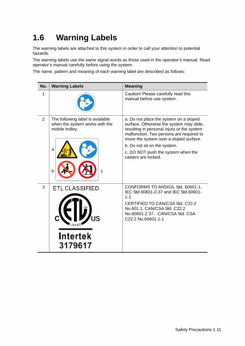
1.6 Warning Labels The warning labels are attached to this system in order to call your attention to potential hazards. The warning labels use the same signal words as those used in the operator’s manual. Read operator’s manual carefully before using the system. The name, pattern and meaning of each warning label are described as follows:
No. Warning Labels Meaning
1
Caution! Please carefully read this manual before use system.
2 The following label is available when the system works with the mobile trolley.
a. Do not place the system on a sloped surface. Otherwise the system may slide, resulting in personal injury or the system malfunction. Two persons are required to move the system over a sloped surface. b. Do not sit on the system. c. DO NOT push the system when the casters are locked.
3
CONFORMS TO ANSI/UL Std. 60601-1, IEC Std 60601-2-37 and IEC Std.60601-1-1 CERTIFIED TO CAN/CSA Std. C22.2 No.601.1, CAN/CSA Std. C22.2 No.60601.2.37,CAN/CSA Std. CSA C22.2 No.60601-1-1
a
b c

System Overview 2-1
2 System Overview
2.1 Intended Use The Diagnostic Ultrasound System is intended for use in abdomen, thoracic, cardiac, tendon, small parts, eyeball and reproductive system for animals such as dog, cat, equine, bovine and ovine etc..
2.2 Contraindication None
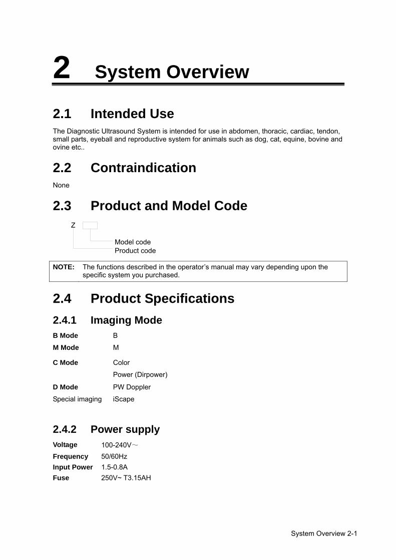
2.3 Product and Model Code
NOTE: The functions described in the operator’s manual may vary depending upon the
specific system you purchased.
2.4 Product Specifications 2.4.1 Imaging Mode B Mode B
M Mode M
C Mode Color
Power (Dirpower)
D Mode PW Doppler
Special imaging iScape
2.4.2 Power supply Voltage 100-240V~ Frequency 50/60Hz Input Power 1.5-0.8A Fuse 250V~ T3.15AH
Z
Model codeProduct code
2-2 System Overview
2.4.3 Environmental Conditions Operational Conditions Storage and Transportation Conditions Ambient temperature
0~40 -20~55
Relative humidity
30%~85% (no condensation) 30%~95% (no condensation)
Atmospheric pressure
700hPa~1060hPa 700hPa~1060hPa
2.4.4 Size and weights Size:
Folded: 190mm×415mm×378mm (Depth×Width×Height) Unfolded: 476mm×415mm×396mm (Depth×Width×Height)
Net Weight:≤8.8kg (including ACDC and battery)
2.5 System Configuration 2.5.1 Standard Configuration
Main unit Accessories
Operator’s manual Power cable Ultrasound gel Multilingual controls overlay Probe holder Dust-proof cover
WARNING: Do not use this system in the conditions other than those specified.
System Overview 2-3
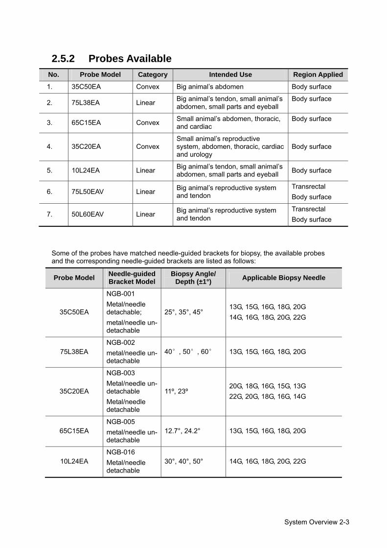
2.5.2 Probes Available No. Probe Model Category Intended Use Region Applied
1. 35C50EA Convex Big animal’s abdomen Body surface
2. 75L38EA Linear Big animal’s tendon, small animal’s abdomen, small parts and eyeball
Body surface
3. 65C15EA Convex Small animal’s abdomen, thoracic, and cardiac
Body surface
4. 35C20EA Convex Small animal’s reproductive system, abdomen, thoracic, cardiac and urology
Body surface
5. 10L24EA Linear Big animal’s tendon, small animal’s abdomen, small parts and eyeball Body surface
6. 75L50EAV Linear Big animal’s reproductive system and tendon
Transrectal Body surface
7. 50L60EAV Linear Big animal’s reproductive system and tendon
Transrectal Body surface
Some of the probes have matched needle-guided brackets for biopsy, the available probes and the corresponding needle-guided brackets are listed as follows:
Probe Model Needle-guided Bracket Model
Biopsy Angle/ Depth (±1°) Applicable Biopsy Needle
35C50EA
NGB-001 Metal/needle detachable; metal/needle un-detachable
25°, 35°, 45° 13G, 15G, 16G, 18G, 20G 14G, 16G, 18G, 20G, 22G
75L38EA NGB-002 metal/needle un-detachable
40°, 50°, 60° 13G, 15G, 16G, 18G, 20G
35C20EA
NGB-003 Metal/needle un-detachable Metal/needle detachable
11º, 23º 20G, 18G, 16G, 15G, 13G 22G, 20G, 18G, 16G, 14G
65C15EA NGB-005 metal/needle un-detachable
12.7°, 24.2° 13G, 15G, 16G, 18G, 20G
10L24EA NGB-016 Metal/needle detachable
30°, 40°, 50° 14G, 16G, 18G, 20G, 22G
2-4 System Overview
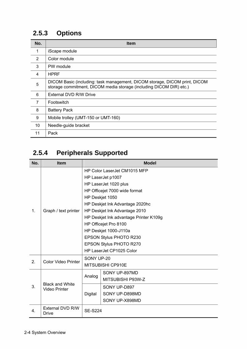
2.5.3 Options No. Item
1 iScape module
2 Color module
3 PW module
4 HPRF
5 DICOM Basic (including: task management, DICOM storage, DICOM print, DICOM storage commitment, DICOM media storage (including DICOM DIR) etc.)
6 External DVD R/W Drive
7 Footswitch
8 Battery Pack
9 Mobile trolley (UMT-150 or UMT-160)
10 Needle-guide bracket
11 Pack
2.5.4 Peripherals Supported No. Item Model
1. Graph / text printer
HP Color LaserJet CM1015 MFP HP LaserJet p1007 HP LaserJet 1020 plus HP Officejet 7000 wide format HP Deskjet 1050 HP Deskjet Ink Advantage 2020hc HP Deskjet Ink Advantage 2010 HP Deskjet Ink advantage Printer K109g HP Officejet Pro 8100 HP Deskjet 1000-J110a EPSON Stylus PHOTO R230 EPSON Stylus PHOTO R270 HP LaserJet CP1025 Color
2. Color Video Printer SONY UP-20 MITSUBISHI CP910E
3. Black and White Video Printer
Analog SONY UP-897MD MITSUBISHI P93W-Z
Digital SONY UP-D897 SONY UP-D898MD SONY UP-X898MD
4. External DVD R/W Drive SE-S224
System Overview 2-5
No. Item Model
5. Footswitch USB port: FS-81-SP-2 (1-pedal) USB port: 971-SWNOM (2-pedal) USB port: 971-SWNOM (3-pedal)
WARNING: This system complies with IEC60601-1-2:2007, and its RF emission meets the requirements of CISPR11 Class B. In a domestic environment, the customer or the user should guarantee to connect the system with Class B peripheral devices; otherwise RF interference may result and the customer or the user must take adequate measures accordingly.
NOTE: If the ultrasound system can not recognize the SONY UP-X898MD and SONY UP-D898MD printers automatically, you may need to change the settings on the printer: push <PUSH ENTER> to enter the main menu and select [DIGITAL]->[DRIVER], and select [897].
2-6 System Overview
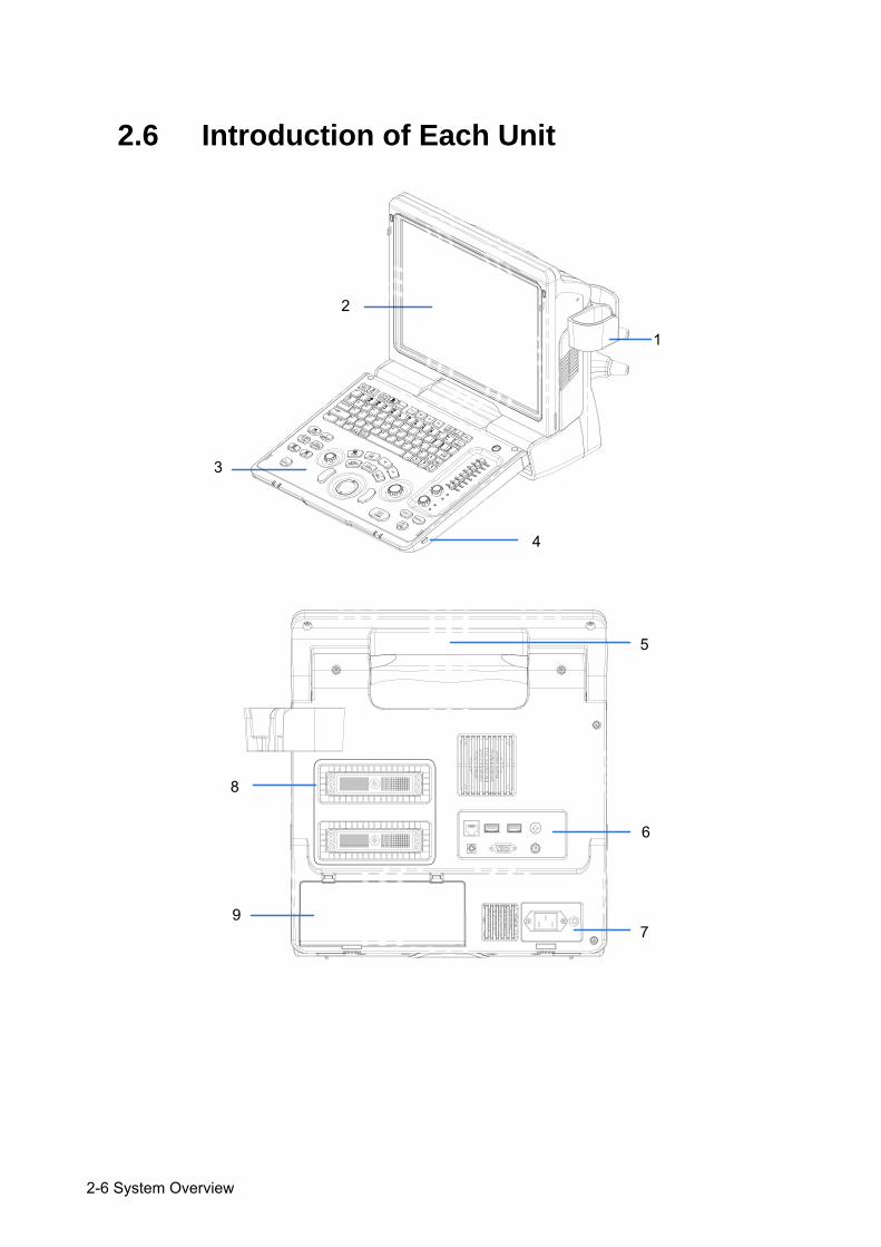
2.6 Introduction of Each Unit
1
2
3
4
5
8
6
7 9
System Overview 2-7
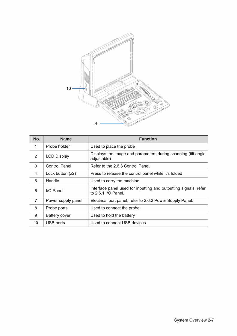
No. Name Function
1 Probe holder Used to place the probe
2 LCD Display Displays the image and parameters during scanning (tilt angle adjustable)
3 Control Panel Refer to the 2.6.3 Control Panel.
4 Lock button (x2) Press to release the control panel while it’s folded
5 Handle Used to carry the machine
6 I/O Panel Interface panel used for inputting and outputting signals, refer to 2.6.1 I/O Panel.
7 Power supply panel Electrical port panel, refer to 2.6.2 Power Supply Panel.
8 Probe ports Used to connect the probe
9 Battery cover Used to hold the battery
10 USB ports Used to connect USB devices
10
4

2-8 System Overview
2.6.1 I/O Panel
<2> <3> <4><1>
<5> <6> <7>VGA
12V
5V
3.3V
A<8>
No. Symbol Function
1 Network port
2 USB ports
3
4 Separate video output, connecting video printer or LCD
5 Remote control port
6 VGA VGA signal output
7 Composite video output
8 / Power indicator
2.6.2 Power Supply Panel
<1>
<2>100-240~ 50/60Hz 1.5-0.8A
No. Name Function
1 Power inlet AC power inlet
2 Equipotential terminal Used for equipotential connection, that balances the protective earth potentials between the system and other electrical equipment.
System Overview 2-9
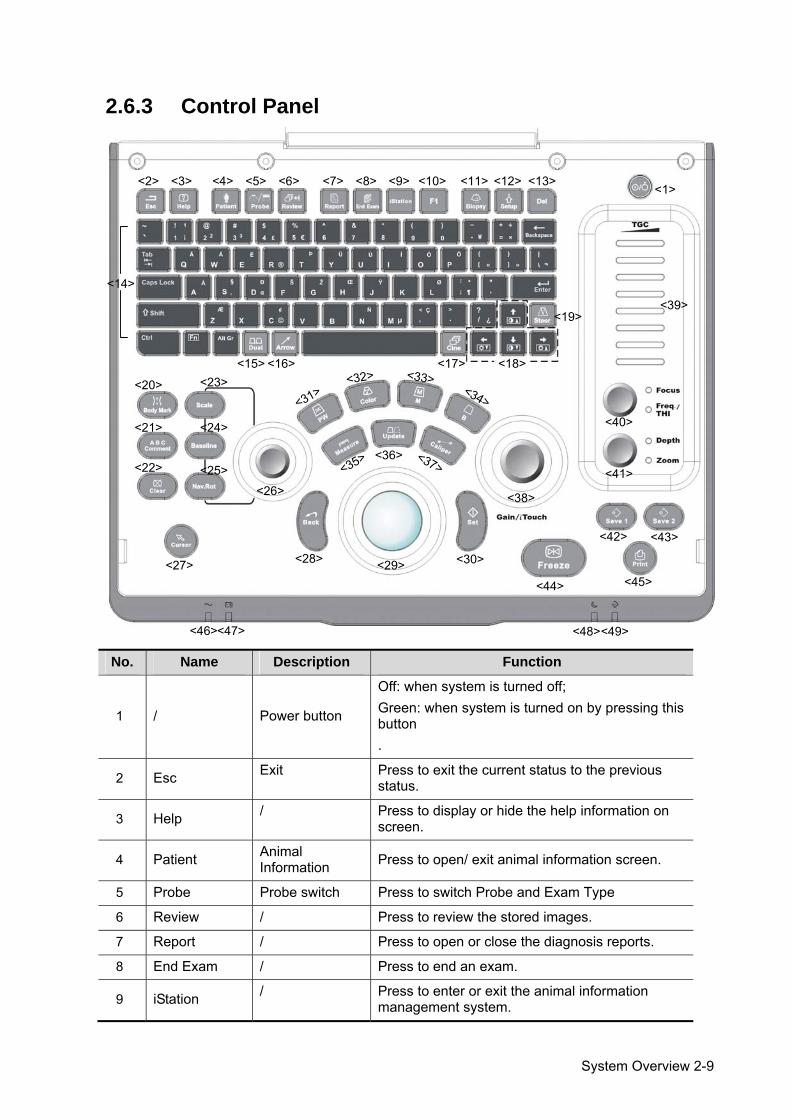
2.6.3 Control Panel
<1><10><9><8><7><6><5><4><3><2> <11> <12> <13>
<14>
<15> <16> <17> <18>
<38>
<39>
<40>
<45><44>
<43><42>
<41><26>
<20>
<19>
<21>
<22>
<23>
<24>
<25> <35>
<32> <33><34>
<37><36>
<31>
<27> <28> <29> <30>
<46><47> <48><49>
No. Name Description Function
1 / Power button
Off: when system is turned off; Green: when system is turned on by pressing this button .
2 Esc Exit Press to exit the current status to the previous status.
3 Help / Press to display or hide the help information on screen.
4 Patient Animal Information Press to open/ exit animal information screen.
5 Probe Probe switch Press to switch Probe and Exam Type
6 Review / Press to review the stored images.
7 Report / Press to open or close the diagnosis reports.
8 End Exam / Press to end an exam.
9 iStation / Press to enter or exit the animal information management system.
2-10 System Overview
No. Name Description Function
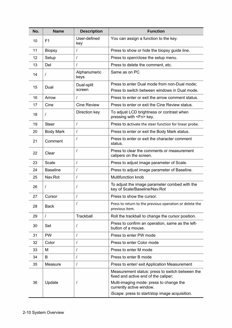
10 F1 User-defined key
You can assign a function to the key.
11 Biopsy / Press to show or hide the biopsy guide line.
12 Setup / Press to open/close the setup menu.
13 Del / Press to delete the comment, etc.
14 / Alphanumeric keys
Same as on PC
15 Dual Dual-split screen
Press to enter Dual mode from non-Dual mode; Press to switch between windows in Dual mode.
16 Arrow / Press to enter or exit the arrow comment status.
17 Cine Cine Review Press to enter or exit the Cine Review status.
18 / Direction key To adjust LCD brightness or contrast when pressing with <Fn> key.
19 Steer / Press to activate the steer function for linear probe.
20 Body Mark / Press to enter or exit the Body Mark status.
21 Comment / Press to enter or exit the character comment status.
22 Clear / Press to clear the comments or measurement calipers on the screen.
23 Scale / Press to adjust image parameter of Scale.
24 Baseline / Press to adjust image parameter of Baseline.
25 Nav.Rot / Multifunction knob
26 / / To adjust the image parameter combed with the key of Scale/Baseline/Nav.Rot
27 Cursor / Press to show the cursor.
28 Back / Press to return to the previous operation or delete the previous item.
29 / Trackball Roll the trackball to change the cursor position.
30 Set / Press to confirm an operation, same as the left-button of a mouse.
31 PW / Press to enter PW mode
32 Color / Press to enter Color mode
33 M / Press to enter M mode
34 B / Press to enter B mode
35 Measure / Press to enter/ exit Application Measurement
36 Update /
Measurement status: press to switch between the fixed and active end of the caliper; Multi-imaging mode: press to change the currently active window. iScape: press to start/stop image acquisition.
System Overview 2-11
No. Name Description Function
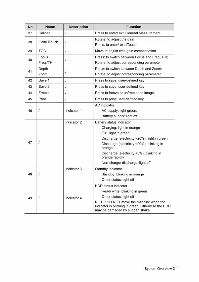
37 Caliper / Press to enter/ exit General Measurement
38 Gain/ iTouch / Rotate: to adjust the gain Press: to enter/ exit iTouch
39 TGC / Move to adjust time gain compensation.
40 Focus Freq./THI
/ Press: to switch between Focus and Freq./THI; Rotate: to adjust corresponding parameter
41 Depth Zoom
/ Press: to switch between Depth and Zoom; Rotate: to adjust corresponding parameter
42 Save 1 / Press to save, user-defined key
43 Save 2 / Press to save, user-defined key
44 Freeze / Press to freeze or unfreeze the image.
45 Print / Press to print: user-defined key.
46 / Indicator 1 AC indicator
AC supply: light green; Battery supply: light off.
47 /
Indicator 2 Battery status indicator Charging: light in orange Full: light in green Discharge (electricity >20%): light in green Discharge (electricity <20%): blinking in orange Discharge (electricity <5%): blinking in orange rapidly Non-charge/ discharge: light off
48 / Indicator 3 Standby indicator
Standby: blinking in orange Other status: light off
49 / Indicator 4
HDD status indicator Read/ write: blinking in green Other status: light off
NOTE: DO NOT move the machine when the indicator is blinking in green. Otherwise the HDD may be damaged by sudden shake.
2-12 System Overview
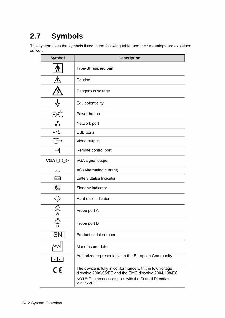
2.7 Symbols This system uses the symbols listed in the following table, and their meanings are explained as well.
Symbol Description
Type-BF applied part
Caution
Dangerous voltage
Equipotentiality
Power button
Network port
USB ports
Video output
Remote control port
VGA VGA signal output
AC (Alternating current)
Battery Status Indicator
Standby indicator
Hard disk indicator
A
Probe port A
B
Probe port B
Product serial number
Manufacture date
Authorized representative in the European Community.
The device is fully in conformance with the low voltage directive 2009/95/EE and the EMC directive 2004/108/EC NOTE: The product complies with the Council Directive 2011/65/EU.
System Preparation 3-1
3 System Preparation
3.1 Move/Posit the System Please read and understand the safety precautions before placing the system to ensure safety for both operator and devices. 1. Switch off the power, and pull out the plug. 2. Disconnect the system from all peripherals. 3. Place the system in a desired location by holding the handle. 4. Leave at least 20cm at the back and both sides of the system.
CAUTION: Maintain enough space around the back and both sides of the system for plugging/ unplugging the power cord, as well as avoiding system failure resulted due to increased system operating temperature.
WARNING: 1. DO NOT connect this system to outlets with the same circuit breakers and fuses that control the current to devices such as life-support systems. If this system malfunctions and generates overcurrent, or when there is an instantaneous current at power ON, the circuit breakers and fuses of the building’s supply circuit may be tripped.
2. Do not connect the three-wire cable of the system with a two-wire receptacle without protective grounding; otherwise electric shock may result.
3. Use the power input cord as the power breaking facility of the system.
3.2 Power Supply This system can work normally only when it is connected to the external power supply or the battery capacity is sufficient.
3.2.1 Connecting External Power Supply A three-wire power cord is used to connect the system with the external power supply. The external power supply system must meet the following requirements:
Voltage: 100-240V~
Frequency: 50/60Hz Input current: 1.5- 0.8 A
3-2 System Preparation
3.2.2 Powered by Battery When connected to the external power supply, the system is powered by the external power. The lithium ion battery inside it is in charging status. When disconnected from the external power supply, the system is powered by the lithium ion batteries.
Refer to “13 Battery” for the detailed operations and precautions.
3.3 Powering ON/ OFF 3.3.1 Powering ON
CAUTION: To ensure safe and effective system operation, you must perform daily maintenance and checks. If the system begins to function improperly – immediately stop scanning. If the system continues to function improperly – fully shut down the system and contact Mindray Customer Service Department or sales representative. If you use the system in a persistent improperly functioning state – you may harm the animal or damage the equipment.
Checking before Power-on
To check the system before turning on the system:
No. Check Item
<1> The temperature, relative humidity and atmospheric pressure shall meet the requirements of operating conditions. See "2.4.3 Environmental Conditions" for details.
<2> There shall be no condensation.
<3>
There shall be no distortion, damage or dirt on the system and peripheral devices. If any dirt is found, cleaning shall be performed as defined in section “16.1.1 Cleaning the System”.
<4> There shall be no loose screws on the LCD or control panel.
<5> There shall be no cable damage (e.g. power cord). Maintaining secure connections to the system at all times.
<6> The probes and probe cables shall be free of damage or stains. See “12.1.5 Probes Cleaning and Disinfection” for details on probe cleaning and disinfection.
<7> No miscellaneous odds and ends are allowed to be attached or affixed to the control panel.
<8> Ensure that all connections are free from damage and remain clear of foreign object blockages. There shall be no obstacles around the system and its air vent.
<9> Probe cleaning and disinfection.
<10> The overall scanning environment and field must be clean.
Checking after it is turned on Press the power button in the upper right corner on the control panel.
System Preparation 3-3
Or press the Power button directly when the battery is of sufficient capacity. To check the system after the system is turned on:
No. Check Item
<1> There shall be no unusual sounds or smells indicating possible overheating.
<2> There shall be no persistently displayed system error message.
<3> There shall be no evident excessive noise, discontinuous, absent or black artifacts in the B Mode image.
<4> Check if there is abnormal heat on the surface of the probe during an ultrasound procedure.
<5> The control panel keys and knobs are fully functional.
<6> The exam date and time are the same as the system date and time, and are displayed correctly.
WARNING: 1. If you use a probe giving off excessive heat, it may burn the animal.
2. If you find anything not functioning properly, this may indicate that the system is defective. In this case, shut down the system immediately and contact Mindray Customer Service Department or sales representative.
NOTE: When you start the system or switch between probes, you will hear clicking sounds – this is expected behavior.
3.3.2 Powering OFF You need to follow the correct procedures to power off the system. In addition, after you upgrade the software or when the system is down, you need to power off and restart it. If you will not use the system for a long period of time, after powering off the system, you shall disconnect the external power supply; turn off powers of all peripherals connected to the system.
To power off your system normally: Gently press the power button once on the upper right corner of the control panel. The [Shutdown Confirm] screen appears. See the figure below.
Shut down: To power off the system normally. Standby: To enter the standby status. Cancel: To cancel the operation.
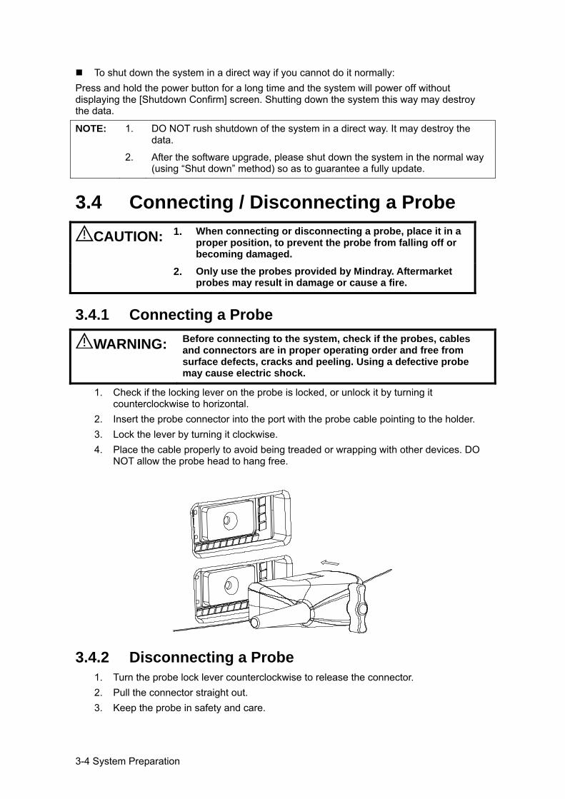
3-4 System Preparation
To shut down the system in a direct way if you cannot do it normally: Press and hold the power button for a long time and the system will power off without displaying the [Shutdown Confirm] screen. Shutting down the system this way may destroy the data.
NOTE: 1. DO NOT rush shutdown of the system in a direct way. It may destroy the data.
2. After the software upgrade, please shut down the system in the normal way (using “Shut down” method) so as to guarantee a fully update.
3.4 Connecting / Disconnecting a Probe CAUTION: 1. When connecting or disconnecting a probe, place it in a
proper position, to prevent the probe from falling off or becoming damaged.
2. Only use the probes provided by Mindray. Aftermarket probes may result in damage or cause a fire.
3.4.1 Connecting a Probe
WARNING: Before connecting to the system, check if the probes, cables and connectors are in proper operating order and free from surface defects, cracks and peeling. Using a defective probe may cause electric shock.
1. Check if the locking lever on the probe is locked, or unlock it by turning it counterclockwise to horizontal.
2. Insert the probe connector into the port with the probe cable pointing to the holder. 3. Lock the lever by turning it clockwise. 4. Place the cable properly to avoid being treaded or wrapping with other devices. DO
NOT allow the probe head to hang free.
3.4.2 Disconnecting a Probe 1. Turn the probe lock lever counterclockwise to release the connector. 2. Pull the connector straight out. 3. Keep the probe in safety and care.
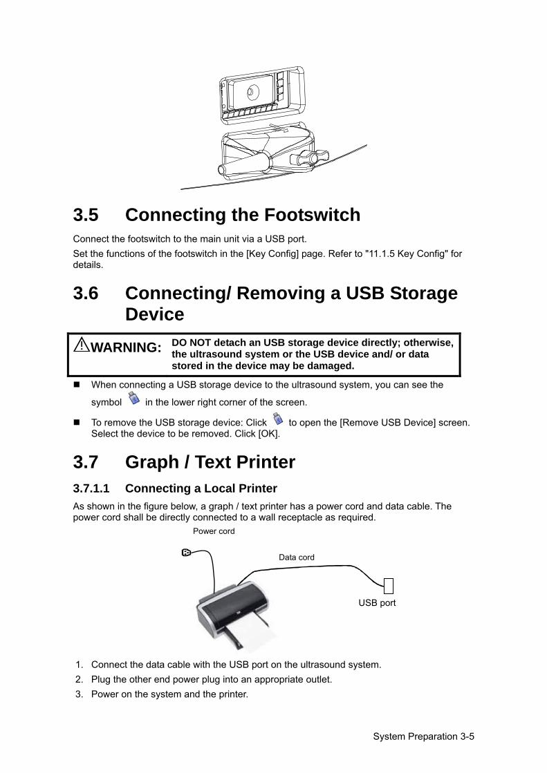
System Preparation 3-5
3.5 Connecting the Footswitch Connect the footswitch to the main unit via a USB port. Set the functions of the footswitch in the [Key Config] page. Refer to "11.1.5 Key Config" for details.
3.6 Connecting/ Removing a USB Storage Device
WARNING: DO NOT detach an USB storage device directly; otherwise, the ultrasound system or the USB device and/ or data stored in the device may be damaged.
When connecting a USB storage device to the ultrasound system, you can see the
symbol in the lower right corner of the screen.
To remove the USB storage device: Click to open the [Remove USB Device] screen. Select the device to be removed. Click [OK].
3.7 Graph / Text Printer 3.7.1.1 Connecting a Local Printer As shown in the figure below, a graph / text printer has a power cord and data cable. The power cord shall be directly connected to a wall receptacle as required.
1. Connect the data cable with the USB port on the ultrasound system. 2. Plug the other end power plug into an appropriate outlet. 3. Power on the system and the printer.
Data cord
USB port
Power cord
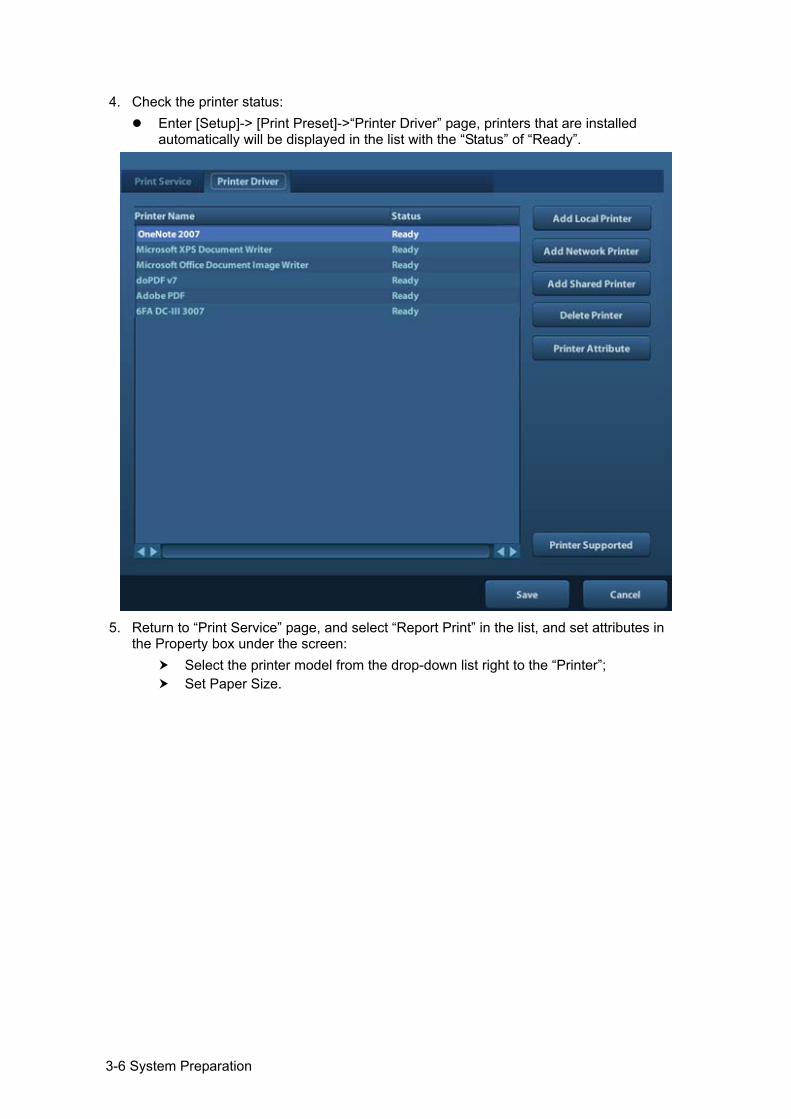
3-6 System Preparation
4. Check the printer status: Enter [Setup]-> [Print Preset]->“Printer Driver” page, printers that are installed
automatically will be displayed in the list with the “Status” of “Ready”.
5. Return to “Print Service” page, and select “Report Print” in the list, and set attributes in
the Property box under the screen: Select the printer model from the drop-down list right to the “Printer”; Set Paper Size.
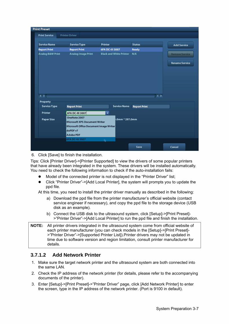
System Preparation 3-7
6. Click [Save] to finish the installation. Tips: Click [Printer Driver]->[Printer Supported] to view the drivers of some popular printers that have already been integrated in the system. These drivers will be installed automatically. You need to check the following information to check if the auto-installation fails:
Model of the connected printer is not displayed in the “Printer Driver” list; Click “Printer Driver”->[Add Local Printer], the system will prompts you to update the
ppd file. At this time, you need to install the printer driver manually as described in the following:
a) Download the ppd file from the printer manufacturer’s official website (contact service engineer if necessary), and copy the ppd file to the storage device (USB disk as an example).
b) Connect the USB disk to the ultrasound system, click [Setup]->[Print Preset]->”Printer Driver”->[Add Local Printer] to run the ppd file and finish the installation.
NOTE: All printer drivers integrated in the ultrasound system come from official website of each printer manufacturer (you can check models in the [Setup]->[Print Preset]->”Printer Driver”->[Supported Printer List]).Printer drivers may not be updated in time due to software version and region limitation, consult printer manufacturer for details.
3.7.1.2 Add Network Printer 1. Make sure the target network printer and the ultrasound system are both connected into
the same LAN. 2. Check the IP address of the network printer (for details, please refer to the accompanying
documents of the printer). 3. Enter [Setup]->[Print Preset]->”Printer Driver” page, click [Add Network Printer] to enter
the screen, type in the IP address of the network printer. (Port is 9100 in default).
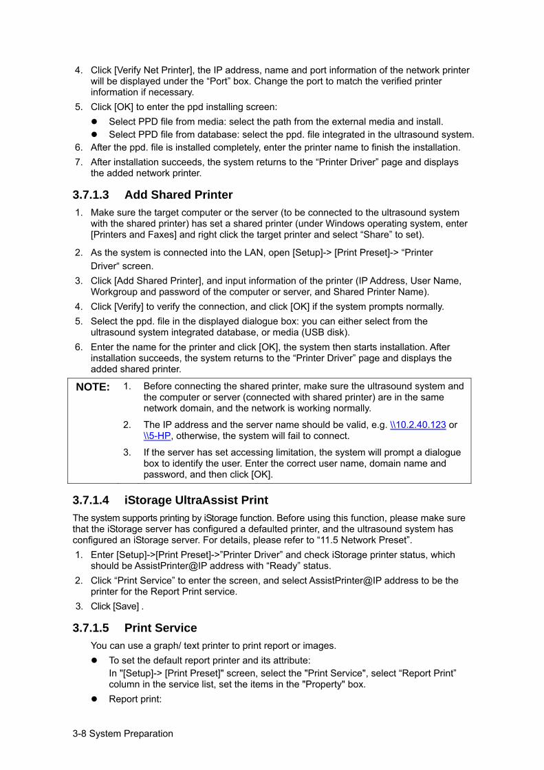
3-8 System Preparation
4. Click [Verify Net Printer], the IP address, name and port information of the network printer will be displayed under the “Port” box. Change the port to match the verified printer information if necessary.
5. Click [OK] to enter the ppd installing screen: Select PPD file from media: select the path from the external media and install. Select PPD file from database: select the ppd. file integrated in the ultrasound system.
6. After the ppd. file is installed completely, enter the printer name to finish the installation. 7. After installation succeeds, the system returns to the “Printer Driver” page and displays
the added network printer.
3.7.1.3 Add Shared Printer 1. Make sure the target computer or the server (to be connected to the ultrasound system
with the shared printer) has set a shared printer (under Windows operating system, enter [Printers and Faxes] and right click the target printer and select “Share” to set).
2. As the system is connected into the LAN, open [Setup]-> [Print Preset]-> “Printer Driver“ screen.
3. Click [Add Shared Printer], and input information of the printer (IP Address, User Name, Workgroup and password of the computer or server, and Shared Printer Name).
4. Click [Verify] to verify the connection, and click [OK] if the system prompts normally. 5. Select the ppd. file in the displayed dialogue box: you can either select from the
ultrasound system integrated database, or media (USB disk). 6. Enter the name for the printer and click [OK], the system then starts installation. After
installation succeeds, the system returns to the “Printer Driver” page and displays the added shared printer.
NOTE: 1. Before connecting the shared printer, make sure the ultrasound system and the computer or server (connected with shared printer) are in the same network domain, and the network is working normally.
2. The IP address and the server name should be valid, e.g. \\10.2.40.123 or \\5-HP, otherwise, the system will fail to connect.
3. If the server has set accessing limitation, the system will prompt a dialogue
box to identify the user. Enter the correct user name, domain name and password, and then click [OK].
3.7.1.4 iStorage UltraAssist Print The system supports printing by iStorage function. Before using this function, please make sure that the iStorage server has configured a defaulted printer, and the ultrasound system has configured an iStorage server. For details, please refer to “11.5 Network Preset”. 1. Enter [Setup]->[Print Preset]->”Printer Driver” and check iStorage printer status, which
should be AssistPrinter@IP address with “Ready” status. 2. Click “Print Service” to enter the screen, and select AssistPrinter@IP address to be the
printer for the Report Print service. 3. Click [Save] .
3.7.1.5 Print Service You can use a graph/ text printer to print report or images.
To set the default report printer and its attribute: In "[Setup]-> [Print Preset]" screen, select the "Print Service", select “Report Print” column in the service list, set the items in the "Property" box.
Report print:
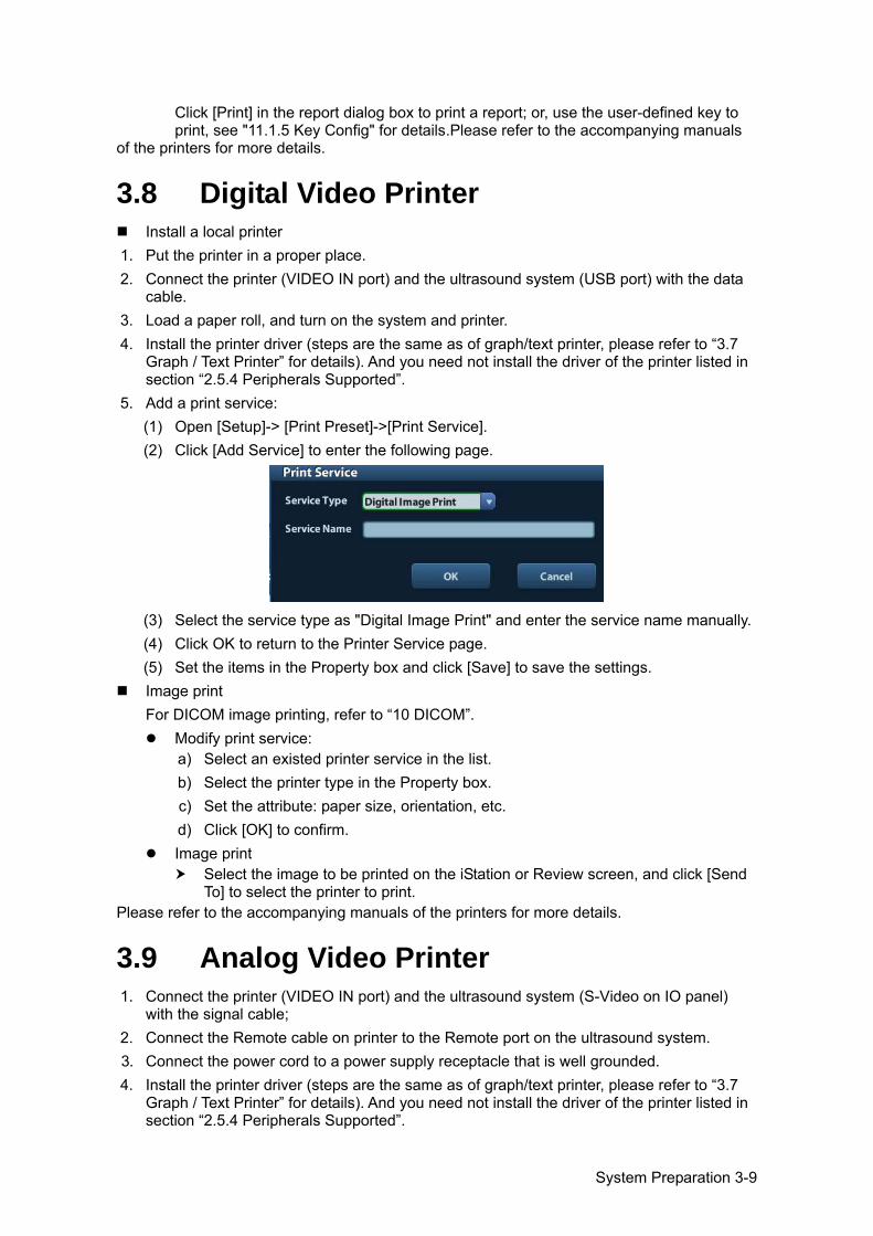
System Preparation 3-9
Click [Print] in the report dialog box to print a report; or, use the user-defined key to print, see "11.1.5 Key Config" for details.Please refer to the accompanying manuals
of the printers for more details.
3.8 Digital Video Printer Install a local printer
1. Put the printer in a proper place. 2. Connect the printer (VIDEO IN port) and the ultrasound system (USB port) with the data
cable. 3. Load a paper roll, and turn on the system and printer. 4. Install the printer driver (steps are the same as of graph/text printer, please refer to “3.7
Graph / Text Printer” for details). And you need not install the driver of the printer listed in section “2.5.4 Peripherals Supported”.
5. Add a print service: (1) Open [Setup]-> [Print Preset]->[Print Service]. (2) Click [Add Service] to enter the following page.
(3) Select the service type as "Digital Image Print" and enter the service name manually. (4) Click OK to return to the Printer Service page. (5) Set the items in the Property box and click [Save] to save the settings.
Image print For DICOM image printing, refer to “10 DICOM”.
Modify print service: a) Select an existed printer service in the list. b) Select the printer type in the Property box. c) Set the attribute: paper size, orientation, etc. d) Click [OK] to confirm.
Image print Select the image to be printed on the iStation or Review screen, and click [Send
To] to select the printer to print. Please refer to the accompanying manuals of the printers for more details.
3.9 Analog Video Printer 1. Connect the printer (VIDEO IN port) and the ultrasound system (S-Video on IO panel)
with the signal cable; 2. Connect the Remote cable on printer to the Remote port on the ultrasound system. 3. Connect the power cord to a power supply receptacle that is well grounded. 4. Install the printer driver (steps are the same as of graph/text printer, please refer to “3.7
Graph / Text Printer” for details). And you need not install the driver of the printer listed in section “2.5.4 Peripherals Supported”.
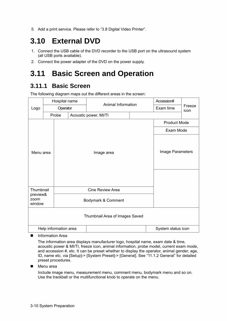
3-10 System Preparation
5. Add a print service. Please refer to “3.8 Digital Video Printer”.
3.10 External DVD 1. Connect the USB cable of the DVD recorder to the USB port on the ultrasound system
(all USB ports available). 2. Connect the power adapter of the DVD on the power supply.
3.11 Basic Screen and Operation 3.11.1 Basic Screen The following diagram maps out the different areas in the screen:
Logo
Hospital name Animal Information
Accession# Freeze icon Operator Exam time
Probe Acoustic power, MI/TI
Menu area Image area
Product Mode
Exam Mode
Image Parameters
Thumbnail preview& zoom window
Cine Review Area
Bodymark & Comment
Thumbnail Area of Images Saved
Help information area System status icon
Information Area The information area displays manufacturer logo, hospital name, exam date & time, acoustic power & MI/TI, freeze icon, animal information, probe model, current exam mode, and accession #, etc. It can be preset whether to display the operator, animal gender, age, ID, name etc. via [Setup]-> [System Preset]-> [General]. See “11.1.2 General” for detailed preset procedures.
Menu area Include image menu, measurement menu, comment menu, bodymark menu and so on. Use the trackball or the multifunctional knob to operate on the menu.
System Preparation 3-11
Image area The image area displays the ultrasound images, probe mark (or activating window mark), time line (in M mode), coordinate axis (including depth, time, velocity/frequency), focus position (located at depth axis in the form of ), besides, the annotation, bodymark, measurement calipers, grayscale bar are also displayed here.
Grayscale/ color bar Displays the grayscale/ color bar corresponding to the current mode.
Cine Review area Displays the cine review progress bar to indicate the cine replay progress.
Thumbnail preview & Zoom Window (image-in-image) In the zoom status, this area displays the thumbnail of a complete image, and a rectangular frame is used to highlight the currently magnified area. This feature is called image-in-image.
Help information area The help information area displays various help information or progress bar in the current status. Besides, the system can provide help for each key. Press [Help] to enter key-help status, you can see the cursor changes into an arrow with a question mark on it. Press any key on the control panel, the screen displays the key-relevant information, meanwhile, the system exits the key-help status. Tips: in terms of help information, “TB” refers to “Trackball”, “Knob refers to Multifunction knob.
Thumbnail area of images stored Displays the thumbnail images stored under the current animal.
System status icon This area displays the relevant system icons, such as USB memory device, printer, network, Chinese / English entry, and current system time, etc.
None-fixing Area Position of areas illustrated here are not fixed, you can move them by the trackball within a certain area on the display.
Result window The measurement result window displays the results of recently performed measurements. To move the result window: a) Place the cursor on the title of result window (you can see the cursor changes
into ). b) Press <Set> and move the trackball, the window moves together with the cursor. c) Move the cursor to the target position, press [Set] again to anchor the result
window in the target position. Comment area
For details, please refer to “8 Comments and Body Marks”. Body mark area
For details, please refer to “8 Comments and Body Marks”.
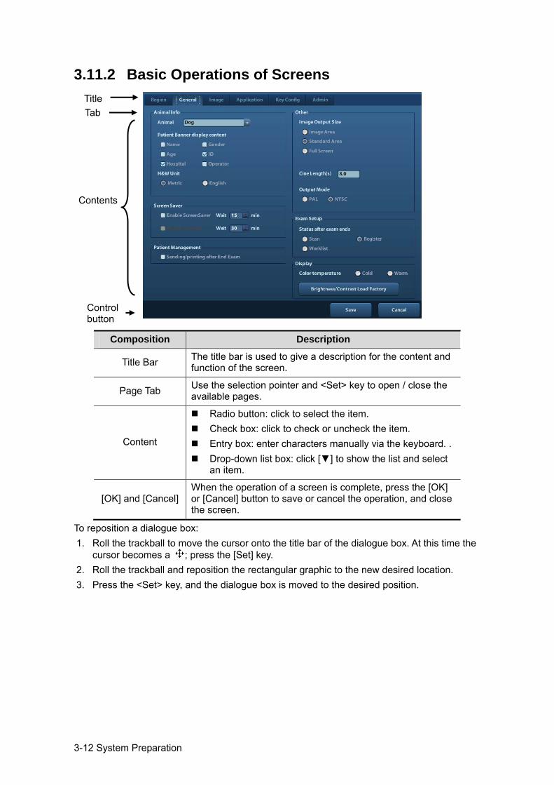
3-12 System Preparation
3.11.2 Basic Operations of Screens
Composition Description
Title Bar The title bar is used to give a description for the content and function of the screen.
Page Tab Use the selection pointer and <Set> key to open / close the available pages.
Content
Radio button: click to select the item. Check box: click to check or uncheck the item. Entry box: enter characters manually via the keyboard. . Drop-down list box: click [] to show the list and select
an item.
[OK] and [Cancel] When the operation of a screen is complete, press the [OK] or [Cancel] button to save or cancel the operation, and close the screen.
To reposition a dialogue box: 1. Roll the trackball to move the cursor onto the title bar of the dialogue box. At this time the
cursor becomes a ; press the [Set] key. 2. Roll the trackball and reposition the rectangular graphic to the new desired location. 3. Press the <Set> key, and the dialogue box is moved to the desired position.
Title Tab
Control button
Contents
Exam Preparation 4-1
4 Exam Preparation
CAUTION: Before examining a new animal, press <End Exam> to end the exam of the previous animal, update the animal ID and information, to avoid mixing data of the next new animal.
4.1 Start an Exam You can start an animal exam in the following situations:
New animal information: to start a new animal exam, enter the animal information first, for details, please refer to “4.2.1 New Animal Information”; however, the system also supports anonymous animal exam, in which you can take the exam without registering animal information.
New exam: to start a new exam for an already recorded animal, the recorded information can be obtained either through iStation or Worklist, refer to "4.2.2.1 iStation" and for details.
Activate an exam: select an exam that is ended within 24 hours, and continue the exam with the imported animal information and exam data. For details, please refer to “4.5 Activate& Continue an Exam”.
Continue an exam: select an exam that is paused within 24 hours, and continue the exam with the imported animal information and exam data. For details, please refer to “4.5 Activate& Continue an Exam”.
General procedure for an exam: enter the animal information-> select an exam mode and probe -> choose an imaging mode -> start the exam. To start a new animal exam, it is better to enter the detailed animal information. The system will set up a unique information database for each animal based on the animal information entered, so that the information of one animal will not be confused with that of another animal.
4.2 Animal Information To enter the "Animal Info" screen
Press <Patient>, or, Move the cursor onto the animal information area on the display and press <Set> to
open the screen. To exit the "Animal Info" screen
Click OK on the "Animal Info" screen; or, press <Patient> on the control panel again, to save the settings and exit the screen.
Click [Cancel] or press <Esc> to exit the screen without saving any of the entered animal data.
Press <B> or <Freeze> to return to the current exam mode with the entered information being saved.
Click [Quick Register] on the screen to save the animal information quickly and return to the main screen.
4.2.1 New Animal Information The Animal Info page is shown as below:
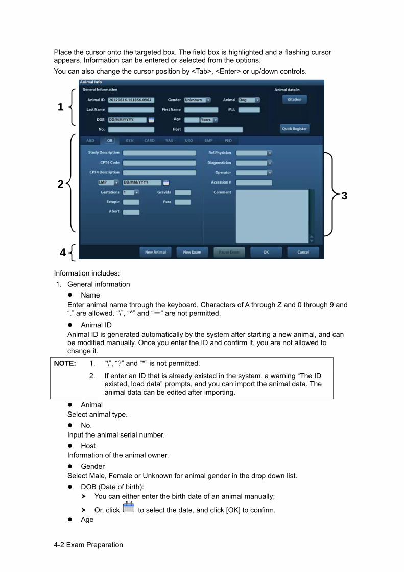
4-2 Exam Preparation
Place the cursor onto the targeted box. The field box is highlighted and a flashing cursor appears. Information can be entered or selected from the options. You can also change the cursor position by <Tab>, <Enter> or up/down controls.
Information includes: 1. General information
Name Enter animal name through the keyboard. Characters of A through Z and 0 through 9 and “.” are allowed. “\”, “^” and “=” are not permitted.
Animal ID Animal ID is generated automatically by the system after starting a new animal, and can be modified manually. Once you enter the ID and confirm it, you are not allowed to change it.
NOTE: 1. “\”, “?” and “*” is not permitted.
2. If enter an ID that is already existed in the system, a warning “The ID existed, load data” prompts, and you can import the animal data. The animal data can be edited after importing.
Animal Select animal type.
No. Input the animal serial number.
Host Information of the animal owner.
Gender Select Male, Female or Unknown for animal gender in the drop down list.
DOB (Date of birth): You can either enter the birth date of an animal manually;
Or, click to select the date, and click [OK] to confirm. Age
3
1
2
4
Exam Preparation 4-3
Auto generated age: once the DOB is gotten, the system can display an auto-generated age in the field box, the unit can be “Years”, “Months” or “Days”. If the age is less than one year, the system will automatically calculate the age in months or days.
Also, you can manually enter the age. NOTE: When you enter the date manually, please enter it in the format as that of the
system.
2. Exam Type Exam application type
You can select among: ABD (Abdomen), OB (Obstetrics), GYN (Gynecology), CARD (Cardiac), VAS (Vascular), URO (Urology), SMP (Small Part), and PED (Pediatrics). Select the exam type tab to enter the exam-specific information.
General information: Study description:
to enter description for each exam.
Primary indications:
to enter the primary indications (reason to perform the exam.)
Secondary indications:
to enter the secondary indications.
CPT4 code: to enter the CPT4 code.
CPT4 description:
to enter the CPT4 description.
Exam specified information:
Exam Type Information Description
ABD (Abdomen)
Height /
Weight /
BSA (body surface area)
After the height and weight are inputted, the system will automatically calculate the BSA based on the formula which is set via [Setup]-> [System Preset]-> [General].
OB (Obstetric)
Date
Select the index type and date. LMP: last menstrual period IVF: in vitro fertilization PRV: previous exam date BBT: basic body temperature EDD: estimated delivery dat
Gravida Times of pregnancy.
Ectopic Times of abnormal pregnancy. e.g. extrauterine pregnancy
Gestations Number of embryos (default value is 1)
Para Times of delivery
Aborta Times of abortion
GYN (Gynecology)
LMP Last menstrual period
Gravida Times of pregnancy.
Para Times of delivery
4-4 Exam Preparation
Exam Type Information Description
Ectopic Times of abnormal pregnancy. e.g. extrauterine pregnancy
Aborta Times of abortion
CARD (Cardiac)
Height /
Weight /
BSA (body surface area)
After the height and weight are inputted, the system will automatically calculate the BSA based on the formula which is set via [Setup] -> [System Preset] ->[General].
BP Blood pressure.
HR /
RA Press Right Atrium Pressure
VAS (Vascular)
BP(L) Input left blood pressure.
BP(R) Input right blood pressure.
URO (Urology)
Serum PSA /
PPSA coefficient /
SMP (Small Parts) None /
PED (Pediatrics) None /
3. Operating Information Ref. Physician: the people who requires the operator to do the ultrasound operation.
“\”, “^” and “=” are not permitted. Diagnostician: people who is responsible for exam. “\”, “^”, “=” and “,” are not
permitted. Operator: people who is responsible for images collection and scanning. “\”, “^” and
“=” are not permitted. Accession #: exam number used in DICOM, “\” is not permitted. Comment: exam-specific explanation or remarks.
4. Functional key [New Patient]: click to clear the current animal information in the animal information
screen in order to input new animal information. [New Exam]: click to clear the current exam information in order to create a new
exam for the current animal. [Pause Exam]: to pause the current exam. [Cancel Exam]: to cancel the current exam. [OK]: click to save the animal data entered and exit the screen. [Cancel]: click to cancel the animal data entered and exit the screen.
4.2.2 Retrieve Animal Information 4.2.2.1 iStation The animal data can be obtained in iStation from the system hardware or USB memory device. You can enter the searching conditions for the animal. 1. To enter iStation screen (the screen is shown as follows):
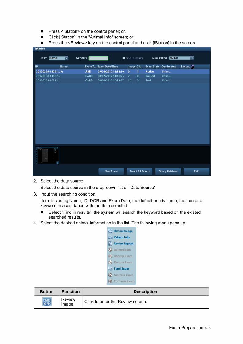
Exam Preparation 4-5
Press <iStation> on the control panel; or, Click [iStation] in the "Animal Info" screen; or Press the <Review> key on the control panel and click [iStation] in the screen.
2. Select the data source:
Select the data source in the drop-down list of "Data Source". 3. Input the searching condition:
Item: including Name, ID, DOB and Exam Date, the default one is name; then enter a keyword in accordance with the Item selected.
Select “Find in results”, the system will search the keyword based on the existed searched results.
4. Select the desired animal information in the list. The following menu pops up:
Button Function Description
Review Image Click to enter the Review screen.
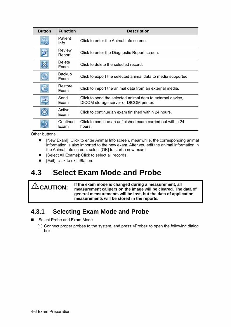
4-6 Exam Preparation
Button Function Description
Patient Info Click to enter the Animal Info screen.
Review Report Click to enter the Diagnostic Report screen.
Delete Exam Click to delete the selected record.
Backup Exam Click to export the selected animal data to media supported.
Restore Exam Click to import the animal data from an external media.
Send Exam
Click to send the selected animal data to external device, DICOM storage server or DICOM printer.
Active Exam Click to continue an exam finished within 24 hours.
Continue Exam
Click to continue an unfinished exam carried out within 24 hours.
Other buttons: [New Exam]: Click to enter Animal Info screen, meanwhile, the corresponding animal
information is also imported to the new exam. After you edit the animal information in the Animal Info screen, select [OK] to start a new exam.
[Select All Exams]: Click to select all records. [Exit]: click to exit iStation.
4.3 Select Exam Mode and Probe
CAUTION: If the exam mode is changed during a measurement, all measurement calipers on the image will be cleared. The data of general measurements will be lost, but the data of application measurements will be stored in the reports.
4.3.1 Selecting Exam Mode and Probe Select Probe and Exam Mode
(1) Connect proper probes to the system, and press <Probe> to open the following dialog box.
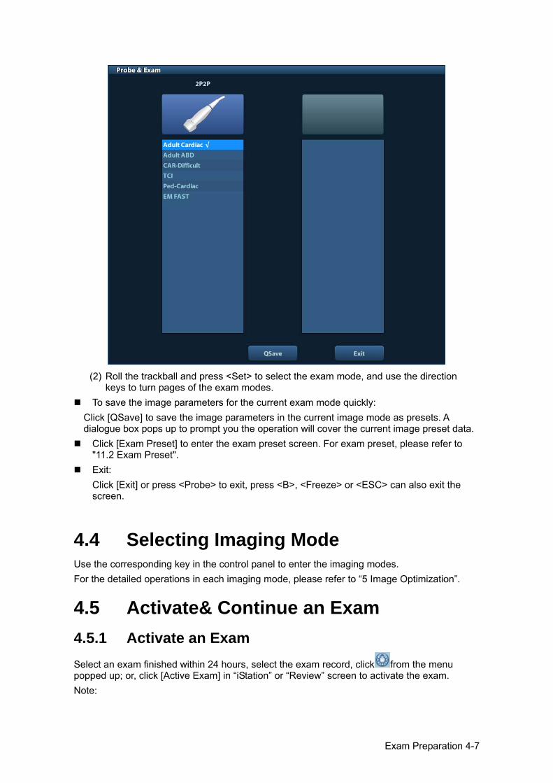
Exam Preparation 4-7
(2) Roll the trackball and press <Set> to select the exam mode, and use the direction
keys to turn pages of the exam modes. To save the image parameters for the current exam mode quickly: Click [QSave] to save the image parameters in the current image mode as presets. A dialogue box pops up to prompt you the operation will cover the current image preset data. Click [Exam Preset] to enter the exam preset screen. For exam preset, please refer to
"11.2 Exam Preset". Exit:
Click [Exit] or press <Probe> to exit, press <B>, <Freeze> or <ESC> can also exit the screen.
4.4 Selecting Imaging Mode Use the corresponding key in the control panel to enter the imaging modes. For the detailed operations in each imaging mode, please refer to “5 Image Optimization”.
4.5 Activate& Continue an Exam 4.5.1 Activate an Exam Select an exam finished within 24 hours, select the exam record, click from the menu popped up; or, click [Active Exam] in “iStation” or “Review” screen to activate the exam. Note:
4-8 Exam Preparation
The system can automatically load the animal information and exam data to continue the exam.
If you want to continue an exam which data lies in an external memory database, you have to first allow the system to load the animal data to the system’s animal database.
4.5.2 Continue an Exam Select an exam paused within 24 hours, select the exam record in iStation screen, click from the menu popped up to continue the exam. If you want to continue an exam which data lies in an external memory database, you have to first allow the system to load the animal data to the system’s animal database.
4.6 Pause & End an Exam 4.6.1 Pause and Exam
Sometimes, you have to stop an uncompleted exam due to some special causes. When the exam is paused, the system can begin other exams.
1. Press <Patient> to enter "Animal Info" screen. 2. Click [Pause Exam]. If the system is powered off during scanning, the exam status turns "paused" after the
system restart. When an exam is paused, the system will: 1. Saves the exam-related images, reports and measurement data, modifies the status as
“Paused”.
2. Save the exam information, including report, imaging mode, exam mode, image parameters, operation mode, imaging / measurement data and so on.
4.6.2 End an Exam Before examining a new animal, press <End Exam> to end the exam of the previous animal, update the animal ID and information, to avoid mixing data of the next new animal. To end an exam, you can do one of the following:
Press <End Exam> on the control panel. Click [New Patient] on the Animal Info screen to end the last animal exam and clear
the animal information. Click [New Exam] on the Animal Info screen (or iStation screen, or Review screen) to
end the last exam and clear the exam data.
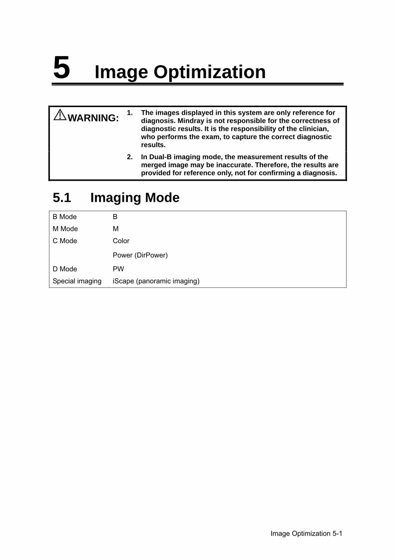
Image Optimization 5-1
5 Image Optimization
WARNING: 1. The images displayed in this system are only reference for diagnosis. Mindray is not responsible for the correctness of diagnostic results. It is the responsibility of the clinician, who performs the exam, to capture the correct diagnostic results.
2. In Dual-B imaging mode, the measurement results of the merged image may be inaccurate. Therefore, the results are provided for reference only, not for confirming a diagnosis.
5.1 Imaging Mode B Mode B
M Mode M
C Mode Color
Power (DirPower)
D Mode PW
Special imaging iScape (panoramic imaging)
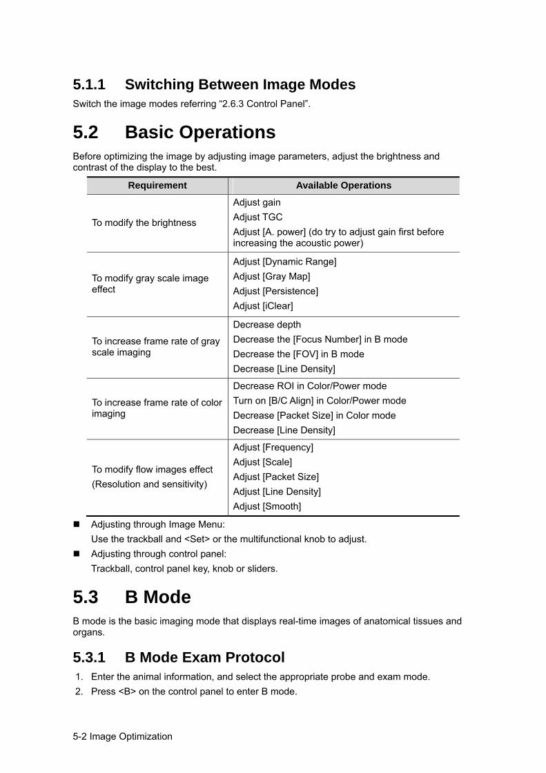
5-2 Image Optimization
5.1.1 Switching Between Image Modes Switch the image modes referring “2.6.3 Control Panel”.
5.2 Basic Operations Before optimizing the image by adjusting image parameters, adjust the brightness and contrast of the display to the best.
Requirement Available Operations
To modify the brightness
Adjust gain Adjust TGC Adjust [A. power] (do try to adjust gain first before increasing the acoustic power)
To modify gray scale image effect
Adjust [Dynamic Range] Adjust [Gray Map] Adjust [Persistence] Adjust [iClear]
To increase frame rate of gray scale imaging
Decrease depth Decrease the [Focus Number] in B mode Decrease the [FOV] in B mode Decrease [Line Density]
To increase frame rate of color imaging
Decrease ROI in Color/Power mode Turn on [B/C Align] in Color/Power mode Decrease [Packet Size] in Color mode Decrease [Line Density]
To modify flow images effect (Resolution and sensitivity)
Adjust [Frequency] Adjust [Scale] Adjust [Packet Size] Adjust [Line Density] Adjust [Smooth]
Adjusting through Image Menu: Use the trackball and <Set> or the multifunctional knob to adjust.
Adjusting through control panel: Trackball, control panel key, knob or sliders.
5.3 B Mode B mode is the basic imaging mode that displays real-time images of anatomical tissues and organs.
5.3.1 B Mode Exam Protocol 1. Enter the animal information, and select the appropriate probe and exam mode. 2. Press <B> on the control panel to enter B mode.
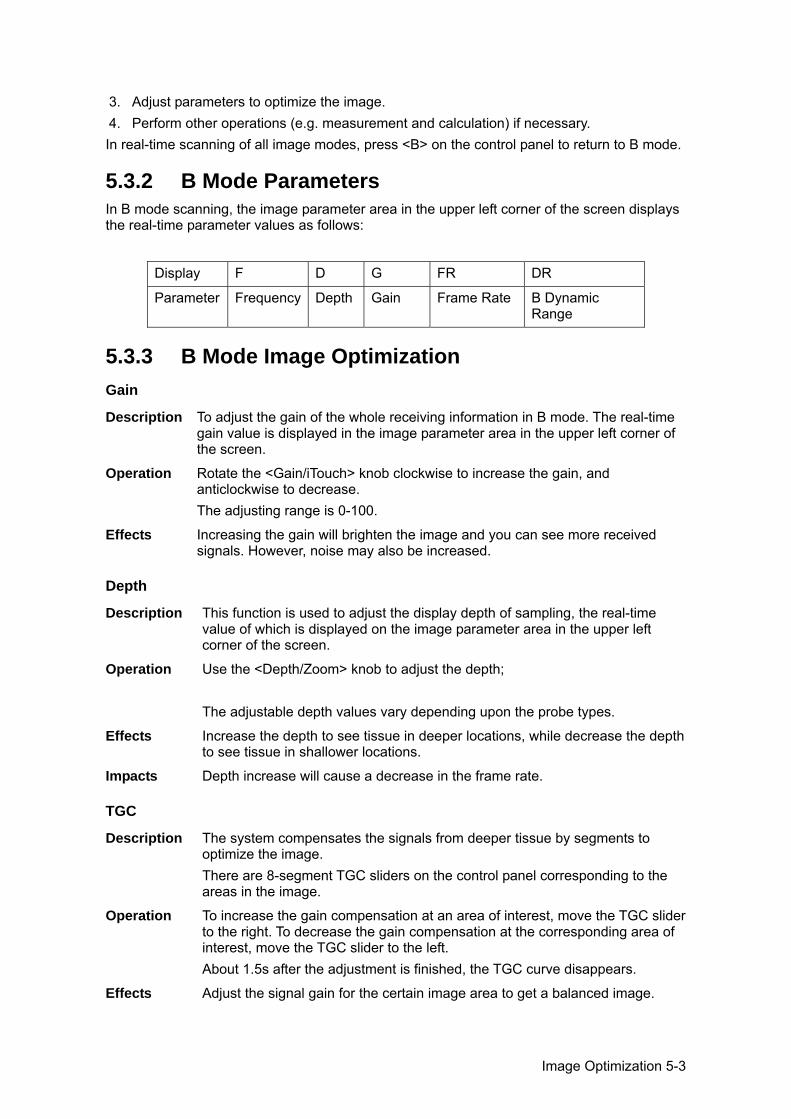
Image Optimization 5-3
3. Adjust parameters to optimize the image. 4. Perform other operations (e.g. measurement and calculation) if necessary. In real-time scanning of all image modes, press <B> on the control panel to return to B mode.
5.3.2 B Mode Parameters In B mode scanning, the image parameter area in the upper left corner of the screen displays the real-time parameter values as follows:
Display F D G FR DR
Parameter Frequency Depth Gain Frame Rate B Dynamic Range
5.3.3 B Mode Image Optimization Gain
Description To adjust the gain of the whole receiving information in B mode. The real-time gain value is displayed in the image parameter area in the upper left corner of the screen.
Operation Rotate the <Gain/iTouch> knob clockwise to increase the gain, and anticlockwise to decrease. The adjusting range is 0-100.
Effects Increasing the gain will brighten the image and you can see more received signals. However, noise may also be increased.
Depth
Description This function is used to adjust the display depth of sampling, the real-time value of which is displayed on the image parameter area in the upper left corner of the screen.
Operation Use the <Depth/Zoom> knob to adjust the depth; The adjustable depth values vary depending upon the probe types.
Effects Increase the depth to see tissue in deeper locations, while decrease the depth to see tissue in shallower locations.
Impacts Depth increase will cause a decrease in the frame rate.
TGC
Description The system compensates the signals from deeper tissue by segments to optimize the image. There are 8-segment TGC sliders on the control panel corresponding to the areas in the image.
Operation To increase the gain compensation at an area of interest, move the TGC slider to the right. To decrease the gain compensation at the corresponding area of interest, move the TGC slider to the left. About 1.5s after the adjustment is finished, the TGC curve disappears.
Effects Adjust the signal gain for the certain image area to get a balanced image.
5-4 Image Optimization
Frequency
Description This function is used to select the operating frequency of the current probe, the real-time value of which is displayed in the image parameter area in the upper left corner of the screen, where “F” represents B mode frequency, and “FH” represents harmonic frequency.
Operation Adjust it through [Frequency] on the image menu or rotate the <Focus/Freq./THI> knob on the control panel, wherein “H” means the harmonic frequency. Values of frequency vary depending upon the probe types. Select the frequency according to the detection depth and current tissue characteristics.
Effects The higher the frequency the better the near field resolution but the worse the force of penetration. Harmonic imaging enhances near field resolution and reduces low-frequency and large amplitude noise, so as to improve small parts imaging.
A. power
Description Refers to the power of ultrasonic wave transmitted by the probe, the real-time value of which is displayed in the image parameter area in the upper left corner of the screen.
Operation Adjust through the [A.Power] item in the image menu; The adjusting range is 7%-100% in increments of 3%.
Effects Generally, increasing the acoustic power will increase the brightness and contrast of the image as well as the force of penetration.
Impacts You should perform exams according to actual situation and follow the ALARA Principle.
Focus
Description Refers to adjustment of focus of the ultrasonic beams, symbols as " " of which will be displayed on the right of the image.
Operation Adjust the focus number through the [Focus Number] in the menu; Adjust the focus position through the [Focus Position] in the menu; In B Mode, focus number can be switched among 1-4.
Effects The area that is focused will be of a higher contrast and resolution to provide a much clearer image.
Impacts The greater the number of focus, the slower the frame rate to image.
Imaging Display Adjustment Description More information can be obtained without moving the probe or changing the
sampling position. FOV (Field of View)
1. To change the scan range, click [FOV] on the image menu to enter the FOV range and FOV position adjustment status.
2. Press <Set> to switch between adjusting FOV position and FOV range. 3. Rotate the trackball to adjust FOV position or the FOV range. When the scan range is adjusted to the widest, the FOV position can not be changed. The FOV position/range is available only for the convex and phased probes.
Image Optimization 5-5
Steer This function is to steer the beam transmitted by the probe.
Adjust it by pressing <Steer> key on the control panel or click [Steer] on the image menu. The steering angles provided are: -6, 0, 6° This function is available only for linear probes..
ExFov Click [ExFov] on the image menu to turn on/off the function. For linear probes, the ExFOv function displays as trapezoid imaging. For convex probes, the ExFOv function displays as extending the scanning angle.
Impacts You can get a much larger field of view when selecting a larger FOV, but the frame rate will decrease.
Line Density
Description The function determines the quality and information of the image.
Operation Adjust through the [Line Density] item in the menu; Levels: UH/ H/ M/ L.
Effects The higher the line density, the higher the resolution, and the lower the frame rate.
Dynamic Range
Description This function is used to adjust the B image resolution to compress or expand the gray display range. The real-time dynamic range value is displayed on the image parameter area in the upper left corner of the screen.
Operation Adjust through the [Dyn Ra.] item in the menu; The adjusting range is 30-220 in increments of 5.
Effects The more the dynamic range, the more specific the information, and the lower the contrast with more noise.
iClear
Description This function is used to increase image profile, so as to distinguish the image boundary.
Operation Adjust through the [iClear] item in the menu; The system provides 5 levels of iClear effects adjustment, off represents no iClear is turned on, and the bigger the value the stronger the effect.
Effects The bigger the value the clearer the profile of the image.
Persistence
Description This function is used to superimpose and average adjacent B images, so as to optimize the image and remove noises.
Operation Adjust through the [Persistence] item in the menu; The system provides 8 level of frame average adjustment, the bigger the value the stronger the effect.
Effects Persistence can remove image noise to make details to be clearer.
5-6 Image Optimization
Impacts Persistence increase may lead to signal missing.
Invert
Description This function provides a better observation for image display.
Invert To invert the image horizontally or vertically. Click [L/R Flip] or [U/D Flip] in the menu to invert the image.
When you flip or rotate an image, the “M” mark will change its position on the screen; the M mark is located in the upper left corner of the imaging area by default.
Impacts The function is available in real-time imaging, freeze or cine review status.
iBeam
Description This function is used to superimpose and average images of different steer angles to obtain image optimization.
Operation Adjust through the [iBeam] item in the menu; Off: no iBeam On: maximum iBeam optimization
Effects Images after iBeam processing can be optimized with less spot noise and higher resolution, so that more details for the structure are revealed.
Impacts iBeam is not available when trapezoid function is turned on.
Auto Merge
Description In the Dual-split mode, when the images of the two windows use the same probe type, depth, invert status, rotation status and magnification factor, the system will merge the two images so as to extend the field of vision.
Operation Turn on/ off the function through the [Auto Merge] item in the menu;
Impacts Available only for linear probes. The function is available in real-time imaging, freeze or cine review status.
Gray Map
Description Adjusting grayscale contras to optimize the image.
Operation Select among the maps through the [Gray Map] item in the menu . The system provides 8 gray maps to be selected among.
Impacts The function is available in real-time imaging, freeze or cine review status.
Tint Map
Description Colorize function provides an imaging process based on color difference rather than gray distinction.
Operation Select the colorize map through the [Tint Map] item in the menu; The system provides 16 colorize maps to be selected among.
Impacts The function is available in real-time imaging, freeze or cine review status.
Image Optimization 5-7
TSI
Description The TSI function is used to optimize the image by selecting acoustic speed according to tissue characteristics.
Operation Select among the TSI modes through the [TSI] item in the menu; The system provided 4 ways of optimization for specific tissues: general, muscle, fluid and fat.
iTouch
Description To optimize image parameters as per the current tissue characteristics for a better image effect.
Operation Press <Gain/ iTouch> on the control panel, the iTouch symbol will display in the image parameter area. Click [iTouch] on the image menu to adjust gain in iTouch status among -12 through 12dB.
Gray Invert
Description Reverse the polarity of the image.
Operation Click [Gray Invert] to turn on or off the image inversion.
Impacts The gray invert functions is available in real-time imaging, freeze or cine review status. Its post process adjustments will not influence the cine review.
HScale
Description Display or hide the width scale (horizontal scale). The scale of the horizontal scale is the same as that of vertical scale (depth), they change together in zoom mode, or when the number of the image window changes. The HScale will be inverted when image is turned up/down.
Operation Click [HScale] on the menu to display or hide the scale.
5.4 M Mode 5.4.1 M Mode Exam Protocol 1. Select a high-quality image during B mode scanning, and adjust to place the area of
interest in the center of the B mode image. 2. Press <M> on the control panel, and roll the trackball to adjust the sampling line. 3. Press <M> on the control panel again or <Update> to enter M mode, then you can
observe the tissue motion along with anatomical images of B mode. 4. During the scanning process, you can also adjust the sampling line accordingly when
necessary. 5. Adjust the image parameters to obtain optimized images. 6. Perform other operations (e.g. measurement and calculation) if necessary.
5-8 Image Optimization
5.4.2 M Mode Parameters In M mode scanning, the image parameter area in the upper left corner of the screen
displays the real-time parameter values as follows:
Display F D DR G V
Parameter Frequency Depth M Dynamic Range M Gain M speed
During M mode imaging, you can switch between B and M menu from the menu title. During M Mode scanning, frequency and acoustic power of the transducer are
synchronous with that of B Mode. Adjustment of the depth or TGC to the B Mode image will lead to corresponding changes
in M Mode image.
5.4.3 M Mode Image Optimization Gain
Description To adjust the gain of M mode image. The real-time gain value is displayed in the image parameter area in the upper left corner of the screen.
Operation Rotate the <Gain/ iTouch> knob clockwise to increase the gain, and anti-clockwise to decrease. The adjusting range is 0-100.
Effects Increasing the gain will brighten the image and you can see more received signals. However, noise may also be increased.
Focus Position
Description To change the focus position in M mode, symbols as " " of which are displayed on the right of the image.
Operation Adjust the focus position through the [Focus Position] item in the menu.
Display Format
Description To set the display format of M mode image with B mode image.
Operation Adjust through the [Display Format] item in the menu; There are 4 formats available for the images display: V2:1, V1:2, V1:1, Full.
Effects Adjust according to the actual situation and obtain a desired analysis through comparison.
Speed
Description This function is used to set the scanning speed of M mode imaging, and the real-time speed value is displayed in the image parameter area in the upper left corner of the screen.
Operation Change the speed through the [Speed] item in the menu; There are 6 levels of scan speed available, the smaller the value the faster the speed.
Image Optimization 5-9
Effects Speed changing makes it easier to identify disorders in cardiac cycles.
Tint Map
Description Colorize function provides an imaging process based on color difference rather than gray distinction.
Operation Select the colorize map through the [Colorize Map] item in the menu; The system provides 16 different maps to be selected among.
Impacts The function is available in real-time imaging, freeze or cine review status.
Gray Map
Description Adjusting grayscale contras to optimize the image.
Operation Select among the maps through the [Gray Map] item in the menu . The system provides 8 gray maps to be selected among.
Impacts The function is available in real-time imaging, freeze or cine review status.
Edge Enhance
Description This function is used to increase image profile, so as to distinguish the image boundary.
Operation Adjust through the [Edge Enhance] item in the menu; The system provides 14 levels of edge enhance effects, off represents no edge enhance is turned on, and the bigger the value the stronger the effect.
Impacts Larger edge enhance may lead to noise increasing.
Dynamic Range
Description Adjusts contrast resolution of an image, compresses or expands gray display range. The real-time dynamic range value is displayed on the image parameter area in the upper left corner of the screen.
Operation Adjust through the [Dyn Ra.] item in the menu; The adjusting range is 30-220 in increments of 5.
Effects The more the dynamic range, the more specific the information, and the lower the contrast with more noise.
M Soften
Description This feature is used to process the scan lines of M images to reject noise, making the image details to be clearer.
Operation Adjust through the [M Soften] item in the menu; The system provides 14 levels of M Soften adjustment, the bigger the value the stronger the effect.
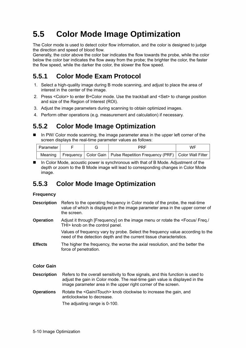
5-10 Image Optimization
5.5 Color Mode Image Optimization The Color mode is used to detect color flow information, and the color is designed to judge the direction and speed of blood flow. Generally, the color above the color bar indicates the flow towards the probe, while the color below the color bar indicates the flow away from the probe; the brighter the color, the faster the flow speed, while the darker the color, the slower the flow speed.
5.5.1 Color Mode Exam Protocol 1. Select a high-quality image during B mode scanning, and adjust to place the area of
interest in the center of the image. 2. Press <Color> to enter B+Color mode. Use the trackball and <Set> to change position
and size of the Region of Interest (ROI). 3. Adjust the image parameters during scanning to obtain optimized images. 4. Perform other operations (e.g. measurement and calculation) if necessary.
5.5.2 Color Mode Image Optimization In PW/ Color mode scanning, the image parameter area in the upper left corner of the
screen displays the real-time parameter values as follows:
Parameter F G PRF WF
Meaning Frequency Color Gain Pulse Repetition Frequency (PRF) Color Wall Filter
In Color Mode, acoustic power is synchronous with that of B Mode. Adjustment of the depth or zoom to the B Mode image will lead to corresponding changes in Color Mode image.
5.5.3 Color Mode Image Optimization Frequency
Description Refers to the operating frequency in Color mode of the probe, the real-time value of which is displayed in the image parameter area in the upper corner of the screen.
Operation Adjust it through [Frequency] on the image menu or rotate the <Focus/ Freq./ THI> knob on the control panel. Values of frequency vary by probe. Select the frequency value according to the need of the detection depth and the current tissue characteristics.
Effects The higher the frequency, the worse the axial resolution, and the better the force of penetration.
Color Gain
Description Refers to the overall sensitivity to flow signals, and this function is used to adjust the gain in Color mode. The real-time gain value is displayed in the image parameter area in the upper right corner of the screen.
Operations Rotate the <Gain/iTouch> knob clockwise to increase the gain, and anticlockwise to decrease. The adjusting range is 0-100.
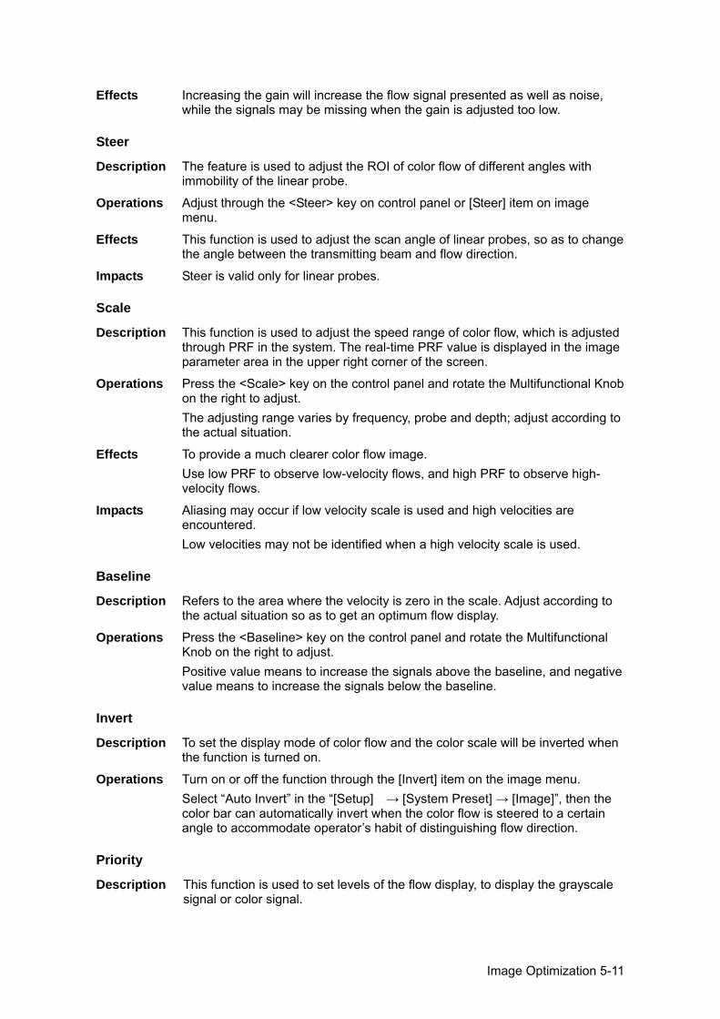
Image Optimization 5-11
Effects Increasing the gain will increase the flow signal presented as well as noise, while the signals may be missing when the gain is adjusted too low.
Steer
Description The feature is used to adjust the ROI of color flow of different angles with immobility of the linear probe.
Operations Adjust through the <Steer> key on control panel or [Steer] item on image menu.
Effects This function is used to adjust the scan angle of linear probes, so as to change the angle between the transmitting beam and flow direction.
Impacts Steer is valid only for linear probes.
Scale
Description This function is used to adjust the speed range of color flow, which is adjusted through PRF in the system. The real-time PRF value is displayed in the image parameter area in the upper right corner of the screen.
Operations Press the <Scale> key on the control panel and rotate the Multifunctional Knob on the right to adjust. The adjusting range varies by frequency, probe and depth; adjust according to the actual situation.
Effects To provide a much clearer color flow image. Use low PRF to observe low-velocity flows, and high PRF to observe high-velocity flows.
Impacts Aliasing may occur if low velocity scale is used and high velocities are encountered. Low velocities may not be identified when a high velocity scale is used.
Baseline
Description Refers to the area where the velocity is zero in the scale. Adjust according to the actual situation so as to get an optimum flow display.
Operations Press the <Baseline> key on the control panel and rotate the Multifunctional Knob on the right to adjust. Positive value means to increase the signals above the baseline, and negative value means to increase the signals below the baseline.
Invert
Description To set the display mode of color flow and the color scale will be inverted when the function is turned on.
Operations Turn on or off the function through the [Invert] item on the image menu. Select “Auto Invert” in the “[Setup] → [System Preset] → [Image]”, then the color bar can automatically invert when the color flow is steered to a certain angle to accommodate operator’s habit of distinguishing flow direction.
Priority
Description This function is used to set levels of the flow display, to display the grayscale signal or color signal.
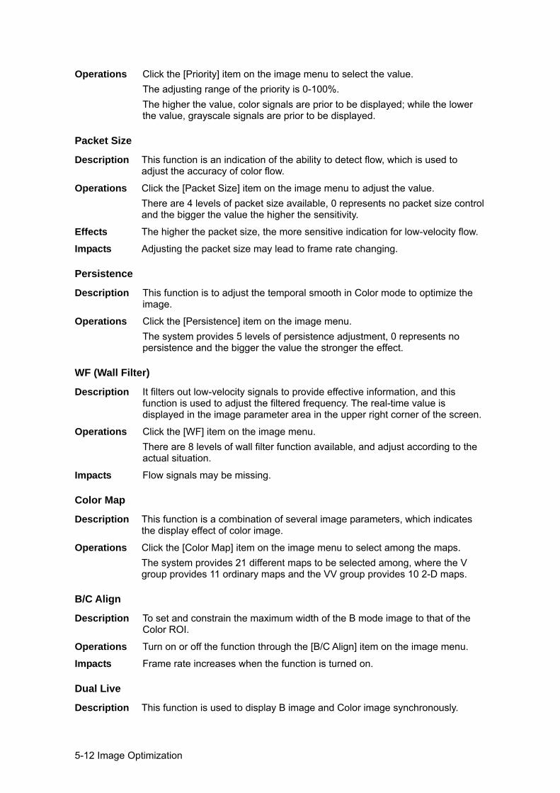
5-12 Image Optimization
Operations Click the [Priority] item on the image menu to select the value. The adjusting range of the priority is 0-100%. The higher the value, color signals are prior to be displayed; while the lower the value, grayscale signals are prior to be displayed.
Packet Size
Description This function is an indication of the ability to detect flow, which is used to adjust the accuracy of color flow.
Operations Click the [Packet Size] item on the image menu to adjust the value. There are 4 levels of packet size available, 0 represents no packet size control and the bigger the value the higher the sensitivity.
Effects The higher the packet size, the more sensitive indication for low-velocity flow.
Impacts Adjusting the packet size may lead to frame rate changing.
Persistence
Description This function is to adjust the temporal smooth in Color mode to optimize the image.
Operations Click the [Persistence] item on the image menu. The system provides 5 levels of persistence adjustment, 0 represents no persistence and the bigger the value the stronger the effect.
WF (Wall Filter)
Description It filters out low-velocity signals to provide effective information, and this function is used to adjust the filtered frequency. The real-time value is displayed in the image parameter area in the upper right corner of the screen.
Operations Click the [WF] item on the image menu. There are 8 levels of wall filter function available, and adjust according to the actual situation.
Impacts Flow signals may be missing.
Color Map
Description This function is a combination of several image parameters, which indicates the display effect of color image.
Operations Click the [Color Map] item on the image menu to select among the maps. The system provides 21 different maps to be selected among, where the V group provides 11 ordinary maps and the VV group provides 10 2-D maps.
B/C Align
Description To set and constrain the maximum width of the B mode image to that of the Color ROI.
Operations Turn on or off the function through the [B/C Align] item on the image menu.
Impacts Frame rate increases when the function is turned on.
Dual Live
Description This function is used to display B image and Color image synchronously.
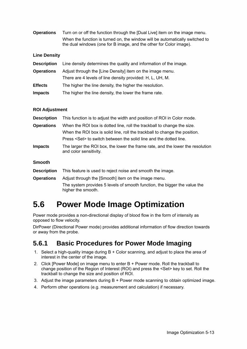
Image Optimization 5-13
Operations Turn on or off the function through the [Dual Live] item on the image menu. When the function is turned on, the window will be automatically switched to the dual windows (one for B image, and the other for Color image).
Line Density
Description Line density determines the quality and information of the image.
Operations Adjust through the [Line Density] item on the image menu. There are 4 levels of line density provided: H, L, UH, M.
Effects The higher the line density, the higher the resolution.
Impacts The higher the line density, the lower the frame rate.
ROI Adjustment
Description This function is to adjust the width and position of ROI in Color mode.
Operations When the ROI box is dotted line, roll the trackball to change the size. When the ROI box is solid line, roll the trackball to change the position. Press <Set> to switch between the solid line and the dotted line.
Impacts The larger the ROI box, the lower the frame rate, and the lower the resolution and color sensitivity.
Smooth
Description This feature is used to reject noise and smooth the image.
Operations Adjust through the [Smooth] item on the image menu. The system provides 5 levels of smooth function, the bigger the value the higher the smooth.
5.6 Power Mode Image Optimization Power mode provides a non-directional display of blood flow in the form of intensity as opposed to flow velocity. DirPower (Directional Power mode) provides additional information of flow direction towards or away from the probe.
5.6.1 Basic Procedures for Power Mode Imaging 1. Select a high-quality image during B + Color scanning, and adjust to place the area of
interest in the center of the image. 2. Click [Power Mode] on image menu to enter B + Power mode. Roll the trackball to
change position of the Region of Interest (ROI) and press the <Set> key to set. Roll the trackball to change the size and position of ROI.
3. Adjust the image parameters during B + Power mode scanning to obtain optimized image. 4. Perform other operations (e.g. measurement and calculation) if necessary.
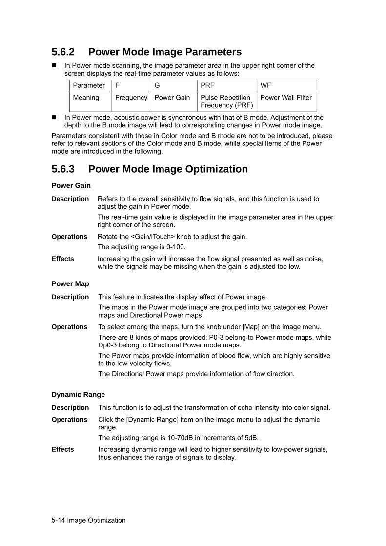
5-14 Image Optimization
5.6.2 Power Mode Image Parameters In Power mode scanning, the image parameter area in the upper right corner of the
screen displays the real-time parameter values as follows:
Parameter F G PRF WF
Meaning Frequency Power Gain Pulse Repetition Frequency (PRF)
Power Wall Filter
In Power mode, acoustic power is synchronous with that of B mode. Adjustment of the depth to the B mode image will lead to corresponding changes in Power mode image.
Parameters consistent with those in Color mode and B mode are not to be introduced, please refer to relevant sections of the Color mode and B mode, while special items of the Power mode are introduced in the following.
5.6.3 Power Mode Image Optimization Power Gain
Description Refers to the overall sensitivity to flow signals, and this function is used to adjust the gain in Power mode. The real-time gain value is displayed in the image parameter area in the upper right corner of the screen.
Operations Rotate the <Gain/iTouch> knob to adjust the gain. The adjusting range is 0-100.
Effects Increasing the gain will increase the flow signal presented as well as noise, while the signals may be missing when the gain is adjusted too low.
Power Map
Description This feature indicates the display effect of Power image. The maps in the Power mode image are grouped into two categories: Power maps and Directional Power maps.
Operations To select among the maps, turn the knob under [Map] on the image menu. There are 8 kinds of maps provided: P0-3 belong to Power mode maps, while Dp0-3 belong to Directional Power mode maps. The Power maps provide information of blood flow, which are highly sensitive to the low-velocity flows. The Directional Power maps provide information of flow direction.
Dynamic Range
Description This function is to adjust the transformation of echo intensity into color signal.
Operations Click the [Dynamic Range] item on the image menu to adjust the dynamic range. The adjusting range is 10-70dB in increments of 5dB.
Effects Increasing dynamic range will lead to higher sensitivity to low-power signals, thus enhances the range of signals to display.
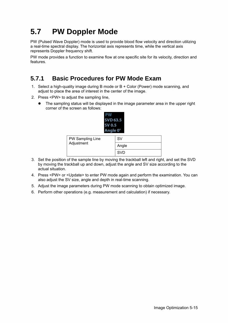
Image Optimization 5-15
5.7 PW Doppler Mode PW (Pulsed Wave Doppler) mode is used to provide blood flow velocity and direction utilizing a real-time spectral display. The horizontal axis represents time, while the vertical axis represents Doppler frequency shift. PW mode provides a function to examine flow at one specific site for its velocity, direction and features.
5.7.1 Basic Procedures for PW Mode Exam 1. Select a high-quality image during B mode or B + Color (Power) mode scanning, and
adjust to place the area of interest in the center of the image. 2. Press <PW> to adjust the sampling line,
The sampling status will be displayed in the image parameter area in the upper right corner of the screen as follows:
PW Sampling Line Adjustment
SV
Angle
SVD
3. Set the position of the sample line by moving the trackball left and right, and set the SVD by moving the trackball up and down, adjust the angle and SV size according to the actual situation.
4. Press <PW> or <Update> to enter PW mode again and perform the examination. You can also adjust the SV size, angle and depth in real-time scanning.
5. Adjust the image parameters during PW mode scanning to obtain optimized image. 6. Perform other operations (e.g. measurement and calculation) if necessary.
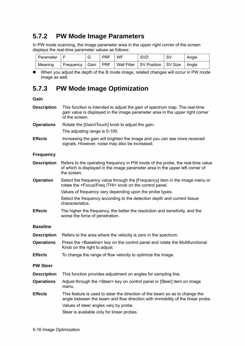
5-16 Image Optimization
5.7.2 PW Mode Image Parameters In PW mode scanning, the image parameter area in the upper right corner of the screen displays the real-time parameter values as follows:
Parameter F G PRF WF SVD SV Angle
Meaning Frequency Gain PRF Wall Filter SV Position SV Size Angle
When you adjust the depth of the B mode image, related changes will occur in PW mode image as well.
5.7.3 PW Mode Image Optimization Gain
Description This function is intended to adjust the gain of spectrum map. The real-time gain value is displayed in the image parameter area in the upper right corner of the screen.
Operations Rotate the [Gain/iTouch] knob to adjust the gain. The adjusting range is 0-100.
Effects Increasing the gain will brighten the image and you can see more received signals. However, noise may also be increased.
Frequency
Description Refers to the operating frequency in PW mode of the probe, the real-time value of which is displayed in the image parameter area in the upper left corner of the screen.
Operation Select the frequency value through the [Frequency] item in the image menu or rotate the <Focus/Freq./THI> knob on the control panel. Values of frequency vary depending upon the probe types. Select the frequency according to the detection depth and current tissue characteristics.
Effects The higher the frequency, the better the resolution and sensitivity, and the worse the force of penetration.
Baseline
Description Refers to the area where the velocity is zero in the spectrum.
Operations Press the <Baseline> key on the control panel and rotate the Multifunctional Knob on the right to adjust.
Effects To change the range of flow velocity to optimize the image.
PW Steer
Description This function provides adjustment on angles for sampling line.
Operations Adjust through the <Steer> key on control panel or [Steer] item on image menu.
Effects This feature is used to steer the direction of the beam so as to change the angle between the beam and flow direction with immobility of the linear probe.Values of steer angles vary by probe. Steer is available only for linear probes.
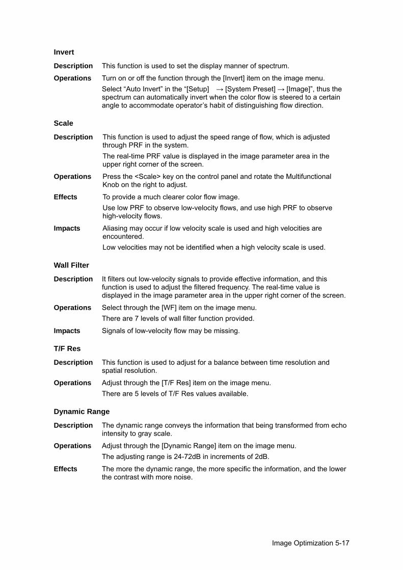
Image Optimization 5-17
Invert
Description This function is used to set the display manner of spectrum.
Operations Turn on or off the function through the [Invert] item on the image menu. Select “Auto Invert” in the “[Setup] → [System Preset] → [Image]”, thus the spectrum can automatically invert when the color flow is steered to a certain angle to accommodate operator’s habit of distinguishing flow direction.
Scale
Description This function is used to adjust the speed range of flow, which is adjusted through PRF in the system. The real-time PRF value is displayed in the image parameter area in the upper right corner of the screen.
Operations Press the <Scale> key on the control panel and rotate the Multifunctional Knob on the right to adjust.
Effects To provide a much clearer color flow image. Use low PRF to observe low-velocity flows, and use high PRF to observe high-velocity flows.
Impacts Aliasing may occur if low velocity scale is used and high velocities are encountered. Low velocities may not be identified when a high velocity scale is used.
Wall Filter
Description It filters out low-velocity signals to provide effective information, and this function is used to adjust the filtered frequency. The real-time value is displayed in the image parameter area in the upper right corner of the screen.
Operations Select through the [WF] item on the image menu. There are 7 levels of wall filter function provided.
Impacts Signals of low-velocity flow may be missing.
T/F Res
Description This function is used to adjust for a balance between time resolution and spatial resolution.
Operations Adjust through the [T/F Res] item on the image menu. There are 5 levels of T/F Res values available.
Dynamic Range
Description The dynamic range conveys the information that being transformed from echo intensity to gray scale.
Operations Adjust through the [Dynamic Range] item on the image menu. The adjusting range is 24-72dB in increments of 2dB.
Effects The more the dynamic range, the more specific the information, and the lower the contrast with more noise.
5-18 Image Optimization
HPRF
Description HPRF mode is used when detected velocities exceed the processing capabilities of the currently selected PW Doppler scale, or when the selected anatomical site is too deep for the selected PW Doppler scale.
Operations Turn on or off the function through the [HPRF] item on the image menu.
Effects HPRF enhances the range of detecting high-velocity flow.
Speed
Description This function is used to set the scanning speed of PW mode imaging.
Operations Click the [Speed] item on the image menu. There are 6 levels of scan speed available, the smaller the value the faster the speed.
Effects Changing the speed makes it easier to identify the cardiac cycles and to detect more details.
Display Format
Description To set the display format of PW mode image with B mode image.
Operations Click the [Display format] item on the image menu to adjust. Options: V2:1, V1:2, V1:1, Full.
Audio
Description This function is used to adjust the output audio in spectrum map.
Operations Click the <Audio> item on the image menu to adjust the volume. The adjusting range of the audio is 0-100%.
Effects Utilizing the output audio helps to identify the feature and status of flow.
Tint Map
Description This function provides an imaging process based on color difference rather than gray distinction.
Operations Click the [Tint Map] item on the image menu to select the map. There are 16 maps available.
Gray Map
Description This function applies the gray correction to obtain the optimum images.
Operations Click the [Gray Map] item on the image menu. There are 8 maps available.
Duplex/ Triplex
Description This function is used to set if B image (B + Color image) and PW image are displayed synchronously.
Operations Click [Duplex/ Triplex] on the image menu to turn on or off the synchronization.
Image Optimization 5-19
Auto Calculation
Description This function is used to trace the spectrum and calculate parameters of PW mode image, and the results of which are displayed in the result window.
Auto Calculation
Turn on or off the auto calculation function through the [Auto Calc] item on the image menu.
Auto Calculation Parameter
Select parameters in the dialogue box prompted by clicking [Auto Calc Param] on the image menu.
Auto Calc Cycle
To set the number of heart cycle for auto calculation. Click [Auto Calc Cycle] on the image menu to select the cycle number.
Operations In real-time scanning, the results displayed are derived from the calculation of latest cardiac cycle; In the freeze and cine status, the results displayed are calculated from the current selected area.
Trace
Trace Area To set the trace area of the Doppler wave in the spectrum map, applicable for auto calculation.
Change the trace area through the [Trace Area] item on the image menu. The available selections are: Above, Below, All.
SV
Description To adjust the SV position and size of sampling in PW mode, the real-time value of SV and SVD are displayed in the image parameter area in the upper right corner of the screen.
SV size Click the [SV] on the image menu to adjust the SV size. Value: 0.5-20mm.
SVD Roll the trackball to select the SV depth.
Effects The smaller the SV size, the more accurate the result; and more details are obtained when selected large SV size.
iTouch
Description To optimize image parameters as per the current tissue characteristics for a better image effect.
Operations Press <Gain/ iTouch> on the control panel to turn on the function.
Angle
Description This function is used to adjust the angle between Doppler vector and flow to make the velocity more accurate. The real-time adjusting angle value is displayed on the right part of the spectrum map.
Operations Click the <Angle> item on the image menu to adjust. The adjustable angle range is -89~89°, in increments of 1°.
5-20 Image Optimization
Quick Angle
Description To adjust the angle faster, in increments 60°, and the real-time value of which is displayed on the right part of the spectrum map.
Operations Click the [Quick Angle] item on the image menu. There are 3 angles for quickly adjustment: -60°, 0°, and 60°.
5.8 iScape The iScape panoramic imaging feature extends your field of view by piecing together multiple B images into a single, extended B image. Use this feature, for example, to view a complete hand or thyroid. When scanning, you move the probe linearly and acquire a series of B images, the system pieces these images together into single, extended B image in real time. Besides, the system supports out-and-back image piecing. After you obtain the extended image, you can rotate it, move it linearly, magnify it, add comments or body marks, or perform measurements on the extended image. You can perform the iScape panoramic imaging feature on B (power) real time images using all linear, convex, and phased probes.
CAUTION: iScape panoramic imaging constructs an extended image from individual image frames. The quality of the resulting image is user-dependent and requires operator skill and additional practice to become fully proficient. Therefore, the measurement results can be inaccurate. Exercise caution when you perform measurements in the iScape mode. Smooth even speed will help produce optimal image results.
Tips: iScape is an optional module, the function is available only if the module has been
installed on the ultrasound system. The display of the biopsy guideline is not allowed in iScape mode.
5.8.1 Basic Procedures for iScape Imaging To perform iScape imaging: 1. Connect an appropriate iScape-compatible probe. Make sure that there is enough
coupling gel along the scan path. 2. Enter iScape:
Click the [iScape] item on the image menu or press the user-defined key of iScape on the control panel. (You can preset a user-defined key via [Setup] -> [System Preset] -> [Key Config].)
3. Optimize the B mode image: In the acquisition preparation status, click the menu title to enter the B mode image optimization. Do measurement or add comment/body mark to the image if necessary.
4. Image acquisition: Click [iScape] menu title to enter the iScape acquisition preparation status. Click [Start Capture] or press <Update> on the control panel to begin the acquisition. For details, please refer to “5.8.2 Image Acquisition”.
Image Optimization 5-21
The system enters into image viewing status when the acquisition is completed. You can perform operations like parameter adjusting. For details, please refer to “5.8.3 iScape Viewing”.
5. Exit iScape: Press <Freeze> or <Update> to return to capturing status.
Press <B> button to return to B mode.Image Acquisition To create an iScape image, you start with an optimized 2D image. The 2D image serves as the mid-line for the resulting iScape image. 1. Press the <Update> key or click [Start Capture] on the image menu to start the iScape
image capture. 2. Scan slowly to obtain a single extended field of view image; you can also perform erasing
and retracing if the image is not satisfied. 3. End image capture:
To end the image capture: Click [Stop Capture] on the image menu; or, Press the <Update> key or <Freeze> key; or, Wait until the acquisition is finished automatically.
After the acquisition is completed, the panoramic image will be displayed. And the system enters iScape viewing mode.
Tips: During the image acquisition, no parameter is adjustable, and functions like
measurement, comment and body mark are not available. ROI: a green box on the image indicating the boundary between the merged images
and the unfinished images. Tips about the probe speed: during image slicing, the system gives feedbacks about
the probe moving speed in the form of color and words, the relations are listed as follows:
Status ROI Color Tips Speed too low Blue Moving speed of the probe is too low.
Appropriate Green None. Speed too high Red Moving speed of the probe is too high.
Guidance and precautions for uniform motion: Make sure that there is enough coupling gel along the scan path. Always move the probe slowly and steadily. Best results are achieved by moving the
probe with 1cm/s - 3cm/s). Continuous contact is required throughout the length of the extended image. Don’t lift
the probe from the skin surface. Always keep the probe perpendicular to the skin surface. Don’t rock, rotate or tilt the
probe during the scan. The system accommodates a reasonable range of motion velocity. Don’t make abrupt
changes in speed of motion. Deeper scans generally require reduced acquisition speed.
5.8.3 iScape Viewing After completing the image acquisition, the system performs image splicing and then enters the iScape viewing mode. In iScape viewing mode, you can perform the following functions:
5-22 Image Optimization
Image parameters setting, for details, please refer to “5.8.3.1 Image Parameters ”. Image zooming, for details, please refer to “5.8.3.2 Image Zooming”. Image rotation, for details, please refer to “5.8.3.3 Rotating the Image”. Measurement, comment, and body mark, for details, please refer to “5.8.3.4
Measurement, Comment, and Body Mark”.
5.8.3.1 Image Parameters Adjusting In image viewing mode, you can adjust the following parameters:
Image size Click [Actual Size] to display the image in its actual size. Click [Fit Size] to display the image in an appropriate size according to the current window. Also this is the system default format.
Tint map Click the [Tint Map] on the menu to adjust it.
Ruler Click [Ruler] on the menu to hide or show the ruler around the image.
5.8.3.2 Image Zooming Press <Depth/Zoom> knob on the control panel to enter image zooming mode. Rotate the knob to zoom in/out the panoramic image.
Rotate clockwise to zoom in the image. Rotate anticlockwise to zoom out the image. Roll the trackball to change position of the magnified image. Press the <Depth/Zoom> knob again to exit the zoom mode. When image displayed is bigger than the image area, the thumbnail is automatically
displayed.
5.8.3.3 Rotating the Image For the convenience of viewing the image, you can rotate the image by clicking [Rotation] on the image menu.
5.8.3.4 Measurement, Comment, and Body Mark In iScape image viewing status, you can perform measurement, comment, and body mark. The operations are the same as that of B mode. NOTE: 1. The measurement accuracy for the spliced image may be degraded, exercise
caution when measurements are performed on an iScape image. 2. If there is a trace during the retracing, please don’t perform measurement
across the trace.
5.8.3.5 Evaluate Image Quality Many variables may affect the overall image quality. It is important to evaluate the image content and quality before an image is used for diagnosis or measurements. NOTE: iScape panoramic imaging is intended for well-trained ultrasound operators or
physicians. The operator must recognize image artifacts that will produce a sub-optimal or unreliable image.
The following artifacts may produce a sub-optimal image. If the image quality cannot meet the following criteria, you shall delete the image and do image acquisition again.
Image Optimization 5-23
The image must be continuous (no part of an image moves suddenly or disappears.) No shadow or absent signal along the scan plane. Clear profile of anatomy through the entire scan plane without distortion. Skin line is continuous. The images are captured from the same plane. There is no large black area in the image.
5.8.4 Cine Review Click [Review Cine] on the image menu in panoramic image viewing status to enter cine reviewing mode. In cine reviewing mode, there is a green frame marker indicating the sequence of currently reviewed image in the panoramic image on the left side of screen. In cine review status:
Roll the trackball to review the captured images frame by frame. Click [Auto Play] to start or end auto play. In auto play mode, click [Auto Play] on the image menu; or, press/rotate the
corresponding knob to change the play speed. When the speed is 0, the system exits auto play mode.
Review to a certain image; click [Set First Frame] to set the start point. Review to another image; click [Set End Frame] to set the end point. In auto play mode, the review region is confined to the set start point and end point.
Click [Return] item on the image menu to exit the cine review mode, and there displays the panoramic image.
In cine review mode, press <Freeze> on the control panel to return to the acquisition preparation status.

Display & Cine Review 6-1
6 Display & Cine Review
6.1 Image Display 6.1.1 Splitting Display The system supports dual-split and quad-split display format. However, only one window is active.
Dual-split: press <Dual> key on the control panel to enter the dual-split mode, and using <Dual> key to switch between the two images; press <B> on the control panel to exit.
Quad-split: press the user-defined Quad key on the control panel to enter the quad-split mode, and using the user-defined key to switch between the two images; press <B> on the control panel to exit.
6.1.2 Image Magnification NOTE: Zooming an image changes the frame rate which tends to change thermal indices.
The position of the focal zones may also change which may cause the peak intensity to occur at a different location in the acoustic filed. As a result, the MI may change.
6.1.2.1 Spot Zoom Procedures: 1. Enter zoom:
In real-time image scanning, press <Depth/Zoom> knob on the control panel to light the Zoom indicator.
2. Adjust ROI: Roll the trackball to change the box size and position, press <Set> to toggle between setting the size and position. And after sample volume is set, press <Zoom> key again to enter spot zoom status.
3. Exit: In spot zooming status, press <Depth/Zoom> again. Note:
Spot zooming only can be realized on a scanning image. The size and position of sample volume box will be changed along with scanning
depth and area.
6.1.2.2 Pan Zoom Procedures: 1. Enter Zoom:
Freeze the image, press <Depth/Zoom> knob on the control panel to light the Zoom indicator. Image-in-image is displayed.
2. Rotate <Depth/Zoom> knob to change the magnification factor among 0.8-10. 3. Exit:
6-2 Display & Cine Review
Press <Depth/Zoom>. Unfreeze the image, the system exit pan zooming status automatically.
6.1.2.3 iZoom (Full-screen Zooming) Function: to magnify the image in full screen.
According to the region to be zoomed, the system supports two types of full-screen zooming:
Zoom in the standard area to full-screen, including image area, parameter area, image banner, thumbnail area and so on.
Zoom in the image area only to full-screen. Procedures:
1. Set the User-defined key: (1) Press <Setup> to enter [Setup] -> [System Preset] -> [Key Config]. (2) Select a function-free key in the function list. (3) Select "iZoom" in the "Other" page. (4) Click [Save] to complete the setting.
2. Open the image(or the under scanning image), press the user-defined iZoom key once to zoom in the standard image area; and then press the key again to zoom in the image area only.
3. Press the user-defined key again to return to normal status. The iZoom status supports:
Measurements, adding comments and body marks. Video output, saving image and printing the current area that is zoomed in. Exiting the zooming status by pressing <Probe>, <Patient>, <iStation>, <Review> or
<Setup>.
6.1.3 Freeze/ Unfreeze the Image Press <Freeze> on the control panel to freeze a scanning image. In freeze mode, the probe stops transmitting acoustic power, and all images as well as the parameters are kept still. Tip: after freezing an image, the system may enter cine review, measure, comment adding, or body mark mode, which is dependent upon preset. (Setting path: [Setup]→[System Preset]→[Image]→"Freeze Config")
Press <Freeze> in freeze mode to unfreeze the image, the system continues image scanning.
6.1.3.1 Imaging Mode Switching When Frozen Imaging mode switching in freeze mode follows the following principles:
In splitting display B mode, press <B> to exit splitting display mode and display the image of the currently activated window in full screen.
In freeze mode, the system supports imaging mode switching between the sub-modes (only for the activated window).
The imaging mode and parameters of an unfrozen image is the same as the corresponding one that before frozen; but the display format is the same as the one before unfrozen.
6.1.3.2 Imaging Display Format Switching When Frozen Image display format switching in freezing mode follows the following principles:
Display & Cine Review 6-3
Dual/quad splitting display mode (Press <Freeze> key in dual/quad splitting display mode) When enters freeze mode, the default activated window is the real-time window
before frozen. Other image windows display the corresponding cine memories, if a certain cine memory is empty, then no image is displayed.
Press <Dual> or <Quad> to switch between dual-splitting and quad-splitting modes. Press <B> button on the control panel to enter the single display format, which
displays the currently activated window. In single display format, press <Dual> or <Quad> to switch between dual-splitting and quad-splitting mode.
Unfrozen: in splitting display status, when you unfreeze the image you can only unfreeze the image in the activated window, other images still keep frozen. In single-window display status, the system displays single image after being unfrozen.
6.2 Cine Review After you press the [Freeze] key, the system allows you to review and edit the images prior to the image frozen. This function is called as cine review. The magnified images can also be reviewed after <Freeze> is pressed, and the operating method is the same. You can perform post process operations, measurements, adding comments and body marks on the images being reviewed. The system supports manual review as well as automatic review. The default mode is Manual Cine, but you can switch between Auto Cine and Manual Cine. In addition, the system supports the images reviewed along with physiological waveforms, if the detection of physiological waveforms is performed.
CAUTION: 1. Cine Review images can be inadvertently combined in-between separate animal scans. The cine memory must be cleared at the end of the current animal and the onset of the next new animal by selecting the <End Exam> key on the control panel.
2. Cine files stored in the system’s hard drive shall contain animal information, to avoid the selection of an incorrect image file and potential misdiagnosis.
6.2.1 Entering/ Exiting Cine Review To enter cine review:
Enter "[Setup]-> [System]-> [Image Preset]-> “Freeze Config”, to set "Status after Freeze" to be "Cine". Then the system enters the manual cine review status once press <Freeze> to freeze the image.
Open cine files in thumbnail, iStation or Review, the system enters automatic cine review status.
To exit cine review: Press <Freeze> key again, the system will return to image scanning and exit cine
review.
6.2.2 Cine Review in 2D Mode 2D mode includes B, B+Color, and B+Power.
Manual Cine Review: After entering the cine review of 2D mode, roll the trackball to review the cine images on the screen one by one.
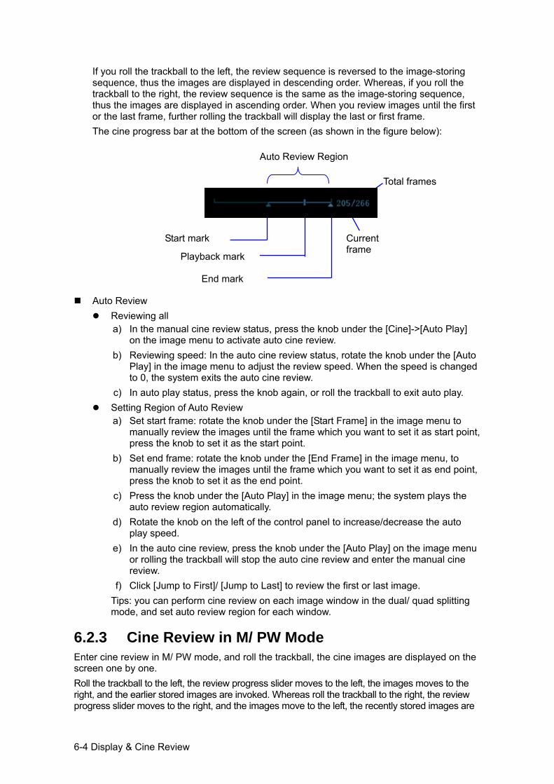
6-4 Display & Cine Review
If you roll the trackball to the left, the review sequence is reversed to the image-storing sequence, thus the images are displayed in descending order. Whereas, if you roll the trackball to the right, the review sequence is the same as the image-storing sequence, thus the images are displayed in ascending order. When you review images until the first or the last frame, further rolling the trackball will display the last or first frame. The cine progress bar at the bottom of the screen (as shown in the figure below):
Auto Review
Reviewing all a) In the manual cine review status, press the knob under the [Cine]->[Auto Play]
on the image menu to activate auto cine review. b) Reviewing speed: In the auto cine review status, rotate the knob under the [Auto
Play] in the image menu to adjust the review speed. When the speed is changed to 0, the system exits the auto cine review.
c) In auto play status, press the knob again, or roll the trackball to exit auto play. Setting Region of Auto Review
a) Set start frame: rotate the knob under the [Start Frame] in the image menu to manually review the images until the frame which you want to set it as start point, press the knob to set it as the start point.
b) Set end frame: rotate the knob under the [End Frame] in the image menu, to manually review the images until the frame which you want to set it as end point, press the knob to set it as the end point.
c) Press the knob under the [Auto Play] in the image menu; the system plays the auto review region automatically.
d) Rotate the knob on the left of the control panel to increase/decrease the auto play speed.
e) In the auto cine review, press the knob under the [Auto Play] on the image menu or rolling the trackball will stop the auto cine review and enter the manual cine review.
f) Click [Jump to First]/ [Jump to Last] to review the first or last image. Tips: you can perform cine review on each image window in the dual/ quad splitting mode, and set auto review region for each window.
6.2.3 Cine Review in M/ PW Mode Enter cine review in M/ PW mode, and roll the trackball, the cine images are displayed on the screen one by one. Roll the trackball to the left, the review progress slider moves to the left, the images moves to the right, and the earlier stored images are invoked. Whereas roll the trackball to the right, the review progress slider moves to the right, and the images move to the left, the recently stored images are
Auto Review Region
Start mark
End mark
Playback mark
Current frame
Total frames
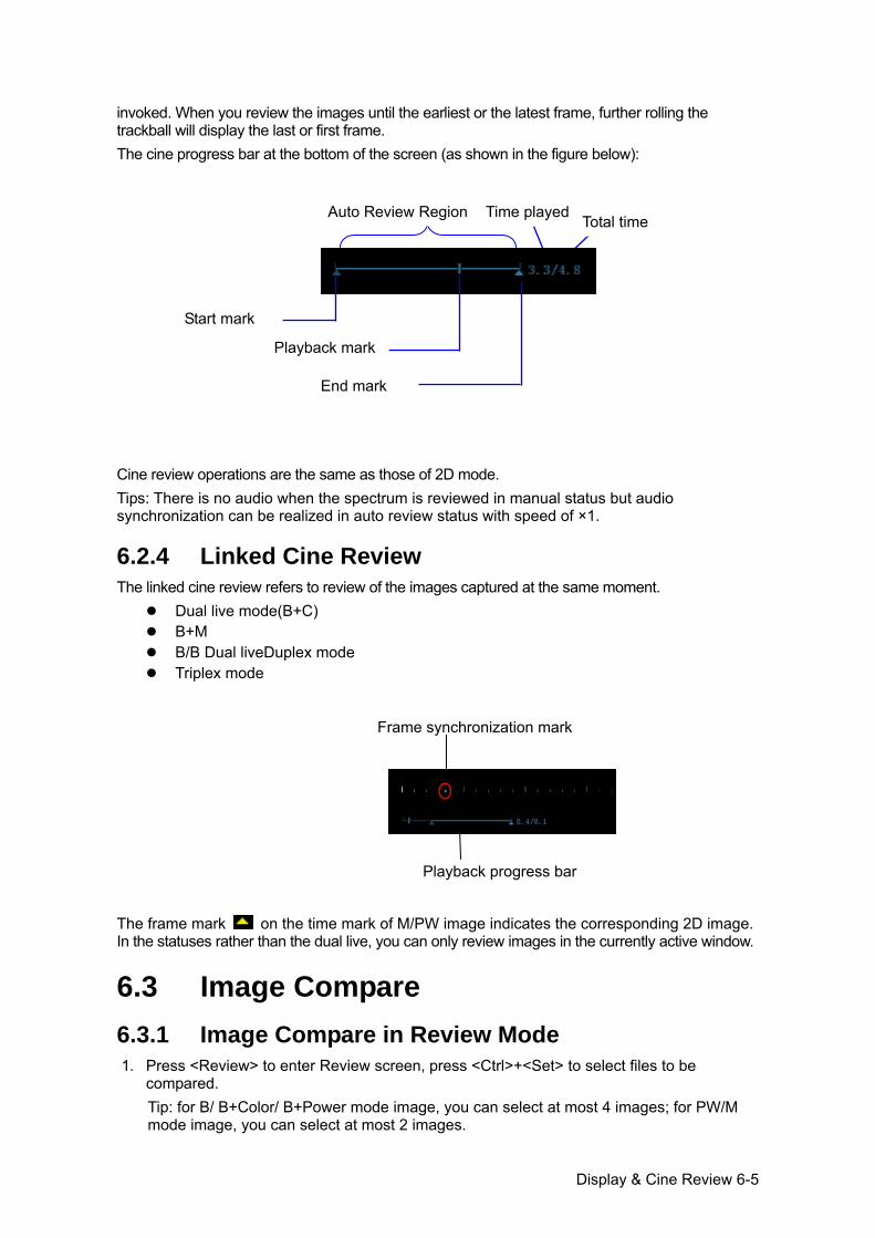
Display & Cine Review 6-5
invoked. When you review the images until the earliest or the latest frame, further rolling the trackball will display the last or first frame. The cine progress bar at the bottom of the screen (as shown in the figure below):
Cine review operations are the same as those of 2D mode. Tips: There is no audio when the spectrum is reviewed in manual status but audio synchronization can be realized in auto review status with speed of ×1.
6.2.4 Linked Cine Review The linked cine review refers to review of the images captured at the same moment.
Dual live mode(B+C) B+M B/B Dual liveDuplex mode Triplex mode
The frame mark on the time mark of M/PW image indicates the corresponding 2D image. In the statuses rather than the dual live, you can only review images in the currently active window.
6.3 Image Compare 6.3.1 Image Compare in Review Mode 1. Press <Review> to enter Review screen, press <Ctrl>+<Set> to select files to be
compared. Tip: for B/ B+Color/ B+Power mode image, you can select at most 4 images; for PW/M mode image, you can select at most 2 images.
Playback progress bar
Frame synchronization mark
Time played Total time
Start mark
End mark
Playback mark
Auto Review Region
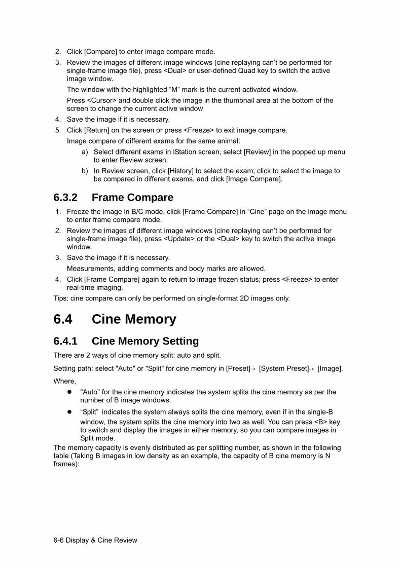
6-6 Display & Cine Review
2. Click [Compare] to enter image compare mode. 3. Review the images of different image windows (cine replaying can’t be performed for
single-frame image file), press <Dual> or user-defined Quad key to switch the active image window. The window with the highlighted “M” mark is the current activated window. Press <Cursor> and double click the image in the thumbnail area at the bottom of the screen to change the current active window
4. Save the image if it is necessary. 5. Click [Return] on the screen or press <Freeze> to exit image compare.
Image compare of different exams for the same animal: a) Select different exams in iStation screen, select [Review] in the popped up menu
to enter Review screen. b) In Review screen, click [History] to select the exam; click to select the image to
be compared in different exams, and click [Image Compare].
6.3.2 Frame Compare 1. Freeze the image in B/C mode, click [Frame Compare] in “Cine” page on the image menu
to enter frame compare mode. 2. Review the images of different image windows (cine replaying can’t be performed for
single-frame image file), press <Update> or the <Dual> key to switch the active image window.
3. Save the image if it is necessary. Measurements, adding comments and body marks are allowed.
4. Click [Frame Compare] again to return to image frozen status; press <Freeze> to enter real-time imaging.
Tips: cine compare can only be performed on single-format 2D images only.
6.4 Cine Memory 6.4.1 Cine Memory Setting There are 2 ways of cine memory split: auto and split.
Setting path: select "Auto" or "Split" for cine memory in [Preset]→ [System Preset]→ [Image].
Where, "Auto" for the cine memory indicates the system splits the cine memory as per the
number of B image windows.
“Split” indicates the system always splits the cine memory, even if in the single-B window, the system splits the cine memory into two as well. You can press <B> key to switch and display the images in either memory, so you can compare images in Split mode.
The memory capacity is evenly distributed as per splitting number, as shown in the following table (Taking B images in low density as an example, the capacity of B cine memory is N frames):
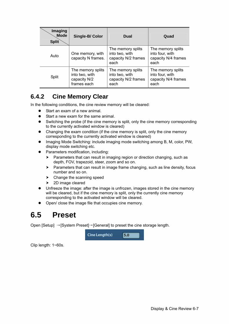
Display & Cine Review 6-7
Imaging Mode
Split Single-B/ Color Dual Quad
Auto One memory, with capacity N frames.
The memory splits into two, with capacity N/2 frames each
The memory splits into four, with capacity N/4 frames each
Split
The memory splits into two, with capacity N/2 frames each
The memory splits into two, with capacity N/2 frames each
The memory splits into four, with capacity N/4 frames each
6.4.2 Cine Memory Clear In the following conditions, the cine review memory will be cleared:
Start an exam of a new animal. Start a new exam for the same animal. Switching the probe (if the cine memory is split, only the cine memory corresponding
to the currently activated window is cleared) Changing the exam condition (if the cine memory is split, only the cine memory
corresponding to the currently activated window is cleared) Imaging Mode Switching: include imaging mode switching among B, M, color, PW,
display mode switching etc. Parameters modification, including:
Parameters that can result in imaging region or direction changing, such as depth, FOV, trapezoid, steer, zoom and so on.
Parameters that can result in image frame changing, such as line density, focus number and so on.
Change the scanning speed 2D image cleared
Unfreeze the image: after the image is unfrozen, images stored in the cine memory will be cleared, but if the cine memory is split, only the currently cine memory corresponding to the activated window will be cleared.
Open/ close the image file that occupies cine memory.
6.5 Preset Open [Setup] →[System Preset]→[General] to preset the cine storage length.
Clip length: 1~60s.

Measurement 7-1
7 Measurement
There are general measurement and application measurement. You can perform measurements on a zoomed image, cine reviewing image, real-time image, or a frozen image. For measurements details, please refer to the [Advanced Volume].
WARNING:Be sure to measure areas of interest from the most optimal image plane to avoid misdiagnosis from inaccurate measurement values.
CAUTION: 1. If an image is unfrozen or the mode is changed during a measurement, the calipers and measurement data will be cleared from the screen. The general measurement data will be lost (the application measurement data are stored in the report).
2. If the system is turned off or <End Exam> is pressed during a measurement, the data not saved will be lost.
3. In Dual-B imaging mode, the measurement results of the merged image may be inaccurate. Therefore, the results are provided for reference only, not for confirming a diagnosis.
7.1 Basic Operations Entering/Exiting Measurement
Enter: on the control panel, press the <Caliper> to enter general measurement; press <Measure> key to enter application measurement. Press <Caliper> or <Measure> key again to exit.
Measurement result and help information The system displays and updates measurement results in the result window. The help information concerning measurement and calculation is displayed in the Help Information area at the bottom of the screen.
7.2 General Measurements 7.2.1 2D General Measurements 2D general measurements refer to general measurements on 2D mode:
Measurement Tools Function
Distance Measures the distance between two points of interest.
Depth The distance between probe surface and the probing point along ultrasound beam.
Angle The angle between two intersected planes.
Area Measures the area and perimeter of a closed region.
7-2 Measurement
Measurement Tools Function
Volume The volume of a target.
Cross Line The length of two line segments, which are perpendicular to each other.
Parallel Line The distance between each pair of parallel lines in a sequence.
Trace Length (Trace) Measures the length of a curve on the image.
Trace Len (Spline) Measures the length of a curve on the image.
Double Dist Measures the length of two line segments, which are perpendicular to each other.
Distance Ratio Measures the lengths of any two line segments and the calculated ratio.
Area Ratio The areas of any two regions and the calculated ratio.
B histogram The grayscale distribution of ultrasonic echo signals in a closed region.
B profile The grayscale distribution of ultrasonic echo signals across a line.
Color Velocity Color flow velocity (only valid for Color mode).
Volume Flow Blood flow through some vascular cross section per unit time.
IMT
Measures the distance between LI (Lumen-Intima) and MA (Media-Adventia) NOTE: The IMT function is unavailable on the product not configured with IMT.
7.2.2 M General Measurements M general measurements refer to general measurements on M mode. The measurements listed below can be performed:
Measurement Tools Function
Distance The vertical distance between two points.
Time The time interval between any two points.
Slope Measures the distance and time between two points and calculates the slope.
HR Measures the time of n (n≤8) cardiac cycles and calculates the heart rate in M mode image.
Velocity Calculates the average velocity by measuring the distance and time between two points.
Measurement 7-3
7.2.3 Doppler General Measurements Doppler general measurements refer to general measurements on PW-mode images. The measurements listed below can be performed:
Measurement Tools Function
Time The time interval between any two points.
HR N intervals (n≤8) are measured to calculate a PW mode derived HR value in Beats Per Minute (BPM).
D Velocity On the Doppler mode image, velocity and PG (pressure gradient) of a point on the Doppler spectrum waveform are measured.
Acceleration Velocity and time interval between two points are measured to calculate speed difference and acceleration.
D Trace On the PW mode image, one or several Doppler waveforms are traced to obtain speed and PG, etc.
PS/ED Velocity and PG between two peaks on the Doppler spectrum to calculate RI (resistance index) and PS/ED (peak systolic/end diastolic).
Volume Flow Blood flow through some vascular cross section per unit time.
7.3 Application Measurement The system support following measurement types:
Abdomen measurements - Used for measurements of abdominal organs (liver, gall bladder, pancreas and kidney, etc.) and large abdominal vessels.
OB measurements- Used for measurements of animal fetus growth indice. Cardiac measurements- Used for left ventricle function measurements and
measurements of main artery and vein parameters, etc. Gynecology measurements - Used for the uterus, ovary and follicles, etc. Small Part measurements – Used for small parts such as thyroid. Urology measurements - Used for urological organs measurements. Vascular measurements – Used for vascular measurements. Pediatric measurements - Used for hip joint measurement. Nerve measurements – Used for nerve structure measurements.
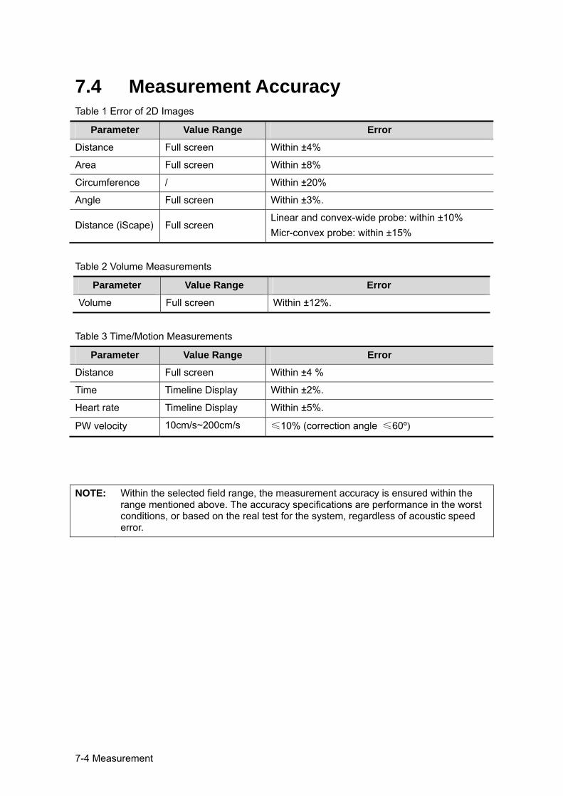
7-4 Measurement
7.4 Measurement Accuracy Table 1 Error of 2D Images
Parameter Value Range Error
Distance Full screen Within ±4%
Area Full screen Within ±8%
Circumference / Within ±20%
Angle Full screen Within ±3%.
Distance (iScape) Full screen Linear and convex-wide probe: within ±10% Micr-convex probe: within ±15%
Table 2 Volume Measurements
Parameter Value Range Error
Volume Full screen Within ±12%.
Table 3 Time/Motion Measurements
Parameter Value Range Error
Distance Full screen Within ±4 %
Time Timeline Display Within ±2%.
Heart rate Timeline Display Within ±5%.
PW velocity 10cm/s~200cm/s ≤10% (correction angle ≤60º)
NOTE: Within the selected field range, the measurement accuracy is ensured within the range mentioned above. The accuracy specifications are performance in the worst conditions, or based on the real test for the system, regardless of acoustic speed error.
Comments and Body Marks 8-1
8 Comments and Body Marks
8.1 Comments Comments can be added to an ultrasound image to bring attention, notate or communicate information observed during the examination. You can add comments to: zoomed image, cine review image, real-time image, frozen image. You can type the character as comments; insert the pre-defined comments from the comment library; or insert arrow markers.
WARNING: You must ensure that the entered comments are correct. Incorrect comments may cause misdiagnosis!
8.1.1 Comment Basic Procedures 1. To enter comment status:
Press the [Comment] key to enter the comment status, and the cursor becomes “|”. Press any alphanumeric key, and the corresponding letter or numeral is displayed
besides the cursor. Press the <Arrow> key to enter the arrow-adding status.
Tips: when the system entered comment status, the default characters entered are uppercase. You can see the <Caps Lock> indicator lights on. 2. Place the cursor to the desired place to set the comment location. Add new comment to
the image according to actual situation. Here, you can modify, move, delete, hide or display the completed comments.
3. To exit comment status: In the comment status, press <Comment> key. Or press <Esc> or other operating mode keys, such as [Caliper], [Measure] etc. In the arrow-adding status, press the <Arrow> key.
8.1.2 Comment Menu You can adjust relevant settings in comment status via menu.
Home of comments Assign the user-defined key for the set home function in “[Setup] → [System Preset] → [Key Config]”. Move the cursor to the desired location for a comment and click the Set-Home user-defined key. The current position of the cursor is set to be the default position of the comment adding. When clicking [Home] user-defined key, the cursor will turn to the default setting position.
Change Font Size/Arrow Size Click [Font Size] to change the font size of comment: Small, Mid, Big. Click [Arrow Size] to change the arrow size of comment: Small, Mid, Big.
The default is the comment text library in the current exam mode. When entered the comment status, the system displays the customized comment text library for the current exam. If there is no customized comment text library for the current exam, it will display the comment text
8-2 Comments and Body Marks
libraries of all the exam modes assigned for the current probe. And if no text library for all the exam modes is customized, no comment text will be displayed.
ABC Display Click [ABC Display] to display or hide the added comments. Assign the user-defined key for the function in “[Setup]-> [System Preset]->“Key Config” ”.
Set comment language Click [English] to turn on or off the English comments. If “English” is turned on, the comments will display in English; if turn off, the comments will display in the language you set. If the current language is English, this selection is not available.
Custom Click [Custom] to display the dialog box containing all comments in current menu, you can edit the comment.
8.1.3 Adding Comments The system can be configured with comment text libraries including Abdomen, Cardiology, GYN(Gynecology), OB(Obstetrics), Urology, SMP(Small Part), Vascular, PED(Pediatric) and Nerve Blocks.
Typing comment characters 1. To set the comment location:
Roll the trackball or press direction-control keys on the keyboard to move the cursor to the desired location for comments.
2. To type the alphanumeric characters: Type the alphanumeric characters through the qwerty (The default characters are
uppercase); To type the upper characters, press [Shift] and the character key at the same time.
3. Move to a new line: In the edit status (the characters are in green color), press <Enter> to move the cursor to the new line, and the location of the cursor is aligned with that of the first line.
4. In the edit status, move the trackball or press the multifunctional knob to confirm the character added, and the color of the character added turns yellow.
Adding a Comment Text Move the cursor onto the desired comment text in the menu and press <Set> or the multifunctional knob, and then the system adds the selected comment text on the set location. The added comment text is in the edit status, so you can edit the comment text added.
Add combined comment: Rotate the knob to view the comments one by one; press the knob again to add the selected item onto the image(comment added in an editable state); rotate the multifunctional knob to search for the next part, and press the knob again to add the second part of the combined comment. Repeat procedures to add other parts of a combined comment. Press <Set> to complete the comment.
Adding an Arrow
You can add an arrow to a location where you want to pay attention. 1. Press the <Arrow> key, and an arrow will appear at the default position. 2. Adjust the arrow
Comments and Body Marks 8-3
Adjust the position and orientation of the arrow: roll the trackball to the desired position and use the multifunctional knob to change the orientation in 15° increments.
Click [Arrow Size] on the menu to change the arrow size: 3. Press <Set> or <Enter> to anchor the arrow position, and then the arrow turns yellow. 4. Repeat the above steps to add more arrows. 5. Press <Arrow> key, <ESC> or to exit the arrow comment status.
8.1.4 Moving Comments 1. Move the cursor onto the comment that needs to be moved. Press <Set> to select it,
where a highlighted box appears around the comment. 2. Roll the trackball to move the comment to the new position. 3. Press the <Set> key to anchor the comment in the new position, and the comment-
moving operation is complete.
8.1.5 Editing Comments Modifying (Editing) characters
1. Move the cursor onto the comment that needs to be modified. Directly enter the character at the position that the cursor stays; or,
Double press the <Set> key to enter the edit status, use the or key to move the cursor to a location where needs to insert characters, and type characters.
2. Press the <Del> key to delete the comment character or text on the right side of the cursor; Press the <Backspace> key to delete the comment character or text on the left side of the cursor.
3. Roll the trackball or press the <Set> key or the multifunctional knob to confirm the modification and to exit the edit status, and the color of the comments turns yellow.
Modifying (Editing) Arrows
1. Move the cursor on the arrow that needs to be modified. After the cursor turns to , press the <Set> key. The color of the current arrow turns green, and there is green frame around the arrow, indicating the arrow can be edited. Move the cursor to change the arrow position.
2. Rotate the multifunctional knob to modify the arrow direction. 3. Press the <Set> or <Enter> key to complete the modifying operation.
8.1.6 Deleting Comments Deleting Comment Characters, Texts or Arrows
1. Move the cursor to the comment to be deleted. 2. Press the <Set> key to select the comment. 3. Press the <Del> or <Clear> key to complete the deleting operation.
Deleting a recently-added character, text or arrow
After you add several comments and the cursor is in the “|” or “ ” status, pressing <Back> can delete the recently-added or recently-edited comment.
Erase All Text Press the <Clear> to delete all the comments.
NOTE: 1. When no object is selected, pressing the <Clear> key will clear all comments and all measurements calipers.
8-4 Comments and Body Marks
2. After powering off, the system will clear all comments on the image.
8.2 Body Mark The Body Mark (Pictogram) feature is used for indicating the exam position of the animal and transducer position and orientation. The system supports body marks for Dog, Cat, Equine, Bovine, Ovine or Other. In addition, the system supports user-defined body marks, and body marks can be imported.
8.2.1 Body Mark Operation Procedures To add the first body mark: 1. Press <Body Mark> to enter the body mark status. 2. Select the body mark, adjust the position and direction of the probe icon. 3. Exit body mark mode:
Press the <Set> key to confirm the position and orientation of the probe marker and exit the body mark mode.
Press [Body Mark] again on the control panel. Press the [Esc] key to confirm the current operation and exit the body mark status.
8.2.2 Menu In the body mark menu. You can:
Select Bodymark library Press the [update] key to select the desired library.
Custom Click [Custom] to load the body mark pictures. You can import a user-defined body mark of PNG and BMP (24/ 32/ 256 bit) image of 75*75 pixels.
8.2.3 Adding Body Marks To add the first body mark:
(1) Enter body mark mode: (2) Select the bodymark library through the menu title. (3) Select the bodymark.
Move the cursor onto the desired bodymark to highlight your choice, and press <Set> to add the selected bodymark; or rotate the multifunctional knob to view the bodymarks.
(4) Press <Set> to confirm the selection. (5) To adjust the probe position and orientation marker:
Roll the trackball to place the probe marker at the correct position. Rotate the multifunctional knob to adjust the orientation. Press the <Set> key to confirm the position and orientation of the probe marker and
exit the body mark mode.
Comments and Body Marks 8-5
8.2.4 Moving Body Marks You can move the body mark graphic to any desired position within the image area.
1. Roll the trackball to move the cursor onto the body mark. The cursor changes into , indicating you can move the pictogram to a new position.
2. Press <Set> key to select the body mark, and a frame will appear around the graphics. 3. Roll the trackball to move the Body Mark graphic to the desired position. 4. Press <Set> to anchor and confirm the new graphics position.
NOTE: In Dual B Mode, a body mark cannot be moved between the separated image windows.
8.2.5 Deleting Body Marks To delete a body mark
1. Use the trackball to position the cursor on the body mark graphic and Press <Set> to select.
2. Press <Clear> to delete the selected body mark.
NOTE: In the Body Mark mode, if no object is selected, pressing the [Clear] key will clear all comments, body marks and general measurements from the screen.
Tips: Powering off, preset returning, switching the exam/ animal/ mode/ probe will clear the
body marks.

Animal Data Management 9-1
9 Animal Data Management
An exam record consists of all information and data of one exam. An exam record consists of the following information:
Animal basic information and exam data Image files Report
NOTE: 1. DO NOT use the internal hard drive for long-term image storage. Daily backup is recommended. External storage media is recommended for image archive.
2. The system animal database space is limited, please back up or clear animal data in time.
3. Mindray is not responsible for lost data if you DO NOT follow suggested backup procedures.
9.1 Animal Information Management 9.1.1 Enter Animal Information The general animal information and exam information are entered through the Animal Info screen, for details, please refer to “4.2 Animal ”. After completion of animal information entry, click [OK] to save the animal information to the animal data.
9.2 Image File Management You can store the image files either in the animal database in the system, or to external memory devices. For a save image, you can perform operations like image reviewing, analyzing and demonstration (iVision).
9.2.1 Storage Media System supported memory media including:
System hard disk USB memory devices: USB flash drive, removable USB hard disk DVD±RW, CD-R/W
9.2.2 Image File Formats The system supports two types of image file formats: system-relevant and PC-compatible.
System-relevant formats: Single-frame image file (FRM)
Refers to single-frame static image files not to be compressed; you can perform measurements and comments adding on this type of files.
Cine file (CIN)
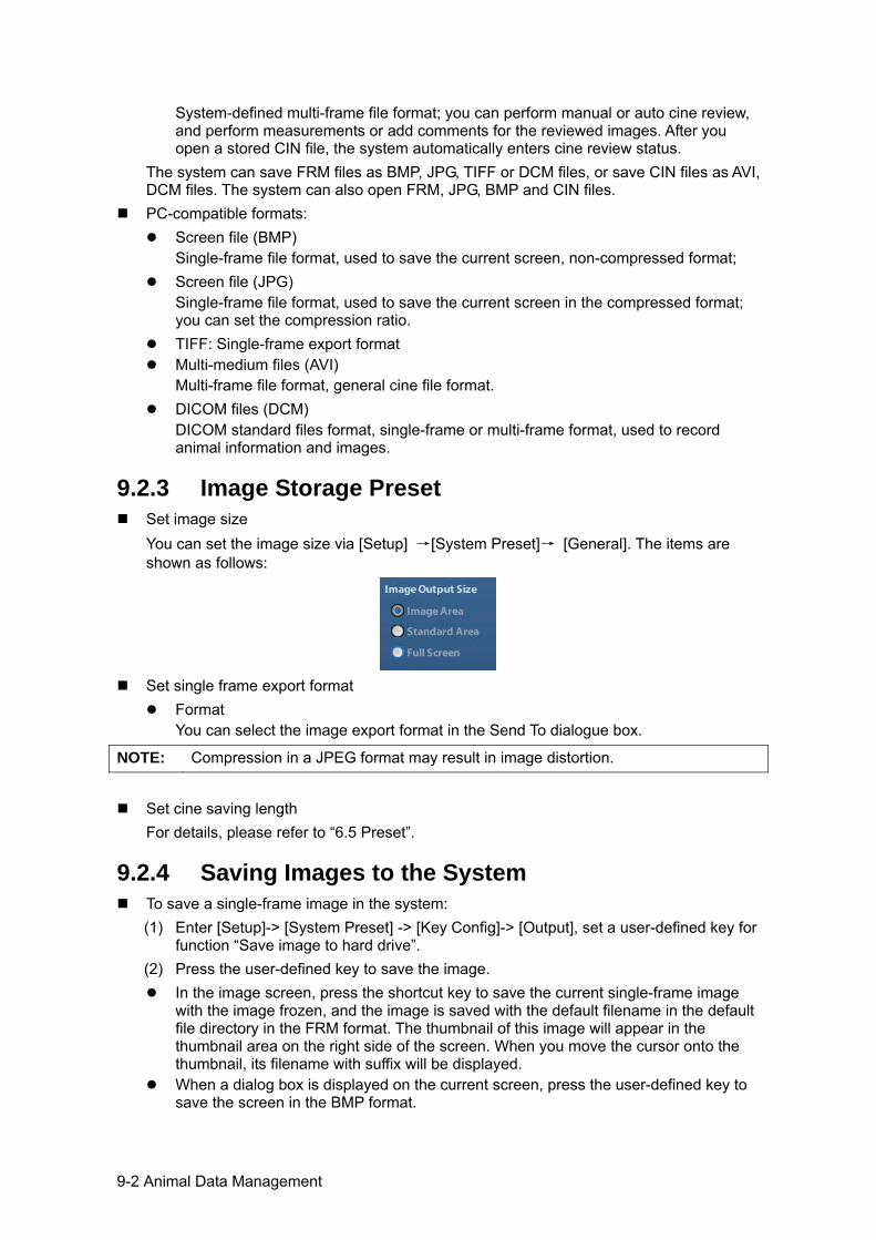
9-2 Animal Data Management
System-defined multi-frame file format; you can perform manual or auto cine review, and perform measurements or add comments for the reviewed images. After you open a stored CIN file, the system automatically enters cine review status.
The system can save FRM files as BMP, JPG, TIFF or DCM files, or save CIN files as AVI, DCM files. The system can also open FRM, JPG, BMP and CIN files.
PC-compatible formats: Screen file (BMP)
Single-frame file format, used to save the current screen, non-compressed format; Screen file (JPG)
Single-frame file format, used to save the current screen in the compressed format; you can set the compression ratio.
TIFF: Single-frame export format Multi-medium files (AVI)
Multi-frame file format, general cine file format. DICOM files (DCM)
DICOM standard files format, single-frame or multi-frame format, used to record animal information and images.
9.2.3 Image Storage Preset Set image size
You can set the image size via [Setup] →[System Preset]→ [General]. The items are shown as follows:
Set single frame export format
Format You can select the image export format in the Send To dialogue box.
NOTE: Compression in a JPEG format may result in image distortion.
Set cine saving length
For details, please refer to “6.5 Preset”.
9.2.4 Saving Images to the System To save a single-frame image in the system:
(1) Enter [Setup]-> [System Preset] -> [Key Config]-> [Output], set a user-defined key for function “Save image to hard drive”.
(2) Press the user-defined key to save the image. In the image screen, press the shortcut key to save the current single-frame image
with the image frozen, and the image is saved with the default filename in the default file directory in the FRM format. The thumbnail of this image will appear in the thumbnail area on the right side of the screen. When you move the cursor onto the thumbnail, its filename with suffix will be displayed.
When a dialog box is displayed on the current screen, press the user-defined key to save the screen in the BMP format.
Animal Data Management 9-3
To save cineloop image in the system: (1) Enter [Setup]-> [System Preset] -> [Key Config]-> [Output], set a user-defined key for
function “Save cine”. (2) Freeze an image. Click the user-defined key to save the current image file in the
default file directory in the dynamic image format .CIN. The thumbnail of this image will appear in the thumbnail area on the lower side of the screen. When you move the cursor onto the thumbnail, its filename with suffix will be displayed.
9.2.5 Quickly Saving Images to USB Flash Drive Use user-defined keys to quickly save the single-frame or cine to USB flash drive. The image file is stored in the directory: U disk\ US Export\ animal folder\ exam folder\ Image ID.bmp, here,
Animal folder name: animal name+ animal ID Exam folder name: exam mode+ exam time
To store single-frame image to USB flash drive: (1) Set the user-defined key through the path: [Setup]→ [System Preset]→ [Key Config].
Select a key in the Key Function page on the left side and select “Send image to USB disk” in the Output page of Function field on the right side.
(2) Save the Preset and return to the main screen. (3) Press the user-defined key to save the image to the USB flash drive.
To store cine to USB flash drive Save cine images to a USB flash drive in the AVI format. (1) Set the user-defined key through the path: [Setup]→ [System Preset]→ [Key Config].
Select a key in the Key Function page on the left side and select “Send AVI Cine to USB disk” in the Output page of Function field on the right side.
(2) Save the Preset and return to the main screen, scan and freeze an image. (3) Press the user-defined key to save the cineloop.
9.2.6 Quickly Saving Full Screen Image to the System This function can save the current full screen image to the system with the image in real-time status. 1. Set the user-defined key through the path: [Setup](by pressing <Setup>)→ [System
Preset]→ [Key Config]. Select a key in the Key Function page on the left side and select “Send Full Screen Image to hard drive” in the Output page of Function field on the right side.
2. After the setting, you can use the user-defined key to save full screen image to the system.
9.2.7 Thumbnails The stored images or cineloops are displayed in the form of thumbnails on the screen:
In the iStation screen, the thumbnails refer to the images stored for the selected exam or the selected animal.
In the scanning or freeze mode, the thumbnails refer to the images stored in the current exam.
In the Review screen, the thumbnails refer to the images stored in the same exam. In the Review screen, open an image to enter the image analyzing status, all the
thumbnails belong to the exam are displayed.
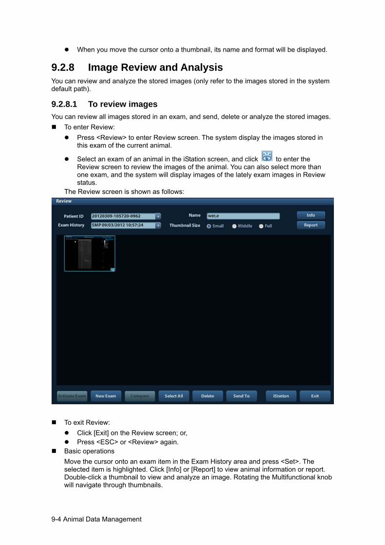
9-4 Animal Data Management
When you move the cursor onto a thumbnail, its name and format will be displayed.
9.2.8 Image Review and Analysis You can review and analyze the stored images (only refer to the images stored in the system default path).
9.2.8.1 To review images You can review all images stored in an exam, and send, delete or analyze the stored images.
To enter Review: Press <Review> to enter Review screen. The system display the images stored in
this exam of the current animal.
Select an exam of an animal in the iStation screen, and click to enter the Review screen to review the images of the animal. You can also select more than one exam, and the system will display images of the lately exam images in Review status.
The Review screen is shown as follows:
To exit Review: Click [Exit] on the Review screen; or, Press <ESC> or <Review> again.
Basic operations Move the cursor onto an exam item in the Exam History area and press <Set>. The selected item is highlighted. Click [Info] or [Report] to view animal information or report. Double-click a thumbnail to view and analyze an image. Rotating the Multifunctional knob will navigate through thumbnails.
Animal Data Management 9-5
The function buttons are described as follows: Exam History:
You can select one certain exam from the exam directory to review the images. If entered from iStation, the screen displays the record(s) selected in the iStation.
If no animal is selected when it was in iStation, then all the animals in the system database will be displayed, and the current animal exam is listed.
If entered from the imaging status, the Review screen displays the images of the current exam, and the default selected image is the one displayed on the preview main screen.
Info: Click to enter the Animal Info screen, you can review or edit the currently-selected animal information.
Report Click to review or edit the currently-selected animal report.
Image operations [Select All]: click to select all images in the thumbnail window. [Deselect All]: after clicking the [Select All], the button changes into [Deselect All], you can cancel all the selections by clicking [Deselect All]. [Send To]: click to send the selected image to other location, DICOM server, printer and etc. Or, select the image and click the Send To Arrow. [Delete]: click to delete the selected image. Or, select the image and click the Delete icon.
Thumbnail Size Small: 4x4 Middle: 2x2 Full: 1x1
Switching operations: [New Exam]: click to create a new exam for the selected animal and open the Animal Info screen. [Activate Exam]: click to enter the currently selected exam and enter the image scanning screen; it grays out if the current animal cannot be activated. [iStation]: click to enter the iStation screen. [Exit]: click to exit the Review status, and return to the main screen.
9.2.8.2 To analyze images For the image analysis, you can view, zoom, perform post processing and measurements, add comments and perform cine (multi-frame) review for a stored image. The operation steps are the same as those for real-time scanning; please refer to relevant sections for details.
To enter image analysis: In the image scanning or freeze status, double-click a thumbnail stored in this exam
to enter the image analysis status; or Double-click the selected thumbnail to open the image.
To exit the image analysis: Press <Freeze> or click [Exit] to exit and enter the real-time scanning status. Press <Review> to exit from the image analysis to the Review status.
In image analysis status, the selected image is open on the screen, and the thumbnails of the same exam are displayed on the Thumbnail area, you can turn the pages, delete or send a selected image.
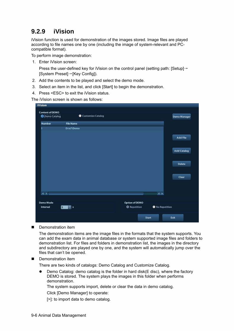
9-6 Animal Data Management
9.2.9 iVision iVision function is used for demonstration of the images stored. Image files are played according to file names one by one (including the image of system-relevant and PC-compatible format). To perform image demonstration: 1. Enter iVision screen:
Press the user-defined key for iVision on the control panel (setting path: [Setup]→[System Preset]→[Key Config]).
2. Add the contents to be played and select the demo mode. 3. Select an item in the list, and click [Start] to begin the demonstration. 4. Press <ESC> to exit the iVision status. The iVision screen is shown as follows:
Demonstration item
The demonstration items are the image files in the formats that the system supports. You can add the exam data in animal database or system supported image files and folders to demonstration list. For files and folders in demonstration list, the images in the directory and subdirectory are played one by one, and the system will automatically jump over the files that can’t be opened.
Demonstration item There are two kinds of catalogs: Demo Catalog and Customize Catalog.
Demo Catalog: demo catalog is the folder in hard disk(E disc), where the factory DEMO is stored. The system plays the images in this folder when performs demonstration. The system supports import, delete or clear the data in demo catalog. Click [Demo Manager] to operate: [>]: to import data to demo catalog.
Animal Data Management 9-7
[<]: to delete the selected data. [<<]: to delete all data.
Customize Catalog: what saved here is the catalog of the displayed image. The system plays the images in the catalog when performs demonstration. Operate the catalog by the buttons on the right: [Add File]: to add files to the file list. [Add Catalog]: to add catalog to the file list. [Delete]: to delete the selected file or catalog in the file list. [Clear]: to clear all the files or catalogs in the file list.
Demonstration mode Interval: refer to the interval time for demonstration, the adjusting range is 1~500s.
Option of Demo You can choose whether to repeat the demonstration or exit after a demonstration is completed.
9.2.10 Sending Image File On the image screen, select a stored image thumbnail, click the Send To Arrow on the
right corner of the image, the image can be sent to the external device, DVD recorder, DICOM storage server, DICOM print server, system connected printer and etc.
In the iStation screen, click the Send To Arrow; or, in Review screen, click [Send To] to send the selected image to the external devices.
For external memory devices (e.g. USB memory devices, and DVD or iStorage): a) PC format transfer: JPG/ AVI, BMP/ AVI, TIFF/ AVI. Where a single-frame image
is exported as JPG, TIFF or BMP, and the cine file exported as AVI. b) DCM format transfer: DCM( including single-frame DCM and multi-frame DCM). c) You can also select to export report.
For DICOM Storage or Print server, select the DICOM Storage or Print server. For a video printer, send images to the video printer connected with the system. For
a graph/ text printer, send the images to the default graph/ text printer.
9.3 Report Management Report storage:
The exam reports are stored under the directory of the exam of the animal. Importing, exporting and sending a report
In the iStation screen, select animal data, click (Restore) or (Backup) to import or export animal information, images and reports from or to an external memory device. See the following figure:
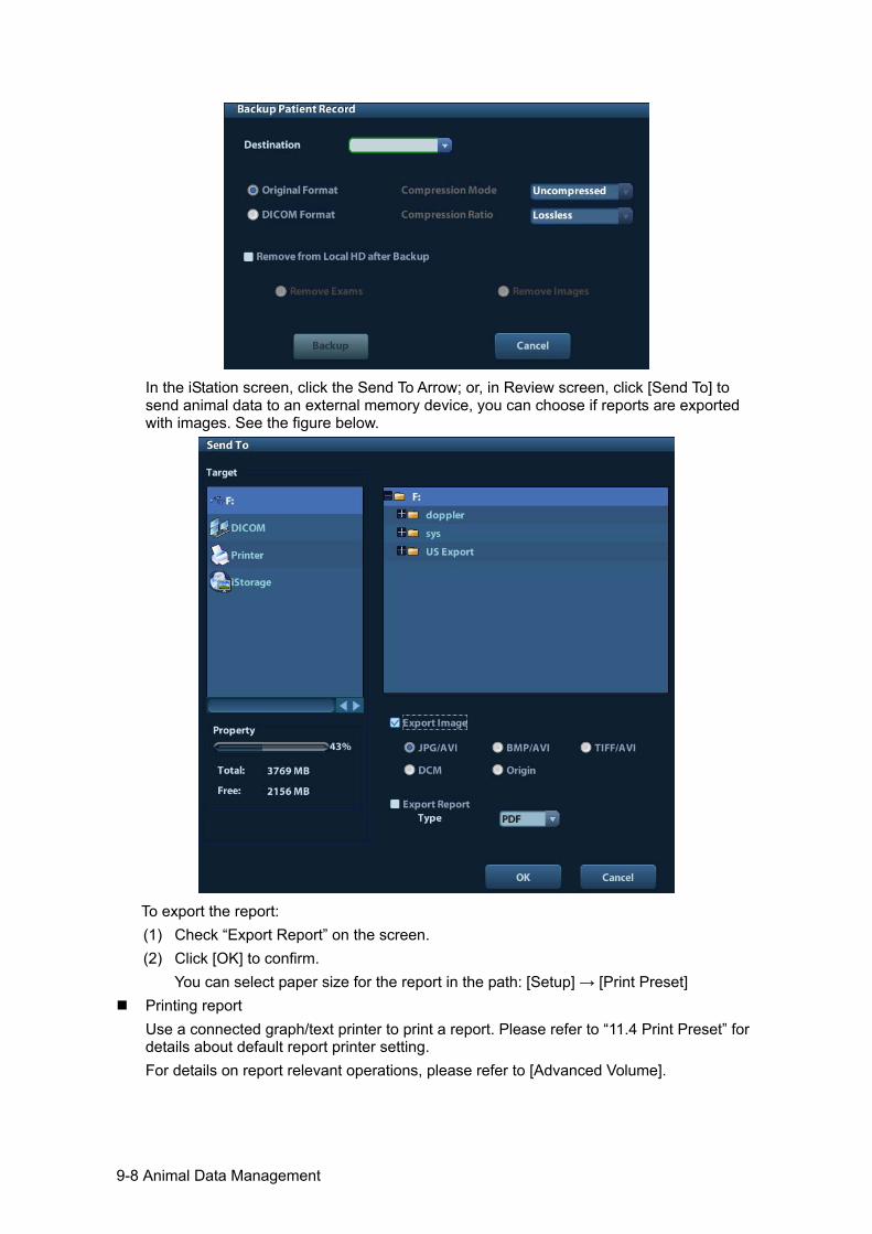
9-8 Animal Data Management
In the iStation screen, click the Send To Arrow; or, in Review screen, click [Send To] to send animal data to an external memory device, you can choose if reports are exported with images. See the figure below.
To export the report: (1) Check “Export Report” on the screen. (2) Click [OK] to confirm.
You can select paper size for the report in the path: [Setup] → [Print Preset] Printing report
Use a connected graph/text printer to print a report. Please refer to “11.4 Print Preset” for details about default report printer setting. For details on report relevant operations, please refer to [Advanced Volume].
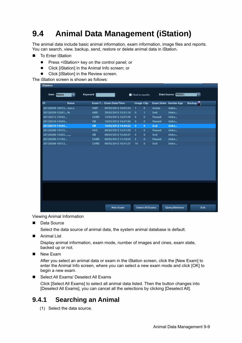
Animal Data Management 9-9
9.4 Animal Data Management (iStation) The animal data include basic animal information, exam information, image files and reports. You can search, view, backup, send, restore or delete animal data in iStation.
To Enter iStation Press <iStation> key on the control panel; or Click [iStation] in the Animal Info screen; or Click [iStation] in the Review screen.
The iStation screen is shown as follows:
Viewing Animal Information
Data Source Select the data source of animal data, the system animal database is default.
Animal List Display animal information, exam mode, number of images and cines, exam state, backed up or not.
New Exam After you select an animal data or exam in the iStation screen, click the [New Exam] to enter the Animal Info screen, where you can select a new exam mode and click [OK] to begin a new exam.
Select All Exams/ Deselect All Exams Click [Select All Exams] to select all animal data listed. Then the button changes into [Deselect All Exams], you can cancel all the selections by clicking [Deselect All].
9.4.1 Searching an Animal (1) Select the data source.
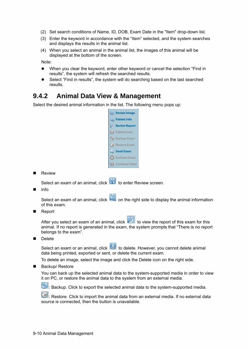
9-10 Animal Data Management
(2) Set search conditions of Name, ID, DOB, Exam Date in the "Item" drop-down list. (3) Enter the keyword in accordance with the “Item” selected, and the system searches
and displays the results in the animal list. (4) When you select an animal in the animal list, the images of this animal will be
displayed at the bottom of the screen. Note:
When you clear the keyword, enter other keyword or cancel the selection “Find in results”, the system will refresh the searched results.
Select “Find in results”, the system will do searching based on the last searched results.
9.4.2 Animal Data View & Management Select the desired animal information in the list. The following menu pops up:
Review
Select an exam of an animal, click to enter Review screen. Info
Select an exam of an animal, click on the right side to display the animal information of this exam.
Report
After you select an exam of an animal, click to view the report of this exam for this animal. If no report is generated in the exam, the system prompts that “There is no report belongs to the exam”.
Delete
Select an exam or an animal, click to delete. However, you cannot delete animal data being printed, exported or sent, or delete the current exam. To delete an image, select the image and click the Delete icon on the right side.
Backup/ Restore You can back up the selected animal data to the system-supported media in order to view it on PC, or restore the animal data to the system from an external media.
: Backup. Click to export the selected animal data to the system-supported media.
: Restore. Click to import the animal data from an external media. If no external data source is connected, then the button is unavailable.
Animal Data Management 9-11
Send To The system supports to send data to external memory devices or print.
Select the animal record, click in the menu to send exam data or images of the selected record.
Select the image, click the Send To Arrow to send the selected image. Send animal exam data to USB devices, DVD drive and iStorage. Send images to USB devices, DVD drive, DICOM storage server, DICOM printer,
video printer, text/ graph printer and iStorage. Send images with report to USB devices, DVD drive and iStorage. Format transfer is available when sending images to USB devices, DVD or
iStorage. See "9.2.10 Sending Image File" for details. Press <Shift> on the control panel to select more than one exam or image at one
time.
Activate exam
After you select an exam, which has been performed within 24 hours, click to activate the exam and load the basic animal information and measurement data to continue the exam. If you want to select an animal data in an external memory database to start a new exam or recover the exam, you have to first allow the system to load the animal data to the system’s animal database.
Continue Exam
Select an exam that is paused within 24 hours, click to activate the exam and load the basic animal information and measurement data to continue the exam. If you want to continue an exam which data lies in an external memory database, you have to first allow the system to load the animal data to the system’s animal database.
Recycle bin The recycle bin is used to store the deleted animal data, exam data and images (time lasts from deleting to system is powered off). The system supports recovery of those data from the recycle bin. NOTE: The recycle bin will be cleared after the system is powered off.
To recover the deleted animal data, click at the lower right corner of the screen (when the button is gray, the operation is unavailable) to enter the Animal Recycle Bin screen. (1) Select items to be recovered in the list. (2) Select operations:
Click [Restore Items] to restore the item back to iStation; Click [Delete] to delete the item permanently, and the item can never be restored
again; Click [Restore All Items] to restore all the items back to iStation; Click [Empty Recycle Bin] to empty the recycle bin and all items can never be
restored again. Click [Exit] to exit Recycle Bin screen and return to iStation.
9-12 Animal Data Management
9.5 Backing Up and Erasing Files through DVD Drive
The system supports DVD-RW to write data in CD/DVD and to read data from CD/DVD in PC. Support media: DVD±RW, CD-R/W.
To write data to a CD/DVD: (1) Put a CD/DVD in the tray.
(2) Select the data to be backed up, click or in the screen (in iStation or Review). Select the target drive in the Send To or Back Up Animal Record dialogue box.
(3) Click or [OK] to start writing with the symbol displays .
(4) After the writing process is completed, click to pop up the Disc Option dialogue box, and select [Eject] to eject the CD/DVD.
To erase data from a CD/DVD (1) Put the CD/DVD in the tray.
(2) Double-click the symbol to pop up the [Disc Option] screen, as shown in the figure below.
(3) Click [Erase] to erase data from a CD/DVD; (4) After the erasing process is completed, click [Eject] in the Disc Option dialogue box.
Note: Writing data using “Send To” supports PC format transfer function, while CD/DVD
written by “Backup” supports only system-relevant formats.
The symbol indicates that the input CD/DVD is damaged or with data of wrong format.
CAUTION: During the backup process, if a CD/DVD is forcibly taken out or you perform other operations, the backup process will fail or the system may malfunction.
NOTE: Directly removing a DVD-RW/DVD+RW drive may result in the damage of drive and/or the system, please refer to “3.6 Connecting/ Removing a USB Storage Device” for disconnection.
9.6 Task Manager Click at the lower right corner of the screen to pop up the following dialogue box:
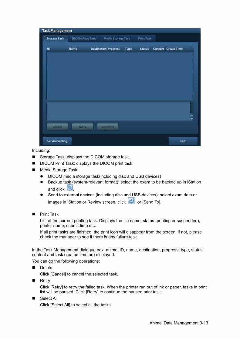
Animal Data Management 9-13
Including:
Storage Task: displays the DICOM storage task. DICOM Print Task: displays the DICOM print task. Media Storage Task:
DICOM media storage task(including disc and USB devices) Backup task (system-relevant format): select the exam to be backed up in iStation
and click . Send to external devices (including disc and USB devices): select exam data or
images in iStation or Review screen, click or [Send To].
Print Task List of the current printing task. Displays the file name, status (printing or suspended), printer name, submit time etc. If all print tasks are finished, the print icon will disappear from the screen, if not, please check the manager to see if there is any failure task.
In the Task Management dialogue box, animal ID, name, destination, progress, type, status, content and task created time are displayed. You can do the following operations:
Delete Click [Cancel] to cancel the selected task.
Retry Click [Retry] to retry the failed task. When the printer ran out of ink or paper, tasks in print list will be paused. Click [Retry] to continue the paused print task.
Select All Click [Select All] to select all the tasks.
9-14 Animal Data Management
Task Status Select the undergoing task, the system will display its detailed status information or error information.
When there is/are task(s) undergoing, the task management icon displays as , you can click the icon to check the process.
When there is/are task(s) failed, the task management icon displays as , you can click the icon to check the failure reason.
When the task management icon displays as , it means no task is undergoing or failure.
DICOM Service Setting Click [Service Setting] to enter DICOM preset. See section 10.3 DICOM Service.
9.7 Access Control 9.7.1 Access Setting The system support user type of:
Administrator The system administrator can view all animal data, such as animal information, image and report, etc.
Operator The operator can only view the exam information saved in the system and operated by himself or herself, such as animal information, image and report, etc. The operator cannot view the exam data operated by others.
Emergency operators are general ones, they can enter the system without entering password. But they can’t modify or delete the password.
9.7.2 Setting Access Control The system administrator can preset the access control, that is, if an operator has the right to access to the data in the system. The access control only can be set by the system administrator. Setting access control: 1. Open the “Admin” page through the path: [Setup]→[System Preset]→[Admin]. 2. If [Enable User Account Control] is selected, you need to login before accessing system
data. If unselected, you can access all the data without the authority.
9.7.3 System Login If [Enable User Account Control] is selected, you can access the data in the system only after you login the system. You need to enter user name and password in the following cases:
Before entering the system Changing user
As long as the system is in working status, you can enter the above screens without inputting user name and password repeatedly. You need to login again after system restart or dormancy.
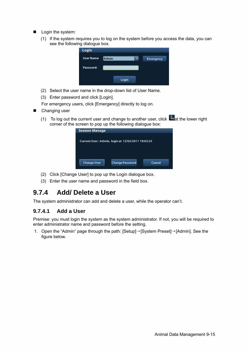
Animal Data Management 9-15
Login the system: (1) If the system requires you to log on the system before you access the data, you can
see the following dialogue box.
(2) Select the user name in the drop-down list of User Name. (3) Enter password and click [Login]. For emergency users, click [Emergency] directly to log on.
Changing user
(1) To log out the current user and change to another user, click at the lower right corner of the screen to pop up the following dialogue box:
(2) Click [Change User] to pop up the Login dialogue box. (3) Enter the user name and password in the field box.
9.7.4 Add/ Delete a User The system administrator can add and delete a user, while the operator can’t.
9.7.4.1 Add a User Premise: you must login the system as the system administrator. If not, you will be required to enter administrator name and password before the setting. 1. Open the “Admin” page through the path: [Setup]→[System Preset]→[Admin]. See the
figure below.
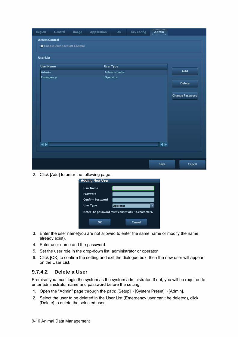
9-16 Animal Data Management
2. Click [Add] to enter the following page.
3. Enter the user name(you are not allowed to enter the same name or modify the name
already exist). 4. Enter user name and the password. 5. Set the user role in the drop-down list: administrator or operator. 6. Click [OK] to confirm the setting and exit the dialogue box, then the new user will appear
on the User List.
9.7.4.2 Delete a User Premise: you must login the system as the system administrator. If not, you will be required to enter administrator name and password before the setting. 1. Open the “Admin” page through the path: [Setup]→[System Preset]→[Admin]. 2. Select the user to be deleted in the User List (Emergency user can’t be deleted), click
[Delete] to delete the selected user.
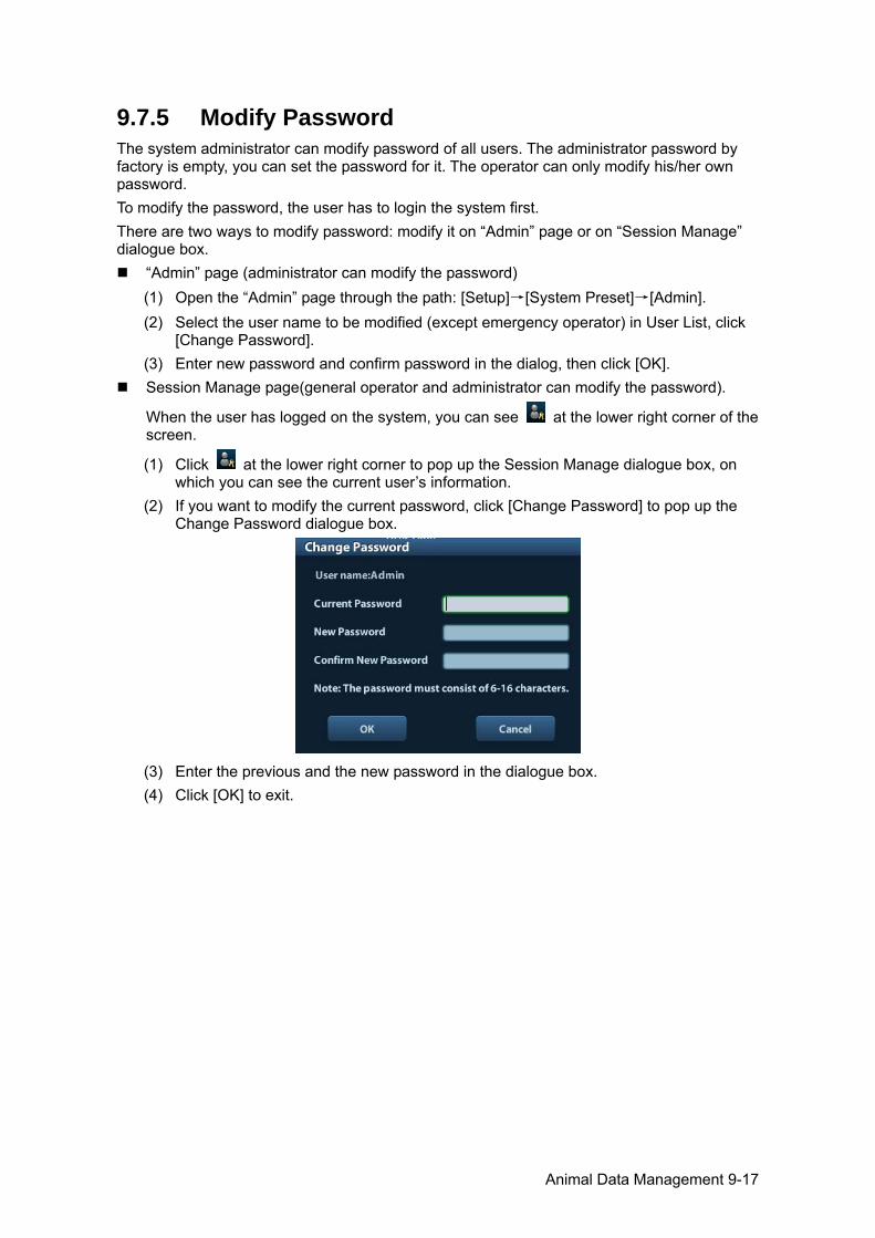
Animal Data Management 9-17
9.7.5 Modify Password The system administrator can modify password of all users. The administrator password by factory is empty, you can set the password for it. The operator can only modify his/her own password. To modify the password, the user has to login the system first. There are two ways to modify password: modify it on “Admin” page or on “Session Manage” dialogue box.
“Admin” page (administrator can modify the password) (1) Open the “Admin” page through the path: [Setup]→[System Preset]→[Admin]. (2) Select the user name to be modified (except emergency operator) in User List, click
[Change Password]. (3) Enter new password and confirm password in the dialog, then click [OK].
Session Manage page(general operator and administrator can modify the password).
When the user has logged on the system, you can see at the lower right corner of the screen.
(1) Click at the lower right corner to pop up the Session Manage dialogue box, on which you can see the current user’s information.
(2) If you want to modify the current password, click [Change Password] to pop up the Change Password dialogue box.
(3) Enter the previous and the new password in the dialogue box. (4) Click [OK] to exit.


DICOM 10-1
10 DICOM
NOTE: Before using DICOM, please read the electronic file DICOM CONFORMANCE STATEMENT along with the device.
This chapter is confined to the preset, connection verification and DICOM services of the DICOM-configured ultrasound machine, not including SCP configurations like PACS/ RIS/ HIS. The DICOM package is optional, so the description here is only applicable for the system configured with the DICOM package. This system supports the following DICOM functions:
DICOM Basic functions: DICOM verify connectivity, DICOM task management, DICOM storage, DICOM print, DICOM storage commitment, DICOM media storage (DICOMDIR review)
Workflows of DICOM preset and application are briefly described as follows: 1. DICOM preset (network preset, DICOM preset and DICOM service) 2. Verify connection. 3. DICOM Services (image storage, print, Worklist, storage commitment, media storage,
DICOMDIR review, task management). Abbr. used in this chapter:
Abbr. Descriptions
DICOM Digital Imaging and Communications in Medicine
AE Application Entity
PDU Protocol Data Unit
SCU Service Class User (DICOM client)
SCP Service Class Provider (DICOM server)
SOP Service-Object Pair
10.1 DICOM Preset 10.1.1 Network Preset NOTE DO Not edit IP address in Network Preset page as the network task is executed,
otherwise it fails. View if there is any undergoing task in task manager of the system.
Preset local TCP/IP settings. 1. Press <Setup> to enter the [Setup] menu. 2. Select [Network Preset].

10-2 DICOM
3. Local TCP/ IP preset items are described as follows:
Name Description
Current Net Adapter To select network connection mode.
DHCP / Static
DHCP: IP address will be automatically obtained from DNS server; Static: you need to enter the IP address.
IP Address IP address of the system.
Subnet Mask Used to set different network segment.
Gateway Used to set the gateway IP.
Note: The IP address of the system should not be occupied by other devices in the network,
or the DICOM function will fail. After you changed “Station Name”, you need to restart the system to make the setting
effective (press the power button and select “Shut Down” and restart the system after a while).
10.1.2 DICOM Preset To set the DICOM service and server properties. 1. Press <Setup> to enter the [Setup] menu. 2. Select [DICOM Preset].
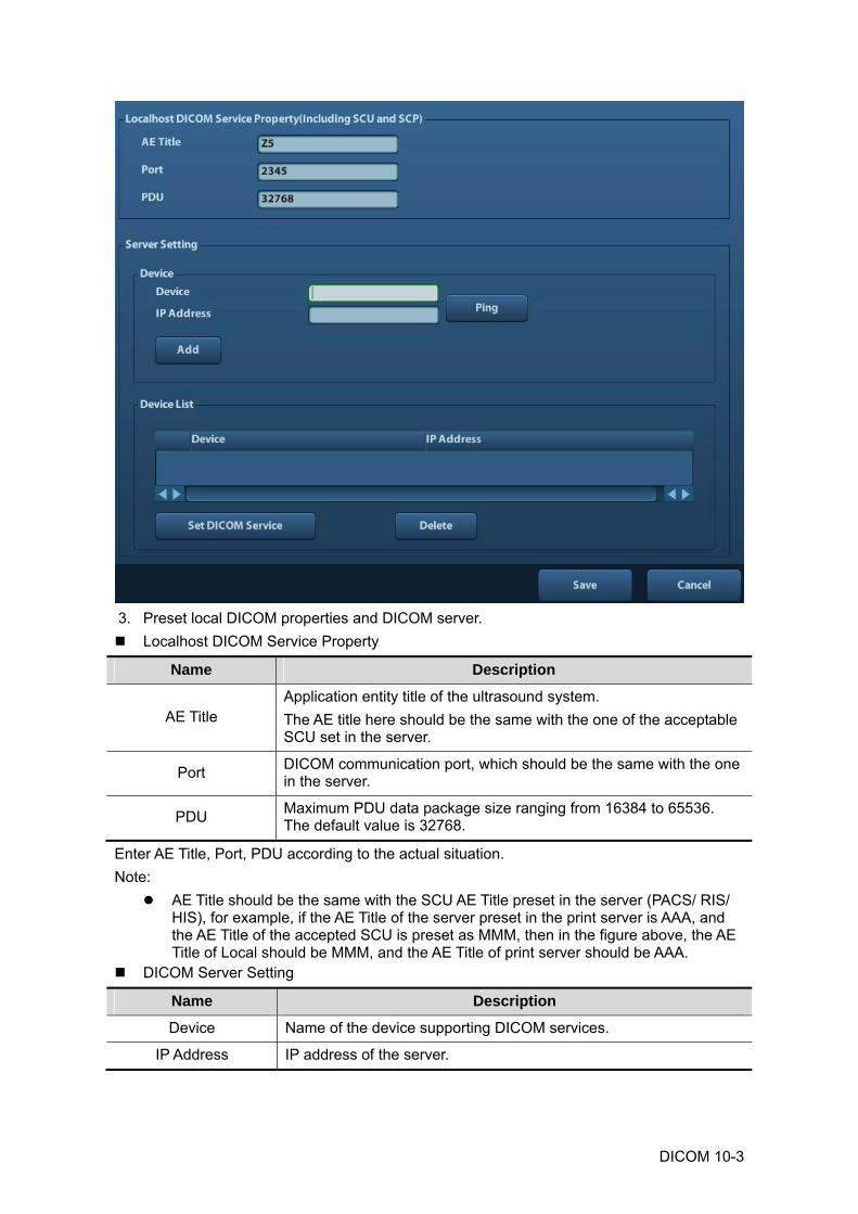
DICOM 10-3
3. Preset local DICOM properties and DICOM server. Localhost DICOM Service Property
Name Description
AE Title Application entity title of the ultrasound system. The AE title here should be the same with the one of the acceptable SCU set in the server.
Port DICOM communication port, which should be the same with the one in the server.
PDU Maximum PDU data package size ranging from 16384 to 65536. The default value is 32768.
Enter AE Title, Port, PDU according to the actual situation. Note:
AE Title should be the same with the SCU AE Title preset in the server (PACS/ RIS/ HIS), for example, if the AE Title of the server preset in the print server is AAA, and the AE Title of the accepted SCU is preset as MMM, then in the figure above, the AE Title of Local should be MMM, and the AE Title of print server should be AAA.
DICOM Server Setting
Name Description
Device Name of the device supporting DICOM services.
IP Address IP address of the server.
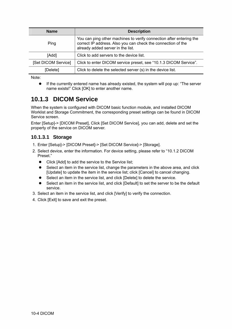
10-4 DICOM
Name Description
Ping You can ping other machines to verify connection after entering the correct IP address. Also you can check the connection of the already added server in the list.
[Add] Click to add servers to the device list.
[Set DICOM Service] Click to enter DICOM service preset, see “10.1.3 DICOM Service”.
[Delete] Click to delete the selected server (s) in the device list.
Note: If the currently entered name has already existed, the system will pop up: “The server
name exists!” Click [OK] to enter another name.
10.1.3 DICOM Service When the system is configured with DICOM basic function module, and installed DICOM Worklist and Storage Commitment, the corresponding preset settings can be found in DICOM Service screen. Enter [Setup]-> [DICOM Preset], Click [Set DICOM Service], you can add, delete and set the property of the service on DICOM server.
10.1.3.1 Storage 1. Enter [Setup]-> [DICOM Preset]-> [Set DICOM Service]-> [Storage]. 2. Select device, enter the information. For device setting, please refer to “10.1.2 DICOM
Preset.” Click [Add] to add the service to the Service list; Select an item in the service list, change the parameters in the above area, and click
[Update] to update the item in the service list; click [Cancel] to cancel changing. Select an item in the service list, and click [Delete] to delete the service. Select an item in the service list, and click [Default] to set the server to be the default
service. 3. Select an item in the service list, and click [Verify] to verify the connection. 4. Click [Exit] to save and exit the preset.
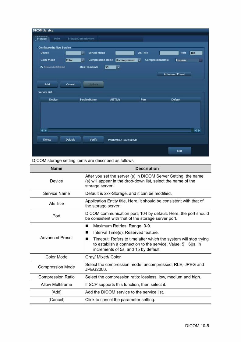
DICOM 10-5
DICOM storage setting items are described as follows:
Name Description
Device After you set the server (s) in DICOM Server Setting, the name (s) will appear in the drop-down list, select the name of the storage server.
Service Name Default is xxx-Storage, and it can be modified.
AE Title Application Entity title, Here, it should be consistent with that of the storage server.
Port DICOM communication port, 104 by default. Here, the port should be consistent with that of the storage server port.
Advanced Preset
Maximum Retries: Range: 0-9. Interval Time(s): Reserved feature. Timeout: Refers to time after which the system will stop trying
to establish a connection to the service. Value: 5-60s, in increments of 5s, and 15 by default.
Color Mode Gray/ Mixed/ Color
Compression Mode Select the compression mode: uncompressed, RLE, JPEG and JPEG2000.
Compression Ratio Select the compression ratio: lossless, low, medium and high.
Allow Multiframe If SCP supports this function, then select it.
[Add] Add the DICOM service to the service list.
[Cancel] Click to cancel the parameter setting.
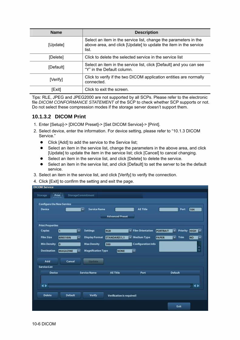
10-6 DICOM
Name Description
[Update] Select an item in the service list, change the parameters in the above area, and click [Update] to update the item in the service list.
[Delete] Click to delete the selected service in the service list
[Default] Select an item in the service list, click [Default] and you can see “Y” in the Default column.
[Verify] Click to verify if the two DICOM application entities are normally connected.
[Exit] Click to exit the screen.
Tips: RLE, JPEG and JPEG2000 are not supported by all SCPs. Please refer to the electronic file DICOM CONFORMANCE STATEMENT of the SCP to check whether SCP supports or not. Do not select these compression modes if the storage server doesn’t support them.
10.1.3.2 DICOM Print 1. Enter [Setup]-> [DICOM Preset]-> [Set DICOM Service]-> [Print]. 2. Select device, enter the information. For device setting, please refer to “10.1.3 DICOM
Service.” Click [Add] to add the service to the Service list; Select an item in the service list, change the parameters in the above area, and click
[Update] to update the item in the service list; click [Cancel] to cancel changing. Select an item in the service list, and click [Delete] to delete the service. Select an item in the service list, and click [Default] to set the server to be the default
service. 3. Select an item in the service list, and click [Verify] to verify the connection. 4. Click [Exit] to confirm the setting and exit the page.
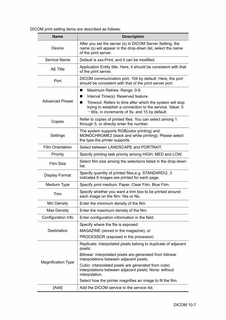
DICOM 10-7
DICOM print setting items are described as follows:
Name Description
Device After you set the server (s) in DICOM Server Setting, the name (s) will appear in the drop-down list, select the name of the print server.
Service Name Default is xxx-Print, and it can be modified.
AE Title Application Entity title. Here, it should be consistent with that of the print server.
Port DICOM communication port, 104 by default. Here, the port should be consistent with that of the print server port.
Advanced Preset
Maximum Retries: Range: 0-9. Interval Time(s): Reserved feature. Timeout: Refers to time after which the system will stop
trying to establish a connection to the service. Value: 5-60s, in increments of 5s, and 15 by default.
Copies Refer to copies of printed files. You can select among 1 through 5, or directly enter the number.
Settings The system supports RGB(color printing) and MONOCHROME2 (black and white printing). Please select the type the printer supports.
Film Orientation Select between LANDSCAPE and PORTRAIT.
Priority Specify printing task priority among HIGH, MED and LOW.
Film Size Select film size among the selections listed in the drop-down list.
Display Format Specify quantity of printed files,e.g. STANDARD\2, 3 indicates 6 images are printed for each page.
Medium Type Specify print medium: Paper, Clear Film, Blue Film.
Trim Specify whether you want a trim box to be printed around each image on the film: Yes or No.
Min Density Enter the minimum density of the film
Max Density Enter the maximum density of the film.
Configuration Info Enter configuration information in the field.
Destination Specify where the file is exposed: MAGAZINE (stored in the magazine), or PROCESSOR (exposed in the processor)
Magnification Type
Replicate: interpolated pixels belong to duplicate of adjacent pixels; Bilinear: interpolated pixels are generated from bilinear interpolations between adjacent pixels; Cubic: interpolated pixels are generated from cubic interpolations between adjacent pixels; None: without interpolation. Select how the printer magnifies an image to fit the film.
[Add] Add the DICOM service to the service list.
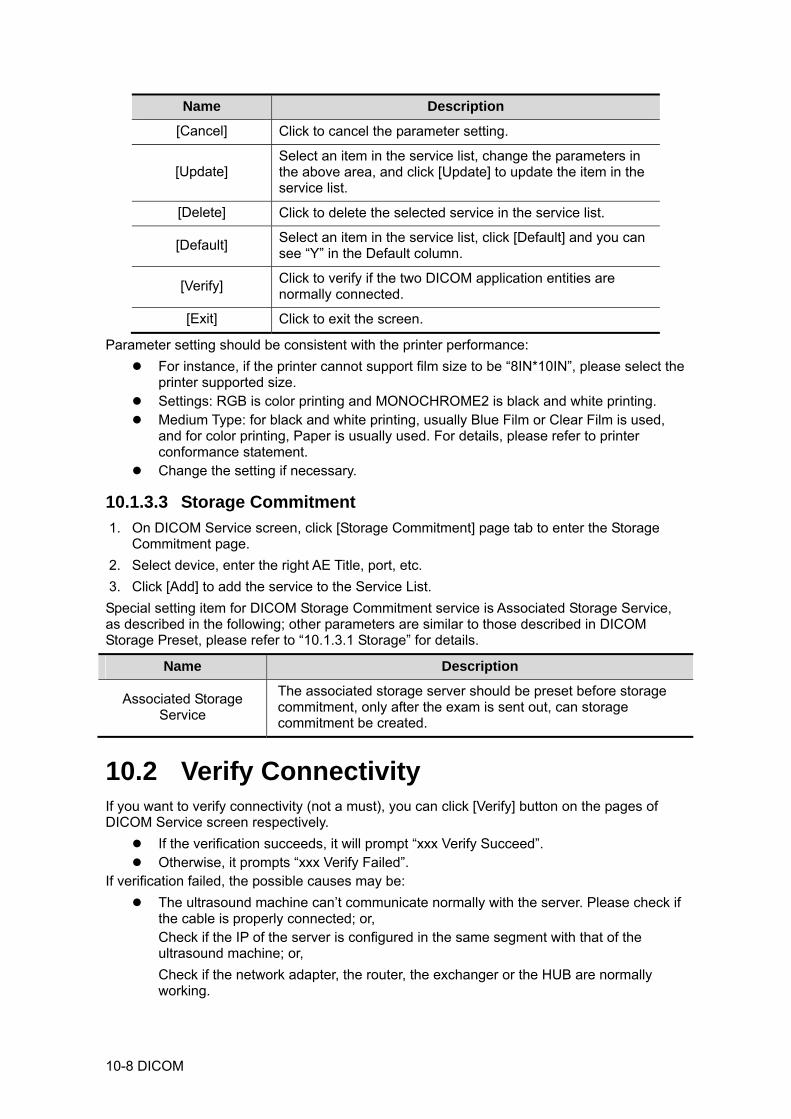
10-8 DICOM
Name Description
[Cancel] Click to cancel the parameter setting.
[Update] Select an item in the service list, change the parameters in the above area, and click [Update] to update the item in the service list.
[Delete] Click to delete the selected service in the service list.
[Default] Select an item in the service list, click [Default] and you can see “Y” in the Default column.
[Verify] Click to verify if the two DICOM application entities are normally connected.
[Exit] Click to exit the screen.
Parameter setting should be consistent with the printer performance: For instance, if the printer cannot support film size to be “8IN*10IN”, please select the
printer supported size. Settings: RGB is color printing and MONOCHROME2 is black and white printing. Medium Type: for black and white printing, usually Blue Film or Clear Film is used,
and for color printing, Paper is usually used. For details, please refer to printer conformance statement.
Change the setting if necessary.
10.1.3.3 Storage Commitment 1. On DICOM Service screen, click [Storage Commitment] page tab to enter the Storage
Commitment page. 2. Select device, enter the right AE Title, port, etc. 3. Click [Add] to add the service to the Service List. Special setting item for DICOM Storage Commitment service is Associated Storage Service, as described in the following; other parameters are similar to those described in DICOM Storage Preset, please refer to “10.1.3.1 Storage” for details.
Name Description
Associated Storage Service
The associated storage server should be preset before storage commitment, only after the exam is sent out, can storage commitment be created.
10.2 Verify Connectivity If you want to verify connectivity (not a must), you can click [Verify] button on the pages of DICOM Service screen respectively.
If the verification succeeds, it will prompt “xxx Verify Succeed”. Otherwise, it prompts “xxx Verify Failed”.
If verification failed, the possible causes may be: The ultrasound machine can’t communicate normally with the server. Please check if
the cable is properly connected; or, Check if the IP of the server is configured in the same segment with that of the ultrasound machine; or, Check if the network adapter, the router, the exchanger or the HUB are normally working.
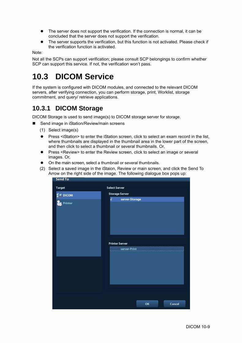
DICOM 10-9
The server does not support the verification. If the connection is normal, it can be concluded that the server does not support the verification.
The server supports the verification, but this function is not activated. Please check if the verification function is activated.
Note: Not all the SCPs can support verification; please consult SCP belongings to confirm whether SCP can support this service. If not, the verification won’t pass.
10.3 DICOM Service If the system is configured with DICOM modules, and connected to the relevant DICOM servers, after verifying connection, you can perform storage, print, Worklist, storage commitment, and query/ retrieve applications.
10.3.1 DICOM Storage DICOM Storage is used to send image(s) to DICOM storage server for storage.
Send image in iStation/Review/main screens (1) Select image(s)
Press <iStation> to enter the iStation screen, click to select an exam record in the list, where thumbnails are displayed in the thumbnail area in the lower part of the screen, and then click to select a thumbnail or several thumbnails. Or,
Press <Review> to enter the Review screen, click to select an image or several images. Or,
On the main screen, select a thumbnail or several thumbnails. (2) Select a saved image in the iStaion, Review or main screen, and click the Send To
Arrow on the right side of the image. The following dialogue box pops up:
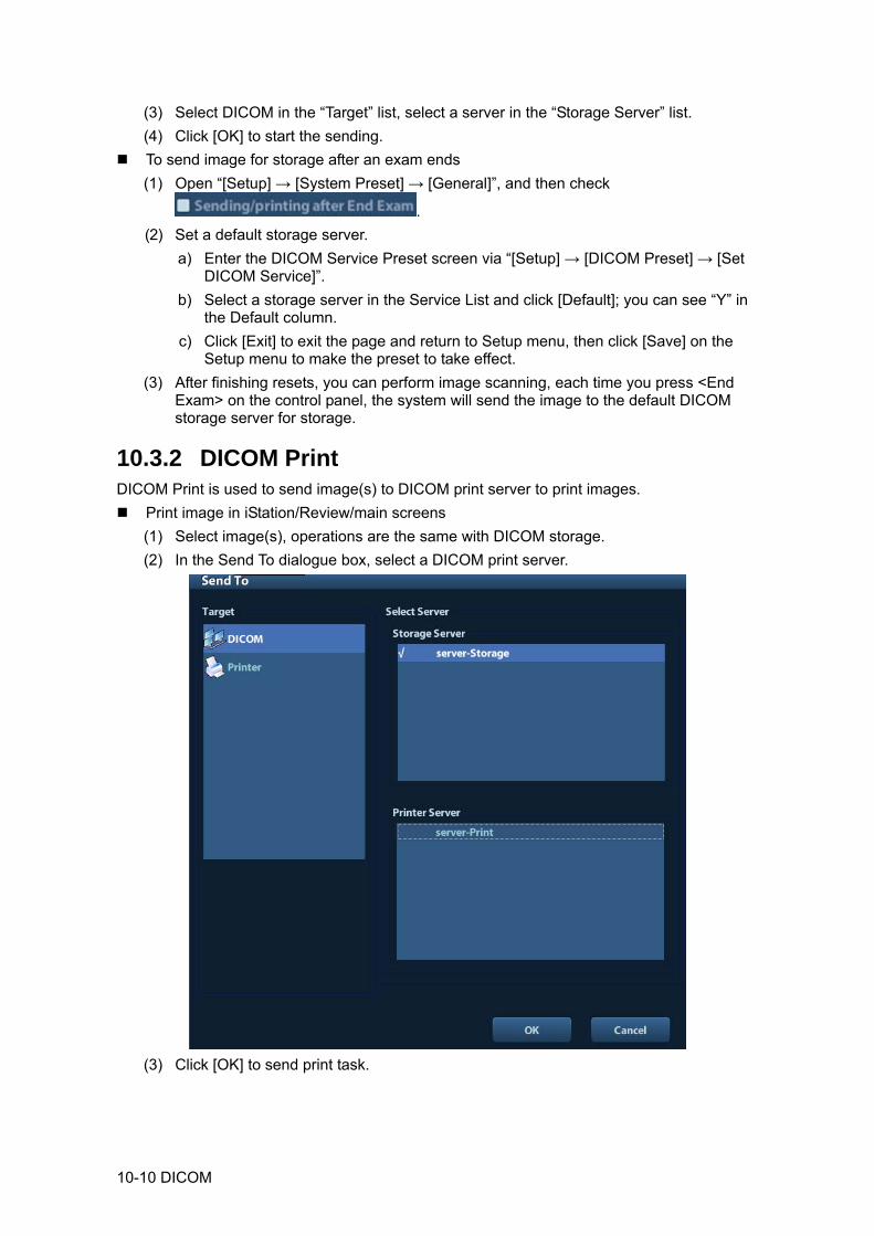
10-10 DICOM
(3) Select DICOM in the “Target” list, select a server in the “Storage Server” list. (4) Click [OK] to start the sending.
To send image for storage after an exam ends (1) Open “[Setup] → [System Preset] → [General]”, and then check
. (2) Set a default storage server.
a) Enter the DICOM Service Preset screen via “[Setup] → [DICOM Preset] → [Set DICOM Service]”.
b) Select a storage server in the Service List and click [Default]; you can see “Y” in the Default column.
c) Click [Exit] to exit the page and return to Setup menu, then click [Save] on the Setup menu to make the preset to take effect.
(3) After finishing resets, you can perform image scanning, each time you press <End Exam> on the control panel, the system will send the image to the default DICOM storage server for storage.
10.3.2 DICOM Print DICOM Print is used to send image(s) to DICOM print server to print images.
Print image in iStation/Review/main screens (1) Select image(s), operations are the same with DICOM storage. (2) In the Send To dialogue box, select a DICOM print server.
(3) Click [OK] to send print task.

DICOM 10-11
To print image for storage after an exam ends (1) Open “[Setup] → [System Preset] → [General]”, and then check
. (2) Set a default print server.
a) Enter the DICOM Service Preset screen via “[Setup] → [DICOM Preset] → [DICOM Service]”.
b) Click [Print] to open the Print page. c) Select a Print server in the Service List and click [Default]; you can see “Y” is
marked in the Default column. d) Click [Exit] to exit the page and return to Setup menu, then click [Save] on the
Setup menu to make the preset to take effect. (3) After finishing presets, you can perform image scanning, each time you press <End
Exam> on the control panel, the system will send the image to the default DICOM print server for printing.
10.3.3 Storage Commitment Storage commitment is used to make sure the images are successfully stored in the DICOM server. Before storage commitment, you should set a default storage commitment server.
Storage commitment after sending images on iStation screen (1) Open iStation screen: press <iStation> or press <Patient> and click [iStation].
(2) Select an exam record (image (s) is/are stored in the exam record), click to open the Send To dialogue box.
(3) Click to select “DICOM” in the “Target” box on the left side, then select the DICOM storage server in the “Storage Server” box on the right side.
(4) Click [OK] to start sending. The system will send all the images stored in the exam record to the storage server, meanwhile, it will send storage commitment to the storage commitment server.
To send storage commitment after an exam ends (1) Open [Setup] -> [System Preset]-> [General], and then select [Sending/ Printing
after End Exam] in the Animal Info area. (2) Set the default storage server and storage commitment server.
a) Enter the DICOM Service Preset screen via “[Setup] -> [DICOM Preset] -> [Set DICOM Service]”.
b) Select a server in the Service List of Storage page and Storage Commitment page and click [Default]; you can see “Y” is marked in the Default column.
c) Click [Exit] to exit the page and return to Setup menu, then click [Save] on the Setup menu to make the preset to take effect.
(3) When finished the presets, you can perform image scanning, each time you press <End Exam> on the control panel, the system will send the image to the default DICOM storage server for storage and send storage commitment to storage commitment server.
If images are successfully sent to the storage server, the storage commitment server will return information about the successful image storage. In the iStation screen, you will see there is a tick “√” marked in the list below . Tips: Storage commitment is confined to the whole exam; not each image sending can be indicated.
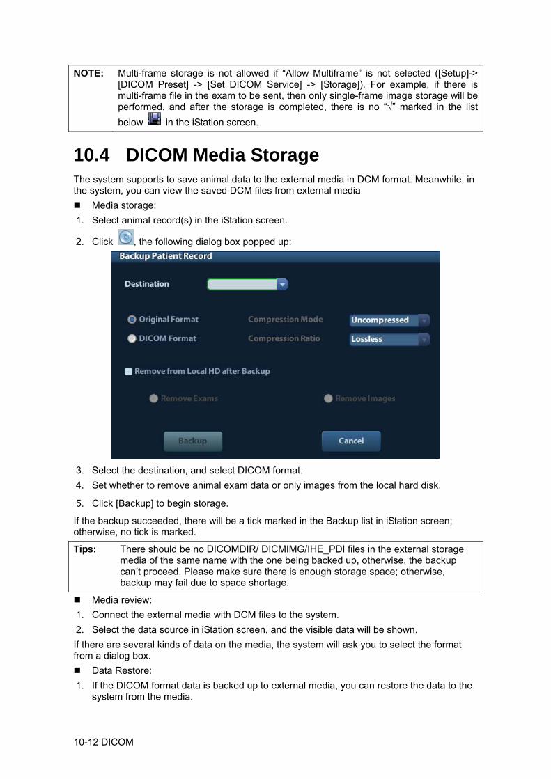
10-12 DICOM
NOTE: Multi-frame storage is not allowed if “Allow Multiframe” is not selected ([Setup]-> [DICOM Preset] -> [Set DICOM Service] -> [Storage]). For example, if there is multi-frame file in the exam to be sent, then only single-frame image storage will be performed, and after the storage is completed, there is no “√” marked in the list below in the iStation screen.
10.4 DICOM Media Storage The system supports to save animal data to the external media in DCM format. Meanwhile, in the system, you can view the saved DCM files from external media
Media storage: 1. Select animal record(s) in the iStation screen.
2. Click , the following dialog box popped up:
3. Select the destination, and select DICOM format. 4. Set whether to remove animal exam data or only images from the local hard disk.
5. Click [Backup] to begin storage.
If the backup succeeded, there will be a tick marked in the Backup list in iStation screen; otherwise, no tick is marked.
Tips: There should be no DICOMDIR/ DICMIMG/IHE_PDI files in the external storage media of the same name with the one being backed up, otherwise, the backup can’t proceed. Please make sure there is enough storage space; otherwise, backup may fail due to space shortage.
Media review: 1. Connect the external media with DCM files to the system. 2. Select the data source in iStation screen, and the visible data will be shown. If there are several kinds of data on the media, the system will ask you to select the format from a dialog box.
Data Restore: 1. If the DICOM format data is backed up to external media, you can restore the data to the
system from the media.

DICOM 10-13
2. Review the data stored in the external media. 3. Select the data to be restored in iStation.
4. Click in the iStation screen.
NOTE: Only the system accessible media can be selected.
10.5 DICOM Task Manager DICOM Task Management is used to view task progress or manage tasks after sending images for storage, print, or media storage. For details on tast manager, see 9.6 Task Manager.

Setup 11-1
11 Setup
The Setup function is designed to set the configuration parameters of operating the system and maintaining user workflow setup data. The setup data of the user and system are stored to the hard drive, and should be backed up to CD/DVD or USB memory devices.
CAUTION: When the setup data is changed, be sure to save the preferences according to the methods described in this chapter. Mindray is not responsible for the loss of the setup data.
To enter Setup: Press the <Setup> to enter Setup.
To exit Setup:
Click [Save] on the Setup page to close the Setup menu, and the parameter settings is saved. Click [Cancel] or press <Esc> on the control panel to exit the setup.
11.1 System Preset Click [System Preset] on the Setup menu, you can preset:
Page Description
Region To set the hospital name, language, time zone, time format, system date/time, logo and so on.
General To set animal information, exam setup, animal management, storage, system dormancy, operation log and so on.
Image To set some general parameters in imaging modes.
Application To set the measure ruler, follicle etc..
Key Config To assign functions to footswitch and user-defined keys.
Admin To set the user account control relevant information.
11.1.1 Region Open the Region page via [Setup]-> [System Preset]-> [Region], as shown in the figure table.
Item Description
Hospital Information To set the hospital relevant information like name, address, telephone and so on.
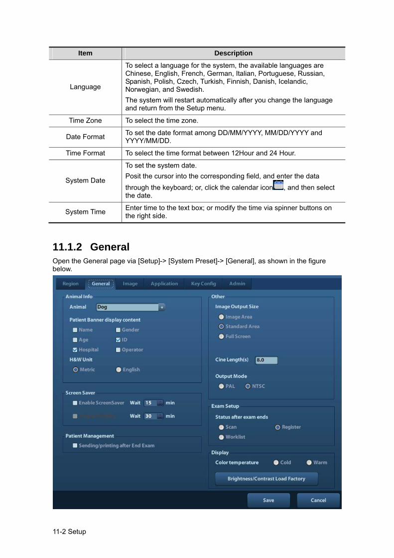
11-2 Setup
Item Description
Language
To select a language for the system, the available languages are Chinese, English, French, German, Italian, Portuguese, Russian, Spanish, Polish, Czech, Turkish, Finnish, Danish, Icelandic, Norwegian, and Swedish. The system will restart automatically after you change the language and return from the Setup menu.
Time Zone To select the time zone.
Date Format To set the date format among DD/MM/YYYY, MM/DD/YYYY and YYYY/MM/DD.
Time Format To select the time format between 12Hour and 24 Hour.
System Date
To set the system date. Posit the cursor into the corresponding field, and enter the data through the keyboard; or, click the calendar icon , and then select the date.
System Time Enter time to the text box; or modify the time via spinner buttons on the right side.
11.1.2 General Open the General page via [Setup]-> [System Preset]-> [General], as shown in the figure below.
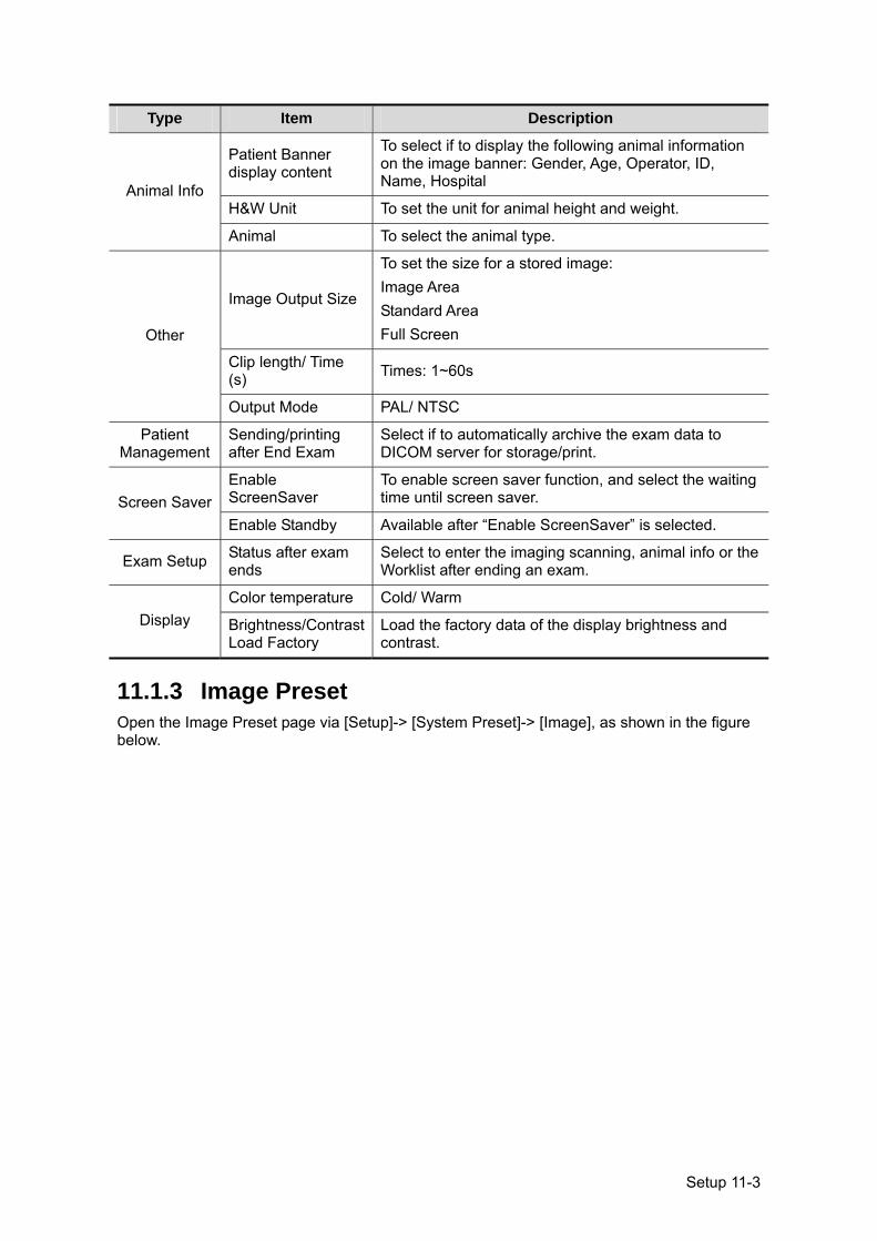
Setup 11-3
Type Item Description
Animal Info
Patient Banner display content
To select if to display the following animal information on the image banner: Gender, Age, Operator, ID, Name, Hospital
H&W Unit To set the unit for animal height and weight.
Animal To select the animal type.
Other
Image Output Size
To set the size for a stored image: Image Area Standard Area Full Screen
Clip length/ Time (s) Times: 1~60s
Output Mode PAL/ NTSC
Patient Management
Sending/printing after End Exam
Select if to automatically archive the exam data to DICOM server for storage/print.
Screen Saver Enable ScreenSaver
To enable screen saver function, and select the waiting time until screen saver.
Enable Standby Available after “Enable ScreenSaver” is selected.
Exam Setup Status after exam ends
Select to enter the imaging scanning, animal info or the Worklist after ending an exam.
Display Color temperature Cold/ Warm
Brightness/Contrast Load Factory
Load the factory data of the display brightness and contrast.
11.1.3 Image Preset Open the Image Preset page via [Setup]-> [System Preset]-> [Image], as shown in the figure below.
11-4 Setup
Type Item Description
Reset Config Probe To set the default probe model for the system.
Freeze Config Status after Freeze To set the system status after image is frozen.
Image
Steer
To set the steer mode in B+ Color +PW imaging mode.C&PW: select to adjust the sample volume in color mode and sample line in PW mode together. C/PW: select to adjust the sample volume in color mode and sample line in PW mode individually.
Auto Invert The spectrum can automatically invert when the color flow is steered to a certain angle, thus accommodating operator’s habit of distinguishing flow direction.
Cine Memory To set the cine memory splitting type.
iScape Ruler Display
To set if to display the iScape ruler on iScape imaging mode.
11.1.4 Application Open the Meas page via [Setup]-> [System Preset]-> [Application]. Through the page, you can set the measure ruler, follicle and relevant information. For details, please refer to the Operator’s Manual [Advanced Volume]
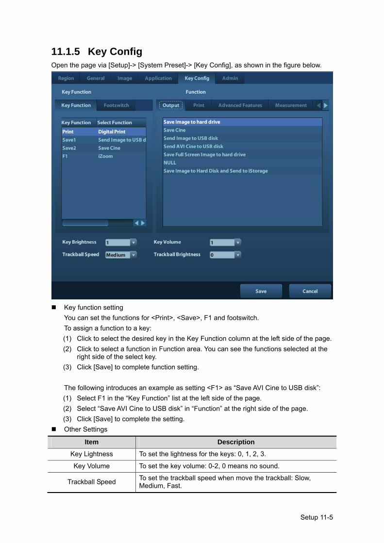
Setup 11-5
11.1.5 Key Config Open the page via [Setup]-> [System Preset]-> [Key Config], as shown in the figure below.
Key function setting
You can set the functions for <Print>, <Save>, F1 and footswitch. To assign a function to a key: (1) Click to select the desired key in the Key Function column at the left side of the page. (2) Click to select a function in Function area. You can see the functions selected at the
right side of the select key. (3) Click [Save] to complete function setting. The following introduces an example as setting <F1> as “Save AVI Cine to USB disk”: (1) Select F1 in the “Key Function” list at the left side of the page. (2) Select “Save AVI Cine to USB disk” in “Function” at the right side of the page. (3) Click [Save] to complete the setting.
Other Settings
Item Description
Key Lightness To set the lightness for the keys: 0, 1, 2, 3.
Key Volume To set the key volume: 0-2, 0 means no sound.
Trackball Speed To set the trackball speed when move the trackball: Slow, Medium, Fast.
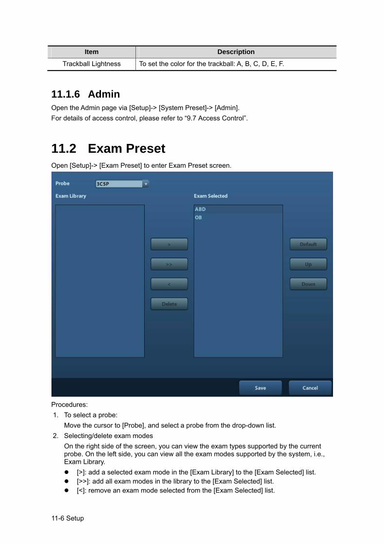
11-6 Setup
Item Description
Trackball Lightness To set the color for the trackball: A, B, C, D, E, F.
11.1.6 Admin Open the Admin page via [Setup]-> [System Preset]-> [Admin]. For details of access control, please refer to “9.7 Access Control”.
11.2 Exam Preset Open [Setup]-> [Exam Preset] to enter Exam Preset screen.
Procedures: 1. To select a probe:
Move the cursor to [Probe], and select a probe from the drop-down list. 2. Selecting/delete exam modes
On the right side of the screen, you can view the exam types supported by the current probe. On the left side, you can view all the exam modes supported by the system, i.e., Exam Library.
[>]: add a selected exam mode in the [Exam Library] to the [Exam Selected] list. [>>]: add all exam modes in the library to the [Exam Selected] list. [<]: remove an exam mode selected from the [Exam Selected] list.
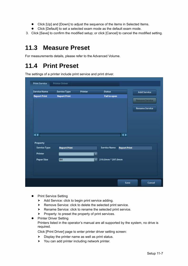
Setup 11-7
Click [Up] and [Down] to adjust the sequence of the items in Selected Items. Click [Default] to set a selected exam mode as the default exam mode.
3. Click [Save] to confirm the modified setup; or click [Cancel] to cancel the modified setting.
11.3 Measure Preset For measurements details, please refer to the Advanced Volume.
11.4 Print Preset The settings of a printer include print service and print driver.
Print Service Setting Add Service: click to begin print service adding. Remove Service: click to delete the selected print service. Rename Service: click to rename the selected print service. Property: to preset the property of print services.
Printer Driver Setting Printers listed in the operator’s manual are all supported by the system, no drive is required. Click [Print Driver] page to enter printer driver setting screen:
Display the printer name as well as print status. You can add printer including network printer.
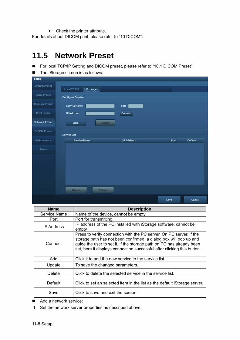
11-8 Setup
Check the printer attribute. For details about DICOM print, please refer to “10 DICOM”.
11.5 Network Preset For local TCP/IP Setting and DICOM preset, please refer to “10.1 DICOM Preset”. The iStorage screen is as follows:
Name Description
Service Name Name of the device, cannot be empty Port Port for transmitting.
IP Address IP address of the PC installed with iStorage software, cannot be empty
Connect
Press to verify connection with the PC server. On PC server, if the storage path has not been confirmed, a dialog box will pop up and guide the user to set it. If the storage path on PC has already been set, here it displays connection successful after clicking this button.
Add Click it to add the new service to the service list. Update To save the changed parameters.
Delete Click to delete the selected service in the service list.
Default Click to set an selected item in the list as the default iStorage server.
Save Click to save and exit the screen.
Add a network service: 1. Set the network server properties as described above.
Setup 11-9
2. Click [Add] to add the service to the Service list; 3. Select the added service in the service list, you can delete it. Modify a network service:
1. Select the service to be updated in the service list. 2. You can see properties in the Configure Service area. 3. Modify the parameters and click [Update] to update setting. Tips: in order to make network storage function normally, setting of the sharing folder of the PC server in advance is a must, e.g. machine name, IP address, should be confirmed at first. You can send exam data of images to iStorage server by UltraAssist. For details about this feature, please refer to the UltraAssist manual.
11.6 Maintenance In the Setup menu, select [Maintenance] enter the screen.
11.6.1 Option The system enters Option page after you enter the Maintenance screen. In Option list, the system lists out all the system supported options and the installation status (Not installed or Installed).
Install and uninstall Click [Install] to begin the installation of a disabled option. Click [Uninstall] to begin the un-installation of an already installed option.
Trial Select the option item in the list to see the information on the Comment region on the right. For functions that are not configured, you can use the function for free for 3 months.
Click to select the function(s) and click [Trial]. Tips: Every trial option can be used only once. Please refer to the dependence relationship between options in chapter “2.5.3 Options”.
Please contact Mindray Customer Service Department or sales representative for details.
11.6.2 Other Settings Type Item Description
Log Export Log Export the operation log.
Upload Log Upload the operation log.
Preset Manager
Load Factory Local factory default settings.
Export Export preset data to disk.
Import Import the preset data into the system.
11.7 System Information Click [About] in the Setup menu to enter the system information screen. (The information varies depending upon the system configurations and version.)
About Lists product name, hardware version and other information.

11-10 Setup
About Detail Lists version information of the software, hardware and other modules.
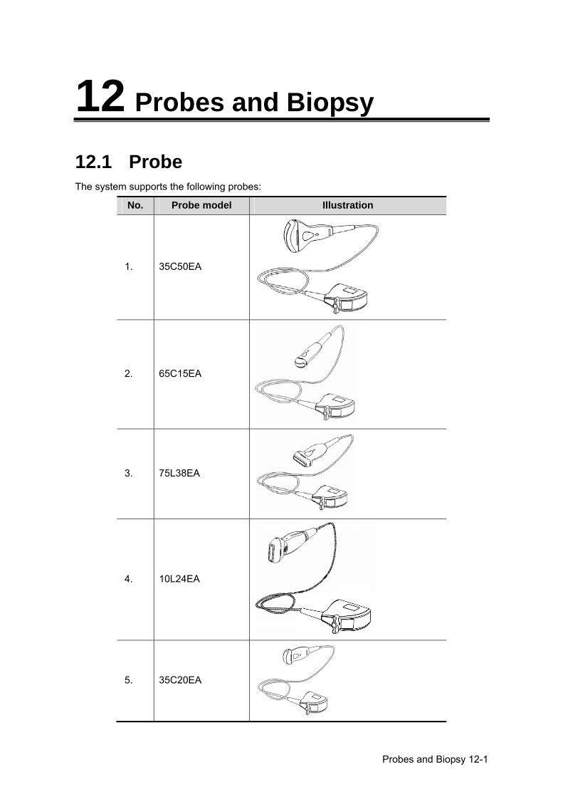
Probes and Biopsy 12-1
12 Probes and Biopsy
12.1 Probe The system supports the following probes:
No. Probe model Illustration
1. 35C50EA
2. 65C15EA
3. 75L38EA
4. 10L24EA
5. 35C20EA
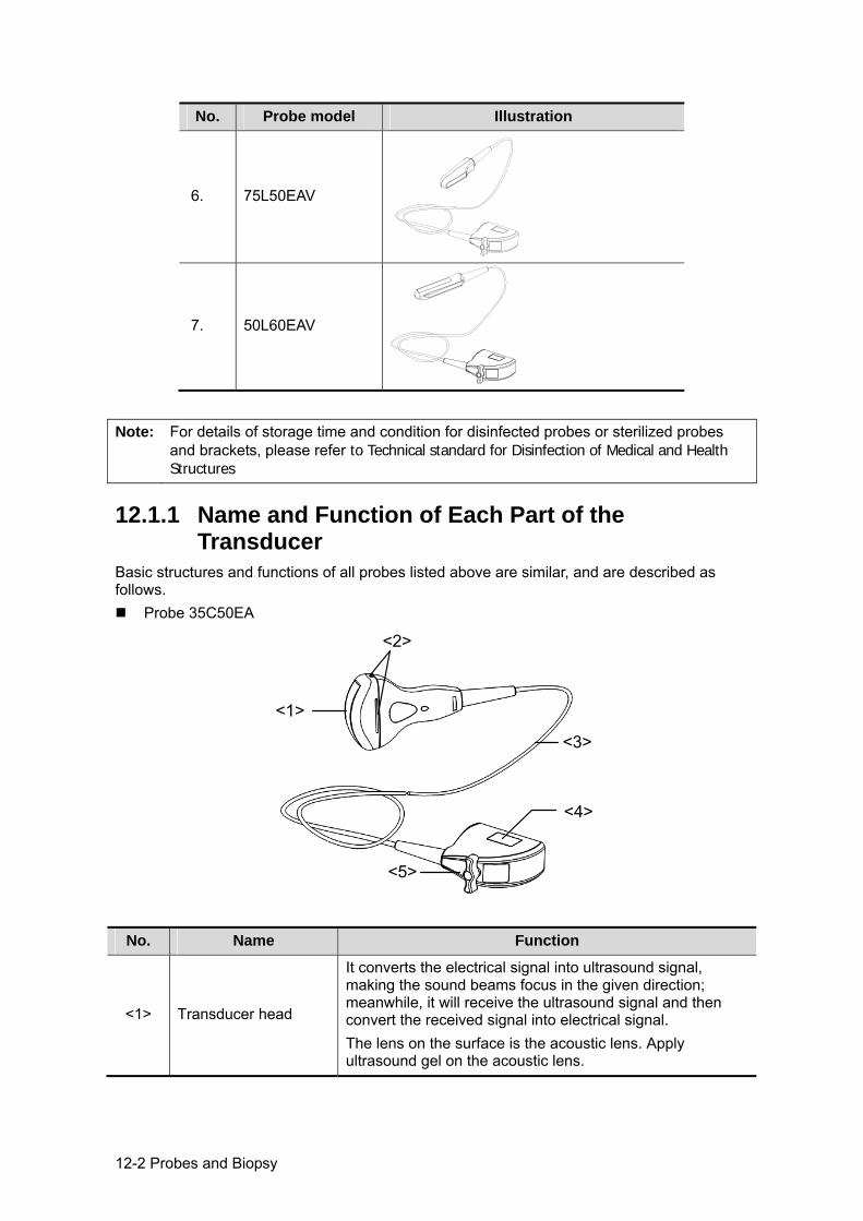
12-2 Probes and Biopsy
No. Probe model Illustration
6. 75L50EAV
7. 50L60EAV
Note: For details of storage time and condition for disinfected probes or sterilized probes and brackets, please refer to Technical standard for Disinfection of Medical and Health Structures
12.1.1 Name and Function of Each Part of the Transducer
Basic structures and functions of all probes listed above are similar, and are described as follows.
Probe 35C50EA
<1>
<2>
<3>
<4>
<5>
No. Name Function
<1> Transducer head
It converts the electrical signal into ultrasound signal, making the sound beams focus in the given direction; meanwhile, it will receive the ultrasound signal and then convert the received signal into electrical signal. The lens on the surface is the acoustic lens. Apply ultrasound gel on the acoustic lens.
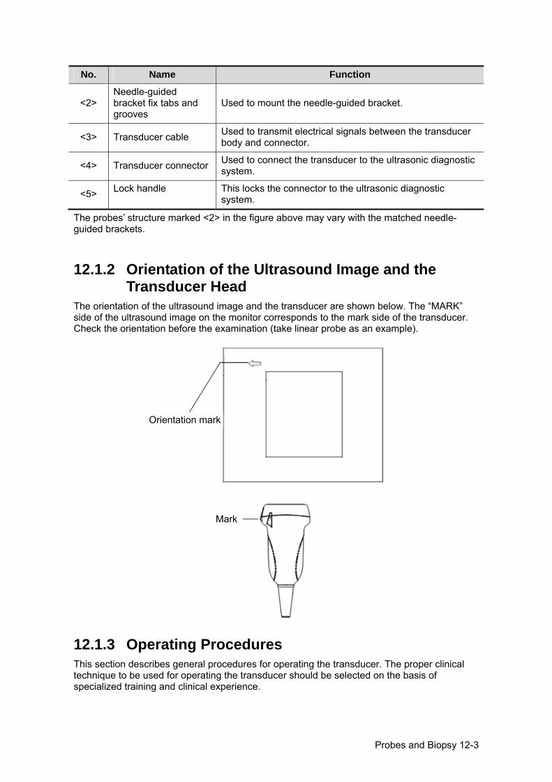
Probes and Biopsy 12-3
No. Name Function
<2> Needle-guided bracket fix tabs and grooves
Used to mount the needle-guided bracket.
<3> Transducer cable Used to transmit electrical signals between the transducer body and connector.
<4> Transducer connector Used to connect the transducer to the ultrasonic diagnostic system.
<5> Lock handle This locks the connector to the ultrasonic diagnostic system.
The probes’ structure marked <2> in the figure above may vary with the matched needle-guided brackets.
12.1.2 Orientation of the Ultrasound Image and the Transducer Head
The orientation of the ultrasound image and the transducer are shown below. The “MARK” side of the ultrasound image on the monitor corresponds to the mark side of the transducer. Check the orientation before the examination (take linear probe as an example).
12.1.3 Operating Procedures This section describes general procedures for operating the transducer. The proper clinical technique to be used for operating the transducer should be selected on the basis of specialized training and clinical experience.
Mark
Orientation mark
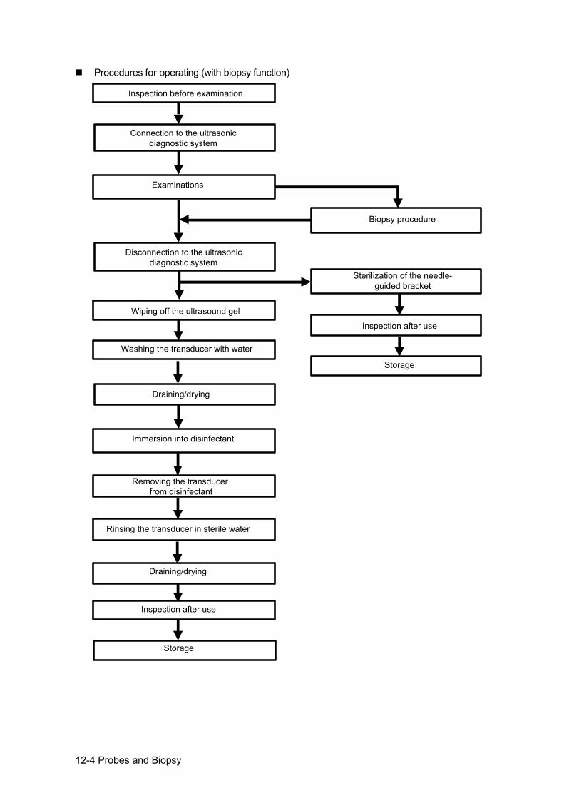
12-4 Probes and Biopsy
Procedures for operating (with biopsy function)
Inspection before examination
Connection to the ultrasonic diagnostic system
Examinations
Biopsy procedure
Wiping off the ultrasound gel
Washing the transducer with water
Draining/drying
Immersion into disinfectant
Draining/drying
Inspection after use
Storage
Disconnection to the ultrasonic diagnostic system
Sterilization of the needle-guided bracket
Inspection after use
Storage
Rinsing the transducer in sterile water
Removing the transducer from disinfectant
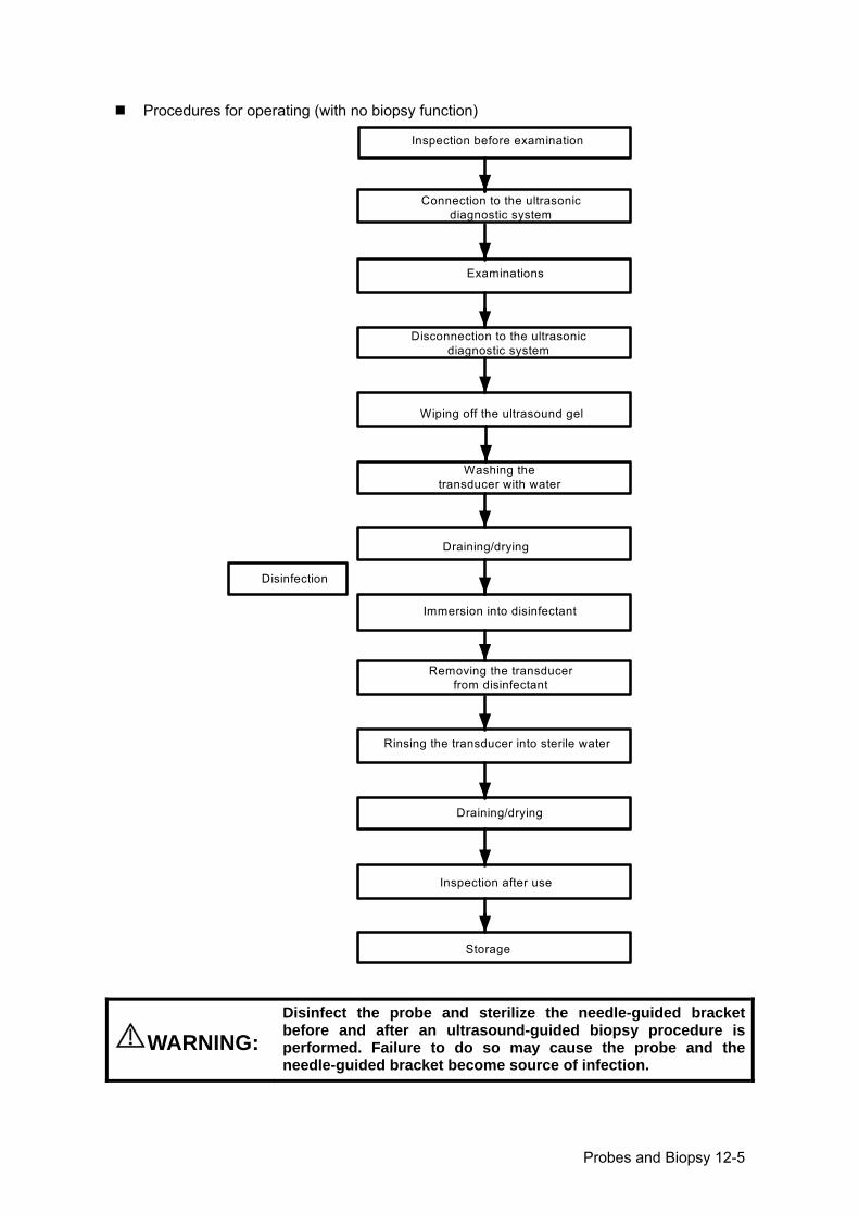
Probes and Biopsy 12-5
Procedures for operating (with no biopsy function)
Inspection before examination
Connection to the ultrasonic diagnostic system
Examinations
Wiping off the ultrasound gel
Washing the transducer with water
Draining/drying
Immersion into disinfectant
Removing the transducer from disinfectant
Rinsing the transducer into sterile water
Draining/drying
Inspection after use
Storage
Disinfection
Disconnection to the ultrasonic diagnostic system
WARNING: Disinfect the probe and sterilize the needle-guided bracket before and after an ultrasound-guided biopsy procedure is performed. Failure to do so may cause the probe and the needle-guided bracket become source of infection.
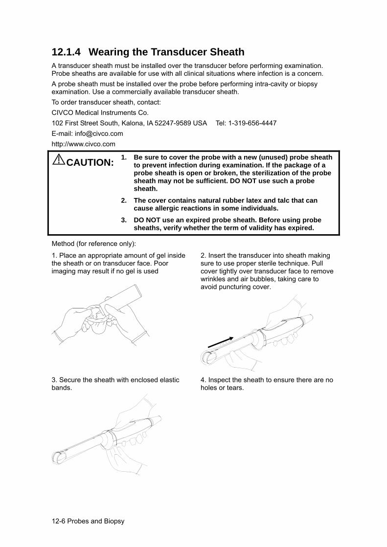
12-6 Probes and Biopsy
12.1.4 Wearing the Transducer Sheath A transducer sheath must be installed over the transducer before performing examination. Probe sheaths are available for use with all clinical situations where infection is a concern. A probe sheath must be installed over the probe before performing intra-cavity or biopsy examination. Use a commercially available transducer sheath. To order transducer sheath, contact: CIVCO Medical Instruments Co. 102 First Street South, Kalona, IA 52247-9589 USA Tel: 1-319-656-4447 E-mail: [email protected] http://www.civco.com
CAUTION:
1. Be sure to cover the probe with a new (unused) probe sheath to prevent infection during examination. If the package of a probe sheath is open or broken, the sterilization of the probe sheath may not be sufficient. DO NOT use such a probe sheath.
2. The cover contains natural rubber latex and talc that can cause allergic reactions in some individuals.
3. DO NOT use an expired probe sheath. Before using probe sheaths, verify whether the term of validity has expired.
Method (for reference only):
1. Place an appropriate amount of gel inside the sheath or on transducer face. Poor imaging may result if no gel is used
2. Insert the transducer into sheath making sure to use proper sterile technique. Pull cover tightly over transducer face to remove wrinkles and air bubbles, taking care to avoid puncturing cover.
3. Secure the sheath with enclosed elastic bands.
4. Inspect the sheath to ensure there are no holes or tears.
Probes and Biopsy 12-7
12.1.5 Probes Cleaning and Disinfection After completing each examination, clean and disinfect (or sterilize) the probes as required. When biopsy procedures have been performed, be sure to sterilize the needle-guided bracket. Fail to do so may result in the probe and the needle-guided bracket to becoming sources of infection. Please follow the instructions in the manual for cleaning.
WARNING:Never immerse the probe connector into liquid such as water or disinfectant. Immersion may cause electrical shock or malfunction.
CAUTION: 1. When performing cleaning and disinfection of the probe to prevent infection, wear sterile gloves.
2. After disinfection, rinse the probe thoroughly with sterile water to remove all chemical residues. Chemical residues on the probe may be harmful to the human body.
3 No cleaning and disinfecting may result in the probe becoming a source of infection.
NOTE: 1. After the examination, wipe off the ultrasound gel thoroughly. Otherwise, the ultrasound gel may solidify and degrade the image quality of the transducer.
2. DO NOT make the probe to become overheated (more than 55°C) during cleaning and disinfections. High temperature may cause the probe to become deformed or damaged.
Cleaning Please refer to the instructions in the manual and follow your hospital policy and procedures for cleaning. 1. Disconnect the probe from the system. 2. Wear sterile gloves to prevent infection. 3. Wash the transducer with clean water or soapy water to remove all the foreign matters, or,
wipe the transducer with a soft ethyl carbamate sponge. Avoid using a brush, because it may damage the transducer.
4. Dry the transducer using a sterile cloth or gauze after rinsing. Do not dry the transducer by heating it.
Disinfecting with Sprays
CAUTION: Use protective eyewear when disinfecting using sprays.
1. Wear sterile gloves to prevent infection. 2. After you have finished cleaning, spray the transducer with a disinfectant. Follow the
disinfectant manufacturer’s recommended contact time and mode. 3. Remove any residue with a water-moistened soft cloth on the transducer. 4. Wipe off water on the transducer using sterile cloth or gauze after washing.
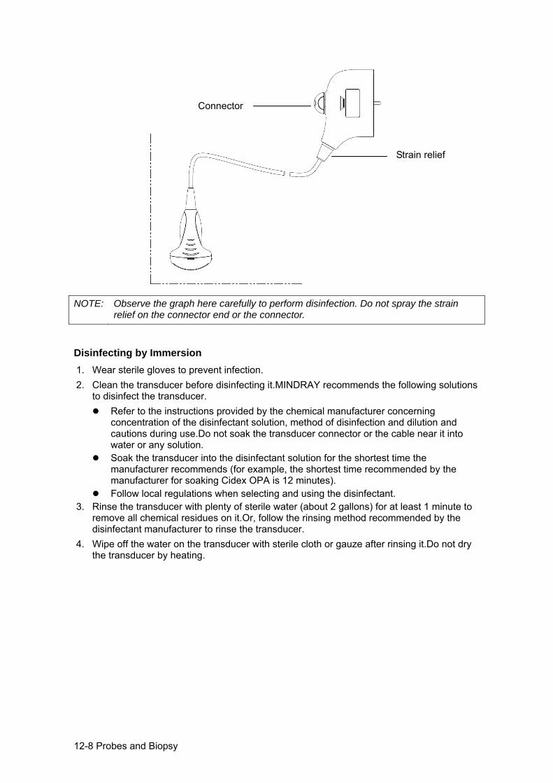
12-8 Probes and Biopsy
NOTE: Observe the graph here carefully to perform disinfection. Do not spray the strain
relief on the connector end or the connector.
Disinfecting by Immersion 1. Wear sterile gloves to prevent infection. 2. Clean the transducer before disinfecting it.MINDRAY recommends the following solutions
to disinfect the transducer. Refer to the instructions provided by the chemical manufacturer concerning
concentration of the disinfectant solution, method of disinfection and dilution and cautions during use.Do not soak the transducer connector or the cable near it into water or any solution.
Soak the transducer into the disinfectant solution for the shortest time the manufacturer recommends (for example, the shortest time recommended by the manufacturer for soaking Cidex OPA is 12 minutes).
Follow local regulations when selecting and using the disinfectant. 3. Rinse the transducer with plenty of sterile water (about 2 gallons) for at least 1 minute to
remove all chemical residues on it.Or, follow the rinsing method recommended by the disinfectant manufacturer to rinse the transducer.
4. Wipe off the water on the transducer with sterile cloth or gauze after rinsing it.Do not dry the transducer by heating.
Connector
Strain relief
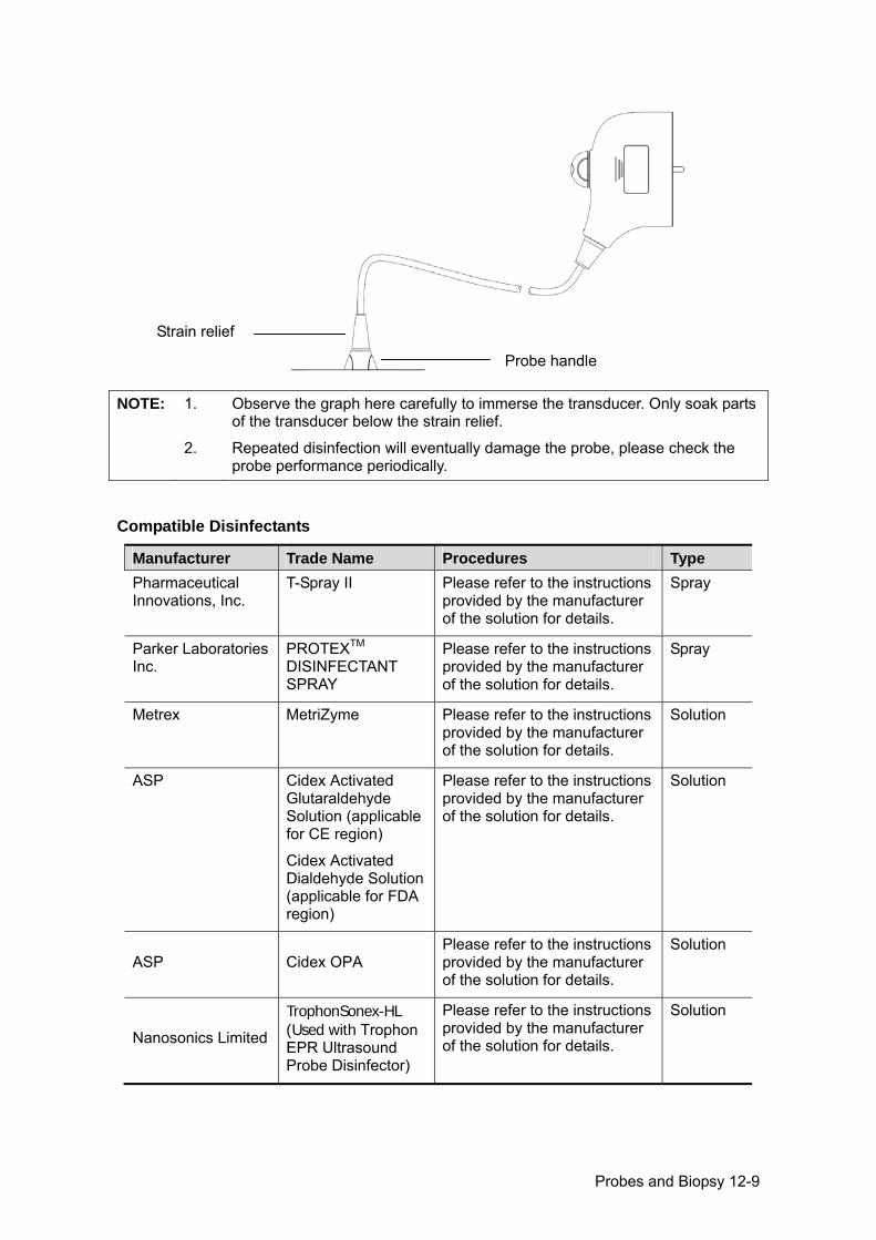
Probes and Biopsy 12-9
NOTE: 1. Observe the graph here carefully to immerse the transducer. Only soak parts
of the transducer below the strain relief.
2. Repeated disinfection will eventually damage the probe, please check the probe performance periodically.
Compatible Disinfectants
Manufacturer Trade Name Procedures Type Pharmaceutical Innovations, Inc.
T-Spray II Please refer to the instructions provided by the manufacturer of the solution for details.
Spray
Parker Laboratories Inc.
PROTEXTM DISINFECTANT SPRAY
Please refer to the instructions provided by the manufacturer of the solution for details.
Spray
Metrex MetriZyme Please refer to the instructions provided by the manufacturer of the solution for details.
Solution
ASP Cidex Activated Glutaraldehyde Solution (applicable for CE region)
Cidex Activated Dialdehyde Solution (applicable for FDA region)
Please refer to the instructions provided by the manufacturer of the solution for details.
Solution
ASP Cidex OPA Please refer to the instructions provided by the manufacturer of the solution for details.
Solution
Nanosonics Limited
TrophonSonex-HL (Used with Trophon EPR Ultrasound Probe Disinfector)
Please refer to the instructions provided by the manufacturer of the solution for details.
Solution
Strain relief
Probe handle
12-10 Probes and Biopsy
Manufacturer Trade Name Procedures Type Ecolab Inc. (not applicable for FDA region)
Ster-Bac Please refer to the instructions provided by the manufacturer of the solution for details.
Solution
Antiseptica (not applicable for FDA region)
Triacid-N Please refer to the instructions provided by the manufacturer of the solution for details.
Solution
Minntech Corporation (not applicable for FDA region)
Minncare® Cold Sterilant
Please refer to the instructions provided by the manufacturer of the solution for details.
Solution
12.1.6 Storage and Transportation When all examinations for the day have been completed, confirm that the transducer is in good condition. After disinfecting the transducer, confirm that the transducer is in good condition and store it in a suitable place so that the next examination can be conducted smoothly. 1. To prevent the transducer from being damaged, do not store it in locations where it may
be exposed to: Direct sunlight or X-rays Sudden changes in temperature Dust Excessive vibration Heat generators
2. Store and transport the transducer under following ambient conditions: Ambient temperature: -20°C ~ 55°C Relative humidity: 30% to 95% (no condensation) Atmospheric pressure: 700 hPa ~ 1060 hPa
3. When the transducer is sent to MINDRAY Customer Service Department or sales representative for repair, be sure to disinfect it and keep it in the carrying case to prevent infection.
4. Disinfect the carrying case as necessary.
12.2 Biopsy Guide
WARNING:
1. The person performing biopsy procedures must understand diagnostic ultrasound thoroughly and have been trained adequately, otherwise, side effects may be caused in the animal.
Probes and Biopsy 12-11
2. In situations listed below, the biopsy needle may fail to penetrate the target. The incorrect biopsy may cause various side effects in the animal.
Use a needle-guided bracket that doesn't match with the transducer.
Mounts the needle-guided bracket incorrectly. Use a biopsy needle that is unsuitable for the
type of biopsy being performed. Use a biopsy needle that is unsuitable for the
type of biopsy being performed.
3. Before and after a biopsy procedure is performed, confirm that the needle-guided bracket is normal. Manually confirm that the parts of the needle-guided bracket do not slip off or move from their proper positions. If the needle-guided bracket is used when parts are not securely and correctly installed, the animal may be injured. If an abnormality is found on the needle-guided bracket, immediately stop using it and contact MINDRAY Customer Service Department or sales representative.
4. Do not use a needle-guided bracket when scanning is
performed. The needle may advance in an incorrect direction and possibly injure the animal. Never perform a biopsy during image scanning.
5. Do not freeze an image while performing biopsy procedure.
6. During biopsy procedures, the needle may deviate from the desired course due to the tissue characteristics or the type of needle. In particular, needles of small diameters may deviate to a greater degree.
7. Sterilize the transducer and the needle-guided bracket before and after each ultrasound-guided biopsy procedure is performed. Fail to do so may cause the transducer and the needle-guided bracket become sources of infection.
8. The needle mark displayed on the ultrasound image does not indicate the actual position of the biopsy needle. Therefore, it should only be used as a reference. Always monitor the relative positions of the biopsy needle during the procedures.
9. Adjust the needle mark before the biopsy procedure is performed.
10. When performing biopsy procedures, use only sterile
ultrasound gel that is certified to be safe. And manage the ultrasound gel properly to ensure that it does not become a source of infection.
11. When performing the operation concerning biopsy, wear sterile gloves.
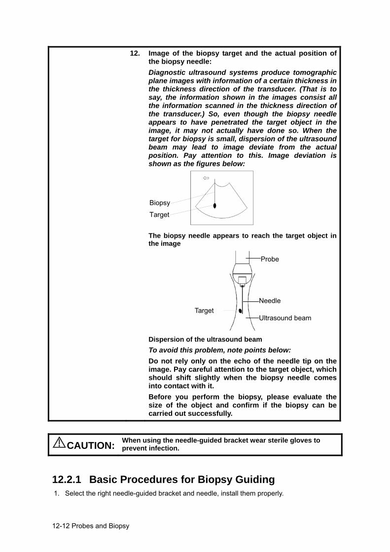
12-12 Probes and Biopsy
12. Image of the biopsy target and the actual position of the biopsy needle: Diagnostic ultrasound systems produce tomographic plane images with information of a certain thickness in the thickness direction of the transducer. (That is to say, the information shown in the images consist all the information scanned in the thickness direction of the transducer.) So, even though the biopsy needle appears to have penetrated the target object in the image, it may not actually have done so. When the target for biopsy is small, dispersion of the ultrasound beam may lead to image deviate from the actual position. Pay attention to this. Image deviation is shown as the figures below:
The biopsy needle appears to reach the target object in the image
Dispersion of the ultrasound beam To avoid this problem, note points below: Do not rely only on the echo of the needle tip on the image. Pay careful attention to the target object, which should shift slightly when the biopsy needle comes into contact with it. Before you perform the biopsy, please evaluate the size of the object and confirm if the biopsy can be carried out successfully.
CAUTION: When using the needle-guided bracket wear sterile gloves to prevent infection.
12.2.1 Basic Procedures for Biopsy Guiding 1. Select the right needle-guided bracket and needle, install them properly.
Target
Biopsy
Probe
Needle
Ultrasound beam Target
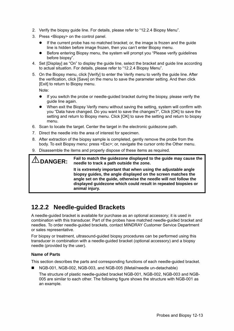
Probes and Biopsy 12-13
2. Verify the biopsy guide line. For details, please refer to “12.2.4 Biopsy Menu”. 3. Press <Biopsy> on the control panel.
If the current probe has no matched bracket; or, the image is frozen and the guide line is hidden before image frozen, then you can’t enter Biopsy menu.
Before entering Biopsy menu, the system will prompt you “Please verify guidelines before biopsy”.
4. Set [Display] as “On” to display the guide line, select the bracket and guide line according to actual situation. For details, please refer to “12.2.4 Biopsy Menu”.
5. On the Biopsy menu, click [Verify] to enter the Verify menu to verify the guide line. After the verification, click [Save] on the menu to save the parameter setting. And then click [Exit] to return to Biopsy menu. Note:
If you switch the probe or needle-guided bracket during the biopsy, please verify the guide line again.
When exit the Biopsy Verify menu without saving the setting, system will confirm with you “Data have changed. Do you want to save the changes?”, Click [OK] to save the setting and return to Biopsy menu. Click [OK] to save the setting and return to biopsy menu.
6. Scan to locate the target. Center the target in the electronic guidezone path. 7. Direct the needle into the area of interest for specimen. 8. After extraction of the biopsy sample is completed, gently remove the probe from the
body. To exit Biopsy menu: press <Esc>; or, navigate the cursor onto the Other menu. 9. Disassemble the items and properly dispose of these items as required.
DANGER: Fail to match the guidezone displayed to the guide may cause the needle to track a path outside the zone. It is extremely important that when using the adjustable angle biopsy guides, the angle displayed on the screen matches the angle set on the guide, otherwise the needle will not follow the displayed guidezone which could result in repeated biopsies or animal injury.
12.2.2 Needle-guided Brackets A needle-guided bracket is available for purchase as an optional accessory; it is used in combination with this transducer. Part of the probes have matched needle-guided bracket and needles. To order needle-guided brackets, contact MINDRAY Customer Service Department or sales representative. For biopsy or treatment, ultrasound-guided biopsy procedures can be performed using this transducer in combination with a needle-guided bracket (optional accessory) and a biopsy needle (provided by the user).
Name of Parts This section describes the parts and corresponding functions of each needle-guided bracket.
NGB-001, NGB-002, NGB-003, and NGB-005 (Metal/needle un-detachable) The structure of plastic needle-guided bracket NGB-001, NGB-002, NGB-003 and NGB-005 are similar to each other. The following figure shows the structure with NGB-001 as an example.
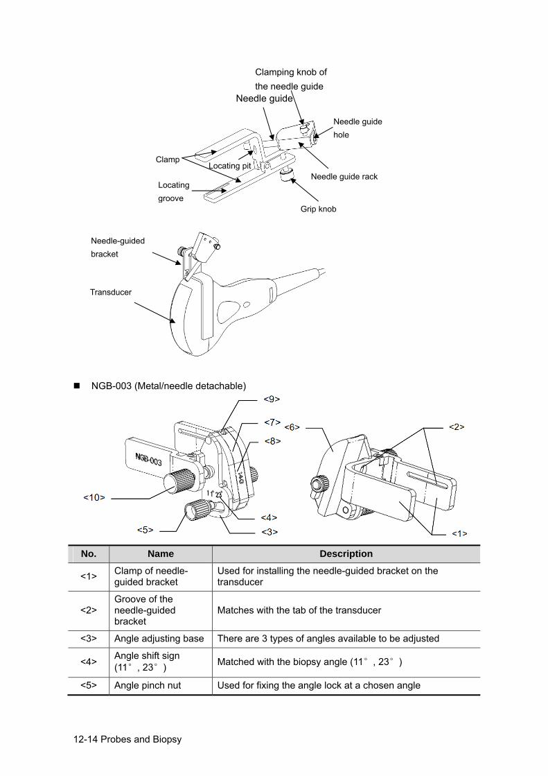
12-14 Probes and Biopsy
NGB-003 (Metal/needle detachable)
No. Name Description
<1> Clamp of needle-guided bracket
Used for installing the needle-guided bracket on the transducer
<2> Groove of the needle-guided bracket
Matches with the tab of the transducer
<3> Angle adjusting base There are 3 types of angles available to be adjusted
<4> Angle shift sign (11°, 23°) Matched with the biopsy angle (11°, 23°)
<5> Angle pinch nut Used for fixing the angle lock at a chosen angle
Needle guide rackLocating groove
Clamp
Needle guide
Clamping knob of the needle guide
Needle guide hole
Grip knob
Locating pit
Transducer
Needle-guided bracket
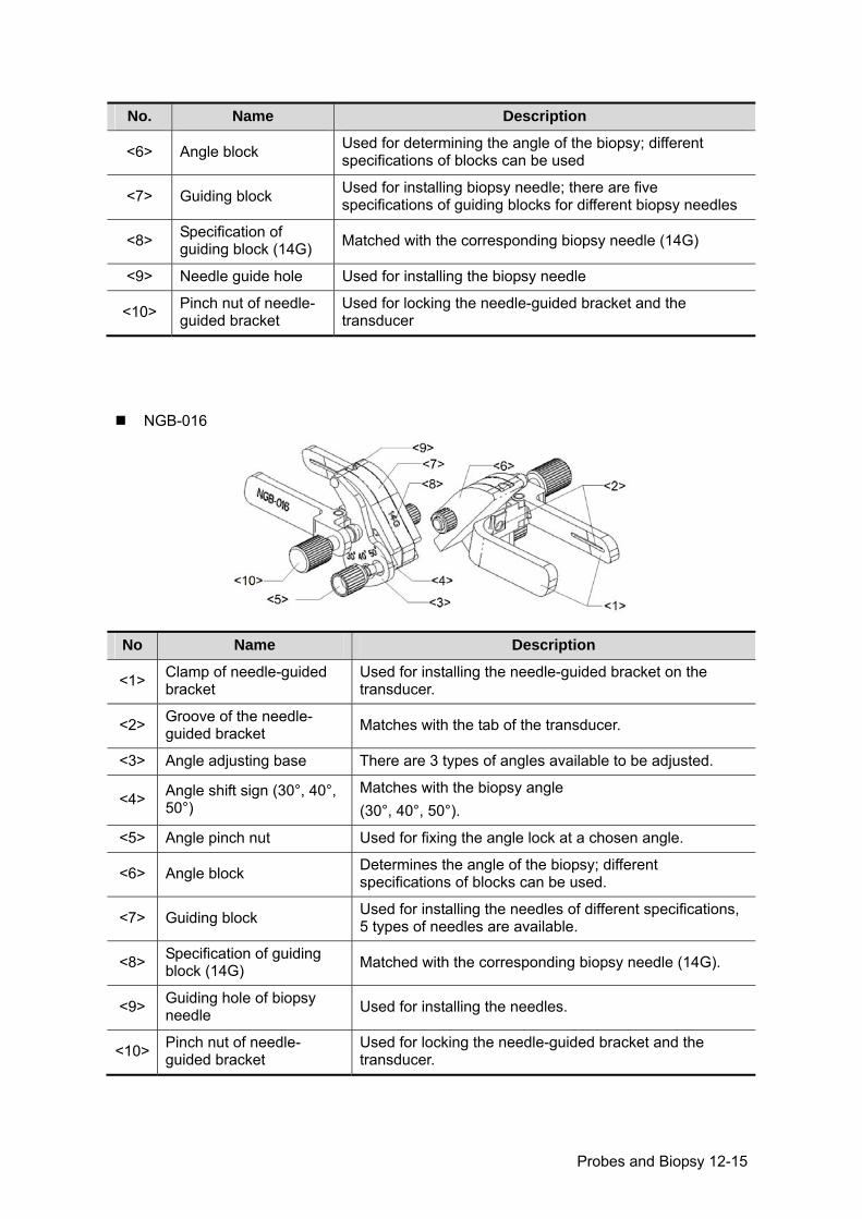
Probes and Biopsy 12-15
No. Name Description
<6> Angle block Used for determining the angle of the biopsy; different specifications of blocks can be used
<7> Guiding block Used for installing biopsy needle; there are five specifications of guiding blocks for different biopsy needles
<8> Specification of guiding block (14G) Matched with the corresponding biopsy needle (14G)
<9> Needle guide hole Used for installing the biopsy needle
<10> Pinch nut of needle-guided bracket
Used for locking the needle-guided bracket and the transducer
NGB-016
No Name Description
<1> Clamp of needle-guided bracket
Used for installing the needle-guided bracket on the transducer.
<2> Groove of the needle-guided bracket Matches with the tab of the transducer.
<3> Angle adjusting base There are 3 types of angles available to be adjusted.
<4> Angle shift sign (30°, 40°, 50°)
Matches with the biopsy angle (30°, 40°, 50°).
<5> Angle pinch nut Used for fixing the angle lock at a chosen angle.
<6> Angle block Determines the angle of the biopsy; different specifications of blocks can be used.
<7> Guiding block Used for installing the needles of different specifications, 5 types of needles are available.
<8> Specification of guiding block (14G) Matched with the corresponding biopsy needle (14G).
<9> Guiding hole of biopsy needle Used for installing the needles.
<10> Pinch nut of needle-guided bracket
Used for locking the needle-guided bracket and the transducer.
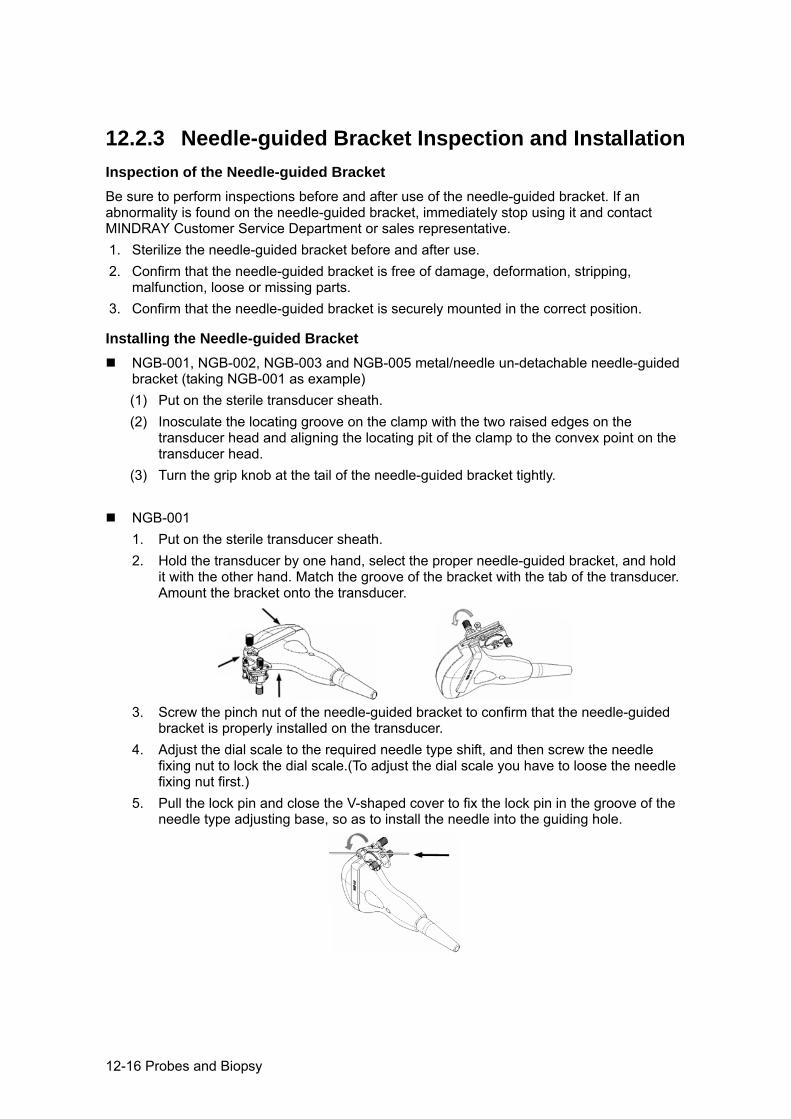
12-16 Probes and Biopsy
12.2.3 Needle-guided Bracket Inspection and Installation Inspection of the Needle-guided Bracket Be sure to perform inspections before and after use of the needle-guided bracket. If an abnormality is found on the needle-guided bracket, immediately stop using it and contact MINDRAY Customer Service Department or sales representative. 1. Sterilize the needle-guided bracket before and after use. 2. Confirm that the needle-guided bracket is free of damage, deformation, stripping,
malfunction, loose or missing parts. 3. Confirm that the needle-guided bracket is securely mounted in the correct position.
Installing the Needle-guided Bracket NGB-001, NGB-002, NGB-003 and NGB-005 metal/needle un-detachable needle-guided
bracket (taking NGB-001 as example) (1) Put on the sterile transducer sheath. (2) Inosculate the locating groove on the clamp with the two raised edges on the
transducer head and aligning the locating pit of the clamp to the convex point on the transducer head.
(3) Turn the grip knob at the tail of the needle-guided bracket tightly.
NGB-001 1. Put on the sterile transducer sheath. 2. Hold the transducer by one hand, select the proper needle-guided bracket, and hold
it with the other hand. Match the groove of the bracket with the tab of the transducer. Amount the bracket onto the transducer.
3. Screw the pinch nut of the needle-guided bracket to confirm that the needle-guided bracket is properly installed on the transducer.
4. Adjust the dial scale to the required needle type shift, and then screw the needle fixing nut to lock the dial scale.(To adjust the dial scale you have to loose the needle fixing nut first.)
5. Pull the lock pin and close the V-shaped cover to fix the lock pin in the groove of the needle type adjusting base, so as to install the needle into the guiding hole.
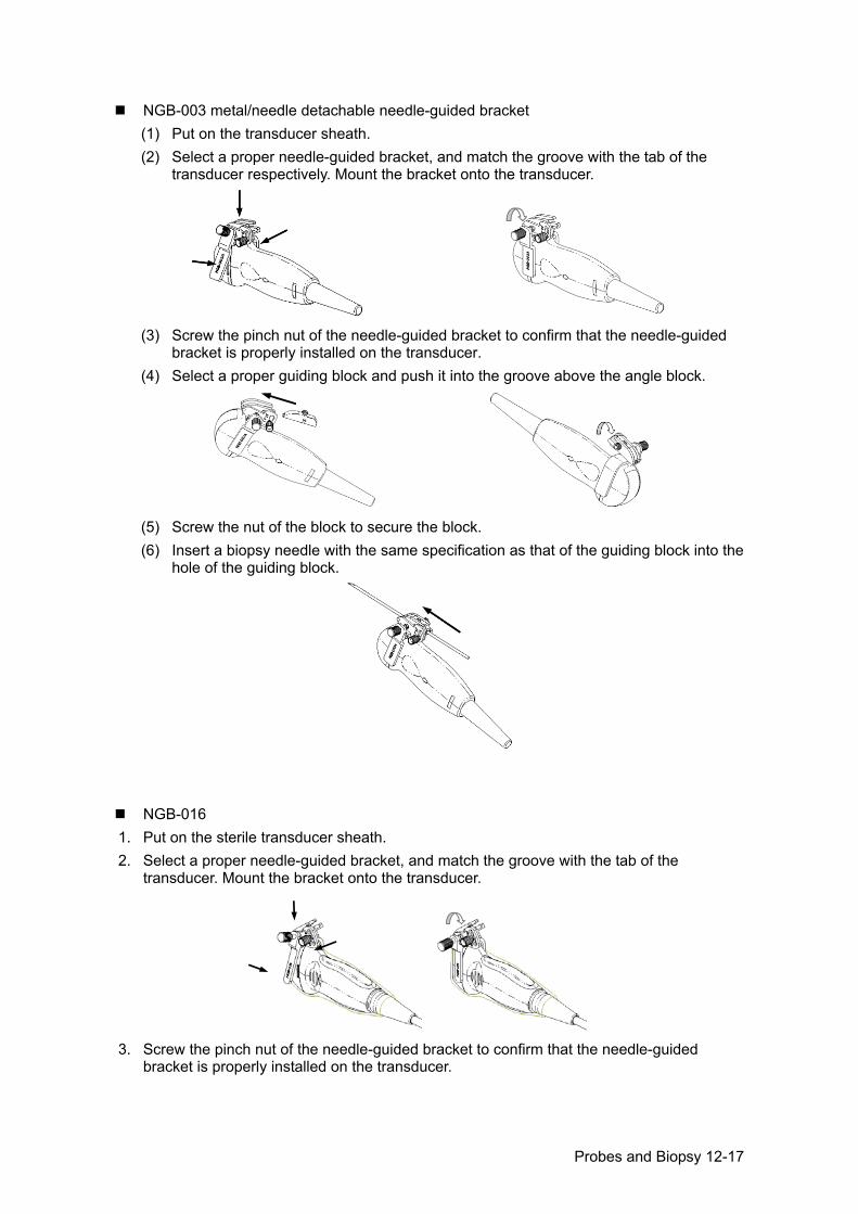
Probes and Biopsy 12-17
NGB-003 metal/needle detachable needle-guided bracket (1) Put on the transducer sheath. (2) Select a proper needle-guided bracket, and match the groove with the tab of the
transducer respectively. Mount the bracket onto the transducer.
(3) Screw the pinch nut of the needle-guided bracket to confirm that the needle-guided
bracket is properly installed on the transducer. (4) Select a proper guiding block and push it into the groove above the angle block.
(5) Screw the nut of the block to secure the block. (6) Insert a biopsy needle with the same specification as that of the guiding block into the
hole of the guiding block.
NGB-016 1. Put on the sterile transducer sheath. 2. Select a proper needle-guided bracket, and match the groove with the tab of the
transducer. Mount the bracket onto the transducer.
3. Screw the pinch nut of the needle-guided bracket to confirm that the needle-guided
bracket is properly installed on the transducer.
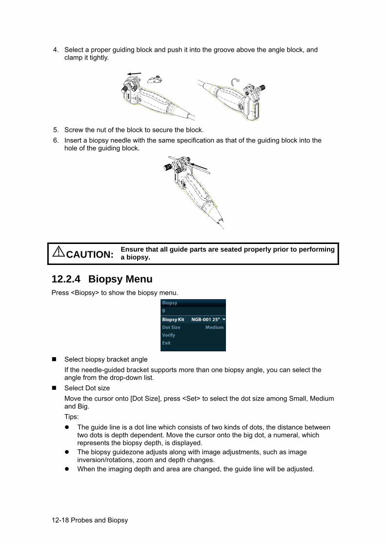
12-18 Probes and Biopsy
4. Select a proper guiding block and push it into the groove above the angle block, and clamp it tightly.
5. Screw the nut of the block to secure the block. 6. Insert a biopsy needle with the same specification as that of the guiding block into the
hole of the guiding block.
CAUTION: Ensure that all guide parts are seated properly prior to performing a biopsy.
12.2.4 Biopsy Menu Press <Biopsy> to show the biopsy menu.
Select biopsy bracket angle
If the needle-guided bracket supports more than one biopsy angle, you can select the angle from the drop-down list.
Select Dot size Move the cursor onto [Dot Size], press <Set> to select the dot size among Small, Medium and Big. Tips:
The guide line is a dot line which consists of two kinds of dots, the distance between two dots is depth dependent. Move the cursor onto the big dot, a numeral, which represents the biopsy depth, is displayed.
The biopsy guidezone adjusts along with image adjustments, such as image inversion/rotations, zoom and depth changes.
When the imaging depth and area are changed, the guide line will be adjusted.
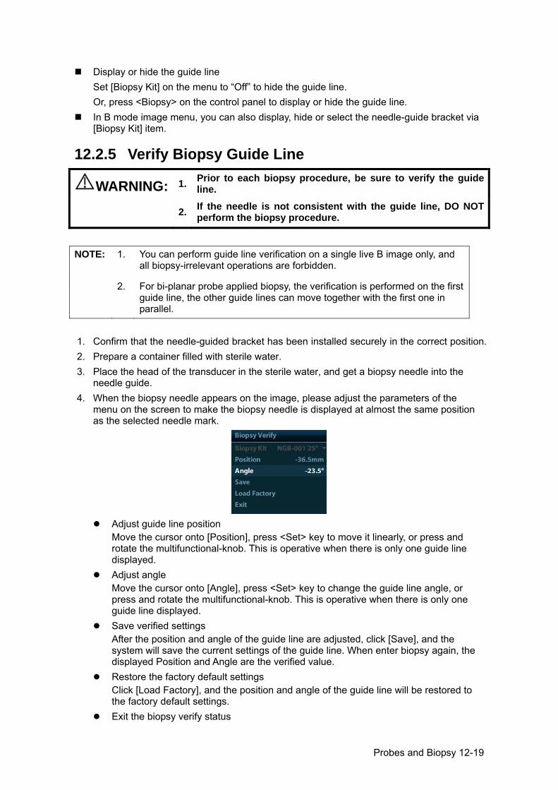
Probes and Biopsy 12-19
Display or hide the guide line Set [Biopsy Kit] on the menu to “Off” to hide the guide line. Or, press <Biopsy> on the control panel to display or hide the guide line.
In B mode image menu, you can also display, hide or select the needle-guide bracket via [Biopsy Kit] item.
12.2.5 Verify Biopsy Guide Line
WARNING: 1. Prior to each biopsy procedure, be sure to verify the guide line.
2. If the needle is not consistent with the guide line, DO NOT perform the biopsy procedure.
NOTE:
1. You can perform guide line verification on a single live B image only, and all biopsy-irrelevant operations are forbidden.
2. For bi-planar probe applied biopsy, the verification is performed on the first guide line, the other guide lines can move together with the first one in parallel.
1. Confirm that the needle-guided bracket has been installed securely in the correct position. 2. Prepare a container filled with sterile water. 3. Place the head of the transducer in the sterile water, and get a biopsy needle into the
needle guide. 4. When the biopsy needle appears on the image, please adjust the parameters of the
menu on the screen to make the biopsy needle is displayed at almost the same position as the selected needle mark.
Adjust guide line position
Move the cursor onto [Position], press <Set> key to move it linearly, or press and rotate the multifunctional-knob. This is operative when there is only one guide line displayed.
Adjust angle Move the cursor onto [Angle], press <Set> key to change the guide line angle, or press and rotate the multifunctional-knob. This is operative when there is only one guide line displayed.
Save verified settings After the position and angle of the guide line are adjusted, click [Save], and the system will save the current settings of the guide line. When enter biopsy again, the displayed Position and Angle are the verified value.
Restore the factory default settings Click [Load Factory], and the position and angle of the guide line will be restored to the factory default settings.
Exit the biopsy verify status
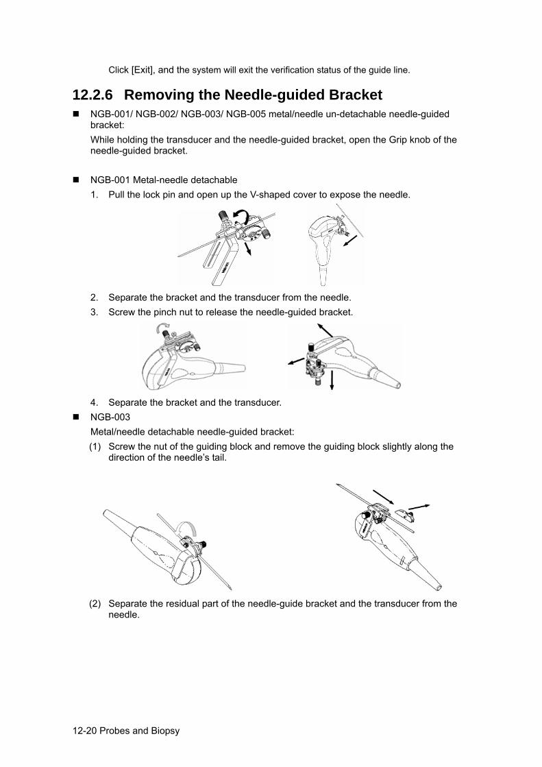
12-20 Probes and Biopsy
Click [Exit], and the system will exit the verification status of the guide line.
12.2.6 Removing the Needle-guided Bracket NGB-001/ NGB-002/ NGB-003/ NGB-005 metal/needle un-detachable needle-guided
bracket: While holding the transducer and the needle-guided bracket, open the Grip knob of the needle-guided bracket.
NGB-001 Metal-needle detachable
1. Pull the lock pin and open up the V-shaped cover to expose the needle.
2. Separate the bracket and the transducer from the needle. 3. Screw the pinch nut to release the needle-guided bracket.
4. Separate the bracket and the transducer.
NGB-003 Metal/needle detachable needle-guided bracket: (1) Screw the nut of the guiding block and remove the guiding block slightly along the
direction of the needle’s tail.
(2) Separate the residual part of the needle-guide bracket and the transducer from the
needle.
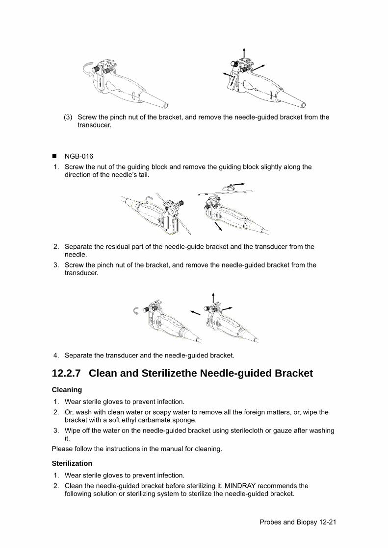
Probes and Biopsy 12-21
(3) Screw the pinch nut of the bracket, and remove the needle-guided bracket from the
transducer.
NGB-016 1. Screw the nut of the guiding block and remove the guiding block slightly along the
direction of the needle’s tail.
2. Separate the residual part of the needle-guide bracket and the transducer from the
needle. 3. Screw the pinch nut of the bracket, and remove the needle-guided bracket from the
transducer.
4. Separate the transducer and the needle-guided bracket.
12.2.7 Clean and Sterilizethe Needle-guided Bracket Cleaning 1. Wear sterile gloves to prevent infection. 2. Or, wash with clean water or soapy water to remove all the foreign matters, or, wipe the
bracket with a soft ethyl carbamate sponge. 3. Wipe off the water on the needle-guided bracket using sterilecloth or gauze after washing
it. Please follow the instructions in the manual for cleaning.
Sterilization 1. Wear sterile gloves to prevent infection. 2. Clean the needle-guided bracket before sterilizing it. MINDRAY recommends the
following solution or sterilizing system to sterilize the needle-guided bracket.
12-22 Probes and Biopsy
3. Follow local regulations when selecting and using the disinfectant. Glutaraldehyde-based sterilant:
Chemical name Trade name Procedures
Glutaraldehyde (2.2-2.7%)
Cidex Activated Glutaraldehyde Solution (applicable for CE region)
Please refer to the instructions provided by the manufacturer of the solution for details. Soak the transducer into the activated solution for 10 hours (20-25)
Glutaraldehyde (2.4%)
Cidex Activated Dialdehyde Solution (applicable for FDA region)
Hydrogen Peroxide and Peroxyacetic Acid -based disinfectant:
Trade Name Chemical Name Procedures
Minncare® Cold Sterilant
22% Hydrogen Peroxide 4.5% Peroxyacetic Acid
Dilute the sterilant with dsterilized purified water (1:20). Immersed time: 11 hours. Temperature: 20-25. Please refer to the instructions provided by the manufacturer of the solution for details.
Refer to the instructions provided by the chemical manufacturer concerning
concentration of the solution, and method of disinfections and dilution. Note that the glutaraldehyde disinfectant solution needs an activating solution.
Rinse the needle-guided bracket thoroughly with sterile water to remove all chemical residues on it.
Wipe off the water on the needle-guided bracket with sterile cloth or gauze after rinsing it.
STERRAD 100S low-temperature hydrogen peroxide gas plasma sterilization system
Chemical name Trade name Procedures
Hydrogen peroxide gas plasma
Hydrogen peroxide vapor
Please refer to the instructions provided by the producer of the solution for details.
Refer to the instruction of STERRAD 100S sterilizing system provided by the manufacturer for operation instructions and cautions.
The STERRAD 100S low-temperature hydrogen peroxide gas plasma sterilization system is available for metal needle-guided brackets.
High-pressure steam sterilization (only applicable for metal guided-bracket) Autoclaving (moist heat) 121° C for 20 minutes.
NOTE: The high-pressure steam/ immersion sterilization do not affect the bracket duration life, and the duration life is affected by the daily application of the bracket. Please check the appearance of the bracket before using.
12.2.8 Storage and Transportation Don’t use the carrying case for storing the needle-guided bracket. If the carrying case is
used for storage, it may become a source of infection.
Probes and Biopsy 12-23
Between examinations, keep the needle-guided bracket in a sterile environment. When the needle-guided bracket is sent to your MINDRAY representative for repair, be
sure to disinfect or sterilize it and keep it in the carrying case to prevent infection. Sterilize the carrying case as necessary. Store or transport the needle-guided bracket under the following ambient conditions:
Ambient temperature: -20°C ~ 55°C Relative humidity: 30% to 95% (no condensation)
12.2.9 Disposal Be sure to dispose the needle-guided bracket only after sterilizing it. Contact your MINDRAY representative when disposing of this device.
12.3 Lithotrity “Lithotrity” helps to locate the focus point of lithotrity wave during lithotrity treatment. By watching the procedure of lithotrity in real-time and adjusting the intension and frequency of the lithotrity wave, the harm to the animals can be reduced to the least.
To enter lithotrity mode: Click [Lithotrity] in the image menuto turn on the lithotrity. In lithotrity mode:
The lithotrity line is a vertical dotted line located in the middle of the screen, the position and direction of which cannot be changed.
The lithotrity mark is a “×” mark located on the lithotrity line which can be moved up and down along the lithotrity line by rolling the track ball.
The depth of the mark is displayed in the image parameter area of the screen.

Battery 13-1
13 Battery
WARNING: 1. DO NOT install or detach the battery ad arbitrium The batteries have protective mechanism and circuit. DO NOT disassemble or alter the battery.
2. DO NOT short-circuit the batteries by directly connecting the negative terminals with metal objects.
3. DO NOT heat the battery or discard it in a fire. 4. Keep the batteries away from fire and other heat
sources. 5. DO NOT immerse the batteries in water or allow them
to get wet. 6. DO NOT charge the batteries near a heat source or in
direct sunlight. 7. DO NOT pierce the batteries with a sharp object, hit or
step on them. 8. DO NOT use the batteries mixed with other battery
models. 9. DO NOT put the batteries into a microwave oven or
pressurized container. 10. If the batteries emit an odor or heat, are deformed or
discolored, or in a way appear abnormal during use, charging or storage, immediately remove them and stop using them.
13.1 Overview The battery charges when the system is connected to the AC power supply.
Generally, if the system is turned off, a completely discharged battery will fully charge in less than 3 hours.
NOTE: 1. It is recommended to charge the batteries when the system is turned off, thus you can quickly charge the battery and save time.
2. Power off the system if you will not use the system for a long period of time (including storage/ transportation condition), and you should not allow the system in standby status, otherwise the batteries will be out of power and permanently damaged.
When the external power supply is not connected, a lithium-ion battery will provide the power. The model of the chargeable lithium-ion battery (hereinafter called battery for short) is LI34I002A.
NOTE: Only use the specified batteries.

13-2 Battery
13.2 Precautions 1. Before using the battery, carefully read the description in the label on the surface of the
battery. 2. When you use the battery at the first time and find that it is dirty or emit an odor, do not
use it. 3. Do not expose the battery to heat sources or high pressure. 4. Do not leave the battery in direct sunlight. 5. Store the battery out of the reach of children. Store the battery out of the reach of children. 6. The battery is designed to be charged only in this system; charge the battery only when
the ambient temperature is between 0 and 40 . 7. When the battery is out of power, please charge it immediately. 8. When the battery will not be used for 10 days or over, take it out of the system and store it
with caution. DO NOT wrap it with conductive material; store it in shady, cool and dry place.
9. Do not knock the battery.
13.3 Installing and Removing the Batteries
WARNING: Turn off the system and disconnect the adapter from the main unit before installing or removing batteries. DO NOT install or remove batteries when the system is turned on or the system is turned off but the adapter is connected with the system.
The battery is put in the battery bays at the back side of the system. You can install or remove it when the system is turned off and the power cord is disconnected from the main unit. To install the battery: 1. Turn off the unit and detach the power cord from the main unit. 2. You can see a battery bay at the back of the system. (Note that the battery shall be put in
correct direction). Put the battery into the bay and push to the right side until it’s tightly locked.
3. Close the battery cover.
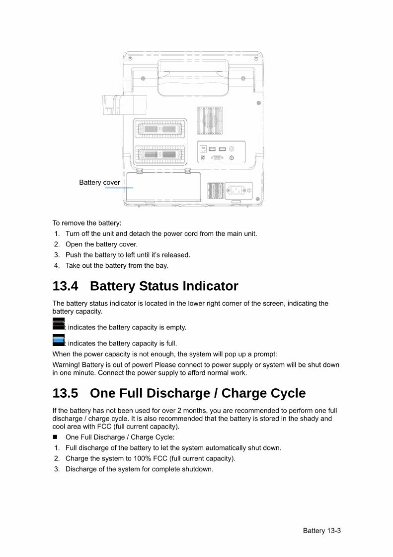
Battery 13-3
To remove the battery: 1. Turn off the unit and detach the power cord from the main unit. 2. Open the battery cover. 3. Push the battery to left until it’s released. 4. Take out the battery from the bay.
13.4 Battery Status Indicator The battery status indicator is located in the lower right corner of the screen, indicating the battery capacity.
: indicates the battery capacity is empty.
: indicates the battery capacity is full. When the power capacity is not enough, the system will pop up a prompt: Warning! Battery is out of power! Please connect to power supply or system will be shut down in one minute. Connect the power supply to afford normal work.
13.5 One Full Discharge / Charge Cycle If the battery has not been used for over 2 months, you are recommended to perform one full discharge / charge cycle. It is also recommended that the battery is stored in the shady and cool area with FCC (full current capacity).
One Full Discharge / Charge Cycle: 1. Full discharge of the battery to let the system automatically shut down. 2. Charge the system to 100% FCC (full current capacity). 3. Discharge of the system for complete shutdown.
Battery cover
13-4 Battery
13.6 Checking Battery Performance The battery performance may be degraded over time, so you need to check the battery performance periodically. The checking procedures are shown as follows: 1. Stop the ultrasound exam. 2. Connect the system to the AC power supply to charge the batteries until current capacity
is full. 3. Disconnect the system from the AC power supply to power the system by the batteries
until the system automatically shuts down. 4. The powering time of the batteries indicates the battery performance. If the powering time of the battery is much shorter than that specified in the Specification Manual, you may replace the battery or contact the service personnel.
13.7 Battery Disposal You need to dispose of the battery when it is damages, severely degraded or used for 3 years.
NOTE: You should observe the local regulations when disposing of the battery.
Acoustic Output 14-1
14 Acoustic Output
This section of the operator’s manual applies to the overall system including the main unit, probes, accessories and peripherals. This section contains important safety information for operators of the device, pertaining to acoustic output and how to control animal exposure through use of the ALARA (as low as reasonably achievable) principle. Also this section contains information regarding the acoustic output testing and the real-time output display. Read this information carefully before using the system.
14.1 Concerns with Bioeffects Diagnostic ultrasound is recognized as being safe. In fact, there have been no reports of injuries to animals caused by diagnostic ultrasound. It cannot be stated categorically that ultrasound is 100% safe. Studies have revealed that ultrasound with extremely high intensity is harmful to body tissues. Diagnostic ultrasound technology has made a great leap forward during the last several years. This rapid advance has generated concerns about the potential risk of bioeffects when new applications or diagnostic technologies become available.
14.2 Prudent Use Statement Although there are no confirmed biological effects on animals caused by exposures from present diagnostic ultrasound instruments, the possibility exists that such biological effects may be identified in the future. Thus ultrasound should be used in a prudent manner to provide medical benefit to the animal. High exposure levels and long exposure times should be avoided while acquiring necessary clinical information.
14.3 ALARA Principle (As Low As Reasonably Achievable)
It is required to practice ALARA when using ultrasound energy. Practicing ALARA ensures that the total energy level is controlled below a low enough level at which bioeffects are not generated while diagnostic information is being accumulated. The total energy is controlled by output intensity and total radiation time. The output intensity necessary for examinations differs depending on the animal and the clinical case. Not all examinations can be performed with an extremely low level of acoustic energy. Controlling the acoustic level at an extremely low level leads to low-quality images or insufficient Doppler signals, adversely affecting the reliability of the diagnosis. However, increasing the acoustic power more than necessary does not always contribute to an increase in quality of information required for diagnosis, rather increasing the risk of generating bioeffects. Users must take responsibility for the safety of animals and utilize ultrasound deliberately. Deliberate use of ultrasound means that output power of ultrasound must be selected based on ALARA. Additional information regarding the concept of ALARA and the possible bioeffects of Ultrasound is available in a document from the AIUM (American Institute of Ultrasound Medicine) title “Medical Ultrasound Safety”.
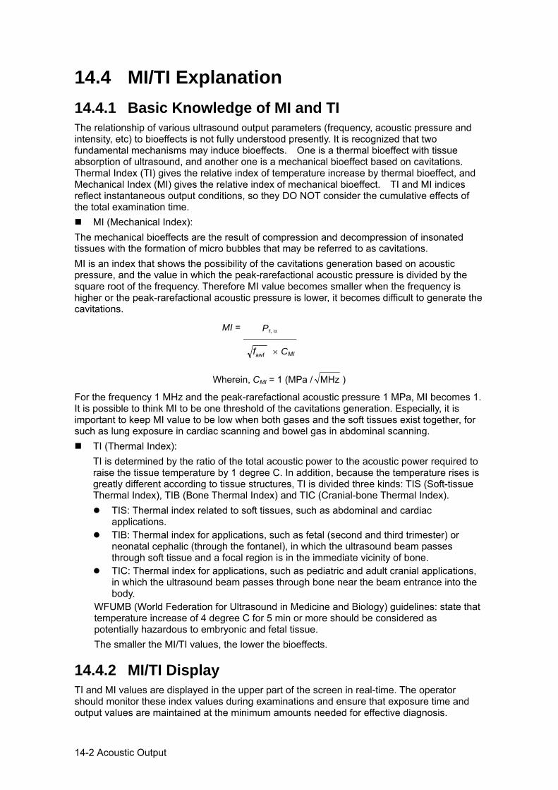
14-2 Acoustic Output
14.4 MI/TI Explanation 14.4.1 Basic Knowledge of MI and TI The relationship of various ultrasound output parameters (frequency, acoustic pressure and intensity, etc) to bioeffects is not fully understood presently. It is recognized that two fundamental mechanisms may induce bioeffects. One is a thermal bioeffect with tissue absorption of ultrasound, and another one is a mechanical bioeffect based on cavitations. Thermal Index (TI) gives the relative index of temperature increase by thermal bioeffect, and Mechanical Index (MI) gives the relative index of mechanical bioeffect. TI and MI indices reflect instantaneous output conditions, so they DO NOT consider the cumulative effects of the total examination time.
MI (Mechanical Index): The mechanical bioeffects are the result of compression and decompression of insonated tissues with the formation of micro bubbles that may be referred to as cavitations. MI is an index that shows the possibility of the cavitations generation based on acoustic pressure, and the value in which the peak-rarefactional acoustic pressure is divided by the square root of the frequency. Therefore MI value becomes smaller when the frequency is higher or the peak-rarefactional acoustic pressure is lower, it becomes difficult to generate the cavitations.
MI = Pr, α
awff × CMI
Wherein, CMI = 1 (MPa / MHz )
For the frequency 1 MHz and the peak-rarefactional acoustic pressure 1 MPa, MI becomes 1. It is possible to think MI to be one threshold of the cavitations generation. Especially, it is important to keep MI value to be low when both gases and the soft tissues exist together, for such as lung exposure in cardiac scanning and bowel gas in abdominal scanning.
TI (Thermal Index): TI is determined by the ratio of the total acoustic power to the acoustic power required to raise the tissue temperature by 1 degree C. In addition, because the temperature rises is greatly different according to tissue structures, TI is divided three kinds: TIS (Soft-tissue Thermal Index), TIB (Bone Thermal Index) and TIC (Cranial-bone Thermal Index).
TIS: Thermal index related to soft tissues, such as abdominal and cardiac applications.
TIB: Thermal index for applications, such as fetal (second and third trimester) or neonatal cephalic (through the fontanel), in which the ultrasound beam passes through soft tissue and a focal region is in the immediate vicinity of bone.
TIC: Thermal index for applications, such as pediatric and adult cranial applications, in which the ultrasound beam passes through bone near the beam entrance into the body.
WFUMB (World Federation for Ultrasound in Medicine and Biology) guidelines: state that temperature increase of 4 degree C for 5 min or more should be considered as potentially hazardous to embryonic and fetal tissue. The smaller the MI/TI values, the lower the bioeffects.
14.4.2 MI/TI Display TI and MI values are displayed in the upper part of the screen in real-time. The operator should monitor these index values during examinations and ensure that exposure time and output values are maintained at the minimum amounts needed for effective diagnosis.
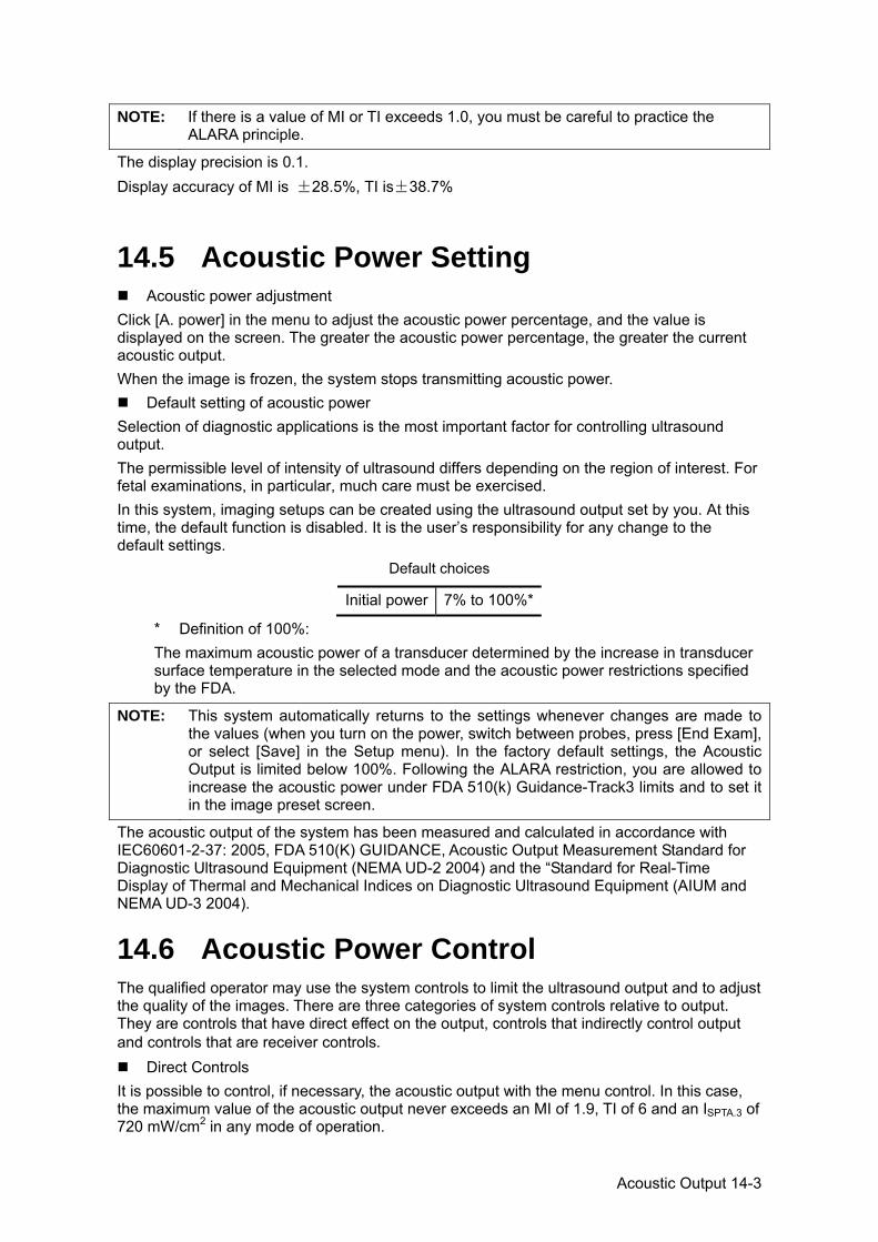
Acoustic Output 14-3
NOTE: If there is a value of MI or TI exceeds 1.0, you must be careful to practice the ALARA principle.
The display precision is 0.1. Display accuracy of MI is ±28.5%, TI is±38.7%
14.5 Acoustic Power Setting Acoustic power adjustment
Click [A. power] in the menu to adjust the acoustic power percentage, and the value is displayed on the screen. The greater the acoustic power percentage, the greater the current acoustic output. When the image is frozen, the system stops transmitting acoustic power.
Default setting of acoustic power Selection of diagnostic applications is the most important factor for controlling ultrasound output. The permissible level of intensity of ultrasound differs depending on the region of interest. For fetal examinations, in particular, much care must be exercised. In this system, imaging setups can be created using the ultrasound output set by you. At this time, the default function is disabled. It is the user’s responsibility for any change to the default settings.
Default choices
Initial power 7% to 100%*
* Definition of 100%: The maximum acoustic power of a transducer determined by the increase in transducer surface temperature in the selected mode and the acoustic power restrictions specified by the FDA.
NOTE: This system automatically returns to the settings whenever changes are made to the values (when you turn on the power, switch between probes, press [End Exam], or select [Save] in the Setup menu). In the factory default settings, the Acoustic Output is limited below 100%. Following the ALARA restriction, you are allowed to increase the acoustic power under FDA 510(k) Guidance-Track3 limits and to set it in the image preset screen.
The acoustic output of the system has been measured and calculated in accordance with IEC60601-2-37: 2005, FDA 510(K) GUIDANCE, Acoustic Output Measurement Standard for Diagnostic Ultrasound Equipment (NEMA UD-2 2004) and the “Standard for Real-Time Display of Thermal and Mechanical Indices on Diagnostic Ultrasound Equipment (AIUM and NEMA UD-3 2004).
14.6 Acoustic Power Control The qualified operator may use the system controls to limit the ultrasound output and to adjust the quality of the images. There are three categories of system controls relative to output. They are controls that have direct effect on the output, controls that indirectly control output and controls that are receiver controls.
Direct Controls It is possible to control, if necessary, the acoustic output with the menu control. In this case, the maximum value of the acoustic output never exceeds an MI of 1.9, TI of 6 and an ISPTA.3 of 720 mW/cm2 in any mode of operation.
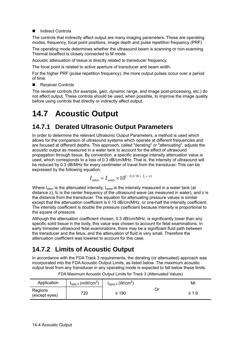
14-4 Acoustic Output
Indirect Controls The controls that indirectly affect output are many imaging parameters. These are operating modes, frequency, focal point positions, image depth and pulse repetition frequency (PRF). The operating mode determines whether the ultrasound beam is scanning or non-scanning. Thermal bioeffect is closely connected to M mode. Acoustic attenuation of tissue is directly related to transducer frequency. The focal point is related to active aperture of transducer and beam width. For the higher PRF (pulse repetition frequency), the more output pulses occur over a period of time.
Receiver Controls The receiver controls (for example, gain, dynamic range, and image post-processing, etc.) do not affect output. These controls should be used, when possible, to improve the image quality before using controls that directly or indirectly affect output.
14.7 Acoustic Output 14.7.1 Derated Ultrasonic Output Parameters In order to determine the relevant Ultrasonic Output Parameters, a method is used which allows for the comparison of ultrasound systems which operate at different frequencies and are focused at different depths. This approach, called "derating" or "attenuating", adjusts the acoustic output as measured in a water tank to account for the effect of ultrasound propagation through tissue. By convention, a specific average intensity attenuation value is used, which corresponds to a loss of 0.3 dB/cm/MHz. That is, the intensity of ultrasound will be reduced by 0.3 dB/MHz for every centimeter of travel from the transducer. This can be expressed by the following equation:
)10/3.0-(10 zfwateratten
cII ×××=
Where Iatten is the attenuated intensity, Iwater is the intensity measured in a water tank (at distance z), fc is the center frequency of the ultrasound wave (as measured in water), and z is the distance from the transducer. The equation for attenuating pressure values is similar except that the attenuation coefficient is 0.15 dB/cm/MHz, or one-half the intensity coefficient. The intensity coefficient is double the pressure coefficient because intensity is proportional to the square of pressure. Although the attenuation coefficient chosen, 0.3 dB/cm/MHz, is significantly lower than any specific solid tissue in the body, this value was chosen to account for fetal examinations. In early trimester ultrasound fetal examinations, there may be a significant fluid path between the transducer and the fetus, and the attenuation of fluid is very small. Therefore the attenuation coefficient was lowered to account for this case.
14.7.2 Limits of Acoustic Output In accordance with the FDA Track 3 requirements, the derating (or attenuated) approach was incorporated into the FDA Acoustic Output Limits, as listed below. The maximum acoustic output level from any transducer in any operating mode is expected to fall below these limits.
FDA Maximum Acoustic Output Limits for Track 3 (Attenuated Values)
Application Ispta.3 (mW/cm2) Isppa.3 (W/cm2) Or
MI
Regions (except eyes) 720 ≤ 190 ≤ 1.9
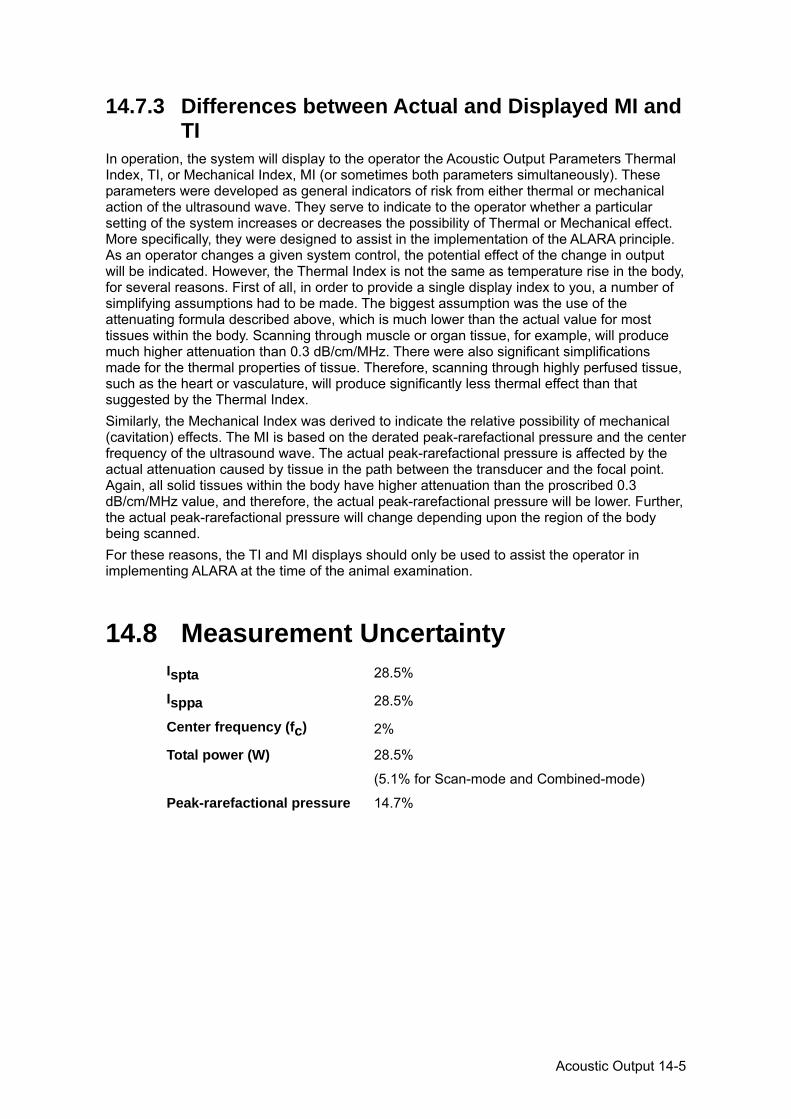
Acoustic Output 14-5
14.7.3 Differences between Actual and Displayed MI and TI
In operation, the system will display to the operator the Acoustic Output Parameters Thermal Index, TI, or Mechanical Index, MI (or sometimes both parameters simultaneously). These parameters were developed as general indicators of risk from either thermal or mechanical action of the ultrasound wave. They serve to indicate to the operator whether a particular setting of the system increases or decreases the possibility of Thermal or Mechanical effect. More specifically, they were designed to assist in the implementation of the ALARA principle. As an operator changes a given system control, the potential effect of the change in output will be indicated. However, the Thermal Index is not the same as temperature rise in the body, for several reasons. First of all, in order to provide a single display index to you, a number of simplifying assumptions had to be made. The biggest assumption was the use of the attenuating formula described above, which is much lower than the actual value for most tissues within the body. Scanning through muscle or organ tissue, for example, will produce much higher attenuation than 0.3 dB/cm/MHz. There were also significant simplifications made for the thermal properties of tissue. Therefore, scanning through highly perfused tissue, such as the heart or vasculature, will produce significantly less thermal effect than that suggested by the Thermal Index. Similarly, the Mechanical Index was derived to indicate the relative possibility of mechanical (cavitation) effects. The MI is based on the derated peak-rarefactional pressure and the center frequency of the ultrasound wave. The actual peak-rarefactional pressure is affected by the actual attenuation caused by tissue in the path between the transducer and the focal point. Again, all solid tissues within the body have higher attenuation than the proscribed 0.3 dB/cm/MHz value, and therefore, the actual peak-rarefactional pressure will be lower. Further, the actual peak-rarefactional pressure will change depending upon the region of the body being scanned. For these reasons, the TI and MI displays should only be used to assist the operator in implementing ALARA at the time of the animal examination.
14.8 Measurement Uncertainty Ispta 28.5%
Isppa 28.5%
Center frequency (fc) 2%
Total power (W) 28.5%
(5.1% for Scan-mode and Combined-mode)
Peak-rarefactional pressure 14.7%

14-6 Acoustic Output
14.9 References for Acoustic Power and Safety
1. “Bioeffects and Safety of Diagnostic Ultrasound” issued by AIUM in 1993 2. “Medical Ultrasound Safety” issued by AIUM in 1994 3. "Acoustic Output Measurement Standard for Diagnostic Ultrasound Equipment, Revision 3" issued by AIUM/NEMA in 2004 4. "Standard for real-time display of thermal and mechanical acoustic output indices on diagnostic ultrasound equipment, Revision 2" issued by AIUM/NEMA in 2004 5. "Information for Manufacturers Seeking Marketing Clearance of Diagnostic Ultrasound Systems and Transducers" issued by FDA in 2008. 6. “Medical electrical equipment – Part 2-37: Particular requirements for the safety of ultrasonic medical diagnostic and monitoring equipment” issued by IEC in 2005.

Guidance and Manufacturer’s Declaration 15-1
15 Guidance and Manufacturer’s Declaration
The system complies with the EMC standard IEC60601-1-2: 2007.
WARNING: The use of unapproved accessories may diminish system performance.
NOTE: 1 Use of accessories, probes, and cables other than those specified may result in increased emission or decreased immunity of system.
2 The system or its components should not be used adjacent to or stacked with other equipment. If adjacent or stacked use is necessary, the system or its components should be observed to verify normal operation in the configuration in which it will be used.
3 The system needs special precautions regarding EMC and needs to be installed and put into service according to the EMC information provided below.
4 Other devices may interfere with this system even though they meet the requirements of CISPR.
5 Preventing conducted RF immunity. Due to technological limitations, the conducted RF immunity level are limited to 1Vrms level, conducted RF interference above 1Vrms may cause wrong diagnosis and measurements. We suggest that you position system further from sources of conducted RF noise.
6 Operation of system, in the case that the animal physiological signal is lower than the minimum amplitude or value specified in the product specifications, may cause inaccurate results.
7 Portable and mobile RF communications equipment can affects system. See tables 1, 2, 3, and 4 below.
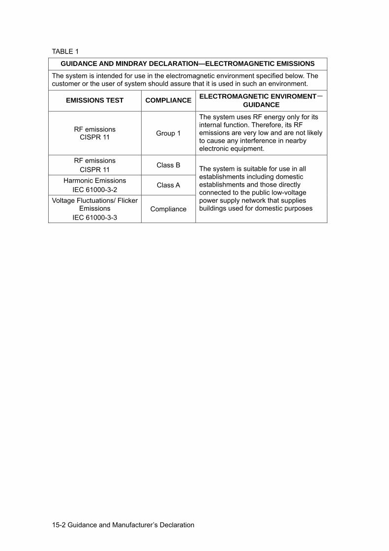
15-2 Guidance and Manufacturer’s Declaration
TABLE 1
GUIDANCE AND MINDRAY DECLARATION—ELECTROMAGNETIC EMISSIONS
The system is intended for use in the electromagnetic environment specified below. The customer or the user of system should assure that it is used in such an environment.
EMISSIONS TEST COMPLIANCE ELECTROMAGNETIC ENVIROMENT-GUIDANCE
RF emissions CISPR 11 Group 1
The system uses RF energy only for its internal function. Therefore, its RF emissions are very low and are not likely to cause any interference in nearby electronic equipment.
RF emissions CISPR 11
Class B The system is suitable for use in all establishments including domestic establishments and those directly connected to the public low-voltage power supply network that supplies buildings used for domestic purposes
Harmonic Emissions IEC 61000-3-2
Class A
Voltage Fluctuations/ Flicker Emissions
IEC 61000-3-3 Compliance
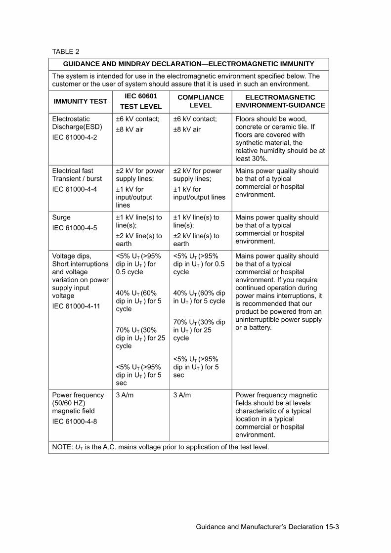
Guidance and Manufacturer’s Declaration 15-3
TABLE 2
GUIDANCE AND MINDRAY DECLARATION—ELECTROMAGNETIC IMMUNITY
The system is intended for use in the electromagnetic environment specified below. The customer or the user of system should assure that it is used in such an environment.
IMMUNITY TEST IEC 60601
TEST LEVEL COMPLIANCE
LEVEL ELECTROMAGNETIC
ENVIRONMENT-GUIDANCE
Electrostatic Discharge(ESD) IEC 61000-4-2
±6 kV contact; ±8 kV air
±6 kV contact; ±8 kV air
Floors should be wood, concrete or ceramic tile. If floors are covered with synthetic material, the relative humidity should be at least 30%.
Electrical fast Transient / burst IEC 61000-4-4
±2 kV for power supply lines; ±1 kV for input/output lines
±2 kV for power supply lines; ±1 kV for input/output lines
Mains power quality should be that of a typical commercial or hospital environment.
Surge IEC 61000-4-5
±1 kV line(s) to line(s); ±2 kV line(s) to earth
±1 kV line(s) to line(s); ±2 kV line(s) to earth
Mains power quality should be that of a typical commercial or hospital environment.
Voltage dips, Short interruptions and voltage variation on power supply input voltage IEC 61000-4-11
<5% UT (>95% dip in UT ) for 0.5 cycle 40% UT (60% dip in UT ) for 5 cycle 70% UT (30% dip in UT ) for 25 cycle <5% UT (>95% dip in UT ) for 5 sec
<5% UT (>95% dip in UT ) for 0.5 cycle 40% UT (60% dip in UT ) for 5 cycle 70% UT (30% dip in UT ) for 25 cycle <5% UT (>95% dip in UT ) for 5 sec
Mains power quality should be that of a typical commercial or hospital environment. If you require continued operation during power mains interruptions, it is recommended that our product be powered from an uninterruptible power supply or a battery.
Power frequency (50/60 HZ) magnetic field IEC 61000-4-8
3 A/m 3 A/m Power frequency magnetic fields should be at levels characteristic of a typical location in a typical commercial or hospital environment.
NOTE: UT is the A.C. mains voltage prior to application of the test level.
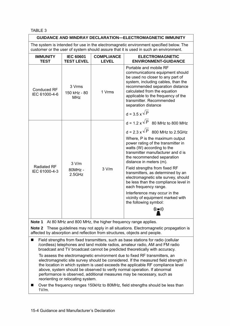
15-4 Guidance and Manufacturer’s Declaration
TABLE 3
GUIDANCE AND MINDRAY DECLARATION—ELECTROMAGNETIC IMMUNITY
The system is intended for use in the electromagnetic environment specified below. The customer or the user of system should assure that it is used in such an environment.
IMMUNITY TEST
IEC 60601 TEST LEVEL
COMPLIANCE LEVEL
ELECTROMAGNETIC ENVIRONMENT-GUIDANCE
Conduced RF IEC 61000-4-6
3 Vrms 150 kHz - 80
MHz 1 Vrms
Portable and mobile RF communications equipment should be used no closer to any part of system, including cables, than the recommended separation distance calculated from the equation applicable to the frequency of the transmitter. Recommended separation distance
d = 3.5 x P
d = 1.2 x P 80 MHz to 800 MHz
d = 2.3 x P 800 MHz to 2.5GHz Where, P is the maximum output power rating of the transmitter in watts (W) according to the transmitter manufacturer and d is the recommended separation distance in meters (m). Field strengths from fixed RF transmitters, as determined by an electromagnetic site survey, should be less than the compliance level in each frequency range. Interference may occur in the vicinity of equipment marked with the following symbol:
Radiated RF IEC 61000-4-3
3 V/m 80MHz - 2.5GHz
3 V/m
Note 1 At 80 MHz and 800 MHz, the higher frequency range applies. Note 2 These guidelines may not apply in all situations. Electromagnetic propagation is affected by absorption and reflection from structures, objects and people.
Field strengths from fixed transmitters, such as base stations for radio (cellular /cordless) telephones and land mobile radios, amateur radio, AM and FM radio broadcast and TV broadcast cannot be predicted theoretically with accuracy. To assess the electromagnetic environment due to fixed RF transmitters, an electromagnetic site survey should be considered. If the measured field strength in the location in which system is used exceeds the applicable RF compliance level above, system should be observed to verify normal operation. If abnormal performance is observed, additional measures may be necessary, such as reorienting or relocating system.
Over the frequency ranges 150kHz to 80MHz, field strengths should be less than 1V/m.
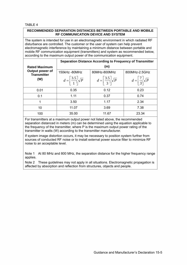
Guidance and Manufacturer’s Declaration 15-5
TABLE 4
RECOMMENDED SEPARATION DISTANCES BETWEEN PORTABLE AND MOBILE RF COMMUNICATION DEVICE AND SYSTEM
The system is intended for use in an electromagnetic environment in which radiated RF disturbance are controlled. The customer or the user of system can help prevent electromagnetic interference by maintaining a minimum distance between portable and mobile RF communication equipment (transmitters) and system as recommended below, according to the maximum output power of the communication equipment.
Rated Maximum Output power of
Transmitter (W)
Separation Distance According to Frequency of Transmitter (m)
150kHz -80MHz
Pd ⎥⎦⎤
⎢⎣⎡=
15.3
80MHz-800MHz
Pd ⎥⎦⎤
⎢⎣⎡=
35.3
800MHz-2.5GHz
Pd ⎥⎦⎤
⎢⎣⎡=37
0.01 0.35 0.12 0.23
0.1 1.11 0.37 0.74
1 3.50 1.17 2.34
10 11.07 3.69 7.38
100 35.00 11.67 23.34
For transmitters at a maximum output power not listed above, the recommended separation distanced in meters (m) can be determined using the equation applicable to the frequency of the transmitter, where P is the maximum output power rating of the transmitter in watts (W) according to the transmitter manufacturer. If system image distortion occurs, it may be necessary to position system further from sources of conducted RF noise or to install external power source filter to minimize RF noise to an acceptable level. Note 1 At 80 MHz and 800 MHz, the separation distance for the higher frequency range applies. Note 2 These guidelines may not apply in all situations. Electromagnetic propagation is affected by absorption and reflection from structures, objects and people.

System Maintenance 16-1
16 System Maintenance
Routine system maintenance shall be carried out by the user. Service maintenance will be provided by Mindray service engineers while the system is under warranty. System maintenance after the warranty has expired is the full responsibility of the owner / operator.
WARNING: 1. Only an authorized Mindray service engineer can perform maintenance not specified in this operator’s manual.
2. For the sake of the system performance and safety, you should perform periodical checks for the system.
16.1 Daily Maintenance You are responsible for daily maintenance.
16.1.1 Cleaning the System
WARNING: Before cleaning the system, be sure to turn off the power and disconnect the power cord from the outlet. If you clean the system while the power is “On”, it may result in electric shock.
Cleaning the probe Please refer to the operator’s manual of the corresponding transducer or “12.1.5 Probes Cleaning and Disinfection” to perform cleaning and disinfection.
Cleaning the probe cable a) Use soft dry cloth to wipe off stains from the probe cable. b) If it is difficult to clean the stains thoroughly, use soft cloth dipped with mild
detergent, and then let the cable air dry. Cleaning the monitor
Using a soft cloth, apply a glass cleaner directly to the cloth and wipe down the monitor to remove finger marks, dust and smudges. Allow the monitor to air-dry.
NOTE: 1. Do not use hydrocarbon glass cleaner or cleaner for OA (Office Automation) equipment to clean the monitor. These substances may cause deterioration of the monitor.
2. Keyboard on the control panel should be cleaned periodically, otherwise, keys maybe blocked by dirt and buzzer dings, keys don’t work.
Cleaning the control panel, cover and bracket Use dry soft cloth to clean the surface of the system. If the system is dirty, moisten the soft cloth with a mild or neutral detergent and wipe off any stains. Use dry soft cloth to remove any moisture and allow all hard surfaces to completely air-dry.
Cleaning the trackball Tool: tissue paper or dry cotton cloth Method:
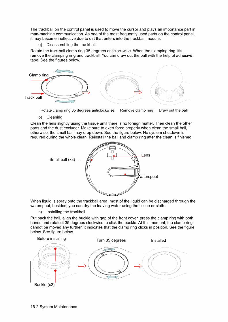
16-2 System Maintenance
The trackball on the control panel is used to move the cursor and plays an importance part in man-machine communication. As one of the most frequently used parts on the control panel, it may become ineffective due to dirt that enters into the trackball module.
a) Disassembling the trackball: Rotate the trackball clamp ring 35 degrees anticlockwise. When the clamping ring lifts, remove the clamping ring and trackball. You can draw out the ball with the help of adhesive tape. See the figures below.
Rotate clamp ring 35 degrees anticlockwise Remove clamp ring Draw out the ball
b) Cleaning Clean the lens slightly using the tissue until there is no foreign matter. Then clean the other parts and the dust excluder. Make sure to exert force properly when clean the small ball, otherwise, the small ball may drop down. See the figure below. No system shutdown is required during the whole clean. Reinstall the ball and clamp ring after the clean is finished.
When liquid is spray onto the trackball area, most of the liquid can be discharged through the waterspout, besides, you can dry the leaving water using the tissue or cloth.
c) Installing the trackball Put back the ball, align the buckle with gap of the front cover, press the clamp ring with both hands and rotate it 35 degrees clockwise to click the buckle. At this moment, the clamp ring cannot be moved any further, it indicates that the clamp ring clicks in position. See the figure below. See figure below.
Track ball
Lens
Waterspout
Clamp ring
Buckle (x2)
Turn 35 degrees l k i
Installed Before installing
Small ball (x3)
System Maintenance 16-3
16.1.2 Checking Transducer Check the transducer connector for crack every time before use. DO NOT use the transducer if a crack is inspected. A thoroughly inspection to the transducer including cable and connector is required every time when you clean the transducer.
16.1.3 Backup of the System Hard Drive To prevent deterioration or loss of data stored in the system hard drive, create a backup copy of the hard drive at regular intervals.
16.2 Maintenance Checks by Service Engineer
The following checks must be performed to ensure and maintain system safety and performance. Please contact Mindray Customer Service Department or sales representative to schedule and carry out these checks.
Check Category Check Item
Cleaning Interior of the system Peripherals
Electric safety
Ground leakage current Enclosure leakage current Animal leakage current Animal leakage current (110% supply voltage on applied part) Animal auxiliary leakage current
Mechanical safety
Monitor mounting mechanism Control panel Mounting mechanism for the peripheral devices Check other mechanical structures Check the transducer appearance
Image recording Images in each mode Image recording by using the standard probe
16.3 Consumables and Periodic Part Replacement
This system contains some consumables and parts requiring periodic replacement. Before replacing them, please contact Mindray Customer Service Department or sales representative for instructions.
16.4 Troubleshooting To ensure proper system operation and function, it is recommended that a maintenance and inspection plan be established to periodically check the safety of the system. If any system malfunction is experienced, contact Mindray Customer Service Department or sales representative. If any persistent system malfunction is experienced, e.g. an onscreen error message, blank imaging screen, absent menus, please refer to the following table below. If the failure cannot be eliminated, please contact Mindray Customer Service Department or sales representative.
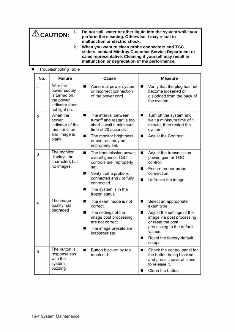
16-4 System Maintenance
CAUTION: 1. Do not spill water or other liquid into the system while you perform the cleaning. Otherwise it may result in malfunction or electric shock.
2. When you want to clean probe connectors and TGC sliders, contact Mindray Customer Service Department or sales representative. Cleaning it yourself may result in malfunction or degradation of the performance.
Troubleshooting Table
No. Failure Cause Measure
1 After the power supply is turned on, the power indicator does not light on.
Abnormal power system or incorrect connection of the power cord.
Verify that the plug has not become loosened or dislodged from the back of the system.
2 When the power indicator of the monitor is on and image is blank.
The interval between turnoff and restart is too short – wait a minimum time of 20 seconds.
The monitor brightness or contrast may be improperly set.
Turn off the system and wait a minimum time of 1 minute, then restart the system.
Adjust the Contrast
3 The monitor displays the characters but no images.
The transmission power, overall gain or TGC controls are improperly set.
Verify that a probe is connected and / or fully connected.
The system is in the frozen status.
Adjust the transmission power, gain or TGC control.
Ensure proper probe connection.
Unfreeze the image.
4 The image quality has degraded
The exam mode is not correct.
The settings of the image post processing are not correct.
The image presets are inappropriate
Select an appropriate exam type.
Adjust the settings of the image via post processing or reset the post processing to the default values.
Reset the factory default setups.
5 The button is responseless with the system buzzing
Button blocked by too much dirt
Check the control panel for the button being blocked and press it several times to release it.
Clean the button

Electrical Safety Inspection A-1
Appendix A Electrical Safety Inspection
The following electrical safety tests are recommended as part of a comprehensive preventive maintenance program. They are a proven means of detecting abnormalities that, if undetected, could prove dangerous to either the animal or the operator. Additional tests may be required according to local regulations. All tests can be performed using commercially available safety analyzer test equipment. These procedures assume the use of a 601PROXL International Safety Analyzer or equivalent safety analyzer. Other popular testers complying with IEC 60601-1 used in Europe such as Fluke, Metron, or Gerb may require modifications to the procedure. Follow the instructions of the analyzer manufacturer. The electrical safety inspection should be periodically performed every two years. The safety analyzer also proves to be an excellent troubleshooting tool to detect abnormalities of line voltage and grounding, as well as total current loads.
A.1 Power Cord Plug A.1.1 The Power Plug
Test Item Acceptance Criteria
The power plug
The power plug pins No broken or bent pin. No discolored pins.
The plug body No physical damage to the plug body.
The strain relief No physical damage to the strain relief. No plug warmth for device in use.
The power plug No loose connections.
The power cord
No physical damage to the cord. No deterioration to the cord.
For devices with detachable power cords, inspect the connection at the device.
For devices with non-detachable power cords, inspect the strain relief at the device.
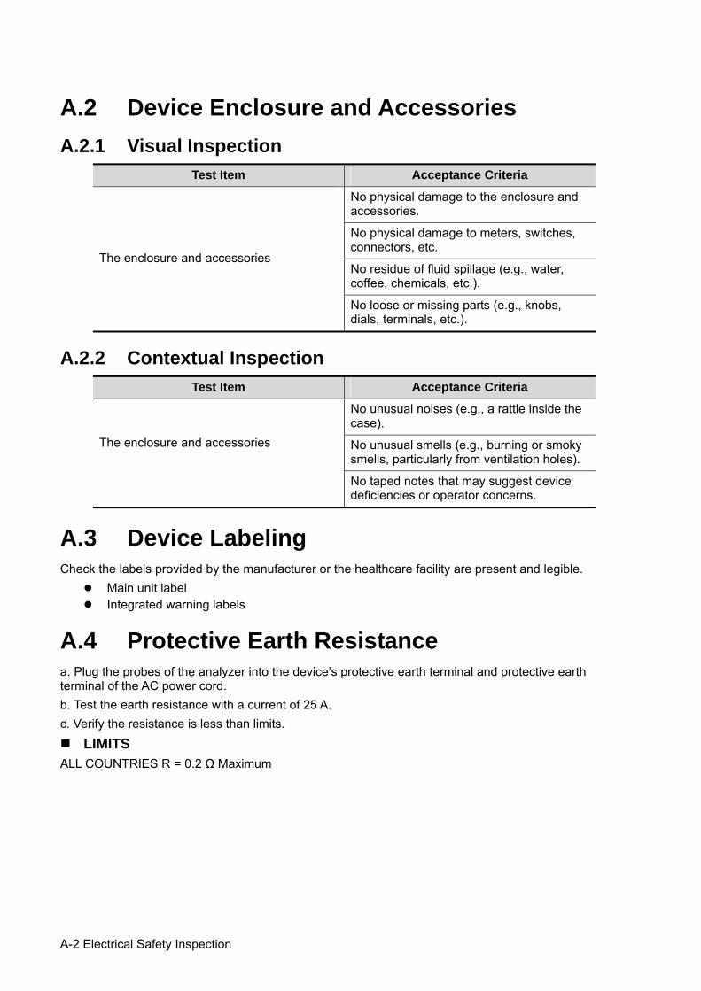
A-2 Electrical Safety Inspection
A.2 Device Enclosure and Accessories A.2.1 Visual Inspection
Test Item Acceptance Criteria
The enclosure and accessories
No physical damage to the enclosure and accessories.
No physical damage to meters, switches, connectors, etc.
No residue of fluid spillage (e.g., water, coffee, chemicals, etc.).
No loose or missing parts (e.g., knobs, dials, terminals, etc.).
A.2.2 Contextual Inspection Test Item Acceptance Criteria
The enclosure and accessories
No unusual noises (e.g., a rattle inside the case).
No unusual smells (e.g., burning or smoky smells, particularly from ventilation holes).
No taped notes that may suggest device deficiencies or operator concerns.
A.3 Device Labeling Check the labels provided by the manufacturer or the healthcare facility are present and legible.
Main unit label Integrated warning labels
A.4 Protective Earth Resistance a. Plug the probes of the analyzer into the device’s protective earth terminal and protective earth terminal of the AC power cord. b. Test the earth resistance with a current of 25 A. c. Verify the resistance is less than limits.
LIMITS ALL COUNTRIES R = 0.2 Ω Maximum
Electrical Safety Inspection A-3
A.5 Earth Leakage Test Run an Earth Leakage test on the device being tested before performing any other leakage tests. The following outlet conditions apply when performing the Earth Leakage test.
normal polarity (Normal Condition); reverse polarity (Normal Condition); normal polarity with open neutral (Single Fault Condition); reverse polarity with open neutral (Single Fault Condition).
LIMITS For UL60601-1,
300 μA in Normal Condition. 1000 μA in Single Fault Condition.
For IEC60601-1, 500 μA in Normal Condition. 1000 μA in Single Fault Condition.
A.6 Enclosure Leakage Test The following outlet conditions apply when performing the Enclosure Leakage test.
normal polarity (Normal Condition); reverse polarity (Normal Condition); normal polarity with open neutral (Single Fault Condition); reverse polarity with open neutral (Single Fault Condition); normal polarity with open earth (Single Fault Condition); reverse polarity with open earth (Single Fault Condition).
LIMITS For UL60601-1,
100μA in Normal Condition. 300 μA in Single Fault Condition.
For IEC60601-1: 100μA in Normal Condition. 500 μA in Single Fault Condition.
A.7 Patient Leakage Current Patient leakage currents are measured between a selected applied part and mains earth. All measurements have a true RMS only. The following outlet conditions apply when performing the Patient Leakage Current test.
normal polarity (Normal Condition); reverse polarity (Normal Condition); normal polarity with open neutral (Single Fault Condition); reverse polarity with open neutral (Single Fault Condition); normal polarity with open earth (Single Fault Condition); reverse polarity with open earth (Single Fault Condition).
A-4 Electrical Safety Inspection
LIMITS
For BF applied parts, 100μA in Normal Condition. 500μA in Single Fault Condition.
A.8 Mains on Applied Part Leakage The Mains on Applied Part test applies a test voltage, which is 110% of the mains voltage, through a limiting resistance, to selected applied part terminals. Current measurements are then taken between the selected applied part and earth. Measurements are taken with the test voltage (110% of mains) to applied parts in the normal and reverse polarity conditions. The following outlet conditions apply when performing the Mains on Applied Part test.
Normal Polarity; Reversed Polarity.
LIMITS
For BF applied parts: 5000 μA.
A.9 Patient Auxiliary Current Patient Auxiliary currents are measured between any selected Applied Part connector and the remaining Applied Part connectors. All measurements may have a true RMS only response. The following outlet conditions apply when performing the Patient Auxiliary Current test.
normal polarity (Normal Condition); reverse polarity (Normal Condition); normal polarity with open neutral (Single Fault Condition); reverse polarity with open neutral (Single Fault Condition); normal polarity with open earth (Single Fault Condition); reverse polarity with open earth (Single Fault Condition).
LIMITS
For BF applied parts, 100μA in Normal Condition. 500μA in Single Fault Condition.
Note: Make sure the safety analyzer is authorized comply with requirement of IEC61010-1. Follow the instructions of the analyzer manufacturer.
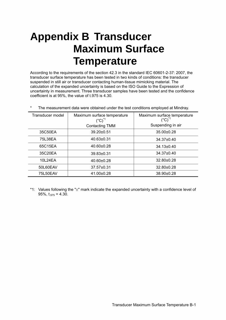
Transducer Maximum Surface Temperature B-1
Appendix B Transducer Maximum Surface Temperature
According to the requirements of the section 42.3 in the standard IEC 60601-2-37: 2007, the transducer surface temperature has been tested in two kinds of conditions: the transducer suspended in still air or transducer contacting human-tissue mimicking material. The calculation of the expanded uncertainty is based on the ISO Guide to the Expression of uncertainty in measurement. Three transducer samples have been tested and the confidence coefficient is at 95%, the value of t.975 is 4.30. * The measurement data were obtained under the test conditions employed at Mindray.
Transducer model Maximum surface temperature (°C)*1
Contacting TMM
Maximum surface temperature (°C)*1
Suspending in air
35C50EA 39.20±0.51 35.00±0.28
75L38EA 40.63±0.31 34.37±0.40
65C15EA 40.60±0.28 34.13±0.40
35C20EA 39.83±0.31 34.37±0.40
10L24EA 40.60±0.28 32.80±0.28
50L60EAV 37.57±0.31 32.80±0.28 75L50EAV 41.00±0.28 38.90±0.28
*1: Values following the "±" mark indicate the expanded uncertainty with a confidence level of 95%, t.975 = 4.30.

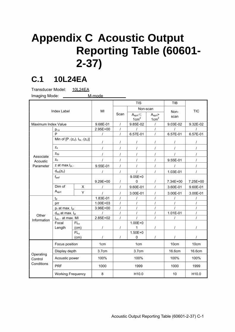
Acoustic Output Reporting Table (60601-2-37) C-1
Appendix C Acoustic Output Reporting Table (60601-2-37)
C.1 10L24EA Transducer Model: 10L24EA Imaging Mode: M-mode
Index Label MI
TIS TIB
TIC Scan
Non-scan Non- scan Aaprt≤
1cm2 Aaprt> 1cm2
Maximum Index Value 9.68E-01 / 9.85E-02 / 9.03E-02 9.32E-02
Associate Acoustic
Parameter
pr.a 2.95E+00 / / / / / P / / 6.57E-01 / 6.57E-01 6.57E-01Min of [Pα(zs), Ita,α(zs)]
/ / / / / / zs / / / / / / zbp / / / / / / zb / / / / 9.55E-01 / z at max.Ipi,α 9.55E-01 / / / / / deq(zb) / / / / 1.03E-01 / fawf
9.29E+00 / 9.05E+0
0 / 7.34E+00 7.25E+00Dim of Aaprt
X / / 9.60E-01 / 3.60E-01 9.60E-01Y / / 3.00E-01 / 3.00E-01 3.00E-01
Other Information
td 1.83E-01 / / / / / prr 1.00E+03 / / / / / pr at max. Ipi 3.96E+00 / / / / / deq at max. Ipi / / / / 1.01E-01 / Ipa,α at max. MI 2.85E+02 / / / / / Focal Length
FLx (cm) / /
1.00E+01 / / /
FLy (cm) / /
1.50E+00 / / /
Operating Control Conditions
Focus position 1cm 1cm 10cm 10cm
Display depth 3.7cm 3.7cm 16.6cm 16.6cm
Acoustic power 100% 100% 100% 100%
PRF 1000 1999 1000 1999
Working Frequency 8 H10.0 10 H10.0
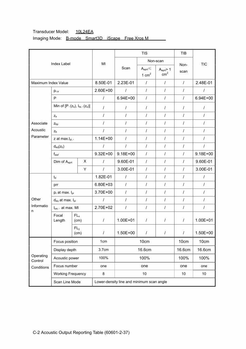
C-2 Acoustic Output Reporting Table (60601-2-37)
Transducer Model: 10L24EA Imaging Mode: B-mode Smart3D iScape Free Xros M
Index Label MI
TIS TIB
TIC Scan
Non-scan Non-
scan Aaprt≤
1 cm2 Aaprt> 1
cm2
Maximum Index Value 8.50E-01 2.23E-01 / / / 2.48E-01
Associate
Acoustic
Parameter
pr.a 2.60E+00 / / / / /
P / 6.94E+00 / / / 6.94E+00
Min of [Pα(zs), Ita,α(zs)] / / / / / /
zs / / / / / /
zbp / / / / / /
zb / / / / / /
z at max.Ipi,α 1.14E+00 / / / / /
deq(zb) / / / / / /
fawf 9.32E+00 9.18E+00 / / / 9.18E+00
Dim of Aaprt X / 9.60E-01 / / / 9.60E-01
Y / 3.00E-01 / / / 3.00E-01
Other
Information
td 1.82E-01 / / / / /
prr 6.80E+03 / / / / /
pr at max. Ipi 3.70E+00 / / / / /
deq at max. Ipi / / / / / /
Ipa,α at max. MI 2.70E+02 / / / / /
Focal Length
FLx (cm) / 1.00E+01 / / / 1.00E+01
FLy (cm) / 1.50E+00 / / / 1.50E+00
Operating Control
Conditions
Focus position 1cm 10cm 10cm 10cm
Display depth 3.7cm 16.6cm 16.6cm 16.6cm
Acoustic power 100% 100% 100% 100%
Focus number one one one one
Working Frequency 8 10 10 10
Scan Line Mode Lower-density line and minimum scan angle
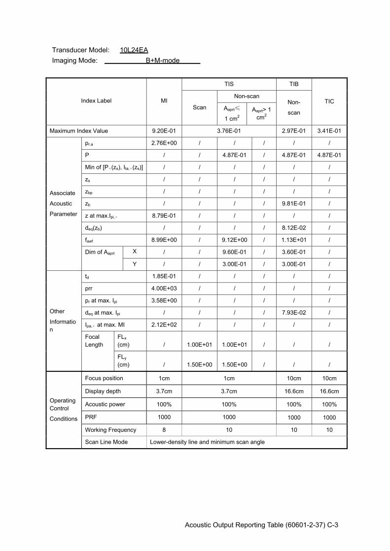
Acoustic Output Reporting Table (60601-2-37) C-3
Transducer Model: 10L24EA Imaging Mode: B+M-mode
Index Label MI
TIS TIB
TIC Scan
Non-scan Non-
scan Aaprt≤
1 cm2 Aaprt> 1
cm2
Maximum Index Value 9.20E-01 3.76E-01 2.97E-01 3.41E-01
Associate
Acoustic
Parameter
pr.a 2.76E+00 / / / / /
P / / 4.87E-01 / 4.87E-01 4.87E-01
Min of [Pα(zs), Ita,α(zs)] / / / / / /
zs / / / / / /
zbp / / / / / /
zb / / / / 9.81E-01 /
z at max.Ipi,α 8.79E-01 / / / / /
deq(zb) / / / / 8.12E-02 /
fawf 8.99E+00 / 9.12E+00 / 1.13E+01 /
Dim of Aaprt X / / 9.60E-01 / 3.60E-01 /
Y / / 3.00E-01 / 3.00E-01 /
Other
Information
td 1.85E-01 / / / / /
prr 4.00E+03 / / / / /
pr at max. Ipi 3.58E+00 / / / / /
deq at max. Ipi / / / / 7.93E-02 /
Ipa,α at max. MI 2.12E+02 / / / / /
Focal Length
FLx (cm) / 1.00E+01 1.00E+01 / / /
FLy (cm) / 1.50E+00 1.50E+00 / / /
Operating Control
Conditions
Focus position 1cm 1cm 10cm 10cm
Display depth 3.7cm 3.7cm 16.6cm 16.6cm
Acoustic power 100% 100% 100% 100%
PRF 1000 1000 1000 1000
Working Frequency 8 10 10 10
Scan Line Mode Lower-density line and minimum scan angle
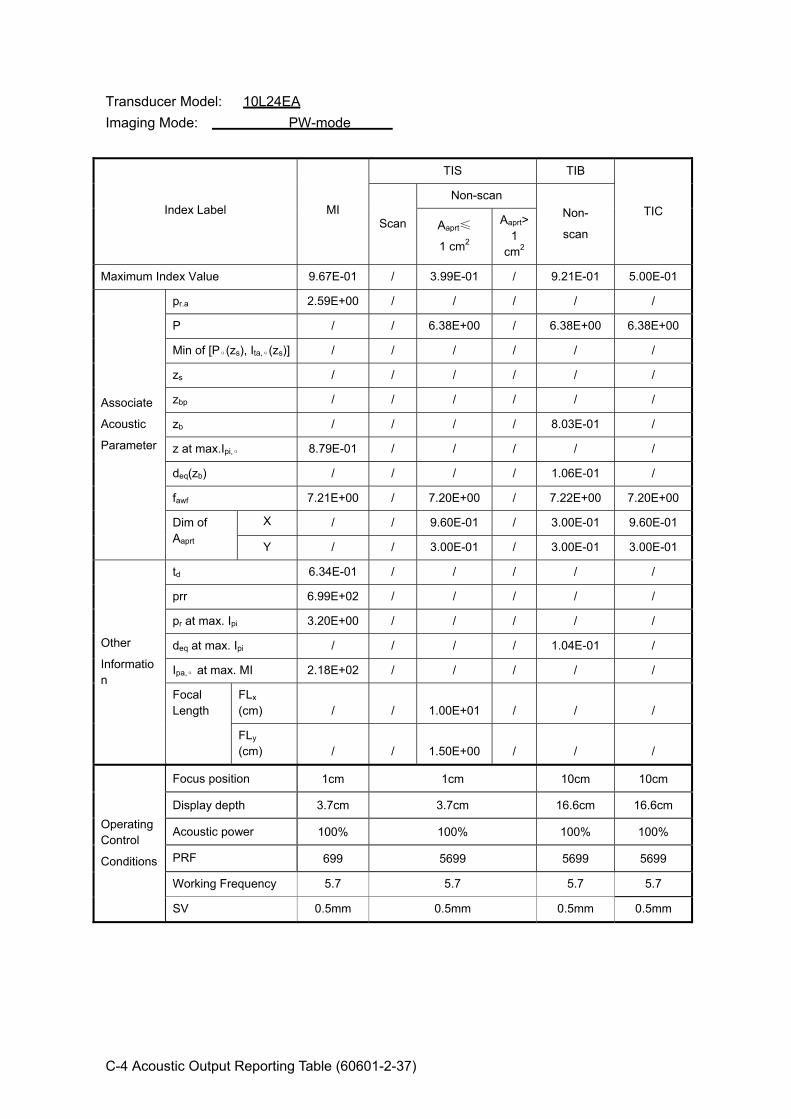
C-4 Acoustic Output Reporting Table (60601-2-37)
Transducer Model: 10L24EA Imaging Mode: PW-mode
Index Label MI
TIS TIB
TIC Scan
Non-scan Non-
scan Aaprt≤
1 cm2
Aaprt>1
cm2
Maximum Index Value 9.67E-01 / 3.99E-01 / 9.21E-01 5.00E-01
Associate
Acoustic
Parameter
pr.a 2.59E+00 / / / / /
P / / 6.38E+00 / 6.38E+00 6.38E+00
Min of [Pα(zs), Ita,α(zs)] / / / / / /
zs / / / / / /
zbp / / / / / /
zb / / / / 8.03E-01 /
z at max.Ipi,α 8.79E-01 / / / / /
deq(zb) / / / / 1.06E-01 /
fawf 7.21E+00 / 7.20E+00 / 7.22E+00 7.20E+00
Dim of Aaprt
X / / 9.60E-01 / 3.00E-01 9.60E-01
Y / / 3.00E-01 / 3.00E-01 3.00E-01
Other
Information
td 6.34E-01 / / / / /
prr 6.99E+02 / / / / /
pr at max. Ipi 3.20E+00 / / / / /
deq at max. Ipi / / / / 1.04E-01 /
Ipa,α at max. MI 2.18E+02 / / / / /
Focal Length
FLx (cm) / / 1.00E+01 / / /
FLy (cm) / / 1.50E+00 / / /
Operating Control
Conditions
Focus position 1cm 1cm 10cm 10cm
Display depth 3.7cm 3.7cm 16.6cm 16.6cm
Acoustic power 100% 100% 100% 100%
PRF 699 5699 5699 5699
Working Frequency 5.7 5.7 5.7 5.7
SV 0.5mm 0.5mm 0.5mm 0.5mm

Acoustic Output Reporting Table (60601-2-37) C-5
Transducer Model: 10L24EA Imaging Mode: B+PW-mode
Index Label MI
TIS TIB
TIC Scan
Non-scan
Non-scan Aaprt≤
1 cm2 Aaprt> 1
cm2
Maximum Index Value 1.02E+00 7.14E-01 9.80E-01 7.18E-01
Associate
Acoustic
Parameter
pr.a 2.74E+00 / / / / /
P / / 7.63E+00 / 7.63E+00 7.63E+00
Min of [Pα(zs), Ita,α(zs)] / / / / / /
zs / / / / / /
zbp / / / / / /
zb / / / / 9.09E-01 /
z at max.Ipi,α 8.79E-01 / / / / /
deq(zb) / / / / 1.13E-01 /
fawf 7.23E+00 / 7.22E+00 / 7.22E+00 /
Dim of Aaprt X / / 9.60E-01 / 3.60E-01 /
Y / / 3.00E-01 / 3.00E-01 /
Other
Information
td 6.33E-01 / / / / /
prr 6.99E+02 / / / / /
pr at max. Ipi 3.38E+00 / / / / /
deq at max. Ipi / / / / 1.10E-01 /
Ipa,α at max. MI 2.47E+02 / / / / /
Focal Length
FLx (cm) / 1.00E+01 1.00E+01 / / /
FLy (cm) / 1.50E+00 1.50E+00 / / /
Operating Control
Conditions
B mode Focus /SV Position 1cm 1.5cm 10cm 10cm
Display depth 3.7cm 16.6cm 16.6cm 16.6cm
Acoustic power 100% 100% 100% 100%
PW PRF 699 2921 2921 2921
B Working Frequency 8 8 8 8
PW Working Frequency 5.7 5.7 5.7 5.7
PW SV 0.5mm 0.5mm
Scan Line Mode Lower-density line and minimum scan angle
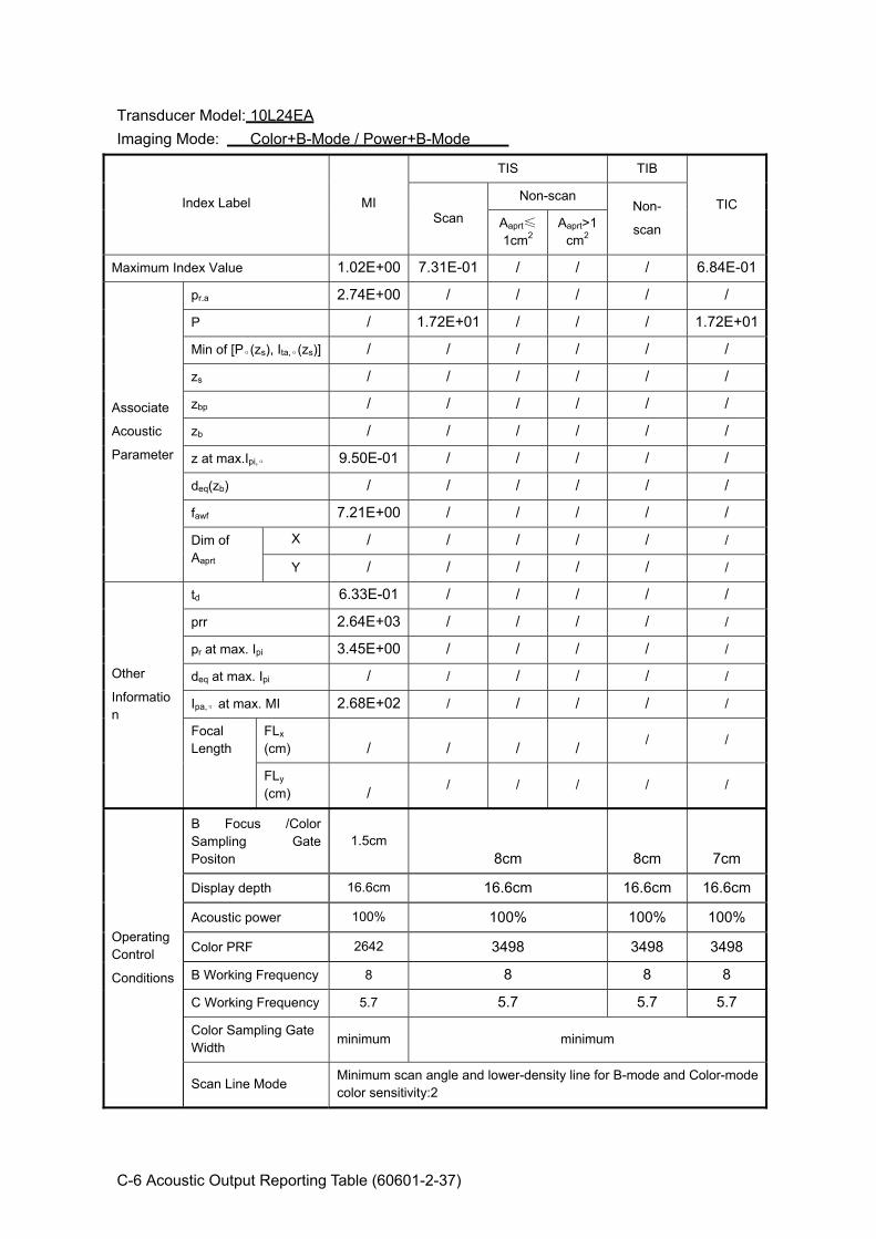
C-6 Acoustic Output Reporting Table (60601-2-37)
Transducer Model: 10L24EA Imaging Mode: Color+B-Mode / Power+B-Mode
Index Label MI
TIS TIB
TIC Scan
Non-scan Non-
scan Aaprt≤
1cm2 Aaprt>1
cm2
Maximum Index Value 1.02E+00 7.31E-01 / / / 6.84E-01
Associate
Acoustic
Parameter
pr.a 2.74E+00 / / / / /
P / 1.72E+01 / / / 1.72E+01
Min of [Pα(zs), Ita,α(zs)] / / / / / /
zs / / / / / /
zbp / / / / / /
zb / / / / / /
z at max.Ipi,α 9.50E-01 / / / / /
deq(zb) / / / / / /
fawf 7.21E+00 / / / / /
Dim of Aaprt
X / / / / / /
Y / / / / / /
Other
Information
td 6.33E-01 / / / / /
prr 2.64E+03 / / / / /
pr at max. Ipi 3.45E+00 / / / / /
deq at max. Ipi / / / / / /
Ipa,α at max. MI 2.68E+02 / / / / /
Focal Length
FLx (cm) / / / / / /
FLy (cm) / / / / / /
Operating Control
Conditions
B Focus /Color Sampling Gate Positon
1.5cm 8cm 8cm 7cm
Display depth 16.6cm 16.6cm 16.6cm 16.6cm
Acoustic power 100% 100% 100% 100%
Color PRF 2642 3498 3498 3498
B Working Frequency 8 8 8 8
C Working Frequency 5.7 5.7 5.7 5.7
Color Sampling Gate Width minimum minimum
Scan Line Mode Minimum scan angle and lower-density line for B-mode and Color-mode color sensitivity:2

Acoustic Output Reporting Table (60601-2-37) C-7
Transducer Model: 10L24EA Imaging Mode: Color+B+PW-Mode/Power+B+PW-Mode
Index Label MI
TIS TIB
TIC Scan
Non-scan Non- scan Aaprt≤1
cm2 Aaprt>1
cm2 Maximum Index Value 9.63E-01 4.26E-01 7.56E-01 5.87E-01
Associate Acoustic Parameter
pr.a 2.57E+00 / / / / / P / / 5.42E+00 / 5.42E+00 1.24E+01Min of [Pα(zs), Ita,α(zs)] / / / / / / zs / / / / / / zbp / / / / / / zb / / / / 8.37E-01 / z at max.Ipi,α 6.52E-01 / / / / / deq(zb) / / / / 1.08E-01 / fawf 7.19E+00 / 7.19E+00 / 7.23E+00 / Dim of Aaprt X / / 2.40E-01 / 3.00E-01 /
Y / / 3.00E-01 / 3.00E-01 /
Other Information
td 6.33E-01 / / / / / prr 1.28E+04 / / / / / pr at max. Ipi 3.01E+00 / / / / / deq at max. Ipi / / / / 1.07E-01 / Ipa,α at max. MI 2.05E+02 / / / / / Focal Length
FLx (cm) / / 5.00E-01 / / / FLy (cm) / / 1.50E+00 / / /
Operating Control Conditions
B Focus/PW SV/Color SG position
0.5cm 1cm 0.5cm 0.5cm
Display depth 3.7cm 3.7cm 3.7cm 3.7cm
Acoustic power 100% 100% 100% 100%
PRF PW:699C:
12767 PW:8273C:337 PW:699C:
19572 PW:699C:
19572 B Working Frequency
8 8 10 8 PW Working Frequency
5.7 5.7 5.7 5.7
C Working Frequency
5.7 5.7 6.6 5.7
PW SV/Color SG SV=0.5mm
SG minimum
SV=0.5mm SG minimum
Scan Line Mode Lower-density line and minimum scan angle
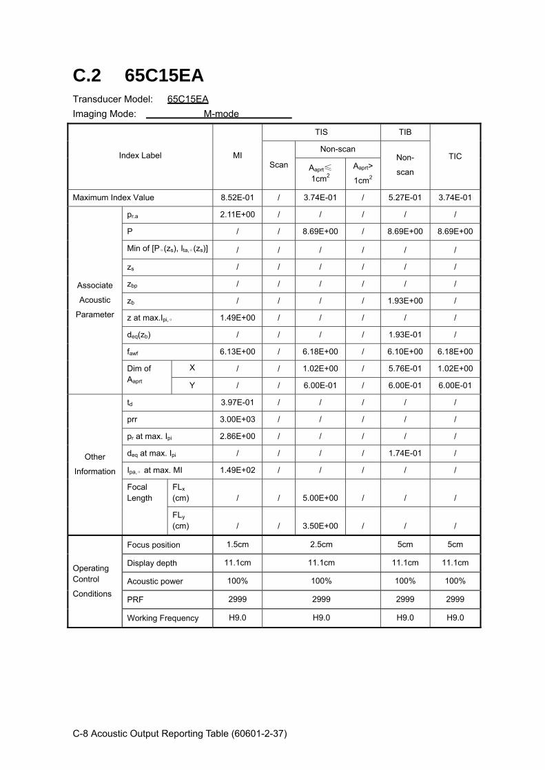
C-8 Acoustic Output Reporting Table (60601-2-37)
C.2 65C15EA Transducer Model: 65C15EA Imaging Mode: M-mode
Index Label MI
TIS TIB
TIC Scan
Non-scan Non-
scan Aaprt≤
1cm2 Aaprt>
1cm2
Maximum Index Value 8.52E-01 / 3.74E-01 / 5.27E-01 3.74E-01
Associate
Acoustic
Parameter
pr.a 2.11E+00 / / / / /
P / / 8.69E+00 / 8.69E+00 8.69E+00
Min of [Pα(zs), Ita,α(zs)] / / / / / /
zs / / / / / /
zbp / / / / / /
zb / / / / 1.93E+00 /
z at max.Ipi,α 1.49E+00 / / / / /
deq(zb) / / / / 1.93E-01 /
fawf 6.13E+00 / 6.18E+00 / 6.10E+00 6.18E+00
Dim of Aaprt
X / / 1.02E+00 / 5.76E-01 1.02E+00
Y / / 6.00E-01 / 6.00E-01 6.00E-01
Other
Information
td 3.97E-01 / / / / /
prr 3.00E+03 / / / / /
pr at max. Ipi 2.86E+00 / / / / /
deq at max. Ipi / / / / 1.74E-01 /
Ipa,α at max. MI 1.49E+02 / / / / /
Focal Length
FLx (cm) / / 5.00E+00 / / /
FLy (cm) / / 3.50E+00 / / /
Operating Control
Conditions
Focus position 1.5cm 2.5cm 5cm 5cm
Display depth 11.1cm 11.1cm 11.1cm 11.1cm
Acoustic power 100% 100% 100% 100%
PRF 2999 2999 2999 2999
Working Frequency H9.0 H9.0 H9.0 H9.0
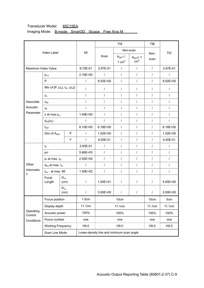
Acoustic Output Reporting Table (60601-2-37) C-9
Transducer Model: 65C15EA Imaging Mode: B-mode Smart3D iScape Free Xros M
Index Label MI
TIS TIB
TIC Scan
Non-scan Non-
scan Aaprt≤
1 cm2 Aaprt> 1
cm2
Maximum Index Value 8.75E-01 2.97E-01 / / / 2.67E-01
Associate
Acoustic
Parameter
pr.a 2.16E+00 / / / / /
P / 9.52E+00 / / / 9.52E+00
Min of [Pα(zs), Ita,α(zs)] / / / / / /
zs / / / / / /
zbp / / / / / /
zb / / / / / /
z at max.Ipi,α 1.49E+00 / / / / /
deq(zb) / / / / / /
fawf 6.10E+00 6.18E+00 / / / 6.18E+00
Dim of Aaprt X / 1.02E+00 / / / 1.02E+00
Y / 6.00E-01 / / / 6.00E-01
Other
Information
td 3.93E-01 / / / / /
prr 5.86E+03 / / / / /
pr at max. Ipi 2.93E+00 / / / / /
deq at max. Ipi / / / / / /
Ipa,α at max. MI 1.59E+02 / / / / /
Focal Length
FLx (cm) / 1.00E+01 / / / 5.00E+00
FLy (cm) / 3.50E+00 / / / 3.50E+00
Operating Control
Conditions
Focus position 1.5cm 10cm 10cm 5cm
Display depth 11.1cm 11.1cm 11.1cm 11.1cm
Acoustic power 100% 100% 100% 100%
Focus number one one one one
Working Frequency H9.0 H9.0 H9.0 H9.0
Scan Line Mode Lower-density line and minimum scan angle

C-10 Acoustic Output Reporting Table (60601-2-37)
Transducer Model: 65C15EA Imaging Mode: B+M-mode
Index Label MI
TIS TIB
TIC Scan
Non-scan Non-
scan Aaprt≤
1 cm2 Aaprt> 1
cm2
Maximum Index Value 8.69E-01 3.62E-01 4.32E-01 3.31E-01
Associate
Acoustic
Parameter
pr.a 2.16E+00 / / / / /
P / / 5.82E+00 / 5.82E+00 5.82E+00
Min of [Pα(zs), Ita,α(zs)] / / / / / /
zs / / / / / /
zbp / / / / / /
zb / / / / 1.76E+00 /
z at max.Ipi,α 1.57E+00 / / / / /
deq(zb) / / / / 1.47E-01 /
fawf 6.18E+00 / 6.17E+00 / 6.13E+00 /
Dim of Aaprt X / / 1.02E+00 / 3.84E-01 /
Y / / 6.00E-01 / 6.00E-01 /
Other
Information
td 3.96E-01 / / / / /
prr 4.00E+03 / / / / /
pr at max. Ipi 2.98E+00 / / / / /
deq at max. Ipi / / / / 1.41E-01 /
Ipa,α at max. MI 1.63E+02 / / / / /
Focal Length
FLx (cm) / 5.00E+00 5.00E+00 / / /
FLy (cm) / 3.50E+00 3.50E+00 / / /
Operating Control
Conditions
Focus position 1.5cm 1cm 5cm 5cm
Display depth 11.1cm 3.7cm 11.1cm 11.1cm
Acoustic power 100% 100% 100% 100%
PRF 1500 3000 750 750
Working Frequency H9.0 H9.0 H9.0 H9.0
Scan Line Mode Lower-density line and minimum scan angle
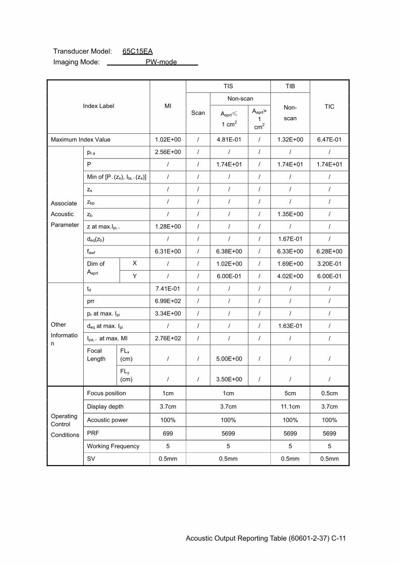
Acoustic Output Reporting Table (60601-2-37) C-11
Transducer Model: 65C15EA Imaging Mode: PW-mode
Index Label MI
TIS TIB
TIC Scan
Non-scan Non-
scan Aaprt≤
1 cm2
Aaprt>1
cm2
Maximum Index Value 1.02E+00 / 4.81E-01 / 1.32E+00 6.47E-01
Associate
Acoustic
Parameter
pr.a 2.56E+00 / / / / /
P / / 1.74E+01 / 1.74E+01 1.74E+01
Min of [Pα(zs), Ita,α(zs)] / / / / / /
zs / / / / / /
zbp / / / / / /
zb / / / / 1.35E+00 /
z at max.Ipi,α 1.28E+00 / / / / /
deq(zb) / / / / 1.67E-01 /
fawf 6.31E+00 / 6.38E+00 / 6.33E+00 6.28E+00
Dim of Aaprt
X / / 1.02E+00 / 1.69E+00 3.20E-01
Y / / 6.00E-01 / 4.02E+00 6.00E-01
Other
Information
td 7.41E-01 / / / / /
prr 6.99E+02 / / / / /
pr at max. Ipi 3.34E+00 / / / / /
deq at max. Ipi / / / / 1.63E-01 /
Ipa,α at max. MI 2.76E+02 / / / / /
Focal Length
FLx (cm) / / 5.00E+00 / / /
FLy (cm) / / 3.50E+00 / / /
Operating Control
Conditions
Focus position 1cm 1cm 5cm 0.5cm
Display depth 3.7cm 3.7cm 11.1cm 3.7cm
Acoustic power 100% 100% 100% 100%
PRF 699 5699 5699 5699
Working Frequency 5 5 5 5
SV 0.5mm 0.5mm 0.5mm 0.5mm
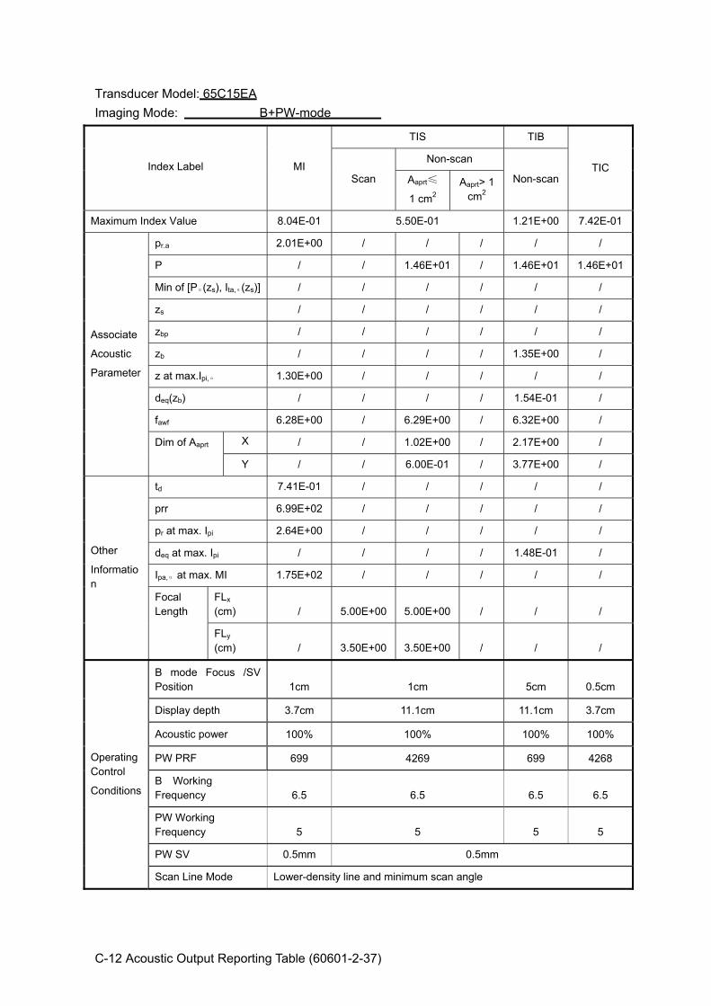
C-12 Acoustic Output Reporting Table (60601-2-37)
Transducer Model: 65C15EA Imaging Mode: B+PW-mode
Index Label MI
TIS TIB
TIC Scan
Non-scan
Non-scan Aaprt≤
1 cm2 Aaprt> 1
cm2
Maximum Index Value 8.04E-01 5.50E-01 1.21E+00 7.42E-01
Associate
Acoustic
Parameter
pr.a 2.01E+00 / / / / /
P / / 1.46E+01 / 1.46E+01 1.46E+01
Min of [Pα(zs), Ita,α(zs)] / / / / / /
zs / / / / / /
zbp / / / / / /
zb / / / / 1.35E+00 /
z at max.Ipi,α 1.30E+00 / / / / /
deq(zb) / / / / 1.54E-01 /
fawf 6.28E+00 / 6.29E+00 / 6.32E+00 /
Dim of Aaprt X / / 1.02E+00 / 2.17E+00 /
Y / / 6.00E-01 / 3.77E+00 /
Other
Information
td 7.41E-01 / / / / /
prr 6.99E+02 / / / / /
pr at max. Ipi 2.64E+00 / / / / /
deq at max. Ipi / / / / 1.48E-01 /
Ipa,α at max. MI 1.75E+02 / / / / /
Focal Length
FLx (cm) / 5.00E+00 5.00E+00 / / /
FLy (cm) / 3.50E+00 3.50E+00 / / /
Operating Control
Conditions
B mode Focus /SV Position 1cm 1cm 5cm 0.5cm
Display depth 3.7cm 11.1cm 11.1cm 3.7cm
Acoustic power 100% 100% 100% 100%
PW PRF 699 4269 699 4268
B Working Frequency 6.5 6.5 6.5 6.5
PW Working Frequency 5 5 5 5
PW SV 0.5mm 0.5mm
Scan Line Mode Lower-density line and minimum scan angle
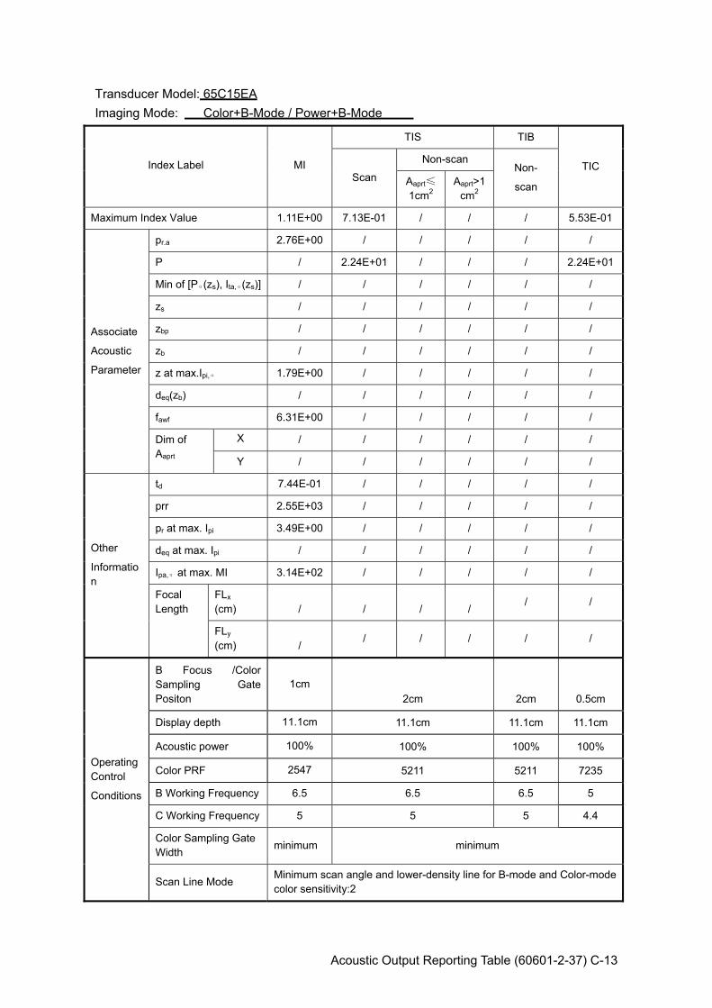
Acoustic Output Reporting Table (60601-2-37) C-13
Transducer Model: 65C15EA Imaging Mode: Color+B-Mode / Power+B-Mode
Index Label MI
TIS TIB
TIC Scan
Non-scan Non-
scan Aaprt≤
1cm2 Aaprt>1
cm2
Maximum Index Value 1.11E+00 7.13E-01 / / / 5.53E-01
Associate
Acoustic
Parameter
pr.a 2.76E+00 / / / / /
P / 2.24E+01 / / / 2.24E+01
Min of [Pα(zs), Ita,α(zs)] / / / / / /
zs / / / / / /
zbp / / / / / /
zb / / / / / /
z at max.Ipi,α 1.79E+00 / / / / /
deq(zb) / / / / / /
fawf 6.31E+00 / / / / /
Dim of Aaprt
X / / / / / /
Y / / / / / /
Other
Information
td 7.44E-01 / / / / /
prr 2.55E+03 / / / / /
pr at max. Ipi 3.49E+00 / / / / /
deq at max. Ipi / / / / / /
Ipa,α at max. MI 3.14E+02 / / / / /
Focal Length
FLx (cm) / / / /
/ /
FLy (cm) /
/ / / / /
Operating Control
Conditions
B Focus /Color Sampling Gate Positon
1cm 2cm 2cm 0.5cm
Display depth 11.1cm 11.1cm 11.1cm 11.1cm
Acoustic power 100% 100% 100% 100%
Color PRF 2547 5211 5211 7235
B Working Frequency 6.5 6.5 6.5 5
C Working Frequency 5 5 5 4.4
Color Sampling Gate Width minimum minimum
Scan Line Mode Minimum scan angle and lower-density line for B-mode and Color-mode color sensitivity:2
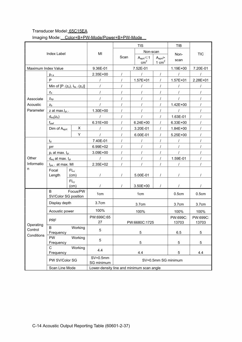
C-14 Acoustic Output Reporting Table (60601-2-37)
Transducer Model: 65C15EA Imaging Mode: Color+B+PW-Mode/Power+B+PW-Mode
Index Label MI
TIS TIB
TIC Scan
Non-scan Non- scan Aaprt≤1
cm2 Aaprt>1 cm2
Maximum Index Value 9.36E-01 7.52E-01 1.19E+00 7.20E-01
Associate Acoustic Parameter
pr.a 2.35E+00 / / / / / P / / 1.57E+01 / 1.57E+01 2.28E+01Min of [Pα(zs), Ita,α(zs)] / / / / / / zs / / / / / / zbp / / / / / / zb / / / / 1.42E+00 / z at max.Ipi,α 1.30E+00 / / / / / deq(zb) / / / / 1.63E-01 / fawf 6.31E+00 / 6.24E+00 / 6.33E+00 / Dim of Aaprt X / / 3.20E-01 / 1.84E+00 /
Y / / 6.00E-01 / 5.25E+00 /
Other Information
td 7.40E-01 / / / / / prr 6.99E+02 / / / / / pr at max. Ipi 3.09E+00 / / / / / deq at max. Ipi / / / / 1.59E-01 / Ipa,α at max. MI 2.35E+02 / / / / / Focal Length
FLx (cm) / / 5.00E-01 / / / FLy (cm) / / 3.50E+00 / / /
Operating Control Conditions
B Focus/PW SV/Color SG position
1cm 1cm 0.5cm 0.5cm
Display depth 3.7cm 3.7cm 3.7cm 3.7cm
Acoustic power 100% 100% 100% 100%
PRF PW:699C:65
27 PW:6680C:1725 PW:699C:
13703 PW:699C:
13703 B Working Frequency
5 5 6.5 5 PW Working Frequency
5 5 5 5
C Working Frequency
4.4 4.4 5 4.4
PW SV/Color SG SV=0.5mm
SG minimumSV=0.5mm SG minimum
Scan Line Mode Lower-density line and minimum scan angle
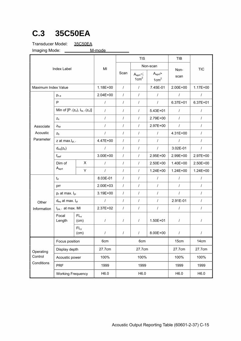
Acoustic Output Reporting Table (60601-2-37) C-15
C.3 35C50EA Transducer Model: 35C50EA Imaging Mode: M-mode
Index Label MI
TIS TIB
TIC Scan
Non-scan Non-
scan Aaprt≤
1cm2 Aaprt>
1cm2
Maximum Index Value 1.18E+00 / / 7.45E-01 2.00E+00 1.17E+00
Associate
Acoustic
Parameter
pr.a 2.04E+00 / / / / /
P / / / / 6.37E+01 6.37E+01
Min of [Pα(zs), Ita,α(zs)] / / / 5.43E+01 / /
zs / / / 2.79E+00 / /
zbp / / / 2.97E+00 / /
zb / / / / 4.31E+00 /
z at max.Ipi,α 4.47E+00 / / / / /
deq(zb) / / / / 3.02E-01 /
fawf 3.00E+00 / / 2.95E+00 2.99E+00 2.97E+00
Dim of Aaprt
X / / / 2.50E+00 1.40E+00 2.50E+00
Y / / / 1.24E+00 1.24E+00 1.24E+00
Other
Information
td 8.03E-01 / / / / /
prr 2.00E+03 / / / / /
pr at max. Ipi 3.19E+00 / / / / /
deq at max. Ipi / / / / 2.91E-01 /
Ipa,α at max. MI 2.37E+02 / / / / /
Focal Length
FLx (cm) / / / 1.50E+01 / /
FLy (cm) / / / 8.00E+00 / /
Operating Control
Conditions
Focus position 6cm 6cm 15cm 14cm
Display depth 27.7cm 27.7cm 27.7cm 27.7cm
Acoustic power 100% 100% 100% 100%
PRF 1999 1999 1999 1999
Working Frequency H6.0 H6.0 H6.0 H6.0
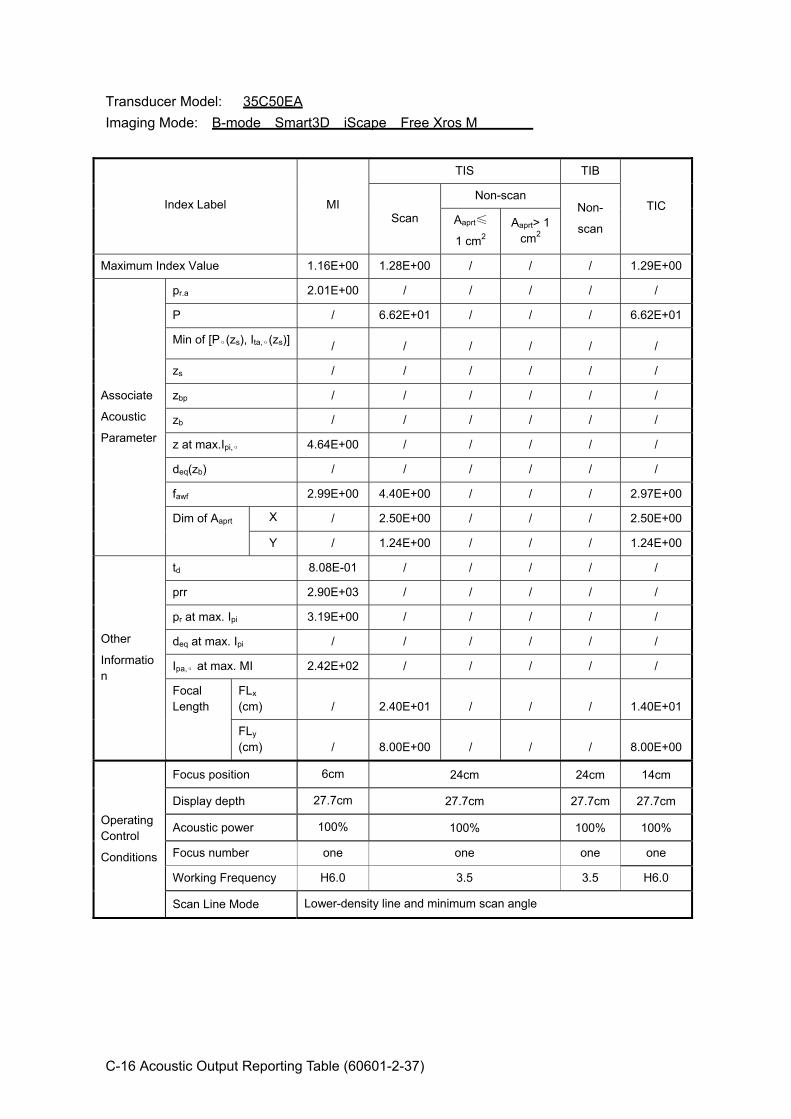
C-16 Acoustic Output Reporting Table (60601-2-37)
Transducer Model: 35C50EA Imaging Mode: B-mode Smart3D iScape Free Xros M
Index Label MI
TIS TIB
TIC Scan
Non-scan Non-
scan Aaprt≤
1 cm2 Aaprt> 1
cm2
Maximum Index Value 1.16E+00 1.28E+00 / / / 1.29E+00
Associate
Acoustic
Parameter
pr.a 2.01E+00 / / / / /
P / 6.62E+01 / / / 6.62E+01
Min of [Pα(zs), Ita,α(zs)] / / / / / /
zs / / / / / /
zbp / / / / / /
zb / / / / / /
z at max.Ipi,α 4.64E+00 / / / / /
deq(zb) / / / / / /
fawf 2.99E+00 4.40E+00 / / / 2.97E+00
Dim of Aaprt X / 2.50E+00 / / / 2.50E+00
Y / 1.24E+00 / / / 1.24E+00
Other
Information
td 8.08E-01 / / / / /
prr 2.90E+03 / / / / /
pr at max. Ipi 3.19E+00 / / / / /
deq at max. Ipi / / / / / /
Ipa,α at max. MI 2.42E+02 / / / / /
Focal Length
FLx (cm) / 2.40E+01 / / / 1.40E+01
FLy (cm) / 8.00E+00 / / / 8.00E+00
Operating Control
Conditions
Focus position 6cm 24cm 24cm 14cm
Display depth 27.7cm 27.7cm 27.7cm 27.7cm
Acoustic power 100% 100% 100% 100%
Focus number one one one one
Working Frequency H6.0 3.5 3.5 H6.0
Scan Line Mode Lower-density line and minimum scan angle
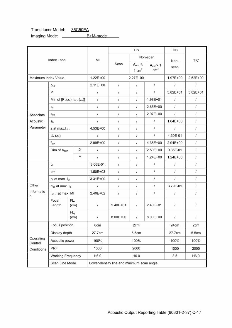
Acoustic Output Reporting Table (60601-2-37) C-17
Transducer Model: 35C50EA Imaging Mode: B+M-mode
Index Label MI
TIS TIB
TIC Scan
Non-scan Non-
scan Aaprt≤
1 cm2 Aaprt> 1
cm2
Maximum Index Value 1.22E+00 2.27E+00 1.97E+00 2.52E+00
Associate
Acoustic
Parameter
pr.a 2.11E+00 / / / / /
P / / / / 3.82E+01 3.82E+01
Min of [Pα(zs), Ita,α(zs)] / / / 1.98E+01 / /
zs / / / 2.65E+00 / /
zbp / / / 2.97E+00 / /
zb / / / / 1.64E+00 /
z at max.Ipi,α 4.53E+00 / / / / /
deq(zb) / / / / 4.30E-01 /
fawf 2.99E+00 / / 4.38E+00 2.94E+00 /
Dim of Aaprt X / / / 2.50E+00 9.36E-01 /
Y / / / 1.24E+00 1.24E+00 /
Other
Information
td 8.06E-01 / / / / /
prr 1.50E+03 / / / / /
pr at max. Ipi 3.31E+00 / / / / /
deq at max. Ipi / / / / 3.79E-01 /
Ipa,α at max. MI 2.40E+02 / / / / /
Focal Length
FLx (cm) / 2.40E+01 / 2.40E+01 / /
FLy (cm) / 8.00E+00 / 8.00E+00 / /
Operating Control
Conditions
Focus position 6cm 2cm 24cm 2cm
Display depth 27.7cm 5.5cm 27.7cm 5.5cm
Acoustic power 100% 100% 100% 100%
PRF 1000 2000 1000 2000
Working Frequency H6.0 H6.0 3.5 H6.0
Scan Line Mode Lower-density line and minimum scan angle
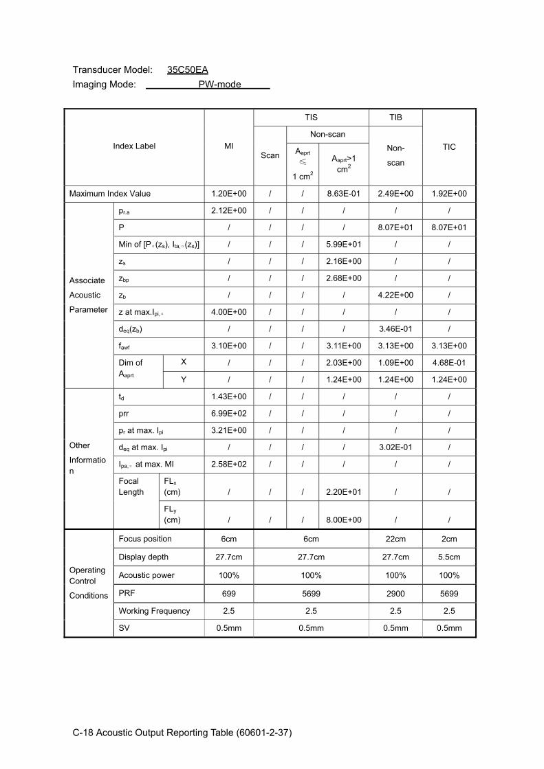
C-18 Acoustic Output Reporting Table (60601-2-37)
Transducer Model: 35C50EA Imaging Mode: PW-mode
Index Label MI
TIS TIB
TIC Scan
Non-scan
Non-
scan Aaprt
≤
1 cm2
Aaprt>1 cm2
Maximum Index Value 1.20E+00 / / 8.63E-01 2.49E+00 1.92E+00
Associate
Acoustic
Parameter
pr.a 2.12E+00 / / / / /
P / / / / 8.07E+01 8.07E+01
Min of [Pα(zs), Ita,α(zs)] / / / 5.99E+01 / /
zs / / / 2.16E+00 / /
zbp / / / 2.68E+00 / /
zb / / / / 4.22E+00 /
z at max.Ipi,α 4.00E+00 / / / / /
deq(zb) / / / / 3.46E-01 /
fawf 3.10E+00 / / 3.11E+00 3.13E+00 3.13E+00
Dim of Aaprt
X / / / 2.03E+00 1.09E+00 4.68E-01
Y / / / 1.24E+00 1.24E+00 1.24E+00
Other
Information
td 1.43E+00 / / / / /
prr 6.99E+02 / / / / /
pr at max. Ipi 3.21E+00 / / / / /
deq at max. Ipi / / / / 3.02E-01 /
Ipa,α at max. MI 2.58E+02 / / / / /
Focal Length
FLx (cm) / / / 2.20E+01 / /
FLy (cm) / / / 8.00E+00 / /
Operating Control
Conditions
Focus position 6cm 6cm 22cm 2cm
Display depth 27.7cm 27.7cm 27.7cm 5.5cm
Acoustic power 100% 100% 100% 100%
PRF 699 5699 2900 5699
Working Frequency 2.5 2.5 2.5 2.5
SV 0.5mm 0.5mm 0.5mm 0.5mm
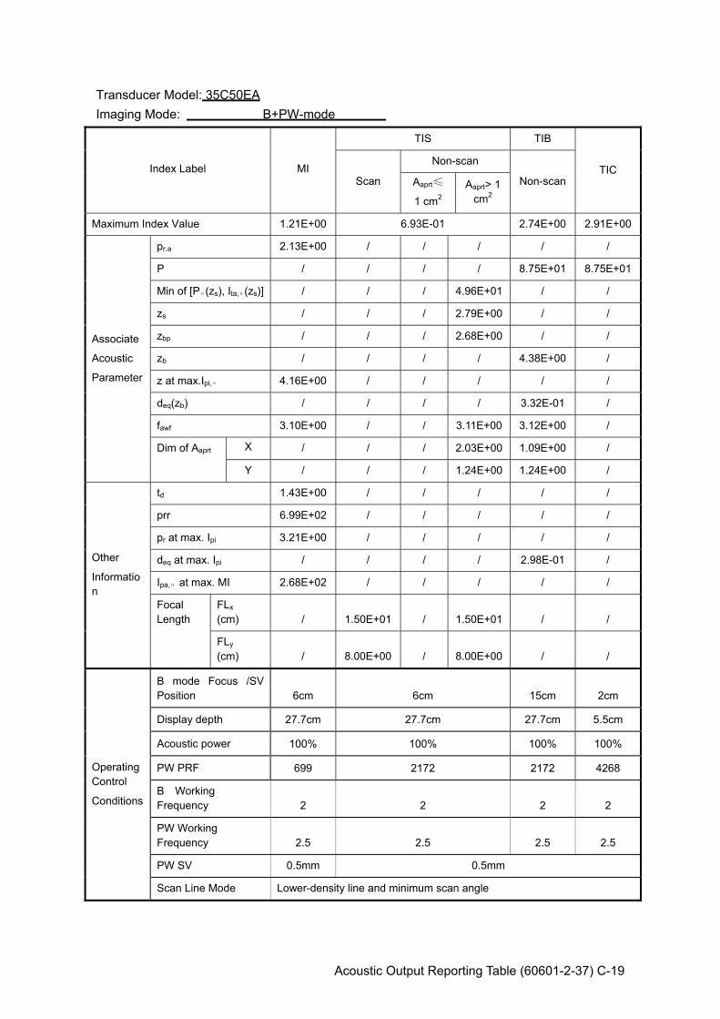
Acoustic Output Reporting Table (60601-2-37) C-19
Transducer Model: 35C50EA Imaging Mode: B+PW-mode
Index Label MI
TIS TIB
TIC Scan
Non-scan
Non-scan Aaprt≤
1 cm2 Aaprt> 1
cm2
Maximum Index Value 1.21E+00 6.93E-01 2.74E+00 2.91E+00
Associate
Acoustic
Parameter
pr.a 2.13E+00 / / / / /
P / / / / 8.75E+01 8.75E+01
Min of [Pα(zs), Ita,α(zs)] / / / 4.96E+01 / /
zs / / / 2.79E+00 / /
zbp / / / 2.68E+00 / /
zb / / / / 4.38E+00 /
z at max.Ipi,α 4.16E+00 / / / / /
deq(zb) / / / / 3.32E-01 /
fawf 3.10E+00 / / 3.11E+00 3.12E+00 /
Dim of Aaprt X / / / 2.03E+00 1.09E+00 /
Y / / / 1.24E+00 1.24E+00 /
Other
Information
td 1.43E+00 / / / / /
prr 6.99E+02 / / / / /
pr at max. Ipi 3.21E+00 / / / / /
deq at max. Ipi / / / / 2.98E-01 /
Ipa,α at max. MI 2.68E+02 / / / / /
Focal Length
FLx (cm) / 1.50E+01 / 1.50E+01 / /
FLy (cm) / 8.00E+00 / 8.00E+00 / /
Operating Control
Conditions
B mode Focus /SV Position 6cm 6cm 15cm 2cm
Display depth 27.7cm 27.7cm 27.7cm 5.5cm
Acoustic power 100% 100% 100% 100%
PW PRF 699 2172 2172 4268
B Working Frequency 2 2 2 2
PW Working Frequency 2.5 2.5 2.5 2.5
PW SV 0.5mm 0.5mm
Scan Line Mode Lower-density line and minimum scan angle
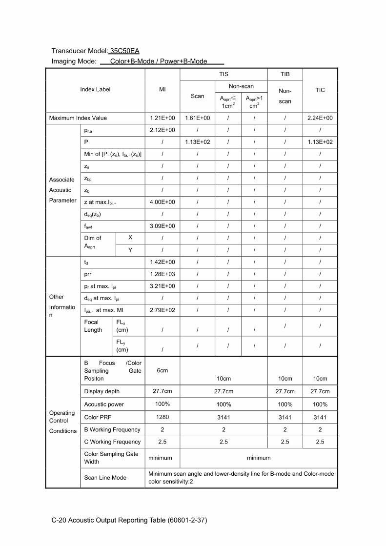
C-20 Acoustic Output Reporting Table (60601-2-37)
Transducer Model: 35C50EA Imaging Mode: Color+B-Mode / Power+B-Mode
Index Label MI
TIS TIB
TIC Scan
Non-scan Non-
scan Aaprt≤
1cm2 Aaprt>1
cm2
Maximum Index Value 1.21E+00 1.61E+00 / / / 2.24E+00
Associate
Acoustic
Parameter
pr.a 2.12E+00 / / / / /
P / 1.13E+02 / / / 1.13E+02
Min of [Pα(zs), Ita,α(zs)] / / / / / /
zs / / / / / /
zbp / / / / / /
zb / / / / / /
z at max.Ipi,α 4.00E+00 / / / / /
deq(zb) / / / / / /
fawf 3.09E+00 / / / / /
Dim of Aaprt
X / / / / / /
Y / / / / / /
Other
Information
td 1.42E+00 / / / / /
prr 1.28E+03 / / / / /
pr at max. Ipi 3.21E+00 / / / / /
deq at max. Ipi / / / / / /
Ipa,α at max. MI 2.79E+02 / / / / /
Focal Length
FLx (cm) / / / /
/ /
FLy (cm) /
/ / / / /
Operating Control
Conditions
B Focus /Color Sampling Gate Positon
6cm 10cm 10cm 10cm
Display depth 27.7cm 27.7cm 27.7cm 27.7cm
Acoustic power 100% 100% 100% 100%
Color PRF 1280 3141 3141 3141
B Working Frequency 2 2 2 2
C Working Frequency 2.5 2.5 2.5 2.5
Color Sampling Gate Width minimum minimum
Scan Line Mode Minimum scan angle and lower-density line for B-mode and Color-mode color sensitivity:2
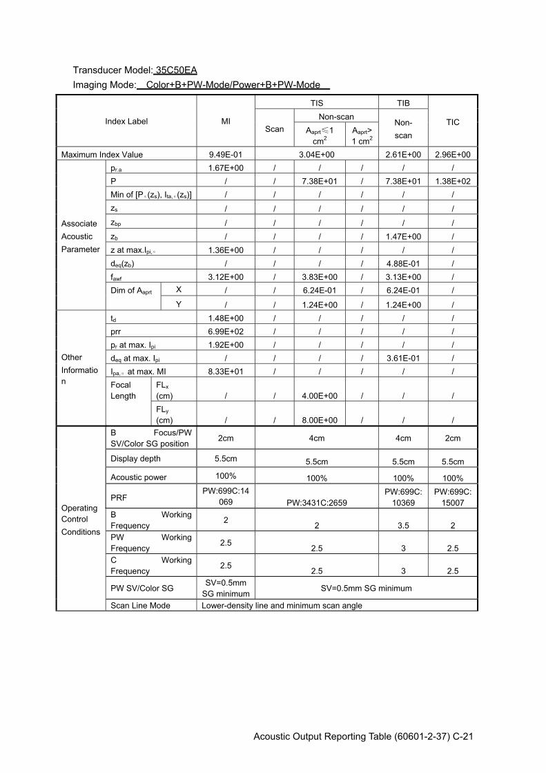
Acoustic Output Reporting Table (60601-2-37) C-21
Transducer Model: 35C50EA Imaging Mode: Color+B+PW-Mode/Power+B+PW-Mode
Index Label MI
TIS TIB
TIC Scan
Non-scan Non- scan Aaprt≤1
cm2 Aaprt>1 cm2
Maximum Index Value 9.49E-01 3.04E+00 2.61E+00 2.96E+00
Associate Acoustic Parameter
pr.a 1.67E+00 / / / / / P / / 7.38E+01 / 7.38E+01 1.38E+02Min of [Pα(zs), Ita,α(zs)] / / / / / / zs / / / / / / zbp / / / / / / zb / / / / 1.47E+00 / z at max.Ipi,α 1.36E+00 / / / / / deq(zb) / / / / 4.88E-01 / fawf 3.12E+00 / 3.83E+00 / 3.13E+00 / Dim of Aaprt X / / 6.24E-01 / 6.24E-01 /
Y / / 1.24E+00 / 1.24E+00 /
Other Information
td 1.48E+00 / / / / / prr 6.99E+02 / / / / / pr at max. Ipi 1.92E+00 / / / / / deq at max. Ipi / / / / 3.61E-01 / Ipa,α at max. MI 8.33E+01 / / / / / Focal Length
FLx (cm) / / 4.00E+00 / / / FLy (cm) / / 8.00E+00 / / /
Operating Control Conditions
B Focus/PW SV/Color SG position
2cm 4cm 4cm 2cm
Display depth 5.5cm 5.5cm 5.5cm 5.5cm
Acoustic power 100% 100% 100% 100%
PRF PW:699C:14
069 PW:3431C:2659 PW:699C:
10369 PW:699C:
15007 B Working Frequency
2 2 3.5 2 PW Working Frequency
2.5 2.5 3 2.5
C Working Frequency
2.5 2.5 3 2.5
PW SV/Color SG SV=0.5mm
SG minimumSV=0.5mm SG minimum
Scan Line Mode Lower-density line and minimum scan angle
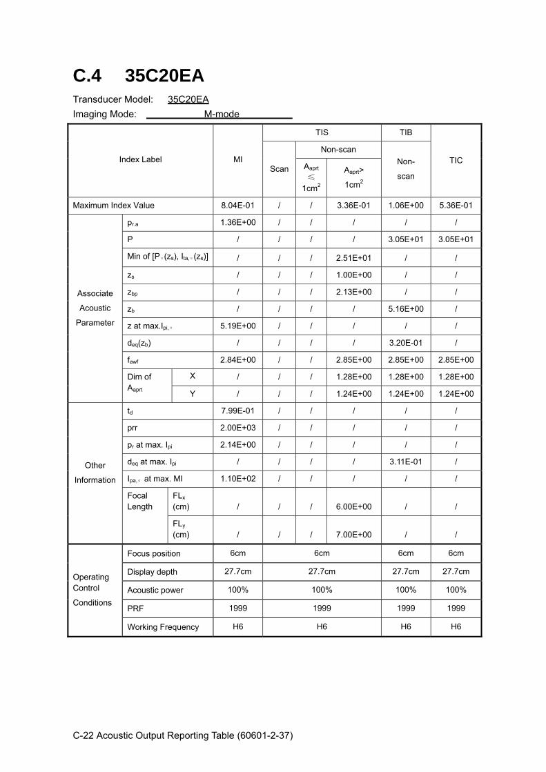
C-22 Acoustic Output Reporting Table (60601-2-37)
C.4 35C20EA Transducer Model: 35C20EA Imaging Mode: M-mode
Index Label MI
TIS TIB
TIC Scan
Non-scan Non-
scan Aaprt
≤
1cm2
Aaprt>
1cm2
Maximum Index Value 8.04E-01 / / 3.36E-01 1.06E+00 5.36E-01
Associate
Acoustic
Parameter
pr.a 1.36E+00 / / / / /
P / / / / 3.05E+01 3.05E+01
Min of [Pα(zs), Ita,α(zs)] / / / 2.51E+01 / /
zs / / / 1.00E+00 / /
zbp / / / 2.13E+00 / /
zb / / / / 5.16E+00 /
z at max.Ipi,α 5.19E+00 / / / / /
deq(zb) / / / / 3.20E-01 /
fawf 2.84E+00 / / 2.85E+00 2.85E+00 2.85E+00
Dim of Aaprt
X / / / 1.28E+00 1.28E+00 1.28E+00
Y / / / 1.24E+00 1.24E+00 1.24E+00
Other
Information
td 7.99E-01 / / / / /
prr 2.00E+03 / / / / /
pr at max. Ipi 2.14E+00 / / / / /
deq at max. Ipi / / / / 3.11E-01 /
Ipa,α at max. MI 1.10E+02 / / / / /
Focal Length
FLx (cm) / / / 6.00E+00 / /
FLy (cm) / / / 7.00E+00 / /
Operating Control
Conditions
Focus position 6cm 6cm 6cm 6cm
Display depth 27.7cm 27.7cm 27.7cm 27.7cm
Acoustic power 100% 100% 100% 100%
PRF 1999 1999 1999 1999
Working Frequency H6 H6 H6 H6

Acoustic Output Reporting Table (60601-2-37) C-23
Transducer Model: 35C20EA Imaging Mode: B-mode Smart3D iScape Free Xros M
Index Label MI
TIS TIB
TIC Scan
Non-scan Non-
scan Aaprt≤
1 cm2 Aaprt> 1
cm2
Maximum Index Value 9.51E-01 4.48E-01 / / / 4.79E-01
Associate
Acoustic
Parameter
pr.a 1.57E+00 / / / / /
P / 2.43E+01 / / / 2.43E+01
Min of [Pα(zs), Ita,α(zs)] / / / / / /
zs / / / / / /
zbp / / / / / /
zb / / / / / /
z at max.Ipi,α 5.27E+00 / / / / /
deq(zb) / / / / / /
fawf 2.85E+00 3.91E+00 / / / 3.91E+00
Dim of Aaprt X / 1.28E+00 / / / 1.28E+00
Y / 1.24E+00 / / / 1.24E+00
Other
Information
td 8.00E-01 / / / / /
prr 2.91E+03 / / / / /
pr at max. Ipi 2.28E+00 / / / / /
deq at max. Ipi / / / / / /
Ipa,α at max. MI 1.11E+02 / / / / /
Focal Length
FLx (cm) / 6.00E+00 / / / 6.00E+00
FLy (cm) / 7.00E+00 / / / 7.00E+00
Operating Control
Conditions
Focus position 6cm 6cm 6cm 6cm
Display depth 27.7cm 27.7cm 27.7cm 27.7cm
Acoustic power 100% 100% 100% 100%
Focus number one one one one
Working Frequency H6 3.5 3.5 3.5
Scan Line Mode Lower-density line and minimum scan angle
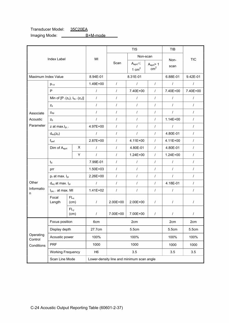
C-24 Acoustic Output Reporting Table (60601-2-37)
Transducer Model: 35C20EA Imaging Mode: B+M-mode
Index Label MI
TIS TIB
TIC Scan
Non-scan Non-
scan Aaprt≤
1 cm2 Aaprt> 1
cm2
Maximum Index Value 8.94E-01 8.31E-01 6.88E-01 9.42E-01
Associate
Acoustic
Parameter
pr.a 1.49E+00 / / / / /
P / / 7.40E+00 / 7.40E+00 7.40E+00
Min of [Pα(zs), Ita,α(zs)] / / / / / /
zs / / / / / /
zbp / / / / / /
zb / / / / 1.14E+00 /
z at max.Ipi,α 4.97E+00 / / / / /
deq(zb) / / / / 4.80E-01 /
fawf 2.87E+00 / 4.11E+00 / 4.11E+00 /
Dim of Aaprt X / / 4.80E-01 / 4.80E-01 /
Y / / 1.24E+00 / 1.24E+00 /
Other
Information
td 7.99E-01 / / / / /
prr 1.50E+03 / / / / /
pr at max. Ipi 2.26E+00 / / / / /
deq at max. Ipi / / / / 4.18E-01 /
Ipa,α at max. MI 1.41E+02 / / / / /
Focal Length
FLx (cm) / 2.00E+00 2.00E+00 / / /
FLy (cm) / 7.00E+00 7.00E+00 / / /
Operating Control
Conditions
Focus position 6cm 2cm 2cm 2cm
Display depth 27.7cm 5.5cm 5.5cm 5.5cm
Acoustic power 100% 100% 100% 100%
PRF 1000 1000 1000 1000
Working Frequency H6 3.5 3.5 3.5
Scan Line Mode Lower-density line and minimum scan angle
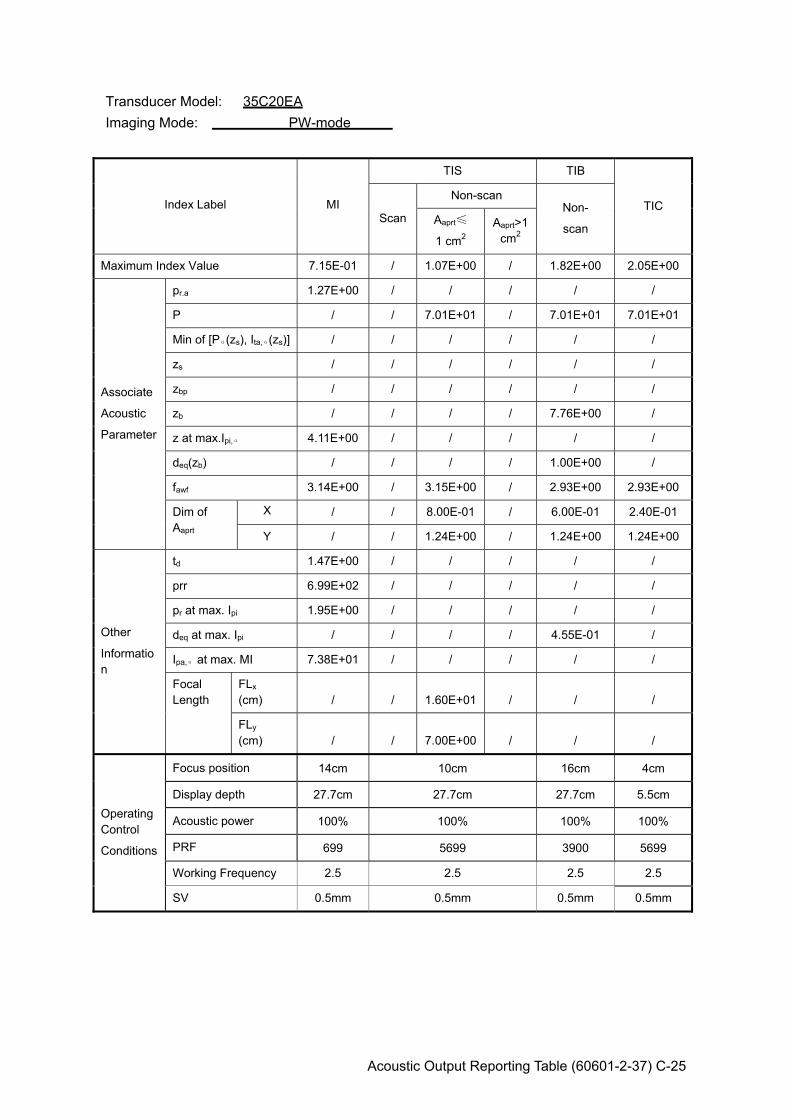
Acoustic Output Reporting Table (60601-2-37) C-25
Transducer Model: 35C20EA Imaging Mode: PW-mode
Index Label MI
TIS TIB
TIC Scan
Non-scan Non-
scan Aaprt≤
1 cm2 Aaprt>1
cm2
Maximum Index Value 7.15E-01 / 1.07E+00 / 1.82E+00 2.05E+00
Associate
Acoustic
Parameter
pr.a 1.27E+00 / / / / /
P / / 7.01E+01 / 7.01E+01 7.01E+01
Min of [Pα(zs), Ita,α(zs)] / / / / / /
zs / / / / / /
zbp / / / / / /
zb / / / / 7.76E+00 /
z at max.Ipi,α 4.11E+00 / / / / /
deq(zb) / / / / 1.00E+00 /
fawf 3.14E+00 / 3.15E+00 / 2.93E+00 2.93E+00
Dim of Aaprt
X / / 8.00E-01 / 6.00E-01 2.40E-01
Y / / 1.24E+00 / 1.24E+00 1.24E+00
Other
Information
td 1.47E+00 / / / / /
prr 6.99E+02 / / / / /
pr at max. Ipi 1.95E+00 / / / / /
deq at max. Ipi / / / / 4.55E-01 /
Ipa,α at max. MI 7.38E+01 / / / / /
Focal Length
FLx (cm) / / 1.60E+01 / / /
FLy (cm) / / 7.00E+00 / / /
Operating Control
Conditions
Focus position 14cm 10cm 16cm 4cm
Display depth 27.7cm 27.7cm 27.7cm 5.5cm
Acoustic power 100% 100% 100% 100%
PRF 699 5699 3900 5699
Working Frequency 2.5 2.5 2.5 2.5
SV 0.5mm 0.5mm 0.5mm 0.5mm
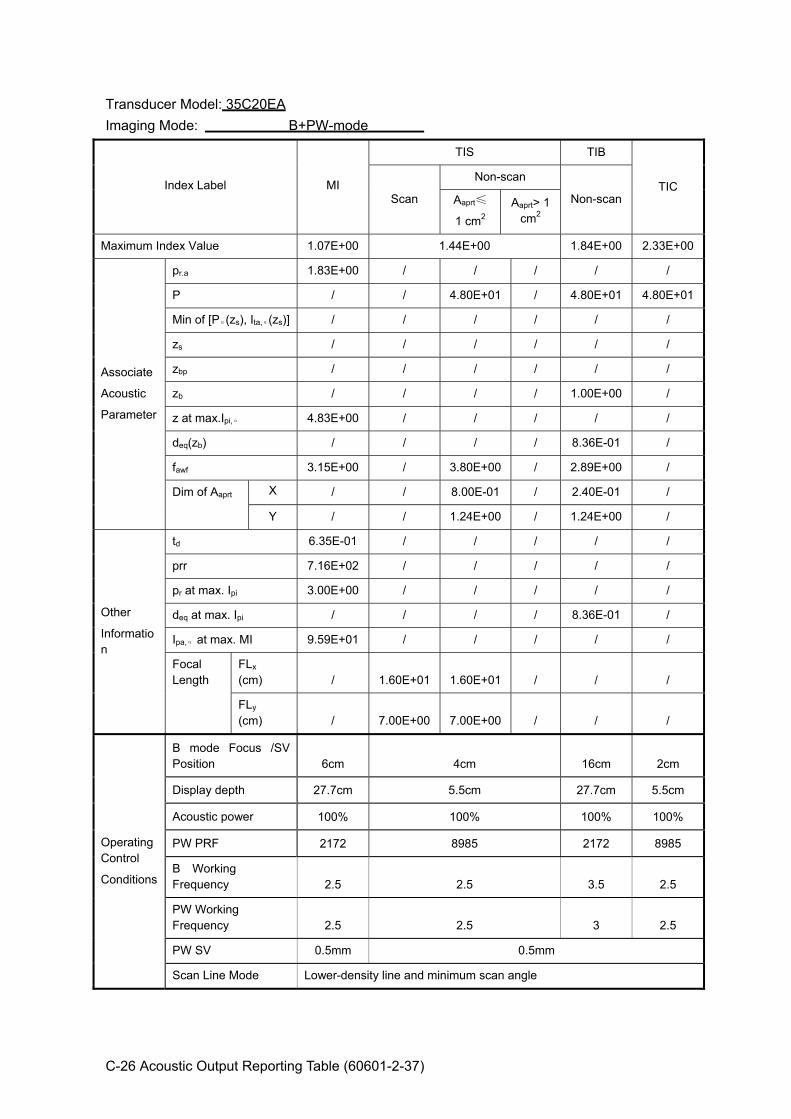
C-26 Acoustic Output Reporting Table (60601-2-37)
Transducer Model: 35C20EA Imaging Mode: B+PW-mode
Index Label MI
TIS TIB
TIC Scan
Non-scan
Non-scan Aaprt≤
1 cm2 Aaprt> 1
cm2
Maximum Index Value 1.07E+00 1.44E+00 1.84E+00 2.33E+00
Associate
Acoustic
Parameter
pr.a 1.83E+00 / / / / /
P / / 4.80E+01 / 4.80E+01 4.80E+01
Min of [Pα(zs), Ita,α(zs)] / / / / / /
zs / / / / / /
zbp / / / / / /
zb / / / / 1.00E+00 /
z at max.Ipi,α 4.83E+00 / / / / /
deq(zb) / / / / 8.36E-01 /
fawf 3.15E+00 / 3.80E+00 / 2.89E+00 /
Dim of Aaprt X / / 8.00E-01 / 2.40E-01 /
Y / / 1.24E+00 / 1.24E+00 /
Other
Information
td 6.35E-01 / / / / /
prr 7.16E+02 / / / / /
pr at max. Ipi 3.00E+00 / / / / /
deq at max. Ipi / / / / 8.36E-01 /
Ipa,α at max. MI 9.59E+01 / / / / /
Focal Length
FLx (cm) / 1.60E+01 1.60E+01 / / /
FLy (cm) / 7.00E+00 7.00E+00 / / /
Operating Control
Conditions
B mode Focus /SV Position 6cm 4cm 16cm 2cm
Display depth 27.7cm 5.5cm 27.7cm 5.5cm
Acoustic power 100% 100% 100% 100%
PW PRF 2172 8985 2172 8985
B Working Frequency 2.5 2.5 3.5 2.5
PW Working Frequency 2.5 2.5 3 2.5
PW SV 0.5mm 0.5mm
Scan Line Mode Lower-density line and minimum scan angle

Acoustic Output Reporting Table (60601-2-37) C-27
Transducer Model: 35C20EA Imaging Mode: Color+B-Mode / Power+B-Mode
Index Label MI
TIS TIB
TIC Scan
Non-scan Non-
scan Aaprt≤
1cm2 Aaprt>1
cm2
Maximum Index Value 8.02E-01 1.18E+00 / / / 1.39E+00
Associate
Acoustic
Parameter
pr.a 1.42E+00 / / / / /
P / 6.80E+01 / / / 6.80E+01
Min of [Pα(zs), Ita,α(zs)] / / / / / /
zs / / / / / /
zbp / / / / / /
zb / / / / / /
z at max.Ipi,α 4.43E+00 / / / / /
deq(zb) / / / / / /
fawf 3.12E+00 / / / / /
Dim of Aaprt
X / / / / / /
Y / / / / / /
Other
Information
td 1.46E+00 / / / / /
prr 7.37E+02 / / / / /
pr at max. Ipi 2.25E+00 / / / / /
deq at max. Ipi / / / / / /
Ipa,α at max. MI 1.17E+02 / / / / /
Focal Length
FLx (cm) / / / /
/ /
FLy (cm) /
/ / / / /
Operating Control
Conditions
B Focus /Color Sampling Gate Positon
8cm 10cm 10cm 10cm
Display depth 27.7cm 27.7cm 27.7cm 27.7cm
Acoustic power 100% 100% 100% 100%
Color PRF 737 2918 2918 2918
B Working Frequency 2.5 3.5 3.5 3.5
C Working Frequency 2.5 3 3 3
Color Sampling Gate Width minimum minimum
Scan Line Mode Minimum scan angle and lower-density line for B-mode and Color-mode color sensitivity:2
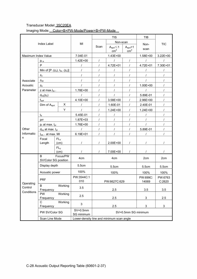
C-28 Acoustic Output Reporting Table (60601-2-37)
Transducer Model: 35C20EA Imaging Mode: Color+B+PW-Mode/Power+B+PW-Mode
Index Label MI
TIS TIB
TIC Scan
Non-scan Non- scan Aaprt≤1
cm2 Aaprt>1
cm2 Maximum Index Value 7.04E-01 1.43E+00 1.58E+00 3.22E+00
Associate Acoustic Parameter
pr.a 1.42E+00 / / / / / P / / 4.72E+01 / 4.72E+01 7.30E+01Min of [Pα(zs), Ita,α(zs)] / / / / / / zs / / / / / / zbp / / / / / / zb / / / / 1.00E+00 / z at max.Ipi,α 1.78E+00 / / / / / deq(zb) / / / / 5.89E-01 / fawf 4.10E+00 / 3.58E+00 / 2.96E+00 / Dim of Aaprt X / / 1.60E-01 / 2.40E-01 /
Y / / 1.24E+00 / 1.24E+00 /
Other Information
td 5.45E-01 / / / / / prr 1.87E+03 / / / / / pr at max. Ipi 1.76E+00 / / / / / deq at max. Ipi / / / / 5.89E-01 / Ipa,α at max. MI 6.19E+01 / / / / / Focal Length
FLx (cm) / / 2.00E+00 / / / FLy (cm) / / 7.00E+00 / / /
Operating Control Conditions
B Focus/PW SV/Color SG position
4cm 4cm 2cm 2cm
Display depth 5.5cm 5.5cm 5.5cm 5.5cm
Acoustic power 100% 100% 100% 100%
PRF PW:3544C:1
010 PW:6627C:629 PW:699C:
14069 PW:6763C:2620
B Working Frequency
3.5 2.5 3.5 3.5 PW Working Frequency
2.5 2.5 3 2.5
C Working Frequency
3 2.5 3 3
PW SV/Color SG SV=0.5mm
SG minimumSV=0.5mm SG minimum
Scan Line Mode Lower-density line and minimum scan angle
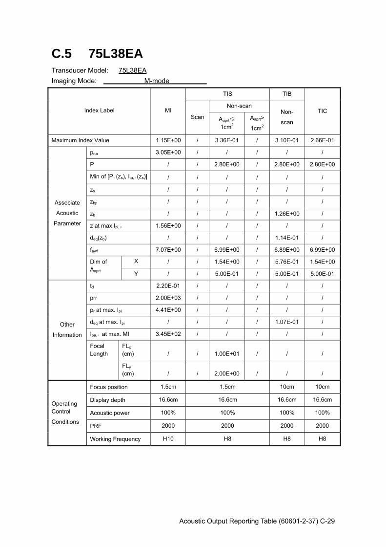
Acoustic Output Reporting Table (60601-2-37) C-29
C.5 75L38EA Transducer Model: 75L38EA Imaging Mode: M-mode
Index Label MI
TIS TIB
TIC Scan
Non-scan Non-
scan Aaprt≤
1cm2 Aaprt>
1cm2
Maximum Index Value 1.15E+00 / 3.36E-01 / 3.10E-01 2.66E-01
Associate
Acoustic
Parameter
pr.a 3.05E+00 / / / / /
P / / 2.80E+00 / 2.80E+00 2.80E+00
Min of [Pα(zs), Ita,α(zs)] / / / / / /
zs / / / / / /
zbp / / / / / /
zb / / / / 1.26E+00 /
z at max.Ipi,α 1.56E+00 / / / / /
deq(zb) / / / / 1.14E-01 /
fawf 7.07E+00 / 6.99E+00 / 6.89E+00 6.99E+00
Dim of Aaprt
X / / 1.54E+00 / 5.76E-01 1.54E+00
Y / / 5.00E-01 / 5.00E-01 5.00E-01
Other
Information
td 2.20E-01 / / / / /
prr 2.00E+03 / / / / /
pr at max. Ipi 4.41E+00 / / / / /
deq at max. Ipi / / / / 1.07E-01 /
Ipa,α at max. MI 3.45E+02 / / / / /
Focal Length
FLx (cm) / / 1.00E+01 / / /
FLy (cm) / / 2.00E+00 / / /
Operating Control
Conditions
Focus position 1.5cm 1.5cm 10cm 10cm
Display depth 16.6cm 16.6cm 16.6cm 16.6cm
Acoustic power 100% 100% 100% 100%
PRF 2000 2000 2000 2000
Working Frequency H10 H8 H8 H8

C-30 Acoustic Output Reporting Table (60601-2-37)
Transducer Model: 75L38EA Imaging Mode: B-mode Smart3D iScape Free Xros M
Index Label MI
TIS TIB
TIC Scan
Non-scan Non-
scan Aaprt≤
1 cm2 Aaprt> 1
cm2
Maximum Index Value 1.41E+00 4.69E-01 / / / 4.39E-01
Associate
Acoustic
Parameter
pr.a 3.78E+00 / / / / /
P / 1.45E+01 / / / 1.45E+01
Min of [Pα(zs), Ita,α(zs)] / / / / / /
zs / / / / / /
zbp / / / / / /
zb / / / / / /
z at max.Ipi,α 1.41E+00 / / / / /
deq(zb) / / / / / /
fawf 7.23E+00 6.83E+00 / / / 6.83E+00
Dim of Aaprt X / 1.54E+00 / / / 1.54E+00
Y / 5.00E-01 / / / 5.00E-01
Other
Information
td 2.19E-01 / / / / /
prr 4.11E+03 / / / / /
pr at max. Ipi 5.32E+00 / / / / /
deq at max. Ipi / / / / / /
Ipa,α at max. MI 4.83E+02 / / / / /
Focal Length
FLx (cm) / 1.00E+01 / / / 1.00E+01
FLy (cm) / 2.00E+00 / / / 2.00E+00
Operating Control
Conditions
Focus position 1.5cm 10cm 10cm 10cm
Display depth 16.6cm 16.6cm 16.6cm 16.6cm
Acoustic power 100% 100% 100% 100%
Focus number one one one one
Working Frequency H10 H8 H8 H8
Scan Line Mode Lower-density line and minimum scan angle

Acoustic Output Reporting Table (60601-2-37) C-31
Transducer Model: 75L38EA Imaging Mode: B+M-mode
Index Label MI
TIS TIB
TIC Scan
Non-scan Non-
scan Aaprt≤
1 cm2 Aaprt> 1
cm2
Maximum Index Value 1.35E+00 9.96E-01 3.96E-01 6.96E-01
Associate
Acoustic
Parameter
pr.a 3.60E+00 / / / / /
P / / 3.55E+00 / 3.55E+00 3.55E+00
Min of [Pα(zs), Ita,α(zs)] / / / / / /
zs / / / / / /
zbp / / / / / /
zb / / / / 1.35E+00 /
z at max.Ipi,α 1.35E+00 / / / / /
deq(zb) / / / / 1.10E-01 /
fawf 7.14E+00 / 6.81E+00 / 6.96E+00 /
Dim of Aaprt X / / 1.54E+00 / 5.76E-01 /
Y / / 5.00E-01 / 5.00E-01 /
Other
Information
td 2.20E-01 / / / / /
prr 2.00E+03 / / / / /
pr at max. Ipi 4.97E+00 / / / / /
deq at max. Ipi / / / / 1.10E-01 /
Ipa,α at max. MI 3.81E+02 / / / / /
Focal Length
FLx (cm) / 1.00E+01 1.00E+01 / / /
FLy (cm) / 2.00E+00 2.00E+00 / / /
Operating Control
Conditions
Focus position 1.5cm 1.5cm 10cm 10cm
Display depth 16.6cm 16.6cm 16.6cm 16.6cm
Acoustic power 100% 100% 100% 100%
PRF 2000 2000 2000 2000
Working Frequency H10 H8 H8 H8
Scan Line Mode Lower-density line and minimum scan angle
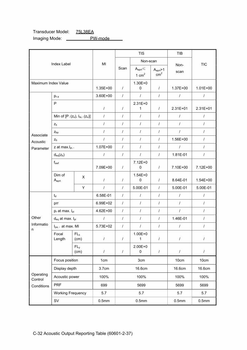
C-32 Acoustic Output Reporting Table (60601-2-37)
Transducer Model: 75L38EA Imaging Mode: PW-mode
Index Label MI
TIS TIB
TIC Scan
Non-scan Non-
scan Aaprt≤
1 cm2 Aaprt>1
cm2
Maximum Index Value 1.35E+00 /
1.30E+00 / 1.37E+00 1.01E+00
Associate
Acoustic
Parameter
pr.a 3.60E+00 / / / / /
P / /
2.31E+01 / 2.31E+01 2.31E+01
Min of [Pα(zs), Ita,α(zs)] / / / / / /
zs / / / / / /
zbp / / / / / /
zb / / / / 1.56E+00 /
z at max.Ipi,α 1.07E+00 / / / / /
deq(zb) / / / / 1.81E-01 /
fawf 7.09E+00 /
7.12E+00 / 7.10E+00 7.12E+00
Dim of Aaprt
X / /
1.54E+00 / 8.64E-01 1.54E+00
Y / / 5.00E-01 / 5.00E-01 5.00E-01
Other
Information
td 6.58E-01 / / / / /
prr 6.99E+02 / / / / /
pr at max. Ipi 4.62E+00 / / / / /
deq at max. Ipi / / / / 1.46E-01 /
Ipa,α at max. MI 5.73E+02 / / / / /
Focal Length
FLx (cm) / /
1.00E+01 / / /
FLy (cm) / /
2.00E+00 / / /
Operating Control
Conditions
Focus position 1cm 3cm 10cm 10cm
Display depth 3.7cm 16.6cm 16.6cm 16.6cm
Acoustic power 100% 100% 100% 100%
PRF 699 5699 5699 5699
Working Frequency 5.7 5.7 5.7 5.7
SV 0.5mm 0.5mm 0.5mm 0.5mm
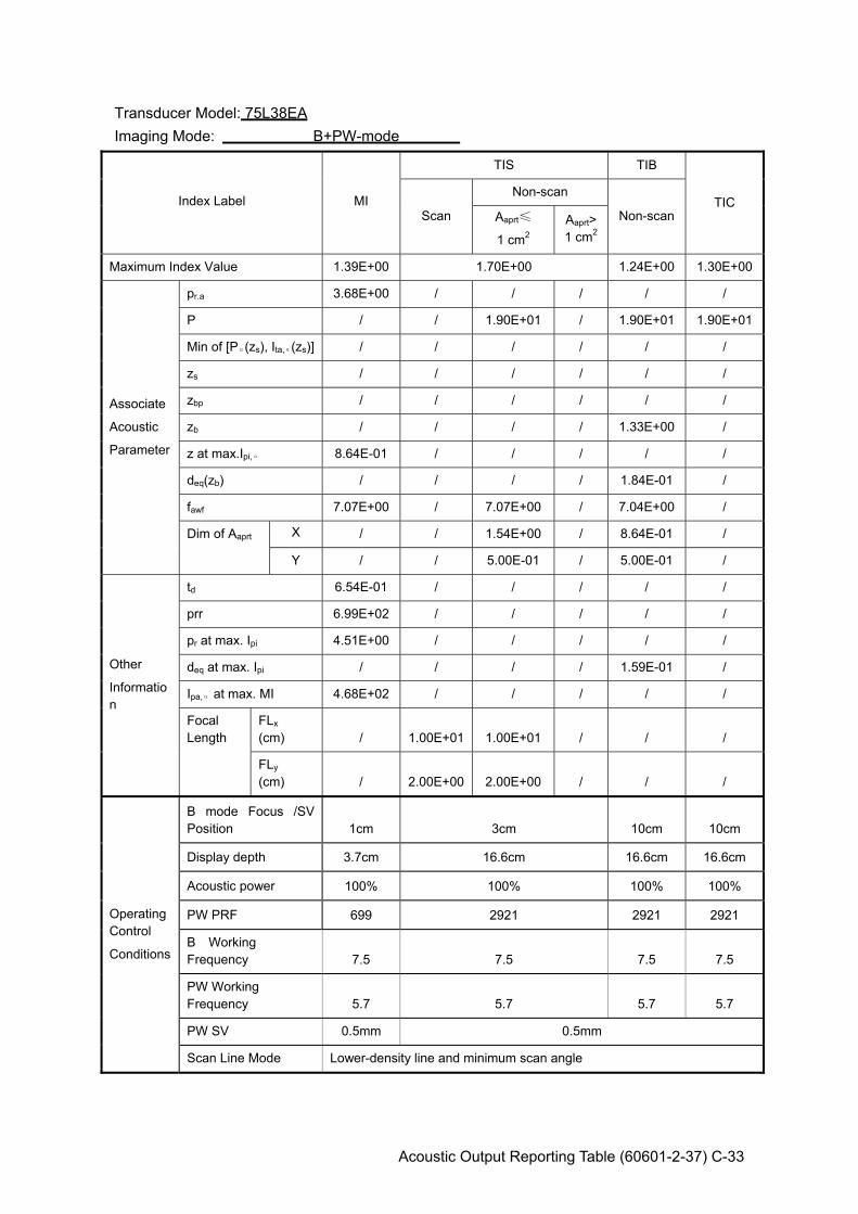
Acoustic Output Reporting Table (60601-2-37) C-33
Transducer Model: 75L38EA Imaging Mode: B+PW-mode
Index Label MI
TIS TIB
TIC Scan
Non-scan
Non-scan Aaprt≤
1 cm2 Aaprt> 1 cm2
Maximum Index Value 1.39E+00 1.70E+00 1.24E+00 1.30E+00
Associate
Acoustic
Parameter
pr.a 3.68E+00 / / / / /
P / / 1.90E+01 / 1.90E+01 1.90E+01
Min of [Pα(zs), Ita,α(zs)] / / / / / /
zs / / / / / /
zbp / / / / / /
zb / / / / 1.33E+00 /
z at max.Ipi,α 8.64E-01 / / / / /
deq(zb) / / / / 1.84E-01 /
fawf 7.07E+00 / 7.07E+00 / 7.04E+00 /
Dim of Aaprt X / / 1.54E+00 / 8.64E-01 /
Y / / 5.00E-01 / 5.00E-01 /
Other
Information
td 6.54E-01 / / / / /
prr 6.99E+02 / / / / /
pr at max. Ipi 4.51E+00 / / / / /
deq at max. Ipi / / / / 1.59E-01 /
Ipa,α at max. MI 4.68E+02 / / / / /
Focal Length
FLx (cm) / 1.00E+01 1.00E+01 / / /
FLy (cm) / 2.00E+00 2.00E+00 / / /
Operating Control
Conditions
B mode Focus /SV Position 1cm 3cm 10cm 10cm
Display depth 3.7cm 16.6cm 16.6cm 16.6cm
Acoustic power 100% 100% 100% 100%
PW PRF 699 2921 2921 2921
B Working Frequency 7.5 7.5 7.5 7.5
PW Working Frequency 5.7 5.7 5.7 5.7
PW SV 0.5mm 0.5mm
Scan Line Mode Lower-density line and minimum scan angle

C-34 Acoustic Output Reporting Table (60601-2-37)
Transducer Model: 75L38EA Imaging Mode: Color+B-Mode / Power+B-Mode
Index Label MI
TIS TIB
TIC Scan
Non-scan Non-
scan Aaprt≤
1cm2 Aaprt>1
cm2
Maximum Index Value 1.38E+00 1.43E+00 / / / 1.27E+00
Associate
Acoustic
Parameter
pr.a 3.47E+00 / / / / /
P / 4.01E+01 / / / 4.01E+01
Min of [Pα(zs), Ita,α(zs)] / / / / / /
zs / / / / / /
zbp / / / / / /
zb / / / / / /
z at max.Ipi,α 1.48E+00 / / / / /
deq(zb) / / / / / /
fawf 6.32E+00 / / / / /
Dim of Aaprt
X / / / / / /
Y / / / / / /
Other
Information
td 7.58E-01 / / / / /
prr 2.37E+03 / / / / /
pr at max. Ipi 4.74E+00 / / / / /
deq at max. Ipi / / / / / /
Ipa,α at max. MI 5.44E+02 / / / / /
Focal Length
FLx (cm) / / / /
/ /
FLy (cm) /
/ / / / /
Operating Control
Conditions
B Focus /Color Sampling Gate Positon
2cm 10cm 10cm 10cm
Display depth 16.6cm 16.6cm 16.6cm 16.6cm
Acoustic power 100% 100% 100% 100%
Color PRF 2373 2521 2521 2521
B Working Frequency 5 7.5 7.5 7.5
C Working Frequency 5 5.7 5.7 5.7
Color Sampling Gate Width minimum minimum
Scan Line Mode Minimum scan angle and lower-density line for B-mode and Color-mode color sensitivity:2
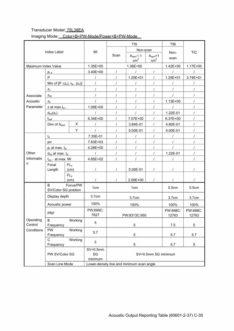
Acoustic Output Reporting Table (60601-2-37) C-35
Transducer Model: 75L38EA Imaging Mode: Color+B+PW-Mode/Power+B+PW-Mode
Index Label MI
TIS TIB
TIC Scan
Non-scan Non- scan Aaprt≤1
cm2 Aaprt>1
cm2 Maximum Index Value 1.35E+00 1.36E+00 1.42E+00 1.17E+00
Associate Acoustic Parameter
pr.a 3.40E+00 / / / / / P / / 1.25E+01 / 1.25E+01 3.74E+01Min of [Pα(zs), Ita,α(zs)] / / / / / / zs / / / / / / zbp / / / / / / zb / / / / 1.13E+00 / z at max.Ipi,α 1.09E+00 / / / / / deq(zb) / / / / 1.22E-01 / fawf 6.34E+00 / 7.07E+00 / 6.37E+00 / Dim of Aaprt X / / 3.84E-01 / 4.80E-01 /
Y / / 5.00E-01 / 5.00E-01 /
Other Information
td 7.35E-01 / / / / / prr 7.63E+03 / / / / / pr at max. Ipi 4.28E+00 / / / / / deq at max. Ipi / / / / 1.22E-01 / Ipa,α at max. MI 4.85E+02 / / / / / Focal Length
FLx (cm) / / 5.00E-01 / / / FLy (cm) / / 2.00E+00 / / /
Operating Control Conditions
B Focus/PW SV/Color SG position
1cm 1cm 0.5cm 0.5cm
Display depth 3.7cm 3.7cm 3.7cm 3.7cm
Acoustic power 100% 100% 100% 100%
PRF PW:699C:
7627 PW:8313C:950 PW:698C:
12763 PW:698C:
12763 B Working Frequency
5 5 7.5 5 PW Working Frequency
5.7 5 5.7 5.7
C Working Frequency
5 5 5.7 5
PW SV/Color SG SV=0.5mm
SG minimum
SV=0.5mm SG minimum
Scan Line Mode Lower-density line and minimum scan angle
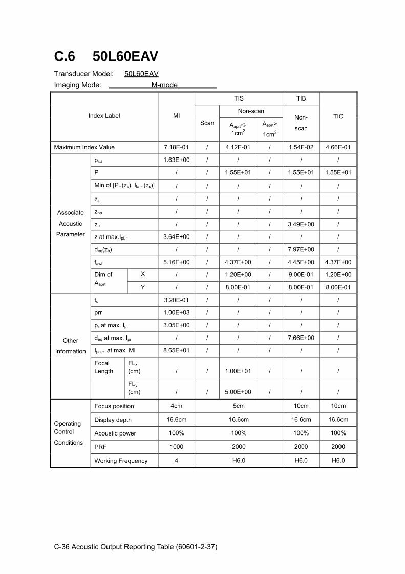
C-36 Acoustic Output Reporting Table (60601-2-37)
C.6 50L60EAV Transducer Model: 50L60EAV Imaging Mode: M-mode
Index Label MI
TIS TIB
TIC Scan
Non-scan Non-
scan Aaprt≤
1cm2 Aaprt>
1cm2
Maximum Index Value 7.18E-01 / 4.12E-01 / 1.54E-02 4.66E-01
Associate
Acoustic
Parameter
pr.a 1.63E+00 / / / / /
P / / 1.55E+01 / 1.55E+01 1.55E+01
Min of [Pα(zs), Ita,α(zs)] / / / / / /
zs / / / / / /
zbp / / / / / /
zb / / / / 3.49E+00 /
z at max.Ipi,α 3.64E+00 / / / / /
deq(zb) / / / / 7.97E+00 /
fawf 5.16E+00 / 4.37E+00 / 4.45E+00 4.37E+00
Dim of Aaprt
X / / 1.20E+00 / 9.00E-01 1.20E+00
Y / / 8.00E-01 / 8.00E-01 8.00E-01
Other
Information
td 3.20E-01 / / / / /
prr 1.00E+03 / / / / /
pr at max. Ipi 3.05E+00 / / / / /
deq at max. Ipi / / / / 7.66E+00 /
Ipa,α at max. MI 8.65E+01 / / / / /
Focal Length
FLx (cm) / / 1.00E+01 / / /
FLy (cm) / / 5.00E+00 / / /
Operating Control
Conditions
Focus position 4cm 5cm 10cm 10cm
Display depth 16.6cm 16.6cm 16.6cm 16.6cm
Acoustic power 100% 100% 100% 100%
PRF 1000 2000 2000 2000
Working Frequency 4 H6.0 H6.0 H6.0

Acoustic Output Reporting Table (60601-2-37) C-37
Transducer Model: 50L60EAV Imaging Mode: B-mode Smart3D iScape Free Xros M
Index Label MI
TIS TIB
TIC Scan
Non-scan Non-
scan Aaprt≤
1 cm2 Aaprt> 1
cm2
Maximum Index Value 6.50E-01 3.34E-01 / / / 3.77E-01
Associate
Acoustic
Parameter
pr.a 1.52E+00 / / / / /
P / 1.50E+01 / / / 1.50E+01
Min of [Pα(zs), Ita,α(zs)] / / / / / /
zs / / / / / /
zbp / / / / / /
zb / / / / / /
z at max.Ipi,α 3.73E+00 / / / / /
deq(zb) / / / / / /
fawf 6.10E+00 4.41E+00 / / / 4.40E+00
Dim of Aaprt X / 1.20E+00 / / / 1.20E+00
Y / 8.00E-01 / / / 8.00E-01
Other
Information
td 2.89E-01 / / / / /
prr 3.99E+03 / / / / /
pr at max. Ipi 3.26E+00 / / / / /
deq at max. Ipi / / / / / /
Ipa,α at max. MI 1.08E+02 / / / / /
Focal Length
FLx (cm) / 1.00E+01 / / / 9.00E+00
FLy (cm) / 5.00E+00 / / / 5.00E+00
Operating Control
Conditions
Focus position 4cm 10cm 10cm 9cm
Display depth 16.6cm 16.6cm 16.6cm 16.6cm
Acoustic power 100% 100% 100% 100%
Focus number one one one one
Working Frequency 5 H6.0 H6.0 H6.0
Scan Line Mode Lower-density line and minimum scan angle
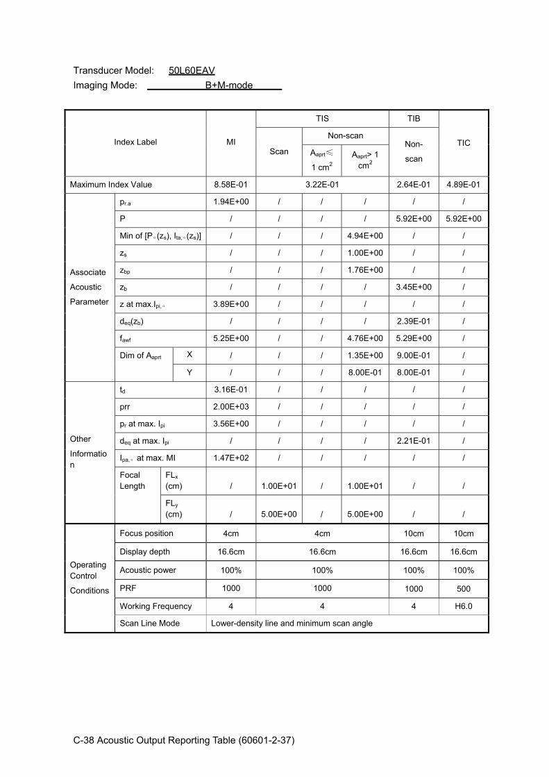
C-38 Acoustic Output Reporting Table (60601-2-37)
Transducer Model: 50L60EAV Imaging Mode: B+M-mode
Index Label MI
TIS TIB
TIC Scan
Non-scan Non-
scan Aaprt≤
1 cm2 Aaprt> 1
cm2
Maximum Index Value 8.58E-01 3.22E-01 2.64E-01 4.89E-01
Associate
Acoustic
Parameter
pr.a 1.94E+00 / / / / /
P / / / / 5.92E+00 5.92E+00
Min of [Pα(zs), Ita,α(zs)] / / / 4.94E+00 / /
zs / / / 1.00E+00 / /
zbp / / / 1.76E+00 / /
zb / / / / 3.45E+00 /
z at max.Ipi,α 3.89E+00 / / / / /
deq(zb) / / / / 2.39E-01 /
fawf 5.25E+00 / / 4.76E+00 5.29E+00 /
Dim of Aaprt X / / / 1.35E+00 9.00E-01 /
Y / / / 8.00E-01 8.00E-01 /
Other
Information
td 3.16E-01 / / / / /
prr 2.00E+03 / / / / /
pr at max. Ipi 3.56E+00 / / / / /
deq at max. Ipi / / / / 2.21E-01 /
Ipa,α at max. MI 1.47E+02 / / / / /
Focal Length
FLx (cm) / 1.00E+01 / 1.00E+01 / /
FLy (cm) / 5.00E+00 / 5.00E+00 / /
Operating Control
Conditions
Focus position 4cm 4cm 10cm 10cm
Display depth 16.6cm 16.6cm 16.6cm 16.6cm
Acoustic power 100% 100% 100% 100%
PRF 1000 1000 1000 500
Working Frequency 4 4 4 H6.0
Scan Line Mode Lower-density line and minimum scan angle
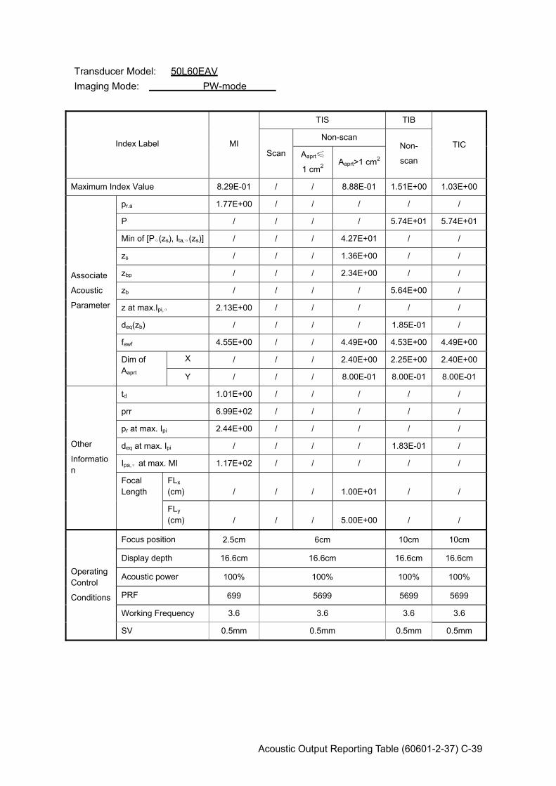
Acoustic Output Reporting Table (60601-2-37) C-39
Transducer Model: 50L60EAV Imaging Mode: PW-mode
Index Label MI
TIS TIB
TIC Scan
Non-scan Non-
scan Aaprt≤
1 cm2 Aaprt>1 cm2
Maximum Index Value 8.29E-01 / / 8.88E-01 1.51E+00 1.03E+00
Associate
Acoustic
Parameter
pr.a 1.77E+00 / / / / /
P / / / / 5.74E+01 5.74E+01
Min of [Pα(zs), Ita,α(zs)] / / / 4.27E+01 / /
zs / / / 1.36E+00 / /
zbp / / / 2.34E+00 / /
zb / / / / 5.64E+00 /
z at max.Ipi,α 2.13E+00 / / / / /
deq(zb) / / / / 1.85E-01 /
fawf 4.55E+00 / / 4.49E+00 4.53E+00 4.49E+00
Dim of Aaprt
X / / / 2.40E+00 2.25E+00 2.40E+00
Y / / / 8.00E-01 8.00E-01 8.00E-01
Other
Information
td 1.01E+00 / / / / /
prr 6.99E+02 / / / / /
pr at max. Ipi 2.44E+00 / / / / /
deq at max. Ipi / / / / 1.83E-01 /
Ipa,α at max. MI 1.17E+02 / / / / /
Focal Length
FLx (cm) / / / 1.00E+01 / /
FLy (cm) / / / 5.00E+00 / /
Operating Control
Conditions
Focus position 2.5cm 6cm 10cm 10cm
Display depth 16.6cm 16.6cm 16.6cm 16.6cm
Acoustic power 100% 100% 100% 100%
PRF 699 5699 5699 5699
Working Frequency 3.6 3.6 3.6 3.6
SV 0.5mm 0.5mm 0.5mm 0.5mm
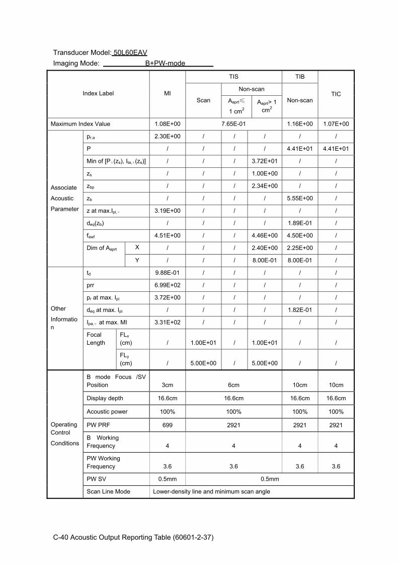
C-40 Acoustic Output Reporting Table (60601-2-37)
Transducer Model: 50L60EAV Imaging Mode: B+PW-mode
Index Label MI
TIS TIB
TIC Scan
Non-scan
Non-scan Aaprt≤
1 cm2 Aaprt> 1
cm2
Maximum Index Value 1.08E+00 7.65E-01 1.16E+00 1.07E+00
Associate
Acoustic
Parameter
pr.a 2.30E+00 / / / / /
P / / / / 4.41E+01 4.41E+01
Min of [Pα(zs), Ita,α(zs)] / / / 3.72E+01 / /
zs / / / 1.00E+00 / /
zbp / / / 2.34E+00 / /
zb / / / / 5.55E+00 /
z at max.Ipi,α 3.19E+00 / / / / /
deq(zb) / / / / 1.89E-01 /
fawf 4.51E+00 / / 4.46E+00 4.50E+00 /
Dim of Aaprt X / / / 2.40E+00 2.25E+00 /
Y / / / 8.00E-01 8.00E-01 /
Other
Information
td 9.88E-01 / / / / /
prr 6.99E+02 / / / / /
pr at max. Ipi 3.72E+00 / / / / /
deq at max. Ipi / / / / 1.82E-01 /
Ipa,α at max. MI 3.31E+02 / / / / /
Focal Length
FLx (cm) / 1.00E+01 / 1.00E+01 / /
FLy (cm) / 5.00E+00 / 5.00E+00 / /
Operating Control
Conditions
B mode Focus /SV Position 3cm 6cm 10cm 10cm
Display depth 16.6cm 16.6cm 16.6cm 16.6cm
Acoustic power 100% 100% 100% 100%
PW PRF 699 2921 2921 2921
B Working Frequency 4 4 4 4
PW Working Frequency 3.6 3.6 3.6 3.6
PW SV 0.5mm 0.5mm
Scan Line Mode Lower-density line and minimum scan angle

Acoustic Output Reporting Table (60601-2-37) C-41
Transducer Model: 50L60EAV Imaging Mode: Color+B-Mode / Power+B-Mode
Index Label MI
TIS TIB
TIC Scan
Non-scan Non-
scan Aaprt≤
1cm2 Aaprt>1
cm2
Maximum Index Value 8.96E-01 5.73E-01 / / / 6.28E-01
Associate
Acoustic
Parameter
pr.a 1.91E+00 / / / / /
P / 2.61E+01 / / / 2.61E+01
Min of [Pα(zs), Ita,α(zs)] / / / / / /
zs / / / / / /
zbp / / / / / /
zb / / / / / /
z at max.Ipi,α 3.16E+00 / / / / /
deq(zb) / / / / / /
fawf 4.52E+00 / / / / /
Dim of Aaprt
X / / / / / /
Y / / / / / /
Other
Information
td 9.63E-01 / / / / /
prr 6.31E+02 / / / / /
pr at max. Ipi 3.08E+00 / / / / /
deq at max. Ipi / / / / / /
Ipa,α at max. MI 2.03E+02 / / / / /
Focal Length
FLx (cm) / / / /
/ /
FLy (cm) /
/ / / / /
Operating Control
Conditions
B Focus /Color Sampling Gate Positon
3cm 10cm 10cm 10cm
Display depth 16.6cm 16.6cm 16.6cm 16.6cm
Acoustic power 100% 100% 100% 100%
Color PRF 631 631 631 631
B Working Frequency 4 4 4 4
C Working Frequency 3.6 3.6 3.6 3.6
Color Sampling Gate Width minimum minimum
Scan Line Mode Minimum scan angle and lower-density line for B-mode and Color-mode color sensitivity:2
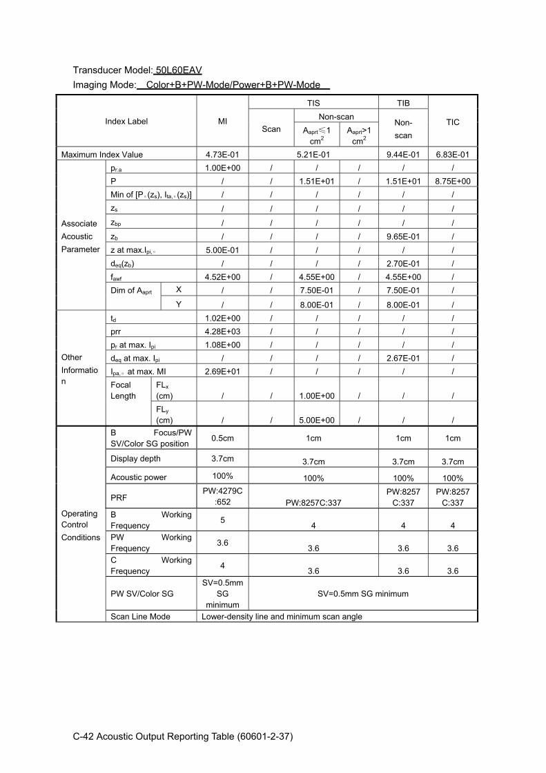
C-42 Acoustic Output Reporting Table (60601-2-37)
Transducer Model: 50L60EAV Imaging Mode: Color+B+PW-Mode/Power+B+PW-Mode
Index Label MI
TIS TIB
TIC Scan
Non-scan Non- scan Aaprt≤1
cm2 Aaprt>1
cm2 Maximum Index Value 4.73E-01 5.21E-01 9.44E-01 6.83E-01
Associate Acoustic Parameter
pr.a 1.00E+00 / / / / / P / / 1.51E+01 / 1.51E+01 8.75E+00Min of [Pα(zs), Ita,α(zs)] / / / / / / zs / / / / / / zbp / / / / / / zb / / / / 9.65E-01 / z at max.Ipi,α 5.00E-01 / / / / / deq(zb) / / / / 2.70E-01 / fawf 4.52E+00 / 4.55E+00 / 4.55E+00 / Dim of Aaprt X / / 7.50E-01 / 7.50E-01 /
Y / / 8.00E-01 / 8.00E-01 /
Other Information
td 1.02E+00 / / / / / prr 4.28E+03 / / / / / pr at max. Ipi 1.08E+00 / / / / / deq at max. Ipi / / / / 2.67E-01 / Ipa,α at max. MI 2.69E+01 / / / / / Focal Length
FLx (cm) / / 1.00E+00 / / / FLy (cm) / / 5.00E+00 / / /
Operating Control Conditions
B Focus/PW SV/Color SG position
0.5cm 1cm 1cm 1cm
Display depth 3.7cm 3.7cm 3.7cm 3.7cm
Acoustic power 100% 100% 100% 100%
PRF PW:4279C
:652 PW:8257C:337 PW:8257
C:337 PW:8257
C:337 B Working Frequency
5 4 4 4 PW Working Frequency
3.6 3.6 3.6 3.6
C Working Frequency
4 3.6 3.6 3.6
PW SV/Color SG SV=0.5mm
SG minimum
SV=0.5mm SG minimum
Scan Line Mode Lower-density line and minimum scan angle
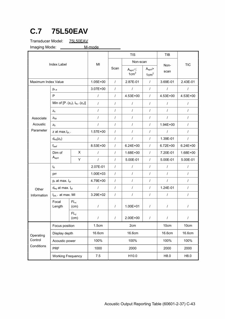
Acoustic Output Reporting Table (60601-2-37) C-43
C.7 75L50EAV Transducer Model: 75L50EAV Imaging Mode: M-mode
Index Label MI
TIS TIB
TIC Scan
Non-scan Non-
scan Aaprt≤
1cm2 Aaprt>
1cm2
Maximum Index Value 1.05E+00 / 2.87E-01 / 3.69E-01 2.43E-01
Associate
Acoustic
Parameter
pr.a 3.07E+00 / / / / /
P / / 4.53E+00 / 4.53E+00 4.53E+00
Min of [Pα(zs), Ita,α(zs)] / / / / / /
zs / / / / / /
zbp / / / / / /
zb / / / / 1.94E+00 /
z at max.Ipi,α 1.57E+00 / / / / /
deq(zb) / / / / 1.39E-01 /
fawf 8.53E+00 / 6.24E+00 / 6.72E+00 6.24E+00
Dim of Aaprt
X / / 1.68E+00 / 7.20E-01 1.68E+00
Y / / 5.00E-01 / 5.00E-01 5.00E-01
Other
Information
td 2.07E-01 / / / / /
prr 1.00E+03 / / / / /
pr at max. Ipi 4.79E+00 / / / / /
deq at max. Ipi / / / / 1.24E-01 /
Ipa,α at max. MI 3.29E+02 / / / / /
Focal Length
FLx (cm) / / 1.00E+01 / / /
FLy (cm) / / 2.00E+00 / / /
Operating Control
Conditions
Focus position 1.5cm 2cm 10cm 10cm
Display depth 16.6cm 16.6cm 16.6cm 16.6cm
Acoustic power 100% 100% 100% 100%
PRF 1000 2000 2000 2000
Working Frequency 7.5 H10.0 H8.0 H8.0
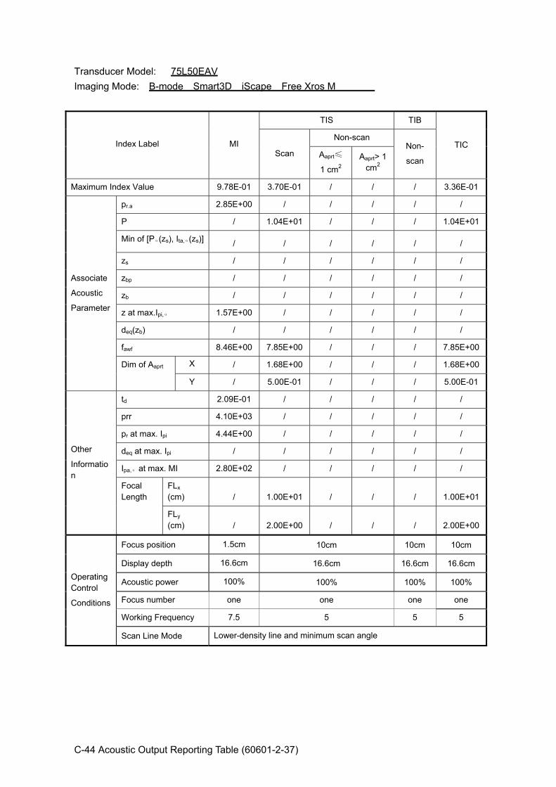
C-44 Acoustic Output Reporting Table (60601-2-37)
Transducer Model: 75L50EAV Imaging Mode: B-mode Smart3D iScape Free Xros M
Index Label MI
TIS TIB
TIC Scan
Non-scan Non-
scan Aaprt≤
1 cm2 Aaprt> 1
cm2
Maximum Index Value 9.78E-01 3.70E-01 / / / 3.36E-01
Associate
Acoustic
Parameter
pr.a 2.85E+00 / / / / /
P / 1.04E+01 / / / 1.04E+01
Min of [Pα(zs), Ita,α(zs)] / / / / / /
zs / / / / / /
zbp / / / / / /
zb / / / / / /
z at max.Ipi,α 1.57E+00 / / / / /
deq(zb) / / / / / /
fawf 8.46E+00 7.85E+00 / / / 7.85E+00
Dim of Aaprt X / 1.68E+00 / / / 1.68E+00
Y / 5.00E-01 / / / 5.00E-01
Other
Information
td 2.09E-01 / / / / /
prr 4.10E+03 / / / / /
pr at max. Ipi 4.44E+00 / / / / /
deq at max. Ipi / / / / / /
Ipa,α at max. MI 2.80E+02 / / / / /
Focal Length
FLx (cm) / 1.00E+01 / / / 1.00E+01
FLy (cm) / 2.00E+00 / / / 2.00E+00
Operating Control
Conditions
Focus position 1.5cm 10cm 10cm 10cm
Display depth 16.6cm 16.6cm 16.6cm 16.6cm
Acoustic power 100% 100% 100% 100%
Focus number one one one one
Working Frequency 7.5 5 5 5
Scan Line Mode Lower-density line and minimum scan angle
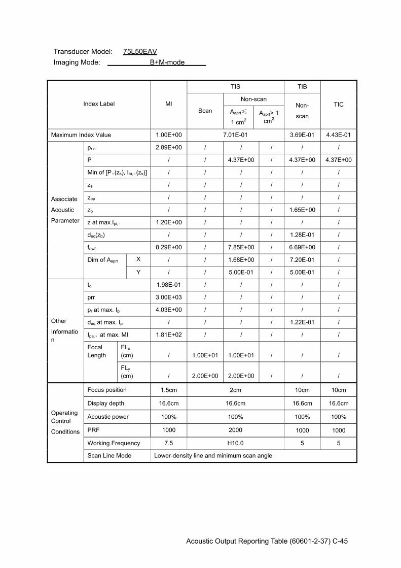
Acoustic Output Reporting Table (60601-2-37) C-45
Transducer Model: 75L50EAV Imaging Mode: B+M-mode
Index Label MI
TIS TIB
TIC Scan
Non-scan Non-
scan Aaprt≤
1 cm2 Aaprt> 1
cm2
Maximum Index Value 1.00E+00 7.01E-01 3.69E-01 4.43E-01
Associate
Acoustic
Parameter
pr.a 2.89E+00 / / / / /
P / / 4.37E+00 / 4.37E+00 4.37E+00
Min of [Pα(zs), Ita,α(zs)] / / / / / /
zs / / / / / /
zbp / / / / / /
zb / / / / 1.65E+00 /
z at max.Ipi,α 1.20E+00 / / / / /
deq(zb) / / / / 1.28E-01 /
fawf 8.29E+00 / 7.85E+00 / 6.69E+00 /
Dim of Aaprt X / / 1.68E+00 / 7.20E-01 /
Y / / 5.00E-01 / 5.00E-01 /
Other
Information
td 1.98E-01 / / / / /
prr 3.00E+03 / / / / /
pr at max. Ipi 4.03E+00 / / / / /
deq at max. Ipi / / / / 1.22E-01 /
Ipa,α at max. MI 1.81E+02 / / / / /
Focal Length
FLx (cm) / 1.00E+01 1.00E+01 / / /
FLy (cm) / 2.00E+00 2.00E+00 / / /
Operating Control
Conditions
Focus position 1.5cm 2cm 10cm 10cm
Display depth 16.6cm 16.6cm 16.6cm 16.6cm
Acoustic power 100% 100% 100% 100%
PRF 1000 2000 1000 1000
Working Frequency 7.5 H10.0 5 5
Scan Line Mode Lower-density line and minimum scan angle
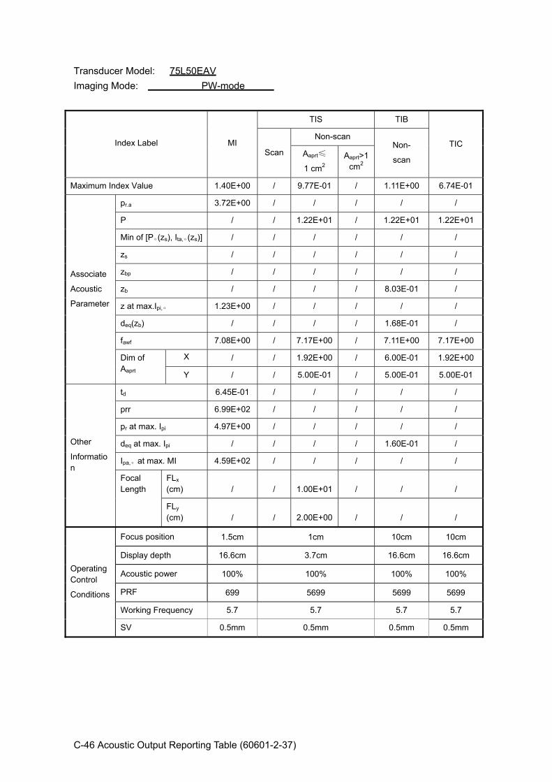
C-46 Acoustic Output Reporting Table (60601-2-37)
Transducer Model: 75L50EAV Imaging Mode: PW-mode
Index Label MI
TIS TIB
TIC Scan
Non-scan Non-
scan Aaprt≤
1 cm2 Aaprt>1
cm2
Maximum Index Value 1.40E+00 / 9.77E-01 / 1.11E+00 6.74E-01
Associate
Acoustic
Parameter
pr.a 3.72E+00 / / / / /
P / / 1.22E+01 / 1.22E+01 1.22E+01
Min of [Pα(zs), Ita,α(zs)] / / / / / /
zs / / / / / /
zbp / / / / / /
zb / / / / 8.03E-01 /
z at max.Ipi,α 1.23E+00 / / / / /
deq(zb) / / / / 1.68E-01 /
fawf 7.08E+00 / 7.17E+00 / 7.11E+00 7.17E+00
Dim of Aaprt
X / / 1.92E+00 / 6.00E-01 1.92E+00
Y / / 5.00E-01 / 5.00E-01 5.00E-01
Other
Information
td 6.45E-01 / / / / /
prr 6.99E+02 / / / / /
pr at max. Ipi 4.97E+00 / / / / /
deq at max. Ipi / / / / 1.60E-01 /
Ipa,α at max. MI 4.59E+02 / / / / /
Focal Length
FLx (cm) / / 1.00E+01 / / /
FLy (cm) / / 2.00E+00 / / /
Operating Control
Conditions
Focus position 1.5cm 1cm 10cm 10cm
Display depth 16.6cm 3.7cm 16.6cm 16.6cm
Acoustic power 100% 100% 100% 100%
PRF 699 5699 5699 5699
Working Frequency 5.7 5.7 5.7 5.7
SV 0.5mm 0.5mm 0.5mm 0.5mm
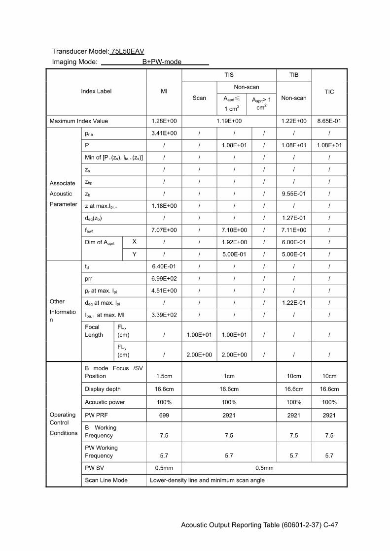
Acoustic Output Reporting Table (60601-2-37) C-47
Transducer Model: 75L50EAV Imaging Mode: B+PW-mode
Index Label MI
TIS TIB
TIC Scan
Non-scan
Non-scan Aaprt≤
1 cm2 Aaprt> 1
cm2
Maximum Index Value 1.28E+00 1.19E+00 1.22E+00 8.65E-01
Associate
Acoustic
Parameter
pr.a 3.41E+00 / / / / /
P / / 1.08E+01 / 1.08E+01 1.08E+01
Min of [Pα(zs), Ita,α(zs)] / / / / / /
zs / / / / / /
zbp / / / / / /
zb / / / / 9.55E-01 /
z at max.Ipi,α 1.18E+00 / / / / /
deq(zb) / / / / 1.27E-01 /
fawf 7.07E+00 / 7.10E+00 / 7.11E+00 /
Dim of Aaprt X / / 1.92E+00 / 6.00E-01 /
Y / / 5.00E-01 / 5.00E-01 /
Other
Information
td 6.40E-01 / / / / /
prr 6.99E+02 / / / / /
pr at max. Ipi 4.51E+00 / / / / /
deq at max. Ipi / / / / 1.22E-01 /
Ipa,α at max. MI 3.39E+02 / / / / /
Focal Length
FLx (cm) / 1.00E+01 1.00E+01 / / /
FLy (cm) / 2.00E+00 2.00E+00 / / /
Operating Control
Conditions
B mode Focus /SV Position 1.5cm 1cm 10cm 10cm
Display depth 16.6cm 16.6cm 16.6cm 16.6cm
Acoustic power 100% 100% 100% 100%
PW PRF 699 2921 2921 2921
B Working Frequency 7.5 7.5 7.5 7.5
PW Working Frequency 5.7 5.7 5.7 5.7
PW SV 0.5mm 0.5mm
Scan Line Mode Lower-density line and minimum scan angle
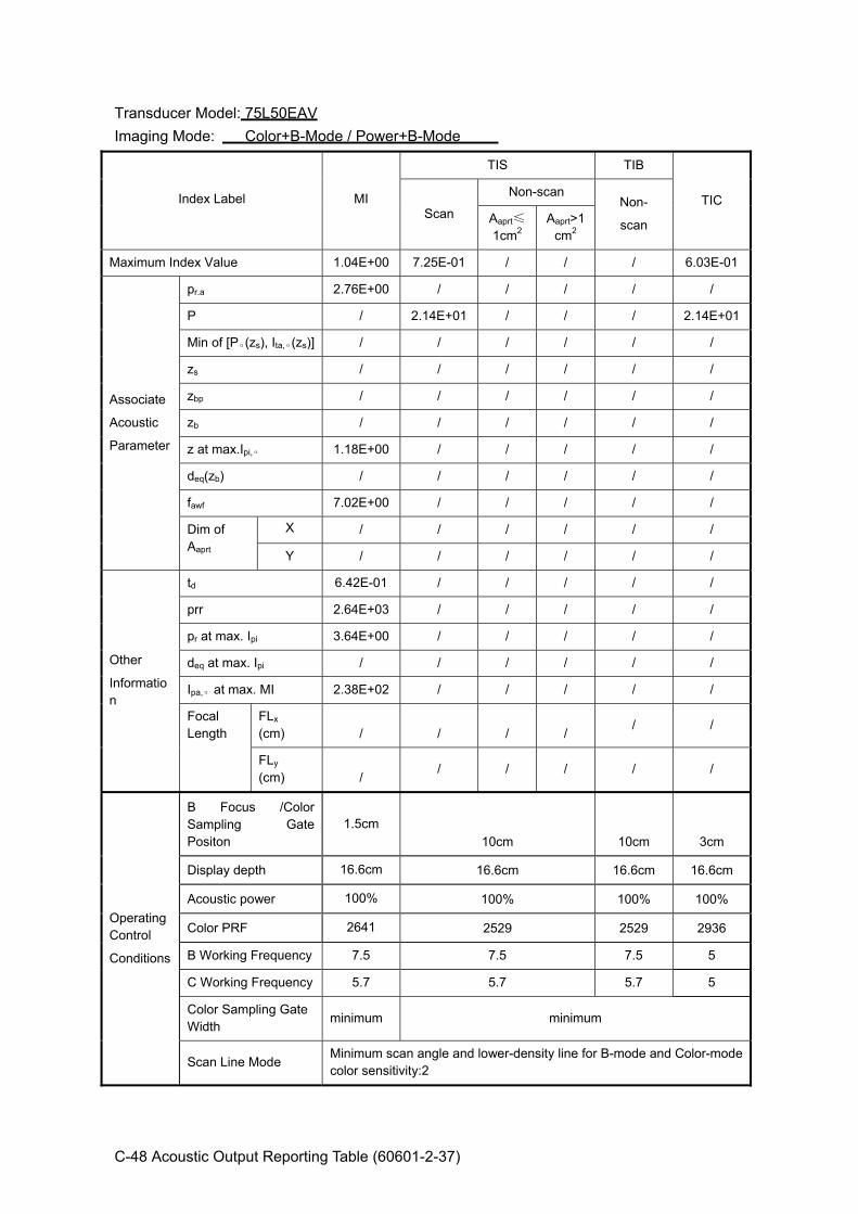
C-48 Acoustic Output Reporting Table (60601-2-37)
Transducer Model: 75L50EAV Imaging Mode: Color+B-Mode / Power+B-Mode
Index Label MI
TIS TIB
TIC Scan
Non-scan Non-
scan Aaprt≤
1cm2 Aaprt>1
cm2
Maximum Index Value 1.04E+00 7.25E-01 / / / 6.03E-01
Associate
Acoustic
Parameter
pr.a 2.76E+00 / / / / /
P / 2.14E+01 / / / 2.14E+01
Min of [Pα(zs), Ita,α(zs)] / / / / / /
zs / / / / / /
zbp / / / / / /
zb / / / / / /
z at max.Ipi,α 1.18E+00 / / / / /
deq(zb) / / / / / /
fawf 7.02E+00 / / / / /
Dim of Aaprt
X / / / / / /
Y / / / / / /
Other
Information
td 6.42E-01 / / / / /
prr 2.64E+03 / / / / /
pr at max. Ipi 3.64E+00 / / / / /
deq at max. Ipi / / / / / /
Ipa,α at max. MI 2.38E+02 / / / / /
Focal Length
FLx (cm) / / / /
/ /
FLy (cm) /
/ / / / /
Operating Control
Conditions
B Focus /Color Sampling Gate Positon
1.5cm 10cm 10cm 3cm
Display depth 16.6cm 16.6cm 16.6cm 16.6cm
Acoustic power 100% 100% 100% 100%
Color PRF 2641 2529 2529 2936
B Working Frequency 7.5 7.5 7.5 5
C Working Frequency 5.7 5.7 5.7 5
Color Sampling Gate Width minimum minimum
Scan Line Mode Minimum scan angle and lower-density line for B-mode and Color-mode color sensitivity:2

Acoustic Output Reporting Table (60601-2-37) C-49
Transducer Model: 75L50EAV Imaging Mode: Color+B+PW-Mode/Power+B+PW-Mode
Index Label MI
TIS TIB
TIC Scan
Non-scan Non- scan Aaprt≤1
cm2 Aaprt>1 cm2
Maximum Index Value 1.17E+00 1.02E+00 1.18E+00 8.99E-01
Associate Acoustic Parameter
pr.a 2.93E+00 / / / / / P / / 1.05E+01 / 1.05E+01 2.70E+01Min of [Pα(zs), Ita,α(zs)] / / / / / / zs / / / / / / zbp / / / / / / zb / / / / 1.10E+00 / z at max.Ipi,α 1.03E+00 / / / / / deq(zb) / / / / 1.19E-01 / fawf 6.34E+00 / 7.17E+00 / 7.13E+00 / Dim of Aaprt X / / 4.80E-01 / 6.00E-01 /
Y / / 5.00E-01 / 5.00E-01 /
Other Information
td 7.34E-01 / / / / / prr 7.63E+03 / / / / / pr at max. Ipi 3.64E+00 / / / / / deq at max. Ipi / / / / 1.18E-01 / Ipa,α at max. MI 3.21E+02 / / / / / Focal Length
FLx (cm) / / 5.00E-01 / / / FLy (cm) / / 2.00E+00 / / /
Operating Control Conditions
B Focus/PW SV/Color SG position
1cm 1cm 0.5cm 0.5cm
Display depth 3.7cm 3.7cm 3.7cm 3.7cm
Acoustic power 100% 100% 100% 100%
PRF PW:699C:
7627 PW:4287C:782 PW:698C:
12763 PW:698C:
12763 B Working Frequency
5 5 7.5 7.5 PW Working Frequency
5.7 5.7 5.7 5.7
C Working Frequency
5 5 5.7 5.7
PW SV/Color SG SV=0.5mm
SG minimum
SV=0.5mm SG minimum
Scan Line Mode Lower-density line and minimum scan angle

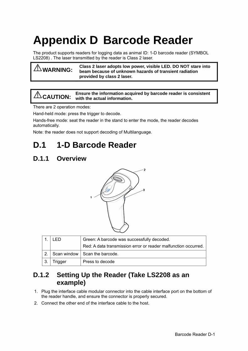
Barcode Reader D-1
Appendix D Barcode Reader The product supports readers for logging data as animal ID: 1-D barcode reader (SYMBOL LS2208) . The laser transmitted by the reader is Class 2 laser.
WARNING: Class 2 laser adopts low power, visible LED. DO NOT stare into beam because of unknown hazards of transient radiation provided by class 2 laser.
CAUTION: Ensure the information acquired by barcode reader is consistent with the actual information.
There are 2 operation modes: Hand-held mode: press the trigger to decode. Hands-free mode: seat the reader in the stand to enter the mode, the reader decodes automatically. Note: the reader does not support decoding of Multilanguage.
D.1 1-D Barcode Reader D.1.1 Overview
1. LED Green: A barcode was successfully decoded. Red: A data transmission error or reader malfunction occurred.
2. Scan window Scan the barcode.
3. Trigger Press to decode
D.1.2 Setting Up the Reader (Take LS2208 as an example)
1. Plug the interface cable modular connector into the cable interface port on the bottom of the reader handle, and ensure the connector is properly secured.
2. Connect the other end of the interface cable to the host.
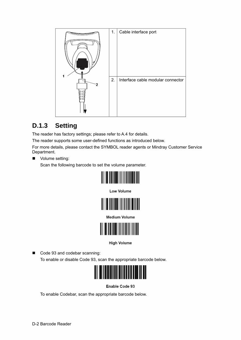
D-2 Barcode Reader
1. Cable interface port
2. Interface cable modular connector
D.1.3 Setting The reader has factory settings; please refer to A.4 for details. The reader supports some user-defined functions as introduced below. For more details, please contact the SYMBOL reader agents or Mindray Customer Service Department.
Volume setting: Scan the following barcode to set the volume parameter.
Code 93 and codebar scanning:
To enable or disable Code 93, scan the appropriate barcode below.
To enable Codebar, scan the appropriate barcode below.
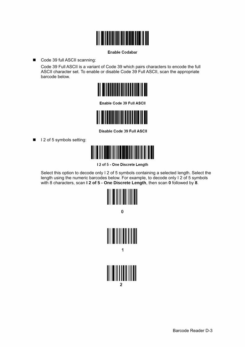
Barcode Reader D-3
Code 39 full ASCII scanning:
Code 39 Full ASCII is a variant of Code 39 which pairs characters to encode the full ASCII character set. To enable or disable Code 39 Full ASCII, scan the appropriate barcode below.
I 2 of 5 symbols setting:
Select this option to decode only I 2 of 5 symbols containing a selected length. Select the length using the numeric barcodes below. For example, to decode only I 2 of 5 symbols with 8 characters, scan I 2 of 5 - One Discrete Length, then scan 0 followed by 8.

D-4 Barcode Reader
D.1.4 Scanning in Hand-Held Mode 1. Ensure all connections are secure. 2. Aim the reader at the barcode. Press the trigger.
Tips: Ensure the scan line crosses every bar and space of the symbol, see the figure below.
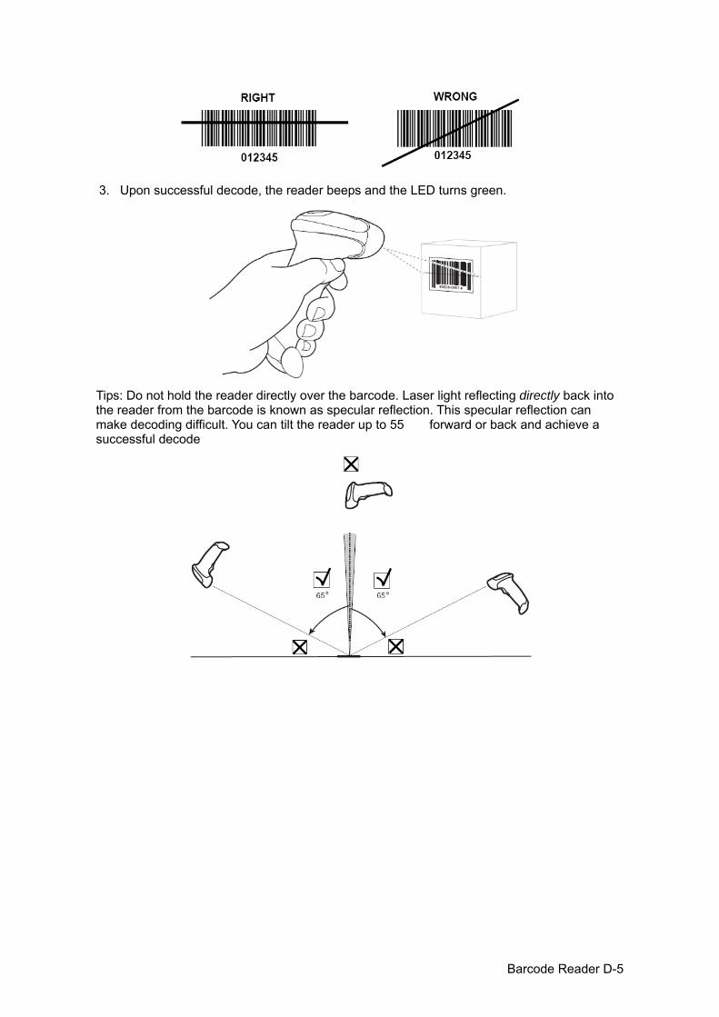
Barcode Reader D-5
3. Upon successful decode, the reader beeps and the LED turns green.
Tips: Do not hold the reader directly over the barcode. Laser light reflecting directly back into the reader from the barcode is known as specular reflection. This specular reflection can make decoding difficult. You can tilt the reader up to 55 forward or back and achieve a successful decode
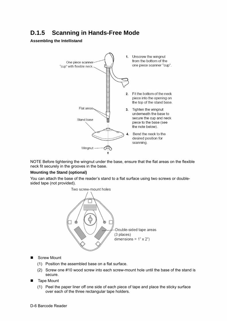
D-6 Barcode Reader
D.1.5 Scanning in Hands-Free Mode Assembling the Intellistand
NOTE Before tightening the wingnut under the base, ensure that the flat areas on the flexible neck fit securely in the grooves in the base. Mounting the Stand (optional) You can attach the base of the reader’s stand to a flat surface using two screws or double-sided tape (not provided).
Screw Mount
(1) Position the assembled base on a flat surface. (2) Screw one #10 wood screw into each screw-mount hole until the base of the stand is
secure. Tape Mount
(1) Peel the paper liner off one side of each piece of tape and place the sticky surface over each of the three rectangular tape holders.
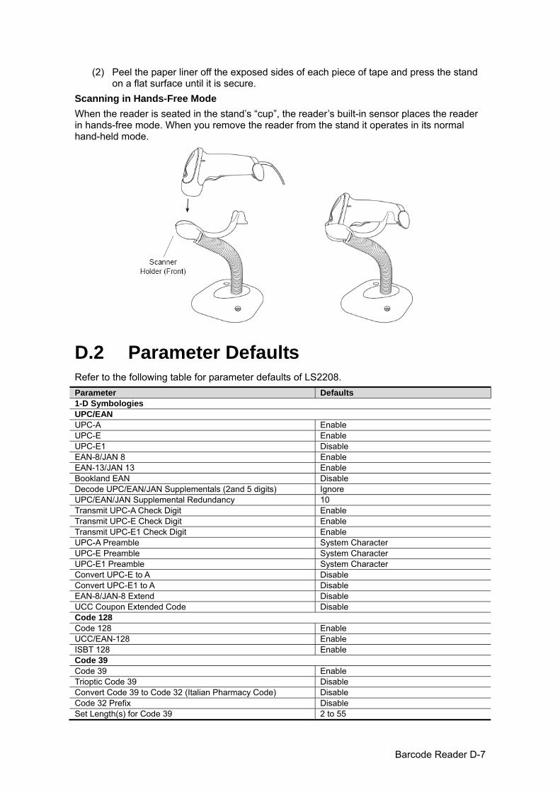
Barcode Reader D-7
(2) Peel the paper liner off the exposed sides of each piece of tape and press the stand on a flat surface until it is secure.
Scanning in Hands-Free Mode When the reader is seated in the stand’s “cup”, the reader’s built-in sensor places the reader in hands-free mode. When you remove the reader from the stand it operates in its normal hand-held mode.
D.2 Parameter Defaults Refer to the following table for parameter defaults of LS2208. Parameter Defaults1-D Symbologies UPC/EAN UPC-A Enable UPC-E Enable UPC-E1 Disable EAN-8/JAN 8 Enable EAN-13/JAN 13 Enable Bookland EAN Disable Decode UPC/EAN/JAN Supplementals (2and 5 digits) Ignore UPC/EAN/JAN Supplemental Redundancy 10 Transmit UPC-A Check Digit Enable Transmit UPC-E Check Digit Enable Transmit UPC-E1 Check Digit Enable UPC-A Preamble System Character UPC-E Preamble System Character UPC-E1 Preamble System Character Convert UPC-E to A Disable Convert UPC-E1 to A Disable EAN-8/JAN-8 Extend Disable UCC Coupon Extended Code Disable Code 128 Code 128 Enable UCC/EAN-128 Enable ISBT 128 Enable Code 39 Code 39 Enable Trioptic Code 39 Disable Convert Code 39 to Code 32 (Italian Pharmacy Code) Disable Code 32 Prefix Disable Set Length(s) for Code 39 2 to 55
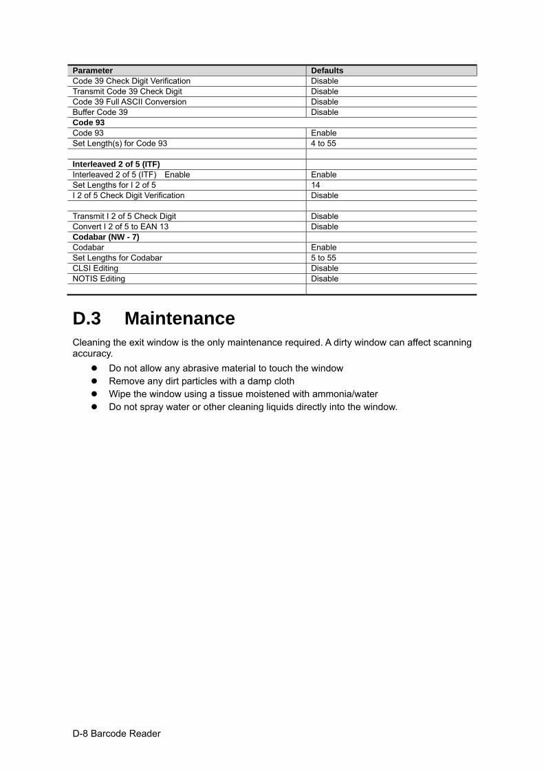
D-8 Barcode Reader
Parameter DefaultsCode 39 Check Digit Verification Disable Transmit Code 39 Check Digit Disable Code 39 Full ASCII Conversion Disable Buffer Code 39 Disable Code 93 Code 93 Enable Set Length(s) for Code 93 4 to 55 Interleaved 2 of 5 (ITF) Interleaved 2 of 5 (ITF) Enable Enable Set Lengths for I 2 of 5 14 I 2 of 5 Check Digit Verification Disable Transmit I 2 of 5 Check Digit Disable Convert I 2 of 5 to EAN 13 Disable Codabar (NW - 7) Codabar Enable Set Lengths for Codabar 5 to 55 CLSI Editing Disable NOTIS Editing Disable
D.3 Maintenance Cleaning the exit window is the only maintenance required. A dirty window can affect scanning accuracy.
Do not allow any abrasive material to touch the window Remove any dirt particles with a damp cloth Wipe the window using a tissue moistened with ammonia/water Do not spray water or other cleaning liquids directly into the window.

P/N: 046-004190-00 (V6.0)