york yk teardown
DESCRIPTION
York high pressure centrifugal teardown.TRANSCRIPT

SERVICE INSTRUCTION
CENTRIFUGAL COMPRESSORS
Supersedes: 160.49-M1 (1292) Form 160.49-M1 (601)
USED WITH YORK MODEL YKCENTRIFUGAL LIQUID CHILLERS
26439A
COMPRESSOR COMPRESSORMODEL CODEYDHF-39 P1YDHF-40 P2YDHF-42 P3YDHF-44 P4
YDHA-36 & LHA-36 G3YDHA-41 & LHA-41 G4YDHA-46 & LHA-46 H0
YDHA-50N & LHA-50N H1YDHA-50W & LHA-50W H1
YDHB-57, LHB-57, HA-57 H2YDHB-61 H3YDHD-46 H4
YDHD-50N & 50W H5YDHD-57 H6YDHD-59 H7YDHD-61 H8
YDHA-65 & LHA-65 J1YDHA-73 & LHA-73 J2YDHA-81 & LHA-81 J3YDHA-90 & LHA-90 J4
(Also see NOMENCLATURE, page 5)

YORK INTERNATIONAL2

FORM 160.49-M1
3YORK INTERNATIONAL
This equipment is a relatively complicated apparatus.During installation, operation, maintenance or service,individuals may be exposed to certain components orconditions including, but not limited to: refrigerants, oils,materials under pressure, rotating components, and bothhigh and low voltage. Each of these items has the po-tential, if misused or handled improperly, to cause bodilyinjury or death. It is the obligation and responsibility ofoperating/service personnel to identify and recognizethese inherent hazards, protect themselves, and proceedsafely in completing their tasks. Failure to comply withany of these requirements could result in serious dam-age to the equipment and the property in which it is
situated, as well as severe personal injury or death tothemselves and people at the site.
This document is intended for use by owner-authorizedoperating/service personnel. It is expected that this indi-vidual possesses independent training that will enablethem to perform their assigned tasks properly and safely.It is essential that, prior to performing any task on thisequipment, this individual shall have read and understoodthis document and any referenced materials. This indi-vidual shall also be familiar with and comply with allapplicable governmental standards and regulations per-taining to the task in question.
SAFETY SYMBOLS
The following symbols are used in this document to alert the reader to areas of potential hazard:
WARNING indicates a potentiallyhazardous situation which, if notavoided, could result in death or seri-ous injury.
DANGER indicates an imminentlyhazardous situation which, if notavoided, will result in death or seri-ous injury.
CAUTION identifies a hazard whichcould lead to damage to the machine,damage to other equipment and/or en-vironmental pollution. Usually an in-struction will be given, together witha brief explanation.
NOTE is used to highlight additionalinformation which may be helpful toyou.
IMPORTANT!Read BEFORE PROCEEDING!
GENERAL SAFETY GUIDELINES
YORK INTERNATIONAL4
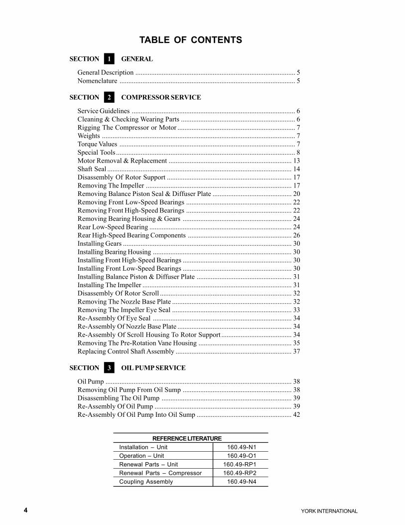
TABLE OF CONTENTS
SECTION 1 GENERAL
General Description ........................................................................................... 5Nomenclature .................................................................................................... 5
SECTION 2 COMPRESSOR SERVICE
Service Guidelines ............................................................................................. 6Cleaning & Checking Wearing Parts ................................................................. 6Rigging The Compressor or Motor ................................................................... 7Weights .............................................................................................................. 7Torque Values .................................................................................................... 7Special Tools ...................................................................................................... 8Motor Removal & Replacement ...................................................................... 13Shaft Seal ......................................................................................................... 14Disassembly Of Rotor Support ....................................................................... 17Removing The Impeller ................................................................................... 17Removing Balance Piston Seal & Diffuser Plate ............................................. 20Removing Front Low-Speed Bearings ............................................................ 22Removing Front High-Speed Bearings ............................................................ 22Removing Bearing Housing & Gears .............................................................. 24Rear Low-Speed Bearing ................................................................................. 24Rear High-Speed Bearing Components ........................................................... 26Installing Gears ................................................................................................ 30Installing Bearing Housing ............................................................................... 30Installing Front High-Speed Bearings .............................................................. 30Installing Front Low-Speed Bearings .............................................................. 30Installing Balance Piston & Diffuser Plate ...................................................... 31Installing The Impeller ..................................................................................... 31Disassembly Of Rotor Scroll ........................................................................... 32Removing The Nozzle Base Plate .................................................................... 32Removing The Impeller Eye Seal .................................................................... 33Re-Assembly Of Eye Seal ............................................................................... 34Re-Assembly Of Nozzle Base Plate ................................................................. 34Re-Assembly Of Scroll Housing To Rotor Support ........................................ 34Removing The Pre-Rotation Vane Housing ..................................................... 35Replacing Control Shaft Assembly .................................................................. 37
SECTION 3 OIL PUMP SERVICE
Oil Pump .......................................................................................................... 38Removing Oil Pump From Oil Sump .............................................................. 38Disassembling The Oil Pump .......................................................................... 39Re-Assembly Of Oil Pump .............................................................................. 39Re-Assembly Of Oil Pump Into Oil Sump ...................................................... 42
REFERENCE LITERATUREInstallation – Unit 160.49-N1Operation – Unit 160.49-O1Renewal Parts – Unit 160.49-RP1Renewal Parts – Compressor 160.49-RP2Coupling Assembly 160.49-N4

FORM 160.49-M1
5YORK INTERNATIONAL
SECTION 1GENERAL
GENERAL DESCRIPTION
These compressors are applied to YORK Model YKCentrifugal Liquid Chillers.
The compressor is a single-stage centrifugal type pow-ered by an open-drive electric motor. The casing is fullyaccessible with vertical circular joints and fabricated ofclose-grain cast iron. The complete operating assemblyis removable from the compressor scroll housing. Com-pressor castings are designed for 300 PSIG workingpressure and hydrostatically pressure tested at 900 PSIG.
The rotor assembly consists of a heat-treated alloy steeldrive shaft with a lightweight, high strength, cast alumi-num, fully shrouded impeller. The impeller is designedfor balanced thrust and is dynamically balanced andoverspeed tested for smooth, vibration-free operation.
The insert type journal bearings are fabricated of alu-minum alloy and are precision bored and axially grooved.Thrust bearings are of the deflection-pad type design.The specially engineered, single helical gears withcrowned teeth are designed so that more than one toothis in contact at all times to provide even distribution ofcompressor load and quiet operation. Gears are inte-grally assembled in the compressor rotor support andare film lubricated. Each shaft is individually mountedin its own journal and thrust bearings.
The open-drive compressor shaft seal consists of aspring-loaded, precision carbon ring, high-temperatureelastomer “O” ring static seal, and a stress-relieved,precision lapped collar. The seal features a small facearea and low rubbing speed. It provides an efficient sealunder high pressure conditions. The seal is oil-floodedat all times and is pressure-lubricated during compres-sor operation.
NOMENCLATURECOMPRESSOR IDENTIFICATION
Each compressor is identified by nomenclature as shown.The nomenclature is printed on a data plate which islocated on the side of the unit control panel. (See Fig. 1)
When contacting the factory or ordering renewal parts,include the complete compressor model and serial num-ber. Be sure these numbers are copied accurately.
29420A
YD H A 65
L H A 65Impeller Size - 36, 41, 46, 50, 57, 61, 65, 73, 81, 90Design Level (A - D)High Pressure Refrigerant CompressorOpen-DriveClose-Coupled D Flange Motor
YORK CODEPAK™®LIQUID CHILLING SYSTEM
UNIT MODEL
REFRIG. DWP. PSIG:
LIQUID DWP. PSIG:
NO. OF PASSES:
SHELL TEST PRESS. PSIG:
REFRIGERANT REFRIG. CHARGE LBS.
CHARGED: FACTORY FIELD
STARTER SUPPLIED BY: FACTORY FIELD
FIELD SUPPLY:
VOLTS PHASE HERTZ
MIN. CIRCUIT AMPACITY
MAX. DUAL ELEMENT FUSE AMPS
MAX. CIRCUIT BREAKER AMPS
COMPRESSOR: MODEL CODE
SERIAL NO.
HP VOLTS-PHASE-HZ FLA
OIL PUMP
CHARGE WITH YORK REFRIGERANT OILSEE STARTER NAMEPLATE AND CONTROLPANEL NAMEPLATE FOR ELECTRICAL DATA
COOLERCLG.
COND.H.R.
COND.
FOR REMOTE STARTER SEE YORK STD. R
LD04750
FIG. 1 – COMPRESSOR IDENTIFICATION
1
YORK INTERNATIONAL6
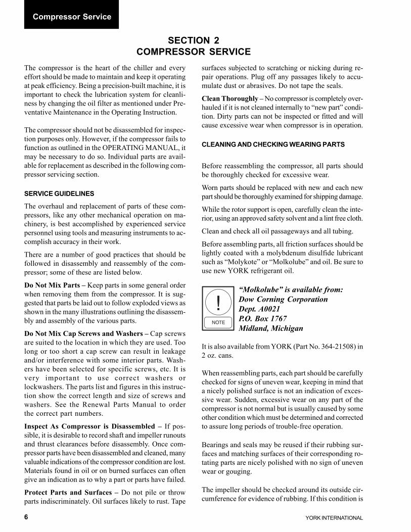
SECTION 2COMPRESSOR SERVICE
The compressor is the heart of the chiller and everyeffort should be made to maintain and keep it operatingat peak efficiency. Being a precision-built machine, it isimportant to check the lubrication system for cleanli-ness by changing the oil filter as mentioned under Pre-ventative Maintenance in the Operating Instruction.
The compressor should not be disassembled for inspec-tion purposes only. However, if the compressor fails tofunction as outlined in the OPERATING MANUAL, itmay be necessary to do so. Individual parts are avail-able for replacement as described in the following com-pressor servicing section.
SERVICE GUIDELINES
The overhaul and replacement of parts of these com-pressors, like any other mechanical operation on ma-chinery, is best accomplished by experienced servicepersonnel using tools and measuring instruments to ac-complish accuracy in their work.
There are a number of good practices that should befollowed in disassembly and reassembly of the com-pressor; some of these are listed below.
Do Not Mix Parts – Keep parts in some general orderwhen removing them from the compressor. It is sug-gested that parts be laid out to follow exploded views asshown in the many illustrations outlining the disassem-bly and assembly of the various parts.
Do Not Mix Cap Screws and Washers – Cap screwsare suited to the location in which they are used. Toolong or too short a cap screw can result in leakageand/or interference with some interior parts. Wash-ers have been selected for specific screws, etc. It isvery important to use correct washers orlockwashers. The parts list and figures in this instruc-tion show the correct length and size of screws andwashers. See the Renewal Parts Manual to orderthe correct part numbers.
Inspect As Compressor is Disassembled – If pos-sible, it is desirable to record shaft and impeller runoutsand thrust clearances before disassembly. Once com-pressor parts have been disassembled and cleaned, manyvaluable indications of the compressor condition are lost.Materials found in oil or on burned surfaces can oftengive an indication as to why a part or parts have failed.
Protect Parts and Surfaces – Do not pile or throwparts indiscriminately. Oil surfaces likely to rust. Tape
surfaces subjected to scratching or nicking during re-pair operations. Plug off any passages likely to accu-mulate dust or abrasives. Do not tape the seals.
Clean Thoroughly – No compressor is completely over-hauled if it is not cleaned internally to “new part” condi-tion. Dirty parts can not be inspected or fitted and willcause excessive wear when compressor is in operation.
CLEANING AND CHECKING WEARING PARTS
Before reassembling the compressor, all parts shouldbe thoroughly checked for excessive wear.
Worn parts should be replaced with new and each newpart should be thoroughly examined for shipping damage.
While the rotor support is open, carefully clean the inte-rior, using an approved safety solvent and a lint free cloth.
Clean and check all oil passageways and all tubing.
Before assembling parts, all friction surfaces should belightly coated with a molybdenum disulfide lubricantsuch as “Molykote” or “Molkolube” and oil. Be sure touse new YORK refrigerant oil.
“Molkolube” is available from:Dow Corning CorporationDept. A0021P.O. Box 1767Midland, Michigan
It is also available from YORK (Part No. 364-21508) in2 oz. cans.
When reassembling parts, each part should be carefullychecked for signs of uneven wear, keeping in mind thata nicely polished surface is not an indication of exces-sive wear. Sudden, excessive wear on any part of thecompressor is not normal but is usually caused by someother condition which must be determined and correctedto assure long periods of trouble-free operation.
Bearings and seals may be reused if their rubbing sur-faces and matching surfaces of their corresponding ro-tating parts are nicely polished with no sign of unevenwear or gouging.
The impeller should be checked around its outside cir-cumference for evidence of rubbing. If this condition is
Compressor Service

FORM 160.49-M1
7YORK INTERNATIONAL
found, excessive bearing wear is indicated, and the im-peller may be worn sufficiently to require replacement.All gaskets and “O” rings should be replaced with newwhen reassembling the compressor to assure that allsurfaces have a tight seal after reassembly.
RIGGING THE COMPRESSOR OR MOTOR
When it becomes necessary to remove a compressoror motor from a unit or base, proper rigging methods
must be used to avoid damage to the equipment and/orinjury to service personnel. Portable cranes must be ofadequate capacity and properly positioned and blockedto prevent tipping or slipping while lifting the compres-sor or motor. Be sure chains are of adequate strength.Compressor weights are shown in Fig. 2 – CompressorWeights (lbs.) – Less Motor. Motor weights are shownin Fig. 3 – Motor Weights (lbs.). 2
FIG. 3 – MOTOR WEIGHTS (LBS)
LOW VOLTAGEMOTOR CODE
60 HZ 50 HZ WEIGHTS
CH – 940CJ 5CE 940CK 5CF 1440CL 5CG 1440CM 5CH 1700CN 5CI 1700CP 5CJ 1700CR 5CK 1700CS 5CL 2635CT 5CM 2635CU 5CN 2635CV 5CO 2635CW 5CP 2930CX 5CQ 2930CY 5CR 2930CZ 5CS 2930CA 5CT 5750CB 5CU 5750DA 5CV 5750DB 5CW 6800DC 5CX 6800– 5DA 7300– 5DB 7300
HIGH VOLTAGEMOTOR CODE
60 HZ 50 HZ WEIGHTS
CH – 2670CJ 5CE 2670CK 5CF 3100CL 5CG 3100CM 5CH 3100CN 5CI 3100CP 5CJ 3700CR 5CK 3700CS 5CL 3700CT 5CM 3700CU 5CN 3700CV 5CO 4500CW 5CP 4500CX 5CQ 4500CY 5CR 4500CZ 5CS 4500CA 5CT 5800CB 5CU 5800DA 5CV 5800DB 5CW 6800DC 5CX 6800DD 5DA 7300DE 5DB 7300DF 5DC 7500DH 5DD 7500DJ 5DE 7900– 5DF 7900– 5DG 7900– 5DH 7900
FIG. 2 – COMPRESSOR WEIGHTS (LBS.) - LESS MOTORCOMPRESSOR COMPLETE ROTOR SUPPORT COMPLETE SCROLL ASSEMBLY
CODE COMPRESSOR WITH ALL RUNNING GEAR WITH PRV HOUSINGP1, P2, P3, P4 2,450 1,500 950
G4, H0, H1, H2, H3, H4, H5, H6, H7, H8 3,500 2,250 1,300J1 & J2 4,000 2,525 1,475J3 & J4 5,000 3,150 1,775
FIG. 4 – TORQUE VALUESBOLT SIZE TORQUE
INCHES POUND FOOTHEX HD 10
1/4" 12PT OR 14SOC HD3/8" 351/2" 855/8" 200**3/4" 300
Unless otherwise specified, all screws must be tightened to thetorque values at left with lightly oiled threads:
** Lubricated with oil and graphite on male and female threads andunder bolt heads. Molykote not acceptable.

YORK INTERNATIONAL8
Compressor Service
SPECIAL TOOLS
Special tools are available as an option and will be furnished when ordered. These tools are listed in Figs. 5, 7, 9, 11and 13. Use of the tools is shown in Fig. 6, 8, 10, 12 and 14.
FIG. 5 – COMPRESSOR TOOL KIT – 364K50048-000 (COMPRESSOR SIZES -39, -40, -42, -44)
FIG. 6 – USE OF COMPRESSOR TOOLS (-39, -40, -42, -44)
ITEM DESCRIPTION QTY. PART NO.NO. PER KIT1 GEAR LOCKING TOOL 1 364-502122 SCREW CAP HEX .375 -16 2 021-015113 WASHER PLAIN .375 14 021-012624 HEX NUT .375 - 16 2 021-004675 GUIDE PIN #10 - 24 2 064-464886 EYE BOLT .3125 - 18 2 021-124207 WASHER PLAIN .3125 16 021-051668 GUIDE PIN .250 - 20 2 064-464999 HOOK TOOL 2 064-46610
10 GUIDE PIN .375 - 16 2 064-1871611 STUD SPL .500 - 20 1 064-14500
12 HEX NUT .500 - 20 1 021-0048313 EYE BOLT .875 1 021-0770314 WASHER PLAIN .875 2 021-0515815 EYE BOLT .375 - 16 3 021-1349816 WASHER PLAIN .375 39 021-0516717 SPACER 1 064-5021318 SCREW CAP HEX .625 - 16 1 021-0838919 TOOL SPACER 1 364-5021020 PULLER TOOL 1 064-5021121 SCREW CAP HEX .500 - 20 1 021-1083222 SCREW CAP HEX .500 - 20 1 021-14162
ITEM DESCRIPTION QTY. PART NO.NO. PER KIT
LD06977

FORM 160.49-M1
9YORK INTERNATIONAL
2
LD04753
FIG. 8 – USE OF COMPRESSOR TOOLS (-64, -73, -81, -90)
FIG. 7 – COMPRESSOR TOOL KIT 364-48026 (COMPRESSOR SIZES -65, -73, -81, -90)
ITEM DESCRIPTION QTY. PART NO.NO. PER KIT12 HEX NUT - 1/2" HEAVY 1 021-0048313 EYEBOLT - 7/8" 1 021-0770314 WASHER, PLAIN - 7/8" 5 021-0515815 EYE BOLT - 3/8" 3 021-1349816 WASHER, PLAIN - 3/8" 11 021-0516717 EYE BOLT - 5/16" 2 021-1242018 WASHER, PLAIN - 5/16" 2 021-0516619 PINION TOOL (Mod. 65 & 73) 1 064-4802820 PINION TOOL (Mod. 50 & 57) 1 064-4802921 PIPE 1 023-15508
ITEM DESCRIPTION QTY. PART NO.NO. PER KIT1 GEAR LOCKING TOOL 1 364-480232 CAP SCREW - 5/8" 1 021-083893 SPACER TOOL 1 364-480224 CAP SCREW - 1/2" 2 021-083885 WASHER, PLAIN - 1/2" 2 021-012766 BAR TOOL 1 064-470317 HEX NUT - 1/4" 4 021-004518 GUIDE PIN 2 064-464999 HOOK TOOL 2 064-46610
10 GUIDE PIN 3 064-1871611 STUD 1 064-14500

YORK INTERNATIONAL10
FIG. 9 – COMPRESSOR TOOL KIT 364-49275 (COMPRESSOR SIZES -46, -50, -57, -59, -61)
FIG. 10 – USE OF COMPRESSOR TOOLS (-46, -50, -57, -59, -61)
LD04749
ITEM DESCRIPTION QTY. PART NO.NO. PER KIT1 GEAR LOCKING TOOL 1 364-480232 SCREW CAP HEX 1/2" 2 021-142493 WASHER PLAIN 17/32" 14 021-012764 NUT HEX HVY 1/2" 2 021-028605 PIN GUIDE 2 064-464886 BOLT EYE 5/16" 2 021-124207 WASHER PLAIN 11/32" 16 021-051668 PIN GUIDE 1/4-20UNC 2 064-46499
ITEM DESCRIPTION QTY. PART NO.NO. PER KIT9 HOOK TOOL 2 064-46610
10 PIN GUIDE 3/8" 2 064-1871611 STUD SPECIAL 1 064-1450012 NUT HEX HVY 1/2" 1 021-0048313 BOLT EYE 7/8" 1 021-0770314 WASHER PLAIN 15/16" 2 021-0515815 BOLT EYE 3/8" 3 021-1349816 WASHER PLAIN 13/32" 39 021-05167
Compressor Service

FORM 160.49-M1
11YORK INTERNATIONAL
FIG. 12 – USE OF COMPRESSOR TOOLS (-41)
FIG. 11 – COMPRESSOR TOOL KIT 364-48145 (COMPRESSOR SIZE -41)
ITEM DESCRIPTION QTY. PART NO.NO. PER KIT1 GEAR LOCKING TOOL 1 364-480232 SCREW CAP HEX - 5/8" 1 021-083893 TOOL SPACER 1 364-480224 SCREW CAP HEX 1/2" 2 021-083885 WASHER PLAIN 17/32" 2 021-012766 BAR TOOL 1 064-483457 NUT HEX 4 021-004518 PIN GUIDE 2 064-464999 HOOK TOOL 2 064-46610
10 PIN GUIDE 3/8" 3 064-1871611 STUD SPECIAL .500 1 064-14500
ITEM DESCRIPTION QTY. PART NO.NO. PER KIT12 NUT HEX HVY 1/2" 1 021-0048313 BOLT EYE 7/8" 1 021-0770314 WASHER PLAIN 15/16" 5 021-0515815 BOLT EYE 3/8" 3 021-1349816 WASHER PLAIN 13/32" 11 021-0516717 BOLT EYE 5/16" 2 021-1242018 WASHER PLAIN 11/32" 2 021-0516619 TOOL SPECIAL 1 064-4813323 SEAL O-RING 7/16" 1 028-1255125 ADAPTER 36-41 IMP 1 064-4828226 PULLER TOOL 36-44 IMP 1 064-48281
LD04651
2

YORK INTERNATIONAL12
FIG. 13 – COMPRESSOR TOOL KIT 364-48343 (COMPRESSOR SIZE -61)
ITEM DESCRIPTION QTY. PART NO.NO. PER KIT1 GEAR LOCKING TOOL 1 364-480232 SCREW CAP HEX - 5/8" 1 021-083893 TOOL SPACER 1 364-480224 SCREW CAP HEX 1/2" 2 021-083885 WASHER PLAIN 17/32" 2 021-012766 BAR TOOL 1 064-483457 NUT HEX 1/4" 4 021-004518 PIN GUIDE 1/4" 2 064-464999 HOOK TOOL 2 064-46610
10 PIN GUIDE 3/8" 3 064-18716
ITEM DESCRIPTION QTY. PART NO.NO. PER KIT11 STUD SPECIAL .500 1 064-1450012 NUT HEX HVY 1/2" 1 021-0048313 BOLT EYE 7/8" 1 021-0770314 WASHER PLAIN 15/16" 5 021-0515815 BOLT EYE 3/8" 3 021-1349816 WASHER PLAIN 13/32" 11 021-0516717 TOOL SPECIAL 1 064-4813318 SEAL O-RING 7/16" 1 028-1255120 ADAPTER IMPR 1 064-4831821 *I* PULLER TOOL 1 064-48342
FIG. 14 – USE OF COMPRESSOR TOOLS (-61)
LD04752
Compressor Service

FORM 160.49-M1
13YORK INTERNATIONAL
MOTOR REMOVAL AND REPLACEMENT
Be sure the main disconnect switch to the compressormotor is open and tagged, then disconnect the electricalleads at the motor terminals and tape the end of eachlead. Make sure leads are marked correctly for lateridentification.
REMOVAL (MOTOR ONLY)
The following paragraphs outline the procedure for re-placing or servicing the motor. Always contact the near-est YORK District Service Office when replacing orservicing the motor.
Close-Coupled Models1. Support the weight of the motor from a hoist using
eyebolts at locations provided in the motor housing.2. Remove the hex head cap screws that hold the sheet
metal covers to the compressor motor adapter. Af-ter all screws are removed, remove covers. (SeeFig. 15)
3. Remove the internal coupling guard. The internalcoupling guard is fastened to the compressor with(4) hex head cap screws. (See Fig. 16)
4. Remove the bolts holding the coupling hubs to thecoupling spool and the disc pack. Note arrangementof these parts. (See Fig. 17). Remove the couplingspool and disc packs.
5. Taking care to see that the motor is properly sup-ported, remove the bolts that hold the motor to themotor adapter.
6. Remove the bolts, nuts, and washers holding themotor to the mounting rails. Note location of anyshims.
7. Lift the motor and pull it away from the compres-sors. Lower motor to floor for servicing. Removeshims from motor mounting rails.
Open-Drive Models1. Remove the coupling guard. (See Fig. 18)2. Remove the bolts holding the coupling hubs to the
coupling spool and the disc pack. Note arrangementof these parts. (See Fig. 17). Remove the couplingspool and disc packs.
3. Remove the bolts, nuts and washers holding themotor to the mounting rails. Note location of anyshims.
4. Prior to performing Step 5, be sure to support theback end of the rotor support.
5. Taking care to see that the motor is properly sup-ported, remove the bolts that hold the motor to themotor adaptor.
6. Lift the motor and pull it away from the compres-sor. Lower motor to floor for servicing. Removeshims from motor mounting rails.
FIG. 15 – MOTOR ADAPTER
FIG. 16 – INTERNAL COUPLING GUARD
FIG. 17 – COMPRESSOR COUPLING
COVERMOTOR ADAPTER
25718A
LD04754
LD04755
2

YORK INTERNATIONAL14
INSTALLATION
Close-Coupled Models1. Place the number of shims originally required on
each motor mounting rail.2. Lift motor to the proper location and push motor
carefully against the compressor motor adapter.3. Line up holes in the face of the motor with the holes
in the compressor motor adapter. Place the hex headcap screws through the compressor motor adapterand screw into the tapped holes on the motor, (butdo not fully tighten screws). (See Fig. 15)
4. Place the hex head cap screws and washers in holesin motor feet. Make sure the motor is shimmed cor-rectly. Place hex nuts on screws and tighten andtorque.
5. Tighten and torque screws holding motor-to-motoradapter.
6. Assemble the coupling. Refer to Form 160.49-N4.
Open-Drive Models1. Place the number of shims originally required on
each motor mounting channel.2. Lift motor to its proper location on the motor mount-
ing channels. Fasten with cap screws, washers, andhex nuts.
3. Assemble the coupling. Refer to Form 160.49-N4.4. Re-assemble the coupling guard.
Before opening any part of thecompressor, the compressor must bepumped down to atmosphericpressure.
SHAFT SEALS
Shaft seals applied to these compressors are of two dif-ferent designs. Original design compressors used a car-bon ring cartridge type shaft seal. This design is shown inFigs. 19 - 23; procedures for removal and installation areshown on pages 14 & 15. Beginning approximately May1998, compressors are equipped with a bellows-type shaftseal. This seal is shown in Fig. 29; procedures for re-moval and installation are shown on pages 16 & 17.
Removal (Cartridge Type Seal)
To remove/replace the cartridge type shaft seal, pro-ceed as follows:1. Remove compressor coupling as described on pre-
vious pages under MOTOR REMOVAL ANDREPLACEMENT. Also remove the compressorcoupling hub from the compressor shaft.
2. Remove the oil drain line from the bottom of theshaft seal cover plate. (See Fig. 20)
3. Remove the (8) cap screws holding the cover plateand remove the cover plate. The stationary carbonseal will remain in the cover plate as it is removed.Do not touch the carbon seal surface.
4. Remove the snap ring and sleeve.5. Remove the seal cartridge assembly from the cover
plate. Do not disassemble the cartridge assembly.6. Using items from the tool kit as shown in Fig. 21
remove the seal collar from the shaft. (also see Figs.22 and 23)
COUPLING GUARD
26296A
FIG. 18 – COUPLING GUARD (OPEN-DRIVE MODELS)
CARBON SEALCARTRIDGEASSEMBLY(STATIONARY)
FIG. 19 – CARTRIDGE TYPE SHAFT SEAL CROSSSECTION
26439A
SLEEVE
SNAPRING
COVERPLATE
DRAIN TUBE
“O” RING
SEALCOLLAR
“O” RING
Compressor Service

FORM 160.49-M1
15YORK INTERNATIONAL
Installation (Cartridge Type Seal)1. Be sure the shaft seal cavity is absolutely clean by
cleaning it with an approved safety solvent and blow-ing it dry with compressed air.
2. Inspect all wearing surfaces and replace parts asnecessary. See “Cleaning And Checking Wear-ing Parts”, page 6. Discard all “O” rings and re-place with new.
3. Slide the seal collar onto the compressor shaft. Besure it is positioned with the lapped surface facingout. (See Fig. 22)
4. Re-install the cover plate and seal cartridge assem-bly. Use care so that the carbon seal is notdamaged.
5. Re-install the sleeve and secure it with the snapring.
6. Re-connect the oil drain line and re-install the com-pressor coupling if no further service is planned.
FIG. 23 – CARTRIDGE TYPE SHAFT SEALCOMPONENTS
“O” RING
SEALCOLLAR
CARBONSEAL
CARTRIDGE “O” RING
SNAPRING
RETAINERSLEEVE
SEALCOVERPLATE “O” RING
26349A
FIG. 20 – SHAFT SEAL COVER PLATE
FIG. 21 – SEAL REMOVAL
FIG. 22 – SEAL PLATE26350A
SEALCOLLAR
HOLES FOR PULLER RODS
LD04762
COVER PLATE DRAIN TUBE26354A
2

YORK INTERNATIONAL16
O-RING
SHAFT SEAL
Seal Removal (Bellows Type)
To remove/replace the bellows type shaft seal, proceedas follows:1. Remove compressor coupling as described on pre-
vious pages under MOTOR REMOVAL ANDREPLACEMENT. Also remove the compressorcoupling hub from the compressor shaft.
2. Remove the oil drain line.3. Loosen the two set screws (C) shown in Fig. 24.4. Remove the flat head screws and re-attach the re-
taining clips in the Installation position.
BELLOWS TYPE SEALS
There are 2 versions of the bellows typeshaft seals used on compressors manu-factured after May of 1998. One ver-sion is used on the HA and HB familyof compressors and the second versionis used on the HD and HF family ofcompressors. The HA and HB seal hasa separate sleeve spacer and C-ringthat needs to be manually inserted be-fore installing the seal assembly. TheHD and HF version have the sleevespacer and C-ring already installed inthe seal. Below are instructions onhow to remove and install these seals.
It is important that the shaft sealsleeve is securely attached to the com-pressor shaft prior to removal of theretaining clips. These clips protect theseal internals from harm during theassembly process and insure the properpositioning of the shaft seal for properseal face loading. Anytime a sealcartridge is outside the compressor, theretaining clips need to be in theirInstallation position.
5. Loosen the 4 set screws (B) shown in Fig. 24.6. Remove the 8 hex head screws holding the shaft
seal to the compressor housing.7. Using guide pins, carefully remove the seal assem-
bly from the rotor support.8. Remove the C-ring and sleeve spacer from com-
pressor shaft on HA and HB style compressors.9. Remove the O-ring from the rotor support housing.
Seal Installation (Bellows Type)1. Be sure the shaft seal cavity is absolutely clean by
cleaning it with an approved safety solvent and blow-ing it dry with compressed air.
2. Inspect all wearing surfaces and replace parts asnecessary. See “Cleaning And Checking Wear-ing Parts”, page 6. Discard all O-rings and replacewith new.
FIG. 24 – BELLOWS TYPE SHAFT SEAL
LD04759
Compressor Service

FORM 160.49-M1
17YORK INTERNATIONAL
3. Thoroughly lubricate shaft with clean YORK re-frigerant oil prior to installation. For HD and HFcompressors, proceed to Step 6.
4. Install the sleeve spacer on the shaft and slide it allthe way onto the shaft.
5. Thoroughly lubricate C-ring with clean YORK re-frigerant oil. Install the C-ring with the open side ofthe ring facing the compressor.
Care needs to be taken when install-ing the C-ring to prevent damage tothe ring on any burrs on the shaft oron the snap ring grove that may be onthe shaft of older compressors.
6. Install the shaft seal cover o-ring in the rotor sup-port housing.
7. Using guide studs install the seal cartridge in therotor support housing and secure it with the existing3/8" mounting screws.
8. Before tightening the shaft seal sleeve set screw,rotate the compress shaft to insure that the setscrews straddle the shaft keyway.
9. Without removing the two shaft seal sleeve retain-ing clips, tighten the four accessible set screws tothe compressor shaft.
10. Remove the retaining clips and tighten the remain-ing setscrews. Torque all six setscrews to 60 inchpounds. Install retaining clips in the Operating Posi-tion on seal face.
11. Re-connect the oil drain line and re-install the com-pressor coupling if no further service is planned.
DISASSEMBLY OF ROTOR SUPPORT
The following paragraphs outline the procedure for sepa-rating the rotor support from the rotor scroll if it be-comes necessary to service internal parts:
Removing the Rotor Supports from Rotor Scroll
For steps 1 thru 4 follow procedureslisted on previous pages of this in-struction.
1. Remove the compressor coupling.2. Remove all external piping from the rotor support.3. Using proper rigging techniques, temporarily sup-
port the weight of the back end of the rotor support.
4. Taking care that the motor is properly supported,remove the bolts that hold the motor to the motoradaptor. Remove the motor from the chiller and sitaway from work area. See “Motor Removal andReplacement” described on page 13. DO NOTremove the motor adaptor from the compressor.
5. Insert eyebolt into the top of the rotor support andusing proper rigging methods support the weight ofthe rotor support.
6. Remove (2) of the 12 point cap screws holding therotor support to the rotor scroll. Insert guide pins inplace of the (2) cap screws.
7. Loosen the remaining cap screws. Do not removethe (2) set screws/studs with nuts from the bottomof the flange near the drain pipe. Remove the nutsonly.
On the HF family of compressors itmay be necessary to temporarily rig asupport for the oil sump. The sumpson these compressors are not attachedto the shell.
8. Use (3) of the cap screws as jacking screws in thetapped holes provided to loosen the rotor supportfrom the rotor scroll. (See Fig. 25) Carefully pullthe rotor support out of the rotor scroll. Rotate theshaft by hand when removing the rotor support toprevent damage to the impeller inlet seal ring.
9. The rotor support can now be removed and restedon the end of the motor adapter.
REMOVING THE IMPELLER (size 46 & larger)(See Fig. 26)1. Before removing the impeller, measure and record
the following. (See Fig. 27) Position compressor sothat it is sitting on the correct horizontal plane toassure correct readings.
a. Impeller rim Runout (Design 0.003" max.)b. Impeller eye Runout (Design 0.002" max.)c. High Speed Axial thrust (Design 0.008"
to 0.021”)d. Low Speed Axial Thrust (Design 0.011"
to 0.019")2. Install the gear locking tool on the low-speed shaft.
(See Fig. 52)3. Remove the 3 (or 6) screws that hold the impeller
to the high-speed shaft. (See Fig. 28) Pull the im-peller from the high-speed shaft. Use care whenremoving the impeller so that the balance piston sealis not damaged.
2

YORK INTERNATIONAL18
FIG. 25 – DISASSEMBLY OF ROTOR SUPPORT FROM THE ROTOR SCROLL
ROTOR SUPPORTROTOR SCROLL
26439BA
FIG. 26 – IMPELLER AND BALANCE PISTON (IMPELLER SIZES 46 AND LARGER)
DIFFUSER PLATE
BALANCE PISTONRETAINER
SOCKET HEAD CAPSCREWS (3)
IMPELLER
CAP SCREWS (3 OR 6)
IMPELLER CLAMPING COLLAR
HIGH-SPEED SHAFT
BALANCE PISTON SEAL
COIL SPRINGS (8)
26439A
Compressor Service

FORM 160.49-M1
19YORK INTERNATIONAL
FIG. 27 – CHECKING IMPELLER TOLERANCES
DETAIL A – CHECKING RIM RUNOUT(TOLERANCE - .003")
26347A
DETAIL B – CHECKING EYE RUNOUT(TOLERANCE - .002")
26346A
DETAIL C – CHECKING AXIAL THRUST00588VIP
REMOVING THE IMPELLER(HA36 & HA41 Compressors) (See Figs. 29 & 30)1. Before removing the impeller, measure and record
the following: (See Fig. 27) Position compressor sothat it is sitting on the correct horizontal plane toassure correct readings.a. Impeller rim Runout (Design 0.003" Max.)b. Impeller eye Runout (Design 0.002" Max.)c. High Speed Axial thrust (Design 0.008"
to 0.021")d. Low Speed Axial Thrust (Design 0.011"
to 0.019")
FIG. 28 – REMOVING IMPELLER(IMPELLER SIZES 46 AND LARGER)
26345A
CAP SCREWS IMPELLERIMPELLER CLAMPING
COLLAR
FIG. 29 – IMPELLER MOUNTING(IMPELLER SIZES 36 & 41)
IMPELLER
IMPELLERCLAMPINGCOLLAR
CAP SCREWAND“O” RING
O-RING
26439A
2

YORK INTERNATIONAL20
REMOVING THE IMPELLER (HF COMPRESSORS)
1. Before removing the impeller, measure and recordthe following. (See Fig. 27) Position compressor sothat it is sitting on the correct horizontal plane toassure correct readingsa. Impeller rim Runout (Design 0.003" Maximum)b. Impeller eye Runout (Design 0.002" Maximum)c. High Speed Axial thrust (Design 0.009"
to 0.020")d. Low Speed Axial Thrust (Design 0.011"
to 0.019")
2. Install the gear locking tool on the low-speed shaft.(See Fig. 52)
3. Remove the cap screw from the impeller.Install Puller Plate and Puller Tool, found in the toolkit, onto the impeller. Apply a wrench to the pullerto remove the impeller clamping color.
Considerable torque will have to beapplied to the wrench in order to re-move the impeller-clamping collar.
REMOVING BALANCE PISTON SEAL AND DIFFUSERPLATE1. Remove the (3) socket head cap screws (shoulder
bolts) that fasten the balance piston retainer andbalance piston seal the to diffuser plate. (See Fig.32 and 33)
2. Remove (2) of the (6) cap screws that secure thediffuser plate to the bearing housing. Insert guidepins where cap screws were removed. Loosen the(4) remaining cap screws. (See Fig. 34) Insert jack-ing screws into holes to loosen diffuser plate frombearing housing.
3. Insert eyebolts from tool kit into jacking holes anduse proper rigging methods to lift diffuser plate fromcompressor. Also remove o-ring from back of dif-fuser plate.
Original design balance piston seal onHA, HB, and HD style compressorswere equipped with (8) coil springs.Current design on these compressorsuse (16) coil springs. On the HF stylecompressor the balance piston sealuses a flat spring washer in place ofthe coil springs. (See Fig. 35 - HF styleBalance Piston Seal Assembly)
2. Install the gear locking tool on the low-speed shaft.(See Fig. 52)
3. Remove the cap screw and O-ring from the impel-ler-clamping collar.
4. Mechanical Method – Install the adaptor and pullertool, found in the tool kit, as shown in Fig. 30. Applya wrench to the puller tools to remove the impellerclamping collar.
Considerable torque will have to beapplied to the wrench in order to re-move the impeller-clamping collar.
4a. Hydraulic Method – Install the hydraulic removaltool, found in the tool kit, as shown in Fig. 31. Con-nect a source of hydraulic pressure (5000 PSI mini-mum) to the head of the removal tool (1/8" NPT).Carefully and gradually apply hydraulic pressure untilthe clamping collar is loosened.
5. Pull the impeller from the high speed shaft. Usecare when removing the impeller so that the bal-ance piston seal is not damaged.
"O" RINGHYDRAULICTOOL
FIG. 31 – REMOVING THE IMPELLER(IMPELLER SIZES 36 & 41)
LD04761
ADAPTER
PULLER TOOL
FIG. 30 – REMOVING THE IMPELLER(IMPELLER SIZES 36 & 41)
LD04760
Compressor Service

FORM 160.49-M1
21YORK INTERNATIONAL
FIG. 33 – BALANCE PISTON SEAL (DISASSEMBLED)
26342A
DIFFUSER PLATE BALANCE PISTON RETAINER
COIL SPRINGS(See Note Above)
BALANCE PISTON SEAL
FIG. 32 – BALANCE PISTON SEAL26344A
DIFFUSERPLATE
BALANCEPISTON
SEAL
BALANCEPISTON
RETAINER
HIGH-SPEEDSHAFT
SOCKETHEAD CAP
SCREWS(SHOULDER
BOLTS)
FIG. 34 – REMOVING DIFFUSER PLATE26665A
TAPPED HOLES DIFFUSER PLATE
2
FIG. 35 – HF BALANCE PISTON SEAL ASSEMBLY
RETAINER PLATEFLAT SPRING
WASHERBALANCE
PISTON SEAL
00589VIP

YORK INTERNATIONAL22
REMOVING FRONT LOW-SPEED BEARINGS(SEE FIG. 36)1. Remove the (6) hex head cap screws that hold the
low-speed thrust bearing to the bearing housing, andusing (2) guide pins, remove the thrust bearing. Besure not to damage the bearing pads. (See Fig. 37& 38)
2. Before removing the low-speed thrust collar, mountan indicator as shown in Fig. 39 and check the runoutof the thrust collar. Maximum runout should notexceed .001" T.I.R. (It will be necessary to removethe shaft locking tool in order to take this measure-ment.)
3. Re-install the shaft locking tool. Remove the sockethead cap screws that hold the low-speed thrust col-lar to the low-speed shaft, and remove the thrustcollar. (See Fig. 40) Use care when handling sothat surfaces are not damaged.
4. To remove the low-speed bearing, use (2) hook toolsas shown in Fig. 41. Carefully pull the bearing outof the bearing housing. Note the position of roll pin.(See Fig. 42)
On the HF style compressors all lowand high speed bearings use o-ringson the outside diameter of the bear-ing. These o-rings should be discardedand new o-rings installed when reas-sembling compressor.
REMOVING FRONT HIGH-SPEED BEARINGS(SEE FIG. 36)
1. Remove the cap screw and retainer clip. (Fig. 42)2. Using (2) 1/4" puller rods as shown in Fig. 43, pull
the high-speed bearing out of the bearing housing.
FIG. 36 – FRONT BEARING COMPONENTS
FIG. 37 – LOW-SPEED THRUST BEARING
LOW-SPEEDTHRUSTBEARING
26335A
26334A
LOW-SPEEDTHRUSTBEARING(INSIDESURFACE,MAY BEFURNISHEDWITH 4 OR 6PADS)
FIG. 38 – LOW-SPEED THRUST BEARING REMOVED
BEARINGHOUSING
26439A
FRONT HIGH-SPEEDBEARING
HIGH-SPEEDSHAFT
BEARING RETAINERCLIP WITH CAP SCREW
ROLL PIN
LOW-SPEEDTHRUST COLLAR
LOW-SPEED SHAFT
FRONT LOW-SPEEDBEARING
LOW-SPEEDTHRUST BEARING
Compressor Service

FORM 160.49-M1
23YORK INTERNATIONAL
FIG. 39 – CHECKING LOW-SPEED THRUST RUNOUT
26333A
LOW-SPEEDTHRUSTCOLLAR
FIG. 40 – LOW-SPEED THRUST COLLAR REMOVED
LD04837
FIG. 41 – FRONT LOW-SPEED BEARING REMOVAL
LD04836
FIG. 43 – FRONT HIGH-SPEED BEARING REMOVAL
FIG. 44 – ALL FRONT END BEARING REMOVED26329A
LOW-SPEEDBEARING
LOW-SPEEDTHRUST BEARING(INSIDE SURFACE)
26332A
FRONTHIGH-SPEEDBEARING
RETAINERCLIP WITHCAP SCREW
ROLL PIN
LOW-SPEEDSHAFT
26330A
FIG. 42 – LOW-SPEED BEARING REMOVED WITHHIGH-SPEED BEARING IN PLACE
2

YORK INTERNATIONAL24
REMOVING BEARING HOUSING AND GEARSBearing Housing1. Remove (2) of the cap screws that hold the bearing
housing to the rotor support and insert (2) 3/8" guidepins as shown in Fig. 45. Also insert (3) 3/8" eye-bolts as shown. On the HF style compressors, the(2) 1/2" cap screws shown in Fig. 46 are used tosecure the dowel pins which align the bearing hous-ing with rotor support. Remove dowel pins.
2. Attach proper rigging, and remove the remainingcap screws.
Remove the bearing housing, usingcare so that the compressor is notdamaged and that no injury occurs toservice personnel as the bearing hous-ing is quite heavy.
Gears1. Remove the high-speed reverse thrust bearing, high-
speed thrust collar, and high-speed forward thrustbearing.
2. Remove the shaft locking tool.3. Remove the compressor shaft seal. DO NOT re-
move the rear low-speed bearing.4. Rotate the high-speed gear as necessary to free
the gear teeth while pulling the gear from the rotorsupport.
5. To remove the low-speed gear, use a 1/2" - 13 eye-bolt in the end of the shaft and pull the gear out ofthe rotor support.Before re-assembly, be sure the compressor hous-ing is absolutely clean by cleaning it with an ap-proved safety solvent and blowing it dry with com-pressed air. Inspect all wearing surfaces and re-place parts as necessary. See “Cleaning AndChecking Wearing Parts”, page 6. Discard “O”rings and replace with new.
REAR LOW-SPEED BEARING(SEE FIG. 47)Removal
To remove/replace the rear low-speed bearing, proceedas follows:1. Remove the compressor coupling spool as described
on previous pages under “Motor Removal AndReplacement”. Also remove the compressor hubfrom the compressor shaft.
2. Remove the compressor shaft seal as described onprevious pages.
3. Remove the screw holding the retainer clip to thecompressor.
4. Using the (2) 1/4" puller rods as shown in Fig. 48,remove the bearing from the compressor.
5. Inspect the bearing. See “Cleaning And Check-ing Wearing Parts”, page 6. Replace with newbearing if necessary.
EYEBOLTS
GUIDE PINS
DOWEL PINS
EYEBOLT
26329A
FIG. 45 – REMOVING BEARING HOUSING
Compressor Service
FIG. 46 – HF BEARING HOUSING DOWEL PINS
00590VIP
DOWEL PINSLOCATED UNDER
1/2" CAP SCREWS

FORM 160.49-M1
25YORK INTERNATIONAL
CARTRIDGE TYPE SEAL BELLOWS TYPE SEAL
29370AE
RETAINERCLIP & SCREW
PULLERHOLE
BEARING
26326A
29439A
RETAINER CLIP
REAR LOW SPEEDBEARING
FIG. 47 – REAR LOW-SPEED BEARING
26323A
PULLER HOLES
RETAINER CLIP
LD04838
FIG. 48 – LOW-SPEED REAR BEARING REMOVAL
Installation1. Inspect the bearing surface of the drive shaft, and
be sure the drive shaft is absolutely clean.2. Apply a light coat of oil and Molykote to the crank-
shaft and to the inside and outside surfaces of thebearing.
3. Carefully slide the bearing into position over the driveshaft. Be sure it is turned so that the slot for theretainer clip is at the top. (See Fig. 47)
4. Install the retainer clip and cap screw.5. Install the shaft seal and coupling following proce-
dures outlined previously in this manual.
2

YORK INTERNATIONAL26
REAR HIGH-SPEED BEARING COMPONENTS
Rear High-Speed Bearings are of 2slightly different designs.• The original design, shown in Fig.
49, is applicable to G, HA and HBcompressors.
• The second design shown in Fig. 59is applicable to HD and HF designlevels.
• (Refer to Compressor Codes in tableon front cover, and Nomenclature onpage 5).
To remove/replace any of the components shown in Fig.49, proceed as follows:1. Remove the Proximity Probe.2. Remove the cap screws holding the high-speed re-
verse thrust bearing and remove the bearing. (SeeFig. 50). Note alignment of oil passages.
3. Before removing the high-speed thrust collar, it isadvisable to measure the run-out on the collar face.Mount a dial indicator as shown in Fig. 51 and ro-tate the compressor shaft to record run-out. Maxi-mum run-out is .001".
4. To remove the high-speed thrust collar, it is neces-sary to lock the shafts using the gear locking toolfrom the tool kit. (See Fig. 52)
5. Remove the cap screws that hold the high-speedthrust collar to the high-speed shaft. (See Fig. 53).Remove the thrust collar. (1/4"-20 puller holes areprovided for convenience.)
6. Remove the high-speed forward thrust bearing. (SeeFig. 54). #10-24 puller holes are provided for con-venience. When inserting puller bolts, use care thatbearing pads are not damaged. Note position of in-dexing roll pin and mating hole in casing. (See Fig.55)
7. Remove the cap screw holding the high-speed bear-ing retainer clip to the casing. (See Fig. 56). Usingitems from the tool kit as shown in Fig. 57, removethe bearing from the compressor.
8. Inspect all parts removed above. See “CleaningAnd Checking Parts”, page 6. Replace with newparts as necessary.
PROXIMITYPROBE LOCATION(NOT SHOWN)
HIGH-SPEEDREVERSETHRUST BEARING
26664A
26662A
HIGH-SPEEDREVERSETHRUST BEARING(INSIDE SURFACE)
FIG. 50 – HIGH-SPEED REVERSE THRUST BEARING
RETAINER“O” RING
HIGH-SPEEDFORWARDTHRUSTBEARING
HIGH-SPEEDTHRUSTCOLLAR
HIGH-SPEEDREVERSETHRUSTBEARING
HIGH-SPEEDBEARING(REAR)
29439A
FIG. 49 – HIGH-SPEED BEARING COMPONENTS -REAR (H COMPRESSORS - DESIGNLEVELS A, B, & C; J COMPRESSORS)
Compressor Service

FORM 160.49-M1
27YORK INTERNATIONAL
HIGH-SPEEDTHRUST COLLAR
26663A
FIG. 51 – CHECKING HIGH-SPEED THRUSTCOLLAR RUN-OUT
FIG. 52 – GEAR LOCKINGLD04839
FIG. 53 – HIGH-SPEED THRUST COLLAR REMOVED26339A
HIGH-SPEEDFORWARDTHRUSTBEARING
HIGH-SPEEDTHRUSTCOLLAR
INSIDESURFACE
PULLERHOLES(#10-24)
FORWARDTHRUSTBEARING
26338A
FIG. 54 – HIGH-SPEED FORWARD THRUST BEARING
ROLL PINHOLE
FORWARDTHRUSTBEARING
ROLL-PIN
26337A
FIG. 55 – FORWARD THRUST BEARING REMOVED
PULLER HOLES(1/4")
RETAINER CLIPWITH SCREW
26336A
FIG. 56 – REAR HIGH-SPEED JOURNAL BEARING
2

YORK INTERNATIONAL28
REAR HIGH-SPEED BEARINGS REMOVAL –HD AND HF COMPRESSORS
To remove/replace any of the components shown in Fig.59, proceed as follows:
1. Remove the Proximity Probe or Pressure Switchassembly.
On HF style compressors the Proxim-ity Probe has been replace with a pres-sure switch. (See Fig. 60). This pres-sure switch is installed on a brass tubethat has its tip protruding into agroove on the High Speed Thrust Col-lar. If the thrust tolerance exceeds adetermined distance, the sacrificialbrass tip will wear through, pressur-ize the tube with oil and trip the pres-sure switch to shut down the chiller.
2. Remove the cap screws holding the high-speed re-verse thrust bearing and remove the bearing. (SeeFig. 50). Note alignment of oil passages.
3. Before removing the high-speed thrust collar, it isadvisable to measure the run-out on the collar face.Mount a dial indicator as shown in Fig. 51 and ro-tate the compressor shaft to record run-out. Maxi-mum run-out is .001”.
4. To remove the high-speed thrust collar, it is neces-sary to lock the shafts using the gear locking toolfrom the tool kit. (See Fig. 52)
FIG. 57 – HIGH-SPEED REAR BEARING REMOVAL
LD04840
FIG. 58 – HIGH-SPEED BEARING COMPONENTS -REAR (G, HA & HB COMPRESSORS)
00280VIP
FIG. 59 – HIGH-SPEED BEARING COMPONENTS -REAR (HD & HF COMPRESSORS)
00281VIP
Compressor Service

FORM 160.49-M1
29YORK INTERNATIONAL
5. Remove the cap screws that hold the high-speedthrust collar to the high-speed shaft. (See Fig. 53).Remove the thrust collar. (1/4” – 20 puller holesare provide for convenience)
6. Loosen but do not remove the (3) hex socket headcap screws that hold the high-speed forward thrustbearing to the high-speed bearing.
7. Use the #10-24 puller rods to pull the high-speedforward thrust bearing and high-speed bearing fromthe compressor.
8. Inspect all parts removed above. See “CleaningAnd Checking Parts”, page 6. Replace with newparts as necessary.
REAR HIGH-SPEED BEARINGS INSTALLATION – GAND H COMPRESSOR DESIGN LEVELS A, B, &C ANDALL J COMPRESSORS
1. Be sure the bearing surface of the high-speed shaftis clean and is in good condition.
2. Apply a light coating of oil and Molykote to the high-speed shaft and to the inside and outside surfacesof the rear high-speed bearing.
3. Carefully slide the high-speed bearing with the bear-ing retainer clip into position. Insert cap screw intothe retainer clip and tighten.
4. Apply a light coating of oil and Molykote to the in-side diameter and pads of the forward thrust bear-ing. Reinstall the forward thrust bearing taking carethat the roll pin enters the hole in the compressorcasing. (See Fig. 55)
5. Apply a light coating of oil and Molykote to bothsides of the thrust collar. Install the thrust collar andtighten (4) hex socket cap screws to the high-speedshaft. Check run-out of shaft collar. Maximum run-out is .001".
6. Apply a light coating of oil and Molykote to the padsof the high-speed reverse thrust bearing. Install re-verse thrust bearing using a new o-ring. Be sure oilpassages in the bearing line up with the oil passagesin the compressor casing.
7. Re-install the Proximity Probe.
After reinstalling the ProximityProbe, a Calibration Procedure,as outlined in Form 160.49-M2, mustbe performed before restarting thecompressor.
REAR HIGH-SPEED BEARINGS INSTALLATION – HDAND HF COMPRESSORS
1. Be sure the bearing surface of the high-speed shaftis clean and is in good condition.
2. Apply a light coating of oil and Molykote to the high-speed shaft and to the inside and outside surfacesof the rear high-speed bearing. On HF style com-pressors install new o-ring on high-speed bearing.
3. Apply a light coating of oil and Molykote to theinside diameter and pads of the forward thrustbearing.
4. Insert but do not tighten the (3) hex head socketscrews that hold the high-speed forward thrust bear-ing to the high-speed bearing.
5. Carefully slide the high-speed bearing and high-speed forward thrust bearing into position. Be surethe roll pin on the forward thrust bearing enters thehole in the compressor casing. Tighten the (3) capscrews that secure the forward thrust bearing tothe high-speed bearing.
6. Apply a light coating of oil and Molykote to bothsides of the thrust collar. Install the thrust collar andtighten the (4) hex socket cap screws to the high-speed shaft. Check run-out of shaft collar. Maxi-mum run-out is .001".
7. Apply a light coating of oil and Molykote to the padsof the high-speed reverse thrust bearing. Install re-verse thrust bearing using a new o-ring. Be sure oilpassages in the bearing line up with the oil passagesin the compressor casing.
2
FIG. 60 – HF PROXIMITY SWITCH
PROXIMITYPRESSURESWITCH
BRASSTUBE
00591VIP

YORK INTERNATIONAL30
INSTALLING GEARS1. Oil the bearing surfaces on the drive end of the
low-speed gear, and carefully insert the low-speedgear into the rear bearing.
2. Oil the rear bearing surface on the high-speed shaft,and insert it into the rear bearing. Mesh the high-speed and low-speed gear teeth and rotate the gearsas the gear is installed.
3. Check the clearance between the high-speed gearand the spray header. Clearance should be 0.12"min./ 0.18" max. Adjust if necessary.
INSTALLING BEARING HOUSING1. Install a new o-ring in the groove around the oil
reservoir cavity. (See Fig. 61). Coat the o-ring witha suitable o-ring lubricant to hold it in the groove.
2. Insert (2) guide pins 180 degrees apart into the ro-tor support.
3. Lift the bearing housing and carefully push in placeover the guide pins. Note location of dowel pins. Be
careful not to damage any of the machined sur-faces on either the high-speed or low-speed shafts.Leave the guide pins in position to help support thebearing housing.
4. Install the cap screws and dowel pins. Tighten capscrews to proper torque as outlined in Table 4. OnHF style compressors install the (2) ½" cap screwsused to secure the dowel pins as shown in Fig. 42A.
INSTALLING FRONT HIGH-SPEED BEARINGS(SEE FIG. 36)1. Apply a coating of oil and Molykote to the bearing
surfaces of the high-speed shaft.2. Apply a coating of oil and Molykote to the inside
and outside surfaces of the high-speed bearing.3. Carefully slide the high-speed bearing into place over
the shaft and into the cavity in the bearing housing.Install the retainer clip and cap screw.
INSTALLING FRONT LOW-SPEED BEARINGS1. Apply a coating of oil and Molykote to the bearing
surface of the low-speed shaft.2. Apply a coating of oil and Molykote to the inside
and outside surfaces of the low-speed bearing.3. Carefully slide the low-speed bearing into place over
the shaft and into the cavity in the bearing housing.Be sure hole in bearing flange engages roll-pin inbearing housing. (See Fig. 42)
4. Re-install the shaft locking tool.5. Apply a coating of oil and Molykote to the lapped
surfaces of the low-speed thrust collar, using carethat no damage occurs. Place the thrust collarinto position on the end of the low-speed shaft,insert cap screws, and tighten to proper torque.(See Table 4)
6. Mount a dial indicator as shown in Fig. 39 and checkthe run-out of the thrust collar. (It will be necessaryto remove the shaft locking tool to take this mea-surement) Maximum run-out should not exceed.001" T.I.R. If run-out exceeds .001"T.I.R. DO NOTproceed with further assembly; contact the YORKFactory Service Department for assistance.
7. Re-install the shaft locking tool.8. Apply a coating of oil and Molykote to the bearing
pads of the low-speed thrust bearing and to thelow-speed thrust collar. Install the low-speed thrustbearing.
FIG. 61 – BEARING HOUSING
CHECK VALVE
OILRESERVOIR
“O” RING
26328A
8. Re-install the Proximity Probe or Pressure Switchassembly.
After reinstalling the Proximity Probeon the HD style compressor, a Cali-bration Procedure, as outlined inForm 160.49-M2, must be performedbefore restarting.
Compressor Service

FORM 160.49-M1
31YORK INTERNATIONAL
INSTALLING BALANCE PISTON ANDDIFFUSER PLATE1. Install a new O-ring on the diffuser plate.2. Insert (2) ¼" diameter guide pins into the rotor sup-
port.3. Using proper rigging methods, slide the diffuser plate
over the guide pins and into position against the ro-tor support. (See Fig. 34)
4. Insert (4) of the bolts before removing rigging andguide pins; then insert remaining bolts and tighten.
5. On the HF style compressor, install that flat springonto the balance piston seal. On all other style com-pressors, install the (8) or (16) helical springs, largeend first, into the balance piston seal. Rotate eachspring to lock it into place. (See Fig. 33)
6. Apply Loctite and insert the (3) cap screws andfasten the balance piston seal and balance pistonretainer to the diffuser plate.
7. After tightening the (3) cap screw, check that thebalance piston seal is free to “float”.
INSTALLING THE IMPELLERImpeller Sizes 46 and Larger1. Re-install the shaft locking tool.2. Apply a light coating of oil and Molykote to the in-
side diameter of the balance piston seal.3. Slide impeller into position on the high-speed shaft
using care not to damage the balance piston seal.4. Install the impeller clamping collar and the (3) or
(6) cap screws onto the high speed shaft.5. Torque cap screws to 120 ft. lbs. in (2) equal steps.
Refer to Fig. 62 for sequence of tightening screws.6. Remove the shaft locking tool and check rim and
eye radial runout using a dial indicator. (See Fig.27). Maximum runout on rim is .003" and runout oneye is .002". If T.I.R. deviates from specification,
increase torque to 150 ft. lbs. Maximum to the boltsopposite to the high side. Repeat as necessary untilallowable T.I.R. is achieved.
7. Check high-speed thrust clearance. Acceptablethrust tolerance is between .008" to .021".
8. Check low-speed thrust clearance. Acceptablethrust tolerance is between .011" to .019" Note thatthis measurement must be taken with the shaft sealinstalled.
Impeller for HA36 and HA411. Re-install the shaft locking tool.2. Apply a light coating of oil and Molykote to the in-
side diameter of the balance piston seal.3. Install O-ring in impeller and install on the high-speed
shaft using care not to damage the balance pistonseal.
4. Install O-ring on impeller clamping collar and installin impeller bore over high-speed shaft. MAKEABSOLUTELY CERTAIN THAT O-RINGSARE IN PLACE PRIOR TO INSTALLINGAND TORQUING CAP SCREW.
5. Torque cap screw to 120 ft. lbs.6. Remove the shaft locking tool and check rim and
eye radial runout using a dial indicator. (See Fig.27). Maximum runout on rim is .003" and runout oneye is .002".
7. Check high-speed thrust clearance. Acceptablethrust tolerance is between .008" to .021".
8. Check low-speed thrust clearance. Acceptablethrust tolerance is between .011" to .019". Note thatthis measurement must be taken with the shaft sealinstalled.
Impeller for HF Compressors1. Re-install the shaft locking tool.2. Apply a light coating of oil and Molykote to the in-
side diameter of the balance piston seal.3. Install impeller and clamping collar on high-speed
shaft.4. Torque cap screw to 90 ft. lbs.
FIG. 62 – IMPELLER MOUNTING SCREWSTIGHTENING SEQUENCE
LD05188
PERMISSIBLE RUNOUT OF IMPELLERIMPELLER DIA. RIM EYE
(INCHES) RADIAL RADIAL
11.30, 10.00 .003 .002
2
YORK INTERNATIONAL32
5. Remove the shaft locking tool and check rim andeye radial runout using a dial indicator. (See Fig.27). Maximum runout on rim is .003" and runout oneye is .002".
6. Check high-speed thrust clearance. Acceptablethrust tolerance is between .009" to .020".
7. Check low-speed thrust clearance. Acceptablethrust tolerance is between .011" to .019". Note thatthis measurement must be taken with the shaft sealinstalled.
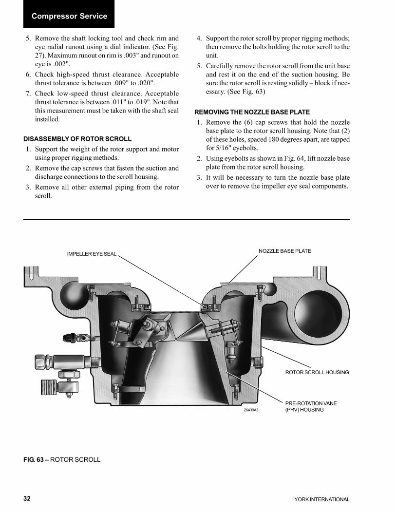
DISASSEMBLY OF ROTOR SCROLL1. Support the weight of the rotor support and motor
using proper rigging methods.2. Remove the cap screws that fasten the suction and
discharge connections to the scroll housing.3. Remove all other external piping from the rotor
scroll.
4. Support the rotor scroll by proper rigging methods;then remove the bolts holding the rotor scroll to theunit.
5. Carefully remove the rotor scroll from the unit baseand rest it on the end of the suction housing. Besure the rotor scroll is resting solidly – block if nec-essary. (See Fig. 63)
REMOVING THE NOZZLE BASE PLATE1. Remove the (6) cap screws that hold the nozzle
base plate to the rotor scroll housing. Note that (2)of these holes, spaced 180 degrees apart, are tappedfor 5/16" eyebolts.
2. Using eyebolts as shown in Fig. 64, lift nozzle baseplate from the rotor scroll housing.
3. It will be necessary to turn the nozzle base plateover to remove the impeller eye seal components.
FIG. 63 – ROTOR SCROLL
26439A3PRE-ROTATION VANE(PRV) HOUSING
ROTOR SCROLL HOUSING
NOZZLE BASE PLATEIMPELLER EYE SEAL
Compressor Service

FORM 160.49-M1
33YORK INTERNATIONAL
FIG. 65 – NOZZLE BASE PLATE WITH IMPELLER EYE SEAL IN PLACE
26302A
CAP SCREWS
EYE SEALRETAINER
“O” RING
NOZZLEBASE PLATE
REMOVING THE IMPELLER EYE SEAL1. Remove the cap screws that hold the eye seal re-
tainer to the nozzle base plate. (See Fig. 65)2. Remove the eye seal retainer and the eye seal ring
from the nozzle base plate. (See Fig. 66)
The Pre-Rotation Vane Assembly can-not be removed from the suction con-nection side of the compressor on theHA, HB and HD style compressors. Itmust be removed from the inside of therotor scroll housing AFTER thenozzle base plate is removed. If disas-sembly of the PRV housing is antici-pated on these compressors, proceed to“Removing the Pre-Rotation VaneHousing” on page 35. Otherwise, pro-ceed with re-assembly of the compres-sor as follows.
FIG. 64 – LIFTING NOZZLE BASE PLATE
LD05190
“O” RING
FIG. 66 – EYE SEAL COMPONENTS 26301A
ROLL PIN
HOLEFOR
ROLL PIN
HELICALSPRINGS
EYESEAL RING
EYE SEALRETAINER
2

YORK INTERNATIONAL34
RE-ASSEMBLY OF NOZZLE BASE PLATE1. 1. Install a new o-ring on the nozzle base plate.
(See Fig. 65)2. Carefully turn the nozzle base plate over and insert
eyebolts into the (2) tapped holes.3. Insert guide pins into (2) of the holes in the scroll
housing.4. Using proper rigging methods, lower the nozzle base
plate over the guide pins and into position in thescroll housing. Remove eyebolts and guide pins; in-sert cap screws and tighten to specified torque inTable 4.
RE-ASSEMBLY OF SCROLL HOUSINGTO ROTOR SUPPORT1. Using proper rigging methods, lift scroll housing as-
sembly into place on unit base.2. Using new gaskets, re-connect suction and dis-
charge piping.3. Insert guide pins into the scroll housing and install a
new gasket. Note that the gasket contains threeholes to clear the jacking screws in the rotor sup-port. Be sure gasket is installed correctly. (See Fig.68). Coat gasket with a mixture of oil and graphite.
On the HF style compressors this seal-ing surface uses an o-ring instead of agasket. Coat the o-ring with a suitableo-ring lubricant to secure o-ring intogroove during assembly.
RE-ASSEMBLY OF THE EYE SEAL(HA, HB, HD Style Compressors)1. Inspect all parts before re-assembly. See “Clean-
ing and Checking Wearing Parts”, page 6. Re-place with new parts as necessary.
2. Be sure the helical springs are securely locked inpockets. Give each spring a clockwise twist to lockit into place. Install a new o-ring in the eye sealretainer.
3. Place the eye seal ring and retainer into position onthe nozzle base plate. Be sure the hole in the eyeseal ring fits over the roll pin in the nozzle base plate.(See Fig. 66). Insert cap screws and tighten. Checkthat the seal ring is free to “float”.
(HF Style Compressors)
This style compressor uses a flat springwasher instead of the helical springsused on the HA, HB, and HD stylecompressors. (See Fig. 65 – HF EyeSeal)
1. Inspect all parts before re-assembly. See “Clean-ing and Checking Wearing Parts”, page 6. Re-place with new parts as necessary.
2. Place flat spring washer into retainer and positioneye seal over spring washer.
3. Take complete eye seal assembly and position onnozzle base plate. Insert cap screws and tighten.Check that seal ring is free to “float”.
FIG. 68 – SCROLL HOUSING READY FORRE-ASSEMBLY TO MOTOR SUPPORT
26301A
CLEARANCEHOLES FORJACKING SCREWS
FIG. 67 – HF EYE SEAL
Compressor Service
00592VIP
IMPELLER EYESEAL RETAINER
FLAT SPRINGWASHER IMPELLER
EYE SEAL

FORM 160.49-M1
35YORK INTERNATIONAL
4. Apply a light coating of oil and Molykote onto theeye of the impeller where it enters the eye seal ring.
5. Using proper rigging methods, raise the rotor sup-port with motor adapter into proper position, andslide it into place over the guide pins.
6. Carefully slide the rotor support into place againstthe scroll housing. Use care that the impeller is notdamaged as it enters the eye seal ring.
7. Insert the cap screws and tighten to the propertorque. (See Table 4)
8. Re-install the compressor coupling.9. Bolt the motor to the motor adaptor.
10. Re-connect all external piping.
REMOVING THE PRE-ROTATION VANE HOUSING
The Pre-Rotation Vane Assembly cannot be removedfrom the suction connection side of the compressor onthe HA, HB and HD style compressors. The rotor sup-port must first be removed from the rotor scroll and therotor scroll dissembled as described previously.
On the HF style compressor, access to the PRV assem-bly can be made by removing the suction piping and re-moving the cap screws that secure the PRV plate sup-port to the rotor scroll. Insert proper guide pins and usingproper rigging methods, remove PRV support plate fromcompressor scroll to gain access to the PRV assembly.(See Fig. 69)
FIG. 71 – PRE-ROTATION VANEHOUSING ASSEMBLY
26667A
LD05191
ITEM DESCRIPTION QTY. ITEM DESCRIPTION QTY.NO. NO.1 Ring, Driving 1 7 Washer 102 Vane 9 8 Stud, Ball 93 Retainer 9 9 Screw – 12 pt. 94 Arm, Vane 9 10 Screw – Hex HD 185 Spacer, Arm 9 11 Nut, Self-Locking 96 Washer 9 12 Housing 1
2
FIG. 70 – INTERNAL PARTS - PRE-ROTATIONVANE ASSEMBLY 26666A
PRE-ROTATIONVANE DRIVING RING
INTERNAL LEVER
FIG. 69 – REMOVING HF PRV SUPPORT PLATE
00593VIP
GUIDE PINPRV SUPPORTPLATE

YORK INTERNATIONAL36
FIG. 72 – PRE-ROTATION VANE ASSEMBLY
21501
3 10
5 46
9
11(7, 12)*
810
2
After access is made to the PRV assembly proceed asfollows:1. Remove the 12 pt. Hd. cap screw and fill piece to
disconnect the adjustable bearing rod from the vanedriving ring. (See Fig. 70)
2. Remove the (2) hex hd. cap screws at approximately180 degrees apart. Replace these screws with (2)guide pins from the tool kit. Then remove the re-maining screws from around the perimeter of thePRV assembly. Hook a lifting device to the assem-bly and carefully pull off the guide studs and placeon a work bench to replace any parts.
3. The PRV vanes are actuated by a rotating vanedrive ring through individual vane arms to each vane.
Individual vanes may be removed bya. unscrewing the cap screw which secures the
vane arm to the vane;b. lifting off the vane arm;c. lifting off the two special washers and pulling
the vane out toward the inside of the vanehousing. (Refer to Fig. 71)
4. If any of the individual vanes were removed orreplaced, refer to Figs. 71 and 72. The vane capscrew must be tightened to the torque as indicatedin Table 4.
5. Re-assembly the PRV assembly and the nozzle baseplate together in reverse order. Torque all screws inaccordance with Table 4.
Compressor Service

FORM 160.49-M1
37YORK INTERNATIONAL
REPLACING CONTROL SHAFT ASSEMBLY
The external and internal levers are secured to the con-trol shaft by means of a single 12 pt. Hd. cap screwthreaded into the internal lever. (Refer to Fig. 73). Ad-justable stops are provided in the internal lever arm.These stops ARE NOT to be used to stop the vanes inthe extreme positions of normal travel, but are suppliedas protection should some external force be applied tothe linkage. These stops are set about 1/32” away fromthe rotor scroll casting walls when the vanes are in theirextreme position, and will prevent over travel from dam-aging the internal vane mechanism. A friction-produc-ing compound (Thread Locker 242, YORK Part No.013-01678) is used on the threads when the stops areinitially positioned to prevent any change in position. Thecompound should be used again if the stops are everremoved.
If it becomes necessary to replace the control shafts onthese compressors, only the following parts are required:
To replace control shafts, refer to Fig. 63 and proceedas follows:1. Reduce the system pressure to slightly above at-
mospheric pressure.2. Disconnect the linkage from the external lever. (Re-
fer to Fig. 73, Detail A)3. Loosen and remove the 12 pt. hd. cap screw and
washer. (Refer to Fig. 73, Detail B)4. Insert the special stud (See page 8 - Special Tools)
through the hole in the external lever and controlshaft, and screw the stud into the internal lever. Besure to put a nut on the outside end of the specialstud. (Refer to Fig. 73, Detail B)
CONTROL SHAFT (21)
CONTROLSHAFTCOVER(20)
NEOPRENE SLEEVE
GASKET (87)
“O” RING (95)
“O” RING(94)
PRE-ROTATIONINTERNALLEVER (33)
SPECIALWASHER(28)
“O” RING(94)
12 PTHD CAPSCREW(57)
EXTERNALLEVER(34)
LD0519826668
21476
VANE MOTOR
LINKAGE
EXTERNALLEVER
FIG. 73 – REPLACING CONTROL SHAFT ASSEMBLY
2
DETAIL A DETAIL B
ADJUSTABLESTOPS
NEOPRENESLEEVE
CONTROLSHAFT (21)
INTERNALLEVER
(33)
“O” RING 1-1/8" (94)“O” RING 1" I.D. (95) 12 PT HD CAP SCREW
3/8" - 16 UNC x 1-1/2" LG (60)
SPECIAL WASHER (28)
ONE - 12 PT HD1/2" - 20 UNF x 6" LG (57)
GASKET(87)
COVERPLATE (94)
12 PT HD CAP SCREW3/8" - 16 UNC x 1-1/2" LG (60)
EXTERNAL PRVLEVER (34)
SPECIAL STUD1/2" - 20 UNF x 9

YORK INTERNATIONAL38
Oil Pump Service
5. Using a hammer and block of hard wood, tap theoutside end of the stud to loosen the internal lever.DO NOT REMOVE THE SPECIAL STUD.
6. Remove the cover plate cap screws.7. Slide the external level from control shaft and cover
plate from the control shaft.8. Remove the external lever and the control shaft
cover from the control shaft.9. Replace the existing gasket with a new one.
10. Install the two new “O” rings and one “O” ring intheir respective grooves in the new control shaft -small ring in groove in taper. Liberally coat the con-trol shaft (“O” rings and neoprene sleeve) and theinside of the cover plate with YORK Valve StemLubricant. DO NOT lubricate the tapered surfacesof the shaft.
11. Slide the new shaft with “O” rings into positionover the special stud.
12. Install the cover plate, but do not tighten the capscrews at this time.
13. Tighten the nut on the outside end of the stud againstthe end of the control shaft to pull the internal leverhard up on the taper of the shaft.
14. With the cover plate loosely installed, close the vanesby turning the nut on the outside end of the stud.Position the external lever on the control shaft sothat the indicator pin on the lever aligns with theclosed “C” mark on the housing. Push external le-ver arm slightly to seat on taper.
15. Remove the nut and stud.16. Install the 6" cap screw and washer. Draw the cap
screw tight. Move the external lever to the “open”
and “closed” positions, to check the indicator pointson the cover plate. Readjust the external lever po-sition, if necessary.
17. Using a torque wrench, tighten the bolt to a torqueof 75 ft. lbs.
18. Move the external lever to its midposition (vaneshalf open) and tighten the cover plate cap screw toa torque of 35 ft. lbs. THIS IS IMPORTANTAND ASSURES THAT THE SLEEVE WILLTWIST EQUALLY WHEN THE VANES AREMOVED TO EITHER THE WIDE OPEN ORTHE FULLY CLOSED POSITION.
19. Connect the linkage to the external lever.
When connecting the vane linkage to the electric motor,rotate the motor shaft to the closed position and con-nect the vane linkage while holding the vanes in theclosed position. Operate the vane motor open and closedseveral times to be sure the motor does not jam at ei-ther end of its travel. Adjust as necessary by either length-ening or shortening the distance between the motor link-age and the external lever to be sure the vanes are wideopen and tightly closed as the motor rotates from oneend of its travel to the other.
IT IS IMPORTANT that the arm length from motorcenterline to force point, the arm length from controlshaft centerline to force point and the length of connec-tion arm be the same as they were set at the factory.Also, the angular position of the motor shaft must be asit came from the factory.
SECTION 3OIL PUMP SERVICE
OIL PUMP
The oil pump furnishes oil to the compressor’s rotatingcomponents prior to start-up, during compressor opera-tion and during coastdown. If it is necessary to servicethe oil pump, use the following procedure:
REMOVING OIL PUMP FROM THE OIL SUMP1. De-energize the power supply to the oil pump and
oil sump heater. Remove electrical leads from fusiteconnections and transducers.
2. Drain oil from oil sump through drain valve in rightside of shell.
3. Remove oil eductor line and oil line at the pressureregulator. (Note that on Rev Level E chillers andabove that the oil regulating valve has been replacedby using a variable speed oil pump).
4. Remove the (16) 5/8" hex nuts from the oil sumpcover. (See Fig. 76)
5. After all nuts are removed, pull the oil sump coverloose and remove the cover and oil pump assembly.(See Fig. 76)

FORM 160.49-M1
39YORK INTERNATIONAL
DISASSEMBLING THE OIL PUMP
Before disassembling the pump, noticethe location of the match marks on thepump cover and housing. The matchmarks must line up when reassemblingthe pump.
To remove the oil pump, proceed as follows:1. Remove the eight cap screws (four long screws
marked “X” and four short screws marked “Y”)from the face of the oil pump cover. (Refer to Fig.74)
2. Remove the drive gear assembly by screwing theinner pump gear puller screw (10-24 UNC x 1-1/2lg.) supplied with the pump kit, into the tapped holein the drive gear. (Refer to Figs. 74 and 75). Afterthe screw is in place, hold screw and gently pull thegear from the key and hold the shaft.
3. Remove the key from the shaft. (Refer to Fig. 73,Detail B)
4. To remove the pump housing, pull loose from themotor and slide over the motor shaft.
REASSEMBLY OF OIL PUMP1. Clean all parts of pump with approved safety sol-
vent, using great care to eliminate all dirt. Lubricateall parts with clean YORK refrigerant oil. To reas-semble, proceed as follows:
2. Lubricate the motor shaft with refrigerant oil. Posi-tion housing in place over the motor shaft and againstthe motor housing. The pump housing match markmust be on one side of the motor. Line the pumphousing screw holes up with the screw holes in themotor housing.
3. Lubricate the shaft key and place it in the keywayon the shaft.
4. Lubricate the drive gear. Slide the gear over theshaft, line up the keyway with the key and drivegear. Push the drive gear into place.
5. Lubricate the drive gear and place it into the cavityof the oil pump housing.
6. Lubricate the face and the Teflon-coated shaft bear-ing of the cover assembly. Locate the cover asshown in Fig. 78 and gently slide onto the end of theshaft. Line up holes and place “X” long screws and“Y” short screws in their proper holes according toFig. 60. Tighten the “X” long screws in a 1, 3, 2, 4sequence. Tighten the “Y” short screws in a 5, 7, 6,8 sequence. Torque screws to 15 ft. lbs., using thealternating tightening method.
FIG. 74 – REMOVING OR REPLACINGPUMP COVER CAP SCREWS
FIG. 75 – SCREWS AND COVER ASSEMBLY
1576015761
LONG CAPSCREWSMARKED “X”
SHORT CAPSCREWSMARKED “Y”PUMP COVER ASSEMBLY
PUMPHOUSINGNO. 10 – 24 UNC
LUBRICATIONPORT FORSHAFT BEARING
DRIVENGEAR
SHORTSCREWSMARKED “Y”
LONGSCREWSMARKED “X”
TEFLON COATEDSHAFT BEARING
3

YORK INTERNATIONAL40
25717A
FIG. 76 – OIL RESERVOIR ASSEMBLY
LD05200
LD05199
ITEM DESCRIPTION QTY.NO.1 OIL PUMP WITH MOTOR 12 HEATER 13 SENSOR, TEMP. 14 VALVE, RELIEF 15 VALVE, STOP ANGLE, 3/8" 26 BOX, ELECTRICAL 17 COVER, ELECTRICAL BOX 18 SIGHTGLASS 29 GASKET, COVER PLATE 1
10 VALVE, STOP ANGLE, 1/4" 111 HEATER 1
Oil Pump Service

FORM 160.49-M1
41YORK INTERNATIONAL
NO. DESCRIPTION NO. PER UNIT1 HOUSING 12 COVER ASSEMBLY 13 HEX. HD. CAP SCREW 44 ––– ––5 DRIVEN GEAR 16 DRIVE GEAR 17 SQUARE KEY 18 HEX HD. CAP SCREW 49 MODEL NUMBER IDENTIFICATION 1
10 MOTOR 1
LD05203
FIG. 77 – REMOVING THE DRIVE GEAR
INNER PUMP GEAR PULLER(10 – 24 UNC x 1-1/2" LG. SCREW)(PULL GEAR WITH SCREW)15763
DRIVE GEAR
15759
SHAFTKEY
DRIVEN GEAR(REMOVED)
DRIVE GEAR(REMOVED)
SEALASSEMBLY
DETAIL “A” DETAIL “B”
3

YORK INTERNATIONAL42
FIG. 78 – COMPLETE PUMP AND MOTOR ASSEMBLY
REASSEMBLING OIL PUMP ASSEMBLYINTO OIL SUMP(REFER TO FIG. 76)
Before assembling oil pump into oil sump pump, cleanthe oil sump with approved solvent, using the utmostcare to eliminate all dirt.
1. Replace oil sump cover gasket with a new one.Lubricate gasket with YORK refrigerant oil andgraphite.
2. Assemble the gasket and the oil pump and sump
cover assembly to oil sump using the (16) 5/8" hexnuts. Tighten nuts using the alternating tighteningmethod. Torque to 155 ft. lbs.
3. Reconnect all electrical leads to fusite connectionon sump cover. Reconnect oil lines. Reconnecttransducers.
4. Charge oil into oil sump. See “Operating Instruc-tions”, Form 160.49-O1. Be sure oil is compatiblewith refrigerant being used.
5. Make sure there are no leaks around the cover andconnections.
15758
MATCHMARK
15757
“X”
“Y”
PUMP MOTOR
MATCH MARK
PUMP HOUSING
KEY
DRIVEN GEAR
DRIVE GEARPUMPCOVER
Oil Pump Service

FORM 160.49-M1
43YORK INTERNATIONAL
NOTES
3

P.O. Box 1592, York, Pennsylvania USA 17405-1592 Subject to change without notice. Printed in USACopyright © by York International Corporation 2001 ALL RIGHTS RESERVEDForm 160.49-M1 (601)Supersedes: 160.49-M1 (1292)
Tele. 800-861-1001www.york.com