yaskawa ac drive 1000-series option motor encoder …ªs-encoder-endat... · heidenhain endat...
TRANSCRIPT
エンコーダインタフェース(EnDat用)
安川インバータ 1000シリーズオプション
取扱説明書形 式 PG-F3
Motor Encoder FeedbackHEIDENHAIN EnDat Interface
YASKAWA AC Drive 1000-Series Option
Installation ManualType: PG-F3
To properly use the product, read this manual thoroughly and retain for easy reference, inspection, and maintenance. Ensure the end user receives this manual.
製品を安全にお使い頂くために,本書を必ずお読みください。また,本書をお手元に保管していただくとともに,最終的に本製品をご使用になるユーザー様のお手元に確実に届けられるよう,お取り計らい願います。
MANUAL NO. TOBP C730600 51E
Copyright © 2009 YASKAWA ELECTRIC CORPORATIONAll rights reserved. No part of this publication may be reproduced, stored in a retrieval system, or transmitted, in any form or by any means, mechanical, electronic, photocopying, recording, or otherwise, without the prior written permission of Yaskawa. No patent liability is assumed with respect to the use of the information contained herein. Moreover, because Yaskawa is constantly striving to improve its high-quality products, the information contained in this manual is subject to change without notice. Every precaution has been taken in the preparation of this manual. Yaskawa assumes no responsibility for errors or omissions. Neither is any liability assumed for damages resulting from the use of the information contained in this publication.
2 YASKAWA ELECTRIC TOBP C730600 51E 1000-Series Option PG-F3 Installation Manual

Table of Contents
1 Preface and Safety . . . . . . . . . . . . . . . . . . . . . . . . . . . . . . . . . 42 Product Overview. . . . . . . . . . . . . . . . . . . . . . . . . . . . . . . . . . 83 Receiving . . . . . . . . . . . . . . . . . . . . . . . . . . . . . . . . . . . . . . . . 94 Option Components. . . . . . . . . . . . . . . . . . . . . . . . . . . . . . .105 Installation Procedure . . . . . . . . . . . . . . . . . . . . . . . . . . . . .116 Related Parameters . . . . . . . . . . . . . . . . . . . . . . . . . . . . . . .297 Troubleshooting. . . . . . . . . . . . . . . . . . . . . . . . . . . . . . . . . .328 Specifications. . . . . . . . . . . . . . . . . . . . . . . . . . . . . . . . . . . .39
YASKAWA ELECTRIC TOBP C730600 51E 1000-Series Option PG-F3 Installation Manual 3
1 Preface and Safety
1 Preface and SafetyYaskawa manufactures products used as components in a wide variety of industrial systems and equipment. The selection and application of Yaskawa products remain the responsibility of the equipment manufacturer or end user. Yaskawa accepts no responsibility for the way its products are incorporated into the final system design. Under no circumstances should any Yaskawa product be incorporated into any product or design as the exclusive or sole safety control. Without exception, all controls should be designed to detect faults dynamically and fail safely under all circumstances. All systems or equipment designed to incorporate a product manufactured by Yaskawa must be supplied to the end user with appropriate warnings and instructions as to the safe use and operation of that part. Any warnings provided by Yaskawa must be promptly provided to the end user. Yaskawa offers an express warranty only as to the quality of its products in conforming to standards and specifications published in the Yaskawa manual. NO OTHER WARRANTY, EXPRESS OR IMPLIED, IS OFFERED. Yaskawa assumes no liability for any personal injury, property damage, losses, or claims arising from misapplication of its products.
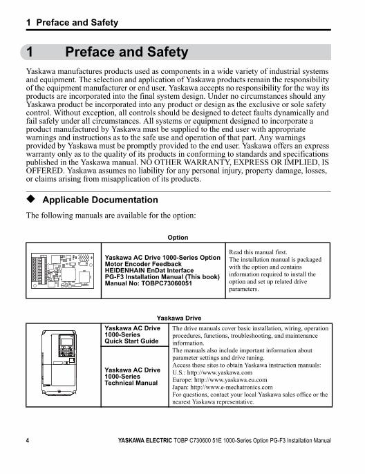
◆ Applicable DocumentationThe following manuals are available for the option:
Option
Yaskawa AC Drive 1000-Series Option Motor Encoder Feedback HEIDENHAIN EnDat Interface PG-F3 Installation Manual (This book)Manual No: TOBPC73060051
Read this manual first.The installation manual is packaged with the option and contains information required to install the option and set up related drive parameters.
Yaskawa DriveYaskawa AC Drive 1000-SeriesQuick Start Guide
The drive manuals cover basic installation, wiring, operation procedures, functions, troubleshooting, and maintenance information.The manuals also include important information about parameter settings and drive tuning.Access these sites to obtain Yaskawa instruction manuals:U.S.: http://www.yaskawa.comEurope: http://www.yaskawa.eu.comJapan: http://www.e-mechatronics.comFor questions, contact your local Yaskawa sales office or the nearest Yaskawa representative.
Yaskawa AC Drive 1000-Series Technical Manual
F3
4 YASKAWA ELECTRIC TOBP C730600 51E 1000-Series Option PG-F3 Installation Manual

1 Preface and Safety
◆ Terms and Abbreviations
◆ Registered TrademarksTrademarks are the property of their respective owners.
Note: Indicates supplemental information that is not related to safety messagesDrive: Yaskawa AC Drive 1000-SeriesOption: Yaskawa AC Drive 1000-Series Option Motor Encoder Feedback HEIDENHAIN EnDat Interface:
Type PG-F3PG: Pulse Generator or Encoder mounted on the motorV/f: V/f ControlV/f w/PG: V/f Control with PGCLV: Closed Loop Vector Control AOLV/PM: Advanced Open Loop Vector Control for PMCLV/PM: Closed Loop Vector Control for PM
YASKAWA ELECTRIC TOBP C730600 51E 1000-Series Option PG-F3 Installation Manual 5
1 Preface and Safety
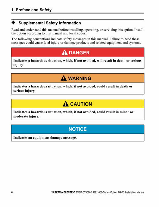
◆ Supplemental Safety InformationRead and understand this manual before installing, operating, or servicing this option. Install the option according to this manual and local codes.The following conventions indicate safety messages in this manual. Failure to heed these messages could cause fatal injury or damage products and related equipment and systems.
DANGERIndicates a hazardous situation, which, if not avoided, will result in death or serious injury.
W ARNING Indicates a hazardous situation, which, if not avoided, could result in death or serious injury.
CAUTION Indicates a hazardous situation, which, if not avoided, could result in minor or moderate injury.
NOTICEIndicates an equipment damage message.
6 YASKAWA ELECTRIC TOBP C730600 51E 1000-Series Option PG-F3 Installation Manual
1 Preface and Safety
■ General Safety
General Precautions• The diagrams in this book may include options and drives without covers or safety shields to
illustrate details. Be sure to reinstall covers or shields before operating any devices. Use the option according to the instructions described in this manual.
• Any illustrations, photographs, or examples used in this manual are provided as examples only and may not apply to all products to which this manual is applicable.
• The products and specifications described in this manual or the content and presentation of the manual may be changed without notice to improve the product and/or the manual.
• When ordering new copies of the manual, contact a Yaskawa representative or the nearest Yaskawa sales office and provide the manual number shown on the front cover.
DANGERHeed the safety messages in this manual.Failure to comply will result in death or serious injury.The operating company is responsible for any injuries or equipment damage resulting from failure to heed the warnings in this manual.
NOTICEDo not modify the drive or option circuitry.Failure to comply could result in damage to the drive or option and will void warranty. Yaskawa is not responsible for any modification of the product made by the user. This product must not be modified.Do not expose the drive or option to halogen group disinfectants.Failure to comply may cause damage to the electrical components in the option. Do not pack the drive in wooden materials that have been fumigated or sterilized.Do not sterilize the entire package after the product is packed.
YASKAWA ELECTRIC TOBP C730600 51E 1000-Series Option PG-F3 Installation Manual 7
8 YASKAWA ELECTRIC TOBP C730600 51E 1000-Series Option PG-F3 Installation Manual
2 Product Overview
2 Product Overview
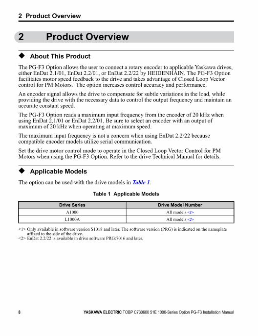
◆ About This ProductThe PG-F3 Option allows the user to connect a rotary encoder to applicable Yaskawa drives, either EnDat 2.1/01, EnDat 2.2/01, or EnDat 2.2/22 by HEIDENHAIN. The PG-F3 Option facilitates motor speed feedback to the drive and takes advantage of Closed Loop Vector control for PM Motors. The option increases control accuracy and performance.An encoder signal allows the drive to compensate for subtle variations in the load, while providing the drive with the necessary data to control the output frequency and maintain an accurate constant speed.The PG-F3 Option reads a maximum input frequency from the encoder of 20 kHz when using EnDat 2.1/01 or EnDat 2.2/01. Be sure to select an encoder with an output of maximum of 20 kHz when operating at maximum speed.The maximum input frequency is not a concern when using EnDat 2.2/22 because compatible encoder models utilize serial communication.Set the drive motor control mode to operate in the Closed Loop Vector Control for PM Motors when using the PG-F3 Option. Refer to the drive Technical Manual for details.
◆ Applicable ModelsThe option can be used with the drive models in Table 1.
Table 1 Applicable Models
Drive Series
<1> Only available in software version S1018 and later. The software version (PRG) is indicated on the nameplate affixed to the side of the drive.
<2> EnDat 2.2/22 is available in drive software PRG:7016 and later.
Drive Model NumberA1000 All models <1>
L1000A All models <2>
YASKAWA ELECTRIC TOBP C730600 51E 1000-Series Option PG-F3 Installation Manual 9
3 Receiving
3 ReceivingPlease perform the following tasks upon receiving the option:• Inspect the option for damage. Contact the shipper immediately if the option appears
damaged upon receipt.• Verify receipt of the correct model by checking the model number printed on the option
nameplate (Refer to Figure 1 on page 10 for more information).• Contact your supplier if you have received the wrong model or the option does not
function properly.
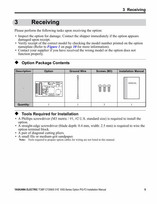
◆ Option Package Contents
◆ Tools Required for Installation• A Phillips screwdriver (M3 metric / #1, #2 U.S. standard size) is required to install the
option.• A straight-edge screwdriver (blade depth: 0.4 mm, width: 2.5 mm) is required to wire the
option terminal block.• A pair of diagonal cutting pliers.• A small file or medium-grit sandpaper.
Note: Tools required to prepare option cables for wiring are not listed in this manual.
Description: Option Ground Wire Screws (M3) Installation Manual
–
Quantity: 1 1 3 1
F3
F3
MANUAL
10 YASKAWA ELECTRIC TOBP C730600 51E 1000-Series Option PG-F3 Installation Manual
4 Option Components
4 Option Components
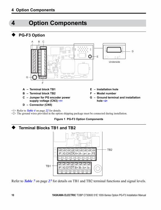
◆ PG-F3 OptionFigure 1
Figure 1 PG-F3 Option Components
◆ Terminal Blocks TB1 and TB2
Refer to Table 7 on page 27 for details on TB1 and TB2 terminal functions and signal levels.
A – Terminal block TB1 E – Installation holeB – Terminal block TB2 F – Model numberC – Jumper for PG encoder power
supply voltage (CN3) <1>G – Ground terminal and installation
hole <2>
<1> Refer to Table 4 on page 22 for details.<2> The ground wires provided in the option shipping package must be connected during installation.
D – Connector (CN5)
G
E
A
F
CB
D
Underside
PG-F3
CN3
F3
IP b–b+B+ B–DTDTIGTB1
TB2IP IG CK CK A+ A– a+ a– FE
F3

5 Installation Procedure
5 Installation Procedure
◆ Section Safety
DANGERElectric Shock Hazard
Do not connect or disconnect wiring while the power is on.Failure to comply will result in death or serious injury.Disconnect all power to the drive, wait at least the amount of time specified on the drive front cover safety label. After all indicators are off, measure the DC bus voltage to confirm safe level, and check for unsafe voltages before servicing. The internal capacitor remains charged after the power supply is turned off.
W ARNING Electrical Shock Hazard
Do not remove the front covers of the drive while the power is on.Failure to comply could result in death or serious injury.The diagrams in this section may include options and drives without covers or safety shields to show details. Be sure to reinstall covers or shields before operating any devices. Use the option according to the instructions described in this manual.
Do not allow unqualified personnel to use equipment.Failure to comply could result in death or serious injury.Maintenance, inspection, and replacement of parts must be performed only by authorized personnel familiar with installation, adjustment, and maintenance of this product.
Do not touch circuit boards while the power to the drive is on.Failure to comply could result in death or serious injury.
YASKAWA ELECTRIC TOBP C730600 51E 1000-Series Option PG-F3 Installation Manual 11
5 Installation Procedure
Do not use damaged wires, stress the wiring, or damage the wire insulation.Failure to comply could result in death or serious injury.
Fire HazardTighten all terminal screws to the specified tightening torque.Loose electrical connections could result in death or serious injury by fire due to overheating of electrical connections.
NOTICE
Damage to EquipmentObserve proper electrostatic discharge (ESD) procedures when handling the option, drive, and circuit boards.Failure to comply may result in ESD damage to circuitry.
Never shut the power off while the drive is running or outputting voltage.Failure to comply may cause the application to operate incorrectly or damage the drive.
Do not operate damaged equipment. Failure to comply may cause further damage to the equipment.Do not connect or operate any equipment with visible damage or missing parts.
Tighten all terminal screws to the specified tightening torque.Failure to comply could result in damage to the terminal block.
Do not use unshielded cable for control wiring.Failure to comply may cause electrical interference resulting in poor system performance.Use shielded twisted-pair wires and ground the shield to the ground terminal of the drive.
W ARNING
12 YASKAWA ELECTRIC TOBP C730600 51E 1000-Series Option PG-F3 Installation Manual
5 Installation Procedure
Properly connect all pins and connectors. Failure to comply may prevent proper operation and possibly damage equipment.
Check wiring to ensure that all connections are correct after installing the option and connecting any other devices. Failure to comply may result in damage to the option.
NOTICE
YASKAWA ELECTRIC TOBP C730600 51E 1000-Series Option PG-F3 Installation Manual 13
5 Installation Procedure
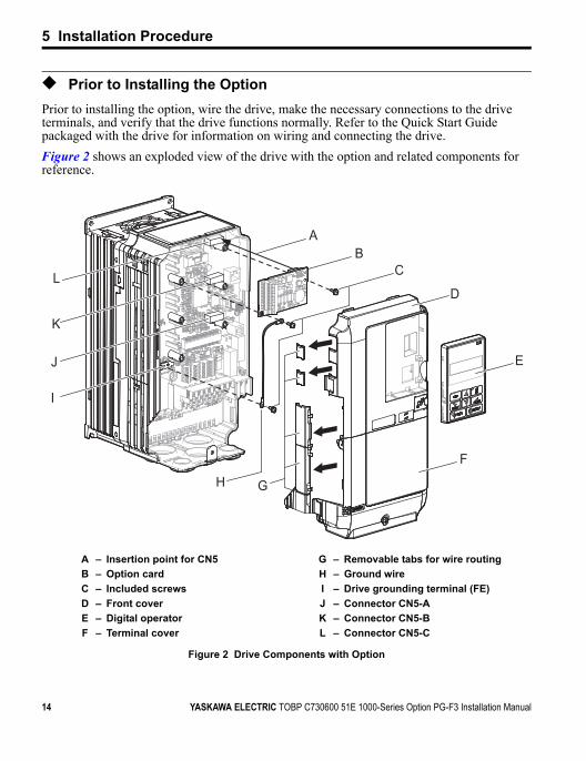
◆ Prior to Installing the OptionPrior to installing the option, wire the drive, make the necessary connections to the drive terminals, and verify that the drive functions normally. Refer to the Quick Start Guide packaged with the drive for information on wiring and connecting the drive.Figure 2 shows an exploded view of the drive with the option and related components for reference.Figure 2
Figure 2 Drive Components with Option
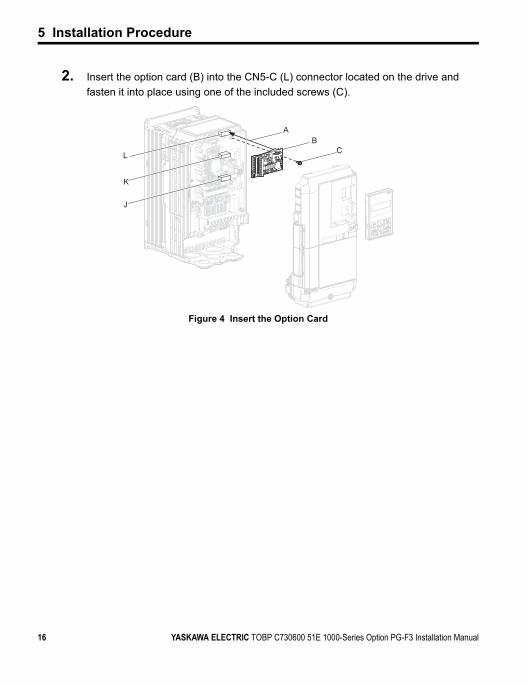
A – Insertion point for CN5 G – Removable tabs for wire routingB – Option card H – Ground wireC – Included screws I – Drive grounding terminal (FE)D – Front cover J – Connector CN5-AE – Digital operator K – Connector CN5-BF – Terminal cover L – Connector CN5-C
G
AB
C
H
D
E
F
I
J
K
L
14 YASKAWA ELECTRIC TOBP C730600 51E 1000-Series Option PG-F3 Installation Manual
5 Installation Procedure
◆ Installing the OptionRefer to the instructions below to install the option.
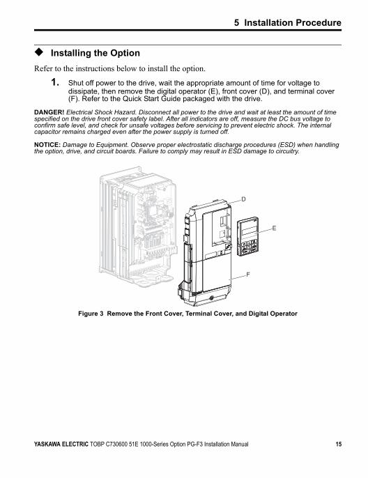
1. Shut off power to the drive, wait the appropriate amount of time for voltage to dissipate, then remove the digital operator (E), front cover (D), and terminal cover (F). Refer to the Quick Start Guide packaged with the drive.
DANGER! Electrical Shock Hazard. Disconnect all power to the drive and wait at least the amount of time specified on the drive front cover safety label. After all indicators are off, measure the DC bus voltage to confirm safe level, and check for unsafe voltages before servicing to prevent electric shock. The internal capacitor remains charged even after the power supply is turned off.
NOTICE: Damage to Equipment. Observe proper electrostatic discharge procedures (ESD) when handling the option, drive, and circuit boards. Failure to comply may result in ESD damage to circuitry.Figure 3
Figure 3 Remove the Front Cover, Terminal Cover, and Digital Operator
D
E
F
YASKAWA ELECTRIC TOBP C730600 51E 1000-Series Option PG-F3 Installation Manual 15
5 Installation Procedure
2. Insert the option card (B) into the CN5-C (L) connector located on the drive and fasten it into place using one of the included screws (C).
Figure 4
Figure 4 Insert the Option Card
K
J
L
AB
C
16 YASKAWA ELECTRIC TOBP C730600 51E 1000-Series Option PG-F3 Installation Manual
5 Installation Procedure
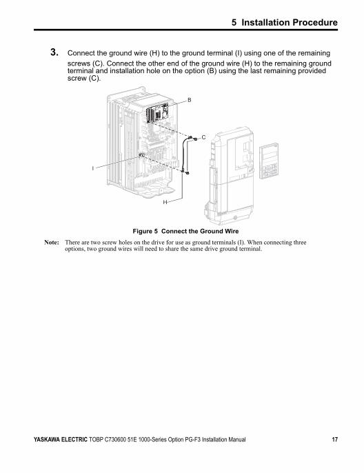
3. Connect the ground wire (H) to the ground terminal (I) using one of the remaining screws (C). Connect the other end of the ground wire (H) to the remaining ground terminal and installation hole on the option (B) using the last remaining provided screw (C).
Figure 5
Figure 5 Connect the Ground WireNote: There are two screw holes on the drive for use as ground terminals (I). When connecting three
options, two ground wires will need to share the same drive ground terminal.
I
B
H
C
YASKAWA ELECTRIC TOBP C730600 51E 1000-Series Option PG-F3 Installation Manual 17

5 Installation Procedure
4. Prepare and connect the wire ends as shown in Figure 6 and Figure 7. Refer to Wire Gauges and Tightening Torques on page 26 to confirm that the proper tightening torque is applied to each terminal. Take particular precaution to ensure that each wire is properly connected and wire insulation is not accidentally pinched into electrical terminals.
WARNING! Fire Hazard. Tighten all terminal screws according to the specified tightening torque. Loose electrical connections could result in death or serious injury by fire due to overheating electrical connections. Tightening screws beyond the specified tightening torque may result in erroneous operation, damage the terminal block, or cause a fire.
NOTICE: Heat shrink tubing or electrical tape may be required to ensure that cable shielding does not contact other wiring. Insufficient insulation may cause a short circuit and damage the option or drive.Figure 6
Figure 6 Preparing Ends of Shielded CableFigure 7
Figure 7 Preparing and Connecting Cable Wiring
5. Wire the motor PG encoder to the terminal block on the option.
• Wiring EnDat 2.1/01 or EnDat 2.2/01 EncodersWire the motor PG encoder to the terminal block on the option using a HEIDENHAIN 17-conductor cable. Refer to Figure 6 and Figure 7 for wiring instructions. Refer to
Insulation
Shield sheath
Shield
PG option terminal PG at motor
FE/SDGround Terminal
(Insulate with electrical tape or shrink tubing)
F3
Option terminal block
Preparing wire ends: Screwdriver blade size
about 5.5 mm (7/32”)When not usingcrimped insulatedsleeves
Pull back the shielding and lightly twist the end with fingers, keeping the ends from fraying.
To PG at motor(do not solder ends)
Loosen the screws and insert the wire into the opening on the terminal block.
Blade depth of 0.4 mm or less
Blade width of 2.5 mm or less
F3
18 YASKAWA ELECTRIC TOBP C730600 51E 1000-Series Option PG-F3 Installation Manual
5 Installation Procedure
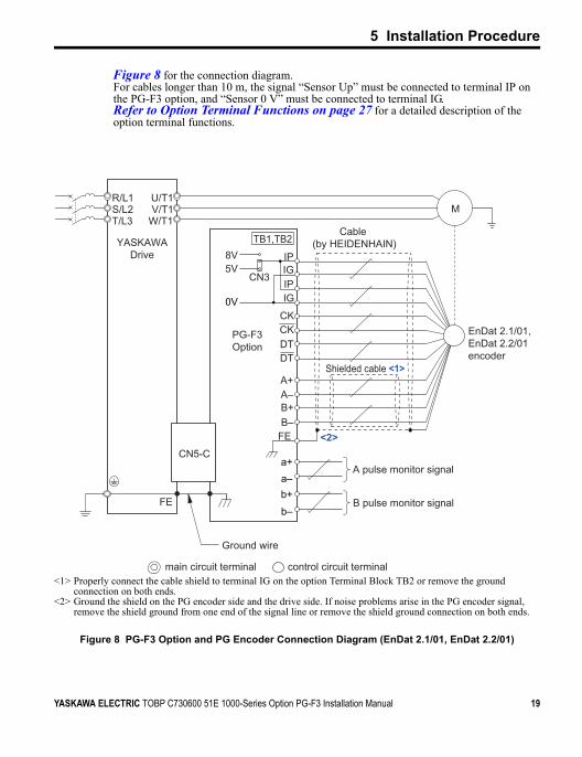
Figure 8 for the connection diagram.For cables longer than 10 m, the signal “Sensor Up” must be connected to terminal IP on the PG-F3 option, and “Sensor 0 V” must be connected to terminal IG. Refer to Option Terminal Functions on page 27 for a detailed description of the option terminal functions.
Figure 8 PG-F3 Option and PG Encoder Connection Diagram (EnDat 2.1/01, EnDat 2.2/01)
<1> Properly connect the cable shield to terminal IG on the option Terminal Block TB2 or remove the ground connection on both ends.
<2> Ground the shield on the PG encoder side and the drive side. If noise problems arise in the PG encoder signal, remove the shield ground from one end of the signal line or remove the shield ground connection on both ends.
0V
IP
IPIG
IG
CN3
8V5V
a–
M
CN5-C
YASKAWADrive
PG-F3Option
U/T1V/T1
W/T1
R/L1S/L2T/L3
FE
B+B–
A–A+
DTDTCKCK
TB1,TB2
FE
a+
b+
b–
Cable (by HEIDENHAIN)
EnDat 2.1/01, EnDat 2.2/01encoder
A pulse monitor signal
B pulse monitor signal
main circuit terminal control circuit terminal
<2>
Shielded cable <1>
Ground wire
F3
YASKAWA ELECTRIC TOBP C730600 51E 1000-Series Option PG-F3 Installation Manual 19

5 Installation Procedure
Table 2 PG Encoder Cable Specification (EnDat 2.1/01, EnDat 2.2/01)
Option TerminalPG Encoder Cable
Color PG Encoder Signal
IPBrown/Green Up
Blue Sensor Up
IGWhite/Green 0V
White Sensor 0VCK Purple CLOCK
CK Yellow CLOCK
DT Gray DATA
DT Pink DATA
A+ Green/Black A+
A– Yellow/Black A–
B+ Blue/Black B+
B– Red/Black B–
20 YASKAWA ELECTRIC TOBP C730600 51E 1000-Series Option PG-F3 Installation Manual
5 Installation Procedure
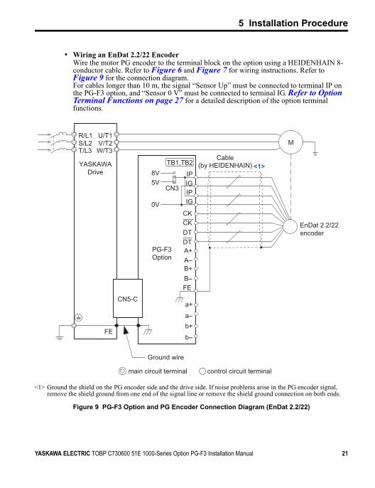
• Wiring an EnDat 2.2/22 EncoderWire the motor PG encoder to the terminal block on the option using a HEIDENHAIN 8-conductor cable. Refer to Figure 6 and Figure 7 for wiring instructions. Refer to Figure 9 for the connection diagram.For cables longer than 10 m, the signal “Sensor Up” must be connected to terminal IP on the PG-F3 option, and “Sensor 0 V” must be connected to terminal IG. Refer to Option Terminal Functions on page 27 for a detailed description of the option terminal functions.
Figure 9 PG-F3 Option and PG Encoder Connection Diagram (EnDat 2.2/22)
<1> Ground the shield on the PG encoder side and the drive side. If noise problems arise in the PG encoder signal, remove the shield ground from one end of the signal line or remove the shield ground connection on both ends.
b–
b+a–
a+
B–B+A–A+
FE
DTDTCKCK
IGIPIGIP
CN3
TB1,TB2
PG-F3Option
8V5V
0V
EnDat 2.2/22 encoder
M
Cable(by HEIDENHAIN)
U/T1V/T2W/T3
R/L1S/L2T/L3
YASKAWADrive
FE
CN5-C
main circuit terminal control circuit terminal
<1>
Ground wire
F3
YASKAWA ELECTRIC TOBP C730600 51E 1000-Series Option PG-F3 Installation Manual 21

5 Installation Procedure
Table 3 PG Encoder Cable Specification (EnDat 2.2/22)
6. Set the voltage for the PG encoder power supply using jumper CN3 located on the option. Position the jumper as shown in Table 4 to select the voltage level.
NOTICE: The positioning of jumper CN3 selects the PG encoder power supply voltage (5 V or 8 V). Select the voltage level for the PG encoder connected to the option and motor. If the wrong voltage is selected, the PG encoder may not operate properly or may become damaged as a result.
Table 4 Setting the PG Encoder Power Supply Voltage (IP) with Jumper CN3
Option TerminalPG Encoder Cable
Color PG Encoder Signal
IPBrown/Green Up
Blue Sensor Up
IGWhite/Green 0V
White Sensor 0VCK Purple CLOCK
CK Yellow CLOCK
DT Gray DATA
DT Pink DATA
A+ − −
A– − −
B+ − −
B– − −
Voltage Level 5 V ± 5% (default) 8 V ± 10%
Jumper CN3 Position 5 V
8 V
5 V
8 V
22 YASKAWA ELECTRIC TOBP C730600 51E 1000-Series Option PG-F3 Installation Manual

5 Installation Procedure
7. Route the option wiring. Depending on the drive model, some drives may require routing the wiring through the side of the front cover to the outside. In these cases, cut out the perforated openings on the left side of the drive front cover as shown in Figure 10-A and leave no sharp edges to damage wiring. Route the wiring inside the enclosure as shown in Figure 10-B for drives that do not require routing through the front cover.Refer to the Peripheral Devices & Options section of the drive Technical Manual for more information.
Figure 8
Figure 10 Wire Routing Examples
A – Route wires through the openings provided on the left side of the front cover. <1>
<1> The drive will not meet NEMA Type 1 requirements if wiring is exposed outside the enclosure.
B – Use the open space provided inside the drive to route option wiring.
B
A
YASKAWA ELECTRIC TOBP C730600 51E 1000-Series Option PG-F3 Installation Manual 23

5 Installation Procedure
8. Replace and secure the front covers of the drive (D, F) and replace the digital operator (E).
Figure 9
Figure 11 Replace the Front Covers and Digital OperatorNote: Take proper precautions when wiring the option so that the front covers will easily fit back onto
the drive. Make sure cables are not pinched between the front covers and the drive when replacing the covers.
D
E
F
24 YASKAWA ELECTRIC TOBP C730600 51E 1000-Series Option PG-F3 Installation Manual
5 Installation Procedure
9. Set drive parameters in Table 8 for proper motor rotation.
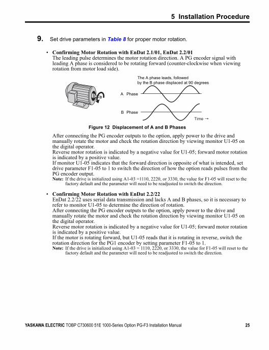
• Confirming Motor Rotation with EnDat 2.1/01, EnDat 2.2/01The leading pulse determines the motor rotation direction. A PG encoder signal with leading A phase is considered to be rotating forward (counter-clockwise when viewing rotation from motor load side).
Figure 10
Figure 12 Displacement of A and B Phases
After connecting the PG encoder outputs to the option, apply power to the drive and manually rotate the motor and check the rotation direction by viewing monitor U1-05 on the digital operator.Reverse motor rotation is indicated by a negative value for U1-05; forward motor rotation is indicated by a positive value.If monitor U1-05 indicates that the forward direction is opposite of what is intended, set drive parameter F1-05 to 1 to switch the direction of how the option reads pulses from the PG encoder output.Note: If the drive is initialized using A1-03 =1110, 2220, or 3330, the value for F1-05 will reset to the
factory default and the parameter will need to be readjusted to switch the direction.
• Confirming Motor Rotation with EnDat 2.2/22EnDat 2.2/22 uses serial data transmission and lacks A and B phases, so it is necessary to refer to monitor U1-05 to determine the direction of rotation.After connecting the PG encoder outputs to the option, apply power to the drive and manually rotate the motor and check the rotation direction by viewing monitor U1-05 on the digital operator.Reverse motor rotation is indicated by a negative value for U1-05; forward motor rotation is indicated by a positive value.If the motor is rotating forward, but U1-05 reads that it is rotating in reverse, switch the rotation direction for the PG1 encoder by setting parameter F1-05 to 1.Note: If the drive is initialized using A1-03 = 1110, 2220, or 3330, the value for F1-05 will reset to the
factory default and the parameter will need to be readjusted to switch the direction.
A
B
The A phase leads, followedby the B phase displaced at 90 degrees
Time →
Phase
PhaseF3
YASKAWA ELECTRIC TOBP C730600 51E 1000-Series Option PG-F3 Installation Manual 25
5 Installation Procedure
◆ Wire Gauges, Tightening Torque, and Crimp Terminals
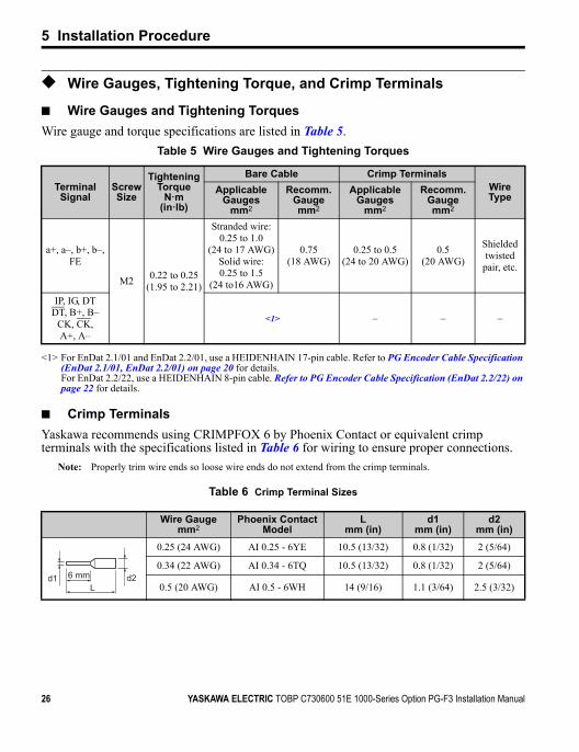
■ Wire Gauges and Tightening TorquesWire gauge and torque specifications are listed in Table 5.
Table 5 Wire Gauges and Tightening Torques
■ Crimp TerminalsYaskawa recommends using CRIMPFOX 6 by Phoenix Contact or equivalent crimp terminals with the specifications listed in Table 6 for wiring to ensure proper connections.
Note: Properly trim wire ends so loose wire ends do not extend from the crimp terminals.
Table 6 Crimp Terminal Sizes
Terminal Signal
Screw Size
Tightening Torque
N m(in lb)
Bare Cable Crimp TerminalsWire Type
Applicable Gauges
mm2
Recomm. Gaugemm2
Applicable Gauges
mm2
Recomm. Gaugemm2
a+, a–, b+, b–, FE
M2 0.22 to 0.25(1.95 to 2.21)
Stranded wire: 0.25 to 1.0
(24 to 17 AWG)Solid wire:0.25 to 1.5
(24 to16 AWG)
0.75(18 AWG)
0.25 to 0.5(24 to 20 AWG)
0.5(20 AWG)
Shielded twisted
pair, etc.
IP, IG, DTDT, B+, B–
CK, CK, A+, A–
<1>
<1> For EnDat 2.1/01 and EnDat 2.2/01, use a HEIDENHAIN 17-pin cable. Refer to PG Encoder Cable Specification (EnDat 2.1/01, EnDat 2.2/01) on page 20 for details.For EnDat 2.2/22, use a HEIDENHAIN 8-pin cable. Refer to PG Encoder Cable Specification (EnDat 2.2/22) on page 22 for details.
– – –
Wire Gaugemm2
Phoenix Contact Model
Lmm (in)
d1mm (in)
d2mm (in)
0.25 (24 AWG) AI 0.25 - 6YE 10.5 (13/32) 0.8 (1/32) 2 (5/64)
0.34 (22 AWG) AI 0.34 - 6TQ 10.5 (13/32) 0.8 (1/32) 2 (5/64)
0.5 (20 AWG) AI 0.5 - 6WH 14 (9/16) 1.1 (3/64) 2.5 (3/32)d1 d26 mm
L
26 YASKAWA ELECTRIC TOBP C730600 51E 1000-Series Option PG-F3 Installation Manual
5 Installation Procedure
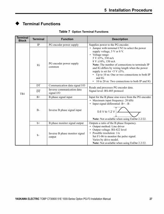
◆ Terminal Functions
Table 7 Option Terminal Functions
Terminal Block Terminal Function Description
TB1
IP PG encoder power supply Supplies power to the PG encoder.• Jumper with terminal CN3 to select the power
supply voltage, 5 V or 8 V.• Voltage range:
5 V ±5%, 330 mA8 V ±10%, 150 mANote: The number of connections to terminals IP and IG differs by wiring length when the power supply is set for +5 V ±5%.• Up to 10 m: One or two connections to both IP
and IG.• 10 to 20 m: Two connections to both IP and IG.
IG PG encoder power supply common
DT Communication data signal I/OReads and processes PG encoder data.Signal level: RS-485 protocolDT Inverse communication data
signal I/OB+ B phase signal input Input for the B phase sine-wave from the PG encoder.
• Maximum input frequency: 20 kHz• Input signal differential: B+ - B–
Note: Not available when using EnDat 2.2/22.
B– Inverse B phase signal input
b+ B phase monitor signal output Outputs a ratio of the B phase frequency.• Output method: Line driver• Output voltage: RS-422 level• Possible resolution: 1/n
Set F1-06 to monitor the pulse signal.Varies by drive model.Note: Not available when using EnDat 2.2/22.
b– Inverse B phase monitor signal output
0.6 V to 1.2 V
YASKAWA ELECTRIC TOBP C730600 51E 1000-Series Option PG-F3 Installation Manual 27
5 Installation Procedure
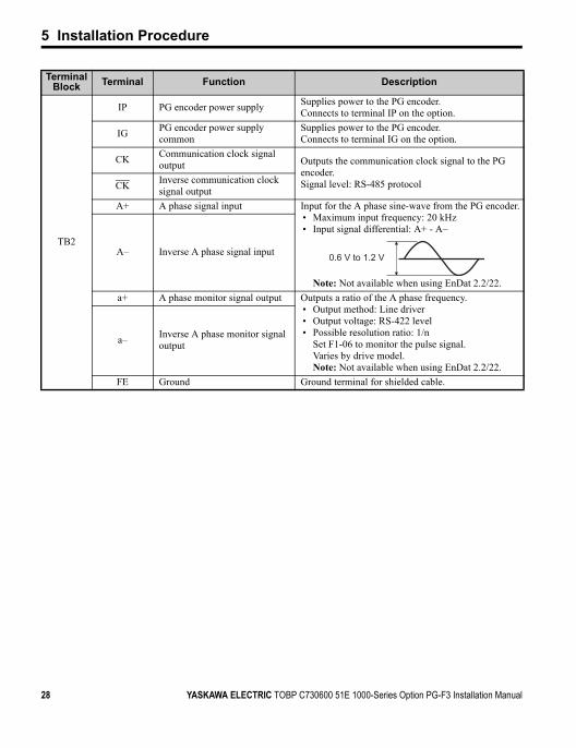
TB2
IP PG encoder power supply Supplies power to the PG encoder.Connects to terminal IP on the option.
IG PG encoder power supply common
Supplies power to the PG encoder.Connects to terminal IG on the option.
CK Communication clock signal output Outputs the communication clock signal to the PG
encoder.Signal level: RS-485 protocolCK Inverse communication clock
signal outputA+ A phase signal input Input for the A phase sine-wave from the PG encoder.
• Maximum input frequency: 20 kHz• Input signal differential: A+ - A–
Note: Not available when using EnDat 2.2/22.
A– Inverse A phase signal input
a+ A phase monitor signal output Outputs a ratio of the A phase frequency.• Output method: Line driver• Output voltage: RS-422 level• Possible resolution ratio: 1/n
Set F1-06 to monitor the pulse signal.Varies by drive model.Note: Not available when using EnDat 2.2/22.
a– Inverse A phase monitor signal output
FE Ground Ground terminal for shielded cable.
Terminal Block Terminal Function Description
0.6 V to 1.2 V
28 YASKAWA ELECTRIC TOBP C730600 51E 1000-Series Option PG-F3 Installation Manual
6 Related Parameters
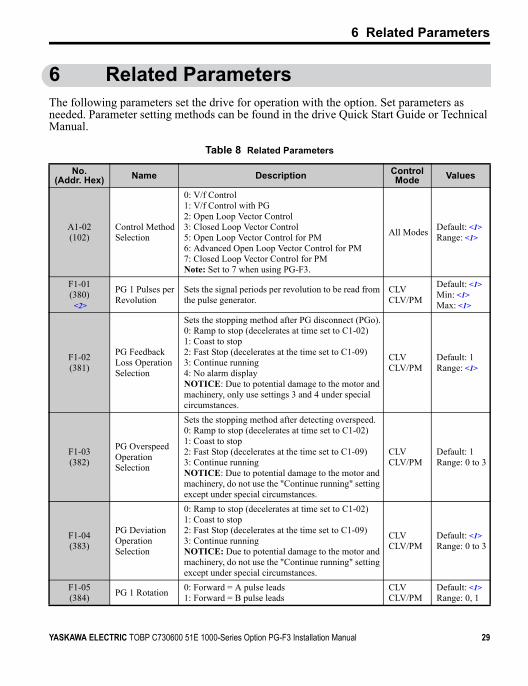
6 Related ParametersThe following parameters set the drive for operation with the option. Set parameters as needed. Parameter setting methods can be found in the drive Quick Start Guide or Technical Manual.
Table 8 Related Parameters
No.(Addr. Hex) Name Description Control
Mode Values
A1-02(102)
Control Method Selection
0: V/f Control1: V/f Control with PG2: Open Loop Vector Control3: Closed Loop Vector Control 5: Open Loop Vector Control for PM6: Advanced Open Loop Vector Control for PM7: Closed Loop Vector Control for PMNote: Set to 7 when using PG-F3.
All Modes Default: <1>Range: <1>
F1-01(380)
<2>
PG 1 Pulses per Revolution
Sets the signal periods per revolution to be read from the pulse generator.
CLVCLV/PM
Default: <1>Min: <1>Max: <1>
F1-02(381)
PG Feedback Loss Operation Selection
Sets the stopping method after PG disconnect (PGo).0: Ramp to stop (decelerates at time set to C1-02)1: Coast to stop2: Fast Stop (decelerates at the time set to C1-09)3: Continue running4: No alarm displayNOTICE: Due to potential damage to the motor and machinery, only use settings 3 and 4 under special circumstances.
CLVCLV/PM
Default: 1Range: <1>
F1-03(382)
PG Overspeed Operation Selection
Sets the stopping method after detecting overspeed.0: Ramp to stop (decelerates at time set to C1-02)1: Coast to stop2: Fast Stop (decelerates at the time set to C1-09)3: Continue runningNOTICE: Due to potential damage to the motor and machinery, do not use the "Continue running" setting except under special circumstances.
CLVCLV/PM
Default: 1Range: 0 to 3
F1-04(383)
PG Deviation Operation Selection
0: Ramp to stop (decelerates at time set to C1-02)1: Coast to stop2: Fast Stop (decelerates at the time set to C1-09)3: Continue runningNOTICE: Due to potential damage to the motor and machinery, do not use the "Continue running" setting except under special circumstances.
CLVCLV/PM
Default: <1>Range: 0 to 3
F1-05(384) PG 1 Rotation 0: Forward = A pulse leads
1: Forward = B pulse leadsCLVCLV/PM
Default: <1>Range: 0, 1
YASKAWA ELECTRIC TOBP C730600 51E 1000-Series Option PG-F3 Installation Manual 29
6 Related Parameters
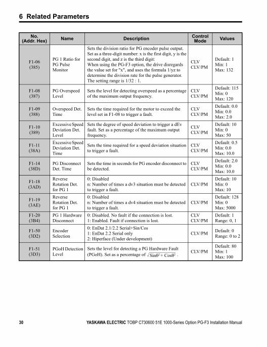
F1-06(385)
PG 1 Ratio for PG Pulse Monitor
Sets the division ratio for PG encoder pulse output. Set as a three-digit number: x is the first digit, y is the second digit, and z is the third digit:When using the PG-F3 option, the drive disregards the value set for "x", and uses the formula 1/yz to determine the division rate for the pulse generator. The setting range is 1/32 : 1.
CLVCLV/PM
Default: 1Min: 1Max: 132
F1-08(387)
PG Overspeed Level
Sets the level for detecting overspeed as a percentage of the maximum output frequency.
CLVCLV/PM
Default: 115Min: 0Max: 120
F1-09(388)
Overspeed Det. Time
Sets the time required for the motor to exceed the level set in F1-08 to trigger a fault.
CLVCLV/PM
Default: 0.0Min: 0.0Max: 2.0
F1-10(389)
Excessive Speed Deviation Det. Level
Sets the degree of speed deviation to trigger a dEv fault. Set as a percentage of the maximum output frequency.
CLVCLV/PM
Default: 10Min: 0Max: 50
F1-11(38A)
Excessive Speed Deviation Det. Time
Sets the time required for a speed deviation situation to trigger a fault.
CLVCLV/PM
Default: 0.5Min: 0.0Max: 10.0
F1-14(38D)
PG Disconnect Det. Time
Sets the time in seconds for PG encoder disconnect to be detected.
CLVCLV/PM
Default: 2.0Min: 0.0Max: 10.0
F1-18(3AD)
Reverse Rotation Det. for PG 1
0: Disabledn: Number of times a dv3 situation must be detected to trigger a fault.
CLV/PMDefault: 10Min: 0Max: 10
F1-19(3AE)
Reverse Rotation Det. for PG 1
0: Disabledn: Number of times a dv4 situation must be detected to trigger a fault.
CLV/PMDefault: 128Min: 0Max: 5000
F1-20(3B4)
PG 1 Hardware Disconnect
0: Disabled. No fault if the connection is lost.1: Enabled. Fault if connection is lost.
CLVCLV/PM
Default: 1Range: 0, 1
F1-50(3D2)
Encoder Selection
0: EnDat 2.1/2.2 Serial+Sin/Cos1: EnDat 2.2 Serial only2: Hiperface (Under development)
CLV/PM Default: 0Range: 0 to 2
F1-51(3D3)
PGoH Detection Level
Sets the level for detecting a PG Hardware Fault (PGoH). Set as a percentage of . CLV/PM
Default: 80Min: 1Max: 100
No.(Addr. Hex) Name Description Control
Mode Values
Sinθ2 + Cosθ2
30 YASKAWA ELECTRIC TOBP C730600 51E 1000-Series Option PG-F3 Installation Manual
6 Related Parameters
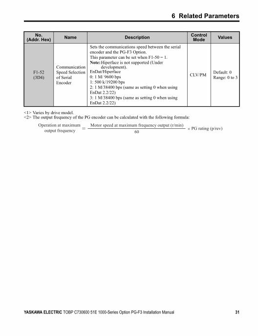
F1-52(3D4)
Communication Speed Selection of Serial Encoder
Sets the communications speed between the serial encoder and the PG-F3 Option. This parameter can be set when F1-50 = 1. Note:Hiperface is not supported (Under
development).EnDat/Hiperface0: 1 M/ 9600 bps1: 500 k/19200 bps2: 1 M/38400 bps (same as setting 0 when using EnDat 2.2/22)3: 1 M/38400 bps (same as setting 0 when using EnDat 2.2/22)
CLV/PM Default: 0Range: 0 to 3
<1> Varies by drive model.<2> The output frequency of the PG encoder can be calculated with the following formula:
No.(Addr. Hex) Name Description Control
Mode Values
Operation at maximum output frequency
Motor speed at maximum frequency output (r/min)60
× PG rating (p/rev)= F3
YASKAWA ELECTRIC TOBP C730600 51E 1000-Series Option PG-F3 Installation Manual 31
7 Troubleshooting
7 Troubleshooting
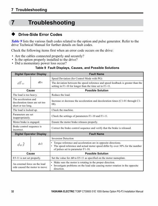
◆ Drive-Side Error CodesTable 9 lists the various fault codes related to the option and pulse generator. Refer to the drive Technical Manual for further details on fault codes.Check the following items first when an error code occurs on the drive: • Are the cables connected properly and securely?• Is the option properly installed to the drive?• Did a momentary power loss occur?
Table 9 Fault Displays, Causes, and Possible Solutions
Digital Operator Display Fault Name
dEvSpeed Deviation (for Control Mode with PG)The deviation between the speed reference and speed feedback is greater than the setting in F1-10 for longer than the time set to F1-11.
Cause Possible SolutionThe load is too heavy. Reduce the load. The acceleration anddeceleration times are set tooshort or too long.
Increase or decrease the acceleration and deceleration times (C1-01 through C1-08).
The load is locked up. Check the machine.Parameters are set inappropriately. Check the settings of parameters F1-10 and F1-11.
Motor brake is engaged. Ensure the motor brake releases properly.Brake control sequence is incorrect. Correct the brake control sequence and verify that the brake is released.
Digital Operator Display Fault Name
dv3
Inversion Detection• Torque reference and acceleration are in opposite directions.• The speed reference and actual motor speed differ by over 30% for the number
of pulses set to parameter F1-18.Cause Possible Solution
E5-11 is not set properly. Set the value for Δθ to E5-11 as specified on the motor nameplate.
An external force on the load side caused the motor to move.
• Make sure the motor is rotating in the proper direction.• Investigate problems on the load side causing motor rotation in the opposite
direction.
32 YASKAWA ELECTRIC TOBP C730600 51E 1000-Series Option PG-F3 Installation Manual

7 Troubleshooting
Noise interference along the PG encoder cable is affecting the A channel or B channel. • Check PG encoder wiring and make sure all wiring including shielded wiring is
properly connected.• If the problem continues after cycling power, replace the PG option or the PG
encoder.The PG encoder is disconnected or is not wired properly, or the PG option or PG encoder are damaged.The PG encoder rotational direction set to F1-05 is in the opposite direction of the motor wiring.
Make sure motor wiring for each phase (U, V, W) is connected properly.
Digital Operator Display Fault Name
dv4
Inversion Prevention DetectionPulses indicate that the motor is rotating in the opposite direction of the speed reference. Set the number of pulses to trigger inverse detection to F1-19.Note: To avoid nuisance faults, be sure to disable inverse detection in applications where the motor may rotate in the opposite direction of the speed reference. Set F1-19 to 0 to disable this feature.
Cause Possible Solution
E5-11 is not set properly.• Set the value for Δθ to E5-11 as specified on the motor nameplate.• If the problem continues after cycling power, replace the PG option or the PG
encoder.Noise interference along the PG encoder cable is affecting the A or B phase.
• Make sure the motor is rotating in the proper direction.• Investigate problems on the load-side that may be causing the motor to rotate in
the opposite direction.PG encoder is disconnected or is not wired properly, or the PG option or PG encoder are damaged.
• Check PG encoder wiring and make sure all wiring including shielded wiring is properly connected.
• If the problem continues after cycling power, replace the PG option or the PG encoder.
Digital Operator Display Fault Name
oFA00 Non-compatible option is connected to drive port CN5-A.
Cause Possible SolutionNon-compatible option is connected to drive port CN5-A.
Use only compatible options. Connect PG-F3 to CN5-C. For other options, refer to the Installation Manual for that option.
Digital Operator Display Fault Name
oFb00 Non-compatible option is connected to drive port CN5-B.
Cause Possible SolutionNon-compatible option is connected to drive port CN5-B.
Use only compatible options.Connect PG-F3 to CN5-C. For other options, refer to the Installation Manual for that option.
YASKAWA ELECTRIC TOBP C730600 51E 1000-Series Option PG-F3 Installation Manual 33
7 Troubleshooting
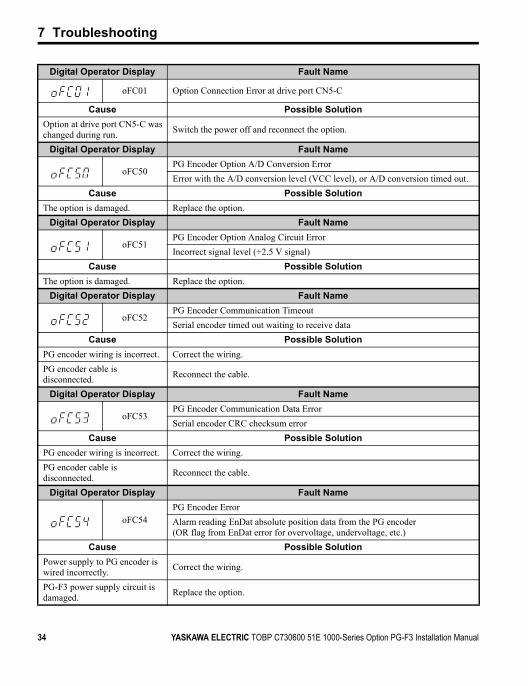
Digital Operator Display Fault Name
oFC01 Option Connection Error at drive port CN5-C
Cause Possible SolutionOption at drive port CN5-C was changed during run. Switch the power off and reconnect the option.
Digital Operator Display Fault Name
oFC50PG Encoder Option A/D Conversion ErrorError with the A/D conversion level (VCC level), or A/D conversion timed out.
Cause Possible SolutionThe option is damaged. Replace the option.
Digital Operator Display Fault Name
oFC51PG Encoder Option Analog Circuit ErrorIncorrect signal level (+2.5 V signal)
Cause Possible SolutionThe option is damaged. Replace the option.
Digital Operator Display Fault Name
oFC52PG Encoder Communication TimeoutSerial encoder timed out waiting to receive data
Cause Possible SolutionPG encoder wiring is incorrect. Correct the wiring.PG encoder cable is disconnected. Reconnect the cable.
Digital Operator Display Fault Name
oFC53PG Encoder Communication Data ErrorSerial encoder CRC checksum error
Cause Possible SolutionPG encoder wiring is incorrect. Correct the wiring.PG encoder cable is disconnected. Reconnect the cable.
Digital Operator Display Fault Name
oFC54PG Encoder ErrorAlarm reading EnDat absolute position data from the PG encoder(OR flag from EnDat error for overvoltage, undervoltage, etc.)
Cause Possible SolutionPower supply to PG encoder is wired incorrectly. Correct the wiring.
PG-F3 power supply circuit is damaged. Replace the option.
34 YASKAWA ELECTRIC TOBP C730600 51E 1000-Series Option PG-F3 Installation Manual
7 Troubleshooting
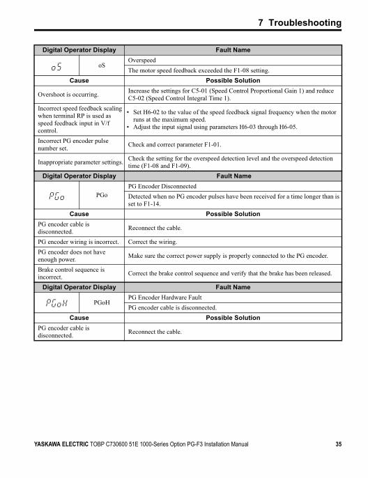
Digital Operator Display Fault Name
oSOverspeedThe motor speed feedback exceeded the F1-08 setting.
Cause Possible Solution
Overshoot is occurring. Increase the settings for C5-01 (Speed Control Proportional Gain 1) and reduce C5-02 (Speed Control Integral Time 1).
Incorrect speed feedback scaling when terminal RP is used as speed feedback input in V/f control.
• Set H6-02 to the value of the speed feedback signal frequency when the motor runs at the maximum speed.
• Adjust the input signal using parameters H6-03 through H6-05.
Incorrect PG encoder pulse number set. Check and correct parameter F1-01.
Inappropriate parameter settings. Check the setting for the overspeed detection level and the overspeed detection time (F1-08 and F1-09).
Digital Operator Display Fault Name
PGoPG Encoder DisconnectedDetected when no PG encoder pulses have been received for a time longer than is set to F1-14.
Cause Possible SolutionPG encoder cable is disconnected. Reconnect the cable.
PG encoder wiring is incorrect. Correct the wiring.PG encoder does not have enough power. Make sure the correct power supply is properly connected to the PG encoder.
Brake control sequence is incorrect. Correct the brake control sequence and verify that the brake has been released.
Digital Operator Display Fault Name
PGoHPG Encoder Hardware Fault PG encoder cable is disconnected.
Cause Possible SolutionPG encoder cable is disconnected. Reconnect the cable.
YASKAWA ELECTRIC TOBP C730600 51E 1000-Series Option PG-F3 Installation Manual 35
7 Troubleshooting
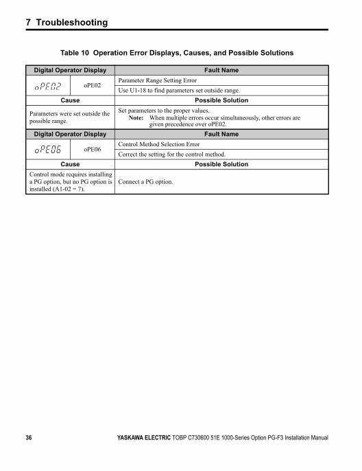
Table 10 Operation Error Displays, Causes, and Possible Solutions
Digital Operator Display Fault Name
oPE02Parameter Range Setting ErrorUse U1-18 to find parameters set outside range.
Cause Possible Solution
Parameters were set outside the possible range.
Set parameters to the proper values.Note: When multiple errors occur simultaneously, other errors are
given precedence over oPE02.Digital Operator Display Fault Name
oPE06Control Method Selection ErrorCorrect the setting for the control method.
Cause Possible SolutionControl mode requires installing a PG option, but no PG option is installed (A1-02 = 7).
Connect a PG option.
36 YASKAWA ELECTRIC TOBP C730600 51E 1000-Series Option PG-F3 Installation Manual

7 Troubleshooting
◆ Preventing Noise InterferenceTake the following steps to prevent erroneous operation caused by noise interference:• Use shielded wire for the PG encoder signal lines.• Limit the length of all motor output power cables to less than 20 m. • For PG encoder cables longer than 10 m, the signal “Sensor Up” must be connected to
terminal IP on the PG-F3 option, and “Sensor 0 V” must be connected to terminal IG.• Use separate conduit or cable tray dividers to separate option control wiring, main circuit
input power wiring, and motor output power cables.• Ground the shield on the PG encoder side and the drive side. If noise problems arise in the
PG encoder signal, verify that the shield is properly grounded and ground one end of the signal line or remove the ground connection on both ends.
• Properly connect the shield in cable to the IG on the option terminal or remove the ground connection on both ends.
■ Interface CircuitFigure 11
Figure 13 Interface Circuit (EnDat 2.1/01, EnDat 2.2/01)
120 Ω
120 Ω
PG-F3
CK
CK
DT
DT
a+
a–
b+
b–
2.5 V
PG Encoder
26LS31 Level
Clock
Data output
Data input
Monitor Signals
A–, B–
A+, B+
YASKAWA ELECTRIC TOBP C730600 51E 1000-Series Option PG-F3 Installation Manual 37
7 Troubleshooting
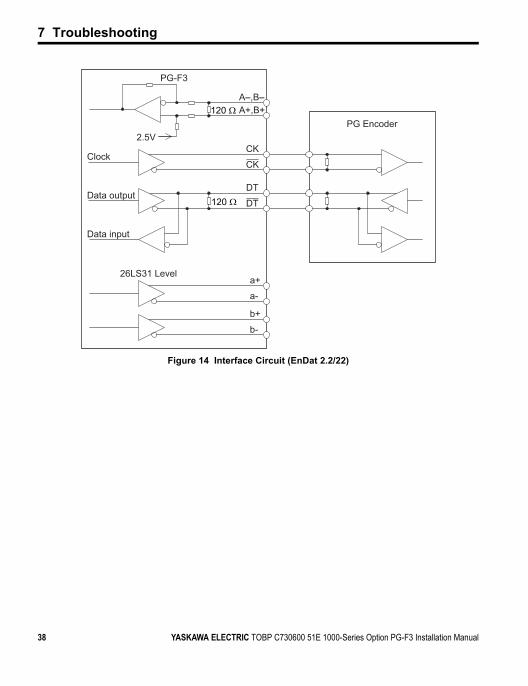
Figure 12
Figure 14 Interface Circuit (EnDat 2.2/22)
PG-F3
120 ΩA–,B–A+,B+
CK
CK
DT
DT120 Ω
a+
a-
b+
b-
2.5VPG Encoder
26LS31 Level
Clock
Data output
Data input
F3
38 YASKAWA ELECTRIC TOBP C730600 51E 1000-Series Option PG-F3 Installation Manual

YASKAWA ELECTRIC TOBP C730600 51E 1000-Series Option PG-F3 Installation Manual 39
8 Specifications
8 SpecificationsTable 11 Option Specifications
Items SpecificationsModel PG-F3
Compatible PG Encoder Types
EnDat 2.1/01, EnDat 2.2/01, EnDat 2.2/22 (HEIDENHAIN)ECN1313 (EnDat 2.1/01, EnDat 2.2/01)ECN113 (EnDat 2.1/01, EnDat 2.2/01)ECN413 (EnDat 2.1/01, EnDat 2.2/01)ECN1325 (EnDat 2.2/22)ECN125 (EnDat 2.2/22)ECN425 (EnDat 2.2/22)
Multi-turn Not available
PG Encoder Wiring Length
20 m(65 ft.) maximum. Wiring length over 10 m (32 ft.) requires two connections to both IP and IG.
PG Encoder Power Supply
Output voltage: 5 V ± 5%, 8 V ± 10%Maximum Output Current: 330 mA (5 V), 150 mA (8 V)
Compatible Control Modes Closed Loop Vector for PM motors
Maximum Input Frequency 20 kHz (only EnDat 2.1/01 and EnDat 2.2/01)
Pulse Monitor Output
Monitor for A and B phase outputMatches RS-422 Level
Note: Not available when using EnDat 2.2/22.PG Encoder Disconnect Detection
Software detection
Ambient Temperature -10°C to 50°C (14°F to 122°F)
Humidity 95% RH or lower with no condensationStorage Temperature -20°C to 60°C (-4°F to 140°F) allowed for short-term transport of the product
Area of Use Indoor (free of corrosive gas, airborne particles, etc.)Altitude 1000 m (3280 ft.) or lower

40 YASKAWA ELECTRIC TOBP C730600 51E 1000-Series Option PG-F3 Installation Manual
◆ Revision HistoryRevision dates and manual numbers appear on the bottom of the back cover.
Date of Publication Rev. No Section Revised Content
October 2012Chapter 2 Revision: Revised in accordance with software and hardware
upgrade.Back cover Revision: Address
July 2012 Back cover Revision: Address
July 2011 Entire Document Addition: EnDat 2.2/22 added along with corresponding data.
January 2011Front cover Revision: FormatBack cover Revision: Address, format
March 2010 Entire Document Edited for procedural clarity and readability.
November 2009 Entire Document Edited for procedural clarity and readability.
July 2009 − − First edition
MANUAL NO. TOBP C730600 51BPublished in Japan November 2009 09-7
Date of publicationDate of original publication
Revision number1
F3
6
5
4
3
2
1

DRIVE CENTER (INVERTER PLANT)2-13-1, Nishimiyaichi, Yukuhashi, Fukuoka, 824-8511, JapanPhone: 81-930-25-3844 Fax: 81-930-25-4369http://www.yaskawa.co.jp
YASKAWA ELECTRIC CORPORATIONNew Pier Takeshiba South Tower, 1-16-1, Kaigan, Minatoku, Tokyo, 105-6891, JapanPhone: 81-3-5402-4502 Fax: 81-3-5402-4580http://www.yaskawa.co.jp
YASKAWA AMERICA, INC.2121 Norman Drive South, Waukegan, IL 60085, U.S.A.Phone: (800) YASKAWA (927-5292) or 1-847-887-7000 Fax: 1-847-887-7310http://www.yaskawa.com
YASKAWA ELÉTRICO DO BRASIL LTDA.Avenda Fagundes Filho, 620 Bairro Saude, São Paulo, SP04304-000, BrazilPhone: 55-11-3585-1100 Fax: 55-11-5581-8795http://www.yaskawa.com.br
YASKAWA EUROPE GmbHHauptstrasse 185, 65760 Eschborn, GermanyPhone: 49-6196-569-300 Fax: 49-6196-569-398http://www.yaskawa.eu.com
YASKAWA ELECTRIC UK LTD.1 Hunt Hill Orchardton Woods, Cumbernauld, G68 9LF, United KingdomPhone: 44-1236-735000 Fax: 44-1236-458182http://www.yaskawa.co.uk
YASKAWA ELECTRIC KOREA CORPORATION9F, Kyobo Securities Bldg., 26-4, Yeouido-dong, Yeongdeungpo-gu, Seoul, 150-737, KoreaPhone: 82-2-784-7844 Fax: 82-2-784-8495http://www.yaskawa.co.kr
YASKAWA ELECTRIC (SINGAPORE) PTE. LTD.151 Lorong Chuan, #04-01, New Tech Park, 556741, SingaporePhone: 65-6282-3003 Fax: 65-6289-3003http://www.yaskawa.com.sg
YASKAWA ELECTRIC (CHINA) CO., LTD.12F, Carlton Bld., No.21 HuangHe Road, HuangPu District, Shanghai 200003, ChinaPhone: 86-21-5385-2200 Fax: 86-21-5385-3299http://www.yaskawa.com.cn
YASKAWA ELECTRIC (CHINA) CO., LTD. BEIJING OFFICERoom 1011, Tower W3 Oriental Plaza, No. 1 East Chang An Ave., Dong Cheng District, Beijing, 100738, ChinaPhone: 86-10-8518-4086 Fax: 86-10-8518-4082
YASKAWA ELECTRIC TAIWAN CORPORATION9F, 16, Nanking E. Rd., Sec. 3, Taipei, 104, TaiwanPhone: 886-2-2502-5003 Fax: 886-2-2505-1280
YASKAWA ELECTRIC INDIA PRIVATE LIMITED#17/A Electronics City, Hosur Road Bangalore 560 100 (Karnataka), IndiaPhone: 91-80-4244-1900 Fax: 91-80-4244-1901http://www.yaskawaindia.in
Published in Japan October 2012 09-7
MANUAL NO. TOBP C730600 51E
12-7-9
In the event that the end user of this product is to be the military and said product is to be employed in any weapons systems or the manufacture thereof, the export will fall under the relevant regulations as stipulated in the Foreign Exchange and Foreign Trade Regulations. Therefore, be sure to follow all procedures and submit all relevant documentation according to any and all rules, regulations and laws that may apply.
Specifications are subject to change without notice for ongoing product modifications and improvements.
© 2009-2012 YASKAWA ELECTRIC CORPORATION. All rights reserved.
6 -0
YASKAWA ELECTRIC CORPORATION
Motor Encoder FeedbackHEIDENHAIN EnDat Interface
YASKAWA AC Drive 1000-Series Option
Installation Manual