xtralis vesda vlc-800mx installation, … · vlc-800mx 17a-03-vlc 4 12/08 page 2 of 18 fig. 1...
TRANSCRIPT
VLC-800MX17A-03-VLC4 12/08
EQUIPMENT:
PUBLICATION:
ISSUE No. & DATE:
Xtralis VESDA VLC-800MX
INSTALLATION, COMMISSIONING AND SERVICING INSTRUCTIONS
LIST OF CONTENTS
1 TECHNICAL SPECIFICATION 2
2 INTRODUCTION 3
2.1 SCOPE OF THIS DOCUMENT 4
3 OPERATION 4
3.1 LED OPERATION 4
4 SAMPLING PIPEWORK 5
4.1 PRIMARY SAMPLING (OF AIRHANDLING UNIT RETURN GRILLES): 5
4.2 SECONDARY SAMPLING(ROOM OR VOID PROTECTION) 5
4.3 PRE-ENGINEERED SOLUTIONSFOR SECONDARY SAMPLING 5
4.4 CAPILLARY SAMPLING 74.5 PIPEWORK INSTALLATION 7
5 MOUNTING THE DETECTOR BRACKET 8
6 EXTERNAL POWER SUPPLY 9
7 REMOTE LED AND RELAY OPTIONS 9
8 WIRING NOTES (FIG. 10 REFERS) 9
9 COMMISSIONING 10
9.1 OVERVIEW 109.2 PRECAUTIONS PRIOR TO POWER-UP 109.3 SETTING THE MX ADDRESS 109.4 CONFIGURING THE MX PANEL
USING MX CONSYS 109.5 POWER-UP SEQUENCE 109.6 TESTING COMMUNICATION 119.7 CONNECTING A PC RUNNING
VConfig PRO 119.8 NORMALISING THE FLOW 119.9 SELECTING SMOKE THRESHOLDS 119.10 PRE-ALRM AND ALARM DELAYS 129.11 USING AUTOLEARN 129.12 SETTING FLOW THRESHOLDS 139.13 COMMISSIONING TESTS 13
1
1
11
© 2008 Tyco Safety Products
Registered Company: Thorn Security Ltd. Registered Office: Dun
0 MAINTENANCE 14
10.1 OVERVIEW 1410.2 SCHEDULE 1410.3 CHANGING THE AIR FILTER
CARTRIDGE 1410.4 REPLACING THE ASPIRATOR 15
10.4.1 REMOVING THE ASPIRATOR 1510.4.2 ASSEMBLY 15
1 TROUBLE SHOOTING 16
11.1 INTERROGATING FAULT CONDITIONS 16
2 ORDERING INFORMATION 173 APPROVALS 17
PAGE 1 of 18
hams Lane Letchworth Garden City Hertfordshire SG6 1BE
VLC-800MX17A-03-VLC
4 12/08
Fig. 1 Xtralis Vesda VLC-800MX
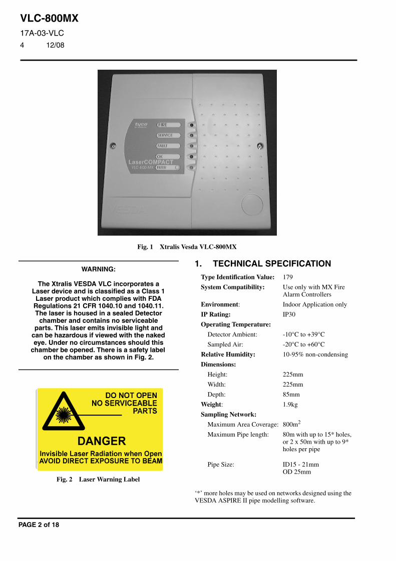
WARNING:
The Xtralis VESDA VLC incorporates a Laser device and is classified as a Class 1 Laser product which complies with FDA
Regulations 21 CFR 1040.10 and 1040.11. The laser is housed in a sealed Detector
chamber and contains no serviceable parts. This laser emits invisible light and
can be hazardous if viewed with the naked eye. Under no circumstances should this
chamber be opened. There is a safety label on the chamber as shown in Fig. 2.
Fig. 2 Laser Warning Label
PAGE 2 of 18
1. TECHNICAL SPECIFICATIONType Identification Value: 179
System Compatibility: Use only with MX FireAlarm Controllers
Environment: Indoor Application only
IP Rating: IP30
Operating Temperature:
Detector Ambient: -10°C to +39°C
Sampled Air: -20°C to +60°C
Relative Humidity: 10-95% non-condensing
Dimensions:
Height: 225mm
Width: 225mm
Depth: 85mm
Weight: 1.9kg
Sampling Network:
Maximum Area Coverage: 800m2
Maximum Pipe length: 80m with up to 15* holes,or 2 x 50m with up to 9*holes per pipe
Pipe Size: ID15 - 21mmOD 25mm
‘*’ more holes may be used on networks designed using theVESDA ASPIRE II pipe modelling software.
VLC-800MX17A-03-VLC4 12/08
EQUIPMENT:
PUBLICATION:
ISSUE No. & DATE:
Electrical Characteristics:
External 24V dc:
Supply Voltage: 18 to 30V dc
Current Consumption:
Standby: 225mA
Alarm: 245mA
Battery Requirements Addressable Loop:
Standby: 300μA
Non operational (VLC off): 300μA
Alarm: 300μA
Alarm with external relay: dependant on the relay
Alarm with external LED: 3.3mA
Fire relay: rated 2A @ 30V dc
Electromagnetic Compatibility:
The VLC-800MX complies with the following:
Product standard EN 54-20:2006, Fire detection and firealarm systems Part 20: Aspirating Smoke Detectors.Product family standard EN50130-4/A1/A2:2003 inrespect of EMC immunity
Generic standard EN 61000-6-3:2007 in respect of EMCemissions
© 2008 Tyco Safety Products
Registered Company: Thorn Security Ltd. Registered Office: Dun
2. INTRODUCTIONThe VLC-800MX is a derivative of the standard XtralisVESDA product family, with the primary difference beingthat it communicates directly on the MX loop.
VESDA VLC detectors provide Very Early Warning ofpotential fire conditions by drawing air samples through25mm pipe up to 80m long. Smoke is sampled throughholes in the pipe and transported to the detector by anintegrated aspirator or fan. Holes are positioned accordingto the application and often follow the spacing of standardconventional point detectors. Where necessary, samplingpoints can be constructed using capillary extensions. SeeSection 4, Sampling Pipework for more information.
The MX version of the VESDA VLC acts as a smoke sensoron the Tyco MX loop and reports directly to the MXcontroller.
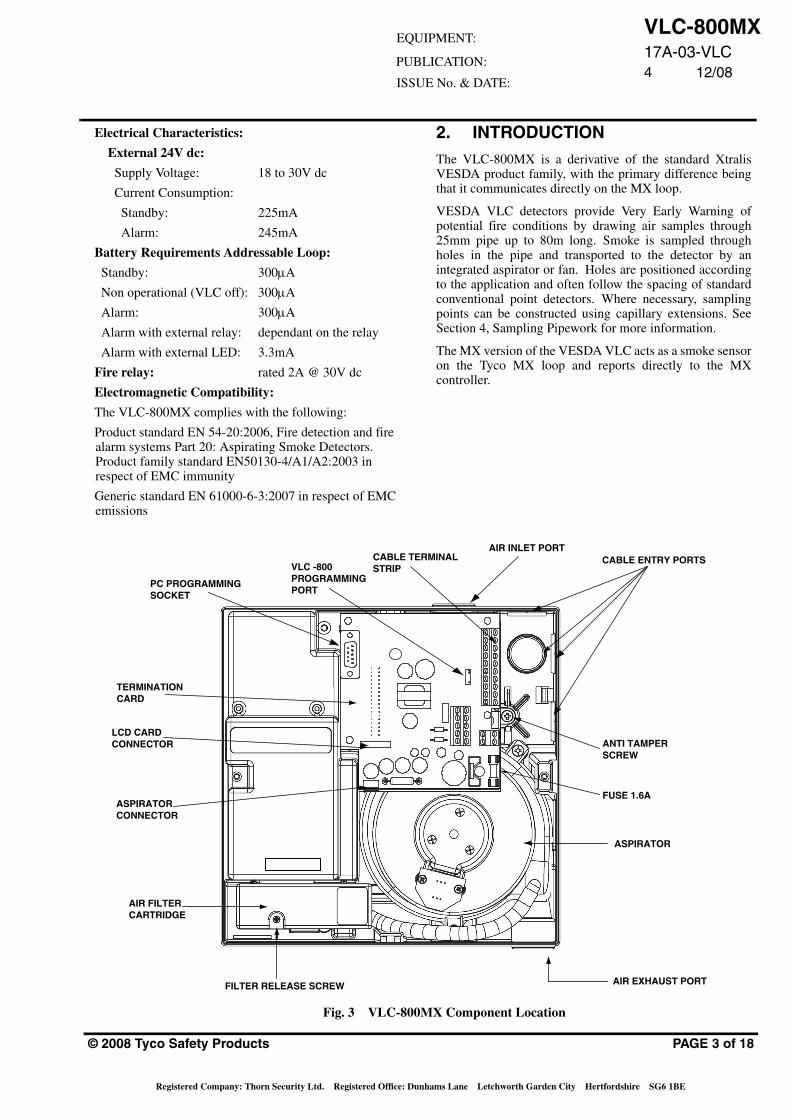
PC PROGRAMMINGSOCKET
TERMINATIONCARD
LCD CARDCONNECTOR
ASPIRATORCONNECTOR
AIR FILTERCARTRIDGE
FILTER RELEASE SCREW AIR EXHAUST PORT
ASPIRATOR
FUSE 1.6A
ANTI TAMPERSCREW
CABLE ENTRY PORTSAIR INLET PORT
CABLE TERMINALSTRIPVLC -800
PROGRAMMINGPORT
Fig. 3 VLC-800MX Component Location
PAGE 3 of 18
hams Lane Letchworth Garden City Hertfordshire SG6 1BE
VLC-800MX17A-03-VLC
4 12/08
PAGE 4 of 18
2.1 SCOPE OF THIS DOCUMENT
This manual provides instructions on how to install,commission and operate the VESDA VLC-800MX. It outlinesthe standard pipe configurations permissible, power supplyrequirements, and some installation tips. It does not provideinformation on how to design and verify customised pipe workconfigurations using the VESDA ASPIRE II pipe modellingsoftware and does not include detailed step-by-step installationinstructions.
This document provides brief details on how VSC (VESDASystem Configurator) is used to configure the detector. It doesnot describe how to use VESDA VSC PC based software toconfigure custom alarm thresholds, interrogate event logs andsmoke trends stored in the detector, set the internal clock andgenerally access the extensive features of the LaserCOMPACTdetector.
This document is intended for proficient installation engineerswho are familiar with the commissioning of an MX FireDetection System but have limited experience with theinstallation of VESDA Aspirating Smoke Detectors.
3. OPERATIONIn normal operation, the VLC-800MX is polled every 5seconds for the current smoke reading. This is scaled such thata zero reading is reported as 12 and a measurement equatingthe Fire threshold configured in the VLC is reported as 112. Ifthe value exceeds 112 for three consecutive polls, the MXpanel reports the condition as an alarm and commands the FireLED on the VLC to illuminate. A value exceeding 82 may bereported as a Pre-alarm condition by the MX panel. In additionto the poll every 5 seconds, the MX panel also polls the VLCfor its fault status every 20 seconds.
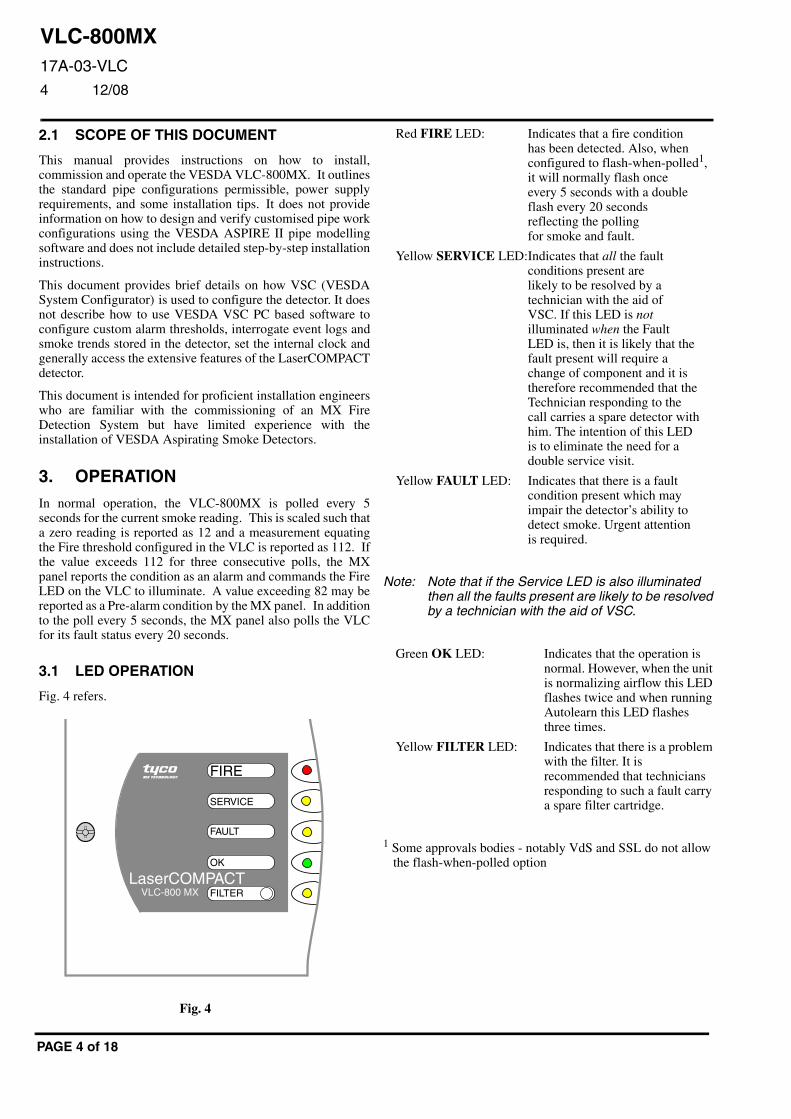
3.1 LED OPERATION
Fig. 4 refers.
LaserCOMPACTVLC-800 MX
tyco
FILTER
OK
FAULT
SERVICE
FIREMX TECHNOLOGY
Fig. 4
N
1
Red FIRE LED: Indicates that a fire conditionhas been detected. Also, whenconfigured to flash-when-polled1,it will normally flash onceevery 5 seconds with a doubleflash every 20 secondsreflecting the pollingfor smoke and fault.
Yellow SERVICE LED:Indicates that all the faultconditions present arelikely to be resolved by atechnician with the aid ofVSC. If this LED is notilluminated when the FaultLED is, then it is likely that thefault present will require achange of component and it istherefore recommended that theTechnician responding to thecall carries a spare detector withhim. The intention of this LEDis to eliminate the need for adouble service visit.
Yellow FAULT LED: Indicates that there is a faultcondition present which mayimpair the detector’s ability todetect smoke. Urgent attentionis required.
ote: Note that if the Service LED is also illuminatedthen all the faults present are likely to be resolvedby a technician with the aid of VSC.
Green OK LED: Indicates that the operation isnormal. However, when the unitis normalizing airflow this LEDflashes twice and when runningAutolearn this LED flashesthree times.
Yellow FILTER LED: Indicates that there is a problemwith the filter. It isrecommended that techniciansresponding to such a fault carrya spare filter cartridge.
Some approvals bodies - notably VdS and SSL do not allow the flash-when-polled option
VLC-800MX17A-03-VLC4 12/08
EQUIPMENT:
PUBLICATION:
ISSUE No. & DATE:
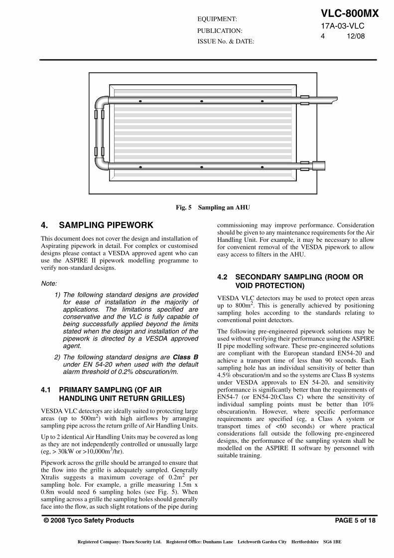
Fig. 5 Sampling an AHU
4. SAMPLING PIPEWORKThis document does not cover the design and installation ofAspirating pipework in detail. For complex or customiseddesigns please contact a VESDA approved agent who canuse the ASPIRE II pipework modelling programme toverify non-standard designs.
Note:
1) The following standard designs are providedfor ease of installation in the majority ofapplications. The limitations specified areconservative and the VLC is fully capable ofbeing successfully applied beyond the limitsstated when the design and installation of thepipework is directed by a VESDA approvedagent.
2) The following standard designs are Class Bunder EN 54-20 when used with the defaultalarm threshold of 0.2% obscuration/m.
4.1 PRIMARY SAMPLING (OF AIRHANDLING UNIT RETURN GRILLES)
VESDA VLC detectors are ideally suited to protecting largeareas (up to 500m2) with high airflows by arrangingsampling pipe across the return grille of Air Handling Units.
Up to 2 identical Air Handling Units may be covered as longas they are not independently controlled or unusually large(eg, > 30kW or >10,000m3/hr).
Pipework across the grille should be arranged to ensure thatthe flow into the grille is adequately sampled. GenerallyXtralis suggests a maximum coverage of 0.2m2 persampling hole. For example, a grille measuring 1.5m x0.8m would need 6 sampling holes (see Fig. 5). Whensampling across a grille the sampling holes should generallyface into the flow, as such slight rotations of the pipe during
© 2008 Tyco Safety Products
Registered Company: Thorn Security Ltd. Registered Office: Dun
commissioning may improve performance. Considerationshould be given to any maintenance requirements for the AirHandling Unit. For example, it may be necessary to allowfor convenient removal of the VESDA pipework to alloweasy access to filters in the AHU.
4.2 SECONDARY SAMPLING (ROOM ORVOID PROTECTION)
VESDA VLC detectors may be used to protect open areasup to 800m2. This is generally achieved by positioningsampling holes according to the standards relating toconventional point detectors.
The following pre-engineered pipework solutions may beused without verifying their performance using the ASPIREII pipe modelling software. These pre-engineered solutionsare compliant with the European standard EN54-20 andachieve a transport time of less than 90 seconds. Eachsampling hole has an individual sensitivity of better than4.5% obscuration/m and so the systems are Class B systemsunder VESDA approvals to EN 54-20. and sensitivityperformance is significantly better than the requirements ofEN54-7 (or EN54-20:Class C) where the sensitivity ofindividual sampling points must be better than 10%obscuration/m. However, where specific performancerequirements are specified (eg, a Class A system ortransport times of <60 seconds) or where practicalconsiderations fall outside the following pre-engineereddesigns, the performance of the sampling system shall bemodelled on the ASPIRE II software by personnel withsuitable training.
PAGE 5 of 18
hams Lane Letchworth Garden City Hertfordshire SG6 1BE
VLC-800MX17A-03-VLC
4 12/08
MAXIMUM PIPE LENGTH 80m
4mm END HOLE
3-15 OFF 2.5mm SAMPLING HOLES
2 OFF 4MM END HOLES
MAXIMUM PIPE LENGTH 50m
2-9 OFF 3mm SAMPLING HOLES (PER PIPE)
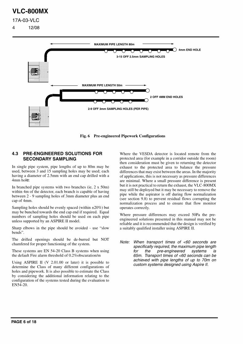
Fig. 6 Pre-engineered Pipework Configurations
4.3 PRE-ENGINEERED SOLUTIONS FORSECONDARY SAMPLING
In single pipe system, pipe lengths of up to 80m may beused, between 3 and 15 sampling holes may be used; eachhaving a diameter of 2.5mm with an end cap drilled with a4mm hole:
In branched pipe systems with two branches (ie, 2 x 50m)within 4m of the detector, each branch is capable of havingbetween 2 - 9 sampling holes of 3mm diameter plus an endcap of 4mm.
Sampling holes should be evenly spaced (within ±20%) butmay be bunched towards the end cap end if required. Equalnumbers of sampling holes should be used on each pipeunless supported by an ASPIRE II model.
Sharp elbows in the pipe should be avoided - use “slowbends”.
The drilled openings should be de-burred but NOTchamfered for proper functioning of the system.
These systems are EN 54-20 Class B systems when usingthe default Fire alarm threshold of 0.2%obscuration/m
Using ASPIRE II (V 2.01.00 or later) it is possible todetermine the Class of many different configurations ofholes and pipework. It is also possible to estimate the Classby considering the additional information relating to theconfiguration of the systems tested during the evaluation toEN54-20.
PAGE 6 of 18
Where the VESDA detector is located remote from theprotected area (for example in a corridor outside the room)then consideration must be given to returning the detectorexhaust to the protected area to balance the pressuredifferences that may exist between the areas. In the majorityof applications, this is not necessary as pressure differencesare minimal. Where a small pressure difference is presentbut it is not practical to return the exhaust, the VLC-800MXmay still be deployed but it may be necessary to remove thepipe while the aspirator is off during flow normalization(see section 9.8) to prevent residual flows corrupting thenormalization process and to ensure that flow monitoroperates correctly.
Where pressure differences may exceed 50Pa the pre-engineered solutions presented in this manual may not bereliable and it is recommended that the design is verified bya suitably qualified installer using ASPIRE II.
Note: When transport times of <60 seconds arespecifically required, the maximum pipe lengthfor the pre-engineered systems is65m. Transport times of <60 seconds can beachieved with pipe lengths of up to 70m oncustom systems designed using Aspire II.
VLC-800MX17A-03-VLC4 12/08
EQUIPMENT:
PUBLICATION:
ISSUE No. & DATE:
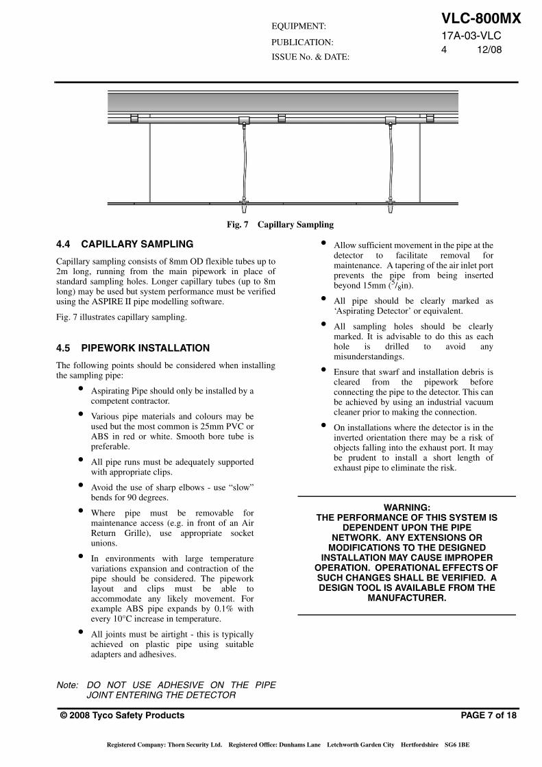
Fig. 7 Capillary Sampling
4.4 CAPILLARY SAMPLING
Capillary sampling consists of 8mm OD flexible tubes up to2m long, running from the main pipework in place ofstandard sampling holes. Longer capillary tubes (up to 8mlong) may be used but system performance must be verifiedusing the ASPIRE II pipe modelling software.
Fig. 7 illustrates capillary sampling.
4.5 PIPEWORK INSTALLATION
The following points should be considered when installingthe sampling pipe:
• Aspirating Pipe should only be installed by acompetent contractor.
• Various pipe materials and colours may beused but the most common is 25mm PVC orABS in red or white. Smooth bore tube ispreferable.
• All pipe runs must be adequately supportedwith appropriate clips.
• Avoid the use of sharp elbows - use “slow”bends for 90 degrees.
• Where pipe must be removable formaintenance access (e.g. in front of an AirReturn Grille), use appropriate socketunions.
• In environments with large temperaturevariations expansion and contraction of thepipe should be considered. The pipeworklayout and clips must be able toaccommodate any likely movement. Forexample ABS pipe expands by 0.1% withevery 10°C increase in temperature.
• All joints must be airtight - this is typicallyachieved on plastic pipe using suitableadapters and adhesives.
Note: DO NOT USE ADHESIVE ON THE PIPEJOINT ENTERING THE DETECTOR
© 2008 Tyco Safety Products
Registered Company: Thorn Security Ltd. Registered Office: Dun
• Allow sufficient movement in the pipe at thedetector to facilitate removal formaintenance. A tapering of the air inlet portprevents the pipe from being insertedbeyond 15mm (5/8in).
• All pipe should be clearly marked as‘Aspirating Detector’ or equivalent.
• All sampling holes should be clearlymarked. It is advisable to do this as eachhole is drilled to avoid anymisunderstandings.
• Ensure that swarf and installation debris iscleared from the pipework beforeconnecting the pipe to the detector. This canbe achieved by using an industrial vacuumcleaner prior to making the connection.
• On installations where the detector is in theinverted orientation there may be a risk ofobjects falling into the exhaust port. It maybe prudent to install a short length ofexhaust pipe to eliminate the risk.
WARNING:THE PERFORMANCE OF THIS SYSTEM IS
DEPENDENT UPON THE PIPE NETWORK. ANY EXTENSIONS OR
MODIFICATIONS TO THE DESIGNED INSTALLATION MAY CAUSE IMPROPER
OPERATION. OPERATIONAL EFFECTS OF SUCH CHANGES SHALL BE VERIFIED. A DESIGN TOOL IS AVAILABLE FROM THE
MANUFACTURER.
PAGE 7 of 18
hams Lane Letchworth Garden City Hertfordshire SG6 1BE
VLC-800MX17A-03-VLC
4 12/08
E
112. 5
112. 5
205
95
225
225
MOUNTINGBRACKET
E = CABLE ENTRY POINT ON REAR OF ENCLOSURE
8mm FIXING HOLES
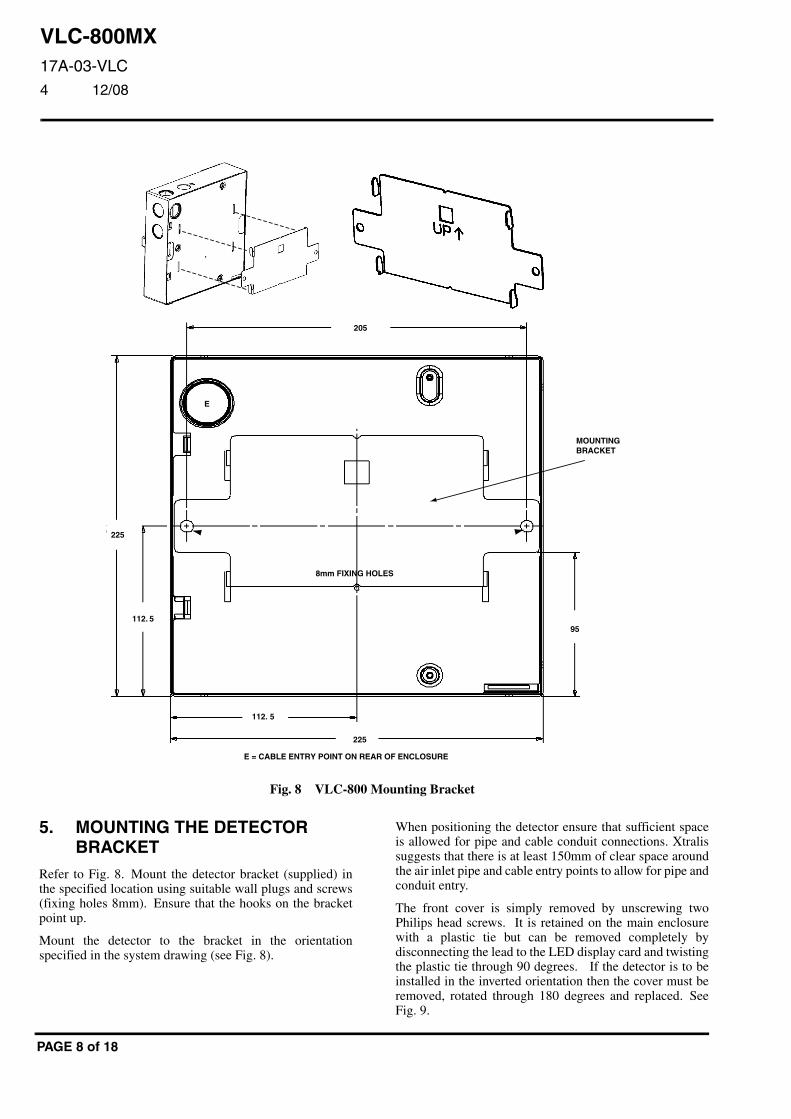
Fig. 8 VLC-800 Mounting Bracket
5. MOUNTING THE DETECTORBRACKET
Refer to Fig. 8. Mount the detector bracket (supplied) inthe specified location using suitable wall plugs and screws(fixing holes 8mm). Ensure that the hooks on the bracketpoint up.
Mount the detector to the bracket in the orientationspecified in the system drawing (see Fig. 8).
PAGE 8 of 18
When positioning the detector ensure that sufficient spaceis allowed for pipe and cable conduit connections. Xtralissuggests that there is at least 150mm of clear space aroundthe air inlet pipe and cable entry points to allow for pipe andconduit entry.
The front cover is simply removed by unscrewing twoPhilips head screws. It is retained on the main enclosurewith a plastic tie but can be removed completely bydisconnecting the lead to the LED display card and twistingthe plastic tie through 90 degrees. If the detector is to beinstalled in the inverted orientation then the cover must beremoved, rotated through 180 degrees and replaced. SeeFig. 9.
VLC-800MX17A-03-VLC4 12/08
EQUIPMENT:
PUBLICATION:
ISSUE No. & DATE:
CABLE ENTRY (ONEENTRY ON REAR OFENCLOSURE NOT SHOWN)
AIR INLET PORTAIR EXHAUSTPORT
CABLE ENTRY
AIR EXHAUST PORT
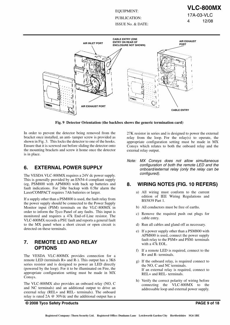
Fig. 9 Detector Orientation (the backbox shows the generic termination card)
In order to prevent the detector being removed from thebracket once installed, an anti- tamper screw is provided asshown in Fig. 3. This locks the detector to one of the hooks.Ensure that it is screwed out before sliding the detector ontothe mounting brackets and screw it home once the detectoris in place.
6. EXTERNAL POWER SUPPLYThe VESDA VLC-800MX requires a 24V dc power supply.This is generally provided by an EN54-4 compliant supply(eg, PSM800 with APM800) with back up batteries andfault indications. For 24hr backup with 0.5hr alarm theLaserCOMPACT requires 7Ah batteries or larger.
If a supply other than a PSM800 is used, the fault relay fromthe power supply should be connected to the Power SupplyMonitor input (PSM) terminals on the VLC-800MX inorder to inform the Tyco Panel of any faults. This input ismonitored and requires a 47k End-of-Line resistor. TheVLC-800MX records a PSU fault and reports a general faultto the MX panel when a short circuit or open circuit isdetected on these terminals.
7. REMOTE LED AND RELAYOPTIONS
The VESDA VLC-800MX provides connection for aremote LED (terminals R+ and R-). This output has a 3K6series resistor and is designed to power an LED directly(powered by the loop). For it to be illuminated on Fire, theappropriate configuration setting must be made in MXConsys.
The VLC-800MX also provides an onboard relay (NO, Cand NC terminals) and an additional output to drive anexternal relay (REL+ and REL- terminals). The onboardrelay is rated 2A @ 30Vdc and the additional output has a
© 2008 Tyco Safety Products
Registered Company: Thorn Security Ltd. Registered Office: Dun
27K resistor in series and is designed to power the externalrelay from the loop. For the relay(s) to operate, theappropriate configuration setting must be made in MXConsys which relates to both the onboard relay and theexternal relay output.
Note: MX Consys does not allow simultaneousconfiguration of both the remote LED and theonboard/external relay (only the relay can beconfigured).
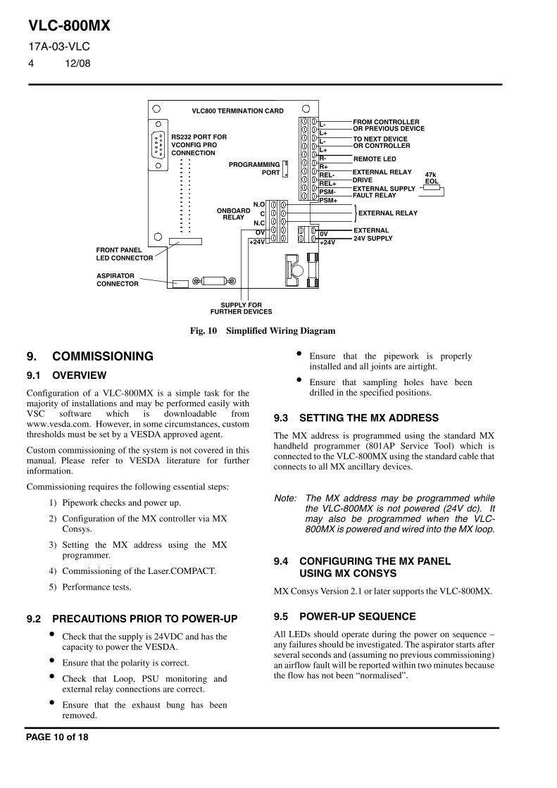
8. WIRING NOTES (FIG. 10 REFERS)a) All wiring must conform to the current
edition of IEE Wiring Regulations andBS5839 Part 1.
b) All conductors must be free of earths.
c) Remove the required push out plugs forcable entry.
d) Run all cables and gland off as necessary.
e) If a power supply other than a PSM800 withAPM800 is used, connect the power supplyfault relay to the PSM+ and PSM- terminalswith a 47k EOL.
f) If a remote LED is required, connect to theR+ and R- terminals.
g) If the onboard relay, is required connect tothe NO, C and NC terminals.If an external relay is required, connect toREL+ and REL- terminals.
h) Verify the correct polarity of wiring beforeconnecting the VLC-800MX to theaddressable loop and external power supply.
PAGE 9 of 18
hams Lane Letchworth Garden City Hertfordshire SG6 1BE
VLC-800MX17A-03-VLC
4 12/08
RS232 PORT FORVCONFIG PROCONNECTION
VLC800 TERMINATION CARD
L-L+L-L+R-R+REL-REL+PSM-PSM+
0V+24V
N.OC
N.COV
+24V
EXTERNAL24V SUPPLY
EXTERNAL SUPPLYFAULT RELAY
47kEOL
FROM CONTROLLEROR PREVIOUS DEVICE
TO NEXT DEVICEOR CONTROLLER
REMOTE LED
ONBOARDRELAY
SUPPLY FORFURTHER DEVICES
EXTERNAL RELAYDRIVE
EXTERNAL RELAY}
FRONT PANELLED CONNECTOR
ASPIRATORCONNECTOR
PROGRAMMINGPORT
Fig. 10 Simplified Wiring Diagram
9. COMMISSIONING
9.1 OVERVIEW
Configuration of a VLC-800MX is a simple task for themajority of installations and may be performed easily withVSC software which is downloadable fromwww.vesda.com. However, in some circumstances, customthresholds must be set by a VESDA approved agent.
Custom commissioning of the system is not covered in thismanual. Please refer to VESDA literature for furtherinformation.
Commissioning requires the following essential steps:
1) Pipework checks and power up.
2) Configuration of the MX controller via MXConsys.
3) Setting the MX address using the MXprogrammer.
4) Commissioning of the Laser.COMPACT.
5) Performance tests.
9.2 PRECAUTIONS PRIOR TO POWER-UP
• Check that the supply is 24VDC and has thecapacity to power the VESDA.
• Ensure that the polarity is correct.
• Check that Loop, PSU monitoring andexternal relay connections are correct.
• Ensure that the exhaust bung has beenremoved.
PAGE 10 of 18
• Ensure that the pipework is properlyinstalled and all joints are airtight.
• Ensure that sampling holes have beendrilled in the specified positions.
9.3 SETTING THE MX ADDRESS
The MX address is programmed using the standard MXhandheld programmer (801AP Service Tool) which isconnected to the VLC-800MX using the standard cable thatconnects to all MX ancillary devices.
Note: The MX address may be programmed whilethe VLC-800MX is not powered (24V dc). Itmay also be programmed when the VLC-800MX is powered and wired into the MX loop.
9.4 CONFIGURING THE MX PANELUSING MX CONSYS
MX Consys Version 2.1 or later supports the VLC-800MX.
9.5 POWER-UP SEQUENCE
All LEDs should operate during the power on sequence –any failures should be investigated. The aspirator starts afterseveral seconds and (assuming no previous commissioning)an airflow fault will be reported within two minutes becausethe flow has not been “normalised”.
VLC-800MX17A-03-VLC4 12/08
EQUIPMENT:
PUBLICATION:
ISSUE No. & DATE:
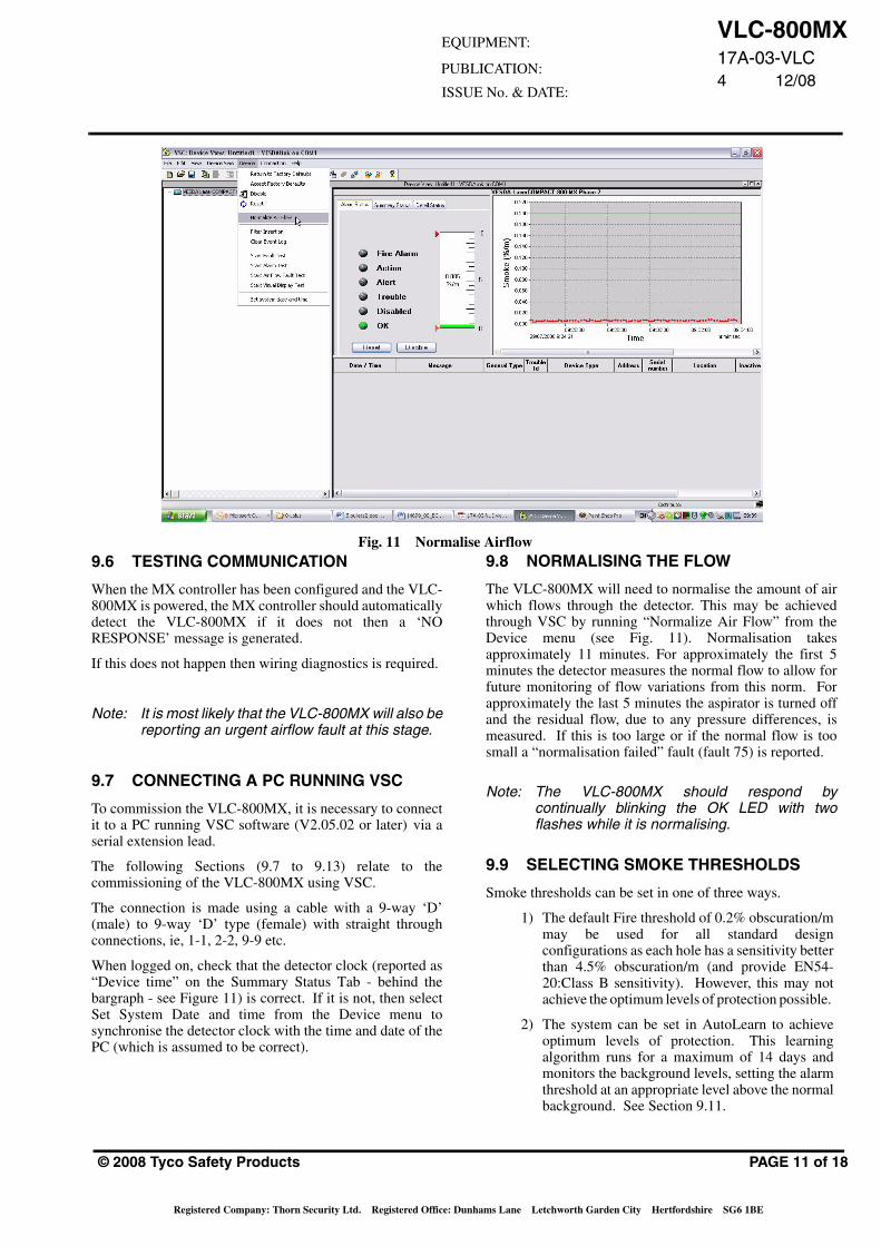
Fig. 11 Normalise Airflow9.6 TESTING COMMUNICATION 9.8 NORMALISING THE FLOW
When the MX controller has been configured and the VLC-800MX is powered, the MX controller should automaticallydetect the VLC-800MX if it does not then a ‘NORESPONSE’ message is generated.
If this does not happen then wiring diagnostics is required.
Note: It is most likely that the VLC-800MX will also bereporting an urgent airflow fault at this stage.
9.7 CONNECTING A PC RUNNING VSC
To commission the VLC-800MX, it is necessary to connectit to a PC running VSC software (V2.05.02 or later) via aserial extension lead.
The following Sections (9.7 to 9.13) relate to thecommissioning of the VLC-800MX using VSC.
The connection is made using a cable with a 9-way ‘D’(male) to 9-way ‘D’ type (female) with straight throughconnections, ie, 1-1, 2-2, 9-9 etc.
When logged on, check that the detector clock (reported as“Device time” on the Summary Status Tab - behind thebargraph - see Figure 11) is correct. If it is not, then selectSet System Date and time from the Device menu tosynchronise the detector clock with the time and date of thePC (which is assumed to be correct).
© 2008 Tyco Safety Products
Registered Company: Thorn Security Ltd. Registered Office: Dun
The VLC-800MX will need to normalise the amount of airwhich flows through the detector. This may be achievedthrough VSC by running “Normalize Air Flow” from theDevice menu (see Fig. 11). Normalisation takesapproximately 11 minutes. For approximately the first 5minutes the detector measures the normal flow to allow forfuture monitoring of flow variations from this norm. Forapproximately the last 5 minutes the aspirator is turned offand the residual flow, due to any pressure differences, ismeasured. If this is too large or if the normal flow is toosmall a “normalisation failed” fault (fault 75) is reported.
Note: The VLC-800MX should respond bycontinually blinking the OK LED with twoflashes while it is normalising.
9.9 SELECTING SMOKE THRESHOLDS
Smoke thresholds can be set in one of three ways.
1) The default Fire threshold of 0.2% obscuration/mmay be used for all standard designconfigurations as each hole has a sensitivity betterthan 4.5% obscuration/m (and provide EN54-20:Class B sensitivity). However, this may notachieve the optimum levels of protection possible.
2) The system can be set in AutoLearn to achieveoptimum levels of protection. This learningalgorithm runs for a maximum of 14 days andmonitors the background levels, setting the alarmthreshold at an appropriate level above the normalbackground. See Section 9.11.
PAGE 11 of 18
hams Lane Letchworth Garden City Hertfordshire SG6 1BE
VLC-800MX17A-03-VLC
4 12/08
3) Customised thresholds can be set using aPC running VLC.
Customised thresholds may be appropriate in particularcircumstances but should be used with caution. Forexample, the default alarm threshold of 0.2% may beinappropriate for a system protecting a small area (usingfewer holes than the maximum allowed) with a backgroundlevel around 0.15% obscuration/m. In this situation a Firethreshold > 0.2% obscuration/m may be appropriate.
However, as a general rule, the maximum Alarm thresholdneeded to ensure a given EN54-20 sensitivity Class is givenby the following expression:
Class C threshold < 6/ N % obscuration/m
Class B threshold < 3 / N % obscuration/m
Class A threshold < 1 / N % obscuration/m
(where N = total number of holes; sampling holes +endcap)
Note: These rule of thumb expressions are onlyrelevant to the Pre-engineered designspresented in this manual. They are notrelevant to pipe configurations designed by anapproved VESDA agent and verified using theAspire pipe modelling software.
9.10 PRE-ALRM AND ALARM DELAYS
The VLC-800MX supports Pre-alarm processing such thatif the analogue reading exceeds 82 for two consecutivepolls, the MX panel will report a pre-alarm condition. Ifthe analogue reading exceeds 112 for three consecutivepolls, then an alarm condition is reported. Any additionaldelays to signalling or acting on the alarm condition may beconfigured in MX Consys. There are no configurabledelays specific to the VLC-800MX.
PAGE 12 of 18
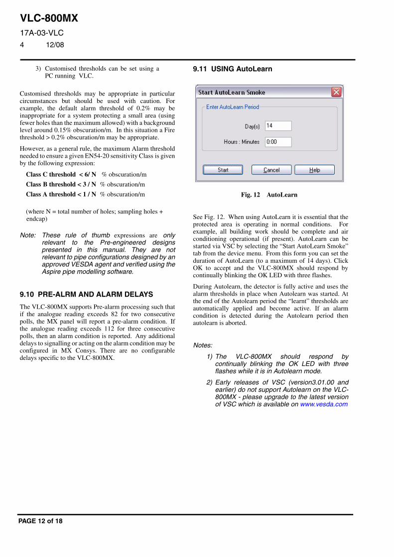
9.11 USING AutoLearn
See Fig. 12. When using AutoLearn it is essential that theprotected area is operating in normal conditions. Forexample, all building work should be complete and airconditioning operational (if present). AutoLearn can bestarted via VSC by selecting the “Start AutoLearn Smoke”tab from the device menu. From this form you can set theduration of AutoLearn (to a maximum of 14 days). ClickOK to accept and the VLC-800MX should respond bycontinually blinking the OK LED with three flashes.
During Autolearn, the detector is fully active and uses thealarm thresholds in place when Autolearn was started. Atthe end of the Autolearn period the “learnt” thresholds areautomatically applied and become active. If an alarmcondition is detected during the Autolearn period thenautolearn is aborted.
Notes:
1) The VLC-800MX should respond bycontinually blinking the OK LED with threeflashes while it is in Autolearn mode.
2) Early releases of VSC (version3.01.00 andearlier) do not support Autolearn on the VLC-800MX - please upgrade to the latest versionof VSC which is available on www.vesda.com
Fig. 12 AutoLearn
VLC-800MX17A-03-VLC4 12/08
EQUIPMENT:
PUBLICATION:
ISSUE No. & DATE:
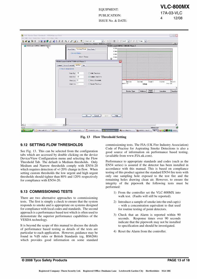
Fig. 13 Flow Threshold Setting
9.12 SETTING FLOW THRESHOLDS
See Fig. 13. This can be selected from the configurationtabs which are accessed by double clicking on the deviceDevice/View Configuration menu and selecting the FlowThreshold Tab. The default is Medium thresholds. OnlyMedium and Narrow thresholds comply with EN54-20which requires detection of +/-20% change in flow. Whensetting custom thresholds the low urgent and high urgentthresholds should tighter than 80% and 120% respectivelyfor compliance with EN54-20.
9.13 COMMISSIONING TESTS
There are two alternative approaches to commissioningtests. The first is simply a check to ensure that the systemresponds to smoke and is appropriate on systems designedfor compliance with local codes and standards. The secondapproach is a performance based test which is often used todemonstrate the superior performance capabilities of theVESDA technology.
It is beyond the scope of this manual to discuss the detailsof performance based testing as details of the tests areparticular to each application. However, guidance may befound in VdS rules or British Standards (eg, BS6266)which provides good information on some standard
© 2008 Tyco Safety Products
Registered Company: Thorn Security Ltd. Registered Office: D
commissioning tests. The FIA (UK Fire Industry Association)Code of Practise for Aspirating Smoke Detections is also agood source of information on performance based testing.(available from www.FIA.uk.com).
Performance to appropriate standards and codes (such as theEN54 series) is assured if the detector has been installed inaccordance with this manual. This is based on compliancetesting of this product against the standard EN54 fire tests withonly one sampling hole exposed to the test fire and theremaining holes drawing clean air. However, to ensure theintegrity of the pipework the following tests must beperformed:
1) From the controller set the VLC-800MX intowalk test. (Faults will still be reported).
2) Introduce a sample of smoke into the end cap(s)– with a concentration equivalent to that usedfor routine testing of point detectors.
3) Check that an Alarm is reported within 90seconds. Response times over 90 secondsindicate that the pipework may not be installedto specification and should be investigated.
4) Reset the Alarm from the controller.
PAGE 13 of 18
unhams Lane Letchworth Garden City Hertfordshire SG6 1BE
VLC-800MX17A-03-VLC
4 12/08
Action Frequency Details
Check Power supplies Every month Test according to suppliers instructions. Note: Where the condition of the battery is regularly checked automatically, less frequent manual checks may be applicable.
Check the pipework Every 6 months Check that all pipe runs are intact, that pipe supports and joints are firm and that the sampling holes are free of dirt.
Check air flows Every year Check logs to verify that no airflow faults have occurred. Where possible use VConfig to read the airflow readings (including the raw airflow readings). Any sign of drift should be investigated.
Check Filter Every year Check that there are no filter faults (where possible use VConfig Pro to read the current filter counts).
Change Filter Every 2 years Fit a new filter cartridge regularly depending on the relative cleanliness of the protected environment. Eg, every 2 years in a normal environment, up to 5 years in a clean, air conditioned computer room or every year or less in an area exposed to a dusty or smokey atmosphere.
Smoke test Every year Set the detector into Walk Test mode and introduce smoke into the end cap (see commissioning). Compare response times with those previously recorded and investigate any discrepancies.
Flush sampling points Every 2 years Isolate the detector, remove pipe from the inlet port and connect a vacuum cleaner. Run the cleaner for several minutes.
Clean sampling points As necessary If flushing does not clear the sampling points then they must be physically cleared.
Table. 1 Maintenance Schedule
5) Carefully check each sampling hole (usingfield glasses if necessary). Introduce smokeinto any that cannot be inspected and into atleast 10% of the holes. Check that an Alarmis reported at the VLC-800MX in each case.
6) Record all results for future reference –particularly the response time from the endcap(s) and the raw flow reading.
10. MAINTENANCE
10.1 OVERVIEW
The VESDA VLC-800MX requires little regularmaintenance as the majority of potential failures aremonitored.
There are only two serviceable items; the filter cartridge andthe aspirator.
On no account should the rear cover of the detector beremoved as this may invalidate the warranty.
10.2 SCHEDULE
Table 1 details the maintenance schedule necessary tomaintain the VESDA VLC-800MX in peak working orderin the majority of applications.
PAGE 14 of 18
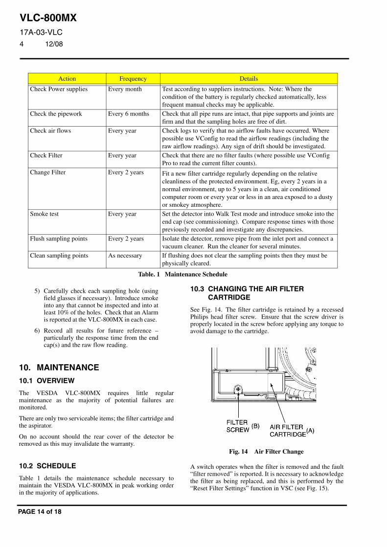
10.3 CHANGING THE AIR FILTERCARTRIDGE
See Fig. 14. The filter cartridge is retained by a recessedPhilips head filter screw. Ensure that the screw driver isproperly located in the screw before applying any torque toavoid damage to the cartridge.
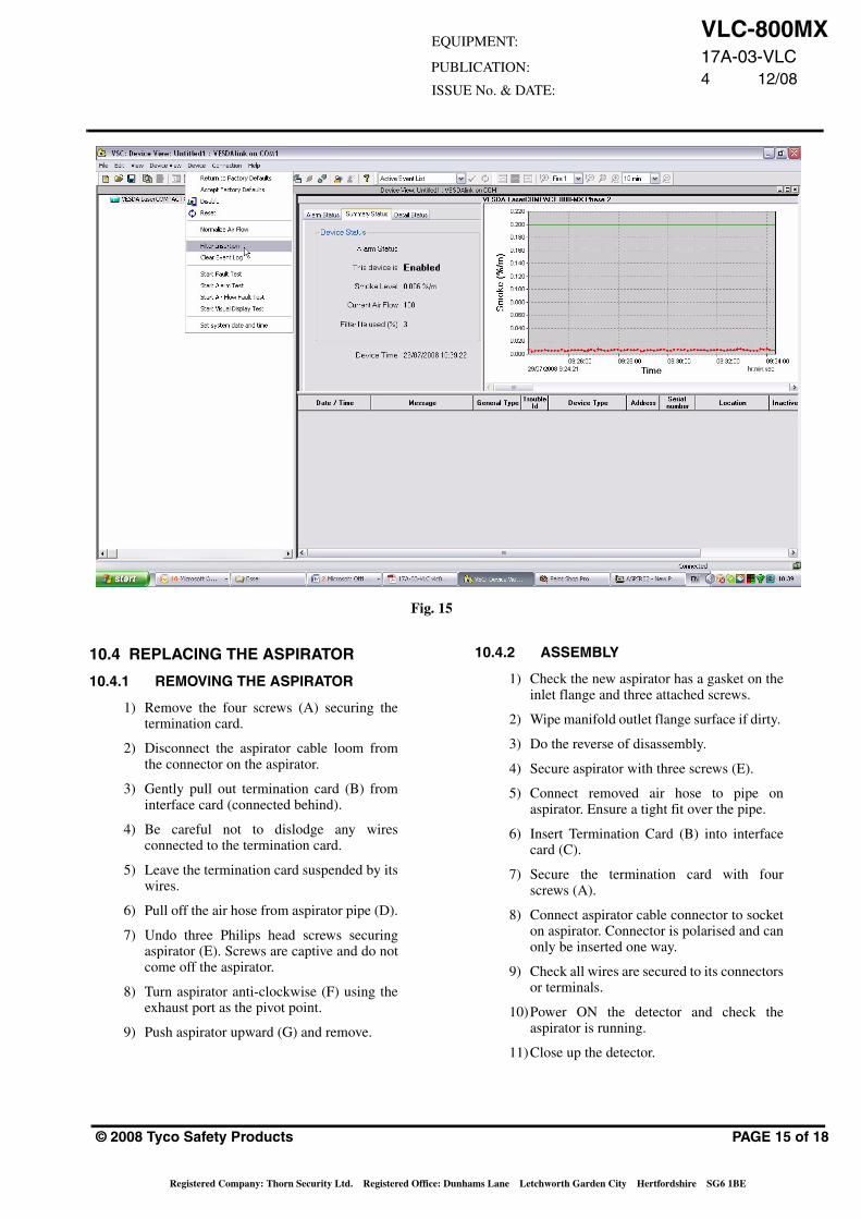
A switch operates when the filter is removed and the fault“filter removed” is reported. It is necessary to acknowledgethe filter as being replaced, and this is performed by the“Reset Filter Settings” function in VSC (see Fig. 15).
Fig. 14 Air Filter Change
VLC-800MX17A-03-VLC4 12/08
EQUIPMENT:
PUBLICATION:
ISSUE No. & DATE:
Fig. 15
10.4 REPLACING THE ASPIRATOR
10.4.1 REMOVING THE ASPIRATOR
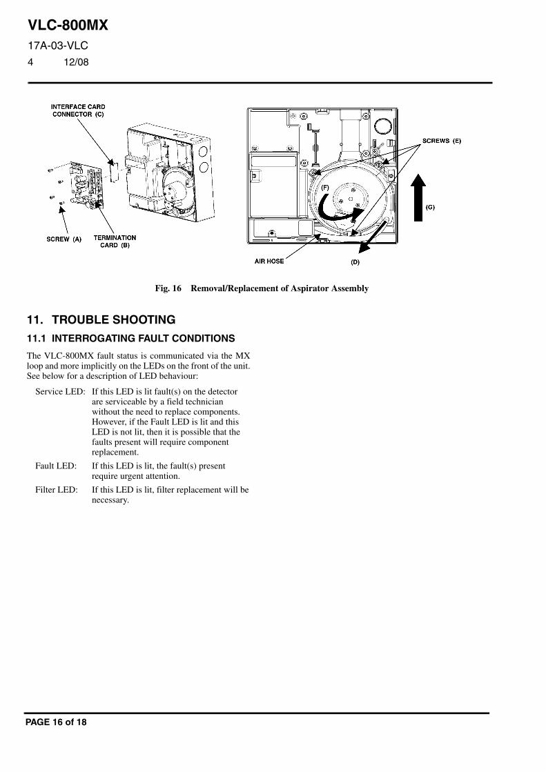
1) Remove the four screws (A) securing thetermination card.
2) Disconnect the aspirator cable loom fromthe connector on the aspirator.
3) Gently pull out termination card (B) frominterface card (connected behind).
4) Be careful not to dislodge any wiresconnected to the termination card.
5) Leave the termination card suspended by itswires.
6) Pull off the air hose from aspirator pipe (D).
7) Undo three Philips head screws securingaspirator (E). Screws are captive and do notcome off the aspirator.
8) Turn aspirator anti-clockwise (F) using theexhaust port as the pivot point.
9) Push aspirator upward (G) and remove.
© 2008 Tyco Safety Products
Registered Company: Thorn Security Ltd. Registered Office: Dun
10.4.2 ASSEMBLY
1) Check the new aspirator has a gasket on theinlet flange and three attached screws.
2) Wipe manifold outlet flange surface if dirty.
3) Do the reverse of disassembly.
4) Secure aspirator with three screws (E).
5) Connect removed air hose to pipe onaspirator. Ensure a tight fit over the pipe.
6) Insert Termination Card (B) into interfacecard (C).
7) Secure the termination card with fourscrews (A).
8) Connect aspirator cable connector to socketon aspirator. Connector is polarised and canonly be inserted one way.
9) Check all wires are secured to its connectorsor terminals.
10)Power ON the detector and check theaspirator is running.
11)Close up the detector.
PAGE 15 of 18
hams Lane Letchworth Garden City Hertfordshire SG6 1BE
VLC-800MX17A-03-VLC
4 12/08
Fig. 16 Removal/Replacement of Aspirator Assembly
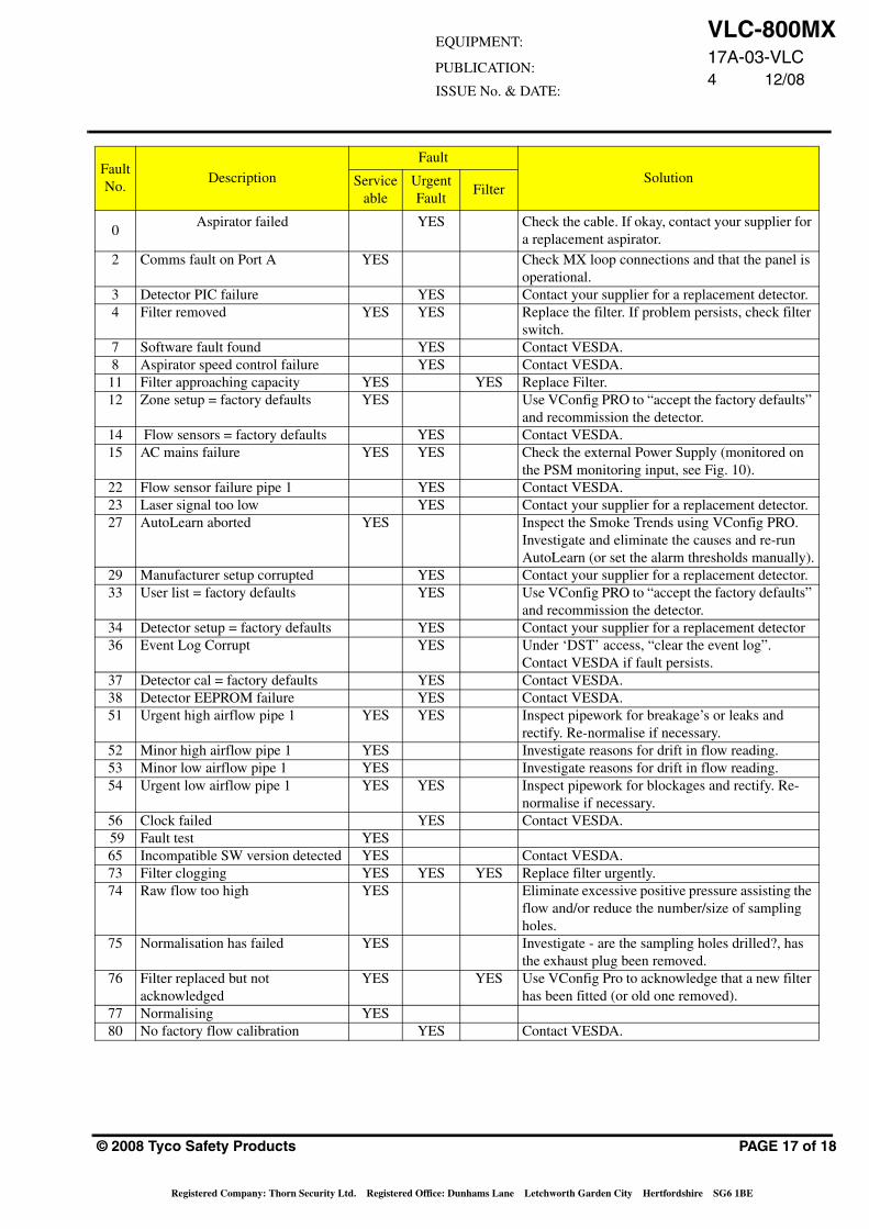
11. TROUBLE SHOOTING
11.1 INTERROGATING FAULT CONDITIONS
The VLC-800MX fault status is communicated via the MXloop and more implicitly on the LEDs on the front of the unit.See below for a description of LED behaviour:
Service LED: If this LED is lit fault(s) on the detectorare serviceable by a field technicianwithout the need to replace components.However, if the Fault LED is lit and thisLED is not lit, then it is possible that thefaults present will require componentreplacement.
Fault LED: If this LED is lit, the fault(s) presentrequire urgent attention.
Filter LED: If this LED is lit, filter replacement will benecessary.
PAGE 16 of 18
VLC-800MX17A-03-VLC4 12/08
EQUIPMENT:
PUBLICATION:
ISSUE No. & DATE:
Fault No.
Description
Fault
SolutionServiceable
Urgent Fault
Filter
0 Aspirator failed YES Check the cable. If okay, contact your supplier for
a replacement aspirator.
2 Comms fault on Port A YES Check MX loop connections and that the panel is operational.
3 Detector PIC failure YES Contact your supplier for a replacement detector. 4 Filter removed YES YES Replace the filter. If problem persists, check filter
switch. 7 Software fault found YES Contact VESDA.8 Aspirator speed control failure YES Contact VESDA.
11 Filter approaching capacity YES YES Replace Filter. 12 Zone setup = factory defaults YES Use VConfig PRO to “accept the factory defaults”
and recommission the detector.14 Flow sensors = factory defaults YES Contact VESDA.15 AC mains failure YES YES Check the external Power Supply (monitored on
the PSM monitoring input, see Fig. 10).22 Flow sensor failure pipe 1 YES Contact VESDA.23 Laser signal too low YES Contact your supplier for a replacement detector. 27 AutoLearn aborted YES Inspect the Smoke Trends using VConfig PRO.
Investigate and eliminate the causes and re-run AutoLearn (or set the alarm thresholds manually).
29 Manufacturer setup corrupted YES Contact your supplier for a replacement detector.33 User list = factory defaults YES Use VConfig PRO to “accept the factory defaults”
and recommission the detector.34 Detector setup = factory defaults YES Contact your supplier for a replacement detector 36 Event Log Corrupt YES Under ‘DST’ access, “clear the event log”.
Contact VESDA if fault persists.37 Detector cal = factory defaults YES Contact VESDA.38 Detector EEPROM failure YES Contact VESDA.51 Urgent high airflow pipe 1 YES YES Inspect pipework for breakage’s or leaks and
rectify. Re-normalise if necessary.52 Minor high airflow pipe 1 YES Investigate reasons for drift in flow reading.53 Minor low airflow pipe 1 YES Investigate reasons for drift in flow reading.54 Urgent low airflow pipe 1 YES YES Inspect pipework for blockages and rectify. Re-
normalise if necessary. 56 Clock failed YES Contact VESDA. 59 Fault test YES65 Incompatible SW version detected YES Contact VESDA.73 Filter clogging YES YES YES Replace filter urgently.74 Raw flow too high YES Eliminate excessive positive pressure assisting the
flow and/or reduce the number/size of sampling holes.
75 Normalisation has failed YES Investigate - are the sampling holes drilled?, has the exhaust plug been removed.
76 Filter replaced but not acknowledged
YES YES Use VConfig Pro to acknowledge that a new filter has been fitted (or old one removed).
77 Normalising YES80 No factory flow calibration YES Contact VESDA.
© 2008 Tyco Safety Products PAGE 17 of 18
Registered Company: Thorn Security Ltd. Registered Office: Dunhams Lane Letchworth Garden City Hertfordshire SG6 1BE
VLC-800MX17A-03-VLC
4 12/08
12. ORDERING INFORMATIONVLC-800MX VESDA Laser COMPACT: 516.018.012
Air Filter Cartridge: 516.018.504 Xtralis: VSP-005
Aspirator Fan: 516.018.515 Xtralis: VSP-015
VESDA 24V dc 2A Power Supply: 516.018.407 Xtralis: VSP-220
13. APPROVALSThe VLC-800MX is CE marked to the Construction Products Directive (CPD) supported by an EC Certificate of Conformity(0832-CPD-0770 issued by BRE Global) to EN 54-20. The VLC-800MX is approved by LPCB and VdS to EN 54-20 underXtralis AG certificate numbers 305b issue 8 and G203026 repectively.
JM/jm
3rd December 2008
PAGE 18 of 18