xrd basics
DESCRIPTION
Fundamentals of diffractionTRANSCRIPT

Page 7.1 © 1999 Scintag Inc. All Rights Reserved.
Chapter 7: Basics of X-ray Diffraction
Scintag has prepared this section for use by customers and authorized personnel.
The information contained herein is the property of Scintag and shall not be reproduced in whole or in part without Scintag prior written approval. Scintag reserves the right to make changes without notice in the specifications and materials contained herein and shall not be responsible for any damage (including consequential) caused by reliance on the material presented, including but not limited to typographical, arithmetic, or listing error.
Chapter 7: Basics of X-ray Diffraction
© S c i n t a g , I n c .
AII I - C
10040 Bubb Road Cupertino, CA 95014 U.S.A. www.scintag.com
Phone: 408-253-6100 Fax: 408-253-6300 Email: [email protected]
Providing Solutions To Your Diffraction Needs.
Page 7.2 © 1999 Scintag Inc. All Rights Reserved.
Chapter 7: Basics of X-ray Diffraction
Chapter cover page 7.1
Table of Contents 7.2
Introduction to Powder/Polycrystalline Diffraction 7.3
Theoretical Considerations 7.4
Samples 7.6
Goniometer 7.7
Diffractometer Slit System 7.9
Diffraction Spectra 7.10
ICDD Data base 7.11
Preferred Orientation 7.12
Applications 7.13
Texture Analysis 7.20
End of Chapter 7.25
TABLE OF CONTENTS

Page 7.3 © 1999 Scintag Inc. All Rights Reserved.
Chapter 7: Basics of X-ray Diffraction
INTRODUCTION TO POWDER/POLYCRYSTALLINE DIFFRACTION
About 95% of all solid materials can be described as crystalline. When X-rays interact with a crystalline substance (Phase), one gets a diffraction pattern. In 1919 A.W.Hull gave a paper titled, “A New Method of Chemical Analysis”. Here he pointed out that “… .every crystalline substance gives a pattern; the same substance always gives the same pattern; and in a mixture of substances each produces its pattern independently of the others. “ The X-ray diffraction pattern of a pure substance is, therefore, like a fingerprint of the substance. The powder dif-fraction method is thus ideally suited for characterization and identification of polycrystalline phases. Today about 50,000 inorganic and 25,000 organic single component, crystalline phases, diffraction patterns have been collected and stored on magnetic or optical media as standards. The main use of powder diffraction is to iden-tify components in a sample by a search/match procedure. Furthermore, the areas under the peak are related to the amount of each phase present in the sample.
Page 7.4 © 1999 Scintag Inc. All Rights Reserved.
Chapter 7: Basics of X-ray Diffraction
THEORETICAL CONSIDERATIONS
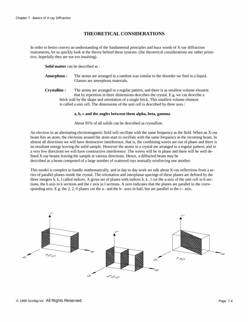
In order to better convey an understanding of the fundamental principles and buzz words of X-ray diffraction instruments, let us quickly look at the theory behind these systems. (the theoretical considerations are rather primi-tive, hopefully they are not too insulting). Solid matter can be described as : Amorphous : The atoms are arranged in a random way similar to the disorder we find in a liquid. Glasses are amorphous materials. Crystalline : The atoms are arranged in a regular pattern, and there is as smallest volume element that by repetition in three dimensions describes the crystal. E.g. we can describe a brick wall by the shape and orientation of a single brick. This smallest volume element is called a unit cell. The dimensions of the unit cell is described by three axes : a, b, c and the angles between them alpha, beta, gamma. About 95% of all solids can be described as crystalline. An electron in an alternating electromagnetic field will oscillate with the same frequency as the field. When an X-ray beam hits an atom, the electrons around the atom start to oscillate with the same frequency as the incoming beam. In almost all directions we will have destructive interference, that is, the combining waves are out of phase and there is no resultant energy leaving the solid sample. However the atoms in a crystal are arranged in a regular pattern, and in a very few directions we will have constructive interference. The waves will be in phase and there will be well de-fined X-ray beams leaving the sample at various directions. Hence, a diffracted beam may be described as a beam composed of a large number of scattered rays mutually reinforcing one another. This model is complex to handle mathematically, and in day to day work we talk about X-ray reflections from a se-ries of parallel planes inside the crystal. The orientation and interplanar spacings of these planes are defined by the three integers h, k, l called indices. A given set of planes with indices h, k , l cut the a-axis of the unit cell in h sec-tions, the b axis in k sections and the c axis in l sections. A zero indicates that the planes are parallel to the corre-sponding axis. E.g. the 2, 2, 0 planes cut the a– and the b– axes in half, but are parallel to the c– axis.
Page 7.5 © 1999 Scintag Inc. All Rights Reserved.
Chapter 7: Basics of X-ray Diffraction
THEORETICAL CONSIDERATIONS
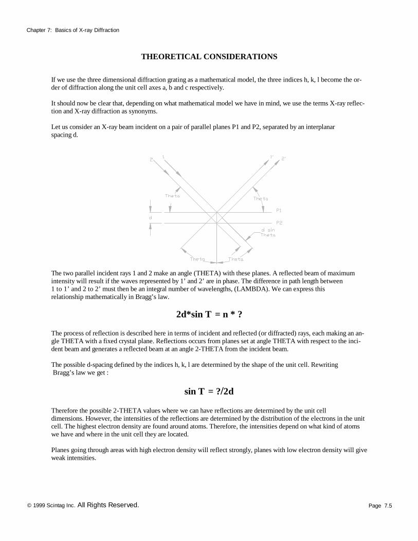
If we use the three dimensional diffraction grating as a mathematical model, the three indices h, k, l become the or-der of diffraction along the unit cell axes a, b and c respectively. It should now be clear that, depending on what mathematical model we have in mind, we use the terms X-ray reflec-tion and X-ray diffraction as synonyms. Let us consider an X-ray beam incident on a pair of parallel planes P1 and P2, separated by an interplanar spacing d.
The two parallel incident rays 1 and 2 make an angle (THETA) with these planes. A reflected beam of maximum intensity will result if the waves represented by 1’ and 2’ are in phase. The difference in path length between 1 to 1’ and 2 to 2’ must then be an integral number of wavelengths, (LAMBDA). We can express this relationship mathematically in Bragg’s law.
2d*sin T = n * ? The process of reflection is described here in terms of incident and reflected (or diffracted) rays, each making an an-gle THETA with a fixed crystal plane. Reflections occurs from planes set at angle THETA with respect to the inci-dent beam and generates a reflected beam at an angle 2-THETA from the incident beam. The possible d-spacing defined by the indices h, k, l are determined by the shape of the unit cell. Rewriting Bragg’s law we get :
sin T = ?/2d Therefore the possible 2-THETA values where we can have reflections are determined by the unit cell dimensions. However, the intensities of the reflections are determined by the distribution of the electrons in the unit cell. The highest electron density are found around atoms. Therefore, the intensities depend on what kind of atoms we have and where in the unit cell they are located. Planes going through areas with high electron density will reflect strongly, planes with low electron density will give weak intensities.
Page 7.6 © 1999 Scintag Inc. All Rights Reserved.
Chapter 7: Basics of X-ray Diffraction
SAMPLES
In X-ray diffraction work we normally distinguish between single crystal and polycrystalline or powder applications. The single crystal sample is a perfect (all unit cells aligned in a perfect extended pattern) crystal with a cross section of about 0.3 mm. The single crystal diffractometer and associated computer package is used mainly to elucidate the molecular structure of novel compounds, either natural products or man made molecules. Powder diffraction is mainly used for “finger print identification” of various solid materials, e.g. asbestos, quartz. In powder or polycrystalline diffraction it is important to have a sample with a smooth plane surface. If possible, we normally grind the sample down to particles of about 0.002 mm to 0.005 mm cross section. The ideal sample is ho-mogeneous and the crystallites are randomly distributed (we will later point out problems which will occur if the specimen deviates from this ideal state). The sample is pressed into a sample holder so that we have a smooth flat surface. Ideally we now have a random distribution of all possible h, k, l planes. Only crystallites having reflecting planes (h, k, l) parallel to the specimen surface will contribute to the reflected intensities. If we have a truly random sample, each possible reflection from a given set of h, k, l planes will have an equal number of crystallites contributing to it. We only have to rock the sample through the glancing angle THETA in order to produce all possi-ble reflections.
Page 7.7 © 1999 Scintag Inc. All Rights Reserved.
Chapter 7: Basics of X-ray Diffraction
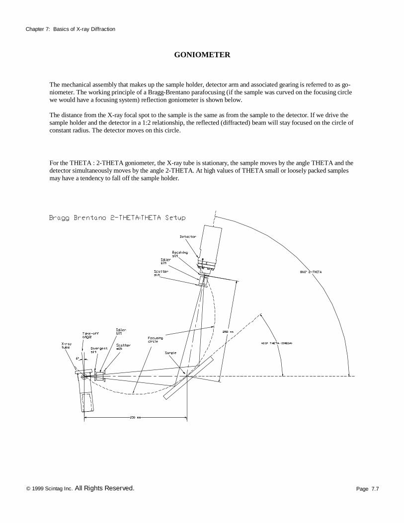
GONIOMETER
The mechanical assembly that makes up the sample holder, detector arm and associated gearing is referred to as go-niometer. The working principle of a Bragg-Brentano parafocusing (if the sample was curved on the focusing circle we would have a focusing system) reflection goniometer is shown below. The distance from the X-ray focal spot to the sample is the same as from the sample to the detector. If we drive the sample holder and the detector in a 1:2 relationship, the reflected (diffracted) beam will stay focused on the circle of constant radius. The detector moves on this circle.
For the THETA : 2-THETA goniometer, the X-ray tube is stationary, the sample moves by the angle THETA and the detector simultaneously moves by the angle 2-THETA. At high values of THETA small or loosely packed samples may have a tendency to fall off the sample holder.
Page 7.8 © 1999 Scintag Inc. All Rights Reserved.
Chapter 7: Basics of X-ray Diffraction
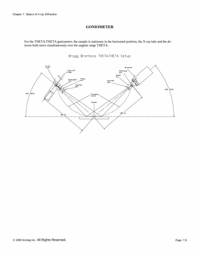
GONIOMETER
For the THETA:THETA goniometer, the sample is stationary in the horizontal position, the X-ray tube and the de-tector both move simultaneously over the angular range THETA.
Page 7.9 © 1999 Scintag Inc. All Rights Reserved.
Chapter 7: Basics of X-ray Diffraction
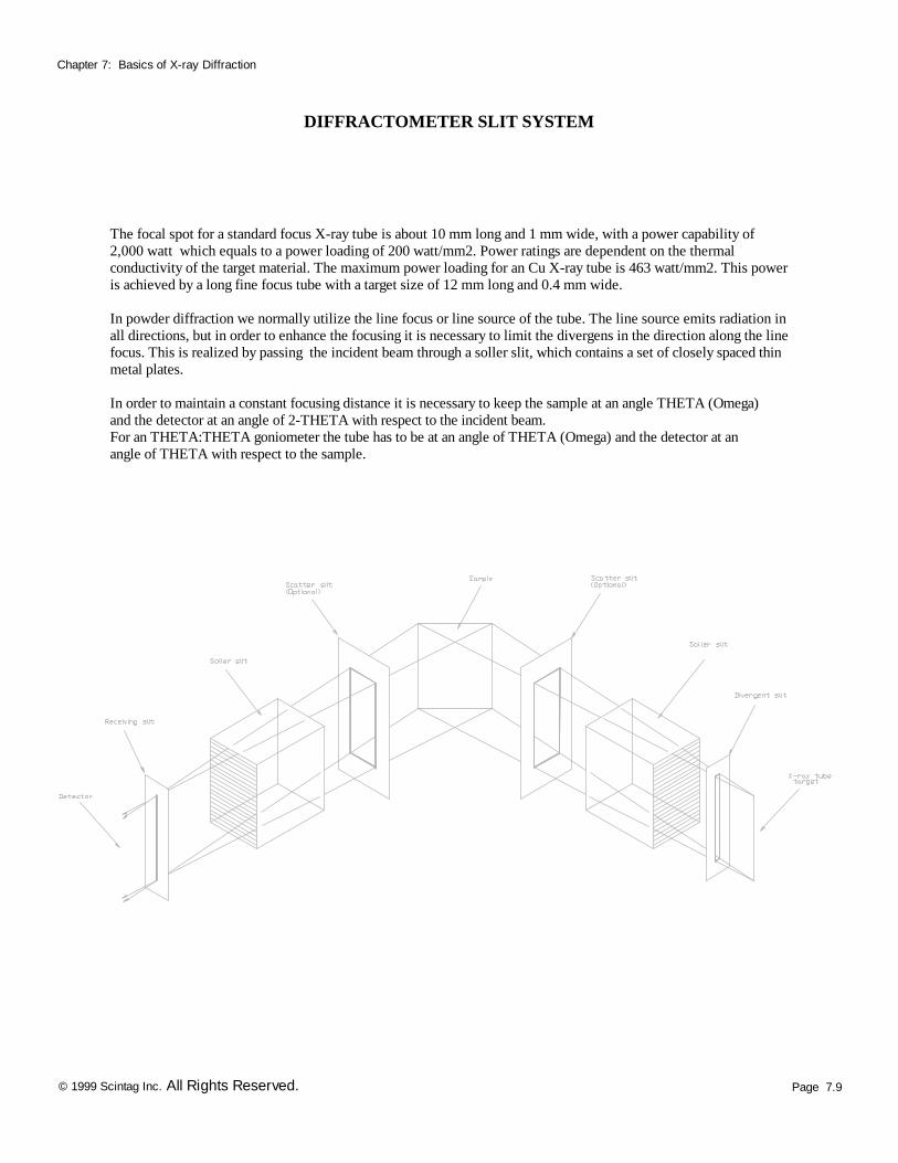
DIFFRACTOMETER SLIT SYSTEM
The focal spot for a standard focus X-ray tube is about 10 mm long and 1 mm wide, with a power capability of 2,000 watt which equals to a power loading of 200 watt/mm2. Power ratings are dependent on the thermal conductivity of the target material. The maximum power loading for an Cu X-ray tube is 463 watt/mm2. This power is achieved by a long fine focus tube with a target size of 12 mm long and 0.4 mm wide. In powder diffraction we normally utilize the line focus or line source of the tube. The line source emits radiation in all directions, but in order to enhance the focusing it is necessary to limit the divergens in the direction along the line focus. This is realized by passing the incident beam through a soller slit, which contains a set of closely spaced thin metal plates. In order to maintain a constant focusing distance it is necessary to keep the sample at an angle THETA (Omega) and the detector at an angle of 2-THETA with respect to the incident beam. For an THETA:THETA goniometer the tube has to be at an angle of THETA (Omega) and the detector at an angle of THETA with respect to the sample.
Page 7.10 © 1999 Scintag Inc. All Rights Reserved.
Chapter 7: Basics of X-ray Diffraction
DIFFRACTION SPECTRA
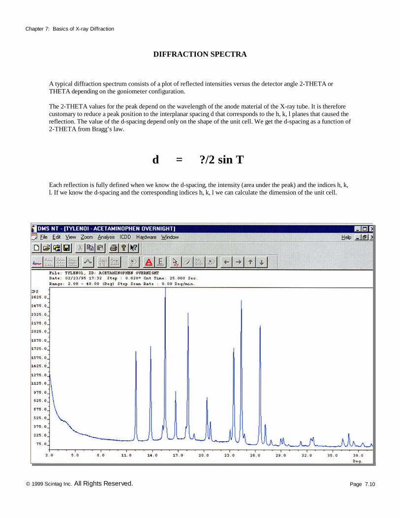
A typical diffraction spectrum consists of a plot of reflected intensities versus the detector angle 2-THETA or THETA depending on the goniometer configuration. The 2-THETA values for the peak depend on the wavelength of the anode material of the X-ray tube. It is therefore customary to reduce a peak position to the interplanar spacing d that corresponds to the h, k, l planes that caused the reflection. The value of the d-spacing depend only on the shape of the unit cell. We get the d-spacing as a function of 2-THETA from Bragg’s law.
d = ?/2 sin T
Each reflection is fully defined when we know the d-spacing, the intensity (area under the peak) and the indices h, k, l. If we know the d-spacing and the corresponding indices h, k, l we can calculate the dimension of the unit cell.

Page 7.11 © 1999 Scintag Inc. All Rights Reserved.
Chapter 7: Basics of X-ray Diffraction
ICDD DATA BASE
International Center Diffraction Data (ICDD) or formerly known as (JCPDS) Joint Committee on Powder Diffraction Standards is the organization that maintains the data base of inorganic and organic spactras. The data base is available from the Diffraction equipment manufacturers or from ICDD direct. Currently the data base is supplied either on magnetic or optical media. Two data base versions are available the PDF I and the PDF II. The PDF I data base contains information on d-spacing, chemical formula, relative intensity, RIR quality information and routing digit. The information is stored in an ASCII format in a file called PDF1.dat. For search/match purposes most diffraction manufactures are reformatting the file in a more efficient binary format. The PDF II data base contains full information on a particular phase including cell parameters. Scintag’s newest search/match and look-up software package is using the PDF II format. Optimized data base formats, index files and high performance PC-computers make PDF II search times extremely efficient. The data base format consists of a set number and a sequence number. The set number is incremented every calendar year and the sequence number starts from 1 for every year. The yearly releases of the data base is available in September of each year.
Page 7.12 © 1999 Scintag Inc. All Rights Reserved.
Chapter 7: Basics of X-ray Diffraction
PREFERRED ORIENTATION
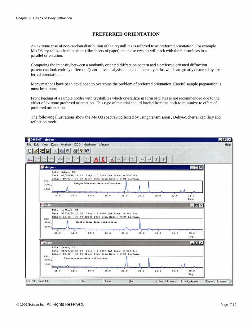
An extreme case of non-random distribution of the crystallites is referred to as preferred orientation. For example Mo O3 crystallizes in thin plates (like sheets of paper) and these crystals will pack with the flat surfaces in a parallel orientation. Comparing the intensity between a randomly oriented diffraction pattern and a preferred oriented diffraction pattern can look entirely different. Quantitative analysis depend on intensity ratios which are greatly distorted by pre-ferred orientation. Many methods have been developed to overcome the problem of preferred orientation. Careful sample preparation is most important. Front loading of a sample holder with crystallites which crystallize in form of plates is not recommended due to the effect of extreme preferred orientation. This type of material should loaded from the back to minimize to effect of preferred orientation. The following illustrations show the Mo O3 spectra's collected by using transmission , Debye-Scherrer capillary and reflection mode.
Page 7.13 © 1999 Scintag Inc. All Rights Reserved.
Chapter 7: Basics of X-ray Diffraction
APPLICATIONS
Identification : The most common use of powder (polycrystalline) diffraction is chemical analysis. This can include phase identification (search/match), investigation of high/low temperature phases, solid solutions and determinations of unit cell parameters of new materials. Polymer crystallinity : A polymer can be considered partly crystalline and partly amorphous. The crystalline domains act as a reinforcing grid, like the iron framework in concrete, and improves the performance over a wide range of temperature. However, too much crystallinity causes brittleness. The crystallinity parts give sharp narrow diffraction peaks and the amorphous component gives a very broad peak (halo). The ratio between these intensities can be used to calculate the amount of crystallinity in the material. Residual stress : Residual stress is the stress that remains in the material after the external force that caused the stress have been removed. Stress is defined as force per unit area. Positive values indicate tensile (expansion) stress, negative values indicate a compressive state. The deformation per unit length is called strain. The residual stress can be introduced by any mechanical, chemical or thermal process. E.g. machining, plating and welding. The principals of stress analysis by the X-ray diffraction is based on measuring angular lattice strain distributions. That is, we choose a reflection at high 2-Theta and measure the change in the d-spacing with different orientations of the sample. Using Hooke’s law the stress can be calculated from the strain distribution. Texture analysis : The determination of the preferred orientation of the crystallites in polycrystalline aggregates is referred to as texture analysis, and the term texture is used as a broad synonym for preferred crystallographic orientation in the polycrystalline material, normally a single phase. The preferred orientation is usually described in terms of polefigures. A polefigure is scanned be measuring the diffraction intensity of a given reflection (2-Theta is constant) at a large number of different angular orientations of the sample. A contour map of the intensity is then plotted as a function of angular orientation of the specimen. The most common representation of the polefigures are sterographic or equal area projections. The intensity of a given reflection (h, k , l) is proportional to the number of h, k , l planes in reflecting condition (Bragg’s law). Hence, the polefigure gives the probability of finding a given crystal-plane-normal as function of the specimen orientation. If the crystallites in the sample have a random orientation the recorded intensity will be uniform. We can use the orientation of the unit cell to describe crystallite directions. The inverse polefigure gives the probability of finding a given specimen direction parallel to crystal (unit cell) directions. By collecting data for several reflections and combining several polefigures we can arrive at the complete orientation distribution function (ODF) of the crystallites within a single polycrystalline phase that makes up the material. Considering a coordinate system defined in relation to the specimen, any orientation of the crystal lattice (unit cell) with respect to the specimen coordinate system may be defined by Euler rotation (three angular values) necessary to rotate the crystal
Page 7.14 © 1999 Scintag Inc. All Rights Reserved.
Chapter 7: Basics of X-ray Diffraction
APPLICATIONS
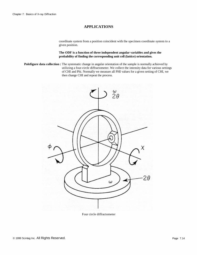
coordinate system from a position coincident with the specimen coordinate system to a given position. The ODF is a function of three independent angular variables and gives the probability of finding the corresponding unit cell (lattice) orientation. Polefigure data collection : The systematic change in angular orientation of the sample is normally achieved by
utilizing a four-circle diffractometer. We collect the intensity data for various settings of CHI and Phi. Normally we measure all PHI values for a given setting of CHI, we then change CHI and repeat the process.
Four circle diffractometer
Page 7.15 © 1999 Scintag Inc. All Rights Reserved.
Chapter 7: Basics of X-ray Diffraction
APPLICATIONS
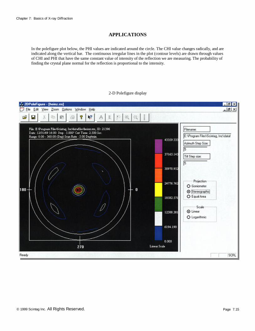
In the polefigure plot below, the PHI values are indicated around the circle. The CHI value changes radically, and are indicated along the vertical bar. The continuous irregular lines in the plot (contour levels) are drawn through values of CHI and PHI that have the same constant value of intensity of the reflection we are measuring. The probability of finding the crystal plane normal for the reflection is proportional to the intensity.
2-D Polefigure display
Page 7.16 © 1999 Scintag Inc. All Rights Reserved.
Chapter 7: Basics of X-ray Diffraction
APPLICATIONS
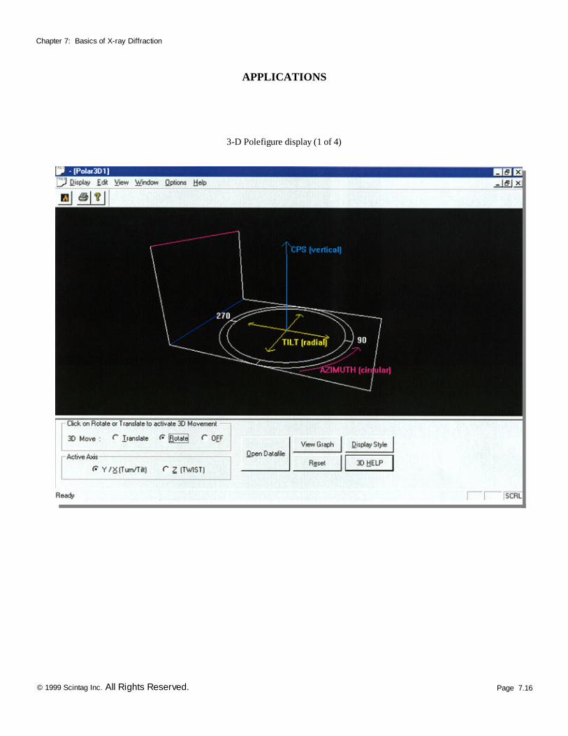
3-D Polefigure display (1 of 4)
Page 7.17 © 1999 Scintag Inc. All Rights Reserved.
Chapter 7: Basics of X-ray Diffraction
APPLICATIONS
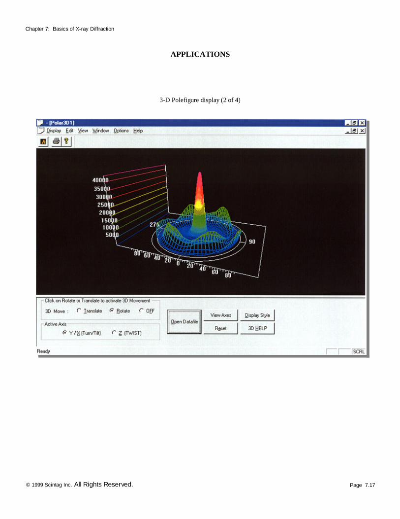
3-D Polefigure display (2 of 4)

Page 7.18 © 1999 Scintag Inc. All Rights Reserved.
Chapter 7: Basics of X-ray Diffraction
APPLICATIONS
3-D Polefigure display (3 of 4)
Page 7.19 © 1999 Scintag Inc. All Rights Reserved.
Chapter 7: Basics of X-ray Diffraction
APPLICATIONS
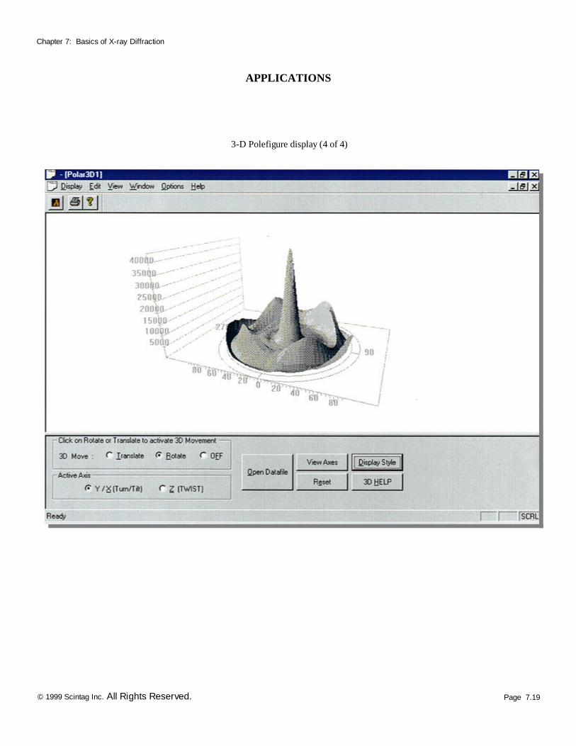
3-D Polefigure display (4 of 4)
Page 7.20 © 1999 Scintag Inc. All Rights Reserved.
Chapter 7: Basics of X-ray Diffraction
TEXTURE ANALYSIS
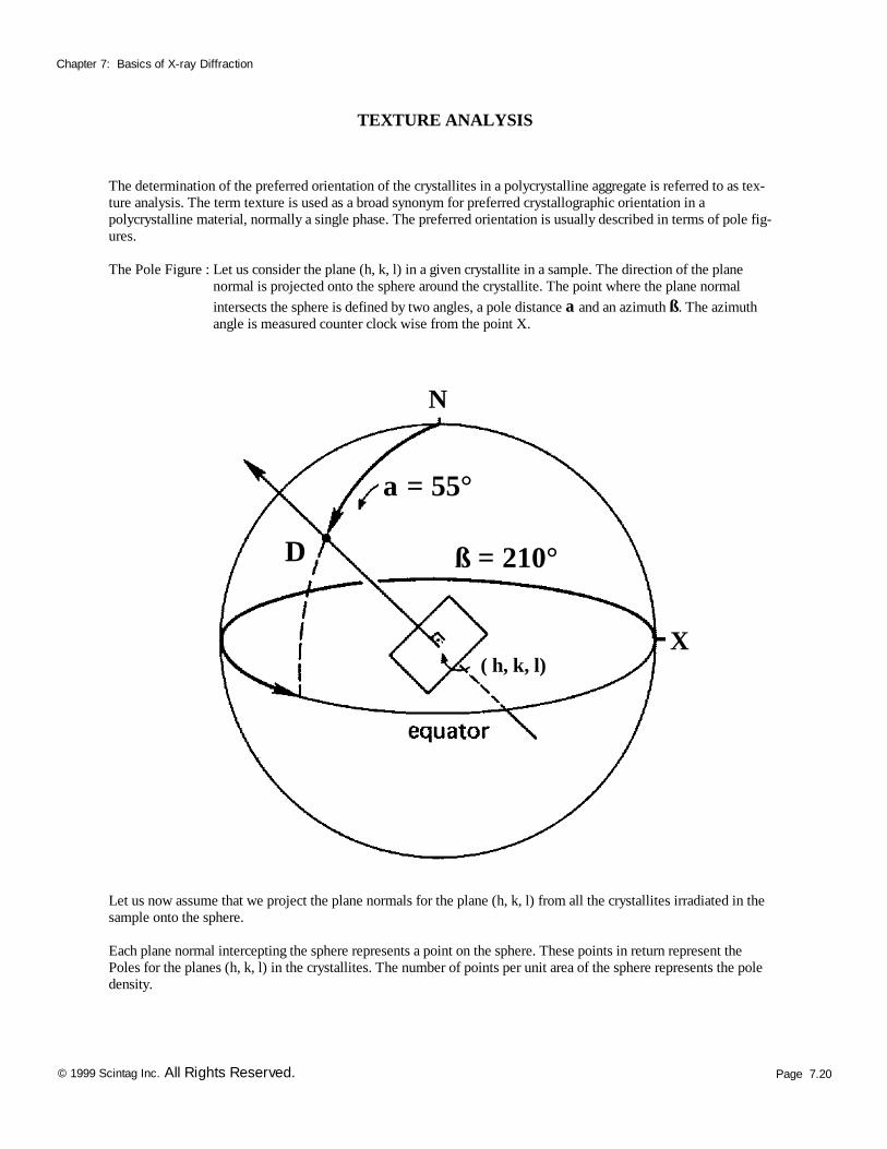
The determination of the preferred orientation of the crystallites in a polycrystalline aggregate is referred to as tex-ture analysis. The term texture is used as a broad synonym for preferred crystallographic orientation in a polycrystalline material, normally a single phase. The preferred orientation is usually described in terms of pole fig-ures. The Pole Figure : Let us consider the plane (h, k, l) in a given crystallite in a sample. The direction of the plane normal is projected onto the sphere around the crystallite. The point where the plane normal intersects the sphere is defined by two angles, a pole distance a and an azimuth ß. The azimuth angle is measured counter clock wise from the point X.
Let us now assume that we project the plane normals for the plane (h, k, l) from all the crystallites irradiated in the sample onto the sphere. Each plane normal intercepting the sphere represents a point on the sphere. These points in return represent the Poles for the planes (h, k, l) in the crystallites. The number of points per unit area of the sphere represents the pole density.
X
N
a = 55°
ß = 210° D
( h, k, l)
Page 7.21 © 1999 Scintag Inc. All Rights Reserved.
Chapter 7: Basics of X-ray Diffraction
TEXTURE ANALYSIS
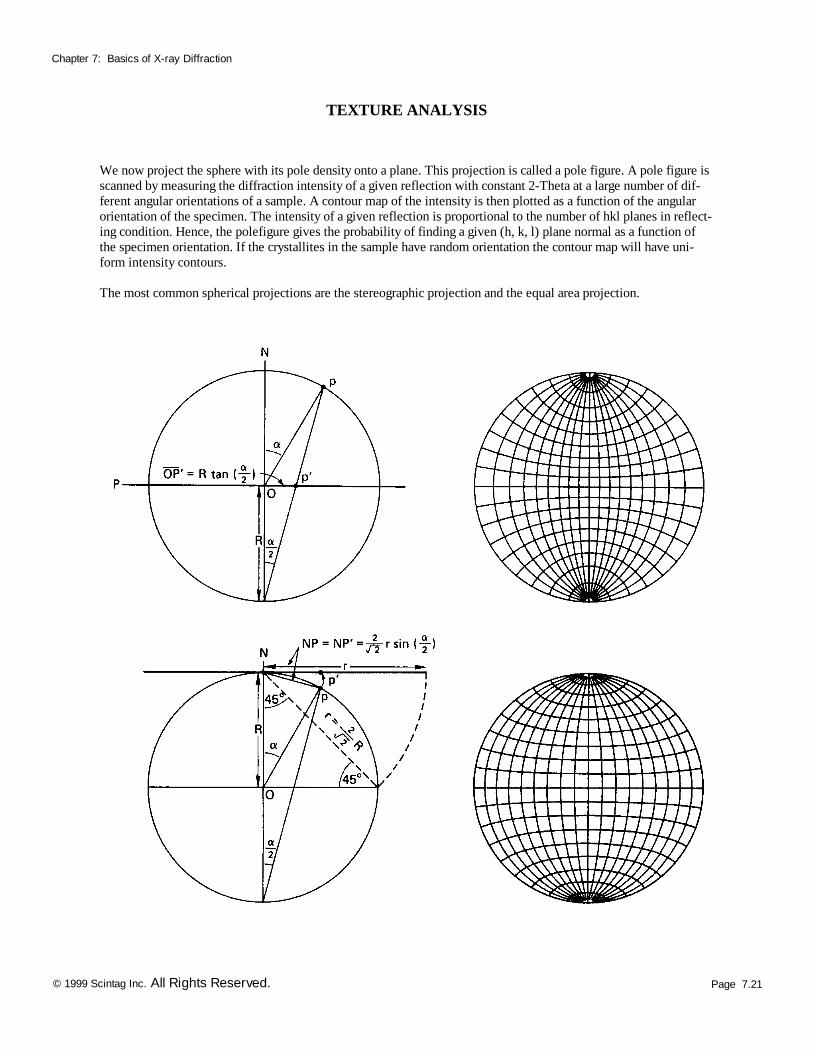
We now project the sphere with its pole density onto a plane. This projection is called a pole figure. A pole figure is scanned by measuring the diffraction intensity of a given reflection with constant 2-Theta at a large number of dif-ferent angular orientations of a sample. A contour map of the intensity is then plotted as a function of the angular orientation of the specimen. The intensity of a given reflection is proportional to the number of hkl planes in reflect-ing condition. Hence, the polefigure gives the probability of finding a given (h, k, l) plane normal as a function of the specimen orientation. If the crystallites in the sample have random orientation the contour map will have uni-form intensity contours. The most common spherical projections are the stereographic projection and the equal area projection.
Page 7.22 © 1999 Scintag Inc. All Rights Reserved.
Chapter 7: Basics of X-ray Diffraction
TEXTURE ANALYSIS
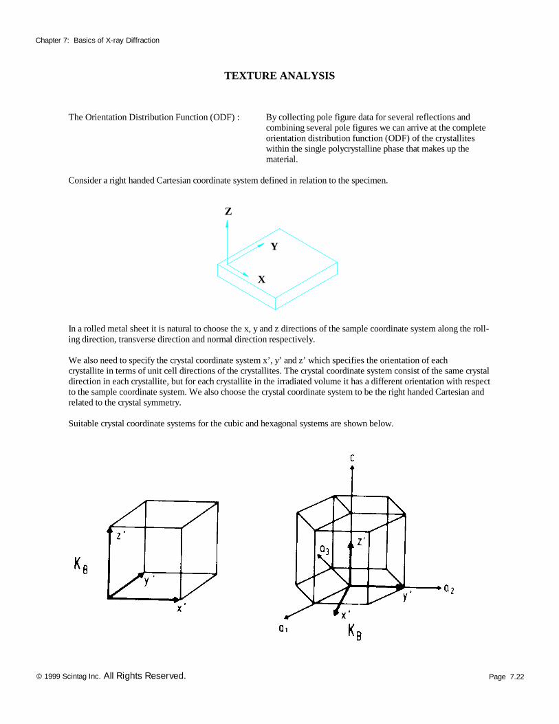
The Orientation Distribution Function (ODF) : By collecting pole figure data for several reflections and combining several pole figures we can arrive at the complete orientation distribution function (ODF) of the crystallites within the single polycrystalline phase that makes up the material. Consider a right handed Cartesian coordinate system defined in relation to the specimen.
In a rolled metal sheet it is natural to choose the x, y and z directions of the sample coordinate system along the roll-ing direction, transverse direction and normal direction respectively. We also need to specify the crystal coordinate system x’, y’ and z’ which specifies the orientation of each crystallite in terms of unit cell directions of the crystallites. The crystal coordinate system consist of the same crystal direction in each crystallite, but for each crystallite in the irradiated volume it has a different orientation with respect to the sample coordinate system. We also choose the crystal coordinate system to be the right handed Cartesian and related to the crystal symmetry. Suitable crystal coordinate systems for the cubic and hexagonal systems are shown below.
Z
X
Y
Page 7.23 © 1999 Scintag Inc. All Rights Reserved.
Chapter 7: Basics of X-ray Diffraction
TEXTURE ANALYSIS
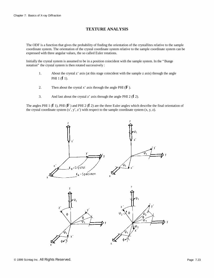
The ODF is a function that gives the probability of finding the orientation of the crystallites relative to the sample coordinate system. The orientation of the crystal coordinate system relative to the sample coordinate system can be expressed with three angular values, the so called Euler rotations. Initially the crystal system is assumed to be in a position coincident with the sample system. In the “Bunge notation” the crystal system is then rotated successively : 1. About the crystal z’ axis (at this stage coincident with the sample z axis) through the angle PHI 1 (f 1). 2. Then about the crystal x’ axis through the angle PHI (F ). 3. And last about the crystal z’ axis through the angle PHI 2 (f 2). The angles PHI 1 (f 1), PHI (F ) and PHI 2 (f 2) are the three Euler angles which describe the final orientation of the crystal coordinate system (x’, y’, z’) with respect to the sample coordinate system (x, y, z).
Page 7.24 © 1999 Scintag Inc. All Rights Reserved.
Chapter 7: Basics of X-ray Diffraction
TEXTURE ANALYSIS
In the “Roe/Matthis notation” the crystal system is initially in a position coincident with the sample system. The crystal system is then rotated successively : 1. About the crystal z’ axis (at this stage coincident with the sample z axis) through the angle PSI (? ). 2. Then about the crystal x’ axis through the angle Theta (?). 3. And last about the crystal z’ axis through the angle PHI (F ). The relations between the two notations ( Bunge & Roe/Matthis) are given by :
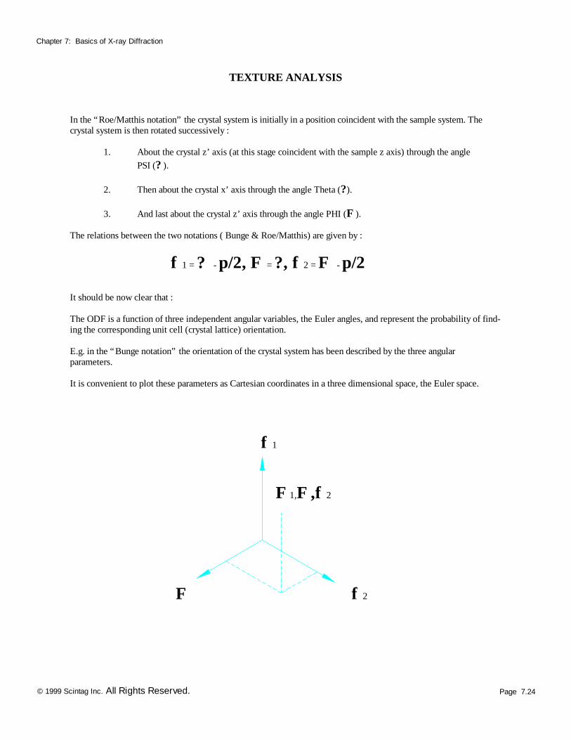
f 1 = ? - p/2, F = ?, f 2 = F - p/2 It should be now clear that : The ODF is a function of three independent angular variables, the Euler angles, and represent the probability of find-ing the corresponding unit cell (crystal lattice) orientation. E.g. in the “Bunge notation” the orientation of the crystal system has been described by the three angular parameters. It is convenient to plot these parameters as Cartesian coordinates in a three dimensional space, the Euler space.
F
f 1
f 2
F 1,F ,f 2
Page 7.25 © 1999 Scintag Inc. All Rights Reserved.
Chapter 7: Basics of X-ray Diffraction
End of Basics of X-ray Diffraction