xpr series - car audio | multimedia | marine audio / owner's manual mobile power amplifiers xpr...
TRANSCRIPT

INSTALLATION / OWNER'S MANUALMobile Power Amplifiers
XPR SERIES
XPR522
XPR540

2
PreparationPlease read entire manual before installation. Due to the technical nature of amplifiers, it is highly recommended that your DUAL amplifier is installed by a professional installer or an authorized dealer.
Before You Start•Disconnectnegativebatteryterminal.(consultaqualifiedtechnicianforinstructions)•Avoidinstallingtheamplifierwhereitwouldbesubjecttohightemperatures,suchasfromdirectsunlight,orwhereitwouldbesubjecttodust,dirtorexcessivevibration.•Useextremecautionwhendrillingholestoavoiddamagingfuellinesorexistingvehiclewiring.•Allamplifierinstallationsrequirepower,signalandspeakerwires(notincluded).•Anamplifierinstallationkit(soldseparately)ishighlyrecommendedtofacilitatethe
installation. Consult your dealer for recommendations.
Mounting Location•Chooseamountinglocationfortheamplifier.Suggestedlocationsincludeunderaseatorinthetrunk.•Theamplifiercanbemountedhorizontal(recommended)orvertical.Foroptimumperformance,makesuretoprovideatleast1"ofspacetoaroundallsides.Donotmounttheamplifierundercarpetsorwhereairflowisrestricted.•Donotinstalltheamplifierwhereitmaybeexposedtomoisture.•Theoptimummountinglocationvariesbetweenvehicles.Remembertotestall
amplifier functions before completing the final mounting procedure.
TYPICAL MOUNTING METHOD
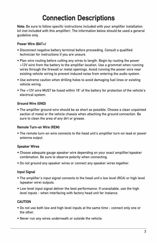
Note: Besuretofollowspecificinstructionsincludedwithyouramplifierinstallationkit(notincludedwiththisamplifier).Theinformationbelowshouldbeusedageneralguideline only.
Power Wire (BAT+)
•Disconnectnegativebatteryterminalbeforeproceeding.Consultaqualifiedtechnician for instructions if you are unsure.
•Planwireroutingbeforecuttinganywirestolength.Beginbyroutingthepower+12Vwirefromthebatterytotheamplifierlocation.Useagrommetwhenrunningwiresthroughthefirewallormetalopenings.Avoidrunningthepowerwirenearexistingvehiclewiringtopreventinducednoisefromenteringtheaudiosystem.
•Useextremecautionwhendrillingholestoavoiddamagingfuellinesorexistingvehiclewiring.
•The+12VwireMUSTbefusedwithin18"ofthebatteryforprotectionofthevehicle’selectrical system.
Ground Wire (GND)
•Theamplifiergroundwireshouldbeasshortaspossible.Chooseacleanunpaintedsectionofmetalorthevehiclechassiswhenattachingthegroundconnection.Besure to clean the area of any dirt or grease.
Remote Turn-on Wire (REM)
•Theremoteturn-onwireconnectstotheheadunit'samplifierturn-onleadorpowerantenna output.
Speaker Wires
•Chooseadequategaugespeakerwiredependingonyourexactamplifier/speakercombination.Besuretoobservepolaritywhenconnecting.
•Donotgroundanyspeakerwiresorconnectanyspeakerwirestogether.
Input Signal
•Theamplifier'sinputsignalconnectstotheheadunit'slowlevel(RCA)orhighlevel(speakerwire)outputs.
•Lowlevelinputsignaldeliverthebestperformance.Ifunavailable,usethehighlevelinputs-wheninterfacingwithfactoryheadunitforinstance.
CAUTION
•Donotusebothlowandhighlevelinputsatthesametime-connectonlyoneor the other.
•Neverrunanywiresunderneathoroutsidethevehicle.
3
Connection Descriptions

4
Audio Inputs and Controls
XPR522
RCALineInputs
SpeakerInputs
Gain
CrossoverMode
1
2
3
CrossoverFrequencyControl
Bass Boost
InputMode
2 53 64
1 27 3 4 5 6
4
5
6
7
1
XPR522
XPR540
XPR522
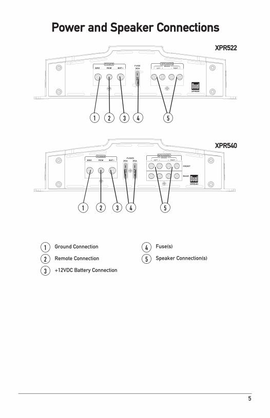
Power and Speaker Connections
Ground Connection
RemoteConnection
+12VDCBatteryConnection
1
2
3
Fuse(s)
SpeakerConnection(s)
4
5
5
XPR522
1 32 54
1 32 54
XPR522
XPR540

6
Fuse RatingWhenreplacingfuses,makesurenewfuseis the correct type and amperage. Using an incorrect fuse could damage the amplifier.
XPR52230ampATOx1XPR54025ampATOx2
Main Power ConnectionsConnect+12V,GNDandREMwiresaccordingly.AsuitablefuseMUSTbeinstalledonthe+12Vleadwithin18"ofthebatteryforprotectionofthevehicle’selectricalsystem.
Typical Wire Routing
Power/Ground Wire SizeForoptimumperformance,useonlythewiresizelistedbeloworlarger.Makesuretousethesamesizepowerandgroundwire. XPR52210awgXPR5408awg

7
Amplifier ConnectionsSpeaker ConnectionsConnectspeakerwiresobservingpolarity. TheminimumimpedanceloadfortheXPR522orXPR540is 2 ohms stereo and 4 ohms bridged.Useofloadslowerthanthese is not recommended and maycauseamplifierdamage.TheXPR522andXPR540canbewiredforstereo,bridgedorstereo/bridged simultaneous operation.
Input Signal Connections
Low Level Input (RCA)Lowlevel(RCA)inputsignalispreferredforbestperformance.Typicaltrunk-mountamplifierinstallationsrequirea17-20footRCAcable.Mosttrucksandunder-seatapplicationsrequirea6-9footRCAcable.UsingtwistedpairconstructionRCAcableswillminimize noise.
High Level Input (Speaker Wire)High level inputs should only be used when RCA outputs are not available from the head unit. Connecttheheadunitspeakeroutputstothehighlevelinputconnectorasshownbelow.Theblackwire(signalreferenceground)mayormaynotrequireaconnectiontochassisground-dependingonyour particular installation.
Subwoofer (mono)
Typical Bridged Wiring(4 ohms minimum)
2 Speakers (stereo)
Typical Stereo Wiring(2 ohms minimum)
HI-LEVEL INPUT CONNECTION
Grey = Right (+)Grey/Black = Right (-)Black = GroundWhite/Black = Left (-)White = Left (+)
CAUTION Donotusebothlowandhighlevelinputsatthesametime-connectonlyoneortheother.
XPR522speakerconnectionsshown

8
Configuration/SetupTheinputlevelcontrol(gain)isusedtoobtainthebestpossiblematchbetweentheheadunitaudiooutputandtheamplifier input.
• Beginbyturningtheinputlevelcontrolfullycounterclockwise.
•Next,turnuptheheadunitvolumecontrolaround3/4ofthewayup.
• Adjusttheinputlevelcontrolclockwiseuntilaudibledistortionisheard,thenslightlycounterclockwisetoprovidethebestmatch.
• Repeatforallinputlevelcontrols. Select2 CHmodeiftheheadunitonlyhas1pairofRCAoutputs.PlugtheRCA’sfromtheheadunitintoeitherthefrontorrearchannel.All4amplifierinputswillreceiveasignal.
Note:Thereisnofaderfunctionwhenusing2 CH mode.
Select4 CHmodeiftheheadunithas2pairsofRCAoutputs.PlugtheRCA’sfromtheheadunitintoeitherthefrontorrear channel.
Thecrossoverisusedtofilteroutfrequenciesaboveorbelowacertainpoint.ChooseLPFwhenusingtheamplifierwithsubwoofers,HPFwhenusingwithmidrange/tweetercombinations and OFFwhenusingwithcoaxial-typespeakers.
Note: Choose OFFwhenusingtheamplifierinstereo/bridgedsimultaneousmode.Inthismode,passivecrossoversarerequired.Failuretousethecorrectpassivecomponentsmaydamagetheamplifierand/orspeakers.Consultaqualifiedprofessionalforrecommendations.
Thiscontrolallowspreciseadjustmentofthecrossoverfrequency.
Thiscontrolprovidesadditionalboost@45Hzwhenusedwithsubwoofers.Adjustthiscontrolwithcaution-asimproperusecandamagespeakers!
TheLEDindicatorilluminatesblueduringnormaloperation(POWER)andredwhentheamplifierdetectsafault(PROTECT).
Input level Control
Input Mode Switch(XPR540)
Crossover Mode
Crossover Frequency Control
Bass Boost
LED Indicator

9
Limited One-Year Warranty
Thiswarrantygivesyouspecificlegalrights.Youmayalsohaveotherrightswhichvaryfromstatetostate.
DualElectronicsCorp.warrantsthisproduct to the original purchaser to be free fromdefectsinmaterialandworkmanshipfor a period of one year from the date of the original purchase.
DualElectronicsCorp.agrees,atouroption,duringthewarrantyperiod,to repair any defect in material or workmanshiportofurnishanequalnew,renewedorcomparableproduct(whicheverisdeemednecessary)inexchangewithoutcharges,subjecttoverificationofthedefectormalfunctionandproofofthedateofpurchase.Subsequentreplacementproductsarewarrantedforthebalanceoftheoriginalwarrantyperiod.
Who is covered?Thiswarrantyisextendedto the original retail purchaser for products purchased from an authorized Dual dealer andusedintheU.S.A.
What is covered?Thiswarrantycoversalldefectsinmaterialandworkmanshipinthisproduct.Thefollowingarenotcovered:software,installation/removalcosts,damage resulting from accident, misuse, abuse, neglect, product modification, improper installation, incorrect line voltage,unauthorizedrepairorfailuretofollowinstructionssuppliedwiththeproduct, or damage occurring during returnshipmentoftheproduct.Specificlicense conditions and copyright notices for thesoftwarecanbefoundviawww.dualav.com.
What to do? 1.Beforeyoucallforservice,checkthetroubleshootingguideinyourowner’smanual.Aslightadjustmentofanycustomcontrolsmaysaveyouaservicecall.
2.Ifyourequireserviceduringthewarrantyperiod,youmustcarefullypacktheproduct(preferablyintheoriginalpackage)andshipitbyprepaidtransportationwithacopyoftheoriginalreceipt from the retailer to an authorizedservicecenter.
3. Please describe your problem in writingandincludeyourname,areturnUPSshippingaddress(P.O.Boxnotacceptable),andadaytimephonenumberwithyourshipment.
4.Formoreinformationandforthelocation of the nearest authorized servicecenterpleasecontactusbyoneofthefollowingmethods:
•Callustoll-freeat1-866-382-5476•[email protected]
ExclusionofCertainDamages:Thiswarrantyisexclusiveandinlieuofanyandallotherwarranties,expressedorimplied,includingwithoutlimitationtheimpliedwarrantiesofmerchantabilityandfitness for a particular purpose and any obligation, liability, right, claim or remedy incontractortort,whetherornotarisingfromthecompany’snegligence,actualorimputed.Nopersonorrepresentativeis authorized to assume for the company anyotherliabilityinconnectionwiththesaleofthisproduct.Innoeventshallthecompany be liable for indirect, incidental or consequentialdamages.
10
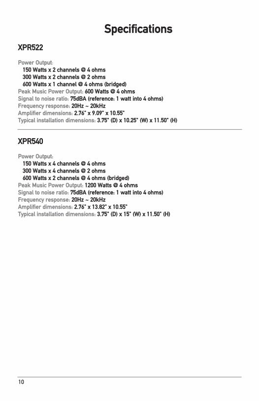
Specifications XPR522
Power Output: 150 Watts x 2 channels @ 4 ohms 300 Watts x 2 channels @ 2 ohms 600 Watts x 1 channel @ 4 ohms (bridged) Peak Music Power Output: 600 Watts @ 4 ohmsSignal to noise ratio: 75dBA (reference: 1 watt into 4 ohms)Frequency response: 20Hz ~ 20kHz Amplifier dimensions: 2.76" x 9.09" x 10.55"Typical installation dimensions: 3.75" (D) x 10.25" (W) x 11.50" (H)
XPR540
Power Output: 150 Watts x 4 channels @ 4 ohms 300 Watts x 4 channels @ 2 ohms 600 Watts x 2 channels @ 4 ohms (bridged) Peak Music Power Output: 1200 Watts @ 4 ohmsSignal to noise ratio: 75dBA (reference: 1 watt into 4 ohms)Frequency response: 20Hz ~ 20kHz Amplifier dimensions: 2.76" x 13.82" x 10.55"Typical installation dimensions: 3.75" (D) x 15" (W) x 11.50" (H)
11
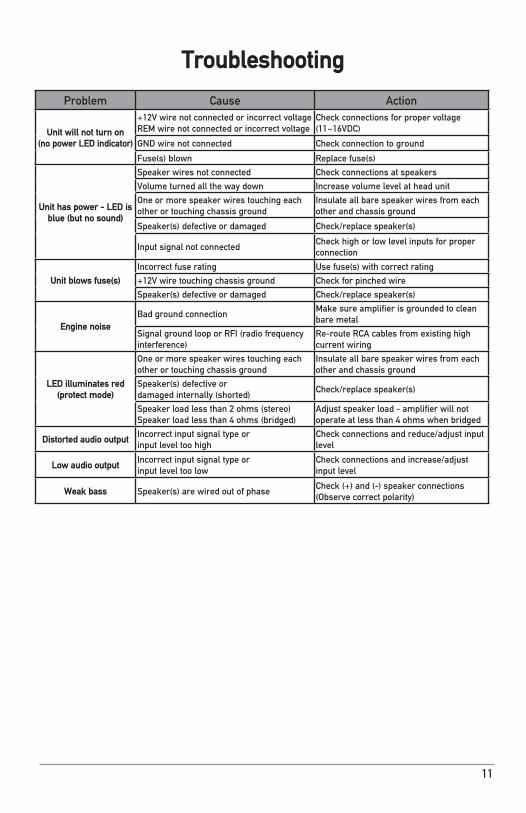
Troubleshooting
Problem Cause Action
Unit will not turn on(no power LED indicator)
+12VwirenotconnectedorincorrectvoltageREMwirenotconnectedorincorrectvoltage
Checkconnectionsforpropervoltage(11~16VDC)
GNDwirenotconnected Checkconnectiontoground
Fuse(s)blown Replacefuse(s)
Unit has power - LED is blue (but no sound)
Speakerwiresnotconnected Checkconnectionsatspeakers
Volumeturnedallthewaydown Increasevolumelevelatheadunit
Oneormorespeakerwirestouchingeachother or touching chassis ground
Insulateallbarespeakerwiresfromeachother and chassis ground
Speaker(s)defectiveordamaged Check/replacespeaker(s)
InputsignalnotconnectedCheckhighorlowlevelinputsforproperconnection
Unit blows fuse(s)
Incorrectfuserating Usefuse(s)withcorrectrating
+12Vwiretouchingchassisground Checkforpinchedwire
Speaker(s)defectiveordamaged Check/replacespeaker(s)
Engine noiseBad ground connection
Makesureamplifierisgroundedtocleanbare metal
SignalgroundlooporRFI(radiofrequencyinterference)
Re-routeRCAcablesfromexistinghighcurrentwiring
LED illuminates red(protect mode)
Oneormorespeakerwirestouchingeachother or touching chassis ground
Insulateallbarespeakerwiresfromeachother and chassis ground
Speaker(s)defectiveordamagedinternally(shorted)
Check/replacespeaker(s)
Speakerloadlessthan2ohms(stereo)Speakerloadlessthan4ohms(bridged)
Adjustspeakerload-amplifierwillnotoperateatlessthan4ohmswhenbridged
Distorted audio outputIncorrectinputsignaltypeorinputleveltoohigh
Checkconnectionsandreduce/adjustinputlevel
Low audio outputIncorrectinputsignaltypeorinputleveltoolow
Checkconnectionsandincrease/adjustinputlevel
Weak bass Speaker(s)arewiredoutofphaseCheck(+)and(-)speakerconnections(Observecorrectpolarity)

DualElectronicsCorp.TollFree:1-866-382-5476
www.dualav.com©2013DualElectronicsCorp.
NSA0513-V01