workpackage 2 fire development and mitigation measures d251 engineering guidance for water based...
TRANSCRIPT

official deliverable © version September 2008
Workpackage 2 Fire development and mitigation measuresD251
Engineering Guidance for Water Based Fire Fighting Systems for the Protection of Tunnels and Sub Surface Facilities
AuthorsToby McCoryARUP FireDirk SprakelFogtecErik ChristensenSemco
EU FP5 Contract G1RD-CT-2002-766

UPTUN UPTUN is an acronym for the title of a research project carried out in the scope of the 5th Framework Programme of the European Commission, under contract G1RD-CT-2002-766. UPTUN stands for: “Cost effective sustainable and innovative UPgrading Methods for Fire Safety in existing TUNnels”. In the project, officially started September 1st 2002 and officially closed August 31st 2006, 41 partners out of 19 EU member states participated and closely worked together in a joint effort to overcome fire safety issues emerging from the tragic Alpine tunnel accidents in the years 1990-2000. UPTUN’s objectives were: 1) Development of innovative methodologies and technologies where appropriate and, where relevant,
comparison to and assessment of existing methodologies and technologies for tunnel application. New technologies have been developed: water mist, water curtains, smoke compartmentation, CCTV detection techniques, training tools and programs, repair mortars and software assessment tools, including local and regional cost effect models.
2) Development, demonstration and promotion of procedures for rational safety level evaluation, including decision support models and knowledge transfer. Safety level assessment criteria were drawn up and integrated in manual and automatic upgrade procedures/models. Knowledge was transferred through dissemination on various levels: papers and presentations, international symposia (Prague, Lausanne), dedicated workshops throughout Europe and beyond (Australia, China, USA) and the establishment of a manual for good practice and an UPTUN summer course.
The desired spin-off was the restoration of faith in tunnels as safe components of the transportation systems, the levelling out of trade barriers imposed by supposedly unsafe tunnels, and an increased awareness of stakeholders of the necessity to develop initiatives to link all relevant research. All official UPTUN deliverables, and their latest versions, can be obtained through www.uptun.net. Disclaimer The partners in the UPTUN project (hereinafter referred to as UPTUN), declare that any content in the official UPTUN deliverables, including the information, names, images, pictures, logos and icons regarding or relating to UPTUN is provided “AS IS” and on an “IS AVAILABLE” basis without any representations or any kind of warranty made (whether express or implied by law) to the extent permitted by law, including the implied warranties of satisfactory quality, fitness for a particular purpose, non-infringement, compatibility, security and accuracy. Under no circumstances will UPTUN be liable for any of the following losses or damage (whether such losses were foreseen, foreseeable, known or otherwise): (a) loss of data; (b) loss of revenue or anticipated profits; (c) loss of business; (d) loss of opportunity; (e) loss of goodwill or injury to reputation; (f) losses suffered by third parties; or (g) any indirect, consequential, special or exemplary damages arising from the use of UPTUN content regardless of the form of action. UPTUN does not warrant that functions contained in UPTUN content will be uninterrupted or error free, that defects will be corrected, or that the UPTUN website or the server that makes it available are free of viruses or bugs. www.uptun.net September 2008 ©

Engineering Guidance for Water Based Fire Fighting Systems
for the Protection of Tunnels and Sub Surface Facilities
Work Package 2.5 of the Research Project UPTUN of the European Commission
(Revision 05) R251
August 2006

1 Introduction.......................................................................................................... 4
2 Related standards and guidelines ....................................................................... 5
3 Background ......................................................................................................... 6
4 Water Based Fire Fighting Systems (WFS)........................................................ 7
4.1 Cooling. ........................................................................................................ 7
4.2 Suffocation of the Fire. ................................................................................. 8
4.3 Separation effect .......................................................................................... 8
4.4 Shielding effect............................................................................................. 9
4.5 Protection of the Tunnel structure ................................................................ 9
4.6 Objections against WFS............................................................................... 9
5 Definitions.......................................................................................................... 10
5.1 Area protection systems............................................................................. 10
5.2 Authority having jurisdiction........................................................................ 10
5.3 Design Parameters:.................................................................................... 10
5.4 Downstream ............................................................................................... 10
5.5 FMEA ......................................................................................................... 10
5.6 Fire control ................................................................................................. 10
5.7 Fire suppression......................................................................................... 10
5.8 Layout parameters ..................................................................................... 10
5.9 Main supply line.......................................................................................... 10
5.10 Maintenance............................................................................................... 10
5.11 Maximum and Minmum Pressure............................................................... 11
5.12 Maximum Operating Pump Pressure ......................................................... 11
5.13 MTTF.......................................................................................................... 11
5.14 Protection Area........................................................................................... 11
5.15 Section ....................................................................................................... 11
5.16 Section valve.............................................................................................. 11
5.17 Shall ........................................................................................................... 11
5.18 Should ........................................................................................................ 11
5.19 Upstream.................................................................................................... 11
5.20 Water supply .............................................................................................. 11
6 Field of Application ............................................................................................ 12
7 Fire Suppression versus Fire Extinguishing ...................................................... 13
8 Exclusions / Warning......................................................................................... 13
9 General arrangement of the WFS...................................................................... 13
10 Interaction with other Systems....................................................................... 14
10.1 Fire detection system ................................................................................. 14
10.2 CCTV / Thermal Cameras.......................................................................... 14
10.3 Ventilation system ...................................................................................... 15
10.4 Structural Fire Protection............................................................................ 15
10.5 Drainage System........................................................................................ 15
11 System Design............................................................................................... 16
11.1 System Layout............................................................................................ 16
11.1.1 Layout parameters .............................................................................. 17
11.1.2 System Classification .......................................................................... 17
11.1.2.1 Droplet Size Classification ........................................................... 17
11.1.2.2 Working Pressure Classification .................................................. 17
11.1.2.3 Fire Testing .................................................................................. 18
11.1.2.3.1 Geometry of the test tunnel..................................................... 18
11.1.2.3.2 Ventilation condition................................................................ 18

11.1.2.3.3 Fire scenarios ......................................................................... 18
11.1.2.3.4 Activation ................................................................................ 19
11.1.2.3.5 WFS........................................................................................ 20
11.1.2.3.6 Third Party supervision ........................................................... 20
11.1.2.4 Computer Simulations.................................................................. 21
11.1.2.5 Extrapolation and Interpolation .................................................... 21
11.2 Detailed Design.......................................................................................... 22
11.2.1 Water Reservoirs ................................................................................ 22
11.2.2 Filtration .............................................................................................. 23
11.2.2.1 Pre-Filtering ................................................................................. 23
11.2.2.2 Main Filter .................................................................................... 23
11.2.2.3 Nozzle Filters ............................................................................... 23
11.2.3 Quality of material in contact with water .............................................. 23
11.2.4 Booster Pump ..................................................................................... 24
11.2.5 Pump Units.......................................................................................... 24
11.2.5.1 Pump Capacity............................................................................. 24
11.2.5.2 Pump Types................................................................................. 25
11.2.5.3 Multiple Pumps and Redundancy ................................................ 25
11.2.5.4 Safety Valves ............................................................................... 26
11.2.5.5 Type of motor / Power Supply...................................................... 26
11.2.5.6 Pump Room ................................................................................. 27
11.2.6 Jockey Pump....................................................................................... 27
11.2.7 Pipe work ............................................................................................ 27
11.2.7.1 Hydraulic Calculation ................................................................... 27
11.2.7.2 Material ........................................................................................ 27
11.2.7.3 Connectors................................................................................... 28
11.2.7.4 Dimensioning ............................................................................... 28
11.2.7.5 Protection against Freezing ......................................................... 28
11.2.7.6 Pipe supports ............................................................................... 28
11.2.7.7 Thermal expansion ...................................................................... 28
11.2.8 Flushing and Pressure Testing............................................................ 29
11.2.9 Section Valves .................................................................................... 29
11.2.10 Nozzles............................................................................................ 29
11.2.11 Activation......................................................................................... 30
11.2.12 Control Systems .............................................................................. 31
11.2.13 Detection Systems........................................................................... 32
11.2.14 Pump Control System...................................................................... 33
11.2.15 Valve Control ................................................................................... 33
11.3 Additives..................................................................................................... 34
11.4 System Documentation .............................................................................. 35
12 Maintenance .................................................................................................. 36
13 Spare Parts.................................................................................................... 37
14 Training.......................................................................................................... 37
15 Requirements on Contractors ........................................................................ 37
16 DISCLAIMER................................................................................................. 37

www.uptun.net
Engineering Guidance for Water Based WP 2.5
Fire Fighting Systems in Tunnels Page 4 of 37
1 Introduction
This guideline provides information on the design, installation and maintenance of Water Based Fixed Fire Fighting Systems (WFS) for the protection of tunnels. In order to design a WFS for the use in such Subsurface Facilities or to facilitate the preparation of a project and/or a tender invitation, below are presented a summary of layout basics, essential minimum requirements for the system and preconditions to be complied with by designers, installers and tunnel operators. These bases are no substitute for a detailed planning but they are to be understood as the fundamentals for such detailed design. They allow minimum requirements to be defined to ensure that fixed fire fighting systems for the use in tunnels are designed, put in place and maintained professionally to provide the required level of protection and reliability.

www.uptun.net
Engineering Guidance for Water Based WP 2.5
Fire Fighting Systems in Tunnels Page 5 of 37
2 Related standards and guidelines
Relevant guidelines shall be considered where appropriate. These guidelines and standards include but are not limited to: 2004/54/EC, Minimum safety requirements for tunnels in the Trans-European road network EN 54-4, Fire detection and fire alarm systems EN 12094-1, Components for gas extinguishing systems EN 12259-1, Components for sprinkler and water spray systems EN 12845, Automatic sprinkler systems – Design, installation and maintenance. prEN 14816, Water spray systems – Design and installation. prEN/TS 14972, Water Mist Systems, Design and Installation EN ISO 14847, Rotary positive displacement pumps – Technical requirements (ISO 14847:1999). EN 15004-1 Gas Extinguishing Systems 97/23/EC, Pressure Equipment Directive NFPA 13, Installation of Sprinkler Systems NFAP 20, Standard for the Installation of Stationary Fire Pumps for Fire Protection NFPA 502, Standard for Road Tunnels, Bridges, and Other Limited Access Highways NFPA 750, Standard on Water Mist Fire Protection Systems Richtlinie für die Ausstatung und den Betrieb von Strassentunneln (RABT), der Forschungsgesellschaft für Strassen- und Verkehrswesen, Issue 2003

www.uptun.net
Engineering Guidance for Water Based WP 2.5
Fire Fighting Systems in Tunnels Page 6 of 37
Typical Tunnel Cross Section (Drawing Courtesy of TST, Spain)
3 Background
This guideline has been prepared as the outcome of one of the tasks of the European Research Project UPTUN1 on behalf of the European Commission. Traditionally tunnels and other subsurface facilities have not been protected with fixed fire fighting systems. Only Japan and Australia are known to have a history of such protection concepts. However, after a number of substantial fires in European tunnels which caused numerous casualties , the subject of fixed fire suppression systems in tunnels has been discussed intensely. While for most fire risks it is common practice to attempt to mitigate a fire and it's effects (through active or passive measures), for many decades the philosophy for tunnel design typically allowed fires to freely develop. The focus of fire safety in tunnels typically considered the time available for occupant evacuation before a fire has grown too big, or conditions in the tunnel have become too severe, and, the protection to the structure of the subsurface facility. Following various research projects (see www.uptun.net, www.etnfit.net, www.solit.info (ongoing), Runehamar tests (www.sp.se) or www.tunnelfire.com)) it is now understood
11 This guideline has been prepared as part of Work Package 2 of the UPTUN Program under the coordination of ArupFire. See for details: www.uptun.net

www.uptun.net
Engineering Guidance for Water Based WP 2.5
Fire Fighting Systems in Tunnels Page 7 of 37
that fires in tunnels may reach heat release rates of 100 or even 200 MW within a very short time and that the effects of such fires can be disastrous, both in terms of loss of life and loss of property, which can have a major economic impact for several years. Consequently, the common approach of fighting, or mitigating, a fire and its effects, applied in other areas of the fire protection industry, have become an accepted practice in tunnels. Meanwhile full size fire tests, some forming part of the aforementioned research projects, in a number of special test tunnels as well as in real tunnels have shown that WFS can be effective mitigation means in a tunnel environment.
4 Water Based Fire Fighting Systems (WFS)
WFS use water in the form of droplets. Depending on the system type the average droplet size may vary from very small droplets for so called High Pressure Water Mist Systems up to relatively large droplets as created by so called Deluge or Sprinkler Systems. The following main fire fighting effects are used by all WFS2. Depending on the droplet sizes used the efficiency in making use of these potential effects varies.
4.1 Cooling. As a consequence of the extinguishing water being split up into droplets, a reaction surface is created via which the heat from the fire is absorbed. It takes 335 kJ of energy to heat 1 litre of water from 20 to 100 C, and an additional 2257 kJ to transform the water to steam. Thus, water is the extinguishing medium with the highest known heat absorption capacity. The larger the reaction surface is, which is dependent on the droplet size distribution, the higher the potential cooling effect is. The smaller the mean droplet size, the more efficient the cooling effect. This cooling effect refers to the cooling of the air and gases around a fire and not to the cooling of the fire load itself. For the latter effect the surface size of the fire load is the defining factor for the cooling. Therefore, more efficient cooling of the tunnel environment will occur while the water droplets are in the air. Subsequently, small droplets, which will tend to fall slower than larger droplets, will have a more efficient cooling effect on the tunnel environment
2 See for details: Water Mist Fire Extinguishing Systems, in IFP, issue 1/2000

www.uptun.net
Engineering Guidance for Water Based WP 2.5
Fire Fighting Systems in Tunnels Page 8 of 37
Cooling Effect during an UPTUN Fire Test
3
4.2 Suffocation of the Fire. During the evaporation of the water its volume will be increased by 1640 times, which leads to a reduction of the Oxygen content in the air at the source of the fire. Thus the fire will be suffocated or at least it will be suppressed due to the lack of sufficient oxygen needed for the combustion process. NOTE: The reduction of Oxygen content, due to the formation of steam, only takes place at locations where very high temperatures occur. Therefore, a reduction of Oxygen content will tend to occur close to the fire rather than where occupants are escaping.
4.3 Separation effect Water droplets that are located between the flame and fuel surface reduce the radiant heat received by the fuel surface, effectively reflecting the heat.. Subsequently the burning rate reduces, and the radiant heat, received by any potential fire loads in the surrounding tunnel area, will also reduce, decreasing the likelihood of flame spread, due to this "separation" effect.. The "reflection" effect is dependent on the sufficient generation of very small water droplets - the capacity of the effect increases with decreasing water droplet size.
3 Curves show temperatures at various locations during a full scale fire test. For details refer to the related UPTUN test report.

www.uptun.net
Engineering Guidance for Water Based WP 2.5
Fire Fighting Systems in Tunnels Page 9 of 37
4.4 Shielding effect As described above, the water droplets will reduce radiant heat received by surrounding objects in the tunnel environment. This "shielding" effect will help to prevent fire spread and protect occupants escaping away from the fire and emergency services approaching the fire.
4.5 Protection of the Tunnel structure The effects described above (Sections 4.1 to 4.4) can considerably reduce the temperatures experienced in the tunnel (see previous figure) and heat transition affecting the structure of the tunnel and technical equipment installation. Thus, it may be possible to reduce the requirements on concrete, protection shielding and the fire rating of mechanical and electrical equipment in tunnels protected by WFS. However, careful consideration of all fire safety related (and non-fire safety related) aspects involved shall be made before lowering such requirements.
4.6 Objections against WFS4 In the past, it was often stated that WFS in tunnels could prove dangerous to tunnel users. The main argument against the use of WFS was that the steam created by the evaporating water could injure tunnel users while making their escape . Today, it is understood that WFS can reduce temperatures in the tunnel considerably, even close to the fire. Considering that for a free burning fire, temperatures greater than 1000C, even distant from the seat of the fire, can be reached in a relatively short time, the cooling effect of the WFS may prove to be invaluable, vastly improving tenability (with regards to temperature) within the tunnel environment In recent fire tests carried out as part of the UPTUN project, steam only formed in the locality of the fire. The cooling provided by WFS prevented steam forming away from the fire. The benefits of the cooling effect of WFS, outweighs any danger presented by steam formation close to the fire. For these reasons the use of WFS is not only valued as a first choice to enable evacuation of tunnel users but also to enable emergency services to enter the tunnel. Further objections were raised , that the cooling effect of the water would destabilise or destroy the stratified smoke layer formed in the tunnel such that smoke would not tend to form a smoke layer in the upper part of the tunnel (leaving a clear layer below) and would spread to areas foreseen for evacuation and emergency services sooner. However, the aforementioned research projects have shown that even in tunnels without WFS smoke tends to remain stratified for only a short distance and a limited time due to the extreme thermal effects and the tunnel ventilation. Furthermore, a WFS tends to limit the size of a fire and substantially reduces the production of smoke. In addition, water droplets will bind with smoke particles, to a certain extent, thereby reducing the negative impact to toxicity and visibility conditions.
4 See for details: Hans Schüngel, "Water based fire fighting systems - Pros and Cons", in Eurosecurity, Issue 11/5

www.uptun.net
Engineering Guidance for Water Based WP 2.5
Fire Fighting Systems in Tunnels Page 10 of 37
5 Definitions
5.1 Area protection systems Automatic or manually activated fixed fire fighting systems meant to fight a fire in the whole of a pre-defined area instead of protecting only individual fire risks located in the area.
5.2 Authority having jurisdiction Organization, office, or individual responsible for approving equipment, and installation, or a procedure.
5.3 Design Parameters: Parameters defining the detailed design of WFS.
5.4 Downstream Area in a tunnel in which the direction of natural or forced ventilation is creating an airflow directed away from the location of a fire.
5.5 FMEA Failure Mode and Effects Analysis
5.6 Fire control Limitation of fire growth (heat release rate) and limitation of structural damages (by cooling of the objects, adjacent gases and/or by pre-wetting adjacent combustibles).
5.7 Fire suppression A sharp reduction in the heat release rate and prevention of re-growth of the fire.
5.8 Layout parameters Parameters defining the general lay out of a WFS, eg. Distance between nozzles, max. height of nozzles etc.
5.9 Main supply line The pipe work connecting the pump system with the sections. (for "Section" definition see Section 5.12, below)
5.10 Maintenance Combination of all technical and administrative actions, including supervision actions, intended to retain an item in, or restore it to, a state in which.

www.uptun.net
Engineering Guidance for Water Based WP 2.5
Fire Fighting Systems in Tunnels Page 11 of 37
5.11 Maximum and Minmum Pressure The maximum pressure and the minimum pressure measured at the nozzle. The maximum pressure is measured at the nozzle which is installed at the location with the least pressure loss. (typically the nozzle closest to the pump) The minimum pressure is measured at a nozzle located at the location with the highest pressure loss. (typically the nozzle furthest from the pump)
5.12 Maximum Operating Pump Pressure The maximum pressure at the pump during normal operation. This pressure is higher than the highest pressure at the nozzles because of the pressure loss generated by the pipe work between the pump and the closest nozzle.
5.13 MTTF Mean Time to Failure
5.14 Protection Area The total area covered when the maximum number of sections, that the pump system is able to supply at the minimum design pressure, is activated.
5.15 Section An area being covered by a multiple of nozzles which are all supplied through the same section valve.
5.16 Section valve An automatic shut off device which can be activated remotely separating the pipe work of a section from the main supply pipe.
5.17 Shall Indicates a mandatory requirement.
5.18 Should Indicates a recommendation or that which is advised but not required.
5.19 Upstream Area in a tunnel in which the direction of natural or forced ventilation is creating an airflow directed towards the location of a fire.
5.20 Water supply A system consisting of a water reservoir, a pump system, pipe work and section valves.

www.uptun.net
Engineering Guidance for Water Based WP 2.5
Fire Fighting Systems in Tunnels Page 12 of 37
6 Field of Application
This engineering guideline shall only be applied for applications inside tunnels. The term “tunnel” includes road tunnels, rail tunnels, metro tunnels and tunnels of a similar shape and fire load as the aforementioned tunnels. It is the reader’s sole responsibility to evaluate whether a respective tunnel falls into the boundaries of this guideline. The term “Fixed Water Based Fire Fighting System” includes:
- Deluge sprinkler systems - Deluge water spray systems - Deluge water mist systems
It is recommended to extend the use of a WFS to other risks connected to the infrastructure of a tunnel. The same equipment used for the protection of the tunnel itself e.g. pumps, water reservoir etc. can be used to protect further risks such as:
• Generators • Hydraulic stations • Construction component protection / Supporting structures of steel • Protection of glass separating walls (Metro Stations) • WFS curtains for the bulk heading of passage ways und thoroughfares • Computer rooms / EDP facilities • Telecommunication systems • Switch rooms • Cable tunnels, cable ducts and runways • Escalators
Furthermore, WFS for tunnels and other risk areas connected with tunnels can be supplemented by facilities for manual fire fighting with suitable wall mounted hose reels stored in wall cabinets.

www.uptun.net
Engineering Guidance for Water Based WP 2.5
Fire Fighting Systems in Tunnels Page 13 of 37
7 Fire Suppression versus Fire Extinguishing
WFS for tunnels are not meant to extinguish fires but to suppress or control them, or with other words: to mitigate the effects of a fire Therefore even after activation of a WFS, tunnel users and emergency personnel shall expect a fire in the tunnel when escaping or approaching the area of risk respectively.
8 Exclusions / Warning
This guideline gives no recommendations for the use of glass bulb activated fixed water based systems in which sprinklers, spray heads or other components are activated or controlled individually by thermal elements. Considering the fire risk present in tunnels and the rapid development of fires and hot smoke as should be expected, the aforesaid systems shall not be utilised in tunnels. Fire tests have proven that individually activated spinklers / spray heads do not provide the obligatory level of protection.5 To ensure fast, effective and efficient fire suppression, a group of nozzles forming a section shall be activated simultaneously. Subsequently, hybrid systems, combining open nozzles with glass bulb activated nozzles shall also not be utilized for the protection of tunnels. This ensures immediate operation of all nozzles forming a section. Furthermore, so called high expansion foam systems are not recommended to be used in tunnels because of their negative effect by blocking escape ways etc. However, this limitation refers to a system applying foam as the sole extinguishing agent. Foam additives, forming small amounts of foam, may be used in WFS if tested in full size fire tests accordingly.
9 General arrangement of the WFS
WFS described in this guideline are designed as so called “area protection systems”. Fire fighting nozzles are normally installed under the ceiling or at the upper part of the side walls, pointing downwards or at the centre of the tunnel. In the event of activation, the fire fighting medium is dispersed into the protected area via the nozzles. The whole tunnel or protected area is covered with nozzles which are grouped into sections. The determination of section lengths shall be defined based on a risk analysis and on the layout criteria determination process. But in no case shall sections be shorter than 30 metres and each section shall cover the tunnel “from wall to wall”. All sections are connected by section valves and a main water supply line to the pump unit. In the event of activation of the WFS (automatically by detection system or manually ,), at least one section valve will be opened accordingly and at least one pump unit will be started by signals from an external control system.
5 For details refer to the related UPTUN test report.

www.uptun.net
Engineering Guidance for Water Based WP 2.5
Fire Fighting Systems in Tunnels Page 14 of 37
The water supply shall be suitable to provide water at the minimum pressure for at least two sections simultaneously. The water supply shall also be sufficient such that the WFS provides the required flow rate of water for a minimum of 30 minutes for tunnels less than 500 m long, and, 60 minutes for tunnels greater than 500 m long, or, for a period of time that is double the time required for the emergency services to reach the fire (taking into account worst case conditions such as traffic congestion), which ever is more onerous. However, the minimum operational time may increase if required by the authorities having jurisdiction. The refilling of water reservoirs by tank trucks shall be considered. The system shall only be deactivated by qualified personnel such as the fire service or personnel of the tunnel operator having received a dedicated training.
10 Interaction with other Systems
Where incorporated, WFS systems are an integral part of an overall protection concept for the respective tunnel. To ensure a safe and effective operation of the WFS and other means, special attention must be given to the interaction of all systems operating. In particular, the following aspects shall be taken into account:
10.1 Fire detection system The fire detection system (or combination of several systems) should at least be able to:
- detect fires of a minimum size complying with the layout parameters of the WMS system
- accurately identify the location of a fire to within 25% of the section length (see Section 9)
Further effects, produced by the WFS after activation, on the detection system shall be taken into account, e.g. water droplets may influence the performance of (smoke-) detectors.
10.2 CCTV / Thermal Cameras When designing CCTV systems the length of the sections of the WFS and the change in visibility after activation shall be considered. Because the information retrieved from a CCTV system may be used for a manual activation of a WFS, the design of the WFS shall take into account the relevant parameters of the CCTV system respectively. Thermal Cameras shall be considered respectively.

www.uptun.net
Engineering Guidance for Water Based WP 2.5
Fire Fighting Systems in Tunnels Page 15 of 37
10.3 Ventilation system The WFS shall be designed taking into account ventilation conditions during normal operation and in case of fires. The ventilation system shall provide ventilation conditions as determined by sound engineering methods and based on fire test data. Such test data shall include an assessment of the interaction of the selected WFS with the respective ventilation concept. NOTE: Failure to properly take into account the ventilation conditions be detrimental to the effectiveness of the WFS.
10.4 Structural Fire Protection When considering the protection of the tunnel structure against fire the effect of a WFS in case of fire shall be taken into account. Where a WFS is incorporated, a reduction of the tunnel's structural fire protection requirements shall be considered, however, this will be subject to acceptance from the authority having jurisdiction.
10.5 Drainage System If the provision of a drainage system is foreseen it is recommended that the system is sized and designed such that it will be sufficient to handle any liquids originating from accidents and water run-off, generated by the WFS (if provided) and the emergency services.

www.uptun.net
Engineering Guidance for Water Based WP 2.5
Fire Fighting Systems in Tunnels Page 16 of 37
11 System Design
The System Design of the WFS is based on the System Layout, which defines the general arrangement of the WFS in the tunnel, and the Detailed Design specifying the actual construction of the WFS with all its details.
11.1 System Layout The layout of a WFS shall in all cases be based on:
- State of the art engineering methods, - full size fire tests and - the consideration of the conditions found in the tunnel
For the definition of the layout of a WFS the following aspects shall be considered as a minimum: - potential fire risk - level of protection - other safety measures in the tunnel - tunnel geometry - ventilation/wind conditions during fire, including interaction with emergency
ventilation - performance of a fire detection systems - activation mode of the WFS - specific conditions of the protected risk - any specific requirements for the operation of the tunnel - any restrictions in positioning and fixing the pipe work / nozzles - thermal conditions in the tunnel and its surrounding The layout parameters specify the following: - nozzle types with respective K – factors - droplet size distributions - range of working pressures (min and max pressure) - nozzle positionings (incl. distances to walls, ceiling, angles,…) - distance between nozzles (longitudinal and transversal) - min. and max. height of installation of nozzles - min. and max. ventilation conditions - maximum fire size at time of activation - time to full operation after activation (shall not be more than 90 sec.) - min. and max. section lengths - min. and max. number of sections activated simultaneously

www.uptun.net
Engineering Guidance for Water Based WP 2.5
Fire Fighting Systems in Tunnels Page 17 of 37
11.1.1 Layout parameters
Full size fire tests shall be the basis of all WFS layouts. Full size fire tests normally are carried out in dedicated testing tunnels and not in the tunnel which is to be protected. Testing shall be carried out as full size testing under laboratory conditions and third party supervision by an experienced testing body.
11.1.2 System Classification
The following sections provide a classification to differentiate the different system types of WFS from another by their main working parameters:
11.1.2.1 Droplet Size Classification
Depending on the mean droplet sizes generated by the WFS the following types of WFS systems are used:
Medium Droplet Size (DV0,9) Type of System < 200 microns Class A 200 microns – 400 microns Class B > 400 microns microns Class C For the measuring of the DV0,9 refer to prEN/TS 14972.
11.1.2.2 Working Pressure Classification
Depending on the minimum operating pressure used by the WFS the following types of WFS systems are defined:
Minimum Working Pressure Type of System > 60 bar High Pressure System 16 – 60 bar Medium Pressure System < 16 bar Low Pressure System
www.uptun.net
Engineering Guidance for Water Based WP 2.5
Fire Fighting Systems in Tunnels Page 18 of 37
11.1.2.3 Fire Testing
When fire testing is carried out and when interpreting existing fire test data, the following factors shall be evaluated and taken into account:
11.1.2.3.1 Geometry of the test tunnel
The geometry of the test tunnel (e.g. height, width, shape, length, slope, etc) or the simulated effects of the respective geometry shall be representative of the tunnel to be protected.
11.1.2.3.2 Ventilation condition
Ventilation conditions in the test tunnel shall simulate the conditions expected before and during a fire in the tunnel to be protected. Minimum and maximum ventilation conditions shall be tested.
11.1.2.3.3 Fire scenarios
The UPTUN report of Work Package 2.4 gives appropriate guidance on the design of test fire scenarios. As a general rule tests shall be carried out using standardised test fires. To ensure full repeatability of the fire tests, fire source/load mock ups shall be used rather than real life fire sources/loads e.g. cars, HGVs or train wagons. Besides the requirement for repeatability, one of the problems in using actual vehicles is that the content of plastic in modern cars is much higher than that found in the cars normally used for fire tests (typically only old and smaller cars are used to save costs) Additionally present day cars are on average bigger and greater in height. The test fires shall be in accordance with the fire size and type as would be expected in the relevant tunnel or type of tunnel. For the definition of the test fire consideration shall be given to the expected suppression / controlling effect of the WFS. The aim of the fire test shall be to evaluate the ability of the WFS to limit the effects of a fire of a given size. But in every case a fully developed pool fire with a heat release of not less than 25 MW shall be part of any fire test program, to assess the system’s effectiveness in worst case conditions, e.g. in case of a late detection of the fire.
www.uptun.net
Engineering Guidance for Water Based WP 2.5
Fire Fighting Systems in Tunnels Page 19 of 37
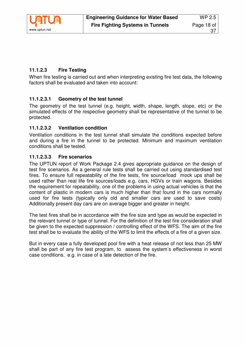
Fire Tests during UPTUN Program (Photo Courtesy of FOGTEC, Germany)
Fire sizes which can be expected in road tunnels are 4 - 6 MW6 per car and 200 MW7 per HGV. For car fires it shall be assumed that at least 6 cars may be involved in a fire. Since trains may vary considerably with regards their potential fire load it is recommended to carry out calculations on a case by case basis.
11.1.2.3.4 Activation
For testing purposes the WFS shall be activated manually. The time between the ignition of the fire and activation shall be defined by appropriate engineering methods. To ensure that fire tests are carried out realistically , consideration shall be given to the time taken for a fire detection system to detect a fire after ignition and/or to a CCTV system or thermal cameras which may be used by qualified tunnel personnel in charge of manual activation. Any other aspects relevant to the time of activation of the WFS shall also be considered. The manufacturer of the WFS shall specify the method(s) of activation of his product prior to testing.
6 Steinert C., Experiments on the burning properties of cars and related fire propagation. Vfdb – Magazine 4/2000, pp 163 - 172 7 Innagson, Lönnermark, Large scale fire tests in the Runehamar Tunnel - Heat release rate. Proceedings of the International Symposium on Catastrophic Tunnel Fires, Boras (Sweden) 2003

www.uptun.net
Engineering Guidance for Water Based WP 2.5
Fire Fighting Systems in Tunnels Page 20 of 37
11.1.2.3.5 WFS
The WFS used during the fire tests shall be installed according to the manufacturer’s installation guideline. Nozzle types, positioning of nozzles, minimum and maximum pressures, section lengths, time to activation, time to full operation after activation and all other main parameters of the system used for testing shall be identical with the system to be used in a tunnel to be protected. The WFS shall be tested with the max. and the min. allowable pressure at the nozzles.
11.1.2.3.6 Third Party supervision
All tests shall be supervised by an accredited independent third party. The third party shall be experienced in the field of carrying out full size fire testing in tunnels and shall be familiar with the requirements for tunnel safety. The final test report shall be prepared and signed by the third party. The test report shall include, at the very least, details of the following: - name and address of test laboratory - name and address of the independent third party that has been considered
acceptable by the authorities having jurisdiction. - detailed drawings of the test tunnel - detailed drawings of the tested WFS - layout parameters for the tested WFS - type and size of fire loads - method of ignition of fire loads - details of the position of the fire loads in the tunnel - preburn time - method of activation of the WFS - ventilation conditions (type, velocity) - temperatures continuously before, during and after testing in distances of 5 m, 10 m,
20 m and 40 m on the downstream side and in distances of 5 m, 10 m, 20 m and 40 m on the upstream side; distances shall be measured from the end of the fire load; temperatures shall be measured at two positions in the cross section of the tunnel at heights of 1 m, 2 m, 3m above the road surface and 0,15 m below the ceiling. Alternative arrangements of the measuring equipment, which will provide the same level of information, shall be acceptable.
- radiant heat continuously before, during and after testing at both ends of the activated WFS section.
- O2, CO2 and CO concentration continuously before, during and after testing approx. 40 m at the downstream side of the fire over the cross section.
- visibility in the tunnel before, during and after the tests
11.1.2.4 Computer Simulations
Appropriate computer based simulations to replace full size fire tests are not expected to be available in the nearer future. Computer simulations may only be used to interpret data retrieved from full size fire tests.

www.uptun.net
Engineering Guidance for Water Based WP 2.5
Fire Fighting Systems in Tunnels Page 21 of 37
11.1.2.5 Extrapolation and Interpolation
When interpreting fire test data for the specification of layout parameters extrapolation of such data shall be restricted and used very cautiously, based on sound engineering methods which are considered acceptable by the authorities havinng jurisdiction. Interpolation of test data is less critical but should be carried out with the same level of engineering methods. In all cases the designer of a system shall ensure that the fire test data and thus the conditions during the full size fire tests, on which the layout parameters are based upon, are representative of the relevant tunnel to be protected. It is not necessary to carry out a separate series of fire tests for each individual tunnel to be protected. In case that the conditions applied during a fire test series is applicable to more than one particular tunnel, the same test data may be used for all tunnels having the same major conditions being relevant to the efficiency of the WFS.

www.uptun.net
Engineering Guidance for Water Based WP 2.5
Fire Fighting Systems in Tunnels Page 22 of 37
11.2 Detailed Design Good engineering practice shall be the basis for the detailed design of the WFS. Sufficient safety margins shall be foreseen for all aspects of the design. The outcome of the design process shall be a well engineered and reliably working WFS. Taking into account the overall layout parameters of the WFS, the detailed design shall ensure that the WFS supplys the full flow rate of water to all nozzles in any two sections simultaneously no later than 60 seconds after activation. All nozzles installed in these two sections shall operate at full capacity after this time. All components of the WFS shall be properly dimensioned. The reliability of the components used is vital for the safe functioning of the WFS. Thus the environmental conditions found in the relevant tunnel must be considered to compensate for effects of salt, humidity, change in temperatures, pollution etc. Third party testing and listing of safety relevant components shall be ensured. Further aspects which shall be considered are: - expected life time - life cycle costs (LCC) - FMEA, Fault Tree analysis - MTTF - cost to recommission the WFS after a (false) activation
11.2.1 Water Reservoirs
The water reservoir shall be capable to provide water for at least 30 minutes of operation under worst case conditions for tunnels not longer than 500 m and for 60 minutes for tunnels longer than 500 m the operational period may be longer, see Section 9. This will be sufficient to supply water to the two adjacent sections, which form the protection area with the greatest demand, for the aforementioned period. The size of the water reservoir is calculated using the following formula:
totalactivationwater QtV ⋅=
Vwater Needed water volume [liter]
tactivation Designed maximum activation time [min]
Qtotal Total pumping capacity [l/min]
Water reservoirs shall be of stainless steel, coated carbon steel, plastic or coated concrete to avoid contamination of the water with rust or particles origining from the tank structure itself.

www.uptun.net
Engineering Guidance for Water Based WP 2.5
Fire Fighting Systems in Tunnels Page 23 of 37
Water tanks shall be supervised for the following conditions: - water level - water temperature (for tanks located in unheated areas). Reservoirs shall be provided with a drain valve and an overflow outlet. A manual ball valve shall be placed in the outlet of the reservoir for maintenance purposes. Reservoirs shall be provided with a venting to the atmosphere to avoid over/under pressure. This venting shall be protected by a breather filter to prevent the infiltration of particles into the reservoir. The reservoir shall be labelled with its volume.
11.2.2 Filtration
Filtration is of great importance to the WFS functioning reliably.
11.2.2.1 Pre-Filtering
Water shall be pre-filtered when filling up the water reservoir. For this purpose filters with a filtration grade of not higher than 150 micron shall be installed at the tank inlet.
11.2.2.2 Main Filter
Suitable filter means shall be provided between the reservoir and the pump unit, of a filtration grade according to the table shown in chapter 11.2.5.2, to prevent particles which may have built up in the reservoir over time entering into the supply system. Such filters shall: - be 100% redundant or self cleaning - provide a by-pass for the case of blocking - be monitored - have a sufficiently large filter surface.
11.2.2.3 Nozzle Filters
Each nozzle or nozzle head shall be equipped with a strainer. The size of the strainer and the width of the mashes shall correspond with the water ways in the nozzles.
11.2.3 Quality of material in contact with water
Chloride and other reactive substances commonly contained in water may cause severe corrosion to low-level stainless steel materials if they are used in the WFS for parts which come into contact with water, such as forming part of the water supply, upstream or downstream. Therefore all parts and components of the water supply including but not limited to valves, pipe work, pumps and filters shall be of stainless steel of a quality of at least 1.4571 / AISI 316 Ti. Alternatively components like filters may be of non corrosive material like plastic. NOTE: Carbon steel protected by Zinc plating or any other coating shall not be used due to the long design life of the WFS.

www.uptun.net
Engineering Guidance for Water Based WP 2.5
Fire Fighting Systems in Tunnels Page 24 of 37
11.2.4 Booster Pump
In the water supply line between reservoir and pump unit after the main filter a booster pump shall be foreseen to ensure the required pressure of the supply from the reservoir. The booster pump shall be installed with a redundancy of 100% or shall be equipped with an automatic by pass for the case of a failure of the booster pump.
11.2.5 Pump Units
The flow rates necessary in tunnels are high which makes the pump unit design more specialized than that for standard WFS applications. Pump units shall consist of one or more pumps which are driven by either electrical or diesel motors. As good engineering practice, only direct couplings between motor and pump shall be used. In addition only one pump per motor shall be used. Multiple drives, e.g. one motor with two pumps as well as gears, chain or belt drives shall not be used in fire protection. The only exception is the integration of a reduction gear with the crankcase of the pump, which is normally necessary for pumps of higher flow capacity.
11.2.5.1 Pump Capacity
The total capacity of the pump unit shall be 110% of the amount of water required to supply the protection area (most demanding two or more adjacent sections) at the minimum pressure specific to the nozzles.
min1.1 pKnQ vnozzleswater ⋅⋅⋅=
Qwater Necessary pumping capacity [liter/min]
nnozzles Number of activated nozzles [-]
Kv Kv-factor of nozzles [liter/(min √bar)]
Pmin Minimum pressure at nozzles [bar]
When calculating the total flow rate only the effective flow rates shall be used. This means that the volumetric efficiency of the pump(s) has to be taken into account. For positive displacement pumps it is common practice for manufacturers to only inform about theoretical flow rates with 100% efficiency. Using the following formula the effective capacity can be calculated:
ltheoreticavolumetriceffective QQ ⋅=η Qeffective Effective flow rate of pump [liter/min]
ηvolumetric Volumetric efficiency of the pump [-]
Qtheoretical Theoretical flow rate of pump [liter/min]
Centrifugal pump sets shall be designed and installed in accordance with the requirements of EN 12845 and EN 12259-12.

www.uptun.net
Engineering Guidance for Water Based WP 2.5
Fire Fighting Systems in Tunnels Page 25 of 37
Triplex Plunger Pump, 140 bar, 500 l/min (Photo Courtesy of KAMAT, Germany)
11.2.5.2 Pump Types
The following table gives an overview of the most common pump types:
Pump type Pressure / flow rates
Flow rate Pressure
fluctuations Filtration
Safety valve
Centrifugal pumps
<40 bar, >1000 l/min
Variable as function of pressure
No Very tolerant
>250 µm Not needed
Axial piston pumps
<210 bar, <350 l/min
Constant Small (depends on number of
pistons)1
Sensitive <50µm
Needed
Inline plunger (/piston) pumps
2 <3000 bar, <3000 l/min
Constant Small (depends on number of
plungers)3
Tolerant <250µm
Needed
Pressure intensifiers
4 >4000 bar, <800 l/min
Constant High Tolerant <150 µm
Needed 1Normally 5, 7 or 9 pistons.
2Normally mostly triplex plunger pumps, but if low pressure and high flow rate then piston pumps can be used.
3Normally 3 plungers.
4 Needed high pressure hydraulics or pneumatics available.
The recommended pump type for most tunnel applications is the triplex plunger pump, because the available flow rates cover normal tunnel requirements. In addition, the constant high pressure level, tolerant suction conditions and low filtration requirements are benefits when compared to other pump types.
11.2.5.3 Multiple Pumps and Redundancy
It is recommended to limit the number of pumps used in fire protection systems mainly because of the following reasons: The complexity of systems and the lifetime costs. A large number of pumps will lead to complex pump unit arrangements and interactions between pumps, and, a greater number of parts that will be subject to wear. The more moving parts a pump unit consists of the greater potential risk of failure. The greater the number of moving parts, and components in general, for a pump system will increase the maintenance and lifetime costs. The optimum design would be only one pump per system (plus a stand-by pump), however, due to the high flow requirements in tunnels this is normally impossible to realize. The necessary redundancy level is another factor which dictates the use of more than one pump.

www.uptun.net
Engineering Guidance for Water Based WP 2.5
Fire Fighting Systems in Tunnels Page 26 of 37
These two important factors, redundancy level and complexity/maintenance index with different pump concepts, are compared in the following table.
Pumps Flow rate
1 (compared
to requirement) Operation level if one pump
won’t work2 Complexity / Maintenance index
3
1 110% = 110% 0% 100% 2 2x55% = 110% 55% 180% 3 3x36.66% = 110% 73.3% 270% 4 4x27.5% = 110% 82.5% 360% 5 5x22.5% = 110% 87.5% 450%
10 10x11% = 110% 99% 1900% 2+1
4 2x55% = 110% (+55%) 110% 270%
1Normally designed capacity is minimum +10% compared to maximum need
2Commonly used redundancy requirement.
3Index compares one pump to multiple pump systems, which is almost proportional to number of wearing parts.
4Additional stand-by pump The redundancy requirement shall be 100% operation with the failure of . This requirement can only be fulfilled if a stand-by pump is provided . However, the number of pumps to the system should still be limited even including the stand-by pump(s). As per common practice the maximum number of pumps shall be limited to 5 or less in order to keep the complexity and lifetime costs at reasonable levels (see table). Recommended pump arrangements with redundancy are combinations of 3+1 up to 5+1. Only if the power requirement of an individual pump exceeds 200kW should more pumps be considered. The stand-by pump shall have the capacity to compensate for the loss of any single supply pump. A single failure of any of the components of the pump system shall not result in the failure of the WFS to operate. For tunnels exceeding 1000 m in length the installation of more than one pump system shall be considered, to increase redundancy.
11.2.5.4 Safety Valves
Each individual pump shall be equipped with a safety valve set at 115% of the operating pump pressure. The Safety valve shall allow for the discharge of the full flow capacity. Alternative designs shall only be acceptable after full consideration of reliability and life safety aspects.
11.2.5.5 Type of motor / Power Supply
Due to their independence from an external power supply diesel motors are the preferred type of driver for WFS in cases where back up electrical power supply cannot be provided. Only if technical reasons derived by a proper engineering analysis exclude the use of diesel motors, shall electrical drives be considered. In case that electric motors of the pump units are used the electrical power supply shall be redundant with automatic switch over. The two supplies shall not be routed through the protected areas. Only if protected by structural fire protection means with a suitable rating shall one of the two independent supplies be routed through the area.

www.uptun.net
Engineering Guidance for Water Based WP 2.5
Fire Fighting Systems in Tunnels Page 27 of 37
The electrical power supply systems shall comply with the latest relevant standards for high voltage applicable in the respective jurisdiction.
11.2.5.6 Pump Room
Pump rooms should always be kept at a temperature above 4°C in order to prevent freezing. Rooms should be equipped with a suitable drainage and ventilation
11.2.6 Jockey Pump
To ensure that the WFS is operating in the relevant section(s) not later than 60 sec. after activation it is recommended to pre-fill the main pipe up to the section valves. A jockey pump or a multiple of such shall be used to pressurise the main pipe to a suitable stand-by pressure. The jockey pump(s) compensates for small leaks. Any major leakages can be detected by monitoring the stand by pressure. Jockey pumps work relatively often and therefore it is good practice to arrange a self cleaning filter to ensure faultless operation.
11.2.7 Pipe work8
11.2.7.1 Hydraulic Calculation
The pipe work shall be dimensioned to ensure that at least the minimum pressure tested in the relevant full size fire tests is achieved at all nozzles of the activated sections in any part of the tunnel. The maximum allowable pressure loss shall be within the limits given by the max. and min. tested pressure. For the calculation of pressure loss, suitable software, which is acceptable to the authorities having jurisdiction, shall be used. For details of the calculations refer to NFPA 750. As part of the commissioning of the WFS a spray test shall be carried out in the area most hydraulically demanding to prove the achieved pressure For this purpose all sections forming this area shall be activated simultaneously.
11.2.7.2 Material
Pipe material shall be tolerant against corrosion. Typically, the environment in tunnels is harsh due to the pollution created by traffic and road salt where applicable. The minimum requirement is 1.4571/AISI316Ti. The material requirement is the same for all pipe connectors (basically, the fittings and flanges). All parts of the connectors shall be made of stainless steel in order to maximize the corrosion resistance and life time in tunnel environment. To avoid the risk of galvanic corrosion the use of stainless steel and carbon steel materials in the same piping connector is not permitted even if carbon steel is plated.
8 See for details: Max Lakkonen, Water Mist Systems and Industrial Water Hydraulics – Similarities and Differences from Technical and Design Point of View, International Water Mist Conference, Berlin, 2005

www.uptun.net
Engineering Guidance for Water Based WP 2.5
Fire Fighting Systems in Tunnels Page 28 of 37
11.2.7.3 Connectors
Commonly used fittings and flanges may be used as connectors provided that they comply with 10.2.7.2 and that they are suitable for the: - operating pressure - expected vibrations - expected heat - environmental conditions - variations in temperature - and shall be able to withstand anticipated dynamic and static forces If welding is used only certified and qualified welders shall be used. The thermal expansion and movement of pipes shall be considered.
11.2.7.4 Dimensioning
The wall thickness of pipes shall be dimensioned according to the maximum working pressure.
11.2.7.5 Protection against Freezing
The main pipe shall be maintained at a minimum temperature of 4°C. Where the environmental conditions do not ensure this, a suitable pipe and valve heating system shall be used. Alternatively, anti-freeze additives may be used. In this case it shall be demonstrated to the satisfaction of the authorities having jurisdiction that the additive does not have an adverse effect on fires. In addition additives shall be non-hazardous to people’s health.
11.2.7.6 Pipe supports
Pipe supports shall be in accordance with ISO 6182-11. Otherwise the manufacturer shall prove that the following basic requirements are complied with: - load - vibration - water hammer - heat resistance Pipe supports shall be suitable for the environmental conditions, for the expected temperature, including the stresses induced in the pipe work by temperature variations, and be able to withstand the anticipated dynamic and static forces.
11.2.7.7 Thermal expansion
The thermal expansion and movement of pipes shall be considered and compensated for. Pipe loops are the recommended method for thermal expansion compensation.

www.uptun.net
Engineering Guidance for Water Based WP 2.5
Fire Fighting Systems in Tunnels Page 29 of 37
11.2.8 Flushing and Pressure Testing
After installation the entire pipe work shall be suitably flushed to clean it from any residues. For this purpose only experienced personnel and dedicated pipe cleaning machinery shall be used. The pipe work shall be free of any particles and substances such as oil before putting it into operation. NOTE: Improper pipe cleaning may result in blockage of nozzles and corrosion of pipe work. Before commissioning of the WFS all pipe work shall be pressure tested to 150% of the maximum working pressure for one hour.
11.2.9 Section Valves
Section valves shall be robust, remotely controlled and fully leakage free. Therefore only ball valves shall be used. Valves should be equipped with an adequate drive. This can be either pneumatic, water hydraulic or electric. Valves shall not be activated by thermal elements. Sections valves shall be provided such that a monthly test operation can be carried out without allowing water to flow from the main pipe to the relevant section. If sections valves are installed inside the tunnel they shall be protected by enclosures with a suitable fire rating. Section valves should be equipped with suitable shut off means, which allow the replacement of a section valve without draining water from the main pipe.
11.2.10 Nozzles
To prevent damage to nozzles and pipe work caused by an accident and to avoid parked vehicles obstructing the spray of the nozzles, nozzles shall in no case be installed at the lower level of the side walls, neither shall they be installed at road level The minimum recommended height for installation is a height greater than the height of the tallest vehicle expected in the tunnel. . All nozzle openings shall be protected against contamination and clogging by suitable means such as nozzle caps. It shall be ensured that such means are safely propelled off at a pressure of at least 25% lower than the min. operating pressure of the nozzle. Best practice is to protect each individual nozzle separately instead of a common protection cap for the whole nozzle head if multiple orifice nozzles (heads) are used. The benefit of this is that in case of a malfunction caused by various possible reasons, only one of the orifices would not operate compared to the whole nozzle head not operating.

www.uptun.net
Engineering Guidance for Water Based WP 2.5
Fire Fighting Systems in Tunnels Page 30 of 37
11.2.11 Activation
As a minimum, it shall be possible to activate the WFS manually from the tunnel control room or a similar suitable location. Additionally the WFS can be activated automatically by a dedicated detection system. In case that both activation modes are available, the manual activation shall override the automatic activation. Thus, manual activation shall also be possible in scenarios in which the detection system has not detected a fire. For automatic activation, it is recommended that a WFS activates only when two detectors are triggered. Thus, the first signal received from the detection system shall only trigger a pre-alarm, the second signal shall activate the WFS. This should ensure that the operation of the WFS, by false alarm, will be avoided. Alternatively the WFS may be activated after the first signal from the detection system and a second signal from manual activation means, whereby the fist signal activates the pump(s) and the manual activation shall open the respective valve(s). In case of activation of the WFS the following actions shall be initiated: - start-up of the (relevant) booster pump(s) - start-up of the (relevant) pump unit(s) - opening of the respective section valve(s) - operation of all nozzles in the respective section - activation of an audible and visual alarm in the pump room(s) and any tunnel control
room(s) NOTE: In case of a manual activation, the above actions shall be initiated by a single signal by the control system or the detection system respectively. E.g. in case of manual activation the triggering of a maximum of one switch per section shall be required to put the WFS in proper operation with all its necessary functions.

www.uptun.net
Engineering Guidance for Water Based WP 2.5
Fire Fighting Systems in Tunnels Page 31 of 37
11.2.12 Control Systems
Normally, the central control system of a tunnel is used for the control and monitoring of technical equipment such as lighting, ventilation, traffic signs and energy control. The following sub systems of such control systems are required for the reliable functioning of the WFS: - detection system - pump control system - valve control system The RABT guideline9, Chapter 3 shows how to design such control systems. The redundancy of all components necessary for the WFS to operate successfully must be taken into account. . Any failure of a component of the control system shall not result in a reduction of the capacity of the WFS by more than 50%. The WFS can be integrated as shown below:
9 Guideline for equipment for road tunnels and tunnel operation, issued by Research Establishment for Roads and Traffic e.V., Cologne
…??? WFS control system
Control unit
CCTV
Fire control panel
Pumps Tank
…
Section Valves
Linear heat
detection
Cameras
PROFIBUS according to DIN 19245 (EN 50170) as ring systems
Central Control Unit
Printer
Monitor
Control panel
Data-base …???
LAN

www.uptun.net
Engineering Guidance for Water Based WP 2.5
Fire Fighting Systems in Tunnels Page 32 of 37
These sub-control systems are safety relevant systems and shall be installed tested and maintained in accordance with appropriate national standards as well as with relevant European standards.10
11.2.13 Detection Systems
The chosen detection system shall be approved for the use in tunnels. Consideration shall be given to the fact that heat and smoke may be transported away from the location of the fire by moving air. The detection system shall activate the section valves. It shall further monitor: - the position of any valve in the upstream and downstream water supply - any maintenance isolation switch - the power supply to the pump unit (electrical motors only) - general fault of the pump control system
10 E.g. 72/23/EWG and 93/68/EWG with EN 61000-6-1 Part 2 and 97/37/ EG with EN 60204 Part 1

www.uptun.net
Engineering Guidance for Water Based WP 2.5
Fire Fighting Systems in Tunnels Page 33 of 37
11.2.14 Pump Control System
A single failure of any of the controls shall not result in the failure of the WFS to operate. In case that one control system is used to control an entire pump system which consists of multiple pumps, a second stand-by control system shall be provided. In case that individual pump control systems are used for multiple pumps and one stand-by pump is installed, the respective pump control system of this stand-by pump shall be considered to be sufficient. The following functions shall be monitored by the pump control system: For Diesel driven pumps - pump running - power failure - controller not in automatic position - low oil pressure - high water temperature - failure to start/overcrank - over speed - fuel level (set at 75 % capacity). For electrical pumps - pump running - loss of power - phase reversal - controller not in automatic position - running meter (hours of operation per pump) Additionally, WFS shall be equipped with manual activation means at the pump control system, at the detection system and – if applicable – in the tunnel control room. This also applies to WFS normally activated automatically by a detection system.
11.2.15 Valve Control
Section valves shall be activated either automatically based on signals from the detection system or manually from a control room manned by trained personnel.

www.uptun.net
Engineering Guidance for Water Based WP 2.5
Fire Fighting Systems in Tunnels Page 34 of 37
11.3 Additives Foam or film building additives may be applied to enhance the effects of the water used by the WFS to suppress/control a fire. In such cases the WFS shall have been tested according to 11.1.1.1 using the same type and percentage of additive. The use of additives for frost protection shall be allowed. They shall not be of the Glycol type to avoid negative effects when applied in small droplets in a hot environment. Further additives to prevent biological growth in the stored water in the reservoir or the main pipe may be used. For all additives suitable proof shall be provided that the water / additive mixture will have no negative effect on humans when being applied in the respective droplet size class according to 11.1.2.1.
www.uptun.net
Engineering Guidance for Water Based WP 2.5
Fire Fighting Systems in Tunnels Page 35 of 37
11.4 System Documentation The documentation of a WFS should at least include the following: - fire protection concept - system layout with third party test reports and expertise accordingly - plan and sectional view of the protected area showing the lay-out of:
- zone divisions, size and locations; - all piping, nozzles and all hangers and supports; - all devices of the alarm and control system; - all controlled devices, such as dampers, shutters, valves etc.; - all warning and instruction signs;
- hydraulic calculations - isometric drawings - flushing and pressure testing reports by section - detailed description of function - operation instructions - maintenance instructions - installation acceptance certificate of a third party acceptable to the authorities having
jurisdiction (e.g. STUVA, TÜV, CETU, SINTEF, TNO)

www.uptun.net
Engineering Guidance for Water Based WP 2.5
Fire Fighting Systems in Tunnels Page 36 of 37
12 Maintenance
A strict and regular maintenance programme shall be followed to ensure the reliable operation of the WFS. The operator of the system shall be responsible for this programme. Maintenance shall be carried out in accordance with the design, installation and maintenance manual of the manufacturer. The regular maintenance shall at least cover the following: - monthly pump test runs for a minimum of 10 min. without pressurizing the pipe work
in the tunnel; where applicable, all pumps of one pump unit shall be tested simultaneously
- monthly test of all section valves (test by operation) NOTE: Section valves do not normally have any redundancy.
- monthly collecting of information on running times of jockey pumps and automatic filters in order to detect leaks and water quality problems.
- quarterly visual inspections of piping and nozzle heads - twice a year (minimum) the system shall be maintained in accordance with the
manufacturer's instructions by a company authorised by the manufacturer. - every five years pressure testing of the pipe work with 150% of the working pressure
for one hour. The operator's inspection programme is intended to detect faults at an early stage to allow rectification before the system may have to operate. The manufacturer shall provide the tunnel operator with a monitoring software collecting the history of service and maintenance activities, running times of the pump system, failure reports etc. The software shall include instructions on actions to be taken in case of faults and malfunctions. The relevant requirements of EN 12845 and EN 15004-1 shall be followed where applicable.

www.uptun.net
Engineering Guidance for Water Based WP 2.5
Fire Fighting Systems in Tunnels Page 37 of 37
13 Spare Parts
In the pump room or another suitable room spare parts for the WFS shall be kept. These shall include as a minimum: - All wearing parts of the main pump system. In case that a multiple pump unit is
used, wearing parts for a least one pump set shall be stored. - All wearing parts of the jockey pump system. - All wearing parts of the booster pump system. - Filter elements for all filters in the pump room - One unloader valve where applicable - One safety valve where applicable - Section valves with cabinets where applicable for three sections - Nozzles for two full sections - Main components of the control system such as the CPU and a software back up For tunnels with a length of less than 500 m the requirements of this section may be lowered in accordance with the authorities having jurisdiction.
14 Training
All persons who may be expected to inspect, test, maintain or operate the WFS shall be trained and kept adequately trained in the functions they are expected to perform. Proper documentation of their regular training shall be kept in the tunnel control room or a place easily accessible for the authorities having jurisdiction.
15 Requirements on Contractors
The company taking charge of the project implementation should be an erector experienced in the installation of WFS. Bidders should be required to submit the corresponding references and proof of expertise prior to commencement of work. Such experience shall include the installation of a WFS in tunnels. 24 h on-call duty as well as a 24-h response time shall be guaranteed. The manufacturer and erector as well as their major subcontractors and suppliers shall be certified to ISO 9001-2000 for the complete volume of services and supplies. Furthermore, the quality of planning and erection documentation and drawings as well as hydraulic calculations shall be verified.
16 DISCLAIMER
All above information, guidance, recommendations and data have been generated and compiled with reasonable care. It is the reader’s sole responsibility to verify in every individual case whether the content of this document is suitable for and may be used in connection with a relevant project. The reader is deemed to be an expert in the field of fire protection in tunnels.