work loss in double-inlet pulse tube refrigerators
TRANSCRIPT
Cryogenics38 (1998) 803–807 1998 Cryogenic Association of Japan. Published by Elsevier
Science Ltd. All rights reservedPII: S0011-2275(98)00065-4 Printed in Great Britain
0011-2275/98/$—see front matter
Work loss in double-inlet pulse tuberefrigerators1
Shaowei Zhu*, Shin Kawano, Masahumi Nogawa and Tatsuo Inoue
2nd Development Department, Corporate R and D Sector, AISIN SEIKI CO. LTD. 2-1,Asahi-machi, Kariya, Aichi 448-8650, Japan
Received 19 February 1998
An analytic equation of the mass flow rate through the bypass of double-inlet pulsetube refrigerators was obtained by an analysis of the pressure drop in the regenerator.The work loss through the bypass is discussed based on this equation. The work lossdecreases with the increase of the void volume ratio of the regenerator over the pulsetube, decreases with the increases in temperature ratio of the room temperature overthe refrigeration temperature, and increases with the increase in ‘double-inlet factor’which is introduced in this paper. The work loss ratio at 80K with an ideal double-inletis about 50, 30, 20 and 10% when the void volume ratio of the regenerator over thepulse tube is 0.5, 1.0, 2.0, and 4.0, respectively. The analytic results were comparedwith numerical results. A good agreement between them was achieved. 1998Published by Elsevier Science Ltd. All rights reserved
Keywords: cryocooler; pulse tube refrigerator; double-inlet; work loss
V VolumeNomenclatureVP Volume of pulse tube
a = 0. 5mCR/(D2A) VRConstant Volume of regeneratorA VGas flow area of regenerator Volume flow rateb VPConstant Volume flow rate in phase with pressureC waveConstantD WdMean diameter Work loss through bypassf WPFriction factor Work through regenerator to pulse tube forL refrigeration powerLength of regeneratorm xMass flow rate Coordinatemd Mass flow rate through bypassRe Reynolds number Greek lettersR Gas constantP mPressure ViscosityP0 rAverage pressure Densityt tTime PeriodT aTemperature Double-inlet factorT0 bThe temperature at the hot end of Bypass opening coefficientab(T0 + TC)L
regenerator k Specific heat ratioTa gAverage temperature of gas in regenerator Work loss ratio of double-inlet
from 0 to xTc Refrigeration temperature SubscriptTfn Temperature at the interfacenu 0, 1, 2, 3Velocity Interface inFigure 1
*To whom correspondence should be addressed.
Cryogenics 1998 Volume 38, Number 8 803
1Translation of article originally published in Teion Kogaku,1998, 33, 52–58.
Work loss in double-inlet pulse tube refrigerators: S. Zhu et al.
The disadvantage of the double-inlet pulse tube refrigeratoris that there is work loss through the bypass. We call itdouble-inlet work loss. The mass flow rate through thebypass is caused by the pressure drop through the regener-ator. It includes two components. One is in phase with thepressure wave, the other is in a 90° phase with a pressurewave1. The component of the mass flow rate in the 90°phase with the pressure wave is useful for adjusting thephase angle between the mass flow rate and pressure waveat the cold end of the pulse tube. The component of themass flow rate in phase with the pressure wave is the workloss. In this paper, an analytic equation of the mass flowrate through the bypass is obtained from the analysis of thepressure drop of the regenerator. The double-inlet work lossis discussed by this equation. The results are compared withnumerical calculated results. The double-inlet factor isintroduced as a new parameter, which is useful for under-standing the operation condition of the double-inlet pulsetube refrigerator.
The mass flow rate through the bypass line
Figure 1 is the schematic diagram of the double-inlet pulsetube refrigerator. The pressure drop through the regeneratorand heat exchangers is equal to the pressure drop throughthe bypass. From the pressure drop through the regeneratorand the heat exchangers, the mass flow rate through thebypass can be obtained. The following assumptions aremade in order to simplify the analysis.
1. The gas is ideal gas.2. Heat exchangers are neglected. Only the regenerator
and pulse tube are considered.3. In the regenerator, the viscosity of the gas is constant.
The friction factor isf = C/Re. The temperature of thegas is isothermal, and linear distribution. The pressuredrop is small.
4. The bypass line is a tubular configuration. The gas flowis laminar flow. The mass flow rate equation is givenby md = b(P2
2 − P23)
5. The pulse tube space is adiabatic. The gas temperaturesat the cold end and the hot end of the pulse tube areTc andT0, respectively. The gas temperature at the ori-fice is T0.
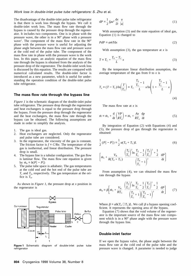
As shown inFigure 1, the pressure drop atx position inthe regenerator is
Figure 1 Schematic diagram of double-inlet pulse tuberefrigerator
804 Cryogenics 1998 Volume 38, Number 8
dP =12
fru2dxD
uuuu
(1)
With assumption (3) and the state equation of ideal gas,Equation (1) is changed to
PdP = amTdx (2)
With assumption (3), the gas temperature atx is
T = TC +T0 − TC
Lx (3)
By the temperature linear distribution assumption, theaverage temperature of the gas from 0 tox is
Ta = (T − TC)/lnS TTCD = TC
T0
TC− 1
Lx/ln11 +
T0
TC− 1
Lx2
(4)
The mass flow rate atx is
m = m1 +ddt SVP
RTaD = m1 +
AxRTa
dpdt
(5)
By integration of Equation (2) with Equations (4) and(5), the pressure drop of gas through the regenerator isobtained:
12
(P22 − P2
1) =12
a(T0 + TC)L (6)
Fm1 +VR
R(T0 + TC)
ST0
TCD2
lnT0
TC−
12 ST0
TCD2
+12
ST0
TC− 1D2
dPdt G
From assumption (4), we can obtained the mass flowrate through the bypass
md = bFm1 +VR
RTC
ST0
TCD2
lnT0
TC−
12 ST0
TCD2
+12
ST0
TC+ 1DST0
TC− 1D2
dPdt G (7)
Whereb = ab(T0 + TC)L. We callb a bypass opening coef-ficient. It represents the opening area of the bypass.
Equation (7) shows that the void volume of the regener-ator is the important source of the mass flow rate compo-nent which is in a 90° phase angle with the pressure wavethrough the bypass line.
Double-inlet factor
If we open the bypass valve, the phase angle between themass flow rate at the cold end of the pulse tube and thepressure wave is changed. A parameter is needed to judge
Work loss in double-inlet pulse tube refrigerators: S. Zhu et al.
the working condition of double-inlet. A double-inlet factoris introduced.
In the pulse tube refrigerator, the volume flow rate at theboth end of the pulse tube have the following relation1,2
V1 = V3 +VP
kPdPdt
(8)
It is obtained from the energy equation in the pulse tube.The second term of Equation (8) is generated by the void
volume of the pulse tube. It is in a 90° phase angle withpressure wave. The basic idea of the double-inlet is to letV1 be in phase with the pressure wave, then the mass flowrate (or volume flow rate) component represented by thesecond term flows from the hot end of the pulse tubethrough the bypass. In real applications the mass flow ratecomponent represented by the second term is not exactlyflowing from the hot end of the pulse tube. There are sev-eral conditions. We assume
V1 = VP + (1 + a)VP
kPdPdt
(9)
where VP is the volume flow rate which is in phase withthe pressure,a is called the double-inlet factor. Thea rep-resents how much of the mass flow rate component causedby the void volume of the pulse tube flows from the hotend of the pulse tube.
From Equations (3) and (4), we can obtain
m3 = VP
PRTf3
− aVP
kRTf3
dPdt
(10)
m1 = VP
PRTf1
+ (1 − a)VP
kRTf1
dPdt
(11)
From Equation (11) there are four conditions.
1. a = 0. All of the mass flow rate component caused bythe void volume of the pulse tube flows into and outof the cold end of the pulse tube. The mass flow rateat the cold end of the pulse tube is not in phase with thepressure wave. It is an orifice pulse tube refrigerator.
2. a = 1. All of the mass flow rate caused by the voidvolume of the pulse tube flows into and out of the hotend of the pulse tube from the bypass. The mass flowrate at the cold end of the pulse tube is in phase withthe pressure wave. We call this condition an ‘ideal dou-ble-inlet’.
3. 0 , a , 1. In this case, part of the mass flow ratecaused by the void volume of the pulse tube still flowsinto and out of the cold end of the pulse tube from theregenerator. We call this condition a ‘partial double-inlet’.
4. a > 1. In this case, all of the mass flow rate caused bythe void volume of the pulse tube flows into and outof the hot end of the pulse tube from the bypass, partof the mass flow rate caused by the void volume of theregenerator also flows into and out of the cold end ofthe regenerator through the pulse tube from the bypass.This condition is similar to the idealized Stirlingrefrigerator. We call this condition an ‘over double-inlet’.
Cryogenics 1998 Volume 38, Number 8 805
The relation between b and a
The mass flow rate through the orifice must equal the totalof the mass flow rate at the hot end of the pulse tube andthe mass flow rate through the bypass, thus
m0 = m3 + md (12)
m0 = V0
PRTf0
= bVP
PRTf1
+ VP
PRTf3
+ b3(1 − a)VP
kRTf1
+VR
RTC
ST0
TCD2
lnT0
TC
−12 ST0
TCD2
+12
ST0
TC
+ 1DST0
TC
− 1D2 4 dPdt
− aVP
kRTf3
dPdt
(13)
The mass flow rate through the orifice is in phase withthe pressure wave, so the third term and the fourth term ofEquation (13) should be equal. Then we get the followingequations from the assumption (5) with whichTf1 = TC, Tf3
= T0, andTf0 = T0.
b =a
(1 − a)T0
TC+ k
T0
TC
VR
VP
ST0
TCD2
lnT0
TC−
12 ST0
TCD2
+12
ST0
TC+ 1DST0
TC− 1D2
(14)
VP = V0
TCT0
T0(TC + bT0)(15)
Equation (14) is the relation betweenb anda. Equation(15) is the relation betweenVP and V0.
For ideal double-inlet, Equation (14) can be changed to
b =1k
1T0
TC
VR
VP
ST0
TC+ 1DST0
TC− 1D2
ST0
TCD2
lnT0
TC−
12 ST0
TCD2
+12
(16)
For ideal double-inlet,b is depend on the void volumeratio of the regenerator over the pulse tube and temperatureratio of the room temperature over the refrigeration tem-perature.
Double-inlet work loss
The work loss through the bypass line which is called dou-ble-inlet work loss and the work through regenerator to thepulse tube for refrigeration power have the followingrelation from Equation (7)
Wd =1t EmdRT0ln
PP0
dt =b
t Em1RT0lnPP0
dt = bWP (17)
The double-inlet work loss can be represented by thedouble-inlet work loss ratiog
Work loss in double-inlet pulse tube refrigerators: S. Zhu et al.
g ;Wd
Wd + WP=
b
b + 1(18)
HereWd + WP is isothermal compressor work. Equation(18) represents how much of the isothermal compressorwork is lost through the bypass. It is related to the tempera-ture ratio of the room temperature over the refrigeration
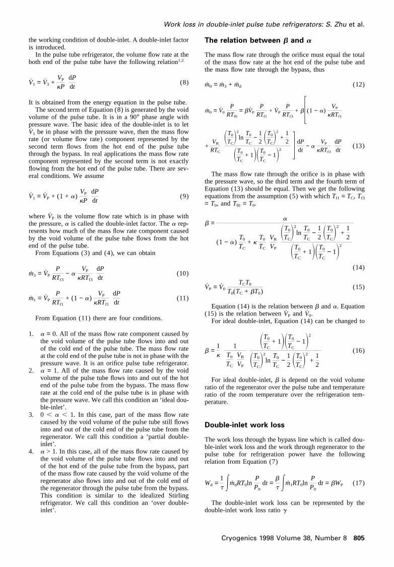
Figure 2 Double-inlet work loss
806 Cryogenics 1998 Volume 38, Number 8
temperature, the void volume ratio of the regenerator overthe pulse tube, and the double-inlet factor.
Figure 2(a)–(d) shows the double-inlet work loss ratiochanges with double-inlet factor with temperature ratioT0/TC 3.75, 5, 7.5, and 15 at four different void volumeratio VR/VP. The working medium is helium gas. The dou-ble-inlet work loss increases with the increase of the dou-ble-inlet factor, decreases with the increase of the void vol-ume ratio of the regenerator over the pulse tube, anddecreases with the increase of the temperature ratio of theroom temperature over the refrigeration temperature. Thedouble-inlet work loss at 80K with ideal double-inlet (a =1) is about 50, 30, 20 and 10% of the isothermal com-pressor work when the void volume ratio of the regeneratorover the pulse tube is 0.5, 1.0, 2.0, and 4.0, respectively.
In order to confirm the above equations, numerical calcu-lated results are used for comparison. The numericalmethod is a third order nodal analysis method without con-sidering inertial effect of the gas. lt is similar to Ref.3. Theroom temperature is 300K. The refrigeration temperature is
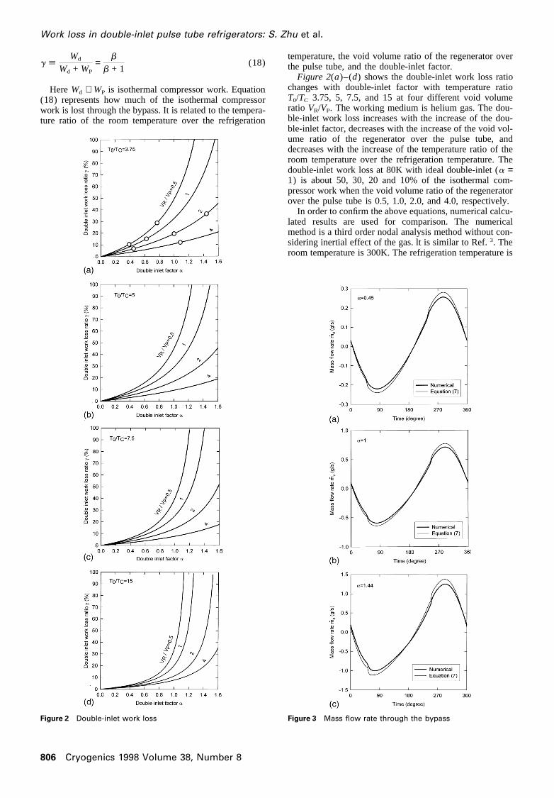
Figure 3 Mass flow rate through the bypass
Work loss in double-inlet pulse tube refrigerators: S. Zhu et al.
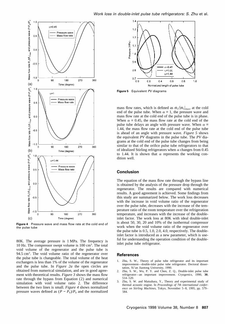
Figure 4 Pressure wave and mass flow rate at the cold end ofthe pulse tube
80K. The average pressure is 1 MPa. The frequency is10 Hz. The compressor swept volume is 100 cm3. The totalvoid volume of the regenerator and the pulse tube is94.5 cm3. The void volume ratio of the regenerator overthe pulse tube is changeable. The total volume of the heatexchangers is less than 1% of the volume of the regeneratorand the pulse tube. InFigure 2a the open circles areobtained from numerical simulation, and are in good agree-ment with theoretical results.Figure 3shows the mass flowrate through the bypass from Equation (2) and numericalsimulation with void volume ratio 2. The differencebetween the two lines is small.Figure 4shows normalizedpressure waves defined as (P − P0)/P0 and the normalized
Cryogenics 1998 Volume 38, Number 8 807
Figure 5 Equivalent PV diagrams
mass flow rates, which is defined asm1/um1umax, at the coldend of the pulse tube. Whena = 1, the pressure wave andmass flow rate at the cold end of the pulse tube is in phase.When a = 0.45, the mass flow rate at the cold end of thepulse tube delays an angle with pressure wave. Whena =1.44, the mass flow rate at the cold end of the pulse tubeis ahead of an angle with pressure wave.Figure 5 showsthe equivalentPV diagrams in the pulse tube. ThePV dia-grams at the cold end of the pulse tube changes from beingsimilar to that of the orifice pulse tube refrigerators to thatof idealized Stirling refrigerators whena changes from 0.45to 1.44. It is shown thata represents the working con-dition well.
Conclusion
The equation of the mass flow rate through the bypass lineis obtained by the analysis of the pressure drop through theregenerator. The results are compared with numericalresults. A good agreement is achieved. Some findings fromthis study are summarized below. The work loss decreaseswith the increase in void volume ratio of the regeneratorover the pulse tube, decreases with the increase of the tem-perature ratio of the room temperature over the refrigerationtemperature, and increases with the increase of the double-inlet factor. The work loss at 80K with ideal double-inletis about 50, 30, 20 and 10% of the isothermal compressorwork when the void volume ratio of the regenerator overthe pulse tube is 0.5, 1.0, 2.0, 4.0, respectively. The double-inlet factor is introduced as a new parameter, which is use-ful for understanding the operation condition of the double-inlet pulse tube refrigerator.
References
1. Zhu, S. W., Theory of pulse tube refrigerator and its importantimprovement—double-inlet pulse tube refrigerator. Doctoral disser-tation, Xi’an Jiaotong University, 1990.
2. Zhu, S. W., Wu, P. Y. and Chen, Z. Q., Double-inlet pulse tuberefrigerator—an important improvement.Cryogenics, 1990, 30,514–520.
3. Zhu, S. W. and Matsubara, Y., Theory and experimental study ofthermal acoustic engine. InProceedings of 7th international confer-ence on Stirling Machines, Tokyo, November 5–8, 1995, pp. 579–584.