wind electric generators(wegs) - eeeforumeeeforum.weebly.com/uploads/1/0/2/5/10254481/weg.pdf ·...
TRANSCRIPT
Wind Electric generators(WEGs)
Dr.V.Vanitha
Assistant Professor(Senior Grade)
Department of Electrical and Electronics Engg.,
Amrita School of Engg.,
Coimbatore
Renewable energy
• Renewable energy is normally defined as theenergy obtained from the natural andpersistent flows of energy occurring in theimmediate environment. Some of therenewable energy sources include wind, solar,biomass, geothermal, hydro and tidal energy.They are replenished in a short time.
Necessity for renewable energy–Demand for electrical power is increasing in
the present scenario.–Conventional methods of generation create
problems like ozone layer damage, globalwarming, high level of emission ofpollutants and ocean acidification
– Electricity generation involves burning offossil fuels which are depleting fast.
–Renewable energy is recognized as vitalinput for sustainability and so encouragingtheir growth is significant. Sustainabledevelopment can be defined as living,producing, consuming in a manner thatmeets the needs of the present withoutcompromising the ability of futuregenerations to meet their own needs.
Advantages of wind energy• Environment friendly and pollution free
• Potential exists to harness wind energy
• Cost of generation decreases over a period of time
• Lowest gestation period and incremental capacity addition
• Low Operation and Maintenance costs
• Mature turbine technologies
• Operational ease and feasibility of full automation
• Efficient and reliable
• Free and inexhaustible source of energy
Disadvantages of wind energy
• Intermittent availability of wind producing avariable energy output
• Low energy density, which requires a largearea to obtain a reasonable amount of energyfrom a wind farm.
• High initial start-up cost
• Noise pollution
• Wind energy needs storage capacity becauseof its irregularities.
Barriers to the development of wind energy
– Lack of robust technical information has lead to opposition to wind farms being developed in certain areas
– Environmental concerns including noise, flickering, wildlife (birds), electromagnetic interference
– Financial incentives and taxation from government are inadequate
– Grid connection issues and wind farm operation
– Transmission constraints
– Low capacity factor (20%-30%)
– Wind forecasting
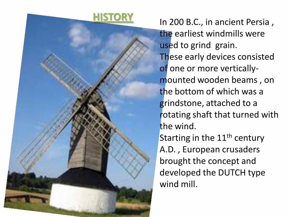
HISTORY In 200 B.C., in ancient Persia , the earliest windmills were used to grind grain.These early devices consisted of one or more vertically-mounted wooden beams , on the bottom of which was a grindstone, attached to a rotating shaft that turned with the wind.Starting in the 11th century A.D. , European crusaders brought the concept and developed the DUTCH type wind mill.
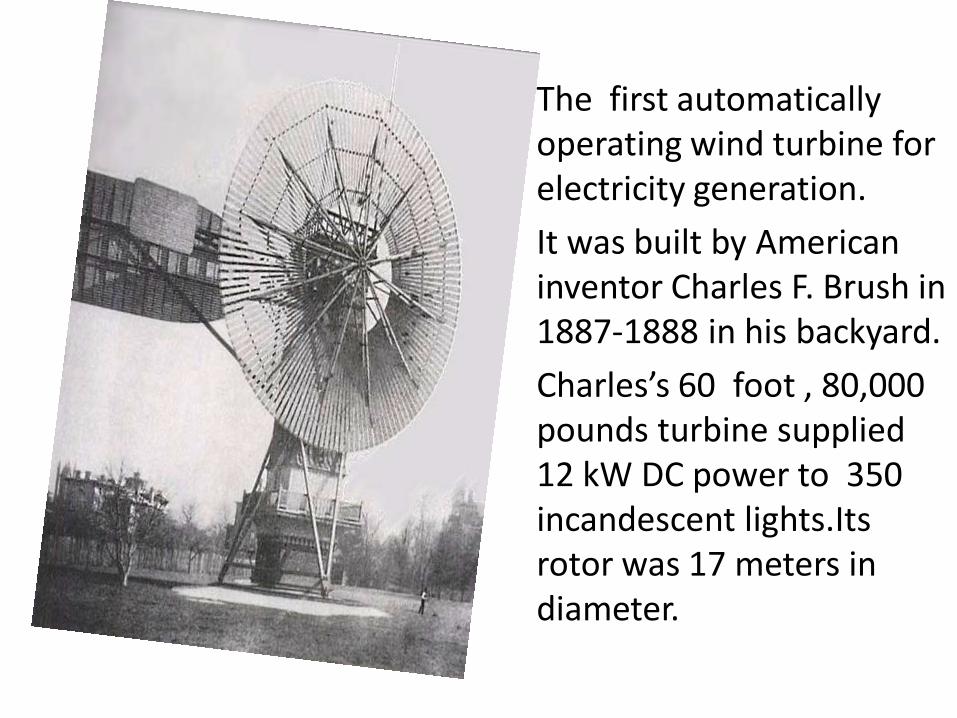
The first automatically operating wind turbine for electricity generation.
It was built by American inventor Charles F. Brush in 1887-1888 in his backyard.
Charles’s 60 foot , 80,000 pounds turbine supplied 12 kW DC power to 350 incandescent lights.Its rotor was 17 meters in diameter.
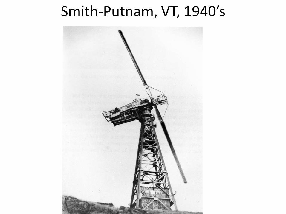
Smith-Putnam, VT, 1940’s
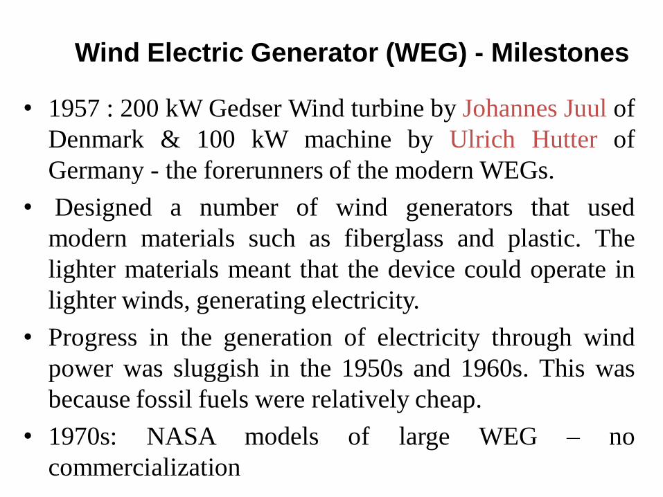
• 1957 : 200 kW Gedser Wind turbine by Johannes Juul of
Denmark & 100 kW machine by Ulrich Hutter of
Germany - the forerunners of the modern WEGs.
• Designed a number of wind generators that used
modern materials such as fiberglass and plastic. The
lighter materials meant that the device could operate in
lighter winds, generating electricity.
• Progress in the generation of electricity through wind
power was sluggish in the 1950s and 1960s. This was
because fossil fuels were relatively cheap.
• 1970s: NASA models of large WEG – no
commercialization
Wind Electric Generator (WEG) - Milestones
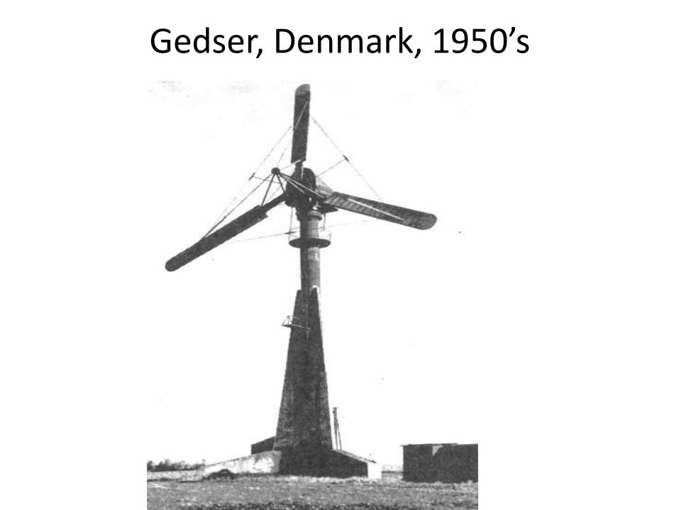
Gedser, Denmark, 1950’s

Wind Electric Generator (WEG) -Milestones
• Due mainly to the fast rise in oil prices throughout the late 1970s and 1980s, AND the fact that using fossil fuels to produce electricity causes pollution, which can damage the environment and cause global warming,
The development of wind generators … ACCELERATED!!!
Wind Electric Generator (WEG) -
Milestones
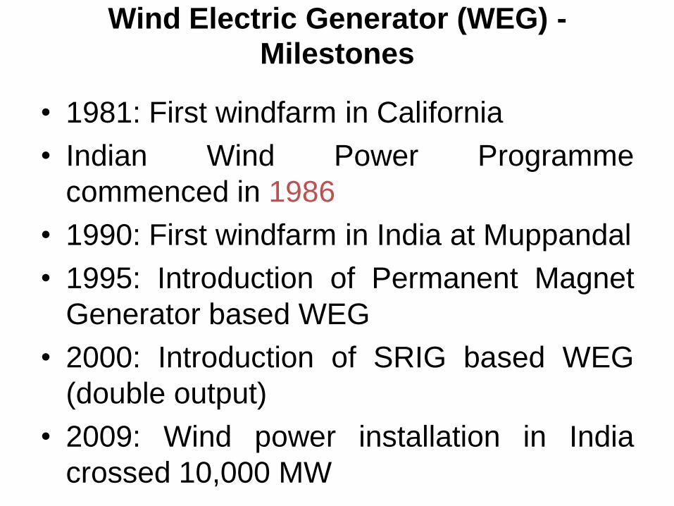
• 1981: First windfarm in California
• Indian Wind Power Programme
commenced in 1986
• 1990: First windfarm in India at Muppandal
• 1995: Introduction of Permanent Magnet
Generator based WEG
• 2000: Introduction of SRIG based WEG
(double output)
• 2009: Wind power installation in India
crossed 10,000 MW
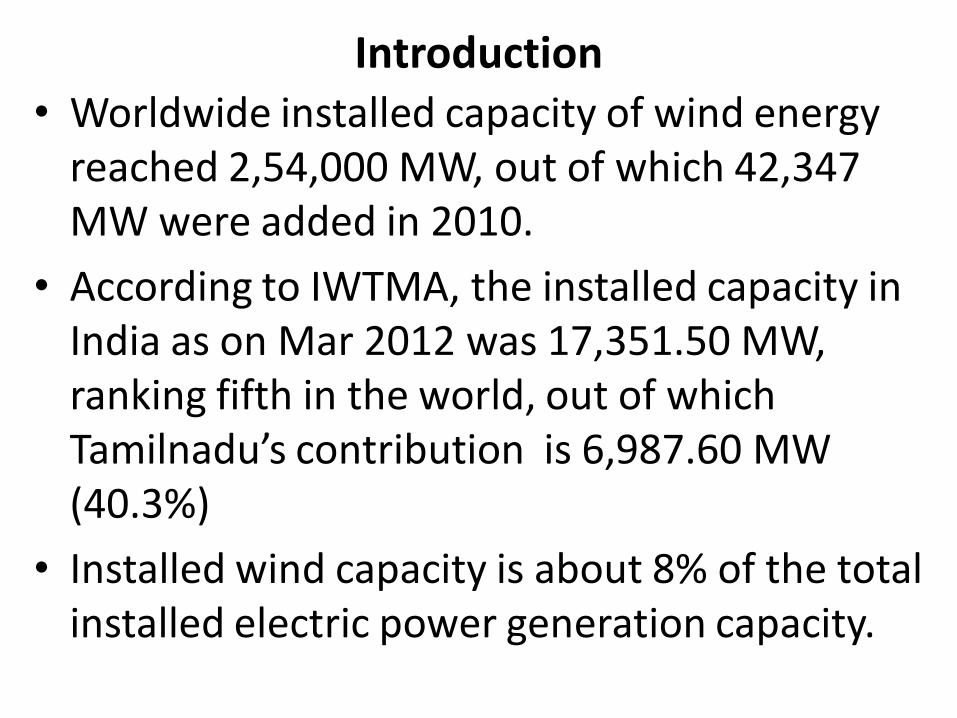
Introduction• Worldwide installed capacity of wind energy
reached 2,54,000 MW, out of which 42,347 MW were added in 2010.
• According to IWTMA, the installed capacity in India as on Mar 2012 was 17,351.50 MW, ranking fifth in the world, out of which Tamilnadu’s contribution is 6,987.60 MW (40.3%)
• Installed wind capacity is about 8% of the total installed electric power generation capacity.

Wind Energy - Global
The world wind capacity reached 254’000 MW by the end of June 2012 - WWEA
3/1/2013 sasi kottayil
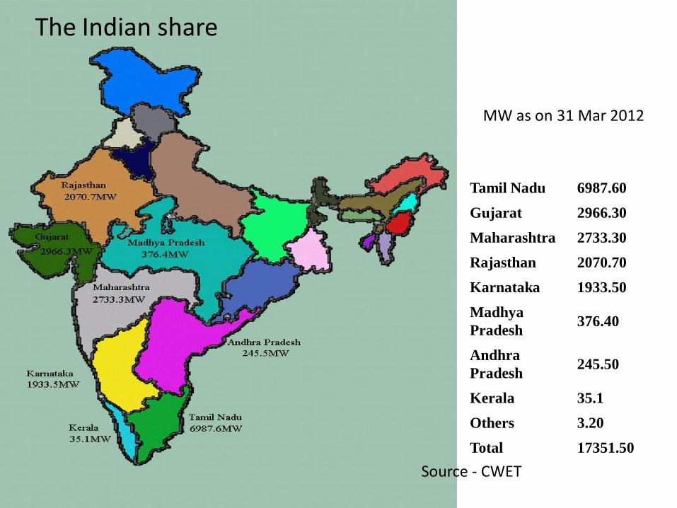
The Indian share
Tamil Nadu 6987.60
Gujarat 2966.30
Maharashtra 2733.30
Rajasthan 2070.70
Karnataka 1933.50
Madhya
Pradesh376.40
Andhra
Pradesh245.50
Kerala 35.1
Others 3.20
Total 17351.50
MW as on 31 Mar 2012
Source - CWET
Introduction
• 26,000 MW is the total Renewable Energy
capacity in India today. 17,351.60 MW is the
total share of wind power (67%)
• 50,000 MW –wind power target for 2020
• 200,000 MW – IWTMA estimated wind
potential in India
• Offshore efforts started at Rameswaram in
2012
Wind energy• All renewable energy (except tidal and
geothermal power), ultimately comes from thesun.
• The earth receives 1.74 x 10¹⁷ watts of power(per hour) from the sun.
• Wind energy is created when the atmosphere isheated unevenly by the Sun, some patches of airbecome warmer than others. These warmpatches of air rise, other air rushes in to replacethem – thus, wind blows.
• About 1 or 2 percent of solar energy is convertedto wind energy (which is about 50-100 timesmore than the energy converted to biomass by allplants on earth).
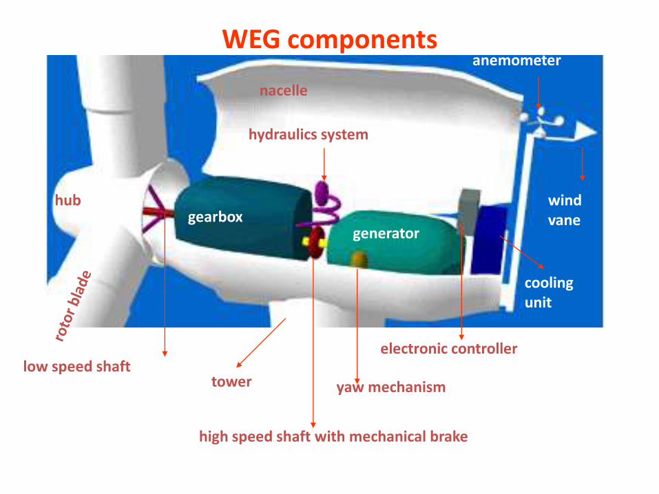
WEG components
nacelle
hub
low speed shaft
gearbox
high speed shaft with mechanical brake
generator
hydraulics system
anemometer
wind vane
cooling unit
electronic controller
tower yaw mechanism
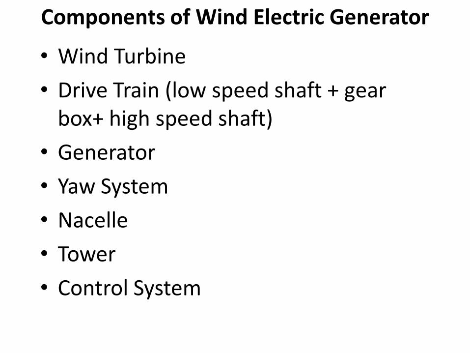
Components of Wind Electric Generator
• Wind Turbine
• Drive Train (low speed shaft + gear box+ high speed shaft)
• Generator
• Yaw System
• Nacelle
• Tower
• Control System
WEG components
The portion of the wind turbine that collectsenergy from the wind is called the rotor. Therotor usually consists of two or morewooden, fiberglass or metal blades whichrotate about an axis (horizontal or vertical) ata rate determined by the wind speed and theshape of the blades. The blades are attachedto the hub, which in turn is attached to themain shaft.
•Blades are connected to a hub, which isconnected to a shaft.
•Rotational speed will depend on bladegeometry, number of blades and wind speed.
•Gear box needed to increase speed to 1200-1800 RPM for generator. Used for stepping upthe speed of the generator, although somedesigns may also use direct drive of an annulargenerator.
WEG components
WEG components
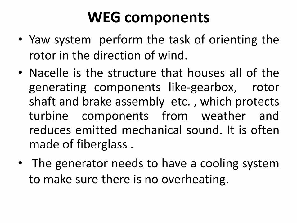
• Yaw system perform the task of orienting therotor in the direction of wind.
• Nacelle is the structure that houses all of thegenerating components like-gearbox, rotorshaft and brake assembly etc. , which protectsturbine components from weather andreduces emitted mechanical sound. It is oftenmade of fiberglass .
• The generator needs to have a cooling systemto make sure there is no overheating.
WEG components
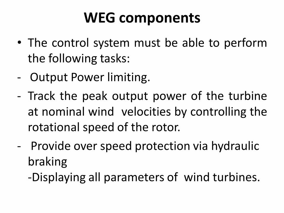
• The control system must be able to performthe following tasks:
- Output Power limiting.
- Track the peak output power of the turbineat nominal wind velocities by controlling therotational speed of the rotor.
- Provide over speed protection via hydraulic braking-Displaying all parameters of wind turbines.
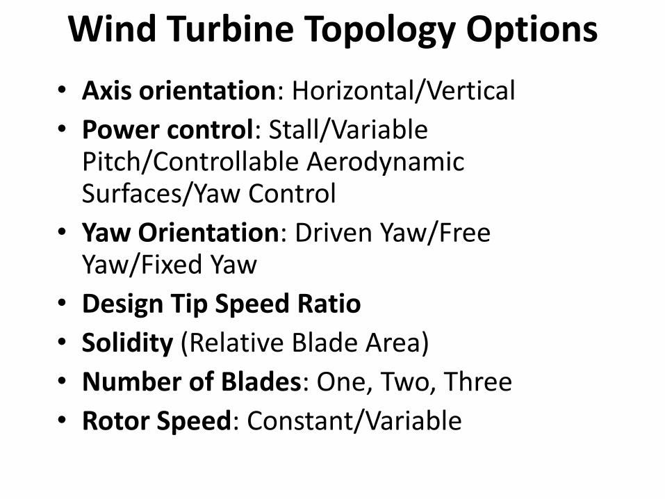
Wind Turbine Topology Options
• Axis orientation: Horizontal/Vertical
• Power control: Stall/Variable Pitch/Controllable Aerodynamic Surfaces/Yaw Control
• Yaw Orientation: Driven Yaw/Free Yaw/Fixed Yaw
• Design Tip Speed Ratio
• Solidity (Relative Blade Area)
• Number of Blades: One, Two, Three
• Rotor Speed: Constant/Variable
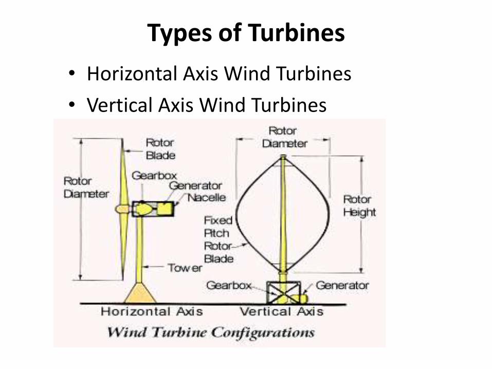
Types of Turbines
• Horizontal Axis Wind Turbines
• Vertical Axis Wind Turbines
HAWTs
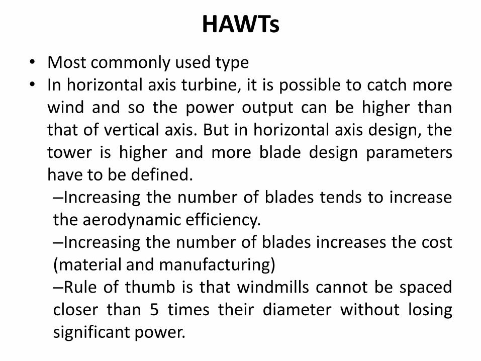
• Most commonly used type• In horizontal axis turbine, it is possible to catch more
wind and so the power output can be higher thanthat of vertical axis. But in horizontal axis design, thetower is higher and more blade design parametershave to be defined.–Increasing the number of blades tends to increasethe aerodynamic efficiency.–Increasing the number of blades increases the cost(material and manufacturing)–Rule of thumb is that windmills cannot be spacedcloser than 5 times their diameter without losingsignificant power.
Blade shape
• A rotor with an even number of blades will
cause stability problems for a wind turbine as
it produces uneven forces on the rotor shaft
and rotor blade. The rotor blade has to betwisted, so as to achieve an optimal angle ofattack throughout the length of the blade.
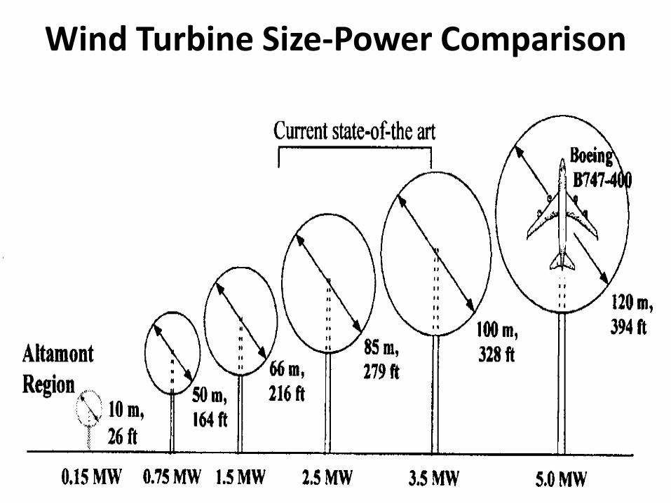
Wind Turbine Size-Power Comparison
Largest Wind Turbine• The Enercon E-126 has a rated capacity of 7.58 MW,
has an overall height of 198 m (650 ft), a diameter of
126 m (413 ft), and is the world's largest-capacity
wind turbine since its introduction in 2007.
• WEGs are operated either at fixed speed or variable
speed.
• Generators driven by fixed speed turbines can be
directly connected to grid.
• Variable speed generators need a power electronic
converter interface for interconnection with the grid.
• Variable speed generation is preferred over fixed
speed generation.
Advantages of variable speed wind turbine
• Better Energy Capture
• Mechanical stress reduction of wind turbine
• Acoustic noise reduction
• Cost effective and entirely feasible
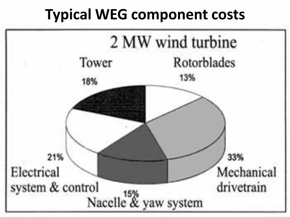
Typical WEG component costs
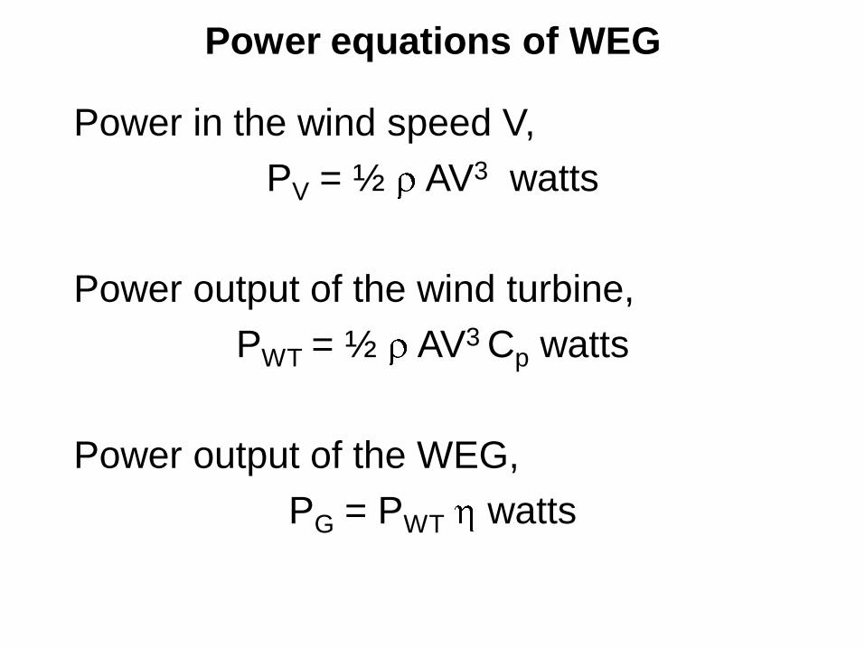
Power equations of WEG
Power in the wind speed V,
PV = ½ AV3 watts
Power output of the wind turbine,
PWT = ½ AV3 Cp watts
Power output of the WEG,
PG = PWT watts
3
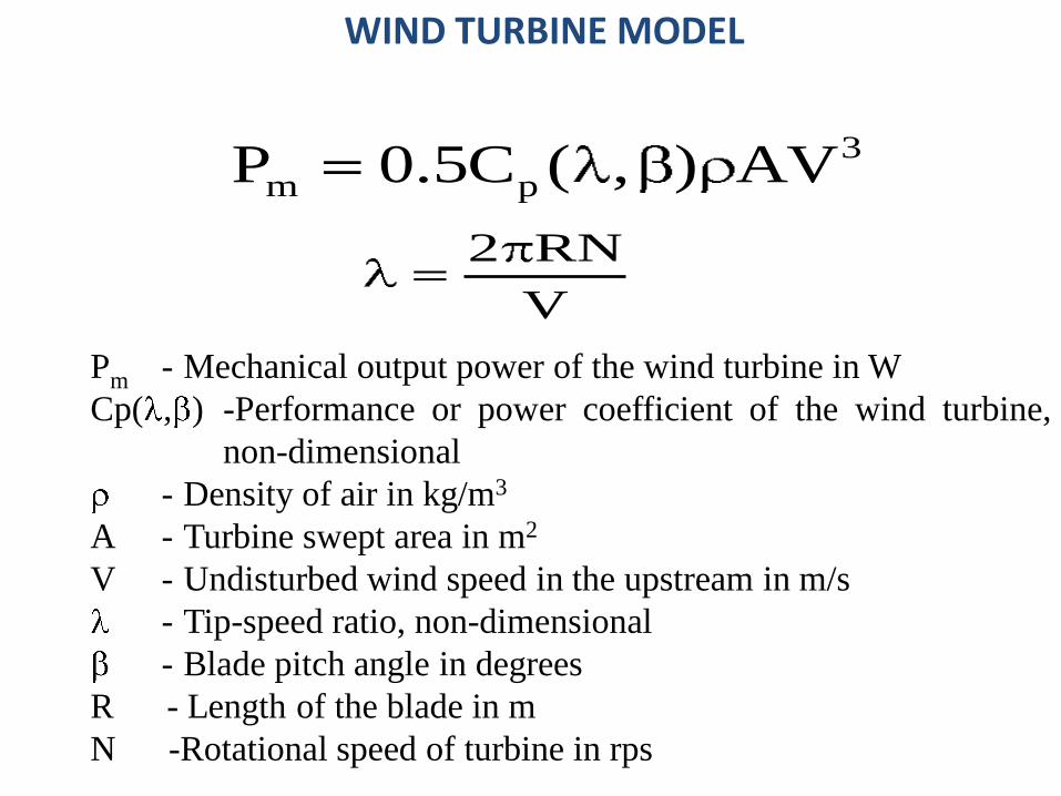
m pP 0.5C ( , ) AV
2 RN
V
Pm - Mechanical output power of the wind turbine in W
Cp( , ) -Performance or power coefficient of the wind turbine,
non-dimensional
- Density of air in kg/m3
A - Turbine swept area in m2
V - Undisturbed wind speed in the upstream in m/s
- Tip-speed ratio, non-dimensional
- Blade pitch angle in degrees
R - Length of the blade in m
N -Rotational speed of turbine in rps
WIND TURBINE MODEL
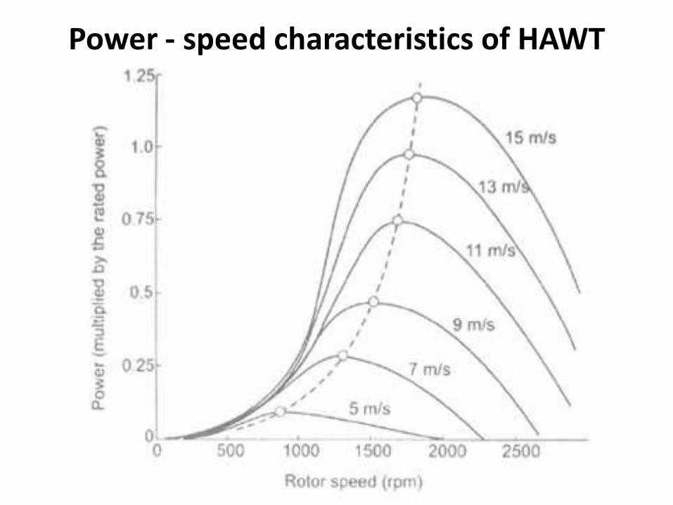
Power - speed characteristics of HAWT
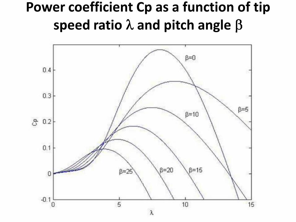
Power coefficient Cp as a function of tip speed ratio and pitch angle
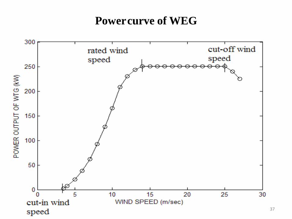
Powercurve of WEG
37
Power curve of WEG
• Below cut-in speed, the machine doesnot produce power due to the lowenergy content of the wind. If the rotorhas a sufficient starting torque, it maystart its rotation below this wind speed.But no power is extracted as the powerin the wind is insufficient to meet thesystem losses. In many modern designs,the aerodynamic torque produced at thestandstill condition is quite low and therotor has to be started by running thegenerator in the motor mode at the cut-in wind speed.
Power curve of WEG
• At normal wind speeds, the maximumavailable power is extracted from thewind. This region corresponds to theportion between cut-in speed and ratedspeed. Over this region, the aerodynamicefficiency will be high. Maximumefficiency is achieved at a specific valueof tip speed ratio. To track the maximumpower point, the rotational speed has tobe changed continuously in proportion tothe wind speed.
Power curve of WEG• At high wind speeds, the rotor speed is limited to
the maximum value depending on the designlimit of the mechanical components; this speedyields a low value of that corresponds to a lowCp which produces only the rated power outputof the turbine even when the power contained bythe wind is much higher. This region correspondsto the portion between rated speed and cut-offspeed or furling wind speed. The aerodynamicefficiency is reduced here to prevent overloadingof the electrical system.
• For wind speeds higher than rated and lowerthan cut-out:– blade pitching or blade stalling is used to
maintain loading within the equipment’s rating
Power curve of WEG
• At the cut-off speed, the turbine is turnedaway from the wind, generator is thendisconnected from the grid and the rotation isstopped by applying brakes in order to protectthe system components. WEGs are shut downto avoid excessive mechanical stress.
Types of WEGs
• As the penetration level of wind energy isincreasing day by day, it is time to look intothe problems faced by WEGs and solve them.
• The WEGs use different types of generatorssuch as Squirrel Cage Induction Generator, SlipRing Induction Generator, Doubly FedInduction Generator and Permanent MagnetSynchronous Generator .
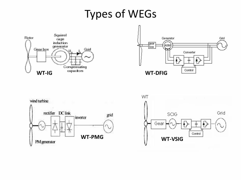
Types of WEGs
WT-IG WT-DFIG
WT-PMG WT-VSIG
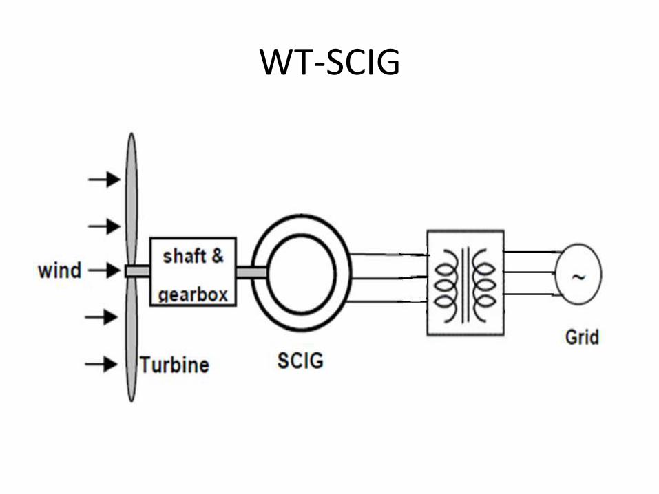
WT-SCIG
WT-SCIG• In normal motor operation, stator flux rotation is
faster than the rotor rotation. This causes the stator flux to induce rotor currents, which create a rotor flux with magnetic polarity opposite to stator. In this way, the rotor is dragged along behind stator flux, at a value equal to the slip.
• In generator operation, the wind turbine drives the rotor above the synchronous speed. The stator flux still induces currents in the rotor, but since the opposing rotor flux is now cutting the stator coils, an active current is produced in stator coils, and the motor now operates as a generator, sending power back to the electrical grid
WT-SCIG• Well known and robust technology, high
efficiency, easy and relatively cheap because ofmass production of the generator.
• Inherent overload protection.
• No use of slip rings and brushes, and thereforealmost maintenance-free.
• synchronous grid connection
• Starts as motor
• stall regulated or pitch-controlled WT
• Reactive power from grid; VAR compensation byshunt capacitors at WEG terminals
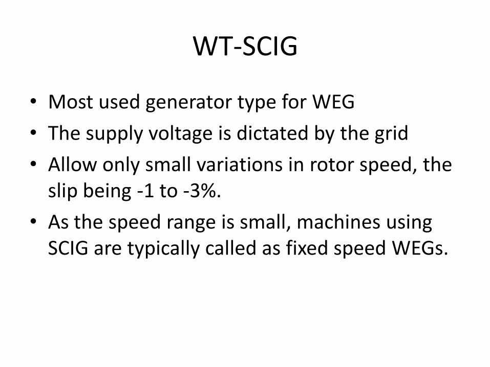
• Most used generator type for WEG
• The supply voltage is dictated by the grid
• Allow only small variations in rotor speed, the slip being -1 to -3%.
• As the speed range is small, machines using SCIG are typically called as fixed speed WEGs.
WT-SCIG
WT-DWIG
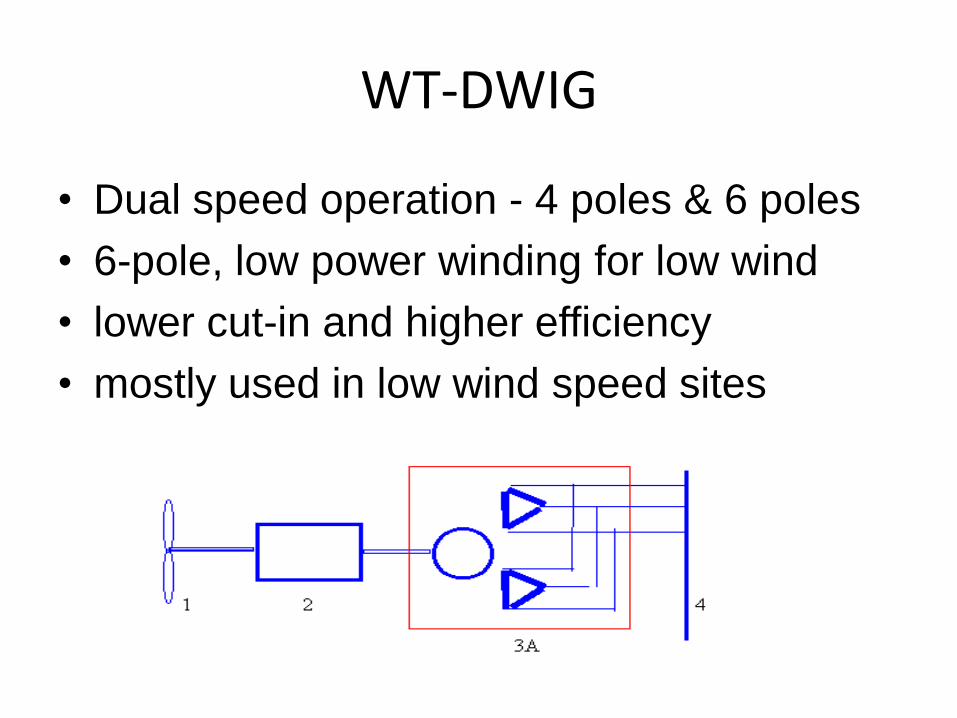
• Dual speed operation - 4 poles & 6 poles
• 6-pole, low power winding for low wind
• lower cut-in and higher efficiency
• mostly used in low wind speed sites
WT-WRIG
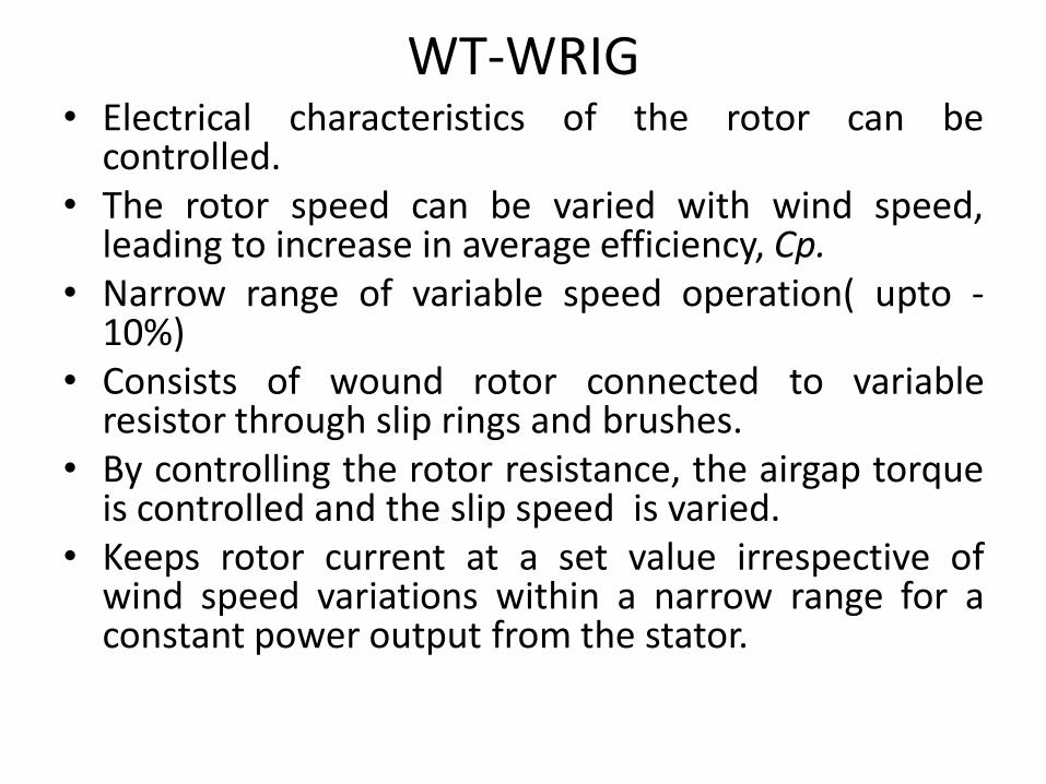
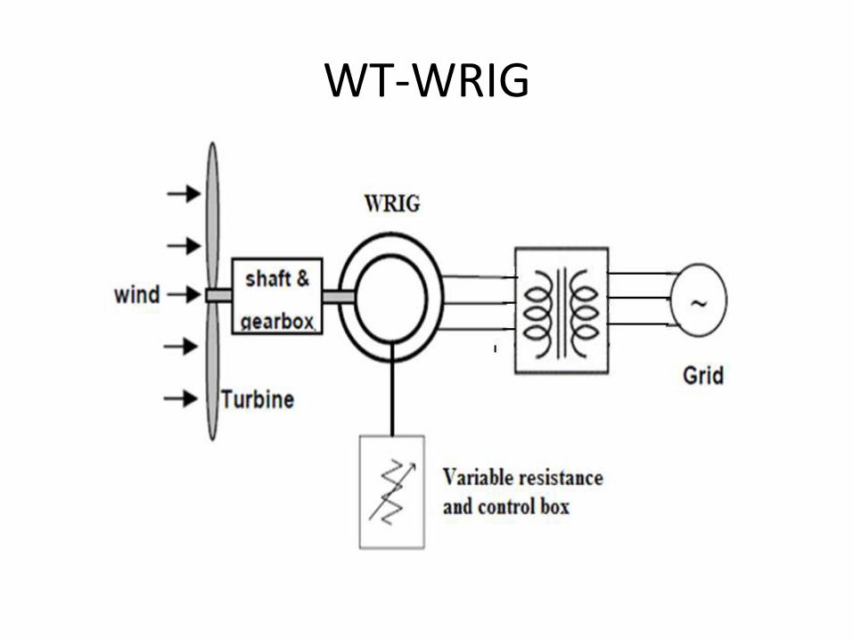
WT-WRIG• Electrical characteristics of the rotor can be
controlled.• The rotor speed can be varied with wind speed,
leading to increase in average efficiency, Cp.• Narrow range of variable speed operation( upto -
10%)• Consists of wound rotor connected to variable
resistor through slip rings and brushes.• By controlling the rotor resistance, the airgap torque
is controlled and the slip speed is varied.• Keeps rotor current at a set value irrespective of
wind speed variations within a narrow range for aconstant power output from the stator.
WT-WRIG
• Power Electronic Converter(PEC) is controllingthe variable external resistance continuouslyby soft starting.
• Not rugged.
• Most power dissipated as heat in the rotor.Less efficiency. For every 1% increase in slip,extra 1% losses occur.
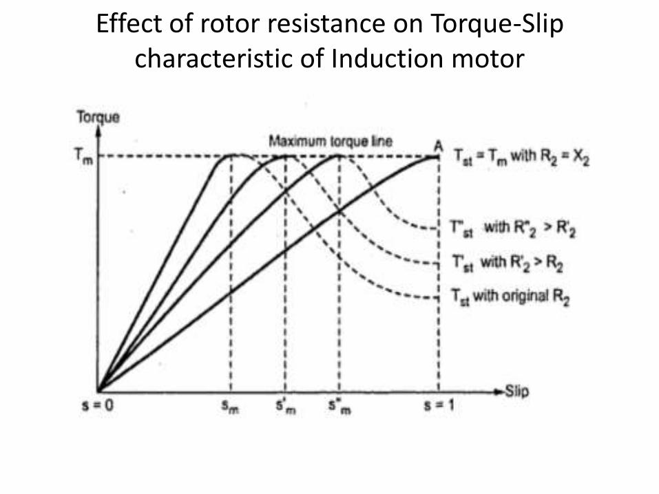
Effect of rotor resistance on Torque-Slip characteristic of Induction motor
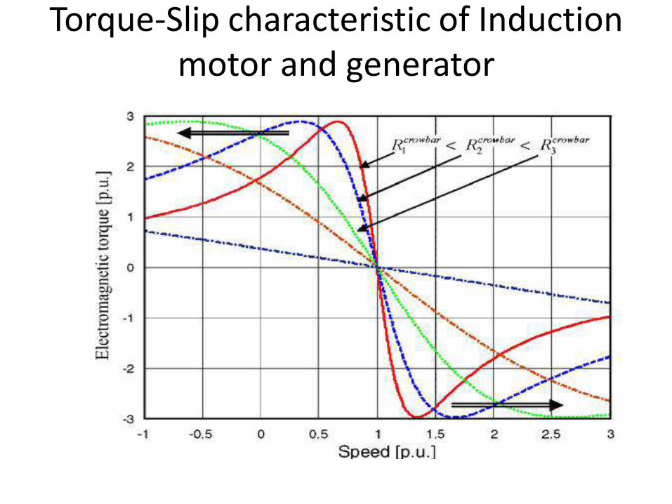
Torque-Slip characteristic of Induction motor and generator
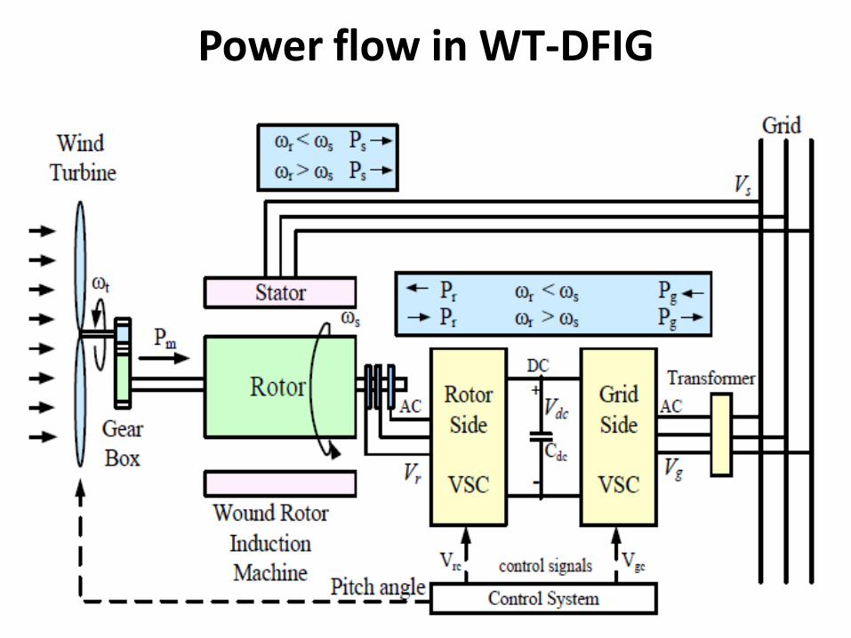
Power flow in WT-DFIG
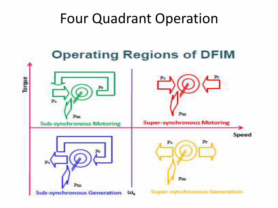
Four Quadrant Operation
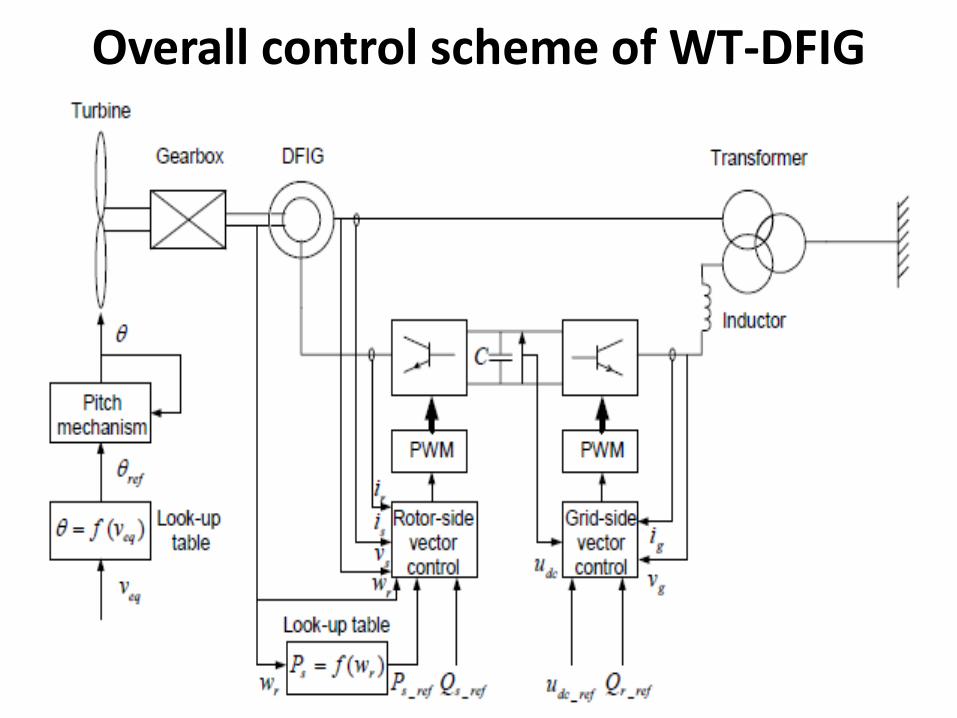
Overall control scheme of WT-DFIG
WT-DFIG
• An induction generator with three phasestator winding connected directly to grid
• Three phase rotor winding connected togrid through partially rated(25%-30%)back to back PEC. So substantial savingin investment cost.
• Power in the rotor circuit is recovered,treated, transformed and sent to grid.
• PEC (IGBT based PWM VSCs) has abidirectional power flow.
WT-DFIG
• Frequency fed to the rotor winding isproportional to slip times the statorfrequency and voltage across the rotorwinding is determined by the statorvoltage, slip and turns ratio of rotor tostator winding.
• Speed range + or – 30 % of synchronousspeed (sub synchronous and supersynchronous speeds)
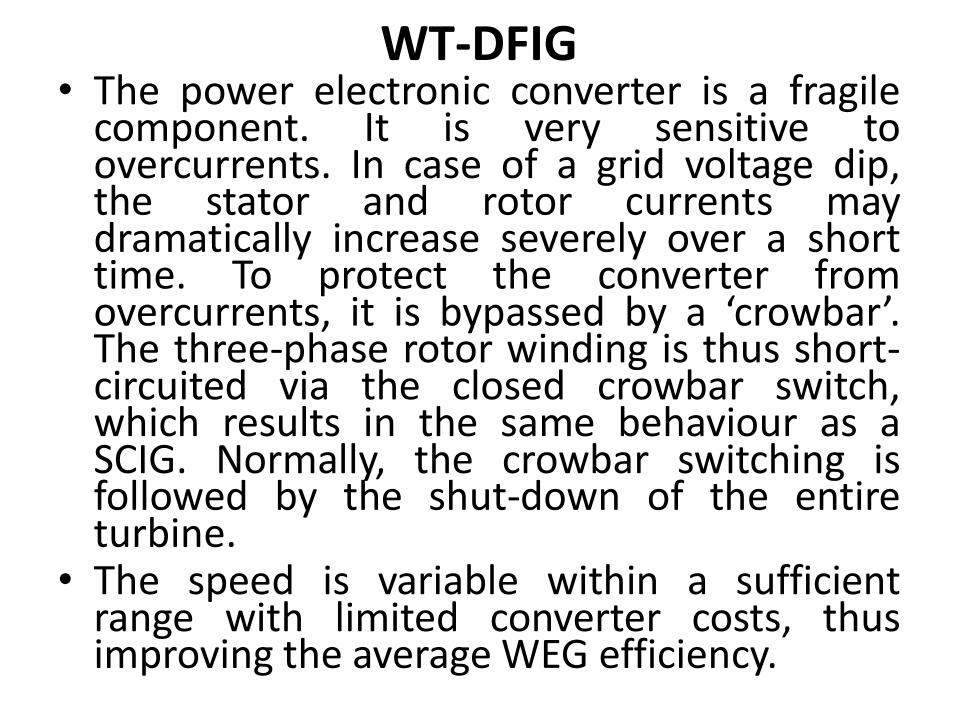
WT-DFIG• The power electronic converter is a fragile
component. It is very sensitive toovercurrents. In case of a grid voltage dip,the stator and rotor currents maydramatically increase severely over a shorttime. To protect the converter fromovercurrents, it is bypassed by a ‘crowbar’.The three-phase rotor winding is thus short-circuited via the closed crowbar switch,which results in the same behaviour as aSCIG. Normally, the crowbar switching isfollowed by the shut-down of the entireturbine.
• The speed is variable within a sufficientrange with limited converter costs, thusimproving the average WEG efficiency.
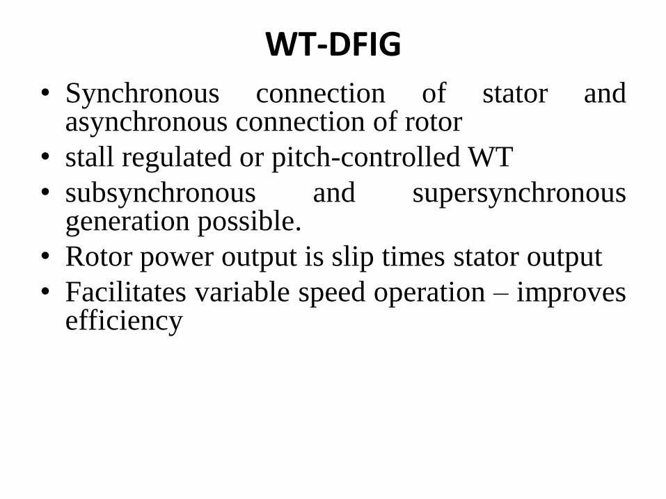
WT-DFIG
• Synchronous connection of stator andasynchronous connection of rotor
• stall regulated or pitch-controlled WT
• subsynchronous and supersynchronousgeneration possible.
• Rotor power output is slip times stator output
• Facilitates variable speed operation – improvesefficiency
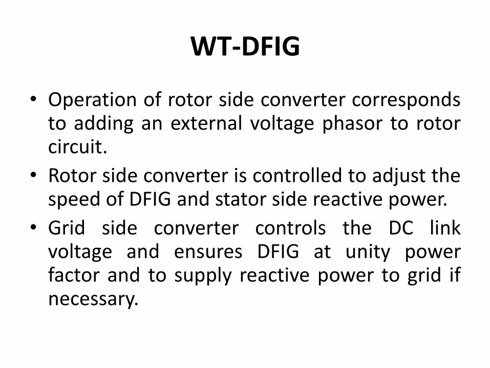
WT-DFIG
• Operation of rotor side converter correspondsto adding an external voltage phasor to rotorcircuit.
• Rotor side converter is controlled to adjust thespeed of DFIG and stator side reactive power.
• Grid side converter controls the DC linkvoltage and ensures DFIG at unity powerfactor and to supply reactive power to grid ifnecessary.
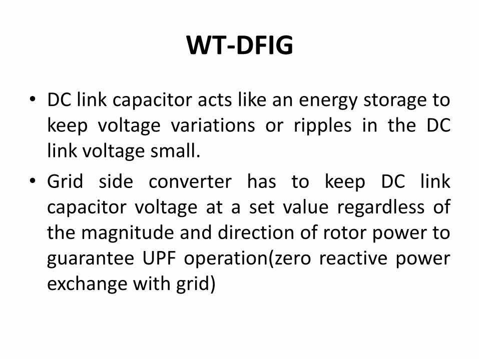
WT-DFIG
• DC link capacitor acts like an energy storage tokeep voltage variations or ripples in the DClink voltage small.
• Grid side converter has to keep DC linkcapacitor voltage at a set value regardless ofthe magnitude and direction of rotor power toguarantee UPF operation(zero reactive powerexchange with grid)
WT-DFIG
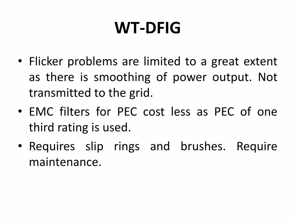
• Flicker problems are limited to a great extentas there is smoothing of power output. Nottransmitted to the grid.
• EMC filters for PEC cost less as PEC of onethird rating is used.
• Requires slip rings and brushes. Requiremaintenance.
WT-PMSG
WT-PMSG
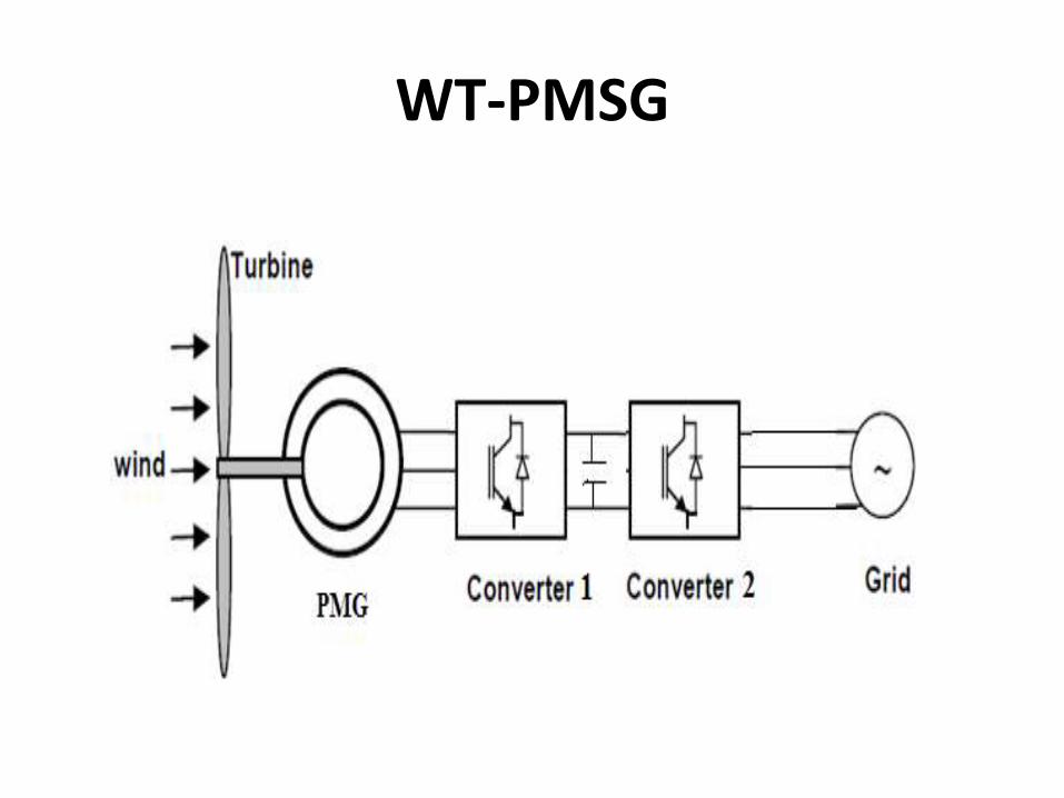
• Permanent Magnet Generator is another typeof generator employed to solve the dilemmasof fixed speed and variable reactive powercharacteristics of induction generator. This isthe synchronous type of machine, which issame as used in a traditional power plant. Themachine generates electrical power at afrequency directly related to the shaft speed. Inorder to achieve variable speeds, the output ofthe synchronous generator is asynchronouslyconnected to the grid via back to backconverters.
WT-PMSG
• Due to the advancement of permanent magnettechnology, large wind plants use PMSG.
• Absence of windings in the generator rotor.
• Gear box avoided as large number of poles forlow operating speed is used.
• Multipole-large diameter
• Self excited
• No need of slip rings and brushes.
WT-PMSG
• PM rotor has surface mounted permanentmagnets, capable of producing a larger airgap fluxdensity.
• High energy producers,high power to weight ratioand very short axial length to form compact WEG.
• External rotor type and Internal rotor type
• As permanent magnets are temperaturesensitive, elaborate cooling arrangement isprovided.
WT-PMSG
• Rotor side converter controls the rotor speed andthus the power by means of generator current. Italso regulates the electromagnetic torque tooptimise the aerodynamic efficiency of the windturbine enabling MPPT for maximising energycapture from wind.
• Grid side converter maintains reactive powerexchange between grid and WEG by keeping theDC link voltage constant.
• Danger of demagnetisaion of magnets.
WT-PMSG
• The converter costs are considerable, as it hasto process all the generator power. Thisrequires expensive power electroniccomponents and intensive cooling.
• The generator needs a specific designcompared to normal electrical machines. Ithas to supply high electrical torque at lowspeeds, which requires a large rotor .
• The converter losses are higher compared toDFIG as the entire power transfer is through it.
• The strength of permanent magnets maydeteriorate over a period of time.
WT-PMSG
• Gearbox is no longer required. This isadvantageous because this componentnormally has a non-negligible manufacturingcost, generates some acoustic noise, requiresregular maintenance (lubrication) and is also apotential cause of mechanical failure.
• The converter permits very flexible control ofthe entire system. Speed, active and reactivepower can be fully controlled in case ofnormal and disturbed grid conditions. Ofcourse, in highly disturbed grid conditions, thegenerator still has to be disconnected forsafety reasons.
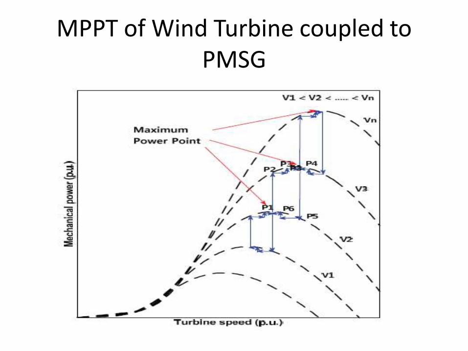
MPPT of Wind Turbine coupled to PMSG
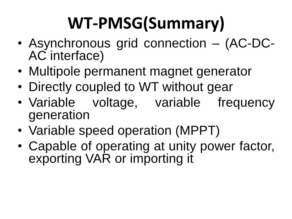
WT-PMSG(Summary)• Asynchronous grid connection – (AC-DC-
AC interface)
• Multipole permanent magnet generator
• Directly coupled to WT without gear
• Variable voltage, variable frequencygeneration
• Variable speed operation (MPPT)
• Capable of operating at unity power factor,exporting VAR or importing it
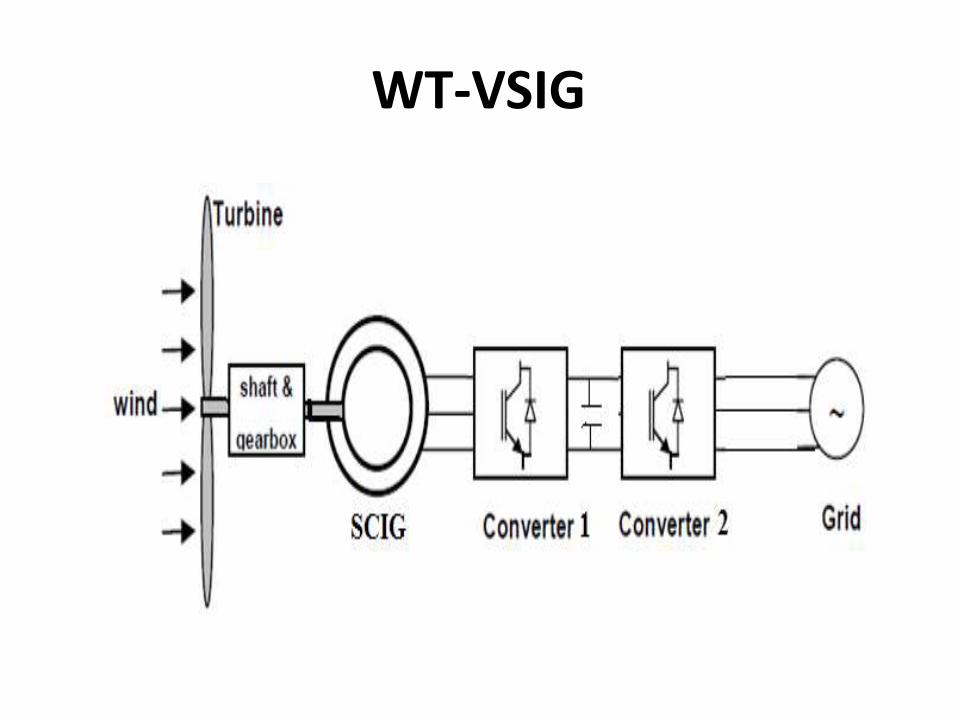
WT-VSIG
WT-VSIG
• The disadvantages of fixed speed inductiongenerator such as narrow range of speedvariation and consumption of reactive powerare overcome by using back to backconverters between the grid and the SCIG. Butthe drawback is full rating converters areneeded for interfacing with the grid, whichwill increase its cost besides causing a powerloss in the converters.
WT-VSIG
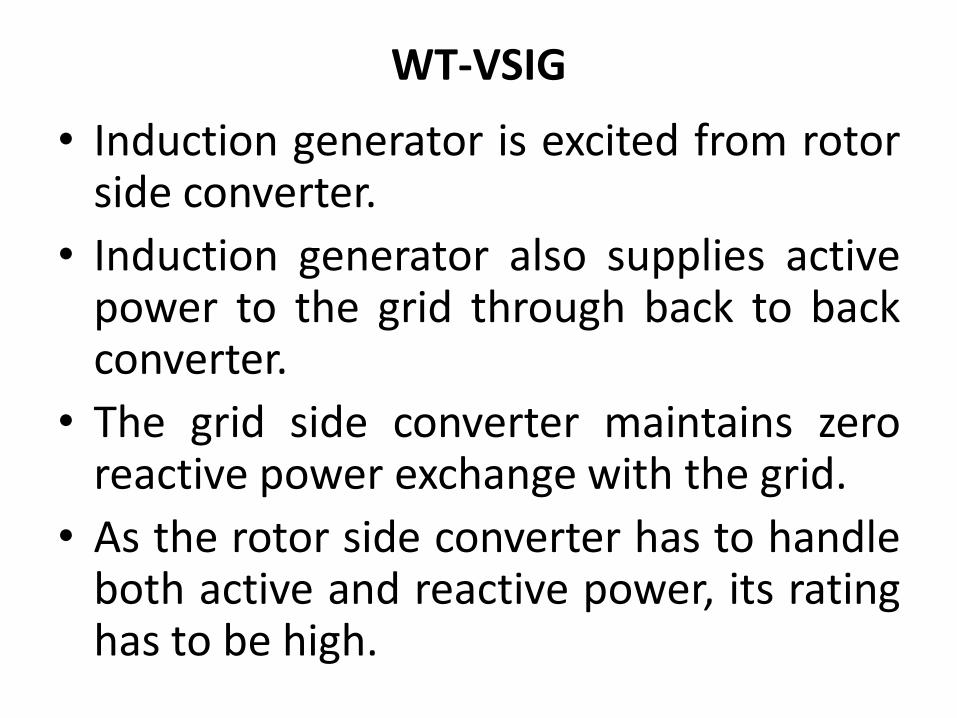
• Induction generator is excited from rotorside converter.
• Induction generator also supplies activepower to the grid through back to backconverter.
• The grid side converter maintains zeroreactive power exchange with the grid.
• As the rotor side converter has to handleboth active and reactive power, its ratinghas to be high.
WT-VSIG
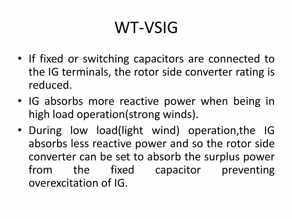
• If fixed or switching capacitors are connected tothe IG terminals, the rotor side converter rating isreduced.
• IG absorbs more reactive power when being inhigh load operation(strong winds).
• During low load(light wind) operation,the IGabsorbs less reactive power and so the rotor sideconverter can be set to absorb the surplus powerfrom the fixed capacitor preventingoverexcitation of IG.
Impacts of windfarms on power quality
• The term "power quality" refers to thevoltage stability, frequency stability, andthe absence of various forms of electricalnoise (e.g. flicker or harmonic distortion)on the electrical grid.
• More broadly speaking, powercompanies (and their customers) preferan alternating current with a nicesinusoidal shape.
Power quality
• Voltage variations
• Voltage flicker
• Harmonics
• Reactive power compensation (FACTS devices)
• Stability support
• Frequency and power control (Energy storage)
Power quality issues
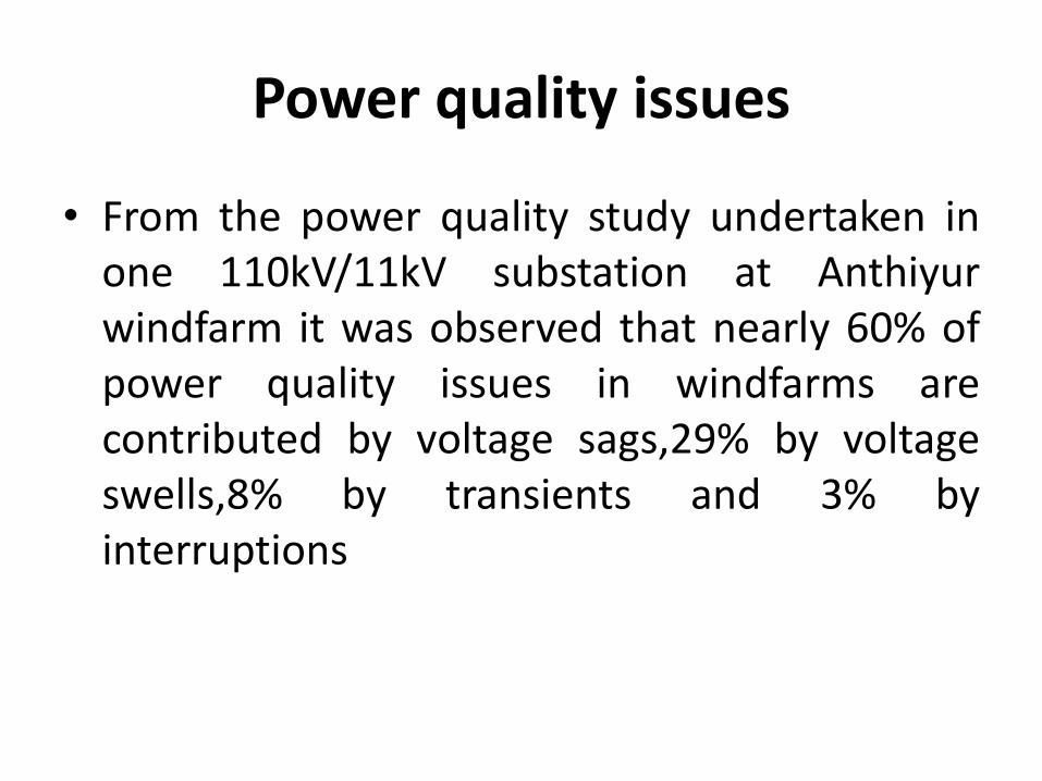
• From the power quality study undertaken inone 110kV/11kV substation at Anthiyurwindfarm it was observed that nearly 60% ofpower quality issues in windfarms arecontributed by voltage sags,29% by voltageswells,8% by transients and 3% byinterruptions
Indian Electricity Grid Code(IEGC)
• The grid code is a technical document containingthe rules that govern the operation, developmentand use of the transmission system. With theincreasing level of wind electric penetration, thegrid codes need to be adjusted. With the changeson the grid codes regarding the increasingpenetration of new generation technologies, thegrid operators intend to avoid those actions whichmay cause the power system operation to be in arisk under certain conditions. Therefore, the overallamount of wind power to be injected into theelectrical system in the future can only be increasedwith an improved compliance with the wind gridcodes.
Indian Electricity Grid Code
• Central Electricity Regulatory Commission, New Delhi approved Indian Wind Grid Code. Dated 28th April 2010
• It lays down rules, guide lines and standards to be followed in planning, development maintaining and operation, so that security reliability and economics are not compromised.
• Part 6 of IEGC include Scheduling and Dispatch code
–wind and solar included
Scheduling & Forecasting
• Scheduling is required for wind farms of installed capacity10 MW and above and connected to 33kV or higher
• For capacity less than 10MW and voltage less than 33kVand old wind farms - to be mutually decided between WFand EB
• Forecasting of wind power generation with 70% accuracy isrequired
• If generation is below the scheduled value, UnscheduledInterchange (UI) charges will be applicable
• Generation above 150% of the schedule will not be allowed
Contents of IWGC
Indian Wind Grid Code (IWGC) gives guidelines fortransmission planning, grid connection and operationof windfarms.
(i) Role of various organisations and their linkagesNLDC,RLDC,RPC,CTU,CEA,DLDC,STU etc.
(ii)Planning code for transmission systems evacuatingwind power
(iii) Connection Code for windfarms
(iv) Operating code for windfarms
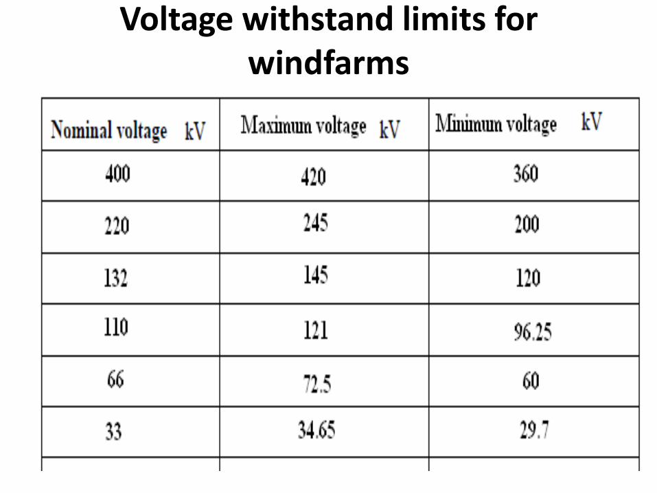
Voltage withstand limits for windfarms
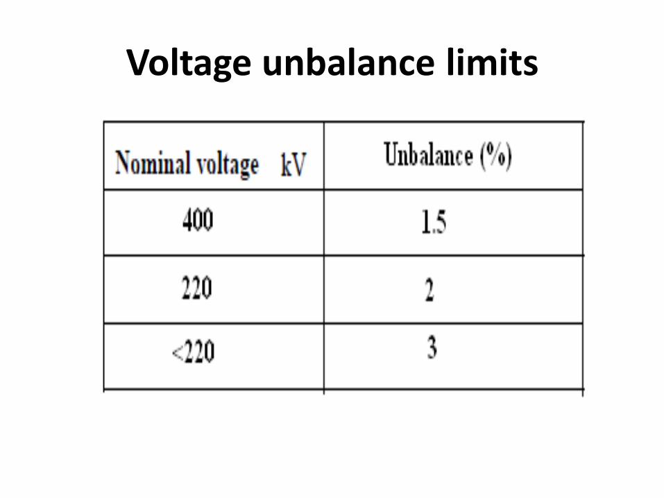
Voltage unbalance limits
Tolerance limits
• Frequency range 47.5Hz to 51.5kHz
• Rate of change of frequency is 0.5Hz/sec
• Windfarms connected at 66kV andbelow shall maintain power factorbetween 0.95 lagging and 0.95 leadingat PCC(Reactive power capability)
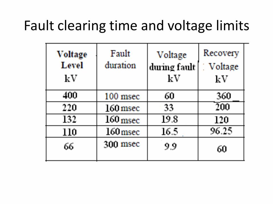
Fault clearing time and voltage limits
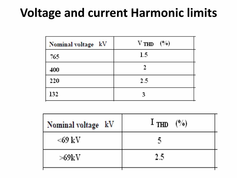
Voltage and current Harmonic limits
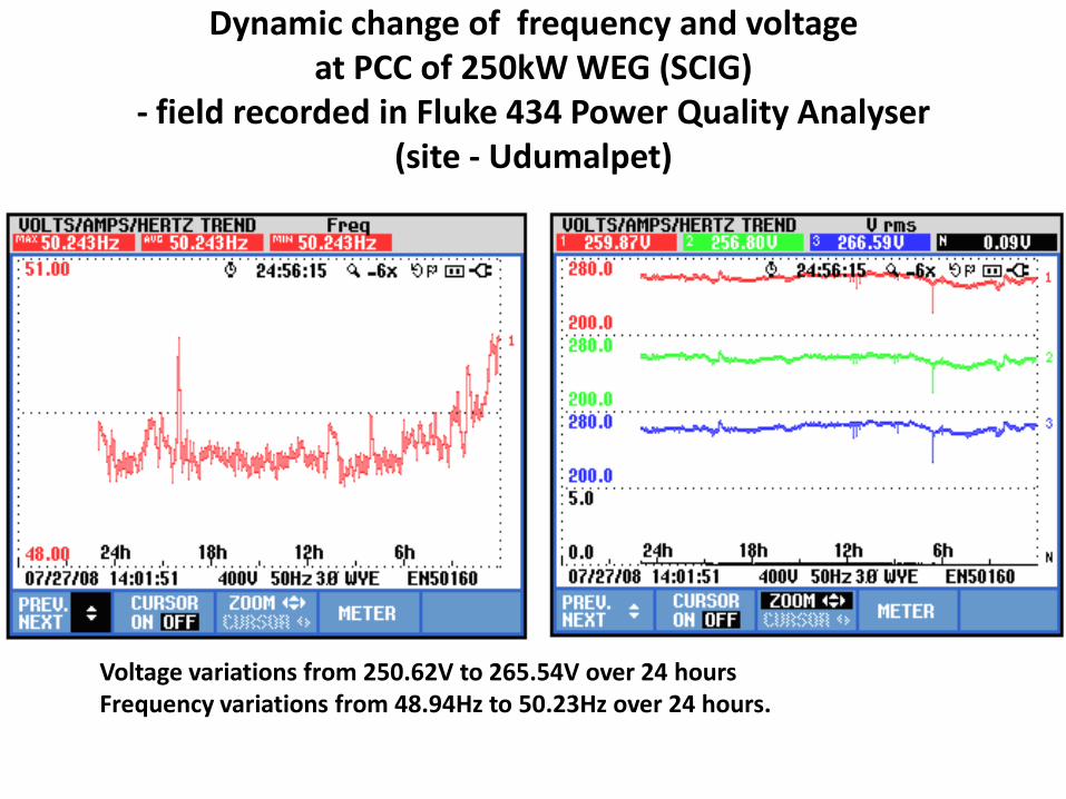
Dynamic change of frequency and voltage at PCC of 250kW WEG (SCIG)
- field recorded in Fluke 434 Power Quality Analyser (site - Udumalpet)
Voltage variations from 250.62V to 265.54V over 24 hoursFrequency variations from 48.94Hz to 50.23Hz over 24 hours.
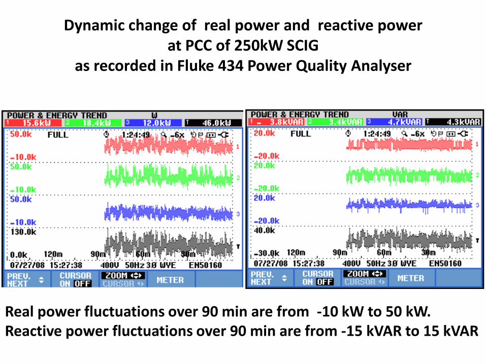
Dynamic change of real power and reactive power at PCC of 250kW SCIG
as recorded in Fluke 434 Power Quality Analyser
Real power fluctuations over 90 min are from -10 kW to 50 kW. Reactive power fluctuations over 90 min are from -15 kVAR to 15 kVAR
FRT capability of WEG
• Means the wind turbine should remainconnected to the grid during the fault withoutgetting tripped. Problem is more severe inSCIG based windfarm.
• Windfarms using SCIG directly connected tothe grid would be disconnected from thepower system when the grid voltage dropsmore than 30% below the rated value.
• The requirement of FRT capability can affectthe economics of smaller windfarms in thepresent scenario.
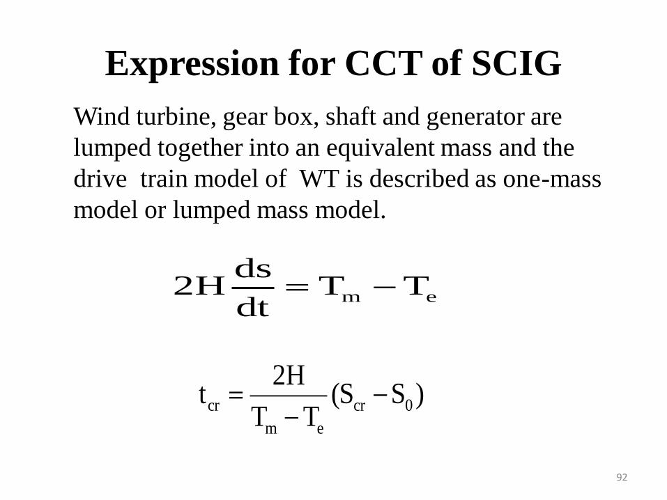
Expression for CCT of SCIG
m e
ds2H T T
dt
cr cr 0
m e
2Ht (S S )
T T
Wind turbine, gear box, shaft and generator are
lumped together into an equivalent mass and the
drive train model of WT is described as one-mass
model or lumped mass model.
92
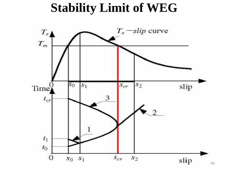
Stability Limit of WEG
93
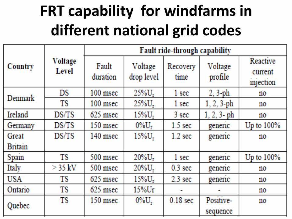
FRT capability for windfarms in different national grid codes
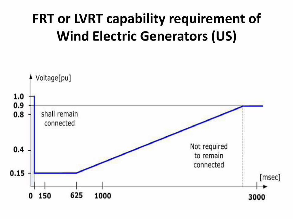
FRT or LVRT capability requirement of Wind Electric Generators (US)
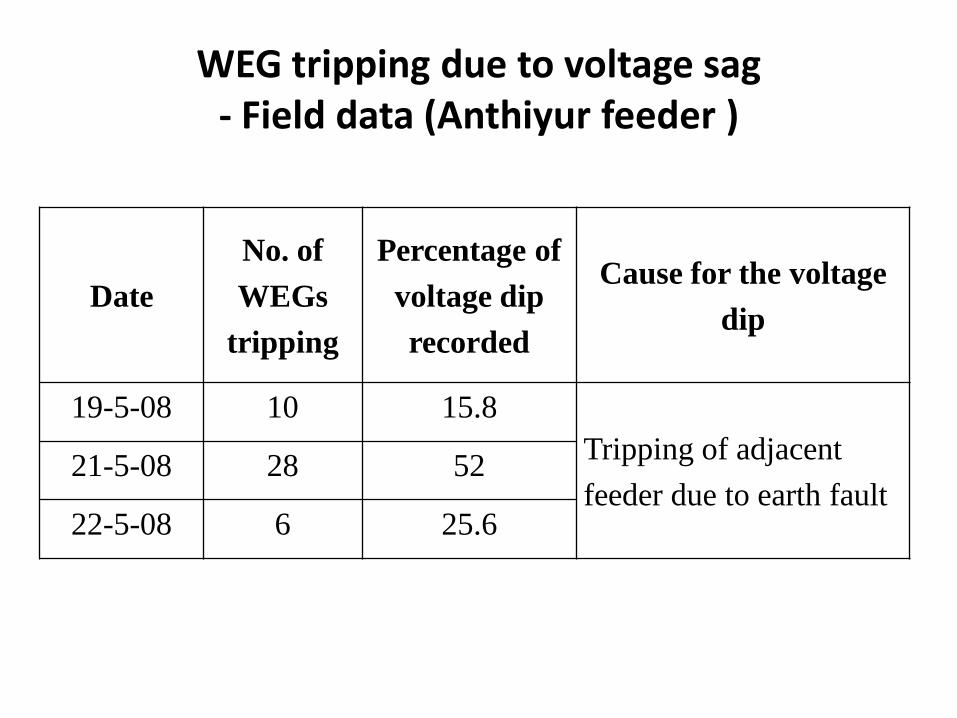
WEG tripping due to voltage sag - Field data (Anthiyur feeder )
Date
No. of
WEGs
tripping
Percentage of
voltage dip
recorded
Cause for the voltage
dip
19-5-08 10 15.8
Tripping of adjacent
feeder due to earth fault21-5-08 28 52
22-5-08 6 25.6
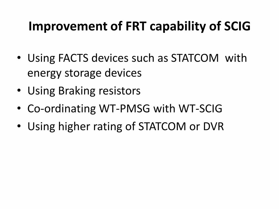
Improvement of FRT capability of SCIG
• Using FACTS devices such as STATCOM with energy storage devices
• Using Braking resistors
• Co-ordinating WT-PMSG with WT-SCIG
• Using higher rating of STATCOM or DVR
Methods for improving grid fault ride through capability of PMSG
• In case of grid fault, the excess powerproduced by generator can be controlled bymeans of chopper circuit that maintain the DClink voltage constant.
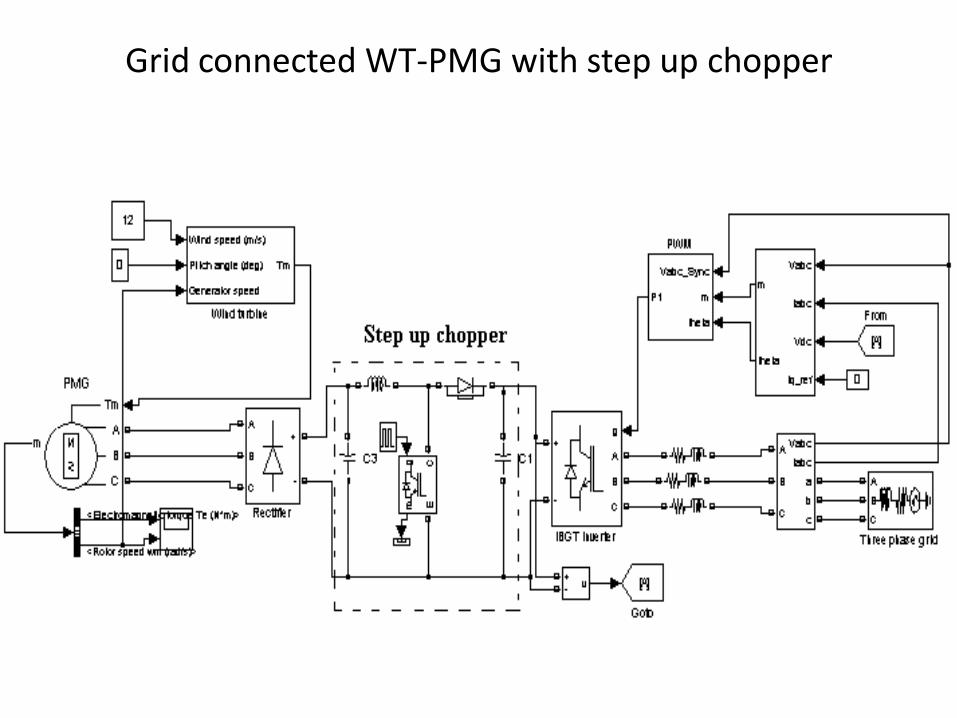
Grid connected WT-PMG with step up chopper
Methods for improving grid fault ride through capability of DFIG
• Active crowbar circuits: When crowbar is triggered ,the rotor side converter is disabled and bypassed. Soindependent control of P and Q gets lost and acts likeSCIG.
• Antiparallel thyristors in the rotor circuit to achievequick disconnection within 10ms and then toremagnetise DFIG and reconnect the stator as quicklyas possible.
• Dynamic Voltage Restorer• Higher rating of Power Electronic Converters• Choice depends on their dynamic performance, their
relative efficiency and cost.

THANK YOU