wincc v7.0 gettingstarted en-us
TRANSCRIPT

SIMATIC WinCC V7.0 Getting started ______________________________________________________________________________________________________________________________
Getting started 1
Welcome 2
Icons 3
Creating a project 4
Configure communication 5
Configuring the Process Screens
6Archiving and displaying values
7Outputting values from the process archive
8
Configuring messages 9
SIMATIC
WinCC V7.0 Getting started
Printout of the Online Help
04/2008 A5E02211557-01

Safety Guidelines Safety Guidelines This manual contains notices you have to observe in order to ensure your personal safety, as well as to prevent damage to property. The notices referring to your personal safety are highlighted in the manual by a safety alert symbol, notices referring only to property damage have no safety alert symbol. These notices shown below are graded according to the degree of danger.
DANGER indicates that death or severe personal injury will result if proper precautions are not taken.
WARNING indicates that death or severe personal injury may result if proper precautions are not taken.
CAUTION with a safety alert symbol, indicates that minor personal injury can result if proper precautions are not taken.
CAUTION without a safety alert symbol, indicates that property damage can result if proper precautions are not taken.
NOTICE indicates that an unintended result or situation can occur if the corresponding information is not taken into account.
If more than one degree of danger is present, the warning notice representing the highest degree of danger will be used. A notice warning of injury to persons with a safety alert symbol may also include a warning relating to property damage.
Qualified Personnel The device/system may only be set up and used in conjunction with this documentation. Commissioning and operation of a device/system may only be performed by qualified personnel. Within the context of the safety notes in this documentation qualified persons are defined as persons who are authorized to commission, ground and label devices, systems and circuits in accordance with established safety practices and standards.
Prescribed Usage Note the following:
WARNING This device may only be used for the applications described in the catalog or the technical description and only in connection with devices or components from other manufacturers which have been approved or recommended by Siemens. Correct, reliable operation of the product requires proper transport, storage, positioning and assembly as well as careful operation and maintenance.
Trademarks All names identified by ® are registered trademarks of the Siemens AG. The remaining trademarks in this publication may be trademarks whose use by third parties for their own purposes could violate the rights of the owner.
Disclaimer of Liability We have reviewed the contents of this publication to ensure consistency with the hardware and software described. Since variance cannot be precluded entirely, we cannot guarantee full consistency. However, the information in this publication is reviewed regularly and any necessary corrections are included in subsequent editions.
Siemens AG Industry Sector Postfach 48 48 90327 NÜRNBERG GERMANY
Printout of the Online Help Ⓟ 05/2008
Copyright © Siemens AG 2008. Technical data subject to change

Getting started 04/2008, Printout of the Online Help 3
Table of contents 1 Getting started ........................................................................................................................................... 7 2 Welcome.................................................................................................................................................... 9 3 Icons........................................................................................................................................................ 11 4 Creating a project .................................................................................................................................... 13
4.1 Creating a project.........................................................................................................................13 4.2 Working with WinCC ....................................................................................................................13 4.3 Creating the "Quick_Start" project ...............................................................................................15
5 Configure communication ........................................................................................................................ 19 5.1 Configure communication ............................................................................................................19 5.2 Check the channels and connections in WinCC..........................................................................20 5.3 Tags in WinCC.............................................................................................................................21 5.4 Adding a Channel ........................................................................................................................22 5.5 Creating connections ...................................................................................................................25 5.6 Creating tag group .......................................................................................................................28 5.7 Creating a process tag.................................................................................................................30 5.8 Scaling process tags in WinCC....................................................................................................36 5.9 Creating Internal Tags .................................................................................................................39
6 Configuring the Process Screens ............................................................................................................ 43 6.1 Configuring the Process Screens ................................................................................................43 6.2 The Graphics System ..................................................................................................................44 6.3 Creating process screens ............................................................................................................45 6.4 Editing Process Screens..............................................................................................................47 6.4.1 Editing Process Screens..............................................................................................................47 6.4.2 Inserting graphic objects from the library.....................................................................................48 6.4.3 Inserting "Static text" ....................................................................................................................55 6.4.4 Editing the process screen "SAMPLE.pdl" ..................................................................................57 6.5 Using customized menus and toolbars........................................................................................59 6.5.1 Using customized menus and toolbars........................................................................................59 6.5.2 Creating procedures for customized menus and toolbars ...........................................................60 6.5.3 Creating a customized menu for screen changes .......................................................................66 6.5.4 Creating a customized toolbar to exit Runtime ............................................................................71

Table of contents
Getting started 4 04/2008, Printout of the Online Help
6.6 Process picture dynamics ........................................................................................................... 77 6.6.1 Process picture dynamics ........................................................................................................... 77 6.6.2 Making the fill level indicator dynamic......................................................................................... 78 6.6.3 Inserting an I/O Field and Making it Dynamic ............................................................................. 82 6.7 Defining the Runtime Properties ................................................................................................. 87 6.8 Activating the project................................................................................................................... 91 6.9 Test project ................................................................................................................................. 93 6.10 Deactivating a project.................................................................................................................. 96
7 Archiving and displaying values............................................................................................................... 97 7.1 Archiving and displaying values.................................................................................................. 97 7.2 The archive system..................................................................................................................... 97 7.3 Starting Tag Logging................................................................................................................. 100 7.4 Configuring Timers.................................................................................................................... 101 7.5 Creating Process Value Archive ............................................................................................... 104 7.6 Editing the process value archive ............................................................................................. 108 7.7 Configuring the Process Screen ............................................................................................... 113 7.7.1 Configuring the Process Screen ............................................................................................... 113 7.7.2 Configuring a trend window....................................................................................................... 114 7.7.3 Configuring a table window....................................................................................................... 122 7.8 Modifying a customized menu for screen changes................................................................... 127 7.9 Defining the Runtime Properties ............................................................................................... 131 7.10 Activating and testing the project .............................................................................................. 134
8 Outputting values from the process archive........................................................................................... 139 8.1 The message report system...................................................................................................... 139 8.2 Outputting values from the process archive.............................................................................. 141 8.3 Creating a Page Layout ............................................................................................................ 141 8.4 Editing the Page Layout ............................................................................................................ 144 8.4.1 Editing the Page Layout ............................................................................................................ 144 8.4.2 Establishing properties of the page layout ................................................................................ 146 8.4.3 Determine log content ............................................................................................................... 150 8.4.4 Editing the header ..................................................................................................................... 154 8.4.5 Editing the footer ....................................................................................................................... 158 8.5 Editing the print job ................................................................................................................... 161 8.5.1 Editing the print job ................................................................................................................... 161 8.5.2 Defining and editing the Print Job ............................................................................................. 161 8.6 Defining the Runtime Properties ............................................................................................... 166 8.7 Activating and testing the project .............................................................................................. 167 8.8 Printing log ................................................................................................................................ 171
Table of contents
Getting started 04/2008, Printout of the Online Help 5
9 Configuring messages ........................................................................................................................... 175 9.1 Configuring messages ...............................................................................................................175 9.2 The message system enables the following: .............................................................................176 9.3 Start alarm logging.....................................................................................................................178 9.4 Setting message blocks and message classes .........................................................................179 9.5 Changing the length of the user text blocks...............................................................................183 9.6 Configuring bit messages ..........................................................................................................185 9.6.1 Configuring bit messages ..........................................................................................................185 9.6.2 Creating bit messages ...............................................................................................................185 9.6.3 Editing bit messages..................................................................................................................187 9.7 Configuring analog messages ...................................................................................................192 9.7.1 Configuring analog messages ...................................................................................................192 9.7.2 Integrating limit value monitoring ...............................................................................................192 9.7.3 Setting Limit Values ...................................................................................................................195 9.8 Define color of the message statuses........................................................................................200 9.9 Configuring the Process Screen ................................................................................................202 9.9.1 Configuring the Process Screen ................................................................................................202 9.9.2 Configuring an Alarm Message Window....................................................................................203 9.9.3 Inserting a slider object and making it dynamic .........................................................................207 9.9.4 Inserting a scale.........................................................................................................................212 9.9.5 Inserting an I/O Field and Making it Dynamic ............................................................................216 9.10 Adapting the User-defined Menu for a Picture Change.............................................................222 9.11 Defining the Runtime Properties................................................................................................226 9.12 Activate the project ....................................................................................................................228 9.13 Test project ................................................................................................................................230
Glossary ................................................................................................................................................ 237 Index...................................................................................................................................................... 245

Table of contents
Getting started 6 04/2008, Printout of the Online Help

Getting started 04/2008, Printout of the Online Help 7
Getting started 1Contents
This Getting Started provides a quick and precise introduction to WinCC Version 7. It does not contain a comprehensive list of all possible functions, but includes all necessary information to use WinCC's main features.

Getting started
Getting started 8 Getting Started, 04/2008, Printout of the Online Help

Getting started 04/2008, Printout of the Online Help 9
Welcome 2Welcome to WinCC Getting Started. Getting Started uses an sample project to show you how easy it is to work with WinCC. You will need less than 4 hours to work through all subjects of this documentation and to learn the basics of WinCC configuration. The extent of the documentation is based on the picture display of the different configuration steps. WinCC is a powerful HMI system for use under Microsoft Windows XP, Windows Vista and Microsoft Windows Server 2003. HMI stands for "Human Machine Interface", i.e. the interface between the person and the machine. WinCC allows the operation and observance of the processes that run in a machine. The communication between WinCC and the machine takes place via an automation system.
The creation of a sample project is described in Getting Started. You will control a water supply system with this project. For this, you will "configure" different objects that are necessary to operate and monitor the system, such as: ● Screens to depict and operate the processes on the control device. ● Tags to transfer data between the operating device and the installation ● Archive to store the process data ● Alarms to indicate the operating status of the system on the operating device

Welcome
Getting started 10 04/2008, Printout of the Online Help
Getting Started consists of the following chapters: ● Create a project ● Configuring communication ● Configuring the Process Screens ● Archiving and displaying values ● Outputting values from the process archive ● Configuring messages ● Outputting a message report There is a detailed installation guide on the enclosed WinCC DVD. This DVD also includes all programs that you will need to execute the configuration steps.
See also Configuring messages (Page 175) Outputting values from the process archive (Page 141) Archiving and displaying values (Page 97) Configuring the Process Screens (Page 43) Configure communication (Page 19) Creating a project (Page 13)

Getting started 04/2008, Printout of the Online Help 11
Icons 3Introduction
This chapter provides information for the symbols that are used in Getting Started.
Used symbols In order to be able to display the different instruction steps in pictures, the following symbols were used when creating this documentation:
Icon Significance
A click with the left mouse button
A click with the right mouse button
A double-click with the left mouse button
Entering text via the keyboard
Press and hold the left-hand mouse button
Releasing the left mouse button
Dragging with the left mouse button pressed
Numbering of the individual action steps

Icons
Getting started 12 Getting Started, 04/2008, Printout of the Online Help

Getting started 04/2008, Printout of the Online Help 13
Creating a project 44.1 Creating a project
Introduction This chapter provides information about WinCC and a description of how to create a project in WinCC Explorer. The project is the basis for the configuration of a user interface in WinCC. Within the project you will create and edit all objects that you will need to operate and observe the processes.
General procedure The project will be created in WinCC Explorer. The WinCC Explorer is the configuration component of WinCC. You will use this component to manage your projects.
4.2 Working with WinCC
Introduction WinCC is a modular system. WinCC is used to visualize the process and configure a graphic user interface. You will use the user interface to operate and observe the process. WinCC offers the following possibilities: ● WinCC allows you to observe the process. The process is displayed graphically on the
screen. The display is updated each time a status in the process changes. ● WinCC allows you to operate the process. For example, you can indicate a setpoint from
the user interface or you can open a valve. ● WinCC allows you to monitor the process. An alarm will automatically signal in the event
of a critical process status. If, for example, a predefined value is exceeded, a message will appear on the screen.
● WinCC allows you to archive the process. When working with WinCC, process values can either be printed or electronically archived. This facilitates the documentation of the process and allows subsequent access to past production data.
Creating a project 4.2 Working with WinCC
Getting started 14 04/2008, Printout of the Online Help
Components of WinCC Its basic components are the Configuration Software (CS) and Runtime Software (RT) ● WinCC Explorer forms the core of the Configuration software. The entire project structure
is displayed in WinCC Explorer. The project is also administered here. You can retrieve different editors from the WinCC Explorer. Each editor belongs to a certain partial system of WinCC. The most important partial systems of WinCC are:
process unit Editor Function Graphics System Graphics Designer Configuring Screens Signaling system Alarm Logging Configuring messages Archiving system Tag Logging Archiving data Report system Report Designer Create layouts User Administration User Administrator Administering users and user rights Communication Tag management Configure communication
● You execute the project in process mode in WinCC Runtime. The project will then be in Runtime. WinCC Runtime allows the operation and observation of the processes. WinCC Runtime has the following specific tasks: – Reading the configuration data that has been saved in the CS database – Displaying screens on the monitor – It communicates with the automation systems – Archiving current Runtime data, e.g. process values and message events – Controlling the process, e.g. through setpoint input or switching ON and OFF

Creating a project 4.3 Creating the "Quick_Start" project
Getting started 04/2008, Printout of the Online Help 15
4.3 Creating the "Quick_Start" project
Introduction The following steps will show you how to start WinCC and create the "Quick_Start" project. You will create the "Quick_Start" project as a "Single-user project". A "Single-user project" only runs on one computer. Other computers cannot access this project. The project runs on a computer that serves as the server for data processing and as an operating station.
Requirement WinCC V7 is installed.
Procedure 1. Start WinCC:
When you start WinCC for the first time, the "WinCC Explorer" will open. In this dialog, you will select a project type or open an existing project. The next time WinCC is started, the last project worked on will be opened. If the project was activated when WinCC was exited, it will be reopened in the activated state. You can open "WinCC Explorer" dialog by selecting the entry "New" in the "File" menu.

Creating a project 4.3 Creating the "Quick_Start" project
Getting started 16 04/2008, Printout of the Online Help
2. Select the project type "Single-user project":
The "Create new project" dialog box opens. 3. Then enter the information on the project:
If you do not make changes in the fields "New subdirectory" and "Project path", the standard settings will be adopted.

Creating a project 4.3 Creating the "Quick_Start" project
Getting started 04/2008, Printout of the Online Help 17
Result You have created the "Quick_Start" project. The project is opened in the WinCC Explorer. The project structure with the necessary editors and directories is displayed in the left partial window of the WinCC Explorer. The right partial window shows the elements belonging to an editor or directory.

Creating a project 4.3 Creating the "Quick_Start" project
Getting started 18 04/2008, Printout of the Online Help

Getting started 04/2008, Printout of the Online Help 19
Configure communication 55.1 Configure communication
Introduction This chapter contains information on configuring the communication between WinCC and an automation system. This chapter also describes how you create and scale tags.
General procedure Use the editor "Tag management" to configure the communication. You will need at least the following components to configure the communication: ● One channel with channel units ● One connection ● One process tag In practice, you will achieve access to the current process values of the automation system by the configured communication.
You do not need an automation system for the "Quick_Start" project. In this project, the values are transported via an internal tag within WinCC. The configuration of the communication between WinCC and the automation system as well as the linear scaling of the process tags are only intended as exercises for practice.

Configure communication 5.2 Check the channels and connections in WinCC
Getting started 20 04/2008, Printout of the Online Help
5.2 Check the channels and connections in WinCC
Introduction Via the channels and connections you will determine clearly, how the automation system is connected to WinCC.
The channels The channels are specialized communication drivers. The channels allow the supply of process values from the automation system to the process tags. WinCC provides a variety of channels to connect different automation systems. In WinCC, you can also use channels, via which values are transferred to the automation system from WinCC. You will control the process via these channels.
The channel units The channels have different channel units for the different communication networks. This channel unit is then used to access to a certain type of automation system. A channel unit serves as an interface with exactly one underlying hardware driver and therefore to exactly one communication processor in the computer.
The connections In channel units, you will configure connections to the various automation systems. Each connection describes the interface to an individual, defined automation system. The data exchange will take place via the connections in Runtime.

Configure communication 5.3 Tags in WinCC
Getting started 04/2008, Printout of the Online Help 21
5.3 Tags in WinCC
Introduction The tags in WinCC represent either real values or internal values. The internal values are calculated or simulated within WinCC. WinCC manages all tags in the "Tag management" editor.
Process Tags The connecting link for the exchange of data between WinCC and the automation systems are the external tags. Each external tag in WinCC corresponds to a certain process value in the memory of one of the connected automation systems. External tags are therefore referred to as process tags. In Runtime, the process values of the process tags are determined and entered by WinCC. In WinCC, you can also determine the values for the process tags. These values are transferred to the automation system via the stipulated channel. The automation system controls the process accordingly.
Internal Tags WinCC also has internal variables. These tags do not have a process link and only carry values within WinCC.
Tag groups The tag groups are components of the "Tag management" editor. The tag groups are used to organize tags clearly.

Configure communication 5.4 Adding a Channel
Getting started 22 04/2008, Printout of the Online Help
5.4 Adding a Channel
Introduction The following steps will show you how to create a channel in WinCC. WinCC communication with the automation system via this channel. This also supplies process values to the process tags in WinCC.
Requirement The "Quick_Start" project is open.
Procedure 1. Open the "Add new driver" dialog to add a channel:
The "Add new driver" dialog is opened.

Configure communication 5.4 Adding a Channel
Getting started 04/2008, Printout of the Online Help 23
2. Select the channel "SIMATIC S7 Protocol Suite.chn":

Configure communication 5.4 Adding a Channel
Getting started 24 04/2008, Printout of the Online Help
Result You have added the "SIMATIC S7 Protocol Suite" channel and it will be displayed in WinCC Explorer. The "SIMATIC S7 Protocol Suite" channel has several channel units for the different communication networks. You will use the channel unit "MPI" in the "Getting Started" project. You will create a connection to the automation system in the next steps under the channel unit "MPI".

Configure communication 5.5 Creating connections
Getting started 04/2008, Printout of the Online Help 25
5.5 Creating connections
Introduction The following steps will show you how to create a connection to the automation system under the channel unit "MPI". The data exchange will take place via this connection in Runtime.
Requirement The channel "SIMATIC S7 Protocol Suite" is integrated in WinCC Explorer.
Procedure 1. Create a new connection under the channel unit "MPI":
The "Connection Properties" dialog is opened.

Configure communication 5.5 Creating connections
Getting started 26 04/2008, Printout of the Online Help
2. Enter the "SPS_1" as the name for the connection:

Configure communication 5.5 Creating connections
Getting started 04/2008, Printout of the Online Help 27
Result You have established the connection "SPS_1" to the automation system. The connection is displayed in WinCC Explorer. In the next steps you will create a tag group under the connection "SP_1". This tag group is displayed in a the right partial field as an object.
Configure communication 5.6 Creating tag group
Getting started 28 04/2008, Printout of the Online Help
5.6 Creating tag group
Introduction The following steps will show you how to create a tag group. The tag groups are components of the "Tag management" editor. By means of these components you will a achieve a structured sorting of the tags.
Requirement The connection is "SPS_1" is created in WinCC Explorer.
Procedure 1. Create a tag group:
The "Tag Group Properties" dialog box opens.

Configure communication 5.6 Creating tag group
Getting started 04/2008, Printout of the Online Help 29
2. Enter "Tag_Group_1" as the name for the tag group.

Configure communication 5.7 Creating a process tag
Getting started 30 04/2008, Printout of the Online Help
Result You have created the tag group "Tag_Group_1". The tag groups are displayed in WinCC Explorer. You will create a process tag under this tag group in the next steps.
5.7 Creating a process tag
Introduction The following steps will show you how to create a process tag and determine its properties. You will specify the following properties for the process tag: ● Name ● Data type ● Address ● Type Conversion ● Linear Scaling The data type determines the data format in WinCC. The data type of a tag in WinCC can differ from the data type used in the automation system. The type conversion can convert the data format of an automation system into a WinCC format. Via the addressing, you assign a certain data range in the automation system to a process tag. The addressing type depends on the type of communication partner.

Configure communication 5.7 Creating a process tag
Getting started 04/2008, Printout of the Online Help 31
Requirement The tag group "Tag_Group_1" is created in WinCC Explorer.
Procedure 1. Create a new process tag:
The "Tag Properties" dialog opens.

Configure communication 5.7 Creating a process tag
Getting started 32 04/2008, Printout of the Online Help
2. Enter "Process_Tag_1" as a name for the process tag and select the data type "signed 16-bit value".

Configure communication 5.7 Creating a process tag
Getting started 04/2008, Printout of the Online Help 33
3. Click "Select" to specify the properties of the tag addressing:
The "Address Properties" dialog box opens.

Configure communication 5.7 Creating a process tag
Getting started 34 04/2008, Printout of the Online Help
4. Enter the information on the address description:

Configure communication 5.7 Creating a process tag
Getting started 04/2008, Printout of the Online Help 35
5. Close the "Tag properties" dialog.

Configure communication 5.8 Scaling process tags in WinCC
Getting started 36 04/2008, Printout of the Online Help
Result You have created the process tag "Process_Tag_1". The process tag is displayed in the right partial window of the WinCC Explorer. The process tag was the last component needed to create the communication between WinCC and the automation system. In order to scale process values in WinCC, you will specify the properties of the linear scaling in the next steps.
5.8 Scaling process tags in WinCC
Introduction The following steps will show you how to scale process tags in WinCC. When using linear scaling, you can map the value range of a process tag to a certain value range of a process tag in WinCC. The process value itself is not modified. You will specify the following properties for the linear scaling: ● Value1 and Value2 of the process: determine the value range of the process value ● Value1 and Value2 of the process tag: determine the value range of the process tag in
WinCC Linear scaling is only available for process tags. Internal tags cannot be scaled.

Configure communication 5.8 Scaling process tags in WinCC
Getting started 04/2008, Printout of the Online Help 37
Example: A temperature sensor measures the resistance in a system and transfers the value in the unit "Ohms". Certain resistance values correspond to specific temperatures. When using linear scaling, you can automatically convert the resistance values to the temperature scale. This ensures that the measured resistance is immediately displayed as a temperature in the project. In the "Tag Properties" dialog box, this resistance value corresponds to the details at "Process value range". The temperature corresponds to the details at "Tag value range".
Requirement The process tag "Process_Tag_1" is created in WinCC Explorer.
Procedure 1. Open the "Tag properties" dialog:
The "Tag Properties" dialog is opened.

Configure communication 5.8 Scaling process tags in WinCC
Getting started 38 04/2008, Printout of the Online Help
2. Activate the linear scaling and set the value ranges for the process and the tag:
Result You have activated the linear scaling for the process tag "Process_Tag_1". This value ranges for the process and the tag have been set. The value range of the process value [-20...20] is displayed as a value range for the process tag [0...100]. In the next steps, you will create an internal tag for the "Quick_Start" project.

Configure communication 5.9 Creating Internal Tags
Getting started 04/2008, Printout of the Online Help 39
5.9 Creating Internal Tags
Introduction The following steps will show you how to create an internal tag and determine its properties. The internal tag is used to transfer values within WinCC.
Requirement The "Quick_Start" project is open.
Procedure 1. Create an internal tag:
The "Tag Properties" dialog is opened.

Configure communication 5.9 Creating Internal Tags
Getting started 40 04/2008, Printout of the Online Help
2. Enter "Tank_Level" as a name for the internal tag and choose the data type "Unsigned 16 bit value".

Configure communication 5.9 Creating Internal Tags
Getting started 04/2008, Printout of the Online Help 41
Result You have created the internal tag "Tank_Level" and have determined its data type. The internal tag "Tank_Level" is displayed in WinCC Explorer.

Configure communication 5.9 Creating Internal Tags
Getting started 42 04/2008, Printout of the Online Help

Getting started 04/2008, Printout of the Online Help 43
Configuring the Process Screens 66.1 Configuring the Process Screens
Introduction This chapter provides information about the graphic system and a description of how to configure process screens in WinCC Explorer. The process screens are main elements of a project. They represent a process and allow the operation and observation of this process.
General procedure You can use the editor "Graphics Designer" to configure the process screens. This editor is the configuration component of the graphic system in WinCC. Each process screen is made up of several objects: ● Statistic objects remain unchanged in runtime. ● Dynamic objects will change in accordance with the individual process values. A bar is an
example of a dynamic object. The length of the bar will depend on the current temperature value.
● Controllable objects allow you to have an active influence on the process. These include buttons, sliders, or I/O fields used for entering certain process parameters (input/output field).
A project often comprises several process screens. Each process screen shows a different process step or displays special process data. In this chapter you will create a process screen that depicts the water supply of Atlanta. The creation of a second process screen is the exercise. All objects needed for our process screen can be found in WinCC.
Configuring the Process Screens 6.2 The Graphics System
Getting started 44 04/2008, Printout of the Online Help
6.2 The Graphics System
Introduction The graphic system is a partial system of WinCC. This partial system is used to configure process screens. The Graphics System handles the following tasks: ● It displays static and operator-controllable objects, such as texts, graphics or buttons ● It updates dynamic objects, e.g. modifies the length of a bar graph in relation to a process
value ● It reacts to operator input, e.g. the clicking of a button, or the entry of a text in an input
field
The Components of the Graphics System The Graphics System is made up of a configuration and a Runtime component: ● The "Graphics Designer" editor is the configuration component of the Graphics System.
In this editor, you will create the process screens for your project. ● Graphics Runtime is the runtime component of the Graphics System. Graphics Runtime
displays the screens in Runtime and administers all inputs and outputs.
Configuring the Process Screens 6.3 Creating process screens
Getting started 04/2008, Printout of the Online Help 45
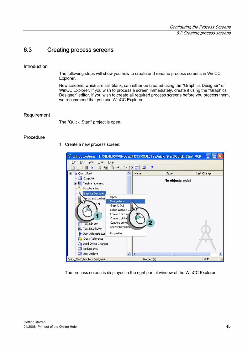
6.3 Creating process screens
Introduction The following steps will show you how to create and rename process screens in WinCC Explorer. New screens, which are still blank, can either be created using the "Graphics Designer" or WinCC Explorer. If you wish to process a screen immediately, create it using the "Graphics Designer" editor. If you wish to create all required process screens before you process them, we recommend that you use WinCC Explorer.
Requirement The "Quick_Start" project is open.
Procedure 1. Create a new process screen:
The process screen is displayed in the right partial window of the WinCC Explorer.

Configuring the Process Screens 6.3 Creating process screens
Getting started 46 04/2008, Printout of the Online Help
2. Rename the created process screen:
The process screen "START.pdl" is displayed in the right partial window of the WinCC Explorer.
3. Create a second screen analog to steps 1 and 2 and name it "SAMPLE.pdl".
Note If you rename a screen in WinCC Explorer, only use a picture name one time. The software does not check whether the name already exists. Duplicate pictures names can lead to conflicts during access via VBA or during dynamization.

Configuring the Process Screens 6.4 Editing Process Screens
Getting started 04/2008, Printout of the Online Help 47
Result You have created the process screens "START.pdl" and "SAMPLE.pdl". These are displayed in the right partial window of the WinCC Explorer. In order to graphically display the water supply of Atlanta, add several objects to the process screen "START.pdl" in the next steps.
6.4 Editing Process Screens
6.4.1 Editing Process Screens
Introduction This chapter offers a description how to edit process screens using the "Graphics Designer" editor. At the end of the chapter you will have the opportunity to deepen what you have learned by working on the screen "SAMPLE.pdl" on your own.

Configuring the Process Screens 6.4 Editing Process Screens
Getting started 48 04/2008, Printout of the Online Help
General procedure You can use the editor "Graphics Designer" to configure the process screens. The structure of this editor is similar to a drawing program and it is also operated in a similar manner. The "Graphics Designer" provides objects and tools to configure process screens. For the "Quick_Start" project you use mainly the object palette and the library of the editor "Graphics Designer". The Object Palette contains different types of objects that are frequently required for configuring process screens. The objects of the object palette cannot be added to the process screens by dragging and dropping. In order to insert an object, select it and click once with the left mouse button on the working surface of the process screen. The object palette contains the following types of objects to configure screens: ● Standard objects: e.g. line, polygon, ellipse, circle, rectangle, static text ● Smart objects: e.g. application window, picture window, OLE object, I/O field, bars, status
display ● Windows objects: e.g. button, check box, option group, slider object ● Tube objects: for example, Polygon tube, T-piece, Double T-piece, Tube bend ● Controls: The most important ActiveX controls can be found in the "Controls" tab. Other
controls can be linked. The library will help you create your pictures in a particularly efficient manner. The library contains graphic objects that you can insert by drag&drop into your screens. In the "Graphics Designer" editor you can also import graphics from external graphic programs.
6.4.2 Inserting graphic objects from the library
Introduction The following steps will show you how to insert graphic objects from the library into the process screen "START.pdl". The library is a component of the "Graphics Designer" editor. This component is a versatile tool to store and manage graphic objects. The library is split up into two areas: ● Global Library ● Project Library The area "Global library" is structured in a directory tree. It offers a variety of premade graphic objects, such as machine and system parts, measuring devices, operating controls and buildings. In the area "Project library" you can store self-made projects. You will only need the graphic objects of the area "Global library" for the "Quick_Start" project. With these objects you will depict the system for the water supply of Atlanta in the process screen "START.pdl".

Configuring the Process Screens 6.4 Editing Process Screens
Getting started 04/2008, Printout of the Online Help 49
Procedure 1. Open the process screen "START.pdl" in the "Graphics Designer":
2. Open the "Library" dialog.
The "Library" dialog is opened.
You will get a preview of the available objects with the button in the toolbar of the library. The size of the displayed symbols can be changed via the buttons and .

Configuring the Process Screens 6.4 Editing Process Screens
Getting started 50 04/2008, Printout of the Online Help
3. Open the folder "Plant Components" of the "Global library" area.
4. Insert the picture of a water tank:
The picture of the water tanks appears on the work surface.

Configuring the Process Screens 6.4 Editing Process Screens
Getting started 04/2008, Printout of the Online Help 51
5. Enlarge the picture of a water tank.

Configuring the Process Screens 6.4 Editing Process Screens
Getting started 52 04/2008, Printout of the Online Help
6. Insert the pictures of the required pipes:
The pictures of the pipes appear on the work surface.

Configuring the Process Screens 6.4 Editing Process Screens
Getting started 04/2008, Printout of the Online Help 53
7. Insert the pictures of the required valves:
The pictures of the valves appear on the work surface. 8. Close the "Library" dialog.

Configuring the Process Screens 6.4 Editing Process Screens
Getting started 54 04/2008, Printout of the Online Help
Result You have now depicted the system for the water supply in Atlanta. In order to label the displayed process, insert the "Static text" object into the process screen in the next steps.

Configuring the Process Screens 6.4 Editing Process Screens
Getting started 04/2008, Printout of the Online Help 55
6.4.3 Inserting "Static text"
Introduction The following steps will show you how to insert and edit the "Static text" object. The object "Static text" is a text field that remains unchanged in Runtime. In the "Quick_Start" project you need the static text for labeling the displayed processes. Unique labeling of the displayed processes is very important when you create multiple pictures.
Requirement The process picture "START.pdl" is opened in the "Graphics Designer" editor.
Procedure 1. Add the "Static Text" object:
The text field is displayed on the process picture.

Configuring the Process Screens 6.4 Editing Process Screens
Getting started 56 04/2008, Printout of the Online Help
2. Select the text field and set the font size to 36pt:
3. Double-click the text field and enter the title "Water_Supply_Atlanta" using the keyboard. 4. Adjust the size of the text field to the text.
5. Save the process picture "START.pdl" using the button in the toolbar. 6. Close the process screen "START.pdl".

Configuring the Process Screens 6.4 Editing Process Screens
Getting started 04/2008, Printout of the Online Help 57
Result You have added a static text field and labeled the displayed process.
6.4.4 Editing the process screen "SAMPLE.pdl"
Introduction In the following steps you will edit the process screen "SAMPLE.pdl". While editing, you display a process using the graphic objects in the library. The displaying of the process a free exercise. You do not need this step for the "Quick_Start" project. If you are uncertain about the execution of these steps, use the following teaching aids: ● Inserting graphic objects from the library
Requirement The process screen "SAMPLE.pdl" has been created. The "Graphics Designer" editor is open.

Configuring the Process Screens 6.4 Editing Process Screens
Getting started 58 04/2008, Printout of the Online Help
Procedure 1. Open the process screen "SAMPLE.pdl" via the button in the toolbar of the editor
"Graphics Designer". 2. Use the graphic object of the library to display any process.
3. Save the process screen "SAMPLE.pdl" via the button in the toolbar. 4. Close the process screen "SAMPLE.pdl". 5. Close the Graphics Designer.
Result You have edited the process screen "SAMPLE.pdl". In order to make the fill level indicator of the system in the process screen "START.pdl" dynamic, insert an entry field in the next steps and link it to the picture of the water tank via the internal tag.
See also Inserting graphic objects from the library (Page 48)

Configuring the Process Screens 6.5 Using customized menus and toolbars
Getting started 04/2008, Printout of the Online Help 59
6.5 Using customized menus and toolbars
6.5.1 Using customized menus and toolbars
Introduction In this chapter you will find description how to create screen changes usind customized menus and toolbars.
General procedure In the "Menus and Toolbars" editor you can configure customized menus and toolbars. The customized menus and toolbars are saved in a configuration file, which you assign to the project in "Computer properties" in WinCC. You connect menu items and symbols using procedures from Global Script. You can configure customized menus and toolbars as follows: ● Assigning authorizations
The elements configured in this manner are automatically disabled if a logged in user does not have the required authorization.
● Hiding or deactivating menu entries and symbols You can also exchange the configuration file, for e.g. in case of user change during runtime, if you save the modified functional scope in a new configuration file.

Configuring the Process Screens 6.5 Using customized menus and toolbars
Getting started 60 04/2008, Printout of the Online Help
6.5.2 Creating procedures for customized menus and toolbars
Introduction The following steps will show you how to create procedures in a module in Global Script. You will need two procedures in order to make the customized menus and toolbars functional: ● ActivatePicture(ByVal PictureName): Executes a screen change to the screen that is
transferred with the parameter "PictureName". ● StopRuntime(ByVal Item): Exits Runtime.
Procedure 1. Open the VBS editor:

Configuring the Process Screens 6.5 Using customized menus and toolbars
Getting started 04/2008, Printout of the Online Help 61
2. Select tab "Project module" and write the following procedure code:

Configuring the Process Screens 6.5 Using customized menus and toolbars
Getting started 62 04/2008, Printout of the Online Help
3. Save the module:

Configuring the Process Screens 6.5 Using customized menus and toolbars
Getting started 04/2008, Printout of the Online Help 63
4. Insert a new procedure:

Configuring the Process Screens 6.5 Using customized menus and toolbars
Getting started 64 04/2008, Printout of the Online Help
5. Enter a name:

Configuring the Process Screens 6.5 Using customized menus and toolbars
Getting started 04/2008, Printout of the Online Help 65
6. Write the following procedure code:
7. Save the module. 8. Close the VBS editor.
Result You have created the procedures "ActivatePicture(ByVal PictureName)" and "StopRuntime(ByVal Item)". In the following, you will create a customized menu that executes screen changes to the screens "START.pdl" and "SAMPLE.pdl". You will use a customized toolbar to exit Runtime.

Configuring the Process Screens 6.5 Using customized menus and toolbars
Getting started 66 04/2008, Printout of the Online Help
6.5.3 Creating a customized menu for screen changes
Introduction The following steps will show you how to create the customized menu "Screen change" with two menu entries "Start" and "Sample". You will link the menu entries "Start" and "Sample" with the procedure "ActivatePicture(ByVal PictureName)". Enter the name of the process screen that you wish to change to in the field "User data".
Requirement The procedure "ActivatePicture(ByVal PictureName)" has been created.
Procedure 1. Open the "Menus and toolbars" editor:

Configuring the Process Screens 6.5 Using customized menus and toolbars
Getting started 04/2008, Printout of the Online Help 67
2. Create the menu "Screen change":

Configuring the Process Screens 6.5 Using customized menus and toolbars
Getting started 68 04/2008, Printout of the Online Help
3. Create the menu entry "Start":

Configuring the Process Screens 6.5 Using customized menus and toolbars
Getting started 04/2008, Printout of the Online Help 69
4. Configure the menu entry "Start" so that a screen change to the screen "START.pdl" is executed:
5. Create the menu entry "Sample" the same wayso that a screen change to the screen "SAMPLE.pdl" is executed.

Configuring the Process Screens 6.5 Using customized menus and toolbars
Getting started 70 04/2008, Printout of the Online Help
Result You have created the menu "Screen change" with two menu entries. With the menu entries you can switch to the process screens "START.pdl" and "SAMPLE.pdl" in Runtime.

Configuring the Process Screens 6.5 Using customized menus and toolbars
Getting started 04/2008, Printout of the Online Help 71
6.5.4 Creating a customized toolbar to exit Runtime
Introduction The following steps will show you how to create a customized toolbar with a symbol to exit Runtime. You can choose any picture in bitmap format (e.g. BMP) to use as a picture for the symbol. You can create this picture e.g. with "Paint" and save it in the WinCC project directory.
Preconditions The "Menus and toolbars" editor is opened. The procedure "StopRuntime(ByVal Item)" has been created. Symbol for "Exit Runtime" has been created.
Procedure 1. Create a new toolbar:

Configuring the Process Screens 6.5 Using customized menus and toolbars
Getting started 72 04/2008, Printout of the Online Help
2. Configure the toolbar in such a way that it is displayed by default in the upper border of the picture; however the user can position it wherever required:

Configuring the Process Screens 6.5 Using customized menus and toolbars
Getting started 04/2008, Printout of the Online Help 73
3. Add a new icon to the toolbar:

Configuring the Process Screens 6.5 Using customized menus and toolbars
Getting started 74 04/2008, Printout of the Online Help
4. Configure the icon in such a way that runtime is exited:

Configuring the Process Screens 6.5 Using customized menus and toolbars
Getting started 04/2008, Printout of the Online Help 75
5. Select the picture where the icon is to be displayed.

Configuring the Process Screens 6.5 Using customized menus and toolbars
Getting started 76 04/2008, Printout of the Online Help
6. Then save the configuration:
7. Close the "Menus and toolbars" editor.
Result You have created the toolbar with an icon to exit runtime and saved the configuration. In the course of Getting Started you will also assign the configuration file to the project. At runtime, the user-defined menus and toolbars are then displayed in each process picture. If you can generate additional process images in the course of Getting Started, then you can extend the menu configuration to include the additional pictures using the steps shown.

Configuring the Process Screens 6.6 Process picture dynamics
Getting started 04/2008, Printout of the Online Help 77
6.6 Process picture dynamics
6.6.1 Process picture dynamics
Introduction This chapter offers a description how to make process screens dynamic and how to activate the "Quick_Start" project.
General procedure In the "Quick_Start" project you will make the process screen "START.pdl" dynamic by a direct tag connection. With a direct tag connection, you are connecting one tag with a dynamic object of the process screen. If the tag takes on a value in Runtime, this value is transferred directly to the dynamic object. The dynamic display of the object changes in Runtime according to the tag value. In practice, the dynamic object of a process screen is connected to a process tag. If there is a connection between WinCC and the automation system, the automation systems supplies values to the process tag. The dynamic object shows the changes of process values in Runtime. In the "Graphics Designer" editor you can configure objects that transfer values to the automation system. The automation system controls the process according to the transferred values. You do not need an automation system for the "Quick_Start" project. In this project you will connect the internal tag "Tank_Level" to the graphic picture of a water tank. Configure an I/O field to define values for the internal tag. The I/O field is an input/output field that is used to display and change tag values. If you enter a value in the I/O field in Runtime, this value is taken on by the internal tag "Tank_Level". The internal tag transfers the entered value to the graphic object that depicts the water tank. The fill level indicator of the water tank changes according to the tag value. When activating a project, WinCC Runtime is started. WinCC Runtime will execute a project in process mode. The project is then in Runtime. You will operate and observe the process in Runtime. You will define the Runtime properties in WinCC Explorer.

Configuring the Process Screens 6.6 Process picture dynamics
Getting started 78 04/2008, Printout of the Online Help
6.6.2 Making the fill level indicator dynamic
Introduction The following steps will show you how to make the fill level indicator of the water tank dynamic. The dynamization of the fill level indicator involves the following steps: ● Connecting the graphic picture of the water tank with the internal tag "Tank_Level" ● Specifying the update cycle ● Defining maximum and minimum values The connection to the internal tag "Tank_Level" allows the transfer of tag values to the graphic object that depicts the water tank. The fill level indicator of the water tank changes according to the tag values in Runtime. If there is a connection between a tag and an object, this will be displayed in the "Object properties" dialog by the symbol and by bold font. The updating cycle determines the time interval, in which the fill level indicator is updated. The maximum value corresponds to the maximum water capacity of the water tank in the "Quick_Start" project. If the tag "Tank_Level" takes on the maximum value, a full water tank is displayed on the process screen. The minimum value corresponds to an empty water tank in the "Quick_Start" project. If the tag "Tank_Level" takes on the minimum value, an empty water tank is displayed on the process screen.
Requirement ● The process screen "START.pdl" has been created. ● The internal tag "Tank_Level" has been created. ● The graphic picture of the water tank has been inserted into the process screen
"START.pdl".

Configuring the Process Screens 6.6 Process picture dynamics
Getting started 04/2008, Printout of the Online Help 79
Procedure 1. Open the process screen "START.pdl". 2. Open the "Object properties" dialog:
The "Object Properties" dialog is opened.
You can fix the "Object properties" dialog via the button . This function leaves the dialog open when another object is retrieved and shows the properties of the current object. You can exit the fixation via the button .

Configuring the Process Screens 6.6 Process picture dynamics
Getting started 80 04/2008, Printout of the Online Help
3. Open the dialog "Tag project" to link the attribute "Fill level" with a tag:
The "Tag project" dialog opens. 4. Select the internal tag "Tank_Level":
The transparent light bulb in the "Fill level" line will turn green. The "Process connection" property and the attribute "Fill level" are displayed in bold.

Configuring the Process Screens 6.6 Process picture dynamics
Getting started 04/2008, Printout of the Online Help 81
5. Set the value "2s" for the update cycle of the fill level.
6. Set 100 as the "Maximum value":
7. Analog to step 6, set 0 as a "Minimum value". 8. Close the "Object properties" dialog box.

Configuring the Process Screens 6.6 Process picture dynamics
Getting started 82 04/2008, Printout of the Online Help
Result You have connected the internal tag "Tank_Level" to the graphic picture of a water tank. This connection allows the transfer of tag values to the graphic object. By using the maximum and minimum values, you have set the display of the full and empty water tank. In order to enter or output values, add an I/O field in the process screen "START.pdl" in the next steps.
6.6.3 Inserting an I/O Field and Making it Dynamic
Introduction The following steps will show you how to insert an I/O field and how to make it dynamic. The I/O field is an input/output field that is used to display and change tag values. The dynamization of the I/O field involves the following steps: ● Connecting the I/O field with the internal tag "Tank_Level" ● Defining update ● Define attributes "Low limit value" and "High limit value" You will connect the I/O field with the internal tag "Tank_Level" in the "Quick_Start" project. This will also create an indirect connection between the I/O field and the graphic picture of a water tank. If you enter a value in the I/O field in Runtime, this value is taken on by the internal tag "Tank_Level". The tag transfers the value to the graphic object that depicts the water tank. The fill level indicator of the water tank changes according to the tag value in Runtime. With the update you will define at which time intervals the display in the I/O field will be updated. With the attributes "Low limit value" and "High limit value" you can limit the input into the I/O field to a certain value range. Values outside the configured value range are declined by the system and are not displayed.

Configuring the Process Screens 6.6 Process picture dynamics
Getting started 04/2008, Printout of the Online Help 83
Requirement The process screen "START.pdl" is opened in the "Graphics Designer" editor. The internal tag "Tank_Level" has been created.
Procedure 1. Insert an I/O field:
The I/O field appears on the work surface. The "I/O-Field Configuration" dialog opens.

Configuring the Process Screens 6.6 Process picture dynamics
Getting started 84 04/2008, Printout of the Online Help
2. Connect the tag "Tank_Level" to the created I/O field:
You can open the dialog "I/O-Field Configuration" once again by clicking on the I/O field with the right mouse button and selecting "Configuration dialog" in the shortcut menu.
3. Open the "Object properties" dialog:
The "Object Properties" dialog opens.

Configuring the Process Screens 6.6 Process picture dynamics
Getting started 04/2008, Printout of the Online Help 85
4. Set 0 as the "Low limit value":
The property "Output/Input" is in bold in the "Object properties" dialog. Here, you can see that the internal tag "Tank_Level" is connected to the I/O field. You can create the connection to a tag in the dialog "I/O-Field Configuration" dialog as well as in the dialog "Object properties".
5. Analog to step 4, set 100 as a "High limit value". 6. Close the "Object properties" dialog box. 7. Save the process screen "START.pdl". 8. Close the Graphics Designer.

Configuring the Process Screens 6.6 Process picture dynamics
Getting started 86 04/2008, Printout of the Online Help
Result You have inserted an I/O field and connected it with the internal tag "Tank_Level" If you enter a value in the I/O field in Runtime, this value is transferred to the graphic of the water tank via the internal tag. The fill level indicator of the water tank changes according to the entered value. With the attributes "Low limit value" and "High limit value" you have defined a value range for the I/O field. This value range corresponds to the capacity of the water tank. If you enter the value 0 in the I/O field in Runtime, an empty water tank is displayed. If you enter the value 100 in the I/O field in Runtime, a full water tank is displayed. Values outside the value range are declined by the system. In order to see the dynamization of the process screen "START.pdl", you will define the properties of WinCC Runtime and activate the "Quick_Start" project in the next steps.

Configuring the Process Screens 6.7 Defining the Runtime Properties
Getting started 04/2008, Printout of the Online Help 87
6.7 Defining the Runtime Properties
Introduction The following steps will show you how to define the properties for WinCC Runtime. You will define the WinCC Runtime properties in WinCC Explorer. In this chapter you will set up WinCC Runtime so that Graphics Runtime is executed when the project is activated. Choose the process screen "START.pdl" as a start screen for the Runtime window.
Requirement The "Quick_Start" project is open.
Procedure 1. Open the "Computer properties" dialog:
The "Computer Properties" dialog opens.

Configuring the Process Screens 6.7 Defining the Runtime Properties
Getting started 88 04/2008, Printout of the Online Help
2. Click the "Startup" tab and activate the application "Graphics Runtime" in the corresponding checkbox:
3. Set the process screen "START.pdl" as the startup screen:

Configuring the Process Screens 6.7 Defining the Runtime Properties
Getting started 04/2008, Printout of the Online Help 89
4. Select the configuration file for the screen navigation:

Configuring the Process Screens 6.7 Defining the Runtime Properties
Getting started 90 04/2008, Printout of the Online Help
5. Activate the window attributes "Title", "Maximize", "Minimize" and "Adapt Picture":
Result You have defined the WinCC Runtime properties. Upon activating the "Quick_Start" project, Graphics Runtime will be run. The process screen "START.pdl" is displayed as the start screen. The customized menus and toolbars are displayed in every process screen to navigate and exit Runtime. You used these window attributes to determine which additional functions the Runtime window will feature. In the next steps you will activate the project "Quick_Start".

Configuring the Process Screens 6.8 Activating the project
Getting started 04/2008, Printout of the Online Help 91
6.8 Activating the project
Introduction The following steps will show you how to activate the "Quick_Start" project and how to operate the dynamic process screen "START.pdl" in Runtime. When activating the project, WinCC Runtime is started. You execute the project in process mode in WinCC Runtime. In Runtime you will operate the configured I/O field and observe the changes in the fill level indicator.
Requirement The "Quick_Start" project is open. The Runtime Properties are defined.
Procedure 1. Activate the project "Quick_Start":
As an alternative, you can also activate a project via the button in the toolbar of the WinCC Explorer.

Configuring the Process Screens 6.8 Activating the project
Getting started 92 04/2008, Printout of the Online Help
The Runtime window will open after a short loading time. The process screen "START.pdl" will be displayed.
2. Enter values between 0 and 100 in the I/O field. Observe the changes in the fill level indicator.
3. Click on the "SAMPLE" instruction in the "Change picture" menu to switch to the process screen "SAMPLE.pdl".
4. Click on the "Start" instruction in the "Change picture" menu to switch back to the process screen "START.pdl".
5. Click on button , to exit the editing mode.
Note The button is shown with the symbol that you have created in section "Using custom menus and toolbars". You can position the toolbar for the button anywhere in the picture.
Result You have activated the "Quick_Start" project and thus started WinCC Runtime. The process screen "START.pdl" will be displayed in the Runtime window. If you enter a value in the I/O field in Runtime, this value is transferred to the graphic of the water tank via the internal tag "Tank_Level". This will enable you to observe the fill level indicator of the water tank. In order to simulate the internal tag "Tank_Level" and to test the "Quick_Start" project, you will use the WinCC TAG Simulator in the next steps.

Configuring the Process Screens 6.9 Test project
Getting started 04/2008, Printout of the Online Help 93
6.9 Test project
Introduction The following steps will show you how to test the "Quick_Start" project by means of the WinCC Tag Simulator. The WinCC TAG Simulator allows testing of a project, which is still in the development stage. During testing you will check how the project acts when connected to an automation system. In the "Quick_Start" project, you will simulate the values of the internal tags "Tank_Level" with the WinCC Tag Simulator. The WinCC Tag Simulator assigns different values to the internal tag "Tank_Level". As the internal tag with the graphic depiction is connected to the water tank, the fill level indicator of the water tank will change according to the tag values.
Requirement The WinCC TAG Simulator is installed. The Runtime Properties are defined. The "Quick_Start" project is activated.
Procedure 1. Start the WinCC Tag Simulator:
The "Simulation" dialog is opened.

Configuring the Process Screens 6.9 Test project
Getting started 94 04/2008, Printout of the Online Help
2. Open the "Tags - project" dialog and select the internal tag "Tank_Level":

Configuring the Process Screens 6.9 Test project
Getting started 04/2008, Printout of the Online Help 95
3. Define the properties of the simulation type:
4. Start WinCC TAG Simulator:
5. Position the dialog "Simulation" and the Runtime window next to one another. 6. Observe how the different simulation values affect the fill level indicator. 7. Close the "WinCC Tag Simulator" after ending the simulation.

Configuring the Process Screens 6.10 Deactivating a project
Getting started 96 04/2008, Printout of the Online Help
Result You have tested "Quick_Start" project by means of the WinCC TAG Simulator. The test shows the behavior of the project when it is supplied with process values.
6.10 Deactivating a project
Introduction The following steps will show you how to deactivate the "Quick_Start" project. You will deactivate the project "Quick_Start" in WinCC Explorer. Upon deactivating the project, the execution of the Runtime software will be terminated. The Runtime window closes.
Requirement The "Quick_Start" project is activated.
Procedure 1. Deactivate the project "Quick_Start":
The Runtime window will close after a short time.
You can also deactivate a project via the button in the toolbar of the WinCC Explorer.
Result You have deactivated the "Quick_Start" project.

Getting started 04/2008, Printout of the Online Help 97
Archiving and displaying values 77.1 Archiving and displaying values
Introduction This chapter provides information about the archive system and a description of how to save values in a process value archive.
General procedure By means of the process value archives you will display the timeline development of the process values, e. g. as a diagram or as a table. In practice, such temporal displays are very important as they allow problems to be recognized very early on. Having access to individual historic process values is another use of the process value archives. This application can, for example, help to determine how high certain values were at a time when production problems were experienced. You do not need process values for the "Quick_Start" project. Select the internal tag "Tank_Level" in this project: You will simulate the values of these tags by means of the WinCC TAG Simulator. The simulated tag values are saved in a process value archive. The sequence of the saved values will be entered into a process screen as a trend diagram and as a table. For this you will use the controls in the object palette of the "Graphics Designer" editor. Observe the changes in the simulation values in the configured controls in Runtime.
7.2 The archive system
Introduction The archive system is a partial system of WinCC. This partial system is used to archive process screens and messages.

Archiving and displaying values 7.2 The archive system
Getting started 98 04/2008, Printout of the Online Help
Components of the Archiving System The Archive System for process values is made up of a configuration and a Runtime component: ● The configuration component of the archiving system is the "Tag Logging" editor. In this
editor, you can carry out the following tasks (among others): – Configuring process value archives and compressed archives – Defining acquisition and archiving cycles – Define process values to be archived
● Tag Logging Runtime is the runtime component of the Archiving System. Tag Logging Runtime is primarily used to execute the following tasks: – Writing process values into the process value archive – Reading archived process values from the process value archive

Archiving and displaying values 7.2 The archive system
Getting started 04/2008, Printout of the Online Help 99
Archiving Process values can be stored either on hard disk in the archive database or in the main memory of Tag Logging Runtime. You can compress process values already archived to reduce the data volume.
Archiving Times An archiving cycle and events are used to control archiving times. The archiving of process values can, for example, be effected in constant time cycles or only when a process value changes by a certain amount or percentage.
Software Requirements In the WinCC Basic System, it is possible that 512 archive tags are already configured without additional licensing.

Archiving and displaying values 7.3 Starting Tag Logging
Getting started 100 04/2008, Printout of the Online Help
7.3 Starting Tag Logging
Introduction The following steps show how to start the editor "Tag Logging". In the editor "Tag Logging" you will configure a process value archive as well as the times for the acquisition and archiving cycles.
Requirement The "Quick_Start" project is open.
Procedure 1. Start the "Tag Logging" editor:
The "Tag Logging" editor will open.

Archiving and displaying values 7.4 Configuring Timers
Getting started 04/2008, Printout of the Online Help 101
Result You have opened the "Tag Logging" editor. In this editor, you will configure the times for the acquisition and archiving cycles in the next steps. You will determine the time interval, in which the tag values are captured and archived by means of the configured time.
7.4 Configuring Timers
Introduction The following steps will show you how to configure times for the acquisition and archiving cycles. The acquisition cycle determines the interval at which the process value of a process tag is read. The acquisition cycle starts as soon as WinCC Runtime is activated. Archiving cycles are time intervals in which a process value is stored in the archive database. The archiving cycle is always an integer multiple of the set acquisition cycle. The archiving cycle starts either when the WinCC Runtime activated or at a point in time defined by the user. The indication of a starting point allows the delayed archiving of the values and the distribution of the archiving load. There might be a system delay of up to the length of an acquisition cycle between acquisition and archiving.

Archiving and displaying values 7.4 Configuring Timers
Getting started 102 04/2008, Printout of the Online Help
The "Tag Logging" editor will offer you different standard times. You are not permitted to change these times. If the standard times do not suffice, configure new times. When configuring the times, you will define a time basis and a time factor. The product of the time basis and time factor determines the time distance between two archivings. So, if you set 1 second as a time basis and 5 seconds as a time factor, the process values are archived every 5 seconds. In the "Quick_Start" project, you will configure a new time for the acquisition and archiving cycles. By this time, you will determine the time interval, in which the tag values are captured and archived.
Requirement "Tag Logging" editor is open.
Procedure 1. Create a new time:
This will open the "Timers Properties" dialog.

Archiving and displaying values 7.4 Configuring Timers
Getting started 04/2008, Printout of the Online Help 103
2. Define the properties of the new time:

Archiving and displaying values 7.5 Creating Process Value Archive
Getting started 104 04/2008, Printout of the Online Help
Result You have configured a new time for the acquisition and archiving cycles. The configured time allows the acquisition and archiving of tag values every 2 seconds. In order to archive the internal tags, you will create an archive in the next steps.
7.5 Creating Process Value Archive
Introduction The following steps will show you how to create a process value archive. Archives are created in the "Tag Logging" editor by means of the Archive Wizard. The Archive Wizard offers an automated and simple method of creating an archive. With the Archive Wizard, you specify the name and type of archive. When creating process value archives, you will also define a tag whose values are archived. Once the tag has been defined, the Archive Wizard will create an archive tag in the process value archive. The values to be archived are saved in the archive tags. You will create a process value archive for the "Quick_Start" project. The values of the internal tag "Tank_Level" are saved in this archive.
Requirement "Tag Logging" editor is open.

Archiving and displaying values 7.5 Creating Process Value Archive
Getting started 04/2008, Printout of the Online Help 105
Procedure 1. Start the Archive Wizard:
This starts the Archive Wizard. The "Create archive" dialog box opens. 2. Click "Continue":

Archiving and displaying values 7.5 Creating Process Value Archive
Getting started 106 04/2008, Printout of the Online Help
3. Enter "Tank_Level_Archive" as a name for the archive and choose the archive type "Process value archive".
4. Select the internal tag "Tank_Level":

Archiving and displaying values 7.5 Creating Process Value Archive
Getting started 04/2008, Printout of the Online Help 107
5. The "Tag project" dialog opens.
6. Exit the dialog "Create archive: Step -2- " via the "Apply" button.

Archiving and displaying values 7.6 Editing the process value archive
Getting started 108 04/2008, Printout of the Online Help
Result You have created the process value archive "Tank_Level_Archive". The values of the internal tag "Tank_Level" are archived in this process value archive. In the next steps you will edit the created process value archive.
7.6 Editing the process value archive
Introduction The following steps will show you how to edit the process value archive "Tank_Level_Archive". The editing of the process value archive is carried out with the following steps: ● Renaming archive tag ● Assigning the configured time "Fill_Level" to the acquisition and archiving cycle ● Defining the saving location for the process value archive ● Defining the size of the process value archive Select the main memory in the "Quick_Start" project as your saving location for the process value archive. The main memory provides the process value archives only in Runtime. You can define the size of the process value archive by the number of data sets saved in the process value archive.

Archiving and displaying values 7.6 Editing the process value archive
Getting started 04/2008, Printout of the Online Help 109
Requirement "Tag Logging" editor is open. You have created the process value archive "Tank_Level_Archive".
Procedure 1. Open the "Process tag properties" dialog:
This will open the "Process tag properties" dialog. 2. Enter "Fill_Level_Archive" as the name for the archive tag:

Archiving and displaying values 7.6 Editing the process value archive
Getting started 110 04/2008, Printout of the Online Help
3. Click the "Archiving" tag and assign the configured time "Fill_Level" to the acquisition and archiving cycle:

Archiving and displaying values 7.6 Editing the process value archive
Getting started 04/2008, Printout of the Online Help 111
4. Open the "Process value archive properties" dialog:
5. Define the saving location and the size of the process value archive "Tank_Level_Archive".

Archiving and displaying values 7.6 Editing the process value archive
Getting started 112 04/2008, Printout of the Online Help
6. Save the process value archive via the button in the toolbar. 7. Close the "Tag Logging" editor.
Result You have edited the process value archive. The values of the internal tag "Tank_Level" are acquired every 2 seconds and are saved in the archive tag "Fill_Level_Archive". The tag values are archived in the main memory and are only available in Runtime. In order to output the saved values as a trend in Runtime, you will configure a trend window in the "Graphics Designer" editor in the next steps.

Archiving and displaying values 7.7 Configuring the Process Screen
Getting started 04/2008, Printout of the Online Help 113
7.7 Configuring the Process Screen
7.7.1 Configuring the Process Screen
Introduction This chapter offers a description how to configure a process screen, which displays the output values from the process value archive.
General procedure You will configure the process screen in the editor "Graphics Designer". For this, you will use the following objects: ● WinCC OnlineTrendControl ● WinCC OnlineTableControl The "WinCC OnlineTrendControl" object is used to create a trend window. In the trend window, the values from the process value archive are output as a trend. The output takes place in Runtime. The "WinCC OnlineTableControl" object is used to create a table window. In the table window, the values from the process value archive are output as a table. The output takes place in Runtime.

Archiving and displaying values 7.7 Configuring the Process Screen
Getting started 114 04/2008, Printout of the Online Help
7.7.2 Configuring a trend window
Introduction The following steps will show you how to configure a trend window. You will configure the trend window in the editor "Graphics Designer". For this, you will create a new process screen. Insert the object "WinCC OnlineTrendControl" into the process screen. In the "Quick_Start" project you will connect this object with the archive tag "Fill_Level_Archive". Hence, the values saved in the archive tag in Runtime are output as a trend.
Requirement You have created the process value archive "Tank_Level_Archive".
Procedure 1. Create a new process screen named "Tag_Logging.pdl" and open it in the editor
"Graphics Designer". 2. Insert the object "WinCC OnlineTrendControl" into the process screen "Tag_Logging.pdl":
The trend window will appear on the work surface in the editor "Graphics Designer". The "Properties of WinCC OnlineTrendControl" dialog opens.

Archiving and displaying values 7.7 Configuring the Process Screen
Getting started 04/2008, Printout of the Online Help 115
3. Enter "Tank_Level_Archive" as a window title for the trend window and apply the standard settings.

Archiving and displaying values 7.7 Configuring the Process Screen
Getting started 116 04/2008, Printout of the Online Help
4. Make the settings for the time axes:

Archiving and displaying values 7.7 Configuring the Process Screen
Getting started 04/2008, Printout of the Online Help 117
5. Make the settings for the value axes:

Archiving and displaying values 7.7 Configuring the Process Screen
Getting started 118 04/2008, Printout of the Online Help
6. Enter "Tank_Level" as a name for the trend and click on the button :
The "Selection of Archives/Tags" dialog will open.

Archiving and displaying values 7.7 Configuring the Process Screen
Getting started 04/2008, Printout of the Online Help 119
7. Choose the archive tag "Fill_Level_Archive" in the dialog "Selection of Archives/Tags".

Archiving and displaying values 7.7 Configuring the Process Screen
Getting started 120 04/2008, Printout of the Online Help
8. Select a time and a value axis.
9. Save the process screen "TagLogging.pdl".

Archiving and displaying values 7.7 Configuring the Process Screen
Getting started 04/2008, Printout of the Online Help 121
Result You have configured the trend window "Tank_Level_Trends". In Runtime, this window outputs the values as a trend which are saved in the archive tag "Fill_Level_Archive". In order to output the values saved in the archive tag as a table in Runtime, you will configure a table window in the "Graphics Designer" editor in the next steps.

Archiving and displaying values 7.7 Configuring the Process Screen
Getting started 122 04/2008, Printout of the Online Help
7.7.3 Configuring a table window
Introduction The following steps will show you how to configure a table window. You will configure the table window in the editor "Graphics Designer". For this, you will use the process screen "Tag_Logging.pdl". Insert the object "WinCC OnlineTableControl" into the process screen. In the "Quick_Start" project you will connect this object with the archive tag "Fill_Level_Archive". Hence, the values saved in the archive tag in Runtime are output as a table.
Requirement You have created the process value archive "Tank_Level_Archive". The process screen "Tag_Logging.pdl" is open.
Procedure 1. Insert the object "Control" into the process screen "Tag_Logging.pdl":
The table window will appear on the work surface in the editor "Graphics Designer". The "Properties of WinCC OnlineTableControl" dialog opens.

Archiving and displaying values 7.7 Configuring the Process Screen
Getting started 04/2008, Printout of the Online Help 123
2. Enter "Tank_Level_Tables" as the name for the table window:

Archiving and displaying values 7.7 Configuring the Process Screen
Getting started 124 04/2008, Printout of the Online Help
3. Enter "Tank_Level" as a name for the value column and click on the button :
The "Selection of Archives/Tags" dialog will open.

Archiving and displaying values 7.7 Configuring the Process Screen
Getting started 04/2008, Printout of the Online Help 125
4. Choose the archive tag "Fill_Level_Archive" in the dialog "Selection of Archives/Tags".
5. Click "OK" to close the "Properties of WinCC OnlineTableControl" dialog. 6. Save the process screen "Tag_Logging.pdl". 7. Close the Graphics Designer.

Archiving and displaying values 7.7 Configuring the Process Screen
Getting started 126 04/2008, Printout of the Online Help
Result You have configured the table window "Tank_Level_Tables". In Runtime, this window outputs the values as a table, which are saved in the archive tag "Fill_Level_Archive". In order to view the output values in Runtime, you will define the properties of WinCC Runtime in the next steps.

Archiving and displaying values 7.8 Modifying a customized menu for screen changes
Getting started 04/2008, Printout of the Online Help 127
7.8 Modifying a customized menu for screen changes
Introduction The following steps will show you how to expand the custom menu "Picture change" with menu entry "Tag Logging". You will link the menu entry "Tag Logging" with the procedure "ActivatePicture(ByVal PictureName)". Enter the name of the process screen that you wish to change to in the field "User data".
Requirement The procedure "ActivatePicture(ByVal PictureName)" has been created. The custom menu "Picture change" is created for process pictures "START.pdl" and "SAMPLE.pdl".
Procedure 1. Open the "Menus and toolbars" editor:

Archiving and displaying values 7.8 Modifying a customized menu for screen changes
Getting started 128 04/2008, Printout of the Online Help
2. Create the menu entry "Tag Logging":

Archiving and displaying values 7.8 Modifying a customized menu for screen changes
Getting started 04/2008, Printout of the Online Help 129
3. Configure the menu entry "Tag Logging" so that a screen change to the screen "Tag_Logging.pdl" is executed:
4. Save the changes that you have made in the "Menus and Toolbars" editor. 5. Close the "Menus and toolbars" editor.
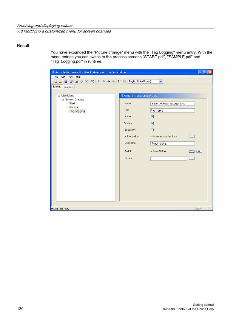
Archiving and displaying values 7.8 Modifying a customized menu for screen changes
Getting started 130 04/2008, Printout of the Online Help
Result You have expanded the "Picture change" menu with the "Tag Logging" menu entry. With the menu entries you can switch to the process screens "START.pdl", "SAMPLE.pdl" and "Tag_Logging.pdl" in runtime.

Archiving and displaying values 7.9 Defining the Runtime Properties
Getting started 04/2008, Printout of the Online Help 131
7.9 Defining the Runtime Properties
Introduction The following steps will show you how to define the properties for WinCC Runtime. In this chapter we will set up WinCC Runtime so that Tag Logging Runtime is executed when the project is activated. Choose the process screen "Tag_Logging.pdl" as a start screen for the Runtime window.
Requirement The "Quick_Start" project is open. The process screen "Tag_Logging.pdl" has been created.
Procedure 1. Open the "Computer properties" dialog:
The "Computer Properties" dialog is opened.

Archiving and displaying values 7.9 Defining the Runtime Properties
Getting started 132 04/2008, Printout of the Online Help
2. Click the "Startup" tab and activate the application "Tag Logging Runtime" in the corresponding checkbox:
3. Define the process screen "Tag_Logging.pdl" as a start screen:

Archiving and displaying values 7.9 Defining the Runtime Properties
Getting started 04/2008, Printout of the Online Help 133
4. Exit the "Computer Properties" dialog by clicking "OK".
Result You have defined the WinCC Runtime properties. When activating the "Quick_Start" project, Tag Logging Runtime is executed and the process screen "Tag_Logging.pdl" will be displayed. In the next steps you will activate and test the project "Quick_Start".

Archiving and displaying values 7.10 Activating and testing the project
Getting started 134 04/2008, Printout of the Online Help
7.10 Activating and testing the project
Introduction The following steps will show you how to activate and test the "Quick_Start" project. You test the "Quick_Start" project by means of the WinCC TAG Simulator. The WinCC Tag Simulator assigns values to the internal tag "Tank_Level" in Runtime. These values are acquired every 2 seconds in the "Quick_Start" project and saved in the archive tag "Fill_Level_Archive". Tag Logging Runtime reads the archives values and transfers them to the trend window and the table window. The values are output as a trend and as a table.
Requirement The WinCC TAG Simulator is installed. The "Quick_Start" project is open. The Runtime Properties are defined.

Archiving and displaying values 7.10 Activating and testing the project
Getting started 04/2008, Printout of the Online Help 135
Procedure 1. Activate the "Quick_Start" project via the button in the toolbar of the WinCC Explorer. 2. Start the WinCC Tag Simulator. 3. Open the "Tags - project" dialog and select the internal tag "Tank_Level":

Archiving and displaying values 7.10 Activating and testing the project
Getting started 136 04/2008, Printout of the Online Help
4. Define the properties of the simulation type:
5. Start the WinCC Tag Simulator:
6. Observe the output of the simulation values in the process screen "Tag_Logging.pdl".

Archiving and displaying values 7.10 Activating and testing the project
Getting started 04/2008, Printout of the Online Help 137
7. Close the "WinCC Tag Simulator" after ending the simulation.
8. Deactivate the "Quick_Start" project via the button in the toolbar of the WinCC Explorer.
Result You have activated the "Quick_Start" project and simulated the values of the internal tags "Tank_Level". The value sequence is displayed in the configured trend and table windows.

Archiving and displaying values 7.10 Activating and testing the project
Getting started 138 04/2008, Printout of the Online Help

Getting started 04/2008, Printout of the Online Help 139
Outputting values from the process archive 88.1 The message report system
Introduction The message report system is a partial system of WinCC, which is used to document configuration and Runtime data. Configuration data are output as reports. Configuration data can be the tags, functions or graphics used in the project. Runtime data are output as reports. A report can contain the following Runtime data: ● All occurred messages in chronological order - message sequence report ● Messages from a particular message archive - archive report ● Current messages from the message list - message report ● Messages from a particular process value and compressed archive ● Data from other applications not originating in WinCC. There are various log objects
available for integrating this kind of data in a WinCC log.
Components of the Report System The report system is made up of a configuration and a Runtime component: ● The configuration component of the report system is the "Report Designer" editor. The
"Report Designer" editor contains the components "Layouts" and Print jobs". These components contain predefined standard layouts and print jobs that can be edited. In the editor "Report Designer" you can create new layouts and print jobs. The editor "Report Designer" provides two additional tools to create and edit the layouts. These are the page layout editor and the line layout editor.

Outputting values from the process archive 8.1 The message report system
Getting started 140 04/2008, Printout of the Online Help
● Report Runtime is the runtime component of the Report System. Report Runtime is primarily used to execute the following tasks: – Reading the values to be documented from archives or controls – Controlling printouts
Output Media The editor "Report Designer" offers the following possible outputs of reports and logs: ● A printer ● A file ● The screen

Outputting values from the process archive 8.2 Outputting values from the process archive
Getting started 04/2008, Printout of the Online Help 141
8.2 Outputting values from the process archive
Introduction This chapter provides information about the logging system and a description of how to log values from the process value archive.
General procedure The logging system documents configuration and Runtime data. Configuration data can be system screens with their objects, created user groups as well as tables with the used tags. Runtime data can be process values from the process value archives or compressed archives as well as messages from message archives or message lists. The documented data will be saved as a report or a log. Either a page or a line layout is used for the reports and logs. In the layouts you configure the external appearance and data supply for output of a report. The output of the logs and the reports are controlled by the print jobs. The following parameters are primarily defined in the print jobs: ● Time control ● Output medium ● Extent of the output In the "Quick_Start" project you will document the values from the process value archive "Tank_Level_Archive". You will output these values in a log. For the log, you will create a new page layout and determine the parameters of the print job. You will link the print job with a configurable button of the table window. The output of the report is triggered in Runtime via this button. The archive values are documented in the output log, which are displayed in the current view of the table window.
8.3 Creating a Page Layout
Introduction The following steps will show you how to create and rename a page layout in WinCC Explorer. The page layout is a template that contains different objects to output data. You will determine via the objects of the page layout which information and design features appear in a report or log. WinCC already provides preconfigured layouts for most applications. These layouts can be edited with the "Report Designer" editor to suit your requirements. Page layouts can be language-neutral and language-dependent. You will create a new page layout with the editor "Report Designer" for the "Quick_Start" project. You will use this page layout as a template for the message report, in which the values from the process value archive are documented.

Outputting values from the process archive 8.3 Creating a Page Layout
Getting started 142 04/2008, Printout of the Online Help
Requirement The "Quick_Start" project is open.
Procedure 1. Create a new language-neutral page layout in the WinCC Explorer:
The new layout file "NewRPL0.RPL" is stored and shown in the "Language neutral" directory.

Outputting values from the process archive 8.3 Creating a Page Layout
Getting started 04/2008, Printout of the Online Help 143
2. Open the "New name" dialog to rename the page layout:
3. As the name of the layout file "Tag_Logging.rpl", enter:
The name of the page layout will be changed.

Outputting values from the process archive 8.4 Editing the Page Layout
Getting started 144 04/2008, Printout of the Online Help
Result You have a created and renamed a new page layout in WinCC Explorer. In the "Quick_Start" project you will use this page layout as a template for the message report, in which the values from the process value archive are documented. In order to determine the contents and design features of the message report, you will edit the page layout in the next steps.
8.4 Editing the Page Layout
8.4.1 Editing the Page Layout
Introduction This chapter offers a description how to edit a page layout using the page layout editor.

Outputting values from the process archive 8.4 Editing the Page Layout
Getting started 04/2008, Printout of the Online Help 145
The editing of the page layout consists of the following steps: ● Establishing properties of the entire page layout ● Deactivating the output of the cover sheet ● Determine log content ● Editing the header and footer
General procedure For a page layout, properties can be defined that will be applied to all pages of the page layout. You define a format and the print margins for the pages of the page layout "Tag_Logging" in the "Quick_Start" project. Each page layout consists of three pages: ● Cover sheet ● Contents of Report ● Final page The cover sheet is the first page of a log or a report. The output of the cover sheet is preset in the page layout editor. In this chapter you will change that predefined setting, so that the page "Cover Sheet" will not be output. On the page "Report content" you will define the setup and content of a log or a report. The output of the report content is mandatory. To document the values from the process value archive, use dynamic object "WinCC Control Runtime Printprovider" in the "Quick_Start" project. You can choose between objects "WinCC Control Runtime Printprovider Table" and "WinCC Control Runtime Printprovider Picture". The full content of the table is output in the table and the current display for the WinCC Control is output in the picture. The log output is only possible via buttons in the WinCC Control for both variants. The final page is a last page of a log or a report. The output of the final page is not preset in the editor "Report Designer". The output of the final page is not intended in the "Quick_Start" project. Each page of the page layout contains a static layer and a dynamic layer. The header and footer are defined in the static level of a page layout. The static level serves to output the company name, the company logo, the time and the number of pages. The dynamic level contains the dynamic objects for outputting the configuration and Runtime data. In the static level, only static objects and system objects can be inserted. In the dynamic layer, static and dynamic objects can be inserted. The objects of the object palette cannot be added to the page layout by dragging and dropping. In order to insert an object from the object palette, select it and click once with the left mouse key on the working surface of the page layout. In the "Quick_Start" project, add the system object "Project name" into the header of the page "Report content". This object is used to display the project name. In the footer you will insert the system object "Page number". The system object "Page number" allows the page numbering in the log.

Outputting values from the process archive 8.4 Editing the Page Layout
Getting started 146 04/2008, Printout of the Online Help
8.4.2 Establishing properties of the page layout
Introduction The following steps will show you how to start the page layout editor and how to define the properties for the entire page layout. The page layout editor is a component of the editor "Report Designer" and is used to create and edit page layouts. The page layout editor can only be used for the project currently open in the WinCC Explorer. The layouts are saved are the basis of their projects. You will use the page layout editor to edit the "Tag_Logging" page layout in this chapter. By editing the layout you will determine the setup and content of the log to be output. For the "Quick_Start" project, define the following properties for the "Tag_Logging" page layout: ● Paper size ● Print margins ● Output of the page "Cover Sheet" The paper size shows the total area of the layout. The paper size determines the output format of the log. The print margins define the non-printable marginal area. This area is by default greyed in the page layout editor and cannot be edited. You will define in the "Object properties" dialog of the page layout whether the log will be output with a first (cover) page. In this chapter you will deactivate the output of a Cover Sheet.
Requirement The layout file "Tag_Logging.rpl" is created.

Outputting values from the process archive 8.4 Editing the Page Layout
Getting started 04/2008, Printout of the Online Help 147
Procedure 1. Open the "Tag_Logging.rpl" layout file in the page layout editor:
The "Tag_Logging.rpl" layout file opens in the page layout editor.

Outputting values from the process archive 8.4 Editing the Page Layout
Getting started 148 04/2008, Printout of the Online Help
2. Open the "Object properties" dialog of the page layout:
The "Object Properties" dialog is opened. 3. Define the following values for the parameters of the property "Geometry":
– Paper size: Letter – Left print margin: 2 cm – Right print margin: 2 cm – Top print margin: 2 cm – Bottom print margin: 2 cm
Note The units can be changed from "cm" to "inch" using the Report Designer settings. Open the "Settings" dialog via the "Tools ->Settings" menu. Select the unit "inch" on the "Units" tab in the area "Coordinates". Convert the indicated values from "cm" to "inch". The following rules apply: 1cm = 0,3937 Inch.

Outputting values from the process archive 8.4 Editing the Page Layout
Getting started 04/2008, Printout of the Online Help 149
4. Deactivate the output of the page "Cover Sheet":
5. Close the "Object properties" dialog.
Result You have defined the page format and the print margins for the "Tag_Logging" page layout. This defines the printable and non-printable areas of the pages. The predefined output of the page "Cover Sheet" has been changed. In order to define the log content, you will edit the page "Report content" of the page layout in the next steps.

Outputting values from the process archive 8.4 Editing the Page Layout
Getting started 150 04/2008, Printout of the Online Help
8.4.3 Determine log content
Introduction The following steps will show you how to define the log content. On the page "Report content" of the page layout you will define the content of the message report. For this you will use the objects from the object palette of the page layout editor. You will insert the "WinCC Control Runtime Provider Table" object, which will be used for displaying the values from the process value archive.
Requirement The "Tag_Logging.rpl" layout file opens in the page layout editor.
Procedure 1. Open the page "Report content" of the page layout:

Outputting values from the process archive 8.4 Editing the Page Layout
Getting started 04/2008, Printout of the Online Help 151
2. Change to the dynamic level of the page "Report content":
3. Insert the "WinCC Control Runtime Provider Table" object into the "Tag_Logging.rpl" page layout:

Outputting values from the process archive 8.4 Editing the Page Layout
Getting started 152 04/2008, Printout of the Online Help
4. Open the "Object Properties" dialog:
5. Click the "Properties" tab and define the following values for the "Geometry" property: – Width: 16 cm – Height: 18 cm – PositionX: 3 cm – PositionY: 5 cm

Outputting values from the process archive 8.4 Editing the Page Layout
Getting started 04/2008, Printout of the Online Help 153
6. Occupy the attribute "Column" with the value "1" for the "Geometry" property.
7. Close the "Object Properties" dialog box.

Outputting values from the process archive 8.4 Editing the Page Layout
Getting started 154 04/2008, Printout of the Online Help
Result You have inserted the "WinCC Control Runtime Provider Table" object. This enables the values to be read from the process value archive and are documented in the log "Tag_Logging.rpl". In order to output the project name with the log, you will edit the header of the page "Report content" in the next steps.
8.4.4 Editing the header
Introduction The following steps will show you how to edit the header of the page "Report content". The header is located on the static level of the page layout. The header is defined individually for the pages "Cover Sheet", "Report content" and for the last page. In the "Quick_Start" project, you will only edit the header of the page "Report content". In the header you will insert the system object "Project name". This object will serve as a wildcard for the display of the project name in the log.

Outputting values from the process archive 8.4 Editing the Page Layout
Getting started 04/2008, Printout of the Online Help 155
Requirement The "Tag_Logging.rpl" layout file opens in the page layout editor.
Procedure 1. Open the page "Report content" of the page layout in the "View" menu. 2. Change to the static level of the page "Report content":
3. Insert the system object "Project name" into the header:

Outputting values from the process archive 8.4 Editing the Page Layout
Getting started 156 04/2008, Printout of the Online Help
4. Open the "Object Properties" dialog:
The "Object Properties" dialog is opened. 5. Define the following values for the parameters of the property "Geometry":
– Width: 12 cm – Height: 1 cm – PositionX: 2 cm – PositionY: 2 cm

Outputting values from the process archive 8.4 Editing the Page Layout
Getting started 04/2008, Printout of the Online Help 157
6. Define "No line" as the line style of the inserted object:
7. Close the "Object Properties" dialog box.
Result You have inserted the system object "Project name" into the header of the page "Report content". This object is used to display the project name in the log. In order to number the pages of the log, you will edit the footer in the next steps.

Outputting values from the process archive 8.4 Editing the Page Layout
Getting started 158 04/2008, Printout of the Online Help
8.4.5 Editing the footer
Introduction The following steps will show you how to edit the footer of the page "Report content". The footer is located on the static level of the page layout. The footer is defined individually for the pages "Cover Sheet", "Report content" and for the last page. In the "Quick_Start" project, you will only edit the footer of the page "Report content". You will edit the footer by inserting the system object "Page number" from the object palette of the page layout editor. This object will serve as a wildcard for the display of the page numbers in the log.
Requirement The "Tag_Logging.rpl" layout file opens in the page layout editor.
Procedure 1. Open the page "Report content" of the page layout. 2. Change to the static level of the page "Report content". 3. Insert the system object "Page number" into the footer:

Outputting values from the process archive 8.4 Editing the Page Layout
Getting started 04/2008, Printout of the Online Help 159
4. Open the "Object Properties" dialog:
The "Object Properties" dialog is opened. 5. Define the following values for the parameters of the property "Geometry":
– Width: 1 cm – Height: 1 cm – PositionX: 18 cm – PositionY: 24 cm

Outputting values from the process archive 8.4 Editing the Page Layout
Getting started 160 04/2008, Printout of the Online Help
6. Define "No line" as the line style of the inserted object:
7. Close the "Object Properties" dialog box.
8. Save the "Tag_Logging.rpl" layout file with the button in the toolbar. 9. Close the "Report Designer".
Result You have inserted the system object "Page number" into the footer of the page "Report content". This object allows the numbering of the pages in the log.
Outputting values from the process archive 8.5 Editing the print job
Getting started 04/2008, Printout of the Online Help 161
8.5 Editing the print job
8.5.1 Editing the print job
Introduction This chapter offers a description how to edit a print job.
General procedure Print jobs in WinCC are of central importance to the output of project and Runtime documentation. In the print jobs you configure the output medium, how much is to be printed, the time at which printing is to start, and other output parameters. For the output, each layout is linked to a print job. WinCC comes with numerous predefined print jobs. These print jobs are already associated with certain WinCC applications. Therefore, these predefined print jobs can be neither deleted nor renamed. Only certain settings can be changed with these predefined print jobs. You will use a predefined print job in the project "Quick_Start". This instruction is connected with the "Tag_Logging" page layout. This outputs the lot with the "Tag_Logging" page layout. You will also define the output medium for the output of the log.
The print job is executed via the button in the toolbar of the table window. In order to link this button with the desired print job, you will edit the table window "Tank_Level_Tables" in the "Quick_Start" project.
8.5.2 Defining and editing the Print Job
Introduction The following steps will show you how to define and edit a print job for the output of the log. Use the predefined print job "@OnlineTableControl - Table" for the "Quick_Start" project. The editing of this print job is carried out with the following steps: ● Linking a print job to a page layout ● Defining the output medium

Outputting values from the process archive 8.5 Editing the print job
Getting started 162 04/2008, Printout of the Online Help
This print job is linked with the "Tag_Logging.rpl" page layout. With this, the log will adapt the design features and settings that are defined in this page layout. You will define any printer as the output medium for the log. If you do not have a printer, you can print the log to a file. More information on this topic can be found in the "Project documentation" in chapter "Working with WinCC > Documentation on configuration and runtime data > Project documentation > How to set up a new print job".
Requirement The "Quick_Start" project is open. The page layout "Tag_Logging.rpl" has been created.
Procedure 1. Select the component "Print jobs" of the "Report Designer" editor in the WinCC Explorer.
The predefined print jobs are displayed.

Outputting values from the process archive 8.5 Editing the print job
Getting started 04/2008, Printout of the Online Help 163
2. Choose print job "@OnlineTableControl - Table" and open the "Print job properties" dialog:

Outputting values from the process archive 8.5 Editing the print job
Getting started 164 04/2008, Printout of the Online Help
3. Connect the print job with the "Tag_Logging.rpl" layout file:
4. Click the "Select printer" tab and activate the print output "Printer":

Outputting values from the process archive 8.5 Editing the print job
Getting started 04/2008, Printout of the Online Help 165
5. Link the print job to an available printer:
Result You have now defined and edited the print job for the output of the log. The log is based on the "Tag_Logging" page layout. The log will be output on the printer. In order to execute the print job in Runtime, you will link a button in the table window with the print job in the next steps.

Outputting values from the process archive 8.6 Defining the Runtime Properties
Getting started 166 04/2008, Printout of the Online Help
8.6 Defining the Runtime Properties
Introduction The following steps will show you how to define the properties for WinCC Runtime. Choose the process screen "Tag_Logging.pdl" as a start screen for the Runtime window.
Requirement The "Quick_Start" project is open. The process screen "Tag_Logging.pdl" has been created.
Procedure 1. Open the "Computer properties" dialog:
The "Computer Properties" dialog is opened.

Outputting values from the process archive 8.7 Activating and testing the project
Getting started 04/2008, Printout of the Online Help 167
2. Define the process screen "Tag_Logging.pdl" as a start screen for the Runtime window:
3. Exit the "Computer Properties" dialog by clicking "OK".
Result You have defined the WinCC Runtime properties. The Report Runtime is run when you activate the "Quick_Start" project. The process screen "Tag_Logging.pdl" is displayed as the start screen. You will activate the "Quick_Start" project in the next steps and use the WinCC TAG Simulator.
8.7 Activating and testing the project
Introduction The following steps will show you how to activate and test the "Quick_Start" project. You test the "Quick_Start" project by means of the WinCC TAG Simulator. The WinCC Tag Simulator assigns values to the internal tag "Tank_Level" in Runtime. These values are acquired every 2 seconds in the "Quick_Start" project and saved in the archive tag "Fill_Level_Archive". Tag Logging Runtime reads the archives values and transfers them to the trend window and the table window. The values are output as a trend and as a table.
Requirement The WinCC TAG Simulator is installed. The "Quick_Start" project is open. The Runtime Properties are defined.

Outputting values from the process archive 8.7 Activating and testing the project
Getting started 168 04/2008, Printout of the Online Help
Procedure 1. Activate the "Quick_Start" project via the button in the toolbar of the WinCC Explorer. 2. Start the WinCC Tag Simulator. 3. Open the "Tags - project" dialog and select the internal tag "Tank_Level":

Outputting values from the process archive 8.7 Activating and testing the project
Getting started 04/2008, Printout of the Online Help 169
4. Define the properties of the simulation type:
5. Start the WinCC Tag Simulator:

Outputting values from the process archive 8.7 Activating and testing the project
Getting started 170 04/2008, Printout of the Online Help
Result You have activated the "Quick_Start" project and simulated the values of the internal tags "Tank_Level". The course of the internal tags "Tank_Level" is displayed in the trend window and the table window. Print a protocol in the next steps to document the values from the current view of table window.

Outputting values from the process archive 8.8 Printing log
Getting started 04/2008, Printout of the Online Help 171
8.8 Printing log
Introduction The following steps will show you how to print a log. In this chapter you will print a log, in which the values from the current view of the table window are documented. This requires that you use the button "Print" from the table window. In order to use the button, you will stop the update of the data via the button . The data is saved to the clipboard and added when the button is clicked again. By actuating the "Print log" button in runtime, the print job "@OnlineTableControl - Table" is executed and the log is printed. The log is based on the page layout "Tag_Logging.rpl".
Requirement The "Quick_Start" project is activated. The WinCC TAG Simulator is started. The "@ OnlineTableControl - Table " print job is connected with the "Print" button.
Procedure 1. Stop the data update via the button :
The data update display is stopped.

Outputting values from the process archive 8.8 Printing log
Getting started 172 04/2008, Printout of the Online Help
2. Click on the "Print" button to print the log out.
The log is printed. 3. End the simulation:
4. Deactivate the "Quick_Start" project via the button in the toolbar of the WinCC Explorer.

Outputting values from the process archive 8.8 Printing log
Getting started 04/2008, Printout of the Online Help 173
Result You have just printed a log. The printed log consists of a page, in which the values from the current view of the table window are documented.

Outputting values from the process archive 8.8 Printing log
Getting started 174 04/2008, Printout of the Online Help

Getting started 04/2008, Printout of the Online Help 175
Configuring messages 99.1 Configuring messages
Introduction This chapter provides information about the message system and a description of how to configure messages in the "Alarm Logging" editor.
General procedure The message system monitors the processes. In the "Alarm Logging" editor of the message system you can configure the following message types: ● Bit messages: Display status changes in the process. The bit messages are triggered by
the PLC. ● Analog messages: Show two trangressions or non-achieved limit values. The analog
messages are triggered when the set limit values are exceeded or not met. In the "Quick_Start" project, you will configure messages to monitor the fill level and the supply valve of the water tank. You will simulate the fill level of the water tank in the "Quick_Start" project by the values of the internal tag "Tank_Level". You will set a lower and high limit for the fill level. If the values of the internal tag "Tank_Level" violate a limit, the corresponding analog message is triggered and displayed in Runtime. In order to simulate the status of the supply valve, create a new internal tag in WinCC Explorer. In the "Alarm Logging" editor you will configure bit messages for the different statuses of the supply valve. A bit message is triggered when a certain bit is set in the tag value.

Configuring messages 9.2 The message system enables the following:
Getting started 176 04/2008, Printout of the Online Help
9.2 The message system enables the following:
Introduction The message system is a partial system of WinCC, which is used to monitor the processes. With certain statuses and changes in the process, the message system generates messages and outputs them as tables in Runtime. The messages help identify critical situations early so that downtimes can be avoided.
Components of the Alarm System The message system is made up of a configuration and a Runtime component. ● The configuration component of the message system is the "Alarm Logging" editor. In the
"Alarm Logging" editor you can execute the following tasks: – Creating alarms – Preparing messages – Setting Limit Values – Message text and message status display – Define acknowledgment properties of the messages – Define archiving properties of the messages
● Alarm Logging Runtime is the runtime component of the message system. Alarm Logging Runtime is primarily used to execute the following tasks: – Execution of the defined monitors – Controlling the message output – Administering acknowledgments

Configuring messages 9.2 The message system enables the following:
Getting started 04/2008, Printout of the Online Help 177

Configuring messages 9.3 Start alarm logging
Getting started 178 04/2008, Printout of the Online Help
9.3 Start alarm logging
Introduction The following steps show how to start the editor "Alarm Logging". In the "Alarm Logging" editor you will configure all bit and analog messages needed for the "Quick_Start" project.
Requirement The "Quick_Start" project is open.
Procedure 1. Start the "Alarm Logging" editor:
The "Alarm Logging" editor will open.

Configuring messages 9.4 Setting message blocks and message classes
Getting started 04/2008, Printout of the Online Help 179
Result You have opened the "Alarm Logging" editor. In the next steps you will define the message blocks and message classes.
9.4 Setting message blocks and message classes
Introduction The following steps will show you how to set message blocks and message classes for the messages in the "Quick_Start" project. The messages are displayed in a table in runtime. Each message is composed of information that is shown in the columns of the table. These individual pieces of information are referred to as message blocks. Each message block corresponds to one column in the table. The message blocks are subdivided into three groups: ● System blocks with system data, for example date, time, message number and status.
System blocks are predefined. ● User text blocks with explanatory texts, for example, the message text containing
information on the location and cause of a fault The texts are freely customizable. ● Process value blocks are used to link the messages to process values, for example
current fill levels, temperatures or speeds. Messages with similar behavior can be allocated to a message class. The message classes allow a central management of individual messages. The message blocks and messages classes are defined in the "Quick_Start" project using the System Wizard. The System Wizard offers an automated and simple method of defining message blocks and message classes.

Configuring messages 9.4 Setting message blocks and message classes
Getting started 180 04/2008, Printout of the Online Help
Requirement "Alarm Logging" editor is open.
Procedure 1. Open the "Select wizard" dialog:
The "Select Wizard" dialog is opened. 2. Select the "System Wizard" entry.
The "System Wizard" dialog is opened.

Configuring messages 9.4 Setting message blocks and message classes
Getting started 04/2008, Printout of the Online Help 181
3. Click the "Next" button in the first dialog-box. 4. Define the message blocks that are to be displayed at runtime.

Configuring messages 9.4 Setting message blocks and message classes
Getting started 182 04/2008, Printout of the Online Help
5. Define a message class for the messages in the "Quick_Start" project:
6. Confirm the settings you have done by clicking the "Apply" button:

Configuring messages 9.5 Changing the length of the user text blocks
Getting started 04/2008, Printout of the Online Help 183
Result You have defined the message blocks for the messages in the "Quick_Start" project. The messages are compiled from the following message blocks at runtime:
System blocks: Date, time, number User text blocks: Message Text, Fault Location Process value blocks: none
You have also defined a message class using the System Wizard. The messages in the "Quick_Start" project belong to the Error message class. Change the length of the user text blocks in the next steps to enter longer texts in the user text blocks.
9.5 Changing the length of the user text blocks
Introduction The following steps show you how to change the length of the user text blocks. The length of a user text block determines the number of characters that can be entered into this block. The maximum string length is 255 characters. In the "Quick_Start" project you will define a length of 30 characters for the user text block "Message text". The length of the user text block "Point of error" is 25 characters in the "Quick_Start" project.
Requirement "Alarm Logging" editor is open. The user text blocks "Message Text" and "Point of Error" have been created.

Configuring messages 9.5 Changing the length of the user text blocks
Getting started 184 04/2008, Printout of the Online Help
Procedure 1. Open the "Message blocks" dialog:
The "Message blocks" dialog is opened. 2. Change the specified length of the user text block "Message text" to 30 characters:
3. Change the length of the user text block "Fault Location" to 25 characters by following the instructions in steps 1 and 2.

Configuring messages 9.6 Configuring bit messages
Getting started 04/2008, Printout of the Online Help 185
Result You have changed the length of the user text blocks "Message Text" and "Fault Location". The user text block "Message Text" contains maximum 30 characters. The maximum number of characters in the user text block "Fault Location" is 25 characters. In the next steps configure the 3 bit messages to monitor the status changes of the supply valve.
9.6 Configuring bit messages
9.6.1 Configuring bit messages
Introduction This chapter provides a description of how to configure bit messages in the "Alarm Logging" editor.
General procedure The bit messages show status changes in the process and are initiated by the PLC. You will create three bit messages in the "Alarm_Logging" editor for the "Quick_Start" project. Each bit message corresponds to a certain status of the supply valve at the water tank. If the status of the supply valve changes, a corresponding bit message will be triggered and displayed in Runtime. Which bit message is triggered with what status of the supply valve is determined during the editing of the bit messages. You will define specific properties for each bit message.
9.6.2 Creating bit messages
Introduction The following steps show how to create bit messages in the editor "Alarm Logging". You will need three bit messages for the "Quick_Start" project. Through these messages, the following statuses of the supply valve are displayed in Runtime. ● Valve_open (valve open) ● Valve_closed (valve closed) ● Valve_inop (valve failed) As the first bit message was automatically created by the "Alarm Logging", you will only create two bit messages. The bit messages are automatically numbered in the "Alarm_Logging" editor.

Configuring messages 9.6 Configuring bit messages
Getting started 186 04/2008, Printout of the Online Help
Requirement "Alarm Logging" editor is open.
Procedure 1. Create a new bit message in the "Alarm_Logging" editor:
The new bit message is displayed in the "Alarm_Logging" editor. 2. Analog to step 1, create another bit message in the "Alarm_Logging" editor.

Configuring messages 9.6 Configuring bit messages
Getting started 04/2008, Printout of the Online Help 187
Result You have created the bit messages in the "Alarm Logging" editor that you will need for the "Quick_Start" project. The created bit messages are displayed in the table window of the "Alarm_Logging" editor. In order to determine the behavior and the content of the bit messages in Runtime, you will define the properties of the bit messages in the next steps.
9.6.3 Editing bit messages
Introduction The following steps show you how to define the properties of the bit messages in the editor "Alarm Logging". In the "Quick_Start" project you will define the following properties for each bit message: ● Message tag ● Message bit ● Message text ● Point of error The message tag is linked to the status changes in the process. If a status change takes place in the process, a bit is set in the tag value. Depending on the tag values, a bit message is triggered.

Configuring messages 9.6 Configuring bit messages
Getting started 188 04/2008, Printout of the Online Help
In the "Quick_Start" project, you will create a new internal tag to simulate the different statuses of the supply valve. You will set this tag as a message tag for the created bit messages. One of the bit message is triggered when a certain bit is set in the tag value. You can define which bit triggers a bit message by means of the property "Message bit". The message text describes the status of the supply valve, e.g. "Valve open" in the "Quick_Start" project. The point of error describes the location of the status change.
Requirement The "Quick_Start" project is open. "Alarm Logging" editor is open.
Procedure 1. Create a new internal tag in the WinCC Explorer. Enter "Inflow_Valve" as a name for the
tag and choose the data type "Unsigned 16 bit value". 2. Open the "Single message" dialog to define the properties of the first bit message:
The "Single Message" dialog is opened.
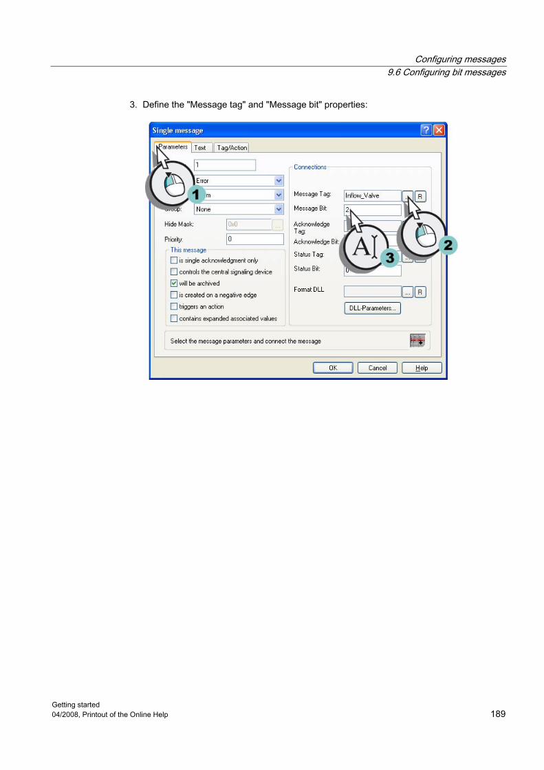
Configuring messages 9.6 Configuring bit messages
Getting started 04/2008, Printout of the Online Help 189
3. Define the "Message tag" and "Message bit" properties:

Configuring messages 9.6 Configuring bit messages
Getting started 190 04/2008, Printout of the Online Help
4. Click the "Texts" tab and define the properties "Message text" and "Point of error":
5. Analog to step 2, create the following properties for the second bit message: – Message tag: "Inflow_Valve" – Message bit: 3 – Message text: "Valve_closed" – Point of error: "Valve"
6. Analog to step 2, create the following properties for the third bit message: – Message tag: "Inflow_Valve" – Message bit: 4 – Message text: "Valve_inop" – Point of error: "Valve"
7. Save the settings via the button in the toolbar.

Configuring messages 9.6 Configuring bit messages
Getting started 04/2008, Printout of the Online Help 191
Result You have defined the properties of the bit messages for the "Quick_Start" project. This controls the output of the bit messages in Runtime. If the second bit from the right is set in the value of the internal tag "Inflow_Valve", the bit message "Valve_open" is triggered. In order to monitor the behavior of the internal tag "Tank_Level", you will configure two analog messages in the next steps.

Configuring messages 9.7 Configuring analog messages
Getting started 192 04/2008, Printout of the Online Help
9.7 Configuring analog messages
9.7.1 Configuring analog messages
Introduction This chapter provides a description of how to configure analog messages in the "Alarm Logging" editor.
General procedure The analog messages show trangressions of or non-achieved limit values in Runtime. The configuration of the analog messages in the "Quick_Start" project consist of the following steps: ● Integrating limit value monitoring ● Defining the tag to be monitored ● Setting Limit Values The limit value monitoring is an add-in to WinCC. The limit value monitoring is not automatically provided in the "Alarm_Logging" editor. As you will need this extension for the "Quick_Start" project, you integrate it into the "Alarm_Logging" editor. You will define tag to be monitored under the limit value monitoring. In the "Quick_Start" project you will monitor the behavior of the internal tag "Tank_Level". You will set a lower and high limit for this tag. The "Alarm Logging" editor will create an analog message for each defined limit value. If a limit value is violated, the corresponding analog message will be triggered and displayed in Runtime.
9.7.2 Integrating limit value monitoring
Introduction The following steps show you how to integrate the limit value monitoring into the editor "Alarm Logging" and how to define the tag to be monitored. You can control the behavior of the internal tag "Tank_Level" with the limit value monitoring. The values of these tags simulate the fill level of the water tank.
Requirement "Alarm Logging" editor is open. The internal tag "Tank_Level" has been created.

Configuring messages 9.7 Configuring analog messages
Getting started 04/2008, Printout of the Online Help 193
Procedure 1. Open the "Enhancements" dialog:
The "Enhancements" dialog is opened. 2. Select the entry "Limit value monitoring".
The enhancement "Limit value monitoring" is displayed in the "Alarm_Logging" editor.

Configuring messages 9.7 Configuring analog messages
Getting started 194 04/2008, Printout of the Online Help
3. Open the "Properties" dialog to define the tag to be monitored:
4. Select the internal tag "Tank_Level":
The internal tag "Tank_Level" is displayed in editor "Alarm Logging".

Configuring messages 9.7 Configuring analog messages
Getting started 04/2008, Printout of the Online Help 195
Result You have integrated the enhancement "Limit value monitoring" in the "Alarm_Logging" editor. You monitor the behavior of the internal tag "Tank_Level" with this enhancement. The values of the internal tag simulate changes in the fill level of the water tank. With these limit values you will determine which fill level of the water tank an analog message is triggered in the next steps.
9.7.3 Setting Limit Values
Introduction The following steps will show you how to define the limit values for the internal tag "Tank_Level". Any number of limit values can be set for a tag. The "Alarm Logging" editor will create an analog message for each defined limit value. The created analog messages are displayed in the table window of the "Alarm_Logging" editor after a restart. You define the properties of the analog messages in the table window. In the "Quick_Start" project you will define a upper and low limit value for the internal tag "Tank_Level". You will use analog messages to monitor these limit values. The high limit value will define the maximum water volume that is permitted in the water tank. If the high limit value is exceeded, the water tank is overfilled. The corresponding analog message is displayed in Runtime. The low limit value will define the minimum water volume that is supposed to be in the water tank. If the low limit value is not reached, the fill level of the water tank has sunk to a dangerous level. The corresponding analog message is displayed in Runtime.

Configuring messages 9.7 Configuring analog messages
Getting started 196 04/2008, Printout of the Online Help
Requirement "Alarm Logging" editor is open. The limit value monitoring for the internal tag "Tank_Level" has been configured.
Procedure 1. Insert a limit value:
This will open the "Properties" dialog.

Configuring messages 9.7 Configuring analog messages
Getting started 04/2008, Printout of the Online Help 197
2. Activate the limit value "High limit" and define the properties of the limit value:
The high limit value will be displayed in the "Alarm_Logging" editor.

Configuring messages 9.7 Configuring analog messages
Getting started 198 04/2008, Printout of the Online Help
3. Insert a second limit value:
4. Activate the limit value "Low limit" and define the properties of the limit value:
The low limit value will be displayed in the "Alarm_Logging" editor.
5. Save the settings via the button in the toolbar.

Configuring messages 9.7 Configuring analog messages
Getting started 04/2008, Printout of the Online Help 199
Result You have defined the limit values for the internal tag "Tank_Level": If the tag value is larger than 90, the analog message "High limit value" is triggered and displayed in Runtime. This message shows that the water tank is overfilled. If the tag value is smaller than 10, the analog message "Low limit value" is triggered and displayed in Runtime. This message shows that the fill level of the water tank has sunk below the permitted level. In the next steps you will define the display colors of the message statuses in Runtime.

Configuring messages 9.8 Define color of the message statuses
Getting started 200 04/2008, Printout of the Online Help
9.8 Define color of the message statuses
Introduction The following steps will show you how to define the display colors for the different message statuses. A distinction is made between three basic types of message status in WinCC: ● A message has "arrived" as long as the cause for the message exists. ● A message has "been sent" as soon as the cause for the message no longer exists. ● A message is "acknowledged" when the message is acknowledged by the user. The current status of each message is displayed in different colors in Runtime. The display color of the individual message statuses is determined in the "Alarm Logging" Editor. In the "Quick_Start" project you will define different text colors and background colors for the three basic statuses. This definition is applicable to the entire message type "Alarm" of the message class "Fault". This will apply the settings to all messages in the "Quick_Start" project.
Requirement "Alarm Logging" editor is open. The message classes are defined for the "Quick_Start" project.
Procedure 1. Open the "Type" dialog:
The "Type" dialog is opened.

Configuring messages 9.8 Define color of the message statuses
Getting started 04/2008, Printout of the Online Help 201
2. Define the following properties for the message status "received": – Text color: White – Background color: Red
3. Follow the instructions in step 2 to define the following properties of the message status "sent": – Text color: White – Background color: Green
4. Follow the instructions in step 2 to define the following properties of the message status "acknowledged": – Text color: White – Background color: Blue
5. Exit the "Type" dialog by clicking the "OK" button.
6. Save the settings using the button in the toolbar. 7. Close the "Alarm Logging" editor.
Result You have now defined the display color of the message statuses "received", "sent" and "acknowledged". During runtime, the messages are displayed in the respective colors depending on their status. In the next steps configure a process picture in the Graphics Designer Editor to display messages in a tabular view during runtime.

Configuring messages 9.9 Configuring the Process Screen
Getting started 202 04/2008, Printout of the Online Help
9.9 Configuring the Process Screen
9.9.1 Configuring the Process Screen
Introduction This chapter offers a description how to configure a process screen, which displays the output of the messages.
General procedure You will configure the process screen in the editor "Graphics Designer". For this, you will use the following objects: ● WinCC AlarmControl ● Slider object ● I/O field The "WinCC AlarmControl" object is used for creating a message window. The messages are displayed in a table in the message window. The output takes place in Runtime. You will use the slider object in the "Quick_Start" project to transfer analog values to the internal tag "Tank_Level". If the transferred values violate a defined limit value, the corresponding analog message is triggered. You will connect the "I/O field" object with the internal tag "Inflow_Valve" in the "Quick_Start" project. Enter binary values into I/O field. These values are assigned to the tag "Inflow_Valve" in Runtime. If a certain bit is set in the tag value, the corresponding bit message is triggered.

Configuring messages 9.9 Configuring the Process Screen
Getting started 04/2008, Printout of the Online Help 203
9.9.2 Configuring an Alarm Message Window
Introduction The following steps will show you how to configure a message window. You will configure the message window in the editor "Graphics Designer". For this, you will create a new process screen. You insert the "WinCC AlarmControl" object in the process picture. This objected is preconfigured for the display of the messages. The properties of the WinCC AlarmControl are used to define which messages blocks are to be displayed as columns in the message window. In Runtime, the messages consist of these message blocks.
Requirement The "Quick_Start" project is open.
Procedure 1. Create a new process screen named "Alarm_Logging.pdl" and open it in the editor
"Graphics Designer". 2. Insert the "WinCC AlarmControl" object in the process picture:
The "WinCC AlarmControl Properties" dialog opens.

Configuring messages 9.9 Configuring the Process Screen
Getting started 204 04/2008, Printout of the Online Help
3. Define the window title of the "WinCC AlarmControl" object:

Configuring messages 9.9 Configuring the Process Screen
Getting started 04/2008, Printout of the Online Help 205
4. Click on the "Message blocks" tab. The "Apply Project Settings" setting is activated. This applies the configuration of the message blocks from Alarm Logging.

Configuring messages 9.9 Configuring the Process Screen
Getting started 206 04/2008, Printout of the Online Help
5. Click the "Message Lists" tab and activate the user text blocks "Message Text" and "Fault Location" in the 'Selected Message Blocks" field.
The user text blocks "Message Text" and "Fault Location" are displayed in the message window.
6. Enlarge the message window.
Result You have configured the message window "Water_Supply_Atlanta". The messages you have configured for the "Quick_Start" project are displayed in this window during runtime The triggering of messages depends on the values of the internal tags "Tank_Level" and "Inflow_Valve". The display color of the messages changes according to the message status. The contents of the messages consists of the following message blocks in the message window: ● System blocks: Date, time and number ● User text blocks: Message Text and Fault Location

Configuring messages 9.9 Configuring the Process Screen
Getting started 04/2008, Printout of the Online Help 207
Configure a slider object in the next steps to provide analog values to the internal tag "Tank_Level".
9.9.3 Inserting a slider object and making it dynamic
Introduction The following steps will show you how to insert slider object and how to make it dynamic. The slider object is used for the display and changing of tag names. The connection of the slider object to a process tag allows the control of the automation system. In the "Quick_Start" project you will insert the slider object into the process screen "Alarm_Logging.pdl". You will make the slider object dynamic via a connection to the internal tag "Tank_Level" When you use the slider object in Runtime, the internal tag "Tank_Level" is assigned a value. If the assigned value violates one of the defined limit values, the corresponding analog message is displayed in the message window. You will change the preset properties of the slider object for the "Quick_Start" project. In the "Object properties" dialog, you will define a new name for the slider object and you will specify its height and color.

Configuring messages 9.9 Configuring the Process Screen
Getting started 208 04/2008, Printout of the Online Help
Requirement The "Graphics Designer" editor is open. The process screen "Alarm_Logging.pdl" has been created. The internal tag "Tank_Level" has been created.
Procedure 1. Insert a slider object into the process screen "Alarm_Logging.pdl":
The "Slider Configuration" dialog opens.

Configuring messages 9.9 Configuring the Process Screen
Getting started 04/2008, Printout of the Online Help 209
2. Link the slider object to the internal tag "Tank_Level".

Configuring messages 9.9 Configuring the Process Screen
Getting started 210 04/2008, Printout of the Online Help
3. Open the "Object Properties" dialog:
The "Object Properties" dialog is opened.

Configuring messages 9.9 Configuring the Process Screen
Getting started 04/2008, Printout of the Online Help 211
4. Enter "Water_Tank" as a name for the slider object:
5. Define "600" as the height for the slider object:
6. Close the "Object properties" dialog box.

Configuring messages 9.9 Configuring the Process Screen
Getting started 212 04/2008, Printout of the Online Help
Result You have inserted the slider object "Water_Tank" and made it dynamic. The dynamization of the slider object allows the transfer of values to the internal tag "Tank_Level". As limit value monitoring is configured for this tag, the corresponding message is triggered when a set value is violated. In order to facilitate the setting of values with the slider object, you will insert a scale in the next steps.
9.9.4 Inserting a scale
Introduction The following steps will show you how to insert a scale from the library of the "Graphics Designer". In the "Quick_Start" project you will insert the scale into the process screen "Alarm_Logging.pdl". By means of this scale, you will display the values that the slider object "Water_Tank" can assume. The lines on the scale correspond to the operating steps of the slider object.
Requirement The process screen "Alarm_Logging.pdl" is open. The slider object "Water_Tank" has been inserted.

Configuring messages 9.9 Configuring the Process Screen
Getting started 04/2008, Printout of the Online Help 213
Procedure 1. Open the library:
The "Library" dialog is opened. 2. Insert the scale "02":
The scale is displayed in the "Alarm_Logging.pdl" process picture. 3. Close the library.

Configuring messages 9.9 Configuring the Process Screen
Getting started 214 04/2008, Printout of the Online Help
4. Open the "Object Properties" dialog:
The "Object Properties" dialog is opened. 5. Set "600" as the scale height:

Configuring messages 9.9 Configuring the Process Screen
Getting started 04/2008, Printout of the Online Help 215
6. Specify the following font properties of the scale: – Font size: 16 – Bold: yes
7. Close the "Object properties" dialog box. 8. Position the scale next to the slider object so that both objects are on the same horizontal
line:

Configuring messages 9.9 Configuring the Process Screen
Getting started 216 04/2008, Printout of the Online Help
Result You have inserted a scale into the process screen "Alarm_Logging.pdl". You set the values of the slider object "Water_Tank" in runtime with this scale. In the next steps you will insert an I/O field to supply the internal tag "Inflow_Valve" with binary values.
9.9.5 Inserting an I/O Field and Making it Dynamic
Introduction The following steps will show you how to insert an I/O field and how to make it dynamic. In the "Quick_Start" project you will insert the I/O field into the process screen "Alarm_Logging.pdl". You will make the I/O field dynamic via a connection to the internal tag "Inflow_Valve" As statuses are saved in this tag, you will define a binary output format of the values for the I/O field. By means of the I/O field, binary values are transferred to the internal tag "Inflow_Valve" in Runtime.
Requirement The process screen "Alarm_Logging.pdl" is open. The internal tag "Inflow_Valve" has been created.

Configuring messages 9.9 Configuring the Process Screen
Getting started 04/2008, Printout of the Online Help 217
Procedure 1. Insert an I/O field into the process screen "Alarm_Logging.pdl":
The "I/O Field Configuration" dialog is opened. 2. Connect the IO field with the internal tag "Inflow_Valve":

Configuring messages 9.9 Configuring the Process Screen
Getting started 218 04/2008, Printout of the Online Help
3. Open the "Object Properties" dialog:
The "Object Properties" dialog is opened. 4. Enter "Valve" as the name of the I/O field:

Configuring messages 9.9 Configuring the Process Screen
Getting started 04/2008, Printout of the Online Help 219
5. Define the following font properties for the I/O field: – Font size: 28 – Bold: yes – X-Alignment: right – Y-Alignment: centered
6. Define "Binary" as the output format of the I/O field:

Configuring messages 9.9 Configuring the Process Screen
Getting started 220 04/2008, Printout of the Online Help
7. Increase the number of positions from 6 to 8 for the "Output format" property. "11111111".
8. Close the "Object properties" dialog box. 9. Enlarge the I/O field and save the process picture "Alarm_Logging.pdl". 10. Close the "Graphics Designer".

Configuring messages 9.9 Configuring the Process Screen
Getting started 04/2008, Printout of the Online Help 221
Result You have configured the I/O field "Valve". Enter binary values in the configured I/O field. These values will be transmitted to the internal tag "Inflow_Valve". If a specific bit is set in the variable value, the corresponding bit message is triggered and displayed in the message window. For e.g. the bit message "Valve_closed" is triggered when the second bit has been set in the tag value. In the next steps define the properties of WinCC Runtime to see the output of messages at runtime.

Configuring messages 9.10 Adapting the User-defined Menu for a Picture Change
Getting started 222 04/2008, Printout of the Online Help
9.10 Adapting the User-defined Menu for a Picture Change
Introduction The following steps show how you expand the user-defined menu "Picture change" with the "Alarm Logging" menu entry. You connect the "Alarm Logging" menu entry with the "ActivatePicture(ByVal PictureName)" procedure. Enter the name of the process screen that you wish to change to in the field "User data".
Requirement The procedure "ActivatePicture(ByVal PictureName)" has been created. The user-defined menu "Picture change" is created for process pictures "START.pdl", "SAMPLE.pdl" and "Tag_Logging.pdl".
Procedure 1. Open the "Menus and toolbars" editor:

Configuring messages 9.10 Adapting the User-defined Menu for a Picture Change
Getting started 04/2008, Printout of the Online Help 223
2. Create menu entry "Alarm Logging":

Configuring messages 9.10 Adapting the User-defined Menu for a Picture Change
Getting started 224 04/2008, Printout of the Online Help
3. Configure the menu entry "Alarm Logging" so that a picture change is made to picture "Alarm_Logging.pdl":
4. Save the changes that you have made in the "Menus and Toolbars" editor. 5. Close the "Menus and toolbars" editor.

Configuring messages 9.10 Adapting the User-defined Menu for a Picture Change
Getting started 04/2008, Printout of the Online Help 225
Result You have expanded the "Picture change" menu with the "Alarm Logging" menu entry. You use the menu entries in runtime to switch to process images "START.pdl", "SAMPLE.pdl", "Tag_Logging.pdl" and "Alarm_Logging.pdl".

Configuring messages 9.11 Defining the Runtime Properties
Getting started 226 04/2008, Printout of the Online Help
9.11 Defining the Runtime Properties
Introduction The following steps will show you how to define the properties for WinCC Runtime. In this chapter we will set up WinCC Runtime so that Alarm Logging Runtime is executed when the project is activated. Choose the process screen "Alarm_Logging.pdl" as a start screen for the Runtime window.
Requirement The "Quick_Start" project is open. The process screen "Alarm_Logging.pdl" has been created.
Procedure 1. Open the "Computer properties" dialog:
The "Computer Properties" dialog opens.

Configuring messages 9.11 Defining the Runtime Properties
Getting started 04/2008, Printout of the Online Help 227
2. Click the "Startup" tab and activate the application "Alarm Logging Runtime" in the corresponding checkbox:
3. Define the process picture "Alarm_Logging.pdl" as starting screen for the runtime window:
4. Exit the "Computer Properties" dialog by clicking "OK".
Result You have defined the WinCC Runtime properties. When activating the "Quick_Start" project, Tag Logging Runtime is executed and the process screen "Alarm_Logging.pdl" will be displayed. In the next steps you will activate the project "Quick_Start" to view the output of the messages in Runtime.

Configuring messages 9.12 Activate the project
Getting started 228 04/2008, Printout of the Online Help
9.12 Activate the project
Introduction The following steps will show you how to activate the "Quick_Start" project and how to operate the process screen "Alarm_Logging.pdl" in Runtime. When activating the "Quick_Start" project, WinCC Runtime is started. The process screen "Alarm_Logging.pdl" is displayed as a start screen. You will operate and observe the message window in Runtime. Use the message window via the buttons in the toolbar. The button allows the display of the message list. The message list contains the currently pending messages. The display color of the messages in the message window changes depending on the message status.
Requirement The "Quick_Start" project is open. The Runtime Properties are defined.
Procedure 1. Activate the "Quick_Start" project via the button in the toolbar of the WinCC Explorer. 2. WinCC runtime is started. The process screen "Alarm_Logging.pdl" is displayed in the
Runtime window. 3. Move the knob of the slider object "Water_Tank".
Depending on the position of the knob, the internal tag "Tank_Level" is assigned a value. If this value does not reach the configured low limit (10), the analog message "Low limit value" is triggered. If the high limit value (90) is exceeded, the analog message "High limit value" is triggered.

Configuring messages 9.12 Activate the project
Getting started 04/2008, Printout of the Online Help 229
4. Enter the value "100" into the I/O field "Valve":
The second bit in the tag value is set. The bit message "Valve_open" is displayed. 5. Enter the value "1000" into the I/O field. 6. The third bit in the tag value is set. The bit message "Valve_closed" is displayed. 7. Enter the value "10000" into the I/O field: 8. The fourth bit in the tag value is set. The bit message "Valve_inop" is displayed.
9. Click on the button in the toolbar of the message window, select analog message "High limit value" and acknowledge the analog message:

Configuring messages 9.13 Test project
Getting started 230 04/2008, Printout of the Online Help
Result You have activated the "Quick_Start" project. The process screen "Alarm_Logging.pdl" is displayed as a start screen of the project. The internal tags "Tank_Level" and "Inflow_Valve" are supplied with values by manual input. These tags are monitored by the message system. Depending on the tag values, the corresponding messages are triggered and displayed in the message window. In order to automatically supply the internal tags "Tank_Level" and "Inflow_Valve" with values, you will use the WinCC TAG Simulator in the next steps.
9.13 Test project
Introduction The following steps will show you how to test the "Quick_Start" project by means of the WinCC Tag Simulator. The WinCC Tag Simulator assigns values to the internal tags "Tank_Level" and "Inflow_Valve" in Runtime. As monitoring is configured for these tags, messages are triggered corresponding to the tag value. The messages are displayed in the message window. The message statuses are marked by different display colors.
Requirement The WinCC TAG Simulator is installed. The Runtime Properties are defined. The "Quick_Start" project is activated.

Configuring messages 9.13 Test project
Getting started 04/2008, Printout of the Online Help 231
Procedure 1. Start the WinCC Tag Simulator:
The "Simulation" dialog is opened.

Configuring messages 9.13 Test project
Getting started 232 04/2008, Printout of the Online Help
2. Open the "Tags - project" dialog and select the internal tag "Tank_Level":

Configuring messages 9.13 Test project
Getting started 04/2008, Printout of the Online Help 233
3. Define the properties of the simulation type for the internal tag "Tank_Level":
4. Click on the "Tags" tab to confirm the settings you defined. 5. Analog to step 2, open the "Tags - project" dialog and select the internal tag
"Inflow_Valve":

Configuring messages 9.13 Test project
Getting started 234 04/2008, Printout of the Online Help
6. Define the properties of the simulation type for the internal tag "Tank_Level":
7. Start the WinCC Tag Simulator:

Configuring messages 9.13 Test project
Getting started 04/2008, Printout of the Online Help 235
8. Observe how the different simulation values affect the message window. 9. Close the "WinCC Tag Simulator" after ending the simulation. 10. Deactivate the "Quick_Start" project with the button
in the toolbar of the WinCC Explorer.
Result You have tested "Quick_Start" project by means of the WinCC TAG Simulator. The test shows the behavior of the message system when the tags to be monitored are continuously supplied with values.

Configuring messages 9.13 Test project
Getting started 236 04/2008, Printout of the Online Help

Getting started 04/2008, Printout of the Online Help 237
Glossary
Acquisition cycles The acquisition cycle determines the interval at which the process value of a process tag is read. The acquisition cycle starts as soon as WinCC Runtime is activated.
Alarm Logging The "Alarm_Logging" editor is the configuration component of the message system. This editor is used to configure messages.
Alarm Logging Runtime Alarm Logging Runtime is the runtime component of the message system. Alarm Logging Runtime has the following main tasks: - Executing the defined monitoring - Controlling the message output - Manage acknowledgement
Analog alarm The analog messages show two trangressions or non-achieved limit value. The analog messages are triggered when the set limit values are exceeded or not met.
Archive tag The values to be archived are saved in the archive tags.
Archive Wizard The Archive Wizard offers an automated and simple method of creating an archive. With the Archive Wizard, you specify the name and type of archive. When creating a process value archive, you will also define a tag whose values are archived. Once the tag has been defined, the Archive Wizard will create an archive tag in the process value archive.

Glossary
Getting started 238 04/2008, Printout of the Online Help
Archiving cycles Archiving cycles are time intervals in which a process value is stored in the archive database. The archiving cycle is always an integer multiple of the set acquisition cycle. The archiving cycle starts either when the WinCC Runtime activated or at a point in time defined by the user. The indication of a starting point allows the delayed archiving of the values and the distribution of the archiving load.
Button The button enables process operation. A button is used for such actions as acknowledging messages or for navigation in Runtime.
Channel The channels are specialized communication drivers. They allow the communication between WinCC and the automation system. Via the channels, the process tags in WinCC are supplied with process values from the automation system.
Channel Unit A channel unit serves as an interface with exactly one underlying hardware driver and therefore to exactly one communication processor in the computer. This channel unit is then used to access to a certain type of automation system.
Configuration Software of WinCC The configuration software is part of WinCC. WinCC Explorer forms the core of the Configuration software.
Connection A connection describes the interface to an individual, defined automation system. The data exchange will take place via the connections in Runtime. The connections are configured under the channel units.
Direct tag connection With a direct tag connection, you are connecting one tag with a dynamic object of the process screen. If the tag takes on a value in runtime, this value is transferred directly to the dynamic object. The dynamic display of the object changes in Runtime according to the tag value.
Discrete alarms The bit messages show status changes in the process and are initiated by the PLC.

Glossary
Getting started 04/2008, Printout of the Online Help 239
Display color of the messages The display color identifies the current status of a message. The display colors for individual messages are determined in the "Alarm Logging" Editor.
Dynamic level of a page layout The dynamic layer of a page layout contains the objects for outputting the configuration and Runtime data.
Dynamic objects Dynamic objects will change in accordance with the individual process values. A bar is an example of a dynamic object. The length of the bar will depend on the current temperature value.
Graphics Designer The "Graphics Designer" editor is the configuration component of the graphic system. This editor is used to configure process screens.
Graphics Runtime Graphics Runtime is the runtime component of the Graphics System. Graphics Runtime displays the screens in Runtime and administers all inputs and outputs when the project is activated.
I/O field The I/O field is an input/output field that is used to display and change tag values.
Internal Tag The internal tags do not have a process link and only carry values within WinCC.
Library of the editor "Graphics Designer" The library of the editor "Graphics Designer" is a versatile tool to store and manage graphic objects. The library is split up into two areas: ● Global Library ● Project Library
Limit Value Monitoring The limit value monitoring is an add-in to WinCC. The limit value monitoring allows you to set any number of limit values for a tag. If one of these limit values is violated, a corresponding message will be triggered and displayed in Runtime.

Glossary
Getting started 240 04/2008, Printout of the Online Help
Linear Scaling When using linear scaling, you can map the value range of a process tag to a certain value range of a process tag in WinCC. The process value itself is not modified.
Main memory The main memory of a computer is the memory, in which data objects are saved and from which they can be retrieved at a later time. The main memory is also called the working memory.
Message bit With the property "Message bit", you can define when a bit message is triggered.
Message blocks The content of a message consists of message blocks. Each message block corresponds to one column in the tabular display in WinCC Alarm Control.
Message classes A message class contains messages with similar behavior. The message classes allow a central management of individual messages.
Message report All messages in the current message list in the message window are documented in the message report.
Message tag The message tag is linked to the status changes in the process. If a status change takes place in the process, a bit is set in the tag value. Depending on the tag values, a bit message is triggered.
Operable objects The controllable objects allow you to have an active influence on the process. These include buttons, slider objects, or I/O fields used for entering certain process parameters (input/output field).
Page layout In the page layouts you configure the external appearance and data supply for output of a report.

Glossary
Getting started 04/2008, Printout of the Online Help 241
Page layout editor The page layout editor is used to create and edit page layouts. The page layout editor can only be used for the project currently open in the WinCC Explorer. The layouts are saved are the basis of their projects.
Page size of a page layout The paper size shows the total area of the layout. The paper size determines the output format of a report.
Print job Print jobs put out project documentation and Runtime documentation. In the print jobs you configure the output medium, how much is to be printed, the time at which printing is to start, and other output parameters.
Print margins of a page layout The print margins define the non-printable marginal area of a page layout. This area is by default greyed in the page layout editor and cannot be edited.
Process picture The process screens are main elements of a project. They represent a process and allow the operation and observation of this process. You can use the editor "Graphics Designer" to configure the process screens.
Process tag Process tags form the link for data exchange between WinCC and the automation systems. Each process tag in WinCC corresponds to a certain process value in the memory of one of the connected automation systems.
Process value archive The process value archive is an archive where process values from the automation system are stored.
Process Value Blocks Process value blocks are used to link the messages to process values, for example current fill levels, temperatures or speeds.
Process values The process values are the values supplied by the automation system.
Glossary
Getting started 242 04/2008, Printout of the Online Help
Project The project is the basis for the configuration of a user interface in WinCC. Within the project you will create and edit all objects that you will need to operate and observe the processes.
Report Designer The "Graphics Designer" editor is the configuration component of the reporting system. This editor is used to configure page and linen layouts as well as the configuration of print jobs.
Report Runtime Report Runtime is the runtime component of the reporting system. The report Runtime fetches the data to be documented from the archives or controls, and controls the print output.
Runtime If this option is activated, the project is in Runtime.
Single-User Project A "Single-user project" only runs on one computer. Other computers cannot access this project. The project runs on a computer that serves as the server for data processing and as an operating station.
Slider object The slider object is used for the display and changing of tag names. The slider object is made dynamic via the connection to a tag. The connection of the slider object to a process tag allows the control of the automation system.
Start screen The start screen is the process screen that is displayed when a project is activated in the Runtime window.
Static level of a page layout The header and footer are defined in the static level of a page layout. The static level serves to output the company name, the company logo, the time and the number of pages.
Static objects Statistic objects remain unchanged in runtime. These objects include rectangles, circles, lines or connectors.

Glossary
Getting started 04/2008, Printout of the Online Help 243
Static text The object "Static text" is a static object that serves for the marking of the displayed processes or content.
System blocks The system blocks belong to the message blocks. They contain system data, for example date, time, message number and status. System blocks are predefined.
System object System objects are used as wildcards for the system time, the current page number and the project and layout names. System objects can only be inserted into the static level of a static layout.
Tag group The tag groups are components of the "Tag management" editor. The tag groups are used to organize tags clearly.
Tag Logging The "Tag_Logging" editor is the configuration component of the archive system. This editor is used to configure archives.
Tag Logging Runtime Tag Logging Runtime is the runtime component of the Archiving System. Tag Logging Runtime has the following main tasks: - Writing process values into the process value archive - Reading archived process values from the process value archive
Tag management Under the component "Tag management", the communication between WinCC and the automation system is configured. In "Tag management", all tags and channels are created and managed. The "Tag Management" is located in the navigation window of WinCC Explorer.
Times for the acquisition and archiving cycles The times for the acquisition and archiving cycles determine the time interval between two archivings.
Update Cycle The updating cycle determines the time interval, in which the display in Runtime is updated.

Glossary
Getting started 244 04/2008, Printout of the Online Help
User Text Blocks The user text blocks belong to the message blocks. The user text blocks contain explanatory texts, for example, the message text containing information on the location and cause of a fault The texts in the user text blocks are freely customizable. The length of a user text block determines the number of characters that can be entered into this block. The maximum string length is 255 characters.
WinCC Alarm Control The object "WinCC Alarm Control" is used as a message window for the display of message events.
WinCC Explorer WinCC Explorer forms the core of the Configuration software of WinCC. The entire project structure is displayed in WinCC Explorer. The project is also administered here.
WinCC OnlineTableControl The "WinCC OnlineTableControl" object is used as a table window to display the process values from a process value archive.
WinCC OnlineTrendControl The "WinCC OnlineTrendControl" object is used as a trend window to display the process values from a process value archive.
WinCC Runtime You execute the project in process mode in WinCC Runtime. WinCC Runtime allows the operation and observation of the processes.
WinCC Tag Simulator The WinCC TAG Simulator allows testing of a project, which is still in the development stage.

Getting started 04/2008, Printout of the Online Help 245
Index
@ @Report Tag Logging RT Tables New, 161
A Acknowledging, 228
Message, 228 Acquisition Cycle, 101
Assigning time, 108 Configuring Time, 101
Activate, 91 Alarm Logging Runtime, 226 Graphics Runtime, 87 Linear Scaling, 36 Project, 91, 134, 167, 228 Report Runtime, 166 Tag Logging Runtime, 131 Window Attributes, 87
Addressing, 30 Process tag, 30
Alarm Logging, 176 start, 178
Alarm Logging Runtime, 176 Activation, 226
Alarm window, 203 Configuration, 203 WinCC AlarmControl, 203
Alarm_Logging.pdl, 203 Analog alarm, 175
Configuration, 192 Limit Value Monitoring, 192 Setting Limit Values, 195
Archive, 104 Process value archive, 97, 104
Archive tag, 104 creating, 104 Renaming, 108
Archive Wizard, 104 start, 104
Archiving, 97 Archive Wizard, 104 Values, 97
Archiving cycle, 101 Assigning time, 108 Configuring Time, 101
Archiving system, 97 Tag Logging, 97 Tag Logging Runtime, 97
B Bit message, 185
creating, 185 Editing, 187 Message bit, 187 Message tag, 187 Message text, 187 Point of error, 187
C Channel, 20
Inserting, 22 SIMATIC S7 Protocol Suite, 22
Channel Unit, 20, 25 Inserting, 22 MPI, 22
Color, 200 Define color of the message statuses, 200
Communication, 19 Channel, 20, 22 Channel Unit, 20, 22 Configuration, 19 Connection, 20, 25 Process tag, 21, 30
Communication driver, 20 SIMATIC S7 Protocol Suite, 22
Component parts, 13 Archiving system, 97 Graphics System, 44 Report system, 139 Signaling system, 176 WinCC, 13

Index
Getting started 246 04/2008, Printout of the Online Help
configuration component, 44, 97, 139, 176 Archiving system, 97 Graphics System, 44 Report system, 139 Signaling system, 176
Configuration data, 139, 141 Configuration Software, 13
WinCC, 13 Configuring, 19, 47, 113
Alarm window, 203 Communication, 19 Messages, 175, 185, 192 Process picture, 47, 113, 202 Process value archive, 104, 108 Table window, 122 Times for the acquisition and archiving cycles, 101 Trend window, 114
Connection, 20 creating, 25 SPS_1, 25
Contents of Report, 144 Control, 47
WinCC AlarmControl, 202, 203 WinCC OnlineTableControl, 113, 122 WinCC OnlineTrendControl, 113, 114
Cover sheet, 144 Deactivate output, 146
creating, 15 Creating, 25, 28, 30, 39, 114
Alarm window, 203 Analog alarm, 195 Bit message, 185 Connection, 25 Header, 154 Internal Tag, 39 Page footer, 158 Page layout, 141 Process picture, 45 Process tag, 30 Process value archive, 104 Project, 13, 15 Table window, 122 Tag group, 28 Timer, 101 Trend window, 114
D Data exchange, 21
Process tag, 21 Data type, 30, 39
Process tag, 30 Signed 16-bit value, 30 Unsigned 16-bit value, 39
Deactivate, 96 Output of the cover sheet, 146 Project, 96, 171
Display color, 200 Define color of the message statuses, 200
Display elements, 82, 97, 207 Values, 82, 97, 207
Documentation, 97 Values, 141
Dynamic objects, 43, 144 Dynamizing, 77
I/O field, 82, 216 Slider object, 207
E Edit, 47, 161
Bit message, 187 Page footer, 158 Page layout, 144 Print job, 161 Process picture, 47, 57 Process value archive, 108 Static text, 55
Editor, 13, 21, 44 Alarm Logging, 13, 178 Graphics Designer, 44, 47 Page layout editor, 144, 146 Report Designer, 13, 139, 141 Tag Logging, 97, 100 Tag management, 21
F Final page, 144 Font size, 55
modify, 55, 82

Index
Getting started 04/2008, Printout of the Online Help 247
G Graphics Designer, 44, 47
Configuring the Process Screens, 43 Library, 47 Object palette, 43
Graphics Runtime, 44 Activation, 87
Graphics System, 44 Graphics Designer, 44 Graphics Runtime, 44
H Header, 144
Editing, 154 Insert project name, 154
Hold, 134, 171 Update of the data, 171
I I/O field, 77, 82, 202
Defining font properties, 216 Defining output format, 82, 216 Defining update, 82 Dynamizing, 216 Inserting, 82, 216 Limiting the input, 82
Icons, 11 Illustration, 48
Scale, 212 Tube, 48 valve, 48 Water tank, 48
Internal Tag, 21 creating, 39 Data type, 39
L Layout, 139 Level, 144
Dynamic level, 144 Static level, 144, 158
Library, 47, 48 Global Library, 48 opening, 48 Project Library, 48
Limit value, 195 defining, 195 High limit value, 195 Low limit, 195
Limit Value Monitoring, 192 integration, 192 Setting Limit Values, 195
Line layout editor, 139 Linear Scaling, 36
Example:, 36 Log
Cover sheet, 146 Determine log content, 150 Final page, 144 Printing, 171
M Message, 175
acknowledge, 228 Analog alarm, 175 Bit message, 175 Configuration, 175 Define color of the message statuses, 200 Limit Value Monitoring, 192 Message bit, 187 Message status, 200 Message tag, 187 Message text, 187 Point of error, 187 Saving, 187, 195
Message bit, 187 Message block, 179
Activate display, 203 defining, 179 Process value block, 179 System Block, 179 User text block, 179
Message class, 179 defining, 179
Message List, 228 Message status, 185, 200 Message tag, 187 Message text, 187 MPI, 22, 25

Index
Getting started 248 04/2008, Printout of the Online Help
O Object, 43, 44, 48, 144
Dynamic objects, 43 I/O field, 202, 216 Inserting, 47 Operable objects, 43 Project name, 154 Scale, 212 Slider object, 202 Smart objects, 47 Standard objects, 47 Static objects, 43, 144 Static text, 55 Tag table, 150 Tube, 48 valve, 48 Water tank, 48 WinCC AlarmControl, 202 WinCC OnlineTableControl, 113, 122 WinCC OnlineTrendControl, 113, 114 Windows objects, 47
Object palette, 47 Controls, 47 Smart objects, 47 Standard objects, 47 Windows objects, 47
Object properties font size modify, 212
Object properties print margin, 146 Object properties project name
Change position, 154 Object properties slider object
Define color, 207 Object properties system object
Page number, 158 Open, 15, 45
Dialog edit:header, 154 Dialog object:page number, 158 Dialog Object:Slider object, 207 Dynamic level, 150 Insert dialog:Scale, 212 Library, 48 Object properties dialog report content, 150 Object properties/I/O Field:dynamization, 82 Page report content insert: tag table, 150 Page size dialog, 146 Print job, 161 Process picture, 45, 57 Project, 15 Static level, 154
Outputting, 141 Log with process values, 141
P Page footer, 144
Editing, 158 Inserting the page number, 158
Page layout, 141, 144, 146 Contents of Report, 144, 150 Cover sheet, 144 creating, 141 Dynamic level, 144, 150 Editing, 144 Final page, 144 Header, 144 opening, 146 Page footer, 144 Paper size, 146 Print margins, 146 Renaming, 141 Saving, 158 Specifying properties, 146 Static level, 144 Tag_Logging.rpl, 141
Page layout editor, 139, 144 start, 146
Page number, 158 Change Size, 158 Inserting, 158 Repositioning, 158
Paste, 22 Channel, 22 Channel Unit, 22 I/O field, 82, 216 Objects from the library, 48 Page number, 158 Project name, 154 SIMATIC S7 Protocol Suite, 22 Slider object, 207 Static text, 55 WinCC AlarmControl, 203 WinCC OnlineTableControl, 122 WinCC OnlineTrendControl, 114
Point of error, 187 Print job, 139, 141, 161
@Report Tag Logging RT Tables New, 161 defining, 161 Defining the output medium, 161 Linking the page layout, 161 opening, 161
Printers, 161 Defining the Print Job, 161
Printing, 171 Log with process values, 171

Index
Getting started 04/2008, Printout of the Online Help 249
Process, 13 Monitoring, 175 observing, 13 Operating, 13, 19, 20, 21 Visualize, 13, 43, 44
Process picture, 43 Alarm_Logging.pdl, 203 Configuration, 43, 113, 202 creating, 45 Dynamizing, 77 Editing, 47, 57 Renaming, 45 SAMPLE.pdl, 45 Save, 55, 57 START.pdl, 45 Tag_Logging.pdl, 114
Process tag, 21 Addressing, 30 creating, 30 Data type, 30 Scaling, 36 Type Conversion, 30
Process value, 19, 21, 97 archiving, 97, 101 Entry, 101 simulate, 93, 134, 167, 230 window, 97
Process value archive, 97 creating, 104 Define memory location, 108 Define size, 108 Edit, 108 Outputting values, 141 Saving, 108
Process value block, 179 Project, 13, 91, 93, 96
Activation, 91, 134, 167, 228 Deactivating, 96, 171 Single-User Project, 15 Starting WinCC, 15 test, 93, 134, 167, 230
Project name, 154 Change Size, 154 Inserting, 154
Protocol, 139, 141 Logging values from the process archive, 141
Q Quick_Start
Single-User Project, 15
R Renaming, 45, 108
Archive tag, 108 Process picture, 45
Report Designer, 139 Layouts, 139 Line layout editor, 139 Page layout editor, 139 Print jobs, 139
Report Runtime, 139 Activation, 166
Report system, 139 Report Designer, 139 Report Runtime, 139
Runtime, 13 Runtime component, 13
Archiving system, 97 Graphics System, 44 Report system, 139 Signaling system, 176
Runtime Data, 139, 141 Runtime Software, 13
WinCC, 13 Runtime window, 87
Start screen, 87, 131, 166, 226 Window Attributes, 87
S SAMPLE.pdl, 45, 57
creating, 45 Edit, 57
Save, 57, 158 Messages, 187, 195 Page layout, 158 Process picture, 55, 57 Process value archive, 108
Scale, 36, 212 Define size, 212 Defining the font size, 212 Inserting, 212 Process tag, 36
Signaling system, 175, 176 Alarm Logging, 176 Alarm Logging Runtime, 176
Signed 16-bit value, 30 SIMATIC S7 Protocol Suite, 22

Index
Getting started 250 04/2008, Printout of the Online Help
Simulation, 93 Simulation type, 93, 134, 167, 230 start, 93, 230 Terminating, 230 WinCC Tag Simulator, 93, 134, 167, 230
Simulation type, 230 Slider object, 202
Define name, 207 Define size, 207 Dynamizing, 207 Inserting, 207
Smart objects, 47 Standard objects, 47
Static text, 55 Start, 15
Alarm Logging, 178 Archive Wizard, 104 Page layout editor, 146 System wizard, 179 Tag Logging, 100 WinCC, 15 WinCC Tag Simulator, 134
Start screen, 87, 131, 166 defining, 87, 226
START.pdl, 45 creating, 45 Editing, 57
Static level, 144 opening, 154
Static text, 55 Change font size, 55 Inserting, 55
Status, 185 Message, 200 valve, 175
System block, 179 System object, 144
Project name, 154 System wizard, 179
start, 179
T Table window, 122
Configuration, 122 WinCC OnlineTableControl, 122
Tag connection, 77 Direct tag connection, 77
Tag group, 21 creating, 28
Tag Logging, 97 start, 100
Tag Logging Runtime, 97 Activation, 131
Tag management, 21 Internal Tag, 21, 39 Process tag, 21, 30 Tag group, 28
Tag table, 150 Inserting, 150
Tag_Logging.pdl, 114 Tag_Logging.rpl, 141 Testing, 93
Project, 93, 134, 167, 230 Text field, 55 Timer, 101
Configuration, 101 creating, 101
Trend window, 114 Configuration, 114 WinCC OnlineTrendControl, 114
Tube, 48 Inserting, 48
Type Conversion, 30 Process tag, 30
U Unsigned 16-bit value, 39 Update Cycle
I/O field, 82 User text block, 179
Changing the length, 183 Message text, 187 Point of error, 187

Index
Getting started 04/2008, Printout of the Online Help 251
V Value, 19, 141
- outputting, 141 archiving, 97 Process value, 19, 21, 97 simulate, 93
Value range, 36 Scaling process tags, 36
valve, 48 Inserting, 48
Variable, 21 Archive tag, 104 creating, 30, 39 Internal Tag, 21, 39 Message tag, 187 Process tag, 21, 30, 36 Scaling, 36
W Water tank, 48
Inserting, 48 WinCC, 13
Configuration Software, 13 Runtime Software, 13 Subsystems, 13
WinCC AlarmControl, 202, 203 WinCC Explorer, 13 WinCC OnlineTableControl, 113, 122
Inserting, 122 WinCC OnlineTrendControl, 113, 114
Inserting, 114 WinCC Runtime, 13
Specifying properties, 87, 131, 166, 226 Start screen, 131
WinCC Tag Simulator, 93, 134, 167, 230 Defining the simulation type, 230 start, 93, 230 starting, 134
Window Attributes, 87 Activation, 87
Windows object, 47 Wizard, 179
Archive Wizard, 104 System wizard, 179

Index
Getting started 252 04/2008, Printout of the Online Help