wilden t2 metal pump eom download - all pumps · a. t2 metal rubber-fitted ... always wear safety...
TRANSCRIPT
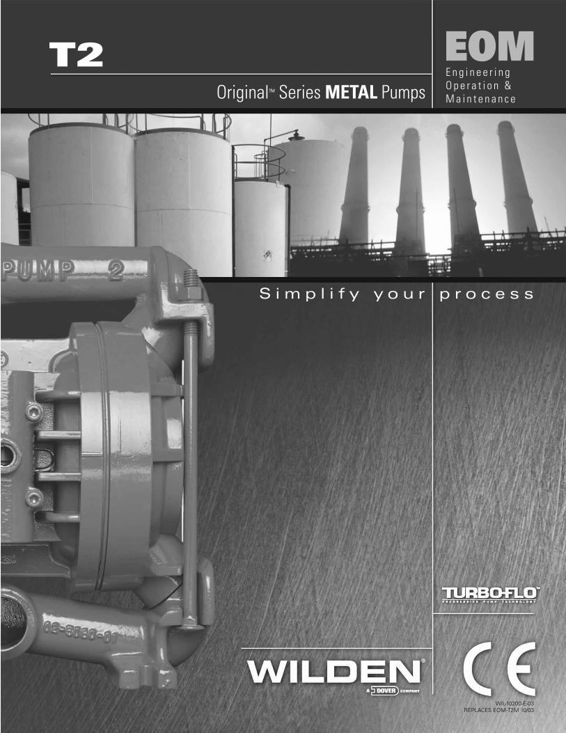
T2
WIL-10200-E-03REPLACES EOM-T2M 10/03
EOM
S i m p l i f y y o u r p r o c e s s
E n g i n e e r i n g O p e r a t i o n &M a i n t e n a n c eOriginal™ Series METAL Pumps
TABLE OF CONTENTSPAGE #
SECTION 1 — CAUTIONS ............................................................................................ 1
SECTION 2 — PUMP DESIGNATION SYSTEM......................................... 2
SECTION 3 — HOW IT WORKS (PUMP & AIR SYSTEMS) ............ 3
SECTION 4 — DIMENSIONAL DRAWINGS A. T2 METAL & T2 UL METAL ............................................................................................... 4
B. T2 METAL SANIFLOFDA ........................................................................................................ 5
SECTION 5 — PERFORMANCE CURVES A. T2 METAL Rubber-Fitted ................................................................................................... 6
B. T2 METAL TPE-Fitted ........................................................................................................ 6
C. T2 METAL PTFE-Fitted ...................................................................................................... 7
SECTION 6 — SUCTION LIFT CURVES & DATA .................................... 7
SECTION 7 — INSTALLATION AND OPERATION A. Installation .......................................................................................................................... 8
B. Operation & Maintenance .................................................................................................. 9
C. Troubleshooting Pumps ..................................................................................................... 10
SECTION 8 — DIRECTIONS FOR DISASSEMBLY/REASSEMBLY A. T2 METAL – Disassembly, Cleaning, Inspection ............................................................... 11
B. Turbo-Flo™ Pump Air Valve/Center Section – Disassembly, Cleaning, Inspection ......... 13
C. Reassembly Hints & Tips ................................................................................................... 14
SECTION 9 — EXPLODED VIEW/PARTS LISTING A. T2 METAL Rubber/TPE-Fitted ........................................................................................... 16
B. T2 METAL PTFE-Fitted ...................................................................................................... 18
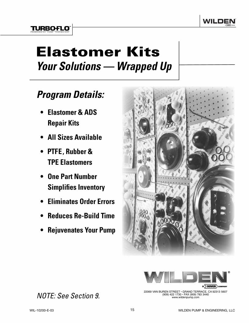
SECTION 10 — ELASTOMER OPTIONS ......................................................... 20
Cla
ss
I &II Ozone
Depleting Substanc
esNON
USEU.S. Clean Air Act
Amendments of 1990
1WIL-10200-E-03 WILDEN PUMP & ENGINEERING, LLC
SECTION 1
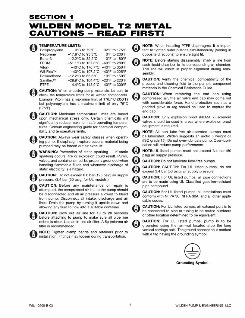
WILDEN MODEL T2 METALCAUTIONS – READ FIRST!
TEMPERATURE LIMITS: Polypropylene 0°C to 79°C 32°F to 175°F Neoprene –17.8°C to 93.3°C 0°F to 200°F Buna-N –12.2°C to 82.2°C 10°F to 180°F EPDM –51.1°C to 137.8°C –60°F to 280°F Viton® –40°C to 176.7°C –40°F to 350°F Wil-Flex™ –40°C to 107.2°C –40°F to 225°F Polyurethane –12.2°C to 65.6°C 10°F to 150°F Saniflex™ –28.9°C to 104.4°C –20°F to 220°F PTFE 4.4°C to 148.9°C 40°F to 300°F
CAUTION: When choosing pump materials, be sure to check the temperature limits for all wetted components. Example: Viton® has a maximum limit of 176.7°C (350°F) but polypropylene has a maximum limit of only 79°C (175°F).
CAUTION: Maximum temperature limits are based upon mechanical stress only. Certain chemicals will significantly reduce maximum safe operating tempera-tures. Consult engineering guide for chemical compat-ibility and temperature limits.
CAUTION: Always wear safety glasses when operat-ing pump. If diaphragm rupture occurs, material being pumped may be forced out air exhaust.
WARNING: Prevention of static sparking — If static sparking occurs, fire or explosion could result. Pump, valves, and containers must be properly grounded when handling flammable fluids and whenever discharge of static electricity is a hazard.
CAUTION: Do not exceed 8.6 bar (125 psig) air supply pressure. (3.4 bar [50 psig] for UL models.)
CAUTION: Before any maintenance or repair is attempted, the compressed air line to the pump should be disconnected and all air pressure allowed to bleed from pump. Disconnect all intake, discharge and air lines. Drain the pump by turning it upside down and allowing any fluid to flow into a suitable container.
CAUTION: Blow out air line for 10 to 20 seconds before attaching to pump to make sure all pipe line debris is clear. Use an in-line air filter. A 5µ (micron) air filter is recommended.
NOTE: Tighten clamp bands and retainers prior to installation. Fittings may loosen during transportation.
NOTE: When installing PTFE diaphragms, it is impor-tant to tighten outer pistons simultaneously (turning in opposite directions) to ensure tight fit.
NOTE: Before starting disassembly, mark a line from each liquid chamber to its corresponding air chamber. This line will assist in proper alignment during reas-sembly.
CAUTION: Verify the chemical compatibility of the process and cleaning fluid to the pump’s component materials in the Chemical Resistance Guide.
CAUTION: When removing the end cap using compressed air, the air valve end cap may come out with considerable force. Hand protection such as a padded glove or rag should be used to capture the end cap.
CAUTION: Only explosion proof (NEMA 7) solenoid valves should be used in areas where explosion proof equipment is required.
NOTE: All non lube-free air-operated pumps must be lubricated. Wilden suggests an arctic 5 weight oil (ISO grade 15). Do not over-lubricate pump. Over-lubri-cation will reduce pump performance.
NOTE: UL-listed pumps must not exceed 3.4 bar (50 psig) air supply pressure.
CAUTION: Do not lubricate lube-free pumps.
CAUTION: CAUTION: For UL listed pumps, do not exceed 3.4 bar (50 psig) air supply pressure.
CAUTION: For UL listed pumps, all pipe connections are to be made using UL Classified gasoline-resistant pipe compound.
CAUTION: For UL listed pumps, all installations must conform with NFPA 30, NFPA 30A, and all other appli-cable codes.
CAUTION: For UL listed pumps, air exhaust port is to be connected to pipe or tubing to be routed outdoors or other location determined to be equivalent.
CAUTION: For UL listed pumps, pump is to be grounded using the jam-nut located atop the long vertical carriage bolt. The ground connection is marked with a tag having the grounding symbol.
Grounding Symbol
2WILDEN PUMP & ENGINEERING, LLC WIL-10200-E-03
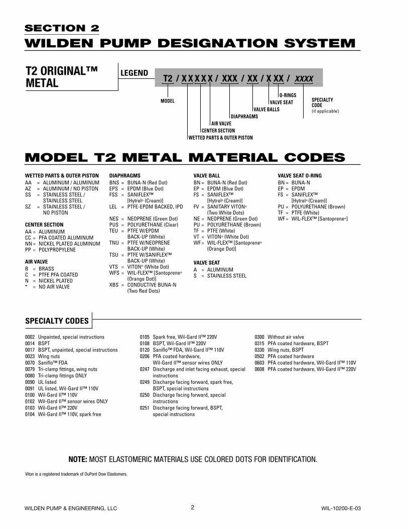
MODEL T2 METAL MATERIAL CODES
SECTION 2
WILDEN PUMP DESIGNATION SYSTEM
NOTE: MOST ELASTOMERIC MATERIALS USE COLORED DOTS FOR IDENTIFICATION.
Viton is a registered trademark of DuPont Dow Elastomers.
*O-RINGS NOT REQUIRED.
WETTED PARTS & OUTER PISTONAA = ALUMINUM / ALUMINUMAZ = ALUMINUM / NO PISTONSS = STAINLESS STEEL /
STAINLESS STEELSZ = STAINLESS STEEL /
NO PISTON
CENTER SECTIONAA = ALUMINUMCC = PFA COATED ALUMINUMNN = NICKEL PLATED ALUMINUMPP = POLYPROPYLENE
AIR VALVEB = BRASSC = PTFE PFA COATED N = NICKEL PLATED * = NO AIR VALVE
DIAPHRAGMSBNS = BUNA-N (Red Dot)EPS = EPDM (Blue Dot)FSS = SANIFLEX™
[Hytrel® (Cream)]LEL = PTFE-EPDM BACKED, IPD
NES = NEOPRENE (Green Dot)PUS = POLYURETHANE (Clear)TEU = PTFE W/EPDM BACK-UP (White)TNU = PTFE W/NEOPRENE BACK-UP (White)TSU = PTFE W/SANIFLEX™
BACK-UP (White)VTS = VITON® (White Dot)WFS = WIL-FLEX™ [Santoprene®
(Orange Dot)]XBS = CONDUCTIVE BUNA-N
(Two Red Dots)
VALVE BALLBN = BUNA-N (Red Dot)EP = EPDM (Blue Dot)FS = SANIFLEX™
[Hytrel® (Cream)]FV = SANITARY VITON®
(Two White Dots)NE = NEOPRENE (Green Dot)PU = POLYURETHANE (Brown)TF = PTFE (White)VT = VITON® (White Dot)WF = WIL-FLEX™ [Santoprene®
(Orange Dot)]
VALVE SEATA = ALUMINUMS = STAINLESS STEEL
VALVE SEAT O-RINGBN = BUNA-NEP = EPDMFS = SANIFLEX™
[Hytrel® (Cream)]PU = POLYURETHANE (Brown)TF = PTFE (White)WF = WIL-FLEX™ [Santoprene®]
LEGENDT2 / X X X X X / XXX / XX / X XX / XXXX
O-RINGSMODEL VALVE SEAT
VALVE BALLSDIAPHRAGMS
AIR VALVECENTER SECTION
WETTED PARTS & OUTER PISTON
SPECIALTYCODE(if applicable)
SPECIALTY CODES
0002 Unpainted, special instructions0014 BSPT0017 BSPT, unpainted, special instructions0023 Wing nuts0070 Saniflo™ FDA0079 Tri-clamp fittings, wing nuts0080 Tri-clamp fittings ONLY0090 UL listed0091 UL listed, Wil-Gard II™ 110V0100 Wil-Gard II™ 110V0102 Wil-Gard II™ sensor wires ONLY0103 Wil-Gard II™ 220V0104 Wil-Gard II™ 110V, spark free
0105 Spark free, Wil-Gard II™ 220V0108 BSPT, Wil-Gard II™ 220V0120 Saniflo™ FDA, Wil-Gard II™ 110V0206 PFA coated hardware,
Wil-Gard II™ sensor wires ONLY0247 Discharge and inlet facing exhaust, special
instructions0249 Discharge facing forward, spark free,
BSPT, special instructions0250 Discharge facing forward, special
instructions0251 Discharge facing forward, BSPT,
special instructions
0300 Without air valve0315 PFA coated hardware, BSPT0330 Wing nuts, BSPT0502 PFA coated hardware0603 PFA coated hardware, Wil-Gard II™ 110V0608 PFA coated hardware, Wil-Gard II™ 220V
T2 ORIGINAL™ METAL
3
SECTION 3
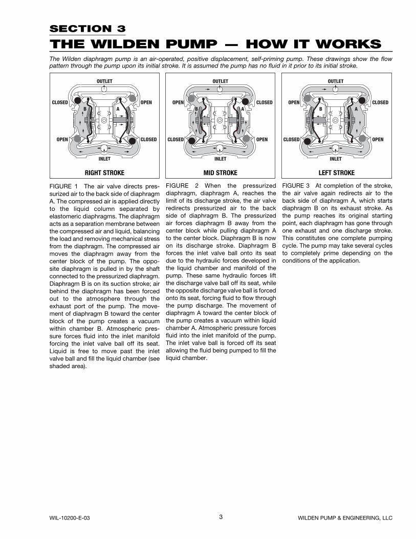
THE WILDEN PUMP — HOW IT WORKSThe Wilden diaphragm pump is an air-operated, positive displacement, self-priming pump. These drawings show the flow pattern through the pump upon its initial stroke. It is assumed the pump has no fluid in it prior to its initial stroke.
FIGURE 1 The air valve directs pres-surized air to the back side of diaphragm A. The compressed air is applied directly to the liquid column separated by elastomeric diaphragms. The diaphragm acts as a separation membrane between the compressed air and liquid, balancing the load and removing mechanical stressfrom the diaphragm. The compressed air moves the diaphragm away from the center block of the pump. The oppo-site diaphragm is pulled in by the shaft connected to the pressurized diaphragm.Diaphragm B is on its suction stroke; air behind the diaphragm has been forced out to the atmosphere through the exhaust port of the pump. The move-ment of diaphragm B toward the center block of the pump creates a vacuum within chamber B. Atmospheric pres-sure forces fluid into the inlet manifold forcing the inlet valve ball off its seat. Liquid is free to move past the inlet valve ball and fill the liquid chamber (see shaded area).
FIGURE 2 When the pressurized diaphragm, diaphragm A, reaches the limit of its discharge stroke, the air valve redirects pressurized air to the back side of diaphragm B. The pressurized air forces diaphragm B away from the center block while pulling diaphragm A to the center block. Diaphragm B is now on its discharge stroke. Diaphragm B forces the inlet valve ball onto its seat due to the hydraulic forces developed in the liquid chamber and manifold of the pump. These same hydraulic forces lift the discharge valve ball off its seat, while the opposite discharge valve ball is forced onto its seat, forcing fluid to flow through the pump discharge. The movement of diaphragm A toward the center block of the pump creates a vacuum within liquid chamber A. Atmospheric pressure forces fluid into the inlet manifold of the pump. The inlet valve ball is forced off its seat allowing the fluid being pumped to fill the liquid chamber.
FIGURE 3 At completion of the stroke, the air valve again redirects air to the back side of diaphragm A, which starts diaphragm B on its exhaust stroke. As the pump reaches its original starting point, each diaphragm has gone through one exhaust and one discharge stroke. This constitutes one complete pumping cycle. The pump may take several cycles to completely prime depending on the conditions of the application.
RIGHT STROKE MID STROKE LEFT STROKE
WIL-10200-E-03 WILDEN PUMP & ENGINEERING, LLC
4
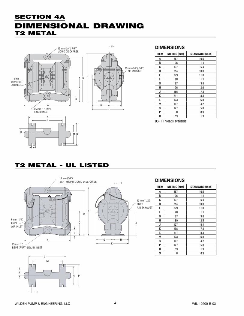
SECTION 4A
DIMENSIONAL DRAWINGT2 METAL
F
A
B
C
DE
G H
J
K
L
M
N P
S
R
25 mm (1")BSPT (FNPT) LIQUID INLET
19 mm (3/4")BSPT (FNPT) LIQUID DISCHARGE
13 mm (1/2")FNPTAIR EXHAUST
6 mm (1/4")FNPTAIR INLET
DIMENSIONS
ITEM METRIC (mm) STANDARD (inch)
A 267 10.5B 36 1.4C 137 5.4D 254 10.0E 279 11.0F 28 1.1G 97 3.8H 76 3.0J 185 7.3K 211 8.3L 173 6.8M 107 4.2N 127 5.0P 8 0.3R 33 1.3
DIMENSIONS
ITEM METRIC (mm) STANDARD (inch)
A 267 10.5B 36 1.4C 137 5.4D 254 10.0E 279 11.0F 28 1.1G 97 3.8H 89 3.5J 137 5.4K 198 7.8L 211 8.3M 173 6.8N 107 4.2P 127 5.0R 33 1.3S 8 0.3
T2 METAL - UL LISTED
WILDEN PUMP & ENGINEERING, LLC WIL-10200-E-03
BSPT Threads available
5
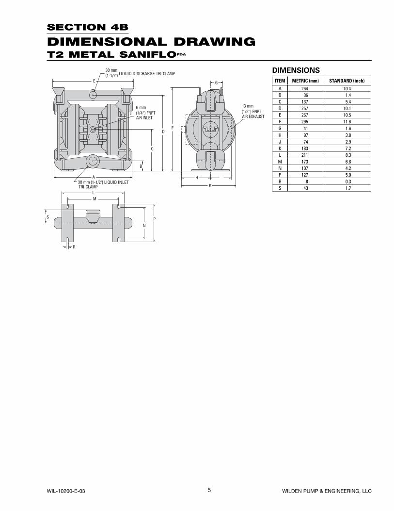
SECTION 4B
DIMENSIONAL DRAWING
DIMENSIONS
ITEM METRIC (mm) STANDARD (inch)
A 264 10.4B 36 1.4C 137 5.4D 257 10.1E 267 10.5F 295 11.6G 41 1.6H 97 3.8J 74 2.9K 183 7.2L 211 8.3M 173 6.8N 107 4.2P 127 5.0R 8 0.3S 43 1.7
T2 METAL SANIFLOFDA
WIL-10200-E-03 WILDEN PUMP & ENGINEERING, LLC
6
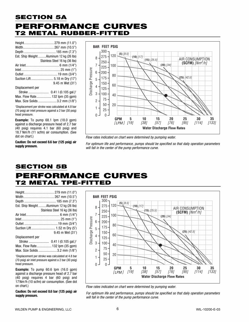
Height .................................. 279 mm (11.0”)Width ................................... 267 mm (10.5”)Depth .................................... 185 mm (7.3”)Est. Ship Weight .........Aluminum 12 kg (26 lbs)
Stainless Steel 16 kg (36 lbs)Air Inlet ......................................6 mm (1/4”)Inlet ............................................ 25 mm (1”)Outlet ......................................19 mm (3/4”)Suction Lift ......................... 5.18 m Dry (17’)
9.45 m Wet (31’)Displacement per Stroke ....................... 0.41 l (0.105 gal.)1
Max. Flow Rate ................. 132 lpm (35 gpm)Max. Size Solids .....................3.2 mm (1/8”)1Displacement per stroke was calculated at 4.8 bar (70 psig) air inlet pressure against a 2 bar (30 psig) head pressure.
Example: To pump 68.1 lpm (18.0 gpm) against a discharge pressure head of 2.7 bar (40 psig) requires 4.1 bar (60 psig) and 18.7 Nm3/h (11 scfm) air consumption. (See dot on chart.)
Caution: Do not exceed 8.6 bar (125 psig) air supply pressure.
Flow rates indicated on chart were determined by pumping water.
For optimum life and performance, pumps should be specified so that daily operation parameters will fall in the center of the pump performance curve.
Height .................................. 279 mm (11.0”)Width ................................... 267 mm (10.5”)Depth .................................... 185 mm (7.3”)Est. Ship Weight .........Aluminum 12 kg (26 lbs)
Stainless Steel 16 kg (36 lbs)Air Inlet ...................................... 6 mm (1/4”)Inlet ............................................ 25 mm (1”)Outlet ......................................19 mm (3/4”)Suction Lift ........................... 1.52 m Dry (5’)
9.45 m Wet (31’)Displacement per Stroke ....................... 0.41 l (0.105 gal.)1
Max. Flow Rate ................. 132 lpm (35 gpm)Max. Size Solids .....................3.2 mm (1/8”)1Displacement per stroke was calculated at 4.8 bar (70 psig) air inlet pressure against a 2 bar (30 psig) head pressure.
Example: To pump 60.6 lpm (16.0 gpm) against a discharge pressure head of 2.7 bar (40 psig) requires 4 bar (60 psig) and17 Nm3/h (10 scfm) air consumption. (See dot on chart.)
Caution: Do not exceed 8.6 bar (125 psig) air supply pressure.
Flow rates indicated on chart were determined by pumping water.
For optimum life and performance, pumps should be specified so that daily operation parameters will fall in the center of the pump performance curve.
SECTION 5B
PERFORMANCE CURVES
SECTION 5A
PERFORMANCE CURVEST2 METAL RUBBER-FITTED
T2 METAL TPE-FITTED
WILDEN PUMP & ENGINEERING, LLC WIL-10200-E-03
7
Height .................................. 279 mm (11.0”)Width ................................... 267 mm (10.5”)Depth .................................... 185 mm (7.3”)Est. Ship Weight .........Aluminum 12 kg (26 lbs)
Stainless Steel 16 kg (36 lbs)Air Inlet ...................................... 6 mm (1/4”)Inlet ............................................ 25 mm (1”)Outlet ......................................19 mm (3/4”)Suction Lift ........................... 1.83 m Dry (6’)
9.45 m Wet (31’)Displacement per Stroke ....................... 0.19 l (0.050 gal.)1
Max. Flow Rate ................... 95 lpm (25 gpm)Max. Size Solids .....................3.2 mm (1/8”)1Displacement per stroke was calculated at 4.8 bar (70 psig) air inlet pressure against a 2 bar (30 psig) head pressure.
Example: To pump 45.4 lpm (12.0 gpm) against a discharge pressure head of 2.7 bar (40 psig) requires 4.1 bar (60 psig) and22.1 Nm3/h (13 scfm) air consumption. (See dot on chart.)
Caution: Do not exceed 8.6 bar (125 psig) air supply pressure.
Flow rates indicated on chart were determined by pumping water.
For optimum life and performance, pumps should be specified so that daily operation parameters will fall in the center of the pump performance curve.
SECTION 6
SUCTION LIFT CURVES
Suction lift curves are calibrated for pumps operating at 305 m (1,000’) above sea level. This chart is meant to be a guide only. There are many variables which can affect your pump’s operating characteristics. The number of intake
and discharge elbows, viscosity of pumping fluid, elevation (atmospheric pressure) and pipe friction loss all affect the amount of suction lift your pump will attain.
SECTION 5C
PERFORMANCE CURVEST2 METAL PTFE-FITTED
WIL-10200-E-03 WILDEN PUMP & ENGINEERING, LLC
8
SECTION 7A
INSTALLATIONThe Model T2 Metal pump has a 25 mm (1”) inlet and 19 mm (3/4”) outlet and is designed for flows to 132 lpm (35 gpm). The T2 Metal pump is manufactured with wetted parts of aluminum or stainless steel. The center section of the T2 Metal pump is of aluminum or polypropylene construction. The air distribution system consists of a brass air valve body, aluminum air valve piston, Glyd™ rings and a bronze center section bushing. A variety of diaphragms, valve balls, valve seats, and o-rings are available to satisfy temperature, chemical compatibility, abrasion and flex concerns.
The suction pipe size should be at least 25 mm (1”) diam-eter or larger if highly viscous material is being pumped. The suction hose must be non-collapsible, reinforced type as the T2 is capable of pulling a high vacuum. Discharge piping should be at least 19 mm (3/4”); larger diameter can be used to reduce friction losses. It is critical that all fittings and connections are airtight or a reduction or loss of pump suction capability will result.
INSTALLATION: Months of careful planning, study, and selection efforts can result in unsatisfactory pump perfor-mance if installation details are left to chance.
Premature failure and long term dissatisfaction can be avoided if reasonable care is exercised throughout the installation process.
LOCATION: Noise, safety, and other logistical factors usually dictate that “utility” equipment be situated away from the production floor. Multiple installations with conflicting requirements can result in congestion of utility areas, leaving few choices for siting of additional pumps.
Within the framework of these and other existing conditions, every pump should be located in such a way that four key factors are balanced against each other to maximum advan-tage.
1. ACCESS: First of all, the location should be accessible. If it’s easy to reach the pump, maintenance personnel will have an easier time carrying out routine inspections and adjustments. Should major repairs become necessary, ease of access can play a key role in speeding the repair process and reducing total downtime.
2. AIR SUPPLY: Every pump location should have an air line large enough to supply the volume of air necessary to achieve the desired pumping rate (see pump performance chart). Use air pressure up to a maximum of 8.6 bar (125 psig) depend-ing upon pumping requirements. The use of an air filter before the pump will ensure that the majority of any pipeline contaminants will be eliminated. For best results, the pumps should use an air filter, regulator, and lubricator system.
3. ELEVATION: Selecting a site that is well within the pump’s suction lift capability will assure that loss-of-prime trou-bles will be eliminated. In addition, pump efficiency can be adversely affected if proper attention is not given to elevation (see pump performance chart).
4. PIPING: Final determination of the pump site should not be made until the piping problems of each possible loca-tion have been evaluated. The impact of current and future installations should be considered ahead of time to make sure that inadvertent restrictions are not created for any remaining sites.
For UL listed pumps, all installations must conform with NFPA 30, NFPA 30A, and all other applicable codes. All pipe connections are to be made using UL Classified gasoline-resistant pipe compound. Exhaust port is to be connected to pipe or tubing to be routed outdoors or other location determined to be equivalent
The best choice possible will be a site involving the shortest and the straightest hook-up of suction and discharge piping. Unnecessary elbows, bends, and fittings should be avoided. Pipe sizes should be selected so as to keep friction losses within practical limits. All piping should be supported inde-pendently of the pump. In addition, it should line up without placing stress on the pump fittings.
Expansion joints can be installed to aid in absorbing the forces created by the natural reciprocating action of the pump. If the pump is to be bolted down to a solid foundation, a mounting pad placed between the pump and foundation will assist in minimizing pump vibration. Flexible connections between the pump and rigid piping will also assist in mini-mizing pump vibration. If quick-closing valves are installed at any point in the discharge system, or if pulsation within a system becomes a problem, a surge suppressor should be installed to protect the pump, piping and gauges from surges and water hammer.
When pumps are installed in applications involving flooded suction or suction head pressures, a gate valve should be installed in the suction line to permit closing of the line for pump service.
The T2 can be used in submersible applications only when both wetted and non-wetted portions are com patible with the material being pumped. If the pump is to be used in a submersible application, a hose should be attached to the pump’s air exhaust and the exhaust air piped above the liquid level.
If the pump is to be used in a self-priming application, be sure that all connections are airtight and that the suction lift is within the pump’s ability. Note: Materials of construction and elastomer material have an effect on suction lift param-eters. Please refer to pump performance data.
Pumps in service with a positive suction head are most effi-cient when inlet pressure is limited to 0.5–0.7 bar (7–10 psig). Premature diaphragm failure may occur if positive suction is 0.8 bar (11 psig) and higher.
THE MODEL T2 WILL PASS 3.2 mm (1/8”) SOLIDS. WHEN-EVER THE POSSIBILITY EXISTS THAT LARGER SOLID OBJECTS MAY BE SUCKED INTO THE PUMP, A STRAINER SHOULD BE USED ON THE SUCTION LINE.
CAUTION: DO NOT EXCEED 8.6 BAR (125 PSIG) AIR SUPPLY PRESSURE. (3.4 BAR [50 PSIG] FOR UL MODELS.)
BLOW OUT AIR LINE FOR 10 TO 20 SECONDS BEFORE ATTACHING TO PUMP TO MAKE SURE ALL PIPE LINE DEBRIS IS CLEAR. ALWAYS USE AN IN-LINE AIR FILTER.
WILDEN PUMP & ENGINEERING, LLC WIL-10200-E-03
9
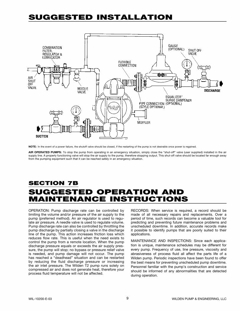
SUGGESTED INSTALLATION
SECTION 7B
SUGGESTED OPERATION ANDMAINTENANCE INSTRUCTIONSOPERATION: Pump discharge rate can be controlled by limiting the volume and/or pressure of the air supply to the pump (preferred method). An air regulator is used to regu-late air pressure. A needle valve is used to regulate volume. Pump discharge rate can also be controlled by throttling the pump discharge by partially closing a valve in the discharge line of the pump. This action increases friction loss which reduces flow rate. This is useful when the need exists to control the pump from a remote location. When the pump discharge pressure equals or exceeds the air supply pres-sure, the pump will stop; no bypass or pressure relief valve is needed, and pump damage will not occur. The pump has reached a “deadhead” situation and can be restarted by reducing the fluid discharge pressure or increasing the air inlet pressure. The Wilden T2 pump runs solely on compressed air and does not generate heat, therefore your process fluid temperature will not be affected.
RECORDS: When service is required, a record should be made of all necessary repairs and replacements. Over a period of time, such records can become a valuable tool for predicting and preventing future maintenance problems and unscheduled downtime. In addition, accurate records make it possible to identify pumps that are poorly suited to their applications.
MAINTENANCE AND INSPECTIONS: Since each applica-tion is unique, maintenance schedules may be different for every pump. Frequency of use, line pressure, viscosity and abrasiveness of process fluid all affect the parts life of a Wilden pump. Periodic inspections have been found to offer the best means for preventing unscheduled pump downtime. Personnel familiar with the pump’s construction and service should be informed of any abnormalities that are detected during operation.
NOTE: In the event of a power failure, the shutoff valve should be closed, if the restarting of the pump is not desirable once power is regained.
AIR OPERATED PUMPS: To stop the pump from operating in an emergency situation, simply close the “shut-off” valve (user supplied) installed in the air supply line. A properly functioning valve will stop the air supply to the pump, therefore stopping output. This shut-off valve should be located far enough away from the pumping equipment such that it can be reached safely in an emergency situation.
WIL-10200-E-03 WILDEN PUMP & ENGINEERING, LLC
10
SECTION 7C – AIR OPERATION
TROUBLESHOOTINGPump will not run or runs slowly.1. Check air inlet screen and air filter for debris.2. Check for sticking air valve, flush air valve in solvent.3. Check for worn out air valve. If piston face in air valve is
shiny instead of dull, air valve is probably worn beyond working tolerances and must be replaced.
4. Check center block Glyd™ rings. If worn excessively, they will not seal and air will simply flow through pump and out air exhaust. Use only Wilden Glyd™ rings as they are of special construction.
5. Check for rotating piston in air valve.6. Check type of lubricant being used. A higher viscosity
oil than suggested may cause the piston to stick or run erratically. Wilden suggests the use of an oil with arctic characteristics (ISO 15-5 wt.).
Pump runs but little or no product flows.1. Check for pump cavitation; slow pump speed down to
match thickness of material being pumped.
2. Check for sticking ball check valves. If material being pumped is not compatible with pump elastomers, swell-ing may occur. Replace ball check valves and o-rings with the proper elastomers.
3. Check to make sure all suction connections are air tight, especially clamp bands around intake balls.
Pump air valve freezes.Check for excessive moisture in compressed air. Either install dryer or hot air generator for compressed air.
Air bubbles in pump discharge.1. Check for ruptured diaphragm.2. Check tightness of clamp bands, especially at intake mani-
fold.
Product comes out air exhaust.1. Check for diaphragm rupture.2. Check tightness of piston plates to shaft.
WILDEN PUMP & ENGINEERING, LLC WIL-10200-E-03
11
SECTION 8A
T2 METALDIRECTIONS FOR DISASSEMBLY/REASSEMBLY
Figure 1
Step 2. Figure 2
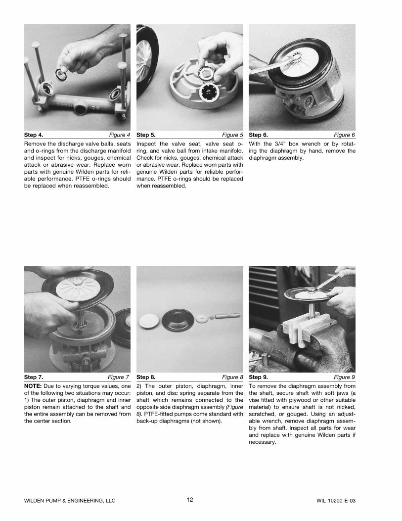
Utilizing the 9/16” box wrench, start by removing the four long carriage bolts that secure the top and bottom manifolds to the center section.
Step 3. Figure 3
Remove the top manifold and lift the center section off the inlet manifold.
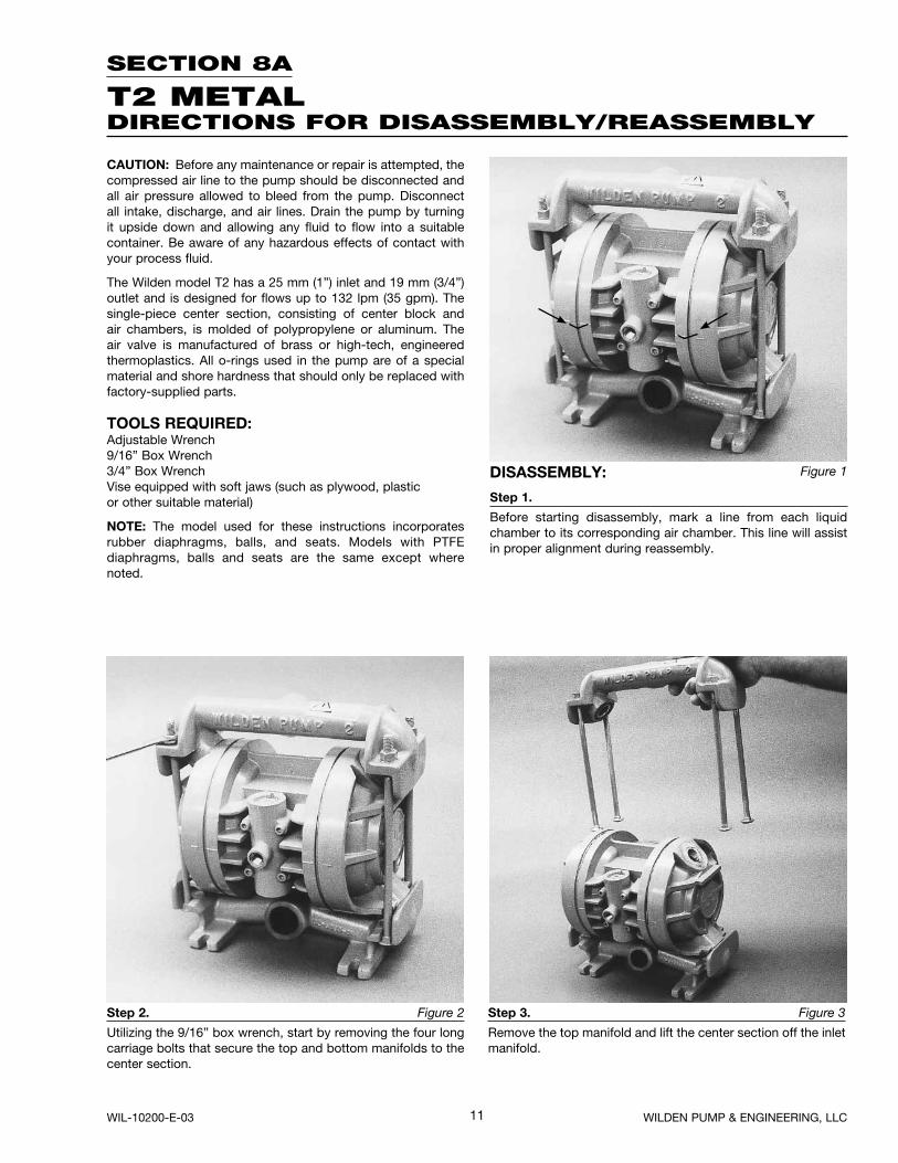
CAUTION: Before any maintenance or repair is attempted, the compressed air line to the pump should be disconnected and all air pressure allowed to bleed from the pump. Disconnect all intake, discharge, and air lines. Drain the pump by turning it upside down and allowing any fluid to flow into a suitable container. Be aware of any hazardous effects of contact with your process fluid.
The Wilden model T2 has a 25 mm (1”) inlet and 19 mm (3/4”) outlet and is designed for flows up to 132 lpm (35 gpm). The single-piece center section, consisting of center block and air chambers, is molded of polypropylene or aluminum. The air valve is manufactured of brass or high-tech, engineered thermoplastics. All o-rings used in the pump are of a special material and shore hardness that should only be replaced with factory-supplied parts.
TOOLS REQUIRED:Adjustable Wrench9/16” Box Wrench3/4” Box WrenchVise equipped with soft jaws (such as plywood, plasticor other suitable material)
NOTE: The model used for these instructions incorporates rubber diaphragms, balls, and seats. Models with PTFE diaphragms, balls and seats are the same except where noted.
DISASSEMBLY:
Step 1.
Before starting disassembly, mark a line from each liquid chamber to its corresponding air chamber. This line will assist in proper alignment during reassembly.
WIL-10200-E-03 WILDEN PUMP & ENGINEERING, LLC
12
Step 7. Figure 7
NOTE: Due to varying torque values, one of the following two situations may occur: 1) The outer piston, diaphragm and inner piston remain attached to the shaft and the entire assembly can be removed from the center section.
Step 8. Figure 8
2) The outer piston, diaphragm, inner piston, and disc spring separate from the shaft which remains connected to the opposite side diaphragm assembly (Figure8). PTFE-fitted pumps come standard with back-up diaphragms (not shown).
Step 9. Figure 9
To remove the diaphragm assembly from the shaft, secure shaft with soft jaws (a vise fitted with plywood or other suitable material) to ensure shaft is not nicked, scratched, or gouged. Using an adjust-able wrench, remove diaphragm assem-bly from shaft. Inspect all parts for wear and replace with genuine Wilden parts if necessary.
Step 4. Figure 4
Remove the discharge valve balls, seats and o-rings from the discharge manifold and inspect for nicks, gouges, chemical attack or abrasive wear. Replace worn parts with genuine Wilden parts for reli-able performance. PTFE o-rings should be replaced when reassembled.
Step 5. Figure 5
Inspect the valve seat, valve seat o-ring, and valve ball from intake manifold. Check for nicks, gouges, chemical attack or abrasive wear. Replace worn parts with genuine Wilden parts for reliable perfor-mance. PTFE o-rings should be replaced when reassembled.
Step 6. Figure 6
With the 3/4” box wrench or by rotat-ing the diaphragm by hand, remove the diaphragm assembly.
WILDEN PUMP & ENGINEERING, LLC WIL-10200-E-03
13
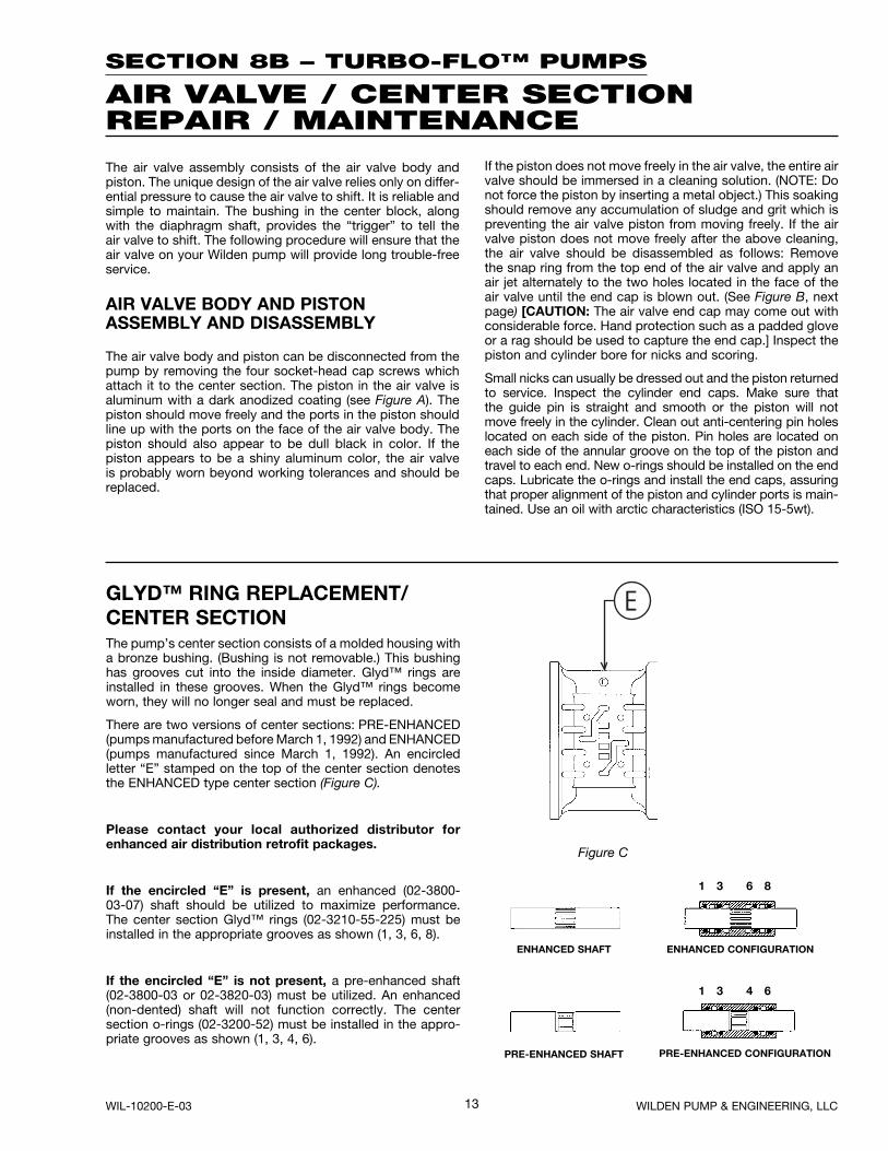
GLYD™ RING REPLACEMENT/CENTER SECTIONThe pump’s center section consists of a molded housing with a bronze bushing. (Bushing is not removable.) This bushing has grooves cut into the inside diameter. Glyd™ rings are installed in these grooves. When the Glyd™ rings become worn, they will no longer seal and must be replaced.
There are two versions of center sections: PRE-ENHANCED (pumps manufactured before March 1, 1992) and ENHANCED (pumps manufactured since March 1, 1992). An encircled letter “E” stamped on the top of the center section denotes the ENHANCED type center section (Figure C).
Please contact your local authorized distributor for enhanced air distribution retrofit packages.
If the encircled “E” is present, an enhanced (02-3800-03-07) shaft should be utilized to maximize performance. The center section Glyd™ rings (02-3210-55-225) must be installed in the appropriate grooves as shown (1, 3, 6, 8).
If the encircled “E” is not present, a pre-enhanced shaft(02-3800-03 or 02-3820-03) must be utilized. An enhanced (non-dented) shaft will not function correctly. The centersection o-rings (02-3200-52) must be installed in the appro-priate grooves as shown (1, 3, 4, 6).
1 3 6 8
ENHANCED CONFIGURATIONENHANCED SHAFT
1 3 4 6
PRE-ENHANCED CONFIGURATIONPRE-ENHANCED SHAFT
Figure C
The air valve assembly consists of the air valve body and piston. The unique design of the air valve relies only on differ-ential pressure to cause the air valve to shift. It is reliable and simple to maintain. The bushing in the center block, along with the diaphragm shaft, provides the “trigger” to tell the air valve to shift. The following procedure will ensure that the air valve on your Wilden pump will provide long trouble-free service.
AIR VALVE BODY AND PISTONASSEMBLY AND DISASSEMBLY
The air valve body and piston can be disconnected from the pump by removing the four socket-head cap screws which attach it to the center section. The piston in the air valve is aluminum with a dark anodized coating (see Figure A). The piston should move freely and the ports in the piston should line up with the ports on the face of the air valve body. The piston should also appear to be dull black in color. If the piston appears to be a shiny aluminum color, the air valve is probably worn beyond working tolerances and should be replaced.
If the piston does not move freely in the air valve, the entire air valve should be immersed in a cleaning solution. (NOTE: Do not force the piston by inserting a metal object.) This soaking should remove any accumulation of sludge and grit which is preventing the air valve piston from moving freely. If the air valve piston does not move freely after the above cleaning, the air valve should be disassembled as follows: Remove the snap ring from the top end of the air valve and apply an air jet alternately to the two holes located in the face of the air valve until the end cap is blown out. (See Figure B, next page) [CAUTION: The air valve end cap may come out with considerable force. Hand protection such as a padded glove or a rag should be used to capture the end cap.] Inspect the piston and cylinder bore for nicks and scoring.
Small nicks can usually be dressed out and the piston returned to service. Inspect the cylinder end caps. Make sure that the guide pin is straight and smooth or the piston will not move freely in the cylinder. Clean out anti-centering pin holes located on each side of the piston. Pin holes are located on each side of the annular groove on the top of the piston and travel to each end. New o-rings should be installed on the end caps. Lubricate the o-rings and install the end caps, assuring that proper alignment of the piston and cylinder ports is main-tained. Use an oil with arctic characteristics (ISO 15-5wt).
SECTION 8B – TURBO-FLO™ PUMPS
AIR VALVE / CENTER SECTIONREPAIR / MAINTENANCE
WIL-10200-E-03 WILDEN PUMP & ENGINEERING, LLC
14
SECTION 8C
REASSEMBLY HINTS & TIPSASSEMBLY:Upon performing applicable maintenance to the air distribu-tion system, the pump can now be reassembled. Please refer to the disassembly instructions for photos and parts placement. To reassemble the pump, follow the disassem-bly instructions in reverse order. The air distribution system needs to be assembled first, then the diaphragms and finally the wetted path. Please find the applicable torque speci-fications on this page. The following tips will assist in the assembly process.
• Clean the inside of the center section shaft bushing to ensure no damage is done to new seals.
• Stainless bolts should be lubed to reduce the possibility of seizing during tightening.
• Level the water chamber side of the intake/discharge manifold to ensure a proper sealing surface. This is most easily accomplished by placing them on a flat surface prior to tightening their clamp bands to the desired torque (see this page for torque specs).
• Be sure to tighten outer pistons simultaneously on PTFE-fitted pumps to ensure proper torque values.
• Place one liquid chamber on its side and align center section with chamber using alignment marks made during disassembly. Push down on diaphragm assembly until diaphragm is inverted. Place opposite liquid chamber on center section and align.
• Position valve balls, seats, and o-rings in discharge manifold. Place vertical through discharge manifold with threads pointing up. Install washer and start threads of bolt (about 1-1/2 turns).
• Place center section and liquid chambers on intake mani-fold.
• Position discharge manifold and bolt assembly on liquid chambers. Ensure proper alignment of mating surfaces between liquid chambers and manifolds before tightening bolts.
• Apply a small amount of Loctite 242 to the steel bore of the shaft from the diaphragm assembly.
UL LISTED PUMPSASSEMBLY:
Upon performing applicable maintenance to the air distribu-tion system, the UL pump can now be reassembled. Please refer to the disassembly instructions for photos and parts placement. To reassemble the pump, follow the disassem-bly instructions in reverse order. The air distribution system needs to be assembled first, then the diaphragms and finally the wetted path. Please find the applicable torque speci-fications on this page. The following tips will assist in the assembly process.
• Clean the inside of the center section shaft bushing to ensure no damage is done to new seals.
• Stainless steel bolts should be lubed to reduce the possi-bility of seizing during tightening.
• Level the water chamber side of the intake/discharge manifold to ensure a proper sealing surface. This is most easily accomplished by placing them on a flat surface prior to tightening their vertical bolts to the desired torque.
• Apply a small amount of Loctite 242 to the steel bore of the shaft from the diaphragm assembly.
• Be sure to tighten outer pistons simultaneously on PTFE-fitted pumps to ensure proper torque values.
• Place one liquid chamber on its side and align center section with chamber using alignment marks made during disassembly. Push down on diaphragm assembly until diaphragm is inverted. Place opposite liquid cham-ber on center section and align.
• Position valve balls, seats, and o-rings in discharge mani-fold. Install vertical bolts through discharge manifold with threads pointing up. Install washer and start threads of bolt (about 11 turns).
• Place center section and liquid chambers on intake manifold.
• Position discharge manifold and bolt assembly on liquid chambers. Ensure proper alignment of mating surfaces between liquid chambers and manifolds before tighten-ing vertical bolts.
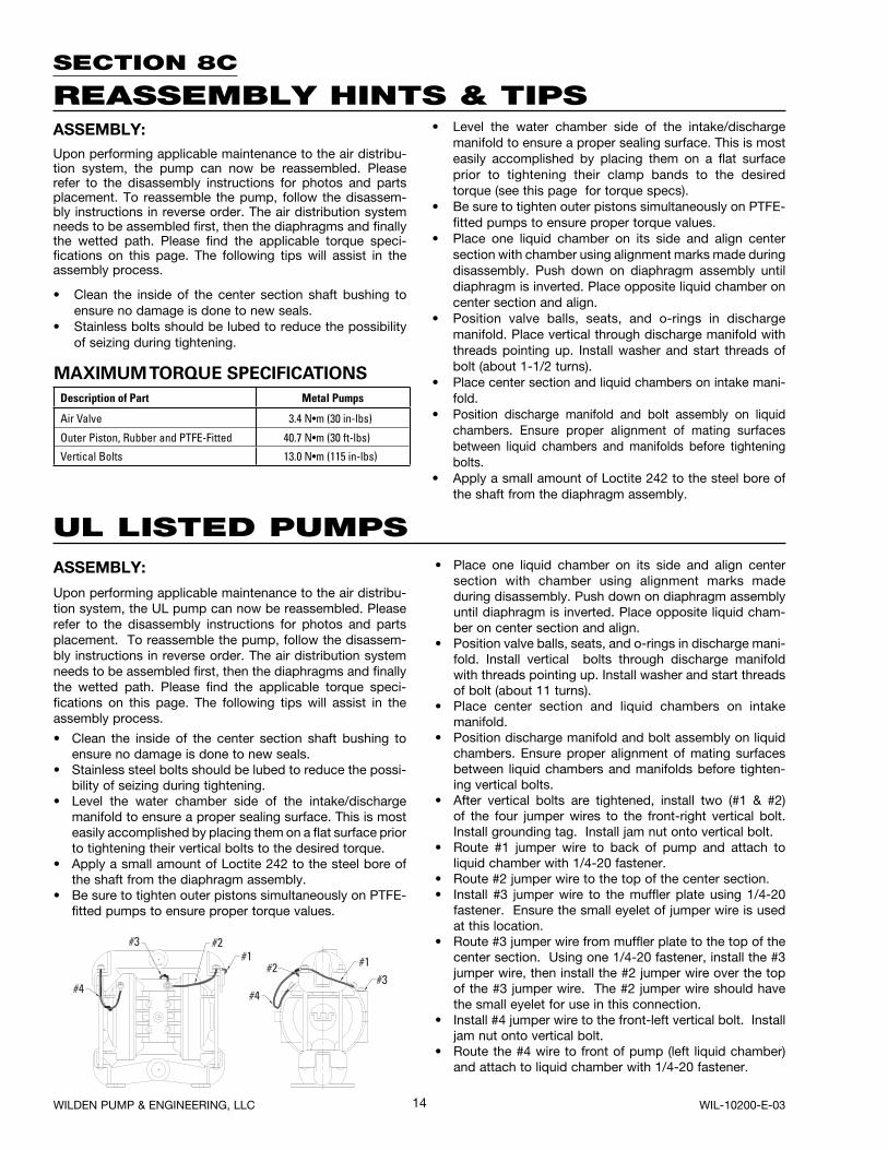
• After vertical bolts are tightened, install two (#1 & #2) of the four jumper wires to the front-right vertical bolt. Install grounding tag. Install jam nut onto vertical bolt.
• Route #1 jumper wire to back of pump and attach to liquid chamber with 1/4-20 fastener.
• Route #2 jumper wire to the top of the center section.• Install #3 jumper wire to the muffler plate using 1/4-20
fastener. Ensure the small eyelet of jumper wire is used at this location.
• Route #3 jumper wire from muffler plate to the top of the center section. Using one 1/4-20 fastener, install the #3 jumper wire, then install the #2 jumper wire over the top of the #3 jumper wire. The #2 jumper wire should have the small eyelet for use in this connection.
• Install #4 jumper wire to the front-left vertical bolt. Install jam nut onto vertical bolt.
• Route the #4 wire to front of pump (left liquid chamber) and attach to liquid chamber with 1/4-20 fastener.
MAXIMUM TORQUE SPECIFICATIONS
Description of Part Metal Pumps
Air Valve 3.4 N•m (30 in-lbs)
Outer Piston, Rubber and PTFE-Fitted 40.7 N•m (30 ft-lbs)
Vertical Bolts 13.0 N•m (115 in-lbs)
WILDEN PUMP & ENGINEERING, LLC WIL-10200-E-03
15WIL-10200-E-03 WILDEN PUMP & ENGINEERING, LLC
16
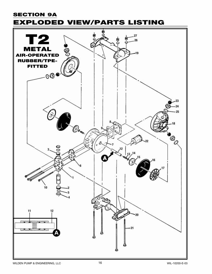
SECTION 9A
EXPLODED VIEW/PARTS LISTING
T2METAL
AIR-OPERATEDRUBBER/TPE-
FITTED
WILDEN PUMP & ENGINEERING, LLC WIL-10200-E-03
17
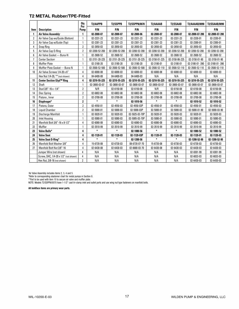
T2 METAL Rubber/TPE-Fitted
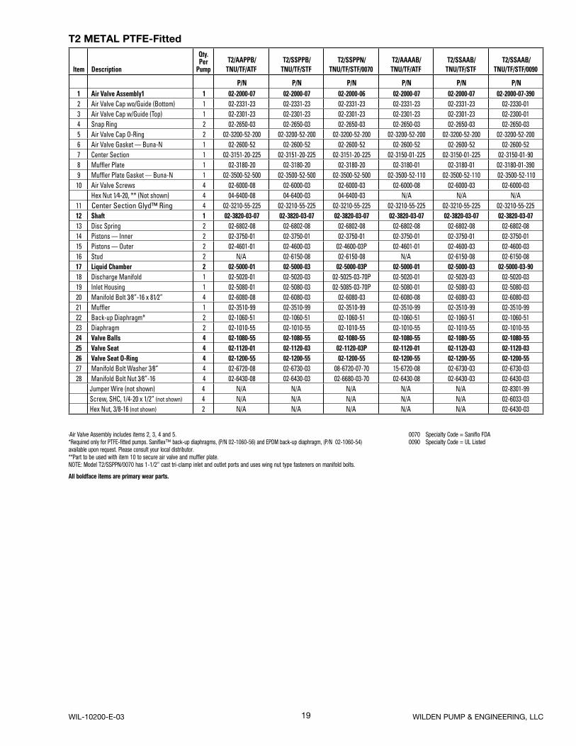
1Air Valve Assembly includes items 2, 3, 4 and 5.*Refer to corresponding elastomer chart for metal pumps in Section 8.**Part to be used with item 10 to secure air valve and muffler plate.NOTE: Models T2/SSPPN/0070 have 1-1/2” cast tri-clamp inlet and outlet ports and use wing nut type fasteners on manifold bolts.
All boldface items are primary wear parts.
Item Description
Qty. Per
Pump
T2/AAPPB T2/SSPPB T2/SSPPN/0070 T2/AAAAB T2/SSAAB T2/AAAAB/0090 T2/SSAAB/0090
P/N P/N P/N P/N P/N P/N P/N 1 Air Valve Assembly1 1 02-2000-07 02-2000-07 02-2000-06 02-2000-07 02-2000-07 02-2000-07-390 02-2000-07-390 2 Air Valve Cap wo/Guide (Bottom) 1 02-2331-23 02-2331-23 02-2331-23 02-2331-23 02-2331-23 02-2330-01 02-2330-01 3 Air Valve Cap w/Guide (Top) 1 02-2301-23 02-2301-23 02-2301-23 02-2301-23 02-2301-23 02-2300-01 02-2300-01 4 Snap Ring 2 02-2650-03 02-2650-03 02-2650-03 02-2650-03 02-2650-03 02-2650-03 02-2650-03 5 Air Valve Cap O-Ring 2 02-3200-52-200 02-3200-52-200 02-3200-52-200 02-3200-52-200 02-3200-52-200 02-3200-52-200 02-3200-52-200 6 Air Valve Gasket — Buna-N 1 02-2600-52 02-2600-52 02-2600-52 02-2600-52 02-2600-52 02-2600-52 02-2600-52 7 Center Section1 1 02-3151-20-225 02-3151-20-225 02-3151-20-225 02-3150-01-225 02-3150-06-225 02-3150-01-90 02-3150-01-90 8 Muffler Plate 1 02-3180-20 02-3180-20 02-3180-20 02-3180-01 02-3180-01 02-3180-01 -390 02-3180-01 -390 9 Muffler Plate Gasket — Buna-N 1 02-3500-52-500 02-3500-52-500 02-3500-52-500 02-3500-52-110 02-3500-52-110 02-3500-52-110 02-3500-52-110
10 Air Valve Screws 1/4-20 x 6” 4 02-6000-08 02-6000-03 02-6000-03 02-6000-08 02-6000-03 02-6000-03 02-6000-03 Hex Nut 1/4-20, ** (not nhown) 4 04-6400-08 04-6400-03 04-6400-03 N/A N/A N/A N/A
11 Center Section Glyd™ Ring 4 02-3210-55-225 02-3210-55-225 02-3210-55-225 02-3210-55-225 02-3210-55-225 02-3210-55-225 02-3210-55-225 12 Shaft 1 02-3800-03-07 02-3800-03-07 02-3800-03-07 02-3800-03-07 02-3800-03-07 02-3800-03-07 02-3800-03-07 13 Stud 3/8”-16 x -1/4” 2 N/R 02-6150-08 02-6150-08 N/R 02-6150-08 02-6150-08 02-6150-08 14 Disc Spring 2 02-6802-08 02-6802-08 02-6802-08 02-6802-08 02-6802-08 02-6802-08 02-6802-08 15 Pistons , Inner 2 02-3700-08 02-3700-08 02-3700-08 02-3700-08 02-3700-08 02-3700-08 02-3700-08 16 Diaphragm* 2 * * 02-1010-56 * * 02-1010-52 02-1010-52 17 Pistons, Outer 2 02-4550-01 02-4550-03 02-4550-03P 02-4550-01 02-4550-03 02-4550-01 02-4550-03 18 Liquid Chamber 2 02-5000-01 02-5000-03 02-5000-03P 02-5000-01 02-5000-03 02-5000-01-90 02-5000-03-90 19 Discharge Manifold 1 02-5020-01 02-5020-03 02-5025-03-70P 02-5020-01 02-5020-03 02-5020-01 02-5020-03 20 Inlet Housing 1 02-5080-01 02-5080-03 02-5085-03-70P 02-5080-01 02-5080-03 02-5080-01 02-5080-03 21 Manifold Bolt 3/6”-16 x 8-1/2” 4 02-6080-08 02-6080-03 02-6080-03 02-6080-08 02-6080-03 02-6080-03 02-6080-03 22 Muffl er 1 02-3510-99 02-3510-99 02-3510-99 02-3510-99 02-3510-99 02-3510-99 02-3510-99 23 Valve Balls* 4 * * 02-1080-56 * * 02-1080-52 02-1080-52 24 Valve Seat 4 02-1120-01 02-1120-03 02-1120-03P 02-1120-01 02-1120-03 02-1120-01 02-1120-03 25 Valve Seat O-Ring* 4 * * 02-1200-56 * * 02-1200-52-90 02-1200-52-90 26 Manifold Bolt Washer 3/8” 4 15-6720-08 02-6730-03 08-6720-07-70 15-6720-08 02-6730-03 02-6730-03 02-6730-03 27 Manifold Bolt Nut 3/8”-16 4 02-6430-08 02-6430-03 02-6680-03-70 02-6430-08 02-6430-03 02-6430-03 02-6430-03
Jumper Wire (not shown) 4 N/A N/A N/A N/A N/A 02-8301-99 02-8301-99Screw, SHC, 1/4-20 x 1/2” (not shown) 4 N/A N/A N/A N/A N/A 02-6033-03 02-6033-03Hex Nut, 3/8-16 (not shown) 2 N/A N/A N/A N/A N/A 02-6430-03 02-6430-03
WIL-10200-E-03 WILDEN PUMP & ENGINEERING, LLC
18
27
26
17
23
24
25
16
20
21
22
18
19
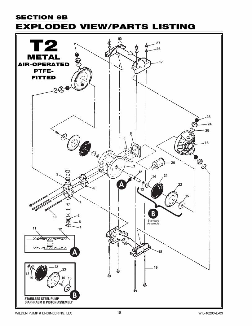
SECTION 9B
EXPLODED VIEW/PARTS LISTING
T2METAL
AIR-OPERATEDPTFE-
FITTED
WILDEN PUMP & ENGINEERING, LLC WIL-10200-E-03
19
T2 METAL PTFE-Fitted
1Air Valve Assembly includes items 2, 3, 4 and 5.*Required only for PTFE-fitted pumps. Saniflex™ back-up diaphragms, (P/N 02-1060-56) and EPDM back-up diaphragm, (P/N 02-1060-54)available upon request. Please consult your local distributor.**Part to be used with item 10 to secure air valve and muffler plate.NOTE: Model T2/SSPPN/0070 has 1-1/2” cast tri-clamp inlet and outlet ports and uses wing nut type fasteners on manifold bolts.
All boldface items are primary wear parts.
0070 Specialty Code = Saniflo FDA0090 Specialty Code = UL Listed
Item Description
Qty. Per
Pump T2/AAPPB/TNU/TF/ATF
T2/SSPPB/TNU/TF/STF
T2/SSPPN/TNU/TF/STF/0070
T2/AAAAB/TNU/TF/ATF
T2/SSAAB/TNU/TF/STF
T2/SSAAB/TNU/TF/STF/0090
P/N P/N P/N P/N P/N P/N 1 Air Valve Assembly1 1 02-2000-07 02-2000-07 02-2000-06 02-2000-07 02-2000-07 02-2000-07-390 2 Air Valve Cap wo/Guide (Bottom) 1 02-2331-23 02-2331-23 02-2331-23 02-2331-23 02-2331-23 02-2330-01 3 Air Valve Cap w/Guide (Top) 1 02-2301-23 02-2301-23 02-2301-23 02-2301-23 02-2301-23 02-2300-01 4 Snap Ring 2 02-2650-03 02-2650-03 02-2650-03 02-2650-03 02-2650-03 02-2650-03 5 Air Valve Cap O-Ring 2 02-3200-52-200 02-3200-52-200 02-3200-52-200 02-3200-52-200 02-3200-52-200 02-3200-52-200 6 Air Valve Gasket — Buna-N 1 02-2600-52 02-2600-52 02-2600-52 02-2600-52 02-2600-52 02-2600-52 7 Center Section 1 02-3151-20-225 02-3151-20-225 02-3151-20-225 02-3150-01-225 02-3150-01-225 02-3150-01-90 8 Muffler Plate 1 02-3180-20 02-3180-20 02-3180-20 02-3180-01 02-3180-01 02-3180-01-390 9 Muffler Plate Gasket — Buna-N 1 02-3500-52-500 02-3500-52-500 02-3500-52-500 02-3500-52-110 02-3500-52-110 02-3500-52-110
10 Air Valve Screws 4 02-6000-08 02-6000-03 02-6000-03 02-6000-08 02-6000-03 02-6000-03 Hex Nut 1⁄4-20, ** (Not shown) 4 04-6400-08 04-6400-03 04-6400-03 N/A N/A N/A
11 Center Section Glyd™ Ring 4 02-3210-55-225 02-3210-55-225 02-3210-55-225 02-3210-55-225 02-3210-55-225 02-3210-55-225 12 Shaft 1 02-3820-03-07 02-3820-03-07 02-3820-03-07 02-3820-03-07 02-3820-03-07 02-3820-03-07 13 Disc Spring 2 02-6802-08 02-6802-08 02-6802-08 02-6802-08 02-6802-08 02-6802-08 14 Pistons — Inner 2 02-3750-01 02-3750-01 02-3750-01 02-3750-01 02-3750-01 02-3750-01 15 Pistons — Outer 2 02-4601-01 02-4600-03 02-4600-03P 02-4601-01 02-4600-03 02-4600-03 16 Stud 2 N/A 02-6150-08 02-6150-08 N/A 02-6150-08 02-6150-08 17 Liquid Chamber 2 02-5000-01 02-5000-03 02-5000-03P 02-5000-01 02-5000-03 02-5000-03-90 18 Discharge Manifold 1 02-5020-01 02-5020-03 02-5025-03-70P 02-5020-01 02-5020-03 02-5020-03 19 Inlet Housing 1 02-5080-01 02-5080-03 02-5085-03-70P 02-5080-01 02-5080-03 02-5080-03 20 Manifold Bolt 3⁄8”-16 x 81⁄2” 4 02-6080-08 02-6080-03 02-6080-03 02-6080-08 02-6080-03 02-6080-03 21 Muffler 1 02-3510-99 02-3510-99 02-3510-99 02-3510-99 02-3510-99 02-3510-99 22 Back-up Diaphragm* 2 02-1060-51 02-1060-51 02-1060-51 02-1060-51 02-1060-51 02-1060-51 23 Diaphragm 2 02-1010-55 02-1010-55 02-1010-55 02-1010-55 02-1010-55 02-1010-55 24 Valve Balls 4 02-1080-55 02-1080-55 02-1080-55 02-1080-55 02-1080-55 02-1080-55 25 Valve Seat 4 02-1120-01 02-1120-03 02-1120-03P 02-1120-01 02-1120-03 02-1120-03 26 Valve Seat O-Ring 4 02-1200-55 02-1200-55 02-1200-55 02-1200-55 02-1200-55 02-1200-55 27 Manifold Bolt Washer 3⁄8” 4 02-6720-08 02-6730-03 08-6720-07-70 15-6720-08 02-6730-03 02-6730-03 28 Manifold Bolt Nut 3⁄8”-16 4 02-6430-08 02-6430-03 02-6680-03-70 02-6430-08 02-6430-03 02-6430-03
Jumper Wire (not shown) 4 N/A N/A N/A N/A N/A 02-8301-99Screw, SHC, 1/4-20 x 1/2” (not shown) 4 N/A N/A N/A N/A N/A 02-6033-03Hex Nut, 3/8-16 (not shown) 2 N/A N/A N/A N/A N/A 02-6430-03
WIL-10200-E-03 WILDEN PUMP & ENGINEERING, LLC
20
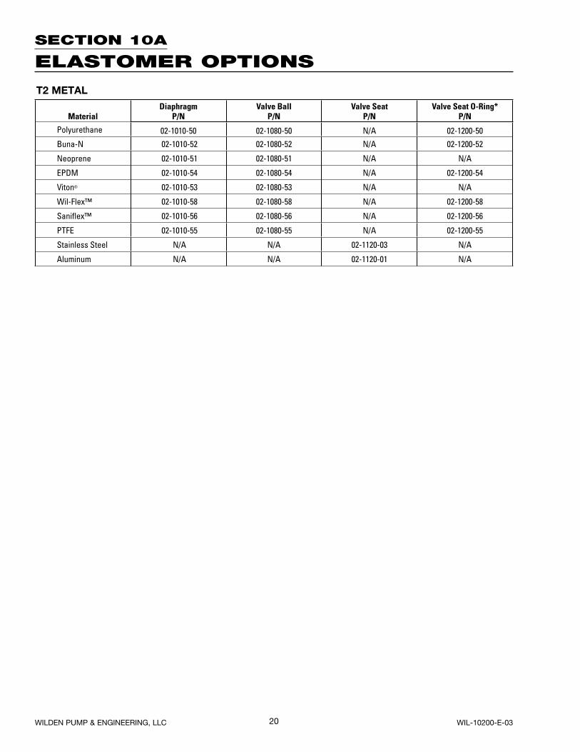
SECTION 10A
ELASTOMER OPTIONS
T2 METAL
MaterialDiaphragm
P/NValve Ball
P/NValve Seat
P/NValve Seat O-Ring*
P/N
Polyurethane 02-1010-50 02-1080-50 N/A 02-1200-50
Buna-N 02-1010-52 02-1080-52 N/A 02-1200-52
Neoprene 02-1010-51 02-1080-51 N/A N/A
EPDM 02-1010-54 02-1080-54 N/A 02-1200-54
Viton® 02-1010-53 02-1080-53 N/A N/A
Wil-Flex™ 02-1010-58 02-1080-58 N/A 02-1200-58
Sanifl ex™ 02-1010-56 02-1080-56 N/A 02-1200-56
PTFE 02-1010-55 02-1080-55 N/A 02-1200-55
Stainless Steel N/A N/A 02-1120-03 N/A
Aluminum N/A N/A 02-1120-01 N/A
WILDEN PUMP & ENGINEERING, LLC WIL-10200-E-03

Item # Serial #
Company Where Purchased
Company Name
Industry
Name Title
Street Address
City State Postal Code Country
Telephone Fax E-mail Web Address
Number of pumps in facility? Number of Wilden pumps?
Types of pumps in facility (check all that apply): Diaphragm Centrifugal Gear Submersible Lobe
Other
Media being pumped?
How did you hear of Wilden Pump? Trade Journal Trade Show Internet/E-mail Distributor
Other
P U M P I N F O R M AT I O N
PLEASE PRINT OR TYPE AND FAX TO WILDEN
YO U R I N F O R M AT I O N
ONCE COMPLETE, FAX TO (909) 783-3440
NOTE: WARRANTY VOID IF PAGE IS NOT FAXED TO WILDEN
WILDEN PUMP & ENGINEERING, LLC
W A R R A N T YEach and every product manufactured by Wilden Pump and Engineering, LLC is built to meet the highest standards of quality. Every pump is functionally tested to insure integrity of operation.
Wilden Pump and Engineering, LLC warrants that pumps, accessories and parts manufactured or supplied by it to be free from defects in material and workmanship for a period of five (5) years from date of installation or six (6) years from date of manufacture, whichever comes first. Failure due to normal wear, misapplication, or abuse is, of course, excluded from this warranty.
Since the use of Wilden pumps and parts is beyond our control, we cannot guarantee the suitability of any pump or part for a particular application and Wilden Pump and Engineering, LLC shall not be liable for any consequential damage or expense arising from the use or misuse of its products on any application. Responsibility is limited solely to replacement or repair of defective Wilden pumps and parts.
All decisions as to the cause of failure are the sole determination of Wilden Pump and Engineering, LLC.
Prior approval must be obtained from Wilden for return of any items for warranty consideration and must be accompanied by the appropriate MSDS for the product(s) involved. A Return Goods Tag, obtained from an authorized Wilden distributor, must be included with the items which must be shipped freight prepaid.
The foregoing warranty is exclusive and in lieu of all other warranties expressed or implied (whether written or oral) including all implied warranties of merchantability and fitness for any particular purpose. No distributor or other person is authorized to assume any liability or obligation for Wilden Pump and Engineering, LLC other than expressly provided herein.