what's new in powermill 9 9 whats_new.pdf · what's new in powermill 9.0 summary of new...
TRANSCRIPT

What's New in
PowerMILL 9.0
By Delcam plc
Beta Issue 1

Disclaimer Delcam plc has no control over the use made of the software described in this manual and cannot accept responsibility for any loss or damage howsoever caused as a result of using the software. Users are advised that all the results from the software should be checked by a competent person, in accordance with good quality control procedures. Information contained in this manual is subject to change without notice and does not represent a commitment by Delcam plc. The software described in this manual is furnished under licence agreement and may be used or copied in accordance with the terms of such licence. No part of this manual may be reproduced or transmitted in any form or by any means, electronic or mechanical, including photocopying and recording, for any purpose without the express permission of Delcam plc. Copyright © 1996-2008 Delcam plc. All rights reserved Acknowledgements This documentation references a number of registered trademarks and these are the property of their respective owners. For example, Microsoft and Windows are either registered trademarks or trademarks of Microsoft Corporation in the United States and/or other countries. Patents The Raceline smoothing functionality is subject to patent applications.
Patent pending: GB 2374562 Improvements Relating to Machine Tools Patent granted: US 6,832,876 Machine Tools
Some of the functionality of the ViewMill and Simulation modules of PowerMILL is subject to patent applications.
Patent granted: GB 2 423 592 Surface Finish Prediction Licenses Intelligent cursor licensed under U.S. patent numbers 5,123,087 and 5,371,845 (Ashlar Inc.)
PowerMILL 9.0 Date: 10/07/2008 11:27
What's New in PowerMILL 9.0 Contents • i
Contents
Summary of new features 1
Toolpath preparation intro .............................................................................1 Toolpath generation .......................................................................................2 Toolpath verification......................................................................................3 Toolpath output..............................................................................................3 User interface .................................................................................................3 General ...........................................................................................................3 Preview ..........................................................................................................3
Toolpath preparation 4
Curve Editor toolbar ......................................................................................4 Collect Curves .......................................................................................9 Selection...............................................................................................11 Limit to Point .......................................................................................13 Join straight example ...........................................................................16 Join tangent example ...........................................................................18 Join close example ...............................................................................19 Cut curve example ...............................................................................20 Merge selected example ......................................................................22 Curve Fitting ........................................................................................22 Transformations ...................................................................................24 Instrumentation ....................................................................................35 Workplane and Points..........................................................................35 Lines.....................................................................................................41 Circles ..................................................................................................45 Grid ......................................................................................................55 Intelligent Cursor .................................................................................56
Block ............................................................................................................62 Creating a block ...................................................................................62
Pattern ..........................................................................................................64 Blanking.......................................................................................................66
Example using blanking ......................................................................67
ii • Contents What's New in PowerMILL 9.0
General toolpath preparation improvements ...............................................69
Toolpath generation 72
Cutter compensation ....................................................................................72 Applying cutter compensation.............................................................74 Drawing compensated toolpaths..........................................................76 Handling cutter compensation applied in previous versions...............78
New Machining Strategy dialog ..................................................................81 Common toolpath creation controls for new strategies.......................82
Face Milling .............................................................................................. 100 Chamfer Milling - Overview .................................................................... 105
Chamfer Milling ............................................................................... 106 Multiple Cuts .................................................................................... 110 Model Gouge Check ......................................................................... 114
2D Curve Profile ....................................................................................... 116 Curve Profile..................................................................................... 117 Cut Distances .................................................................................... 126 Draft Angle ....................................................................................... 130 Rest Machining................................................................................. 131 Offset ................................................................................................ 132 High Speed........................................................................................ 136 Order ................................................................................................. 143 Approach........................................................................................... 147 Automatic Verification - 2D Curve .................................................. 148
2D Curve Area Clearance ......................................................................... 153 Curve Area Clearance....................................................................... 155 Raster ................................................................................................ 160
Thread Milling .......................................................................................... 161 Expert dialog..................................................................................... 163
What's New in PowerMILL 9.0 Contents • iii
Surface and Surface Projection machining............................................... 166 Swarf machining ....................................................................................... 168 General toolpath improvements................................................................ 169
Toolpath verification 170
Collision Checker...................................................................................... 170
Toolpath output 171
Viewing NC programs .............................................................................. 171 General toolpath output enhancements..................................................... 173
User interface 174
Options dialog........................................................................................... 174 Thickness Shading .................................................................................... 175 Selection Modes........................................................................................ 176
Box Selection.................................................................................... 176 Drag Selection................................................................................... 177
Index 179

What's New in PowerMILL 9.0 Summary of new features • 1
PowerMILL 9.0 offers all the original features of PowerMILL 8.0, but with numerous improvements. This document is still in the process of being written. This is not a complete list of all the improvements. A complete What's New will be available in time for the full release of PowerMILL 9.0. The most significant improvements are:
Toolpath preparation intro There is a new Curve Editor toolbar (see page 4) that allows you to create and edit patterns and boundaries. There are a few improvements to help you to create a Block (see page 62).
You can enter a block length as well as the minimum and maximum values.
The Cylindrical parameters now displays the Diameter rather than the radius.
A new Lock All button enables you to lock all the limits or all the cylindrical parameters in one go.
A new Blanking option (see page 66) on the View menu allows you to temporarily hide selected model components from the screen. There are several General toolpath preparation enhancements (see page 69).
Summary of new features

2 • Summary of new features What's New in PowerMILL 9.0
Toolpath generation Cutter compensation (see page 72) is much improved and can now be applied to all 2.5D machining, area clearance, and drilling strategies when the toolpath is created. Some of the new machining strategies use a New machining strategy dialog (see page 81). This is a tabbed dialog which is simpler to use than the previous huge dialog and provides an easier way to create toolpaths. There is a new Face Milling strategy (see page 100) that produces flat surfaces by guiding a large cutter over the surface of the workpiece. There is a new Chamfer Milling strategy (see page 105) that bevels sharp corners using specific chamfer tools. Chamfer milling is used to break sharp outside-edges of a model after it has been completely machined. There is a new 2D Curve Profile strategy (see page 116) that creates a simple toolpath following one or more curves at a single Z height. This is an easy way to create 2D machining toolpaths. There is a new 2D Curve Area Clearance strategy (see page 153) that creates simple 2.5D raster or offset roughing toolpaths. There is a new drilling cycle of Thread Milling (see page 161). There are two changes to Surface and Surface Projection machining (see page 166):
The stepover is adjusted so that the final cut finishes exactly on the surface edge.
There is a new Spiral option. There are a couple of Swarf machining enhancements:
You can now generate surface swarf toolpaths where the selected surfaces have different component thicknesses.
There are improvements to rulings used for wireframe swarf machining.
You can now create wireframe swarf machining from curves, without a model. This is possible when you don't want to check the toolpath against a model by deselecting Gouge Check.
There are several General toolpath enhancements (see page 169).
What's New in PowerMILL 9.0 Summary of new features • 3
Toolpath verification There are several improvements to Collision Checking.
In many cases collision checking is now faster. The improvements are particularly noticeable on large models.
PowerMILL reports on the depth of a collision and the required tool overhang even if the change needed is very small.
The tool in locked toolpaths can now be replaced during collision checking.
Toolpath output You can now View an NC program (see page 171) from within PowerMILL. When a toolpath using a ball nosed tool is displayed in an NC Program dialog the Tip radius field displays the tool radius value (see page 173).
User interface The Options dialog (see page 174) uses a tree instead as a tabbed dialog. The Shading toolbar (see page 175) has two new boundary shading options. The View toolbar has three new selection modes (see page 176) that allow you to select or deselect different entities in a project.
General No general functionality has been documented in this beta version.
Preview No preview functionality has been documented in this beta version.
Preview features are provided for you to evaluate and should not generally be used for production work. Delcam plc makes no guarantee that the behaviour of preview features will be preserved when (and if) they are released.
4 • Toolpath preparation What's New in PowerMILL 9.0
Curve Editor toolbar The Curve Editor replaces the Sketcher functionality. The sketcher is now only available from the Insert - Sketch on the individual Pattern or Boundary context menu. The Curve Editor toolbar allows you to create and edit patterns and boundaries. The assumption is that you will extract curves from the model, by say, extracting curves at surface boundaries, and then modify the curve to create the exact boundary/pattern you need. The Curve Editor toolbar is only available from an active pattern or boundary.
Click on the Pattern toolbar.
Click on the Boundary toolbar. Edit - Curve Editor, or Insert - Curve Editor on the individual
Pattern context menu. Edit - Curve Editor, or Insert - Curve Editor on the individual
Boundary context menu.
On activating the Curve Editor toolbar most of PowerMILL's functionality is disabled until you exit from curve editing. This includes: the menu bar most toolbars explorer's context menus graphics area's context menus
Toolpath preparation
What's New in PowerMILL 9.0 Toolpath preparation • 5
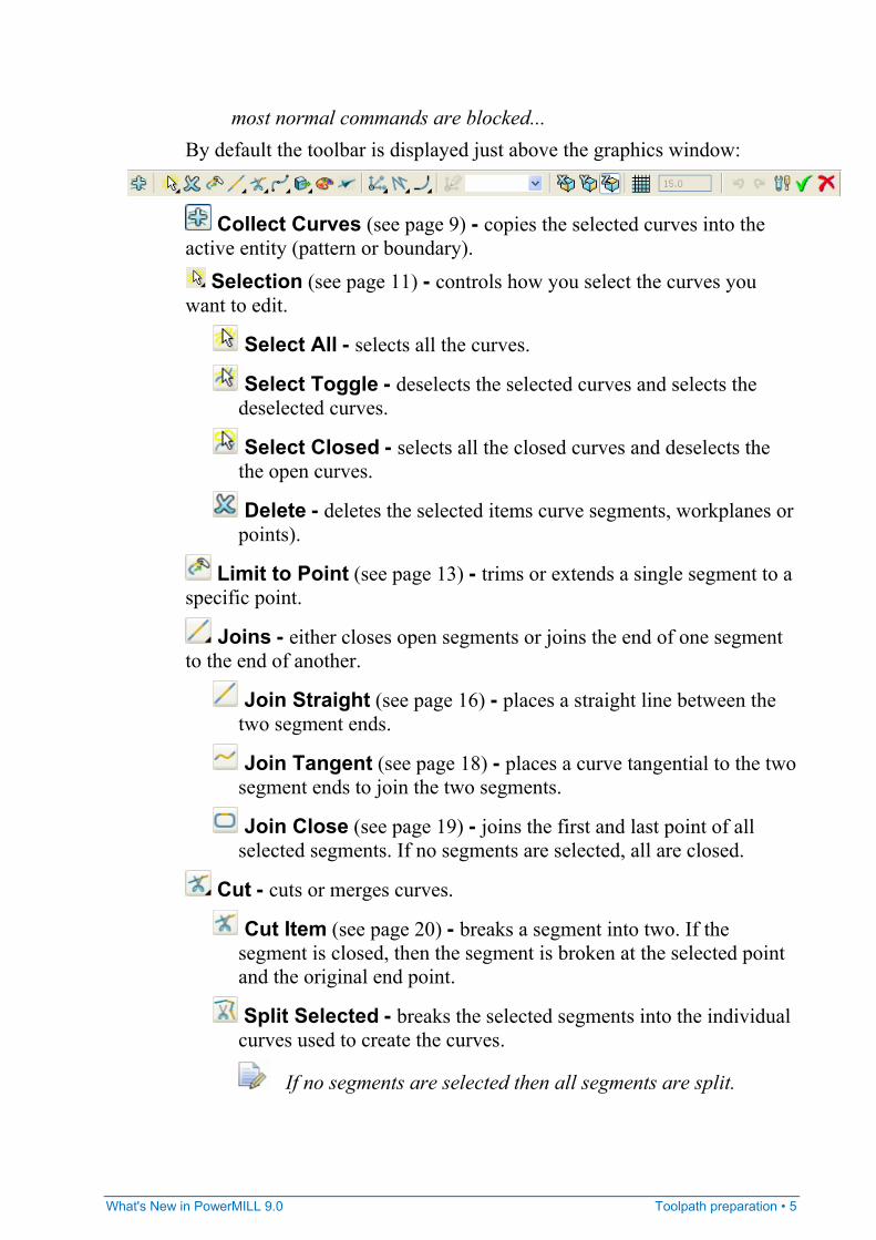
most normal commands are blocked... By default the toolbar is displayed just above the graphics window:
Collect Curves (see page 9) - copies the selected curves into the active entity (pattern or boundary).
Selection (see page 11) - controls how you select the curves you want to edit.
Select All - selects all the curves.
Select Toggle - deselects the selected curves and selects the deselected curves.
Select Closed - selects all the closed curves and deselects the the open curves.
Delete - deletes the selected items curve segments, workplanes or points).
Limit to Point (see page 13) - trims or extends a single segment to a specific point.
Joins - either closes open segments or joins the end of one segment to the end of another.
Join Straight (see page 16) - places a straight line between the two segment ends.
Join Tangent (see page 18) - places a curve tangential to the two segment ends to join the two segments.
Join Close (see page 19) - joins the first and last point of all selected segments. If no segments are selected, all are closed.
Cut - cuts or merges curves.
Cut Item (see page 20) - breaks a segment into two. If the segment is closed, then the segment is broken at the selected point and the original end point.
Split Selected - breaks the selected segments into the individual curves used to create the curves.
If no segments are selected then all segments are split.
6 • Toolpath preparation What's New in PowerMILL 9.0
Merge Selected (see page 22) - merges individual segments into one curve.
Curve Fitting (see page 22) - converts the selected curve segments to a specific type of curve.
Arc Fit Selected - arc fits selected segments. This is used to smooth curves.
Spline Selected - converts the selected segments into a spline.
Polygonise Selected - converts the selected segments to a series of straight lines.
Transformations (see page 24) - allows you to move, rotate, scale or mirror curves. All of the options from the pull-out toolbar display their own individual toolbar.
Move - transforms the curves by the specified coordinates.
Rotate - rotates the curves around the specified axis by the selected angle.
Mirror - mirrors the curves along one of the principal planes of the active workplane or along an arbitrary mirror line. If no workplane is active, the mirroring is about the relevant plane of the global coordinate system.
Scale - scales the model around the specified origin by the specified factor.
Change Segment Colour - changes the colour of the selected segments. This displays a standard Windows colour dialog, selecting a colour here changes the colour of the selected curves. If no segments are selected this option sets the default colour for all new segments.
This only works for patterns and not for boundaries.
Instrumentation (see page 35) - all curves in a pattern have a direction. If you instrument a pattern it will place an arrow on each segment (pointing towards the end of the segment) and an "X" at the end of each segment.
Workplane and Points (see page 35) - creates new workplanes and points. All of the options from the pull-out toolbar display their own individual toolbar.
What's New in PowerMILL 9.0 Toolpath preparation • 7
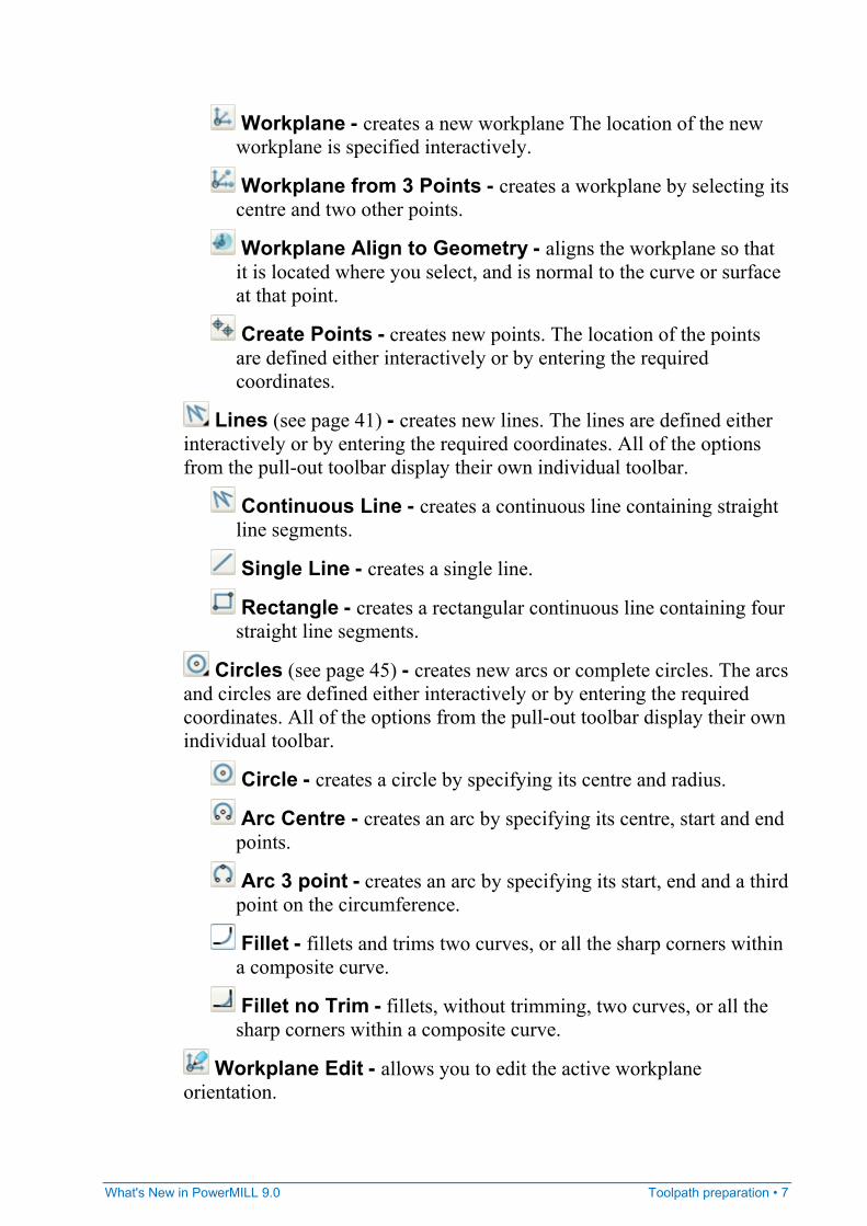
Workplane - creates a new workplane The location of the new workplane is specified interactively.
Workplane from 3 Points - creates a workplane by selecting its centre and two other points.
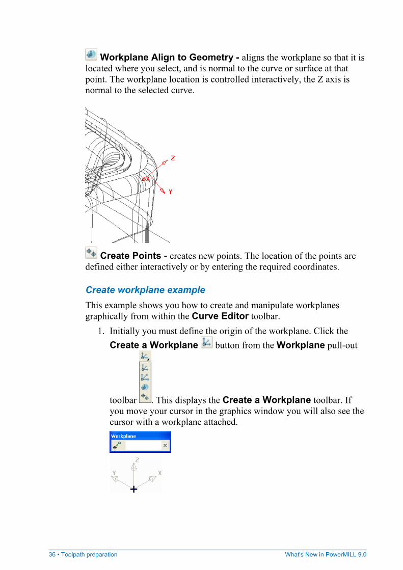
Workplane Align to Geometry - aligns the workplane so that it is located where you select, and is normal to the curve or surface at that point.
Create Points - creates new points. The location of the points are defined either interactively or by entering the required coordinates.
Lines (see page 41) - creates new lines. The lines are defined either interactively or by entering the required coordinates. All of the options from the pull-out toolbar display their own individual toolbar.
Continuous Line - creates a continuous line containing straight line segments.
Single Line - creates a single line.
Rectangle - creates a rectangular continuous line containing four straight line segments.
Circles (see page 45) - creates new arcs or complete circles. The arcs and circles are defined either interactively or by entering the required coordinates. All of the options from the pull-out toolbar display their own individual toolbar.
Circle - creates a circle by specifying its centre and radius.
Arc Centre - creates an arc by specifying its centre, start and end points.
Arc 3 point - creates an arc by specifying its start, end and a third point on the circumference.
Fillet - fillets and trims two curves, or all the sharp corners within a composite curve.
Fillet no Trim - fillets, without trimming, two curves, or all the sharp corners within a composite curve.
Workplane Edit - allows you to edit the active workplane orientation.
8 • Toolpath preparation What's New in PowerMILL 9.0
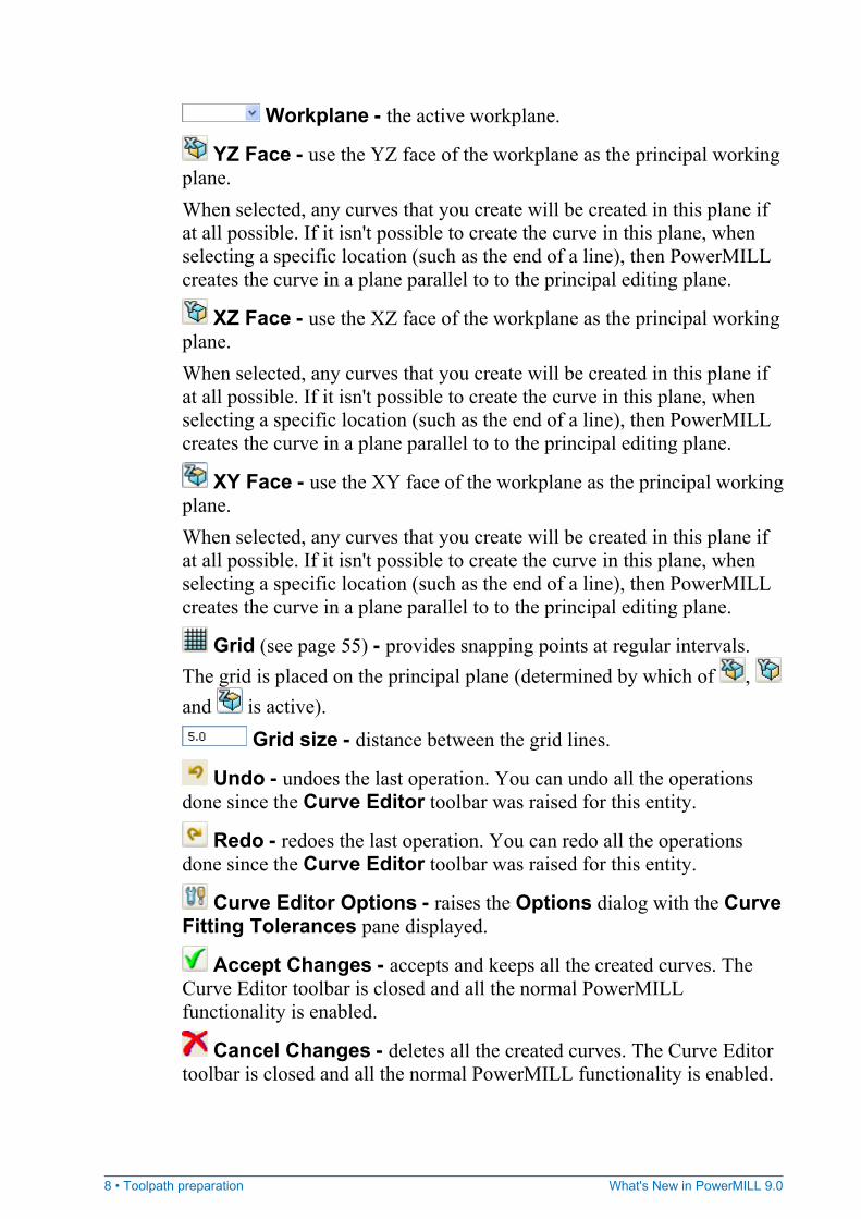
Workplane - the active workplane.
YZ Face - use the YZ face of the workplane as the principal working plane. When selected, any curves that you create will be created in this plane if at all possible. If it isn't possible to create the curve in this plane, when selecting a specific location (such as the end of a line), then PowerMILL creates the curve in a plane parallel to to the principal editing plane.
XZ Face - use the XZ face of the workplane as the principal working plane. When selected, any curves that you create will be created in this plane if at all possible. If it isn't possible to create the curve in this plane, when selecting a specific location (such as the end of a line), then PowerMILL creates the curve in a plane parallel to to the principal editing plane.
XY Face - use the XY face of the workplane as the principal working plane. When selected, any curves that you create will be created in this plane if at all possible. If it isn't possible to create the curve in this plane, when selecting a specific location (such as the end of a line), then PowerMILL creates the curve in a plane parallel to to the principal editing plane.
Grid (see page 55) - provides snapping points at regular intervals. The grid is placed on the principal plane (determined by which of , and is active).
Grid size - distance between the grid lines.
Undo - undoes the last operation. You can undo all the operations done since the Curve Editor toolbar was raised for this entity.
Redo - redoes the last operation. You can redo all the operations done since the Curve Editor toolbar was raised for this entity.
Curve Editor Options - raises the Options dialog with the Curve Fitting Tolerances pane displayed.
Accept Changes - accepts and keeps all the created curves. The Curve Editor toolbar is closed and all the normal PowerMILL functionality is enabled.
Cancel Changes - deletes all the created curves. The Curve Editor toolbar is closed and all the normal PowerMILL functionality is enabled.
What's New in PowerMILL 9.0 Toolpath preparation • 9
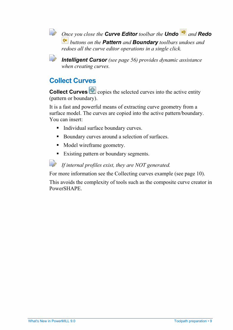
Once you close the Curve Editor toolbar the Undo and Redo buttons on the Pattern and Boundary toolbars undoes and
redoes all the curve editor operations in a single click.
Intelligent Cursor (see page 56) provides dynamic assistance when creating curves.
Collect Curves Collect Curves copies the selected curves into the active entity (pattern or boundary). It is a fast and powerful means of extracting curve geometry from a surface model. The curves are copied into the active pattern/boundary. You can insert:
Individual surface boundary curves. Boundary curves around a selection of surfaces. Model wireframe geometry. Existing pattern or boundary segments.
If internal profiles exist, they are NOT generated. For more information see the Collecting curves example (see page 10). This avoids the complexity of tools such as the composite curve creator in PowerSHAPE.
10 • Toolpath preparation What's New in PowerMILL 9.0
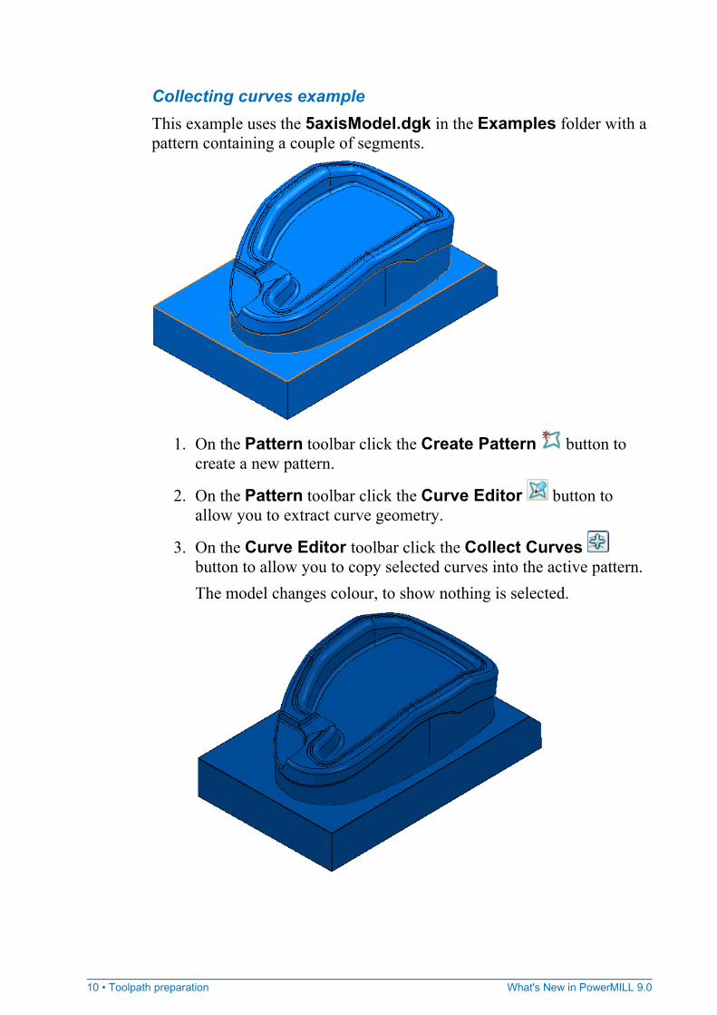
Collecting curves example This example uses the 5axisModel.dgk in the Examples folder with a pattern containing a couple of segments.
1. On the Pattern toolbar click the Create Pattern button to
create a new pattern.
2. On the Pattern toolbar click the Curve Editor button to allow you to extract curve geometry.
3. On the Curve Editor toolbar click the Collect Curves button to allow you to copy selected curves into the active pattern. The model changes colour, to show nothing is selected.
What's New in PowerMILL 9.0 Toolpath preparation • 11
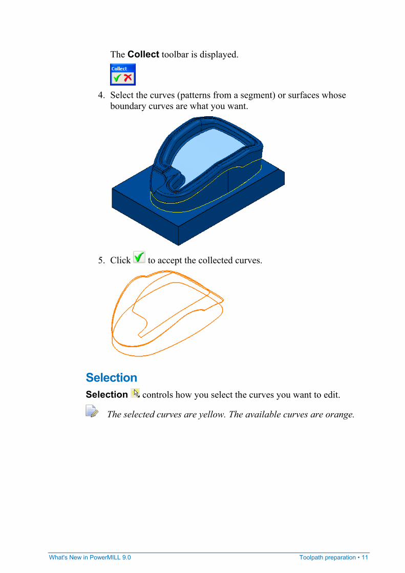
The Collect toolbar is displayed.
4. Select the curves (patterns from a segment) or surfaces whose
boundary curves are what you want.
5. Click to accept the collected curves.
Selection Selection controls how you select the curves you want to edit.
The selected curves are yellow. The available curves are orange.
12 • Toolpath preparation What's New in PowerMILL 9.0
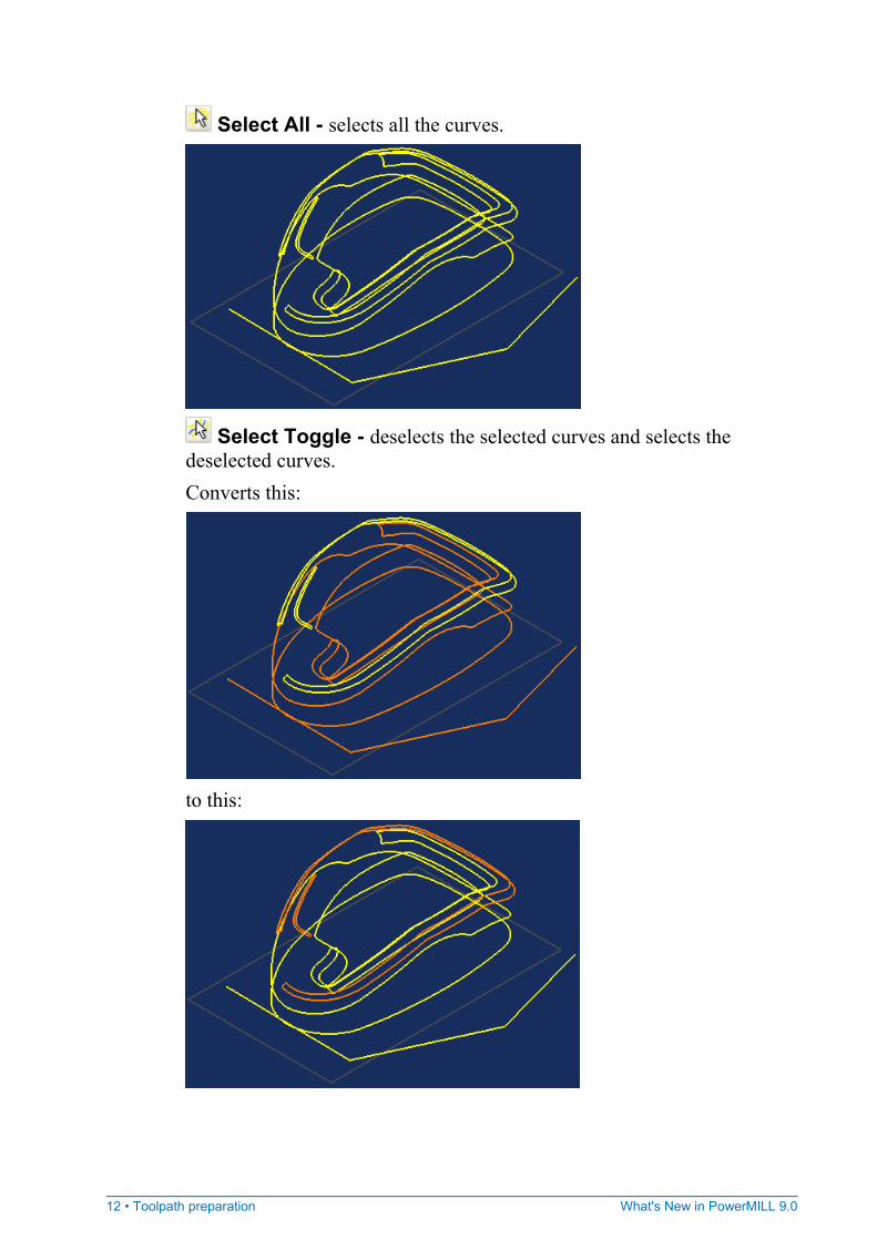
Select All - selects all the curves.
Select Toggle - deselects the selected curves and selects the deselected curves. Converts this:
to this:
What's New in PowerMILL 9.0 Toolpath preparation • 13
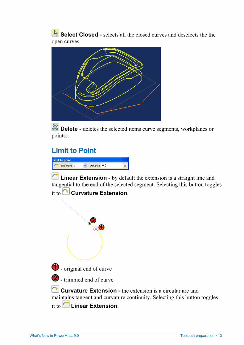
Select Closed - selects all the closed curves and deselects the the open curves.
Delete - deletes the selected items curve segments, workplanes or points).
Limit to Point
Linear Extension - by default the extension is a straight line and tangential to the end of the selected segment. Selecting this button toggles it to Curvature Extension.
- original end of curve
- trimmed end of curve
Curvature Extension - the extension is a circular arc and maintains tangent and curvature continuity. Selecting this button toggles it to Linear Extension.
14 • Toolpath preparation What's New in PowerMILL 9.0
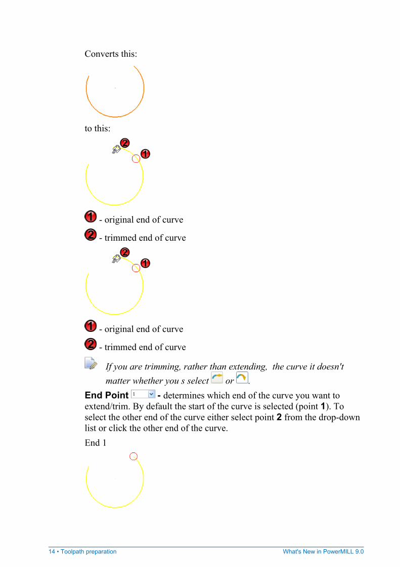
Converts this:
to this:
- original end of curve
- trimmed end of curve
- original end of curve
- trimmed end of curve
If you are trimming, rather than extending, the curve it doesn't matter whether you s select or .
End Point - determines which end of the curve you want to extend/trim. By default the start of the curve is selected (point 1). To select the other end of the curve either select point 2 from the drop-down list or click the other end of the curve. End 1
What's New in PowerMILL 9.0 Toolpath preparation • 15
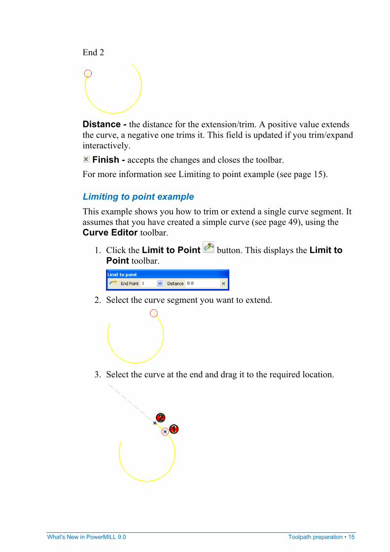
End 2
Distance - the distance for the extension/trim. A positive value extends the curve, a negative one trims it. This field is updated if you trim/expand interactively.
Finish - accepts the changes and closes the toolbar. For more information see Limiting to point example (see page 15).
Limiting to point example This example shows you how to trim or extend a single curve segment. It assumes that you have created a simple curve (see page 49), using the Curve Editor toolbar.
1. Click the Limit to Point button. This displays the Limit to Point toolbar.
2. Select the curve segment you want to extend.
3. Select the curve at the end and drag it to the required location.
16 • Toolpath preparation What's New in PowerMILL 9.0
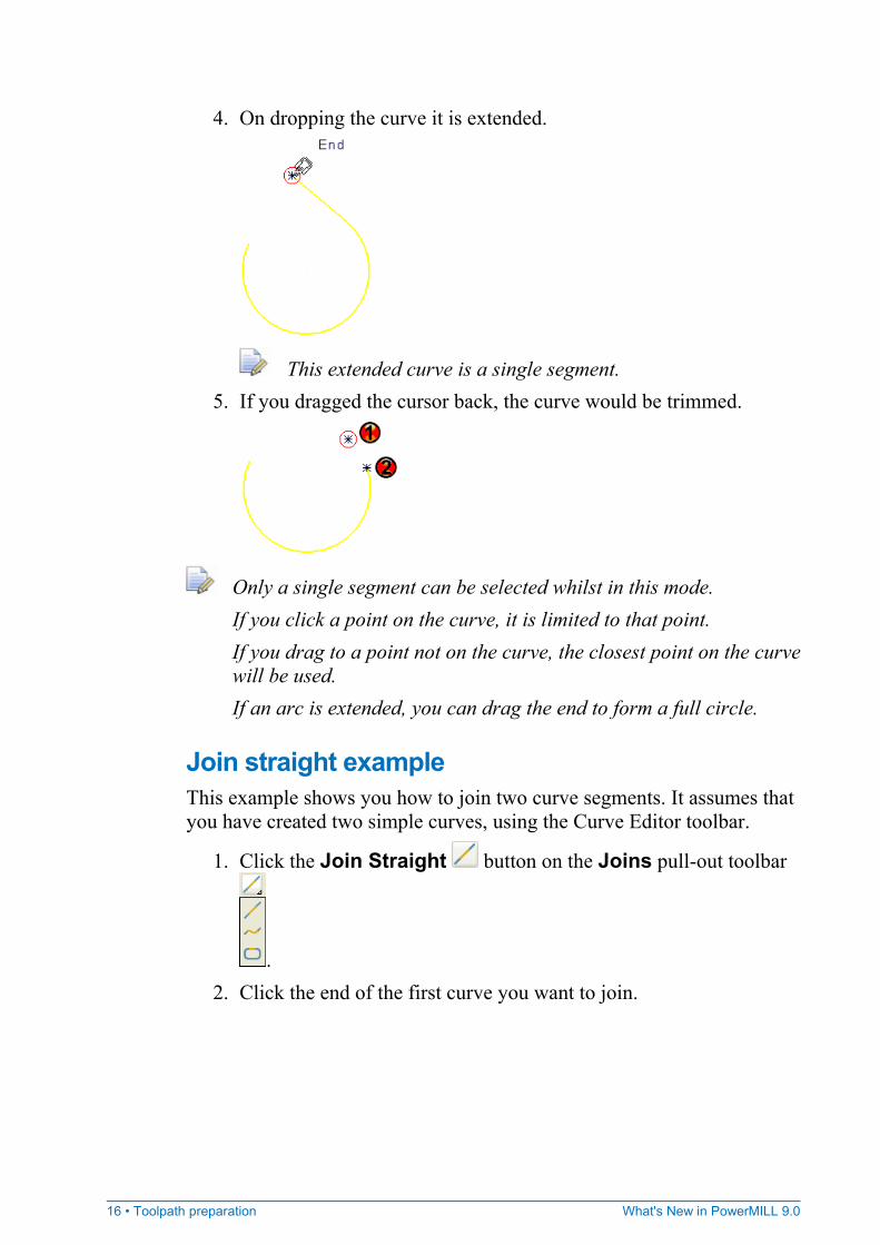
4. On dropping the curve it is extended.
This extended curve is a single segment. 5. If you dragged the cursor back, the curve would be trimmed.
Only a single segment can be selected whilst in this mode. If you click a point on the curve, it is limited to that point. If you drag to a point not on the curve, the closest point on the curve will be used. If an arc is extended, you can drag the end to form a full circle.
Join straight example This example shows you how to join two curve segments. It assumes that you have created two simple curves, using the Curve Editor toolbar.
1. Click the Join Straight button on the Joins pull-out toolbar
. 2. Click the end of the first curve you want to join.
What's New in PowerMILL 9.0 Toolpath preparation • 17
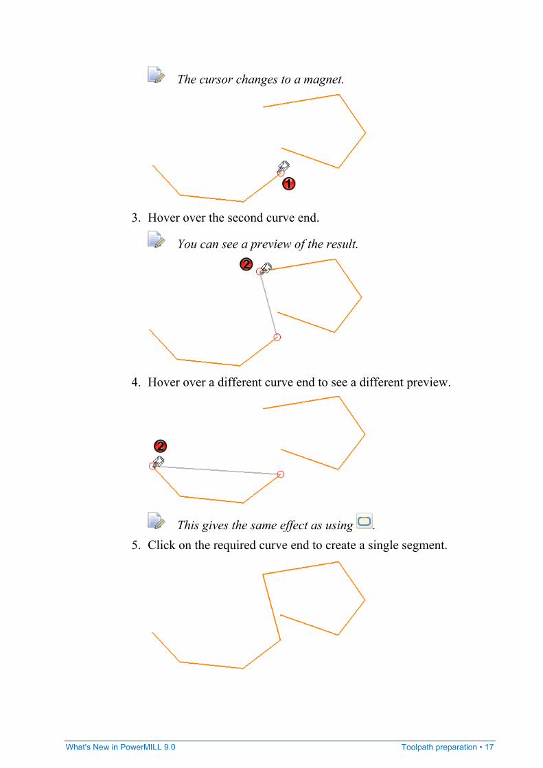
The cursor changes to a magnet.
3. Hover over the second curve end.
You can see a preview of the result.
4. Hover over a different curve end to see a different preview.
This gives the same effect as using . 5. Click on the required curve end to create a single segment.
18 • Toolpath preparation What's New in PowerMILL 9.0
The two initial curves and the joining segment are merged into one.
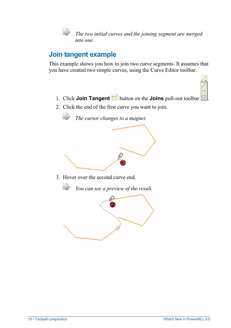
Join tangent example This example shows you how to join two curve segments. It assumes that you have created two simple curves, using the Curve Editor toolbar.
1. Click Join Tangent button on the Joins pull-out toolbar . 2. Click the end of the first curve you want to join.
The cursor changes to a magnet.
3. Hover over the second curve end.
You can see a preview of the result.
What's New in PowerMILL 9.0 Toolpath preparation • 19
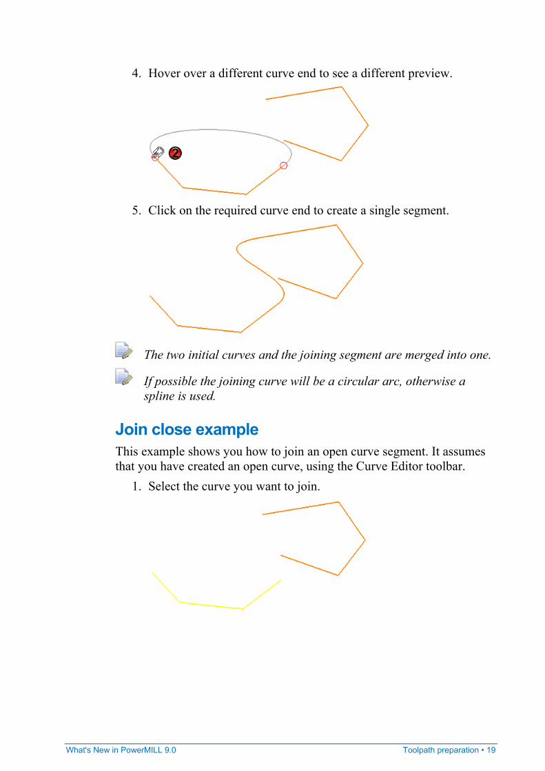
4. Hover over a different curve end to see a different preview.
5. Click on the required curve end to create a single segment.
The two initial curves and the joining segment are merged into one.
If possible the joining curve will be a circular arc, otherwise a spline is used.
Join close example This example shows you how to join an open curve segment. It assumes that you have created an open curve, using the Curve Editor toolbar.
1. Select the curve you want to join.
20 • Toolpath preparation What's New in PowerMILL 9.0
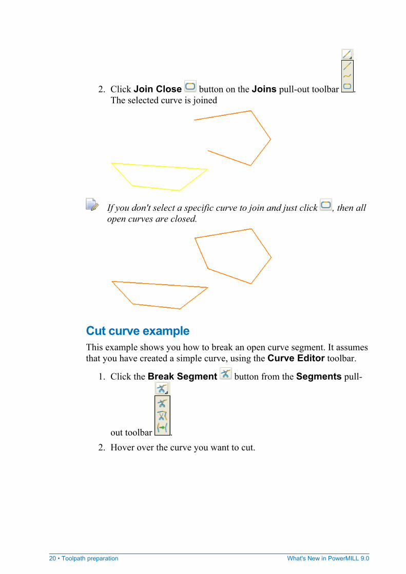
2. Click Join Close button on the Joins pull-out toolbar . The selected curve is joined
If you don't select a specific curve to join and just click , then all open curves are closed.
Cut curve example This example shows you how to break an open curve segment. It assumes that you have created a simple curve, using the Curve Editor toolbar.
1. Click the Break Segment button from the Segments pull-
out toolbar . 2. Hover over the curve you want to cut.
What's New in PowerMILL 9.0 Toolpath preparation • 21
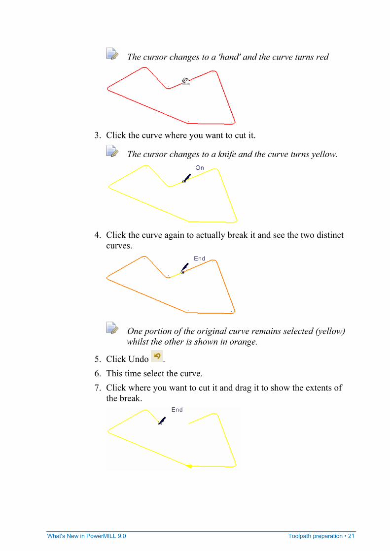
The cursor changes to a 'hand' and the curve turns red
3. Click the curve where you want to cut it.
The cursor changes to a knife and the curve turns yellow.
4. Click the curve again to actually break it and see the two distinct
curves.
One portion of the original curve remains selected (yellow) whilst the other is shown in orange.
5. Click Undo . 6. This time select the curve. 7. Click where you want to cut it and drag it to show the extents of
the break.
22 • Toolpath preparation What's New in PowerMILL 9.0
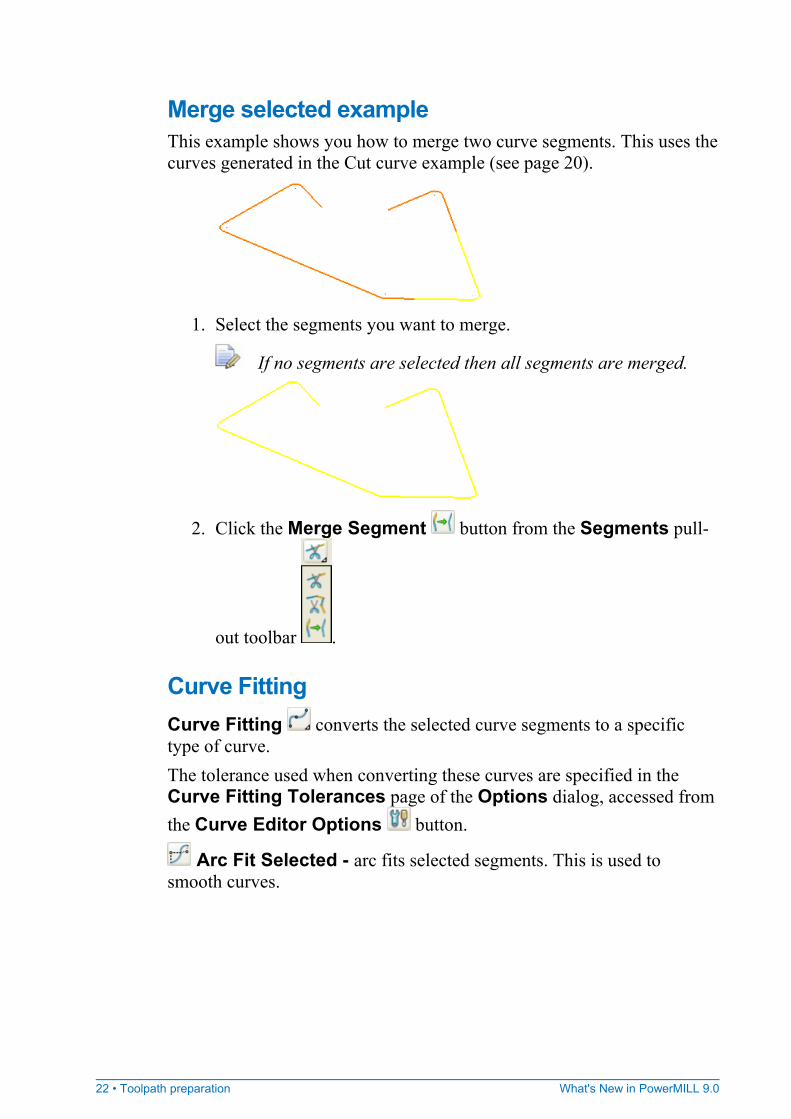
Merge selected example This example shows you how to merge two curve segments. This uses the curves generated in the Cut curve example (see page 20).
1. Select the segments you want to merge.
If no segments are selected then all segments are merged.
2. Click the Merge Segment button from the Segments pull-
out toolbar .
Curve Fitting Curve Fitting converts the selected curve segments to a specific type of curve. The tolerance used when converting these curves are specified in the Curve Fitting Tolerances page of the Options dialog, accessed from the Curve Editor Options button.
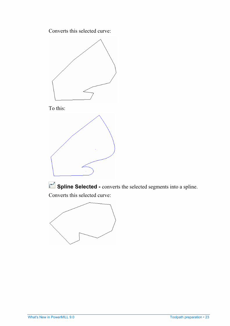
Arc Fit Selected - arc fits selected segments. This is used to smooth curves.
What's New in PowerMILL 9.0 Toolpath preparation • 23
Converts this selected curve:
To this:
Spline Selected - converts the selected segments into a spline. Converts this selected curve:

24 • Toolpath preparation What's New in PowerMILL 9.0
To this:
Polygonise Selected - converts the selected segments to a series
of straight lines. The curve is modified to the following:
Transformations Transformations allows you to move, rotate, scale or mirror curves. All of the options from the pull-out toolbar display their own individual toolbar.
Move - transforms the curves by the specified coordinates.
Rotate - rotates the curves around the specified axis by the selected angle.
What's New in PowerMILL 9.0 Toolpath preparation • 25
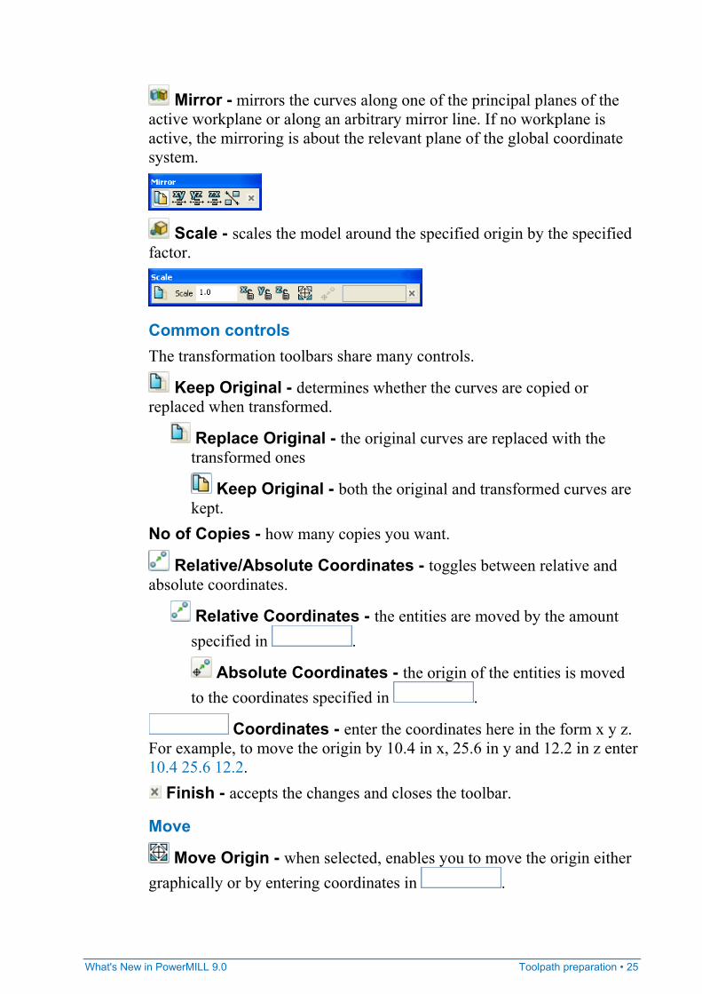
Mirror - mirrors the curves along one of the principal planes of the active workplane or along an arbitrary mirror line. If no workplane is active, the mirroring is about the relevant plane of the global coordinate system.
Scale - scales the model around the specified origin by the specified factor.
Common controls The transformation toolbars share many controls.
Keep Original - determines whether the curves are copied or replaced when transformed.
Replace Original - the original curves are replaced with the transformed ones
Keep Original - both the original and transformed curves are kept.
No of Copies - how many copies you want.
Relative/Absolute Coordinates - toggles between relative and absolute coordinates.
Relative Coordinates - the entities are moved by the amount specified in .
Absolute Coordinates - the origin of the entities is moved to the coordinates specified in .
Coordinates - enter the coordinates here in the form x y z. For example, to move the origin by 10.4 in x, 25.6 in y and 12.2 in z enter 10.4 25.6 12.2.
Finish - accepts the changes and closes the toolbar.
Move
Move Origin - when selected, enables you to move the origin either graphically or by entering coordinates in .
26 • Toolpath preparation What's New in PowerMILL 9.0
For more information see Move example (see page 27).
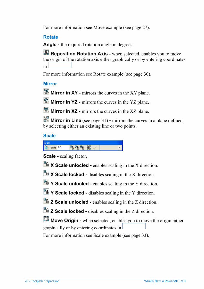
Rotate Angle - the required rotation angle in degrees.
Reposition Rotation Axis - when selected, enables you to move the origin of the rotation axis either graphically or by entering coordinates in . For more information see Rotate example (see page 30).
Mirror
Mirror in XY - mirrors the curves in the XY plane.
Mirror in YZ - mirrors the curves in the YZ plane.
Mirror in XZ - mirrors the curves in the XZ plane.
Mirror in Line (see page 31) - mirrors the curves in a plane defined by selecting either an existing line or two points.
Scale
Scale - scaling factor.
X Scale unlocled - enables scaling in the X direction.
X Scale locked - disables scaling in the X direction.
Y Scale unlocled - enables scaling in the Y direction.
Y Scale locked - disables scaling in the Y direction.
Z Scale unlocled - enables scaling in the Z direction.
Z Scale locked - disables scaling in the Z direction.
Move Origin - when selected, enables you to move the origin either graphically or by entering coordinates in . For more information see Scale example (see page 33).
What's New in PowerMILL 9.0 Toolpath preparation • 27
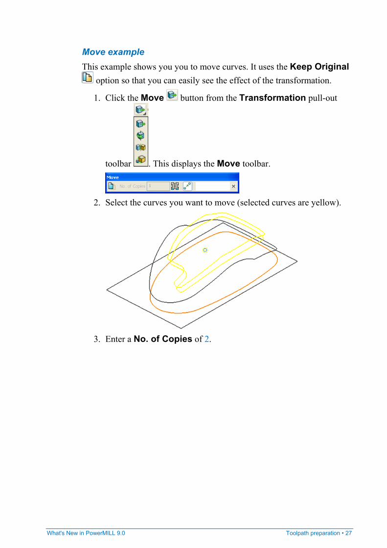
Move example This example shows you you to move curves. It uses the Keep Original
option so that you can easily see the effect of the transformation.
1. Click the Move button from the Transformation pull-out
toolbar . This displays the Move toolbar.
2. Select the curves you want to move (selected curves are yellow).
3. Enter a No. of Copies of 2.
28 • Toolpath preparation What's New in PowerMILL 9.0
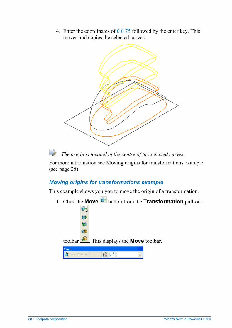
4. Enter the coordinates of 0 0 75 followed by the enter key. This moves and copies the selected curves.
The origin is located in the centre of the selected curves. For more information see Moving origins for transformations example (see page 28).
Moving origins for transformations example This example shows you you to move the origin of a transformation.
1. Click the Move button from the Transformation pull-out
toolbar . This displays the Move toolbar.
What's New in PowerMILL 9.0 Toolpath preparation • 29
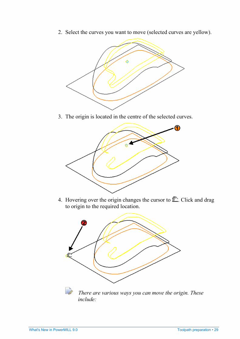
2. Select the curves you want to move (selected curves are yellow).
3. The origin is located in the centre of the selected curves.
4. Hovering over the origin changes the cursor to . Click and drag
to origin to the required location.
There are various ways you can move the origin. These include:
30 • Toolpath preparation What's New in PowerMILL 9.0
Click and then click (not drag) the new position.
Click and enter the absolute or relative coordinates.
Rotate example This example shows you you to rotate curves. It uses the Keep Original
option so that you can easily see the effect of the transformation.
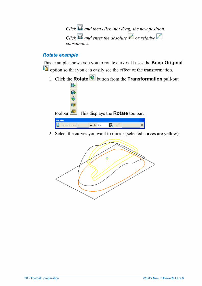
1. Click the Rotate button from the Transformation pull-out
toolbar . This displays the Rotate toolbar.
2. Select the curves you want to mirror (selected curves are yellow).
What's New in PowerMILL 9.0 Toolpath preparation • 31
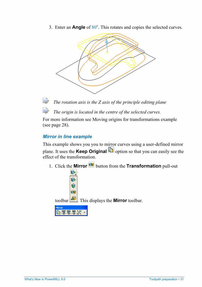
3. Enter an Angle of 80 . This rotates and copies the selected curves.
The rotation axis is the Z axis of the principle editing plane
The origin is located in the centre of the selected curves. For more information see Moving origins for transformations example (see page 28).
Mirror in line example This example shows you you to mirror curves using a user-defined mirror plane. It uses the Keep Original option so that you can easily see the effect of the transformation.
1. Click the Mirror button from the Transformation pull-out
toolbar . This displays the Mirror toolbar.
32 • Toolpath preparation What's New in PowerMILL 9.0
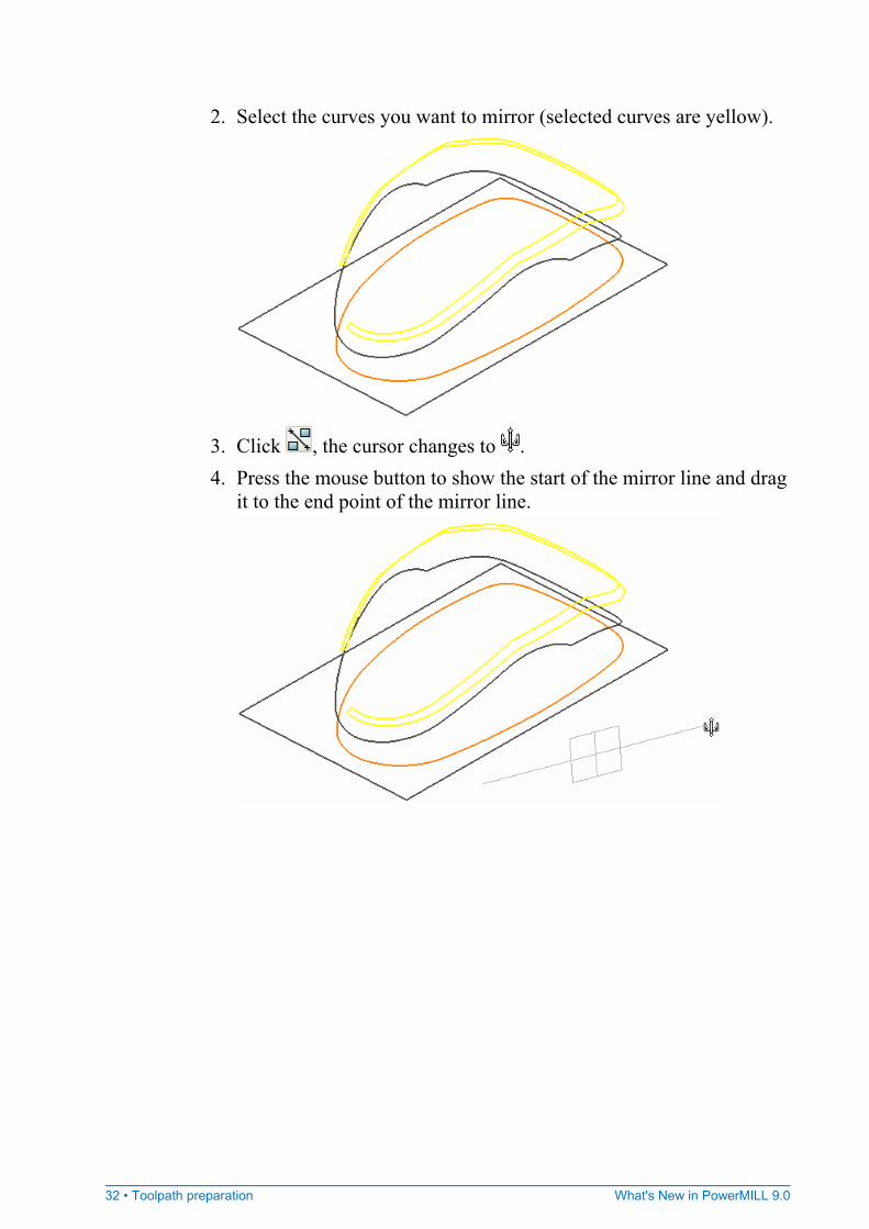
2. Select the curves you want to mirror (selected curves are yellow).
3. Click , the cursor changes to . 4. Press the mouse button to show the start of the mirror line and drag
it to the end point of the mirror line.
What's New in PowerMILL 9.0 Toolpath preparation • 33
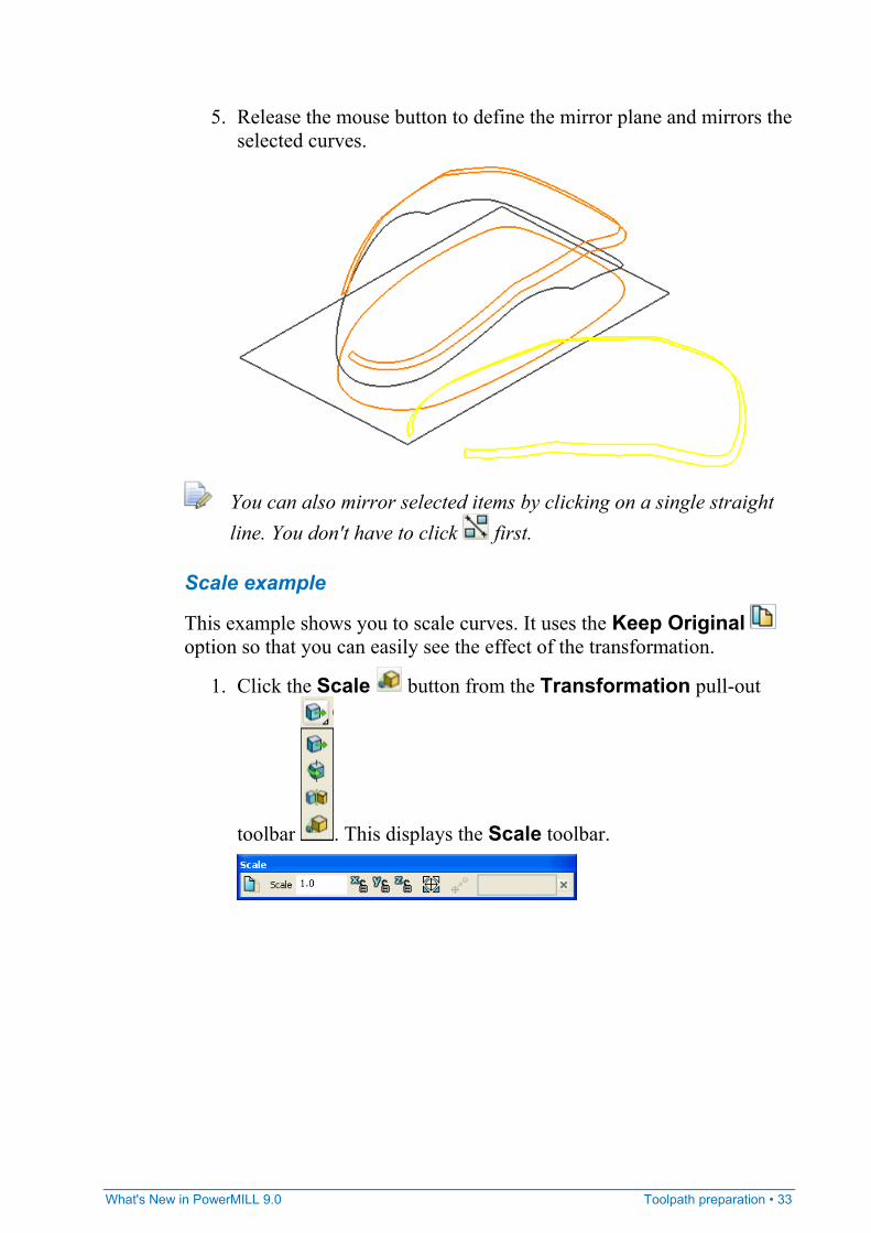
5. Release the mouse button to define the mirror plane and mirrors the selected curves.
You can also mirror selected items by clicking on a single straight line. You don't have to click first.
Scale example
This example shows you to scale curves. It uses the Keep Original option so that you can easily see the effect of the transformation.
1. Click the Scale button from the Transformation pull-out
toolbar . This displays the Scale toolbar.
34 • Toolpath preparation What's New in PowerMILL 9.0
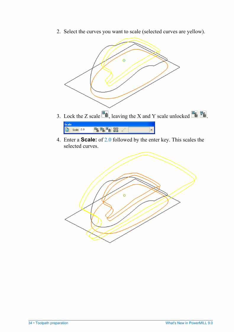
2. Select the curves you want to scale (selected curves are yellow).
3. Lock the Z scale , leaving the X and Y scale unlocked .
4. Enter a Scale: of 2.0 followed by the enter key. This scales the
selected curves.
What's New in PowerMILL 9.0 Toolpath preparation • 35
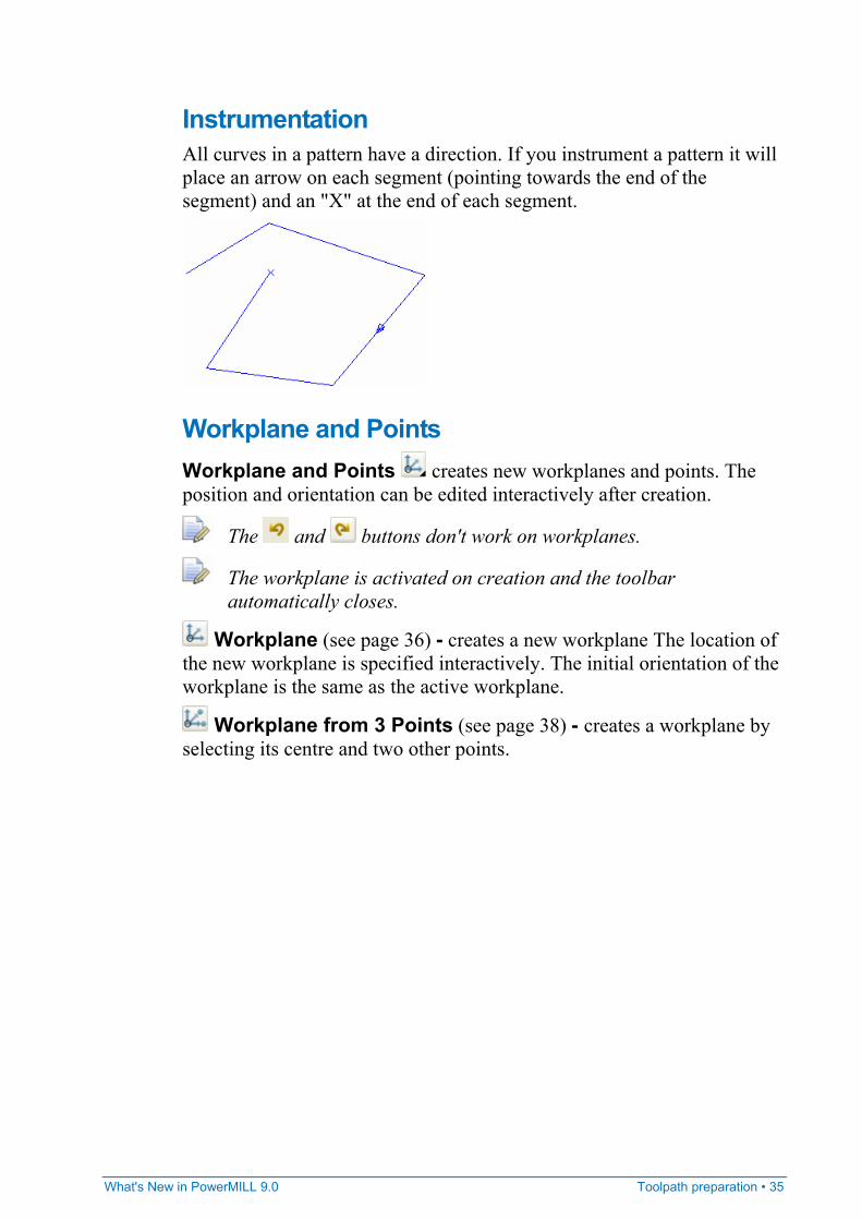
Instrumentation All curves in a pattern have a direction. If you instrument a pattern it will place an arrow on each segment (pointing towards the end of the segment) and an "X" at the end of each segment.
Workplane and Points Workplane and Points creates new workplanes and points. The position and orientation can be edited interactively after creation.
The and buttons don't work on workplanes.
The workplane is activated on creation and the toolbar automatically closes.
Workplane (see page 36) - creates a new workplane The location of the new workplane is specified interactively. The initial orientation of the workplane is the same as the active workplane.
Workplane from 3 Points (see page 38) - creates a workplane by selecting its centre and two other points.
36 • Toolpath preparation What's New in PowerMILL 9.0
Workplane Align to Geometry - aligns the workplane so that it is located where you select, and is normal to the curve or surface at that point. The workplane location is controlled interactively, the Z axis is normal to the selected curve.
Create Points - creates new points. The location of the points are defined either interactively or by entering the required coordinates.
Create workplane example This example shows you how to create and manipulate workplanes graphically from within the Curve Editor toolbar.
1. Initially you must define the origin of the workplane. Click the Create a Workplane button from the Workplane pull-out
toolbar . This displays the Create a Workplane toolbar. If you move your cursor in the graphics window you will also see the cursor with a workplane attached.

What's New in PowerMILL 9.0 Toolpath preparation • 37
2. Either click in the graphics area to create a new workplane or click on some geometry to locate the workplane at a specific location.
In either case once you have selected the workplane location it turns red since it is now the active workplane.
3. Now define the orientation of the workplane by interactive editing.
Click on the red workplane. It turns yellow and blue. 4. Click and drag on a yellow or blue area changes the orientation of
the workplane.
The blue areas allow rotations about the Z axis. The yellow areas allow rotations about the X or Y axis. The black area allows translation of the workplane origin.
- aligns the Z axis with a user specified point. Similarly selecting the yellow arrow heads of the X or Y axis allows alignment of these axes.
- moves the origin.
- rotates around the Z axis
38 • Toolpath preparation What's New in PowerMILL 9.0
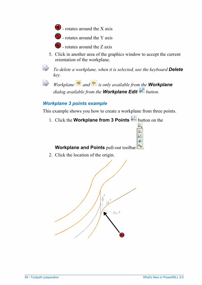
- rotates around the X axis
- rotates around the Y axis
- rotates around the Z axis 5. Click in another area of the graphics window to accept the current
orientation of the workplane.
To delete a workplane, when it is selected, use the keyboard Delete key.
Workplane and is only available from the Workplane dialog available from the Workplane Edit button.
Workplane 3 points example This example shows you how to create a workplane from three points.
1. Click the Workplane from 3 Points button on the
Workplane and Points pull-out toolbar . 2. Click the location of the origin.
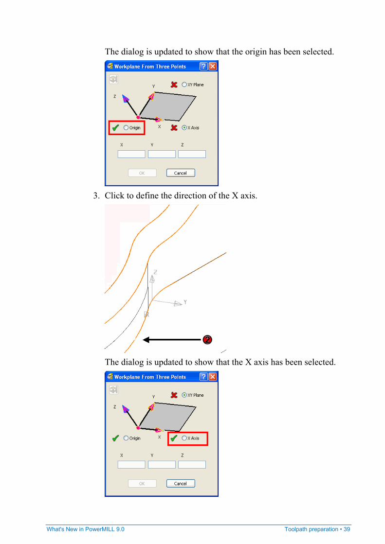
What's New in PowerMILL 9.0 Toolpath preparation • 39
The dialog is updated to show that the origin has been selected.
3. Click to define the direction of the X axis.
The dialog is updated to show that the X axis has been selected.
40 • Toolpath preparation What's New in PowerMILL 9.0
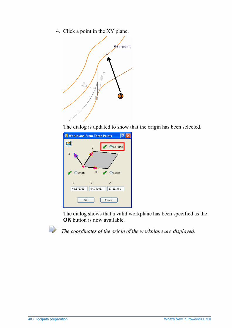
4. Click a point in the XY plane.
The dialog is updated to show that the origin has been selected.
The dialog shows that a valid workplane has been specified as the OK button is now available.
The coordinates of the origin of the workplane are displayed.
What's New in PowerMILL 9.0 Toolpath preparation • 41
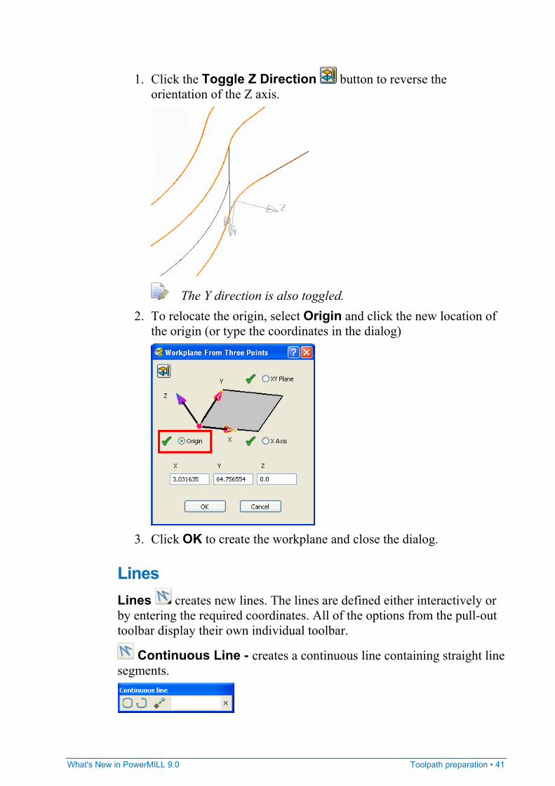
1. Click the Toggle Z Direction button to reverse the orientation of the Z axis.
The Y direction is also toggled. 2. To relocate the origin, select Origin and click the new location of
the origin (or type the coordinates in the dialog)
3. Click OK to create the workplane and close the dialog.
Lines Lines creates new lines. The lines are defined either interactively or by entering the required coordinates. All of the options from the pull-out toolbar display their own individual toolbar.
Continuous Line - creates a continuous line containing straight line segments.
42 • Toolpath preparation What's New in PowerMILL 9.0
Single Line - creates a single line.
Rectangle - creates a rectangular continuous line containing four straight line segments.
Common controls The lines toolbars share some controls.
Relative/Absolute Coordinates - toggles between relative and absolute coordinates.
Relative Coordinates - the coordinates are relative to the currently selected location and specified in .
Absolute Coordinates - the coordinates are relative to workplane origin location and specified in .
Finish - accepts the changes and closes the toolbar.
Continuous Line
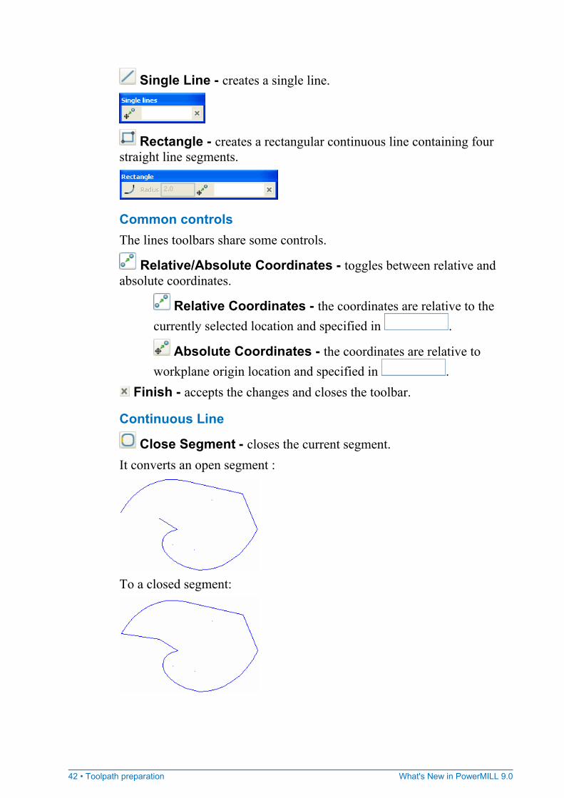
Close Segment - closes the current segment. It converts an open segment :
To a closed segment:
What's New in PowerMILL 9.0 Toolpath preparation • 43
Start New Segment - ends the current segment so the next point is the start of a new segment. For more information see the Create lines example (see page 43).
Rectangle
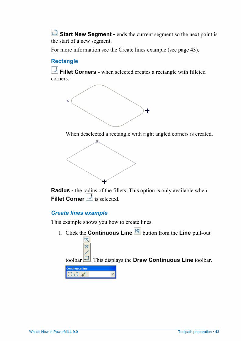
Fillet Corners - when selected creates a rectangle with filleted corners.
When deselected a rectangle with right angled corners is created.
Radius - the radius of the fillets. This option is only available when Fillet Corner is selected.
Create lines example This example shows you how to create lines.
1. Click the Continuous Line button from the Line pull-out
toolbar . This displays the Draw Continuous Line toolbar.
44 • Toolpath preparation What's New in PowerMILL 9.0
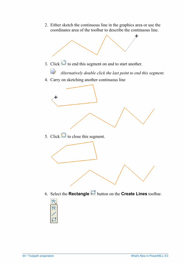
2. Either sketch the continuous line in the graphics area or use the coordinates area of the toolbar to describe the continuous line.
3. Click to end this segment on and to start another.
Alternatively double click the last point to end this segment. 4. Carry on sketching another continuous line
5. Click to close this segment.
6. Select the Rectangle button on the Create Lines toolbar.
What's New in PowerMILL 9.0 Toolpath preparation • 45
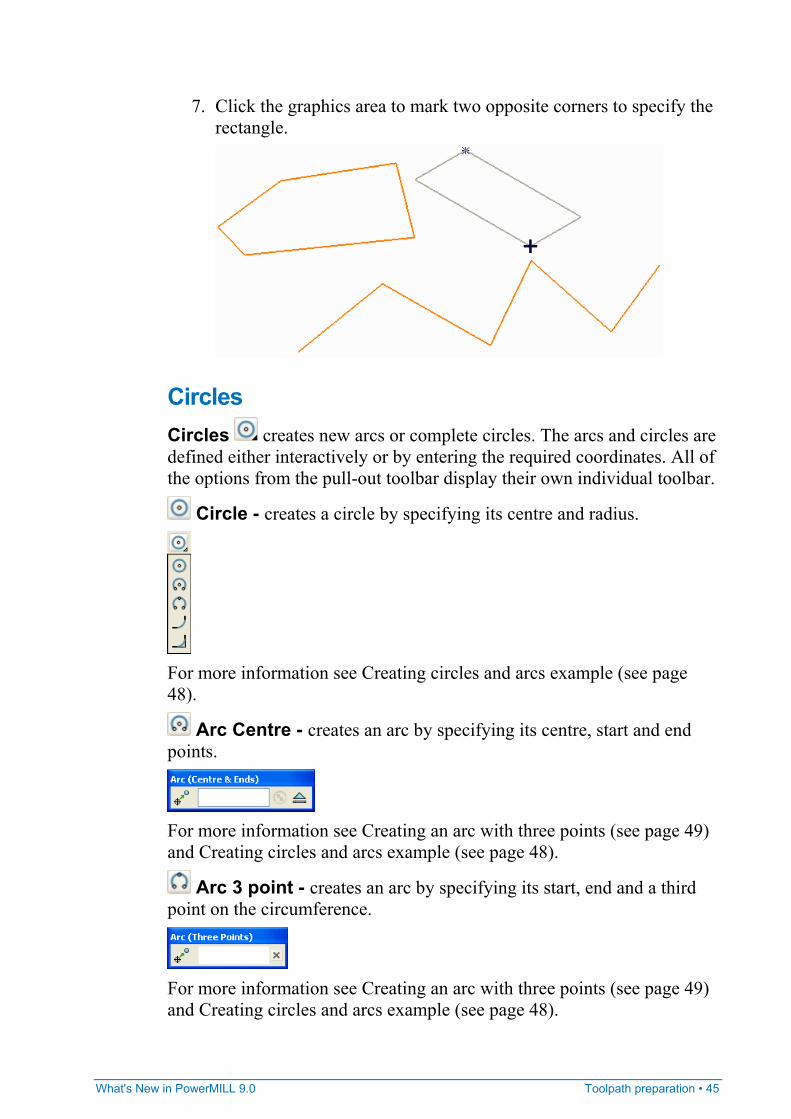
7. Click the graphics area to mark two opposite corners to specify the rectangle.
Circles Circles creates new arcs or complete circles. The arcs and circles are defined either interactively or by entering the required coordinates. All of the options from the pull-out toolbar display their own individual toolbar.
Circle - creates a circle by specifying its centre and radius.
For more information see Creating circles and arcs example (see page 48).
Arc Centre - creates an arc by specifying its centre, start and end points.
For more information see Creating an arc with three points (see page 49) and Creating circles and arcs example (see page 48).
Arc 3 point - creates an arc by specifying its start, end and a third point on the circumference.
For more information see Creating an arc with three points (see page 49) and Creating circles and arcs example (see page 48).
46 • Toolpath preparation What's New in PowerMILL 9.0
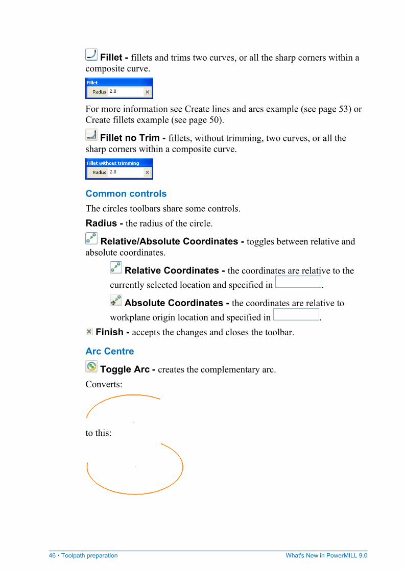
Fillet - fillets and trims two curves, or all the sharp corners within a composite curve.
For more information see Create lines and arcs example (see page 53) or Create fillets example (see page 50).
Fillet no Trim - fillets, without trimming, two curves, or all the sharp corners within a composite curve.
Common controls The circles toolbars share some controls. Radius - the radius of the circle.
Relative/Absolute Coordinates - toggles between relative and absolute coordinates.
Relative Coordinates - the coordinates are relative to the currently selected location and specified in .
Absolute Coordinates - the coordinates are relative to workplane origin location and specified in .
Finish - accepts the changes and closes the toolbar.
Arc Centre
Toggle Arc - creates the complementary arc. Converts:
to this:
What's New in PowerMILL 9.0 Toolpath preparation • 47
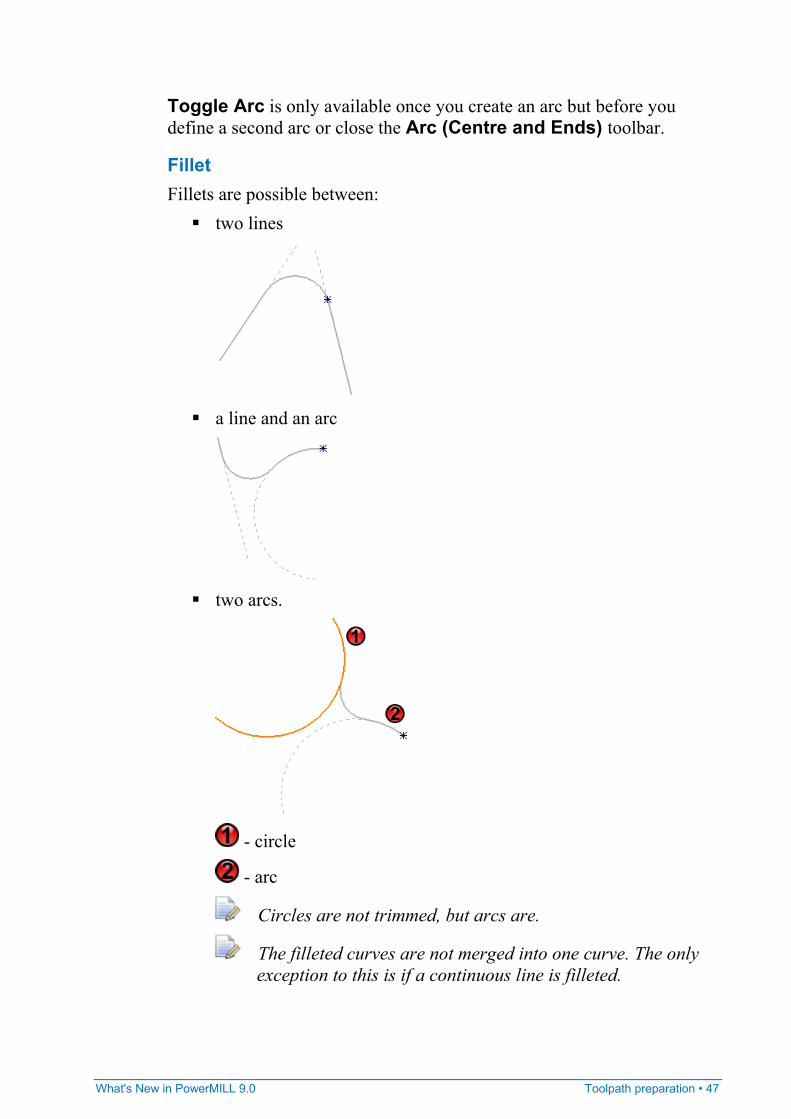
Toggle Arc is only available once you create an arc but before you define a second arc or close the Arc (Centre and Ends) toolbar.
Fillet Fillets are possible between:
two lines
a line and an arc
two arcs.
- circle
- arc
Circles are not trimmed, but arcs are.
The filleted curves are not merged into one curve. The only exception to this is if a continuous line is filleted.

48 • Toolpath preparation What's New in PowerMILL 9.0
Fillet no Trim
Fillets are always trimmed when you select a continuous line.
Apart from the trimming aspect this works in exactly the same way as Fillet.
Create circles and arcs example This example shows you how to create a circle and an arc.
1. Click the Circles button from the Circles pull-out toolbar
. This displays the Circle toolbar and the cursor changes to a circle.
2. Enter a suitable Radius of say 10. 3. Select the centre point of the arc in the graphics area.
What's New in PowerMILL 9.0 Toolpath preparation • 49
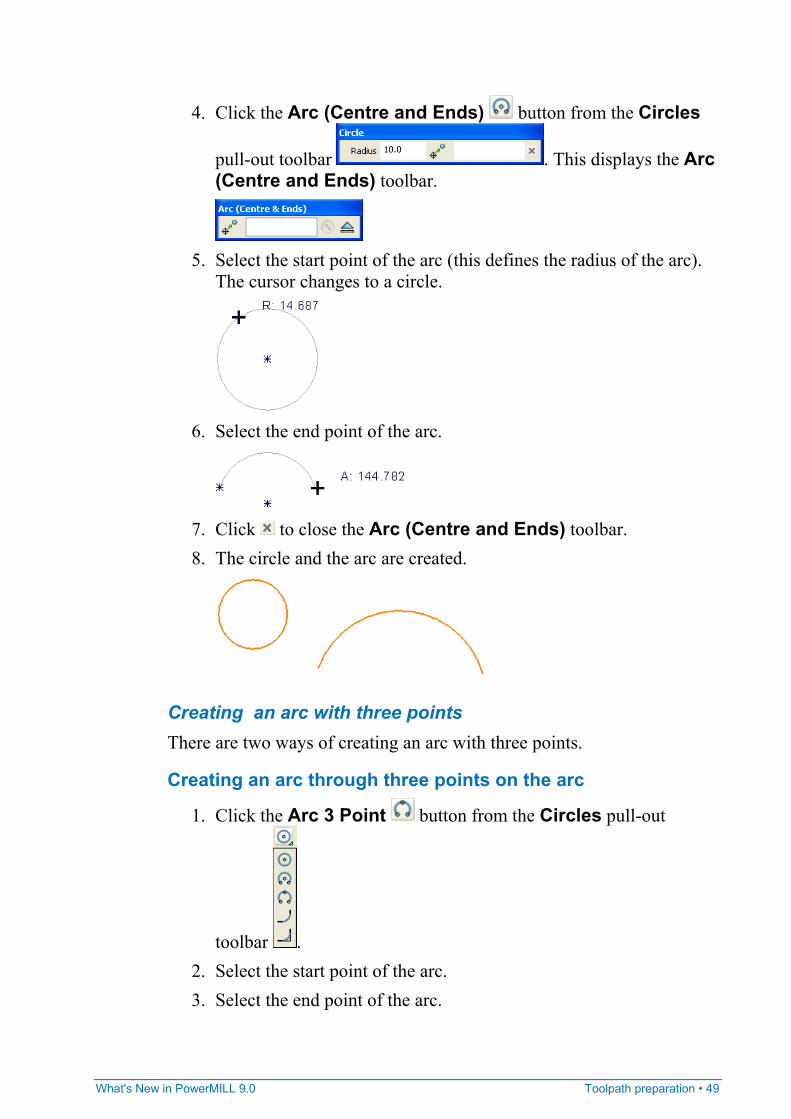
4. Click the Arc (Centre and Ends) button from the Circles
pull-out toolbar . This displays the Arc (Centre and Ends) toolbar.
5. Select the start point of the arc (this defines the radius of the arc).
The cursor changes to a circle.
6. Select the end point of the arc.
7. Click to close the Arc (Centre and Ends) toolbar. 8. The circle and the arc are created.
Creating an arc with three points There are two ways of creating an arc with three points.
Creating an arc through three points on the arc
1. Click the Arc 3 Point button from the Circles pull-out
toolbar . 2. Select the start point of the arc. 3. Select the end point of the arc.
50 • Toolpath preparation What's New in PowerMILL 9.0
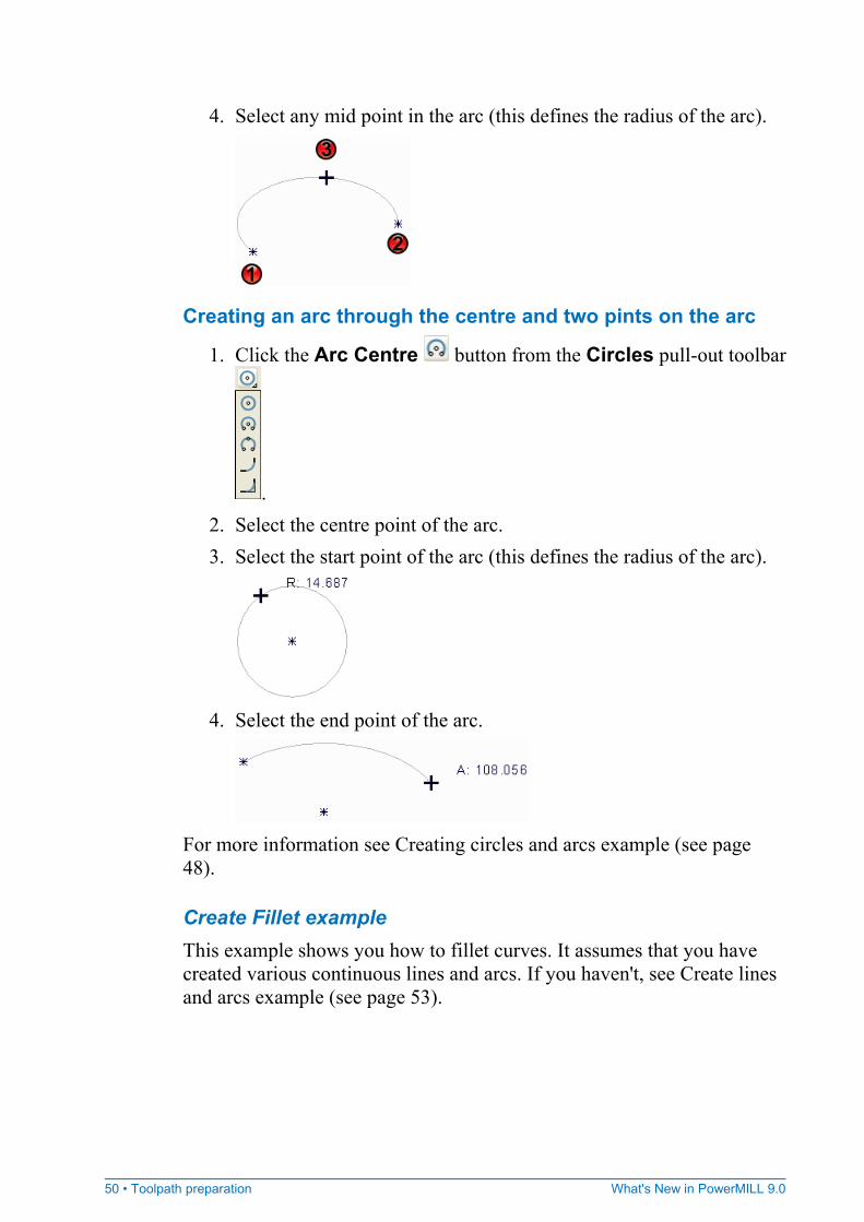
4. Select any mid point in the arc (this defines the radius of the arc).
Creating an arc through the centre and two pints on the arc
1. Click the Arc Centre button from the Circles pull-out toolbar
. 2. Select the centre point of the arc. 3. Select the start point of the arc (this defines the radius of the arc).
4. Select the end point of the arc.
For more information see Creating circles and arcs example (see page 48).
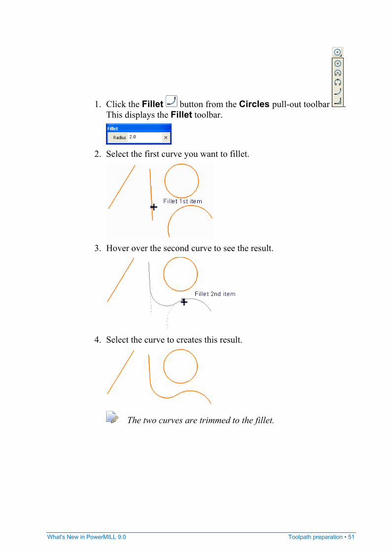
Create Fillet example This example shows you how to fillet curves. It assumes that you have created various continuous lines and arcs. If you haven't, see Create lines and arcs example (see page 53).
What's New in PowerMILL 9.0 Toolpath preparation • 51
1. Click the Fillet button from the Circles pull-out toolbar . This displays the Fillet toolbar.
2. Select the first curve you want to fillet.
3. Hover over the second curve to see the result.
4. Select the curve to creates this result.
The two curves are trimmed to the fillet.
52 • Toolpath preparation What's New in PowerMILL 9.0
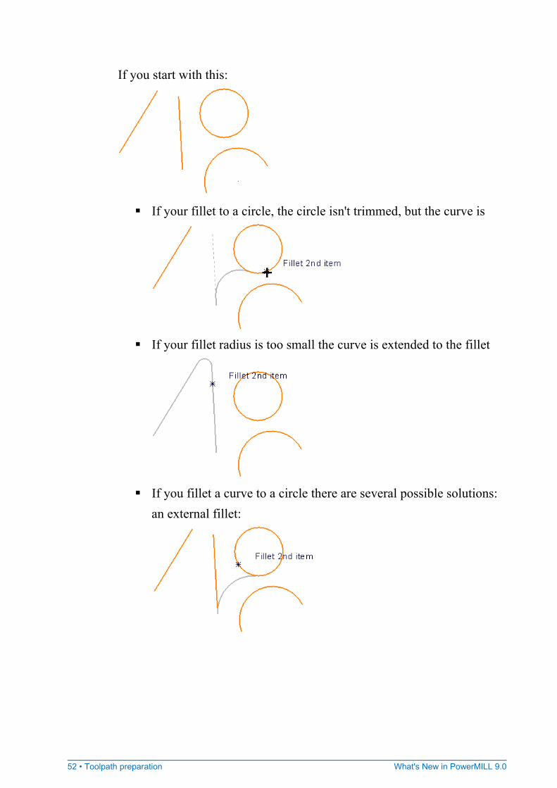
If you start with this:
If your fillet to a circle, the circle isn't trimmed, but the curve is
If your fillet radius is too small the curve is extended to the fillet
If you fillet a curve to a circle there are several possible solutions:
an external fillet:
What's New in PowerMILL 9.0 Toolpath preparation • 53
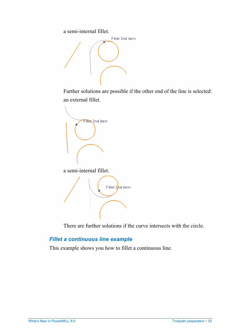
a semi-internal fillet.
Further solutions are possible if the other end of the line is selected: an external fillet.
a semi-internal fillet.
There are further solutions if the curve intersects with the circle.
Fillet a continuous line example This example shows you how to fillet a continuous line.
54 • Toolpath preparation What's New in PowerMILL 9.0
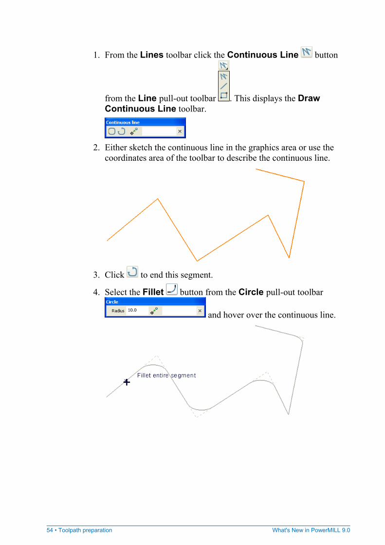
1. From the Lines toolbar click the Continuous Line button
from the Line pull-out toolbar . This displays the Draw Continuous Line toolbar.
2. Either sketch the continuous line in the graphics area or use the
coordinates area of the toolbar to describe the continuous line.
3. Click to end this segment.
4. Select the Fillet button from the Circle pull-out toolbar
and hover over the continuous line.
What's New in PowerMILL 9.0 Toolpath preparation • 55
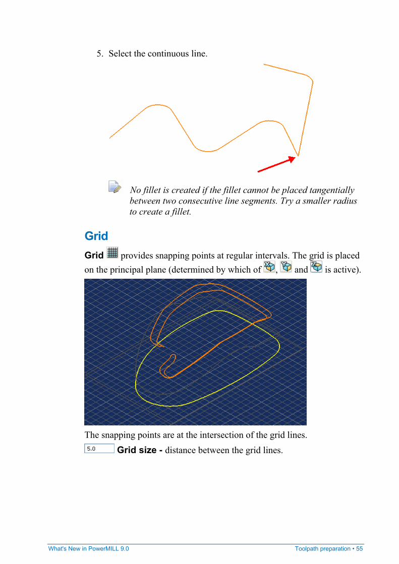
5. Select the continuous line.
No fillet is created if the fillet cannot be placed tangentially between two consecutive line segments. Try a smaller radius to create a fillet.
Grid Grid provides snapping points at regular intervals. The grid is placed on the principal plane (determined by which of , and is active).
The snapping points are at the intersection of the grid lines.
Grid size - distance between the grid lines.
56 • Toolpath preparation What's New in PowerMILL 9.0
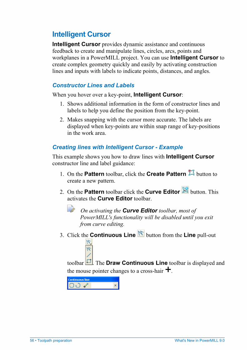
Intelligent Cursor Intelligent Cursor provides dynamic assistance and continuous feedback to create and manipulate lines, circles, arcs, points and workplanes in a PowerMILL project. You can use Intelligent Cursor to create complex geometry quickly and easily by activating construction lines and inputs with labels to indicate points, distances, and angles.
Constructor Lines and Labels When you hover over a key-point, Intelligent Cursor:
1. Shows additional information in the form of constructor lines and labels to help you define the position from the key-point.
2. Makes snapping with the cursor more accurate. The labels are displayed when key-points are within snap range of key-positions in the work area.
Creating lines with Intelligent Cursor - Example This example shows you how to draw lines with Intelligent Cursor constructor line and label guidance:
1. On the Pattern toolbar, click the Create Pattern button to create a new pattern.
2. On the Pattern toolbar click the Curve Editor button. This activates the Curve Editor toolbar.
On activating the Curve Editor toolbar, most of PowerMILL's functionality will be disabled until you exit from curve editing.
3. Click the Continuous Line button from the Line pull-out
toolbar . The Draw Continuous Line toolbar is displayed and the mouse pointer changes to a cross-hair .
What's New in PowerMILL 9.0 Toolpath preparation • 57
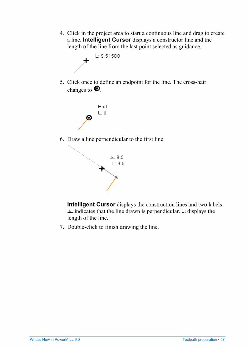
4. Click in the project area to start a continuous line and drag to create a line. Intelligent Cursor displays a constructor line and the length of the line from the last point selected as guidance.
5. Click once to define an endpoint for the line. The cross-hair
changes to .
6. Draw a line perpendicular to the first line.
Intelligent Cursor displays the construction lines and two labels.
indicates that the line drawn is perpendicular. displays the length of the line.
7. Double-click to finish drawing the line.
58 • Toolpath preparation What's New in PowerMILL 9.0
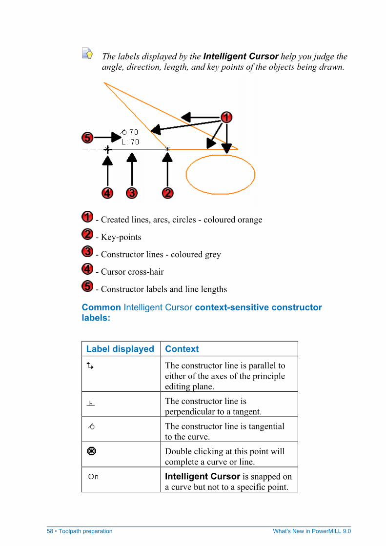
The labels displayed by the Intelligent Cursor help you judge the angle, direction, length, and key points of the objects being drawn.
- Created lines, arcs, circles - coloured orange
- Key-points
- Constructor lines - coloured grey
- Cursor cross-hair
- Constructor labels and line lengths
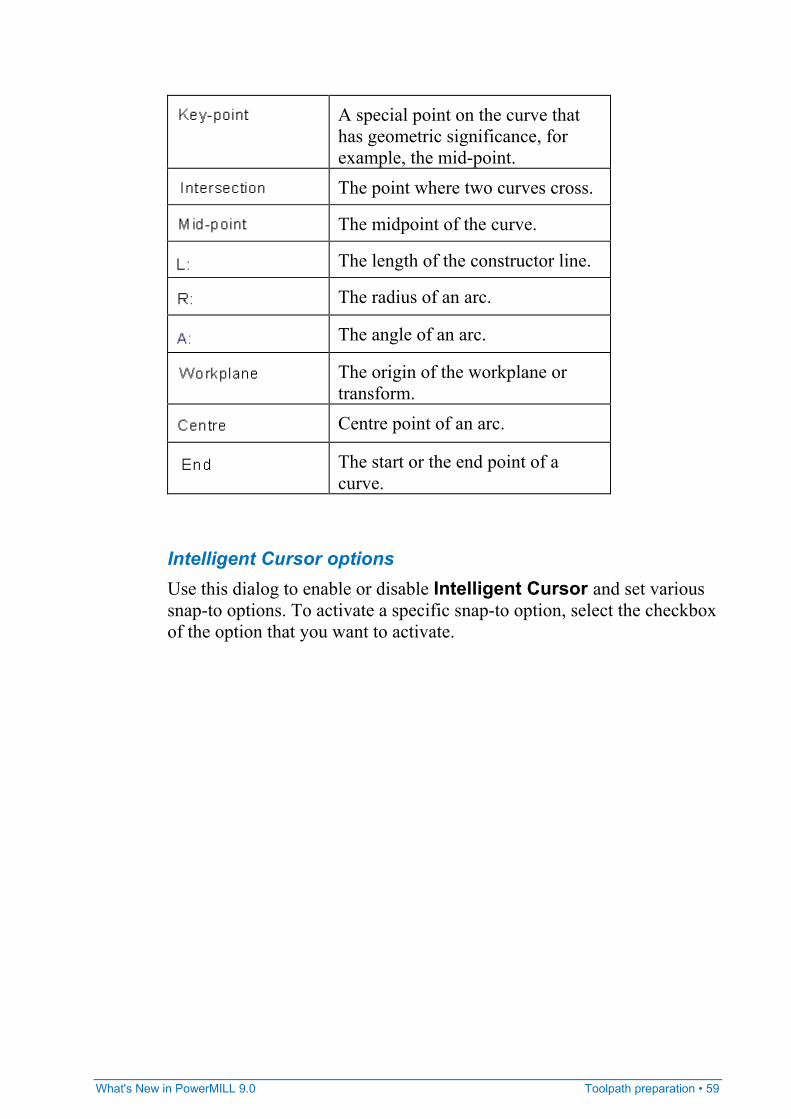
Common Intelligent Cursor context-sensitive constructor labels:
Label displayed Context
The constructor line is parallel to either of the axes of the principle editing plane.
The constructor line is perpendicular to a tangent.
The constructor line is tangential to the curve.
Double clicking at this point will complete a curve or line.
Intelligent Cursor is snapped on a curve but not to a specific point.
What's New in PowerMILL 9.0 Toolpath preparation • 59
A special point on the curve that has geometric significance, for example, the mid-point.
The point where two curves cross.
The midpoint of the curve.
The length of the constructor line.
The radius of an arc.
The angle of an arc.
The origin of the workplane or transform.
Centre point of an arc.
The start or the end point of a curve.
Intelligent Cursor options Use this dialog to enable or disable Intelligent Cursor and set various snap-to options. To activate a specific snap-to option, select the checkbox of the option that you want to activate.
60 • Toolpath preparation What's New in PowerMILL 9.0
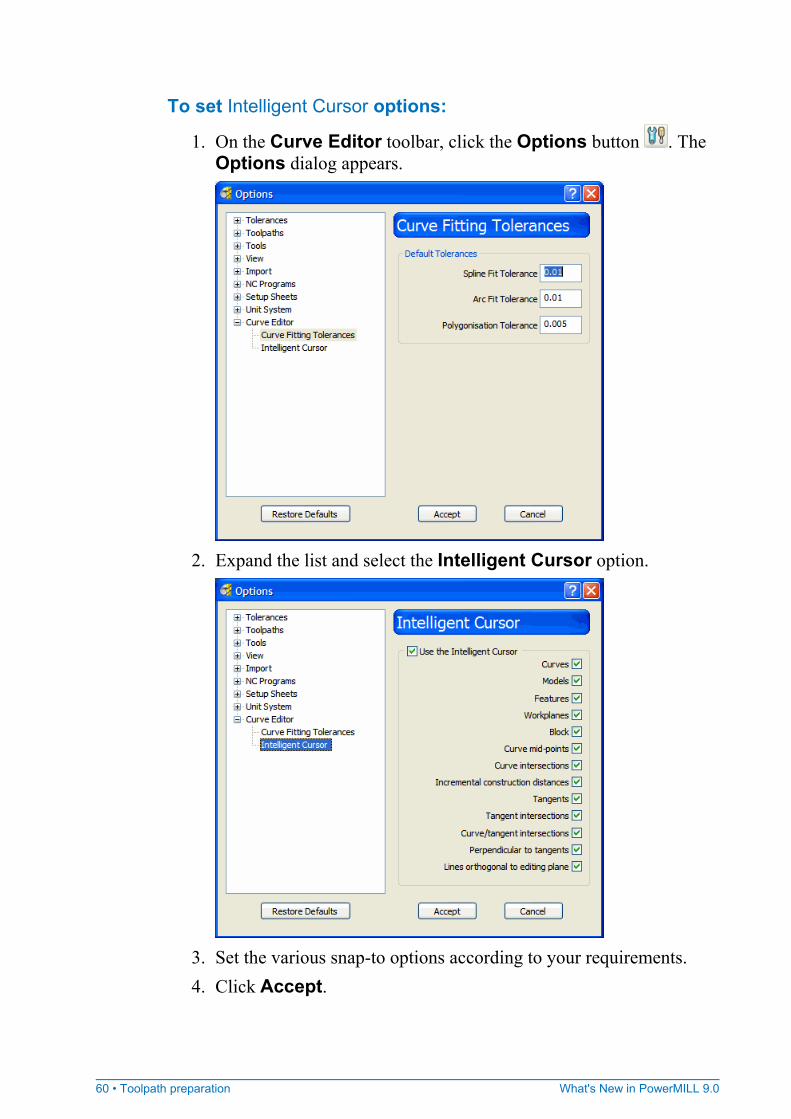
To set Intelligent Cursor options:
1. On the Curve Editor toolbar, click the Options button . The Options dialog appears.
2. Expand the list and select the Intelligent Cursor option.
3. Set the various snap-to options according to your requirements. 4. Click Accept.

What's New in PowerMILL 9.0 Toolpath preparation • 61
Intelligent Cursor and all snap-to options are enabled by default.
62 • Toolpath preparation What's New in PowerMILL 9.0
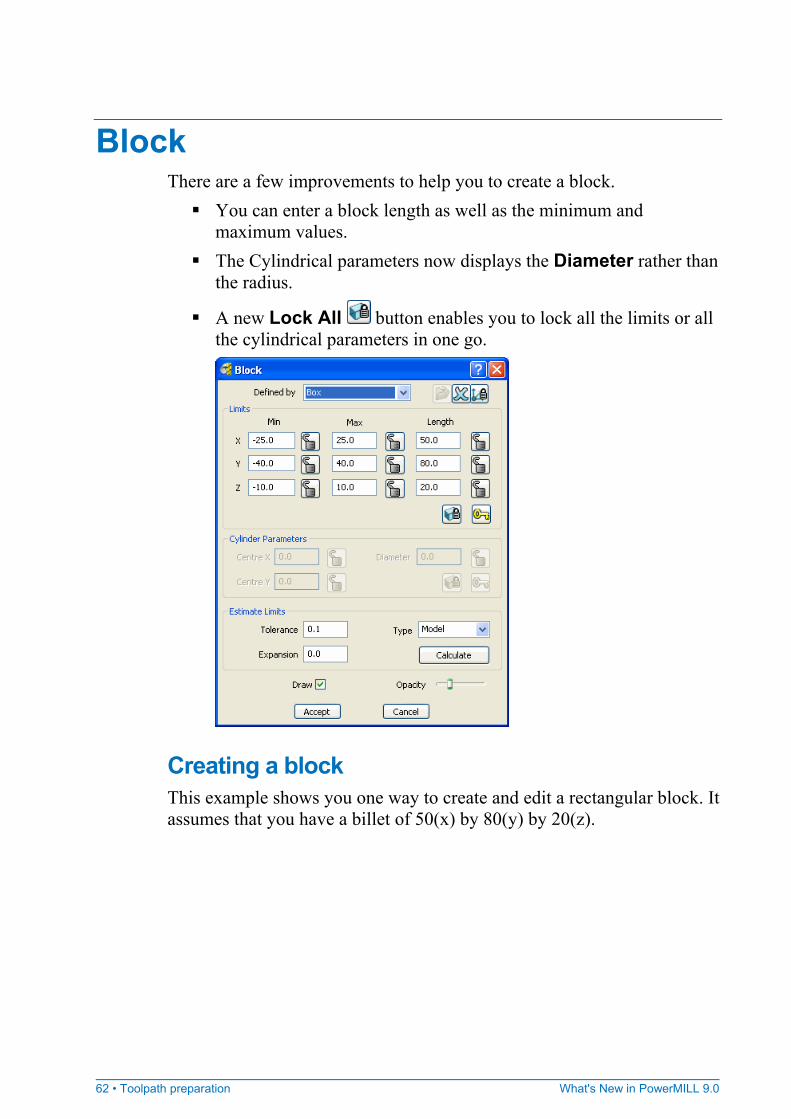
Block There are a few improvements to help you to create a block.
You can enter a block length as well as the minimum and maximum values.
The Cylindrical parameters now displays the Diameter rather than the radius.
A new Lock All button enables you to lock all the limits or all the cylindrical parameters in one go.
Creating a block This example shows you one way to create and edit a rectangular block. It assumes that you have a billet of 50(x) by 80(y) by 20(z).
What's New in PowerMILL 9.0 Toolpath preparation • 63
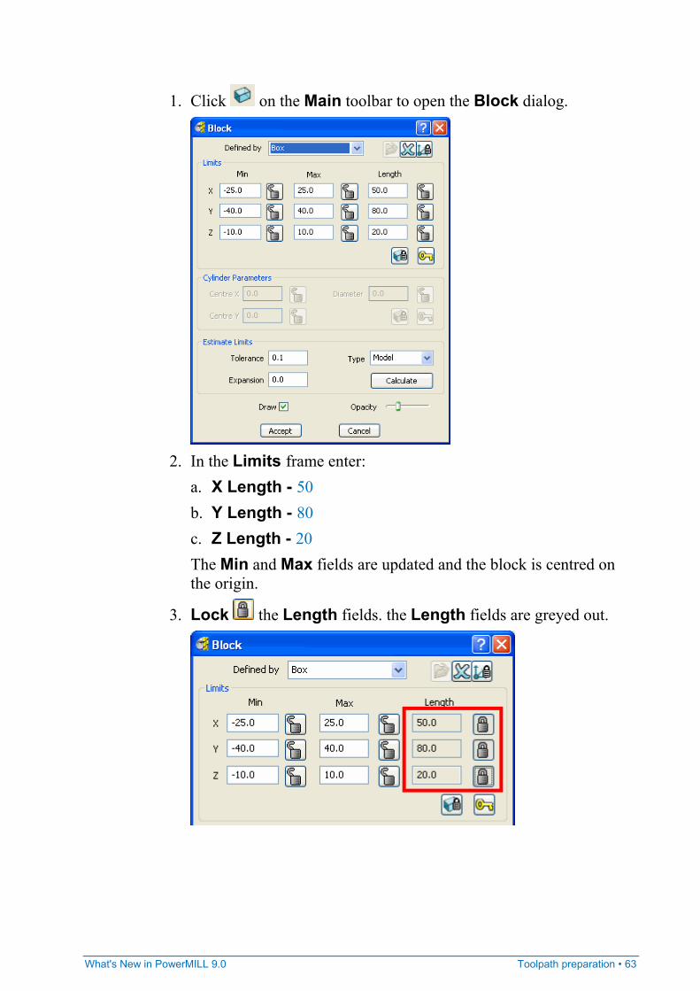
1. Click on the Main toolbar to open the Block dialog.
2. In the Limits frame enter:
a. X Length - 50 b. Y Length - 80 c. Z Length - 20 The Min and Max fields are updated and the block is centred on the origin.
3. Lock the Length fields. the Length fields are greyed out.
64 • Toolpath preparation What's New in PowerMILL 9.0
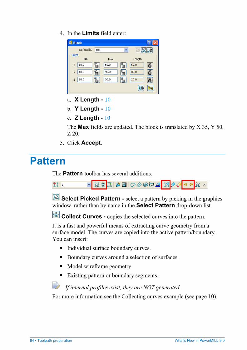
4. In the Limits field enter:
a. X Length - 10 b. Y Length - 10 c. Z Length - 10 The Max fields are updated. The block is translated by X 35, Y 50, Z 20.
5. Click Accept.
Pattern The Pattern toolbar has several additions.
Select Picked Pattern - select a pattern by picking in the graphics window, rather than by name in the Select Pattern drop-down list.
Collect Curves - copies the selected curves into the pattern. It is a fast and powerful means of extracting curve geometry from a surface model. The curves are copied into the active pattern/boundary. You can insert:
Individual surface boundary curves. Boundary curves around a selection of surfaces. Model wireframe geometry. Existing pattern or boundary segments.
If internal profiles exist, they are NOT generated. For more information see the Collecting curves example (see page 10).

What's New in PowerMILL 9.0 Toolpath preparation • 65
Curve Editor - displays the Curve Editor toolbar which allows you to create and edit patterns. The assumption is that you will extract curves from the model, by say, extracting curves at surface boundaries, and then modify the curve to create the exact pattern you need.
Undo - reverts the pattern to what it was before the last change.
Redo - reinstates the edit you have just undone.
66 • Toolpath preparation What's New in PowerMILL 9.0
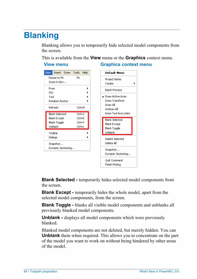
Blanking Blanking allows you to temporarily hide selected model components from the screen. This is available from the View menu or the Graphics context menu. View menu Graphics context menu
Blank Selected - temporarily hides selected model components from the screen. Blank Except - temporarily hides the whole model, apart from the selected model components, from the screen. Blank Toggle - blanks all visible model components and unblanks all previously blanked model components. Unblank - displays all model components which were previously blanked. Blanked model components are not deleted, but merely hidden. You can Unblank them when required. This allows you to concentrate on the part of the model you want to work on without being hindered by other areas of the model.
What's New in PowerMILL 9.0 Toolpath preparation • 67
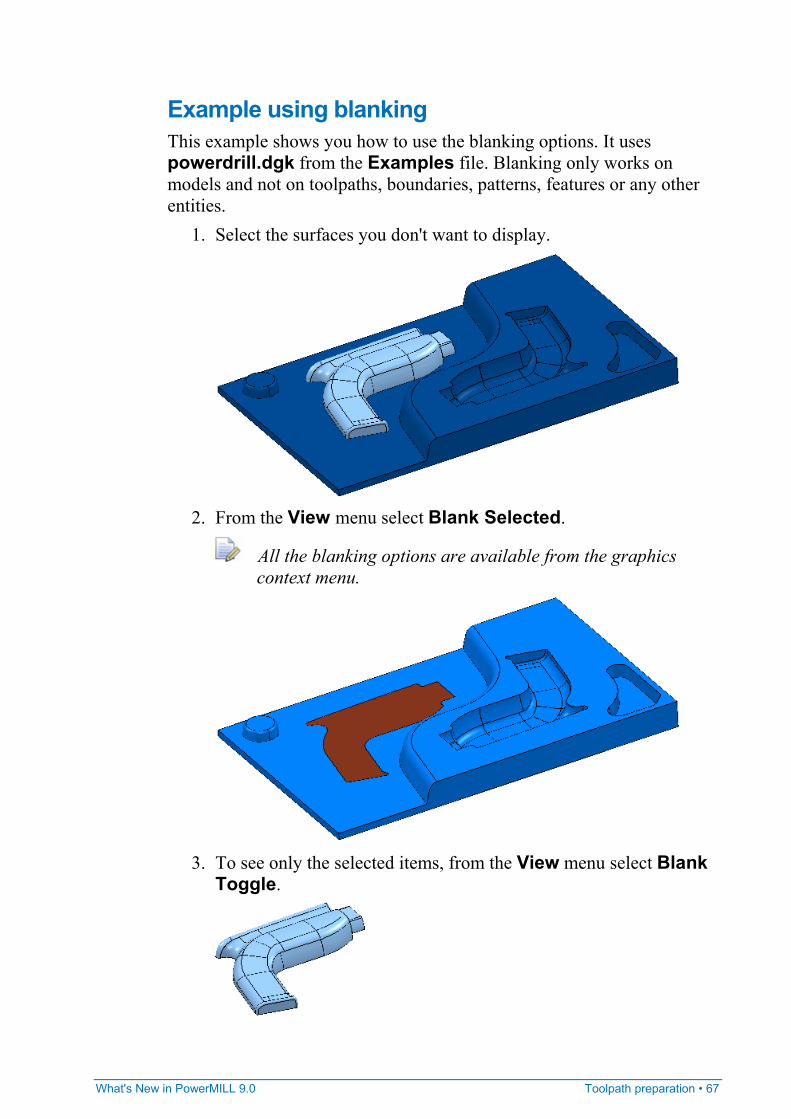
Example using blanking This example shows you how to use the blanking options. It uses powerdrill.dgk from the Examples file. Blanking only works on models and not on toolpaths, boundaries, patterns, features or any other entities.
1. Select the surfaces you don't want to display.
2. From the View menu select Blank Selected.
All the blanking options are available from the graphics context menu.
3. To see only the selected items, from the View menu select Blank
Toggle.
68 • Toolpath preparation What's New in PowerMILL 9.0
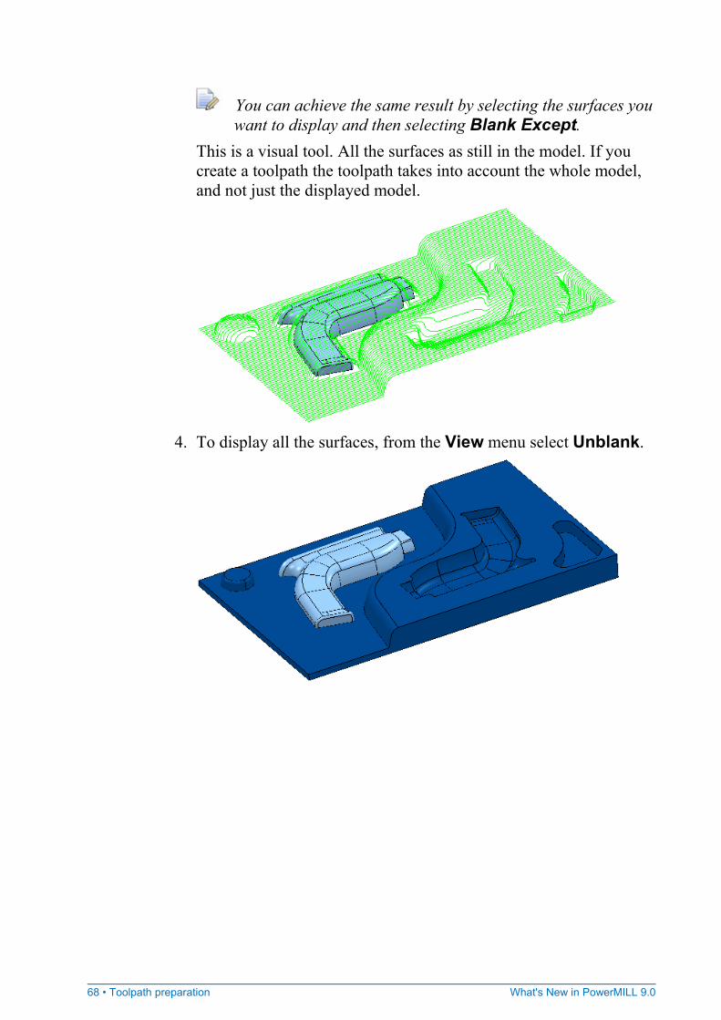
You can achieve the same result by selecting the surfaces you want to display and then selecting Blank Except.
This is a visual tool. All the surfaces as still in the model. If you create a toolpath the toolpath takes into account the whole model, and not just the displayed model.
4. To display all the surfaces, from the View menu select Unblank.
What's New in PowerMILL 9.0 Toolpath preparation • 69
General toolpath preparation improvements
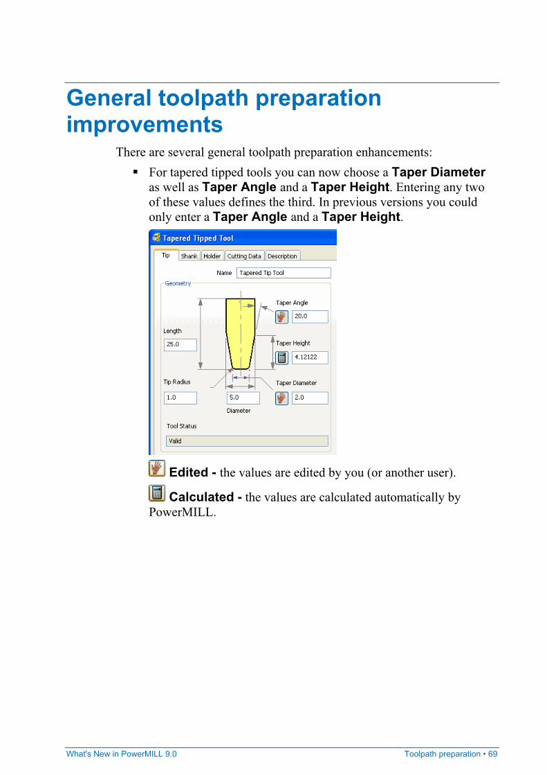
There are several general toolpath preparation enhancements: For tapered tipped tools you can now choose a Taper Diameter
as well as Taper Angle and a Taper Height. Entering any two of these values defines the third. In previous versions you could only enter a Taper Angle and a Taper Height.
Edited - the values are edited by you (or another user).
Calculated - the values are calculated automatically by PowerMILL.

70 • Toolpath preparation What's New in PowerMILL 9.0
The contact normal option is now on the Point Distribution dialog.
Previously it was on the Options dialog. Contact Normals - creates toolpaths with the contact normals details in them. This is essential when the machine tool performs the 3D cutter compensation and PowerMILL outputs I, J, K vectors to the tape file.
What's New in PowerMILL 9.0 Toolpath preparation • 71
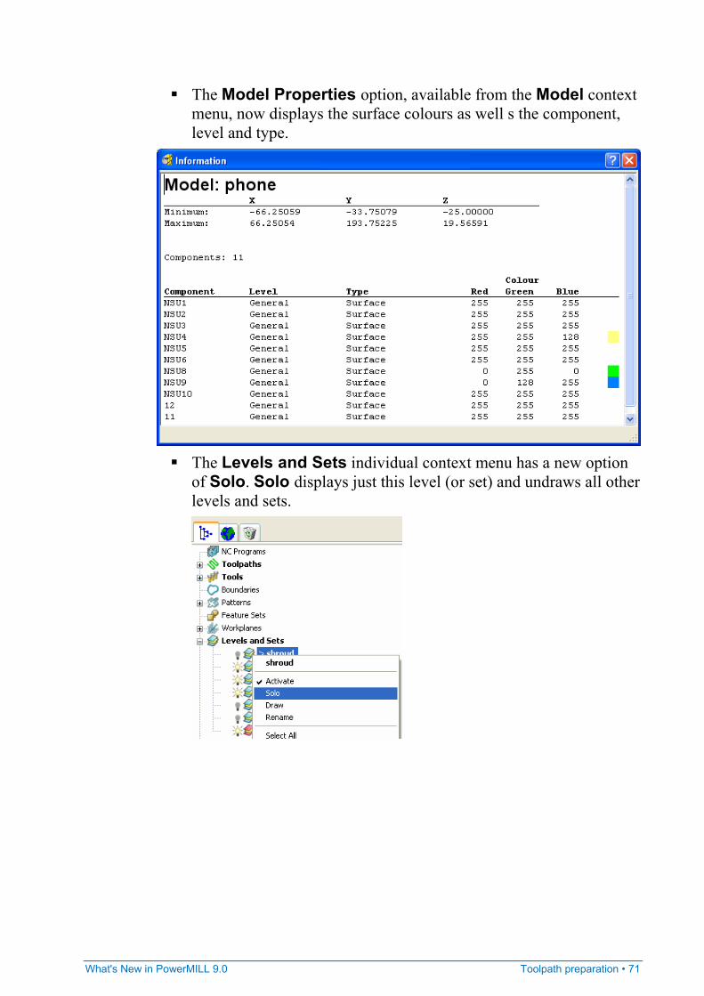
The Model Properties option, available from the Model context menu, now displays the surface colours as well s the component, level and type.
The Levels and Sets individual context menu has a new option
of Solo. Solo displays just this level (or set) and undraws all other levels and sets.
72 • Toolpath generation What's New in PowerMILL 9.0
Cutter compensation Cutter compensation is much improved and can now be applied to all 2.5D machining, area clearance, and drilling strategies when the toolpath is created.
Although cutter compensation can be applied to all drilling strategies, it makes a difference only if applied to Helical, Reverse Helical, Profile, or Thread Milling.
In PowerMILL 8.0 you could apply cutter compensation, but couldn't display the compensated toolpath. The compensated toolpath no longer replaces the actual tooltip toolpath. Now all toolpaths, simulation methods (including ViewMill) and stock models can display the cutter compensated toolpath (see page 74) correctly. The Draw Compensated Toolpath button on the Toolpath toolbar draws the toolpath (see page 76), showing where full radius compensation or wear compensation is applied.
Toolpath generation
What's New in PowerMILL 9.0 Toolpath generation • 73
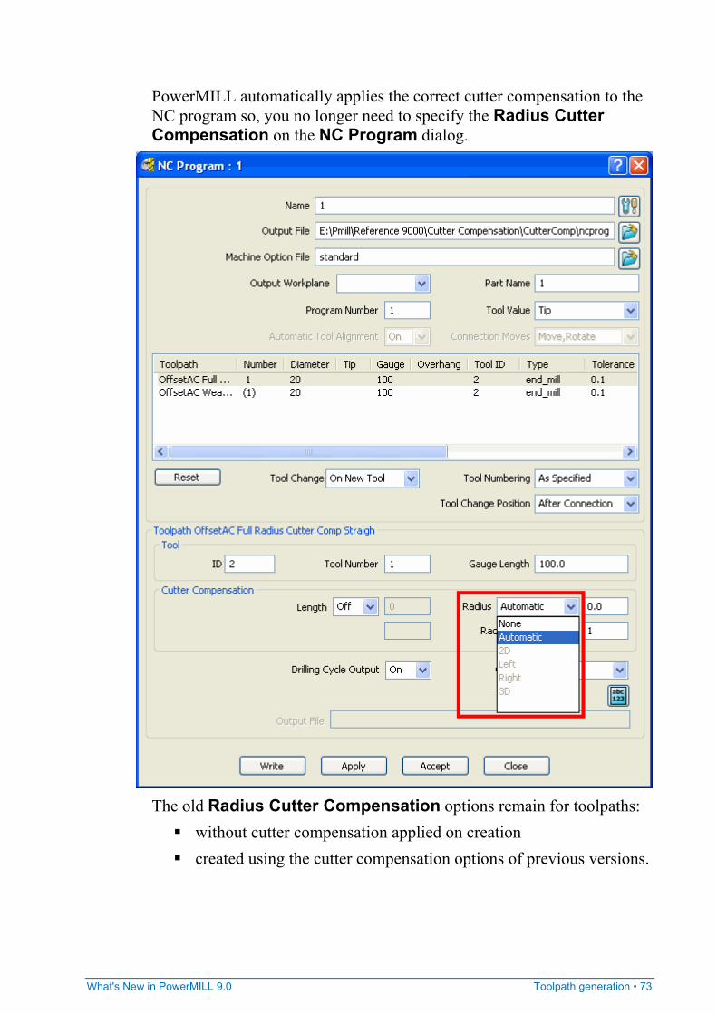
PowerMILL automatically applies the correct cutter compensation to the NC program so, you no longer need to specify the Radius Cutter Compensation on the NC Program dialog.
The old Radius Cutter Compensation options remain for toolpaths:
without cutter compensation applied on creation created using the cutter compensation options of previous versions.
74 • Toolpath generation What's New in PowerMILL 9.0
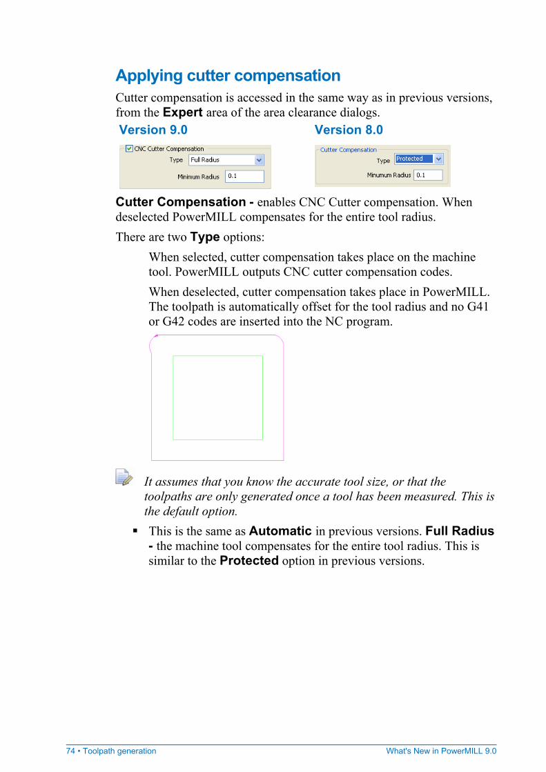
Applying cutter compensation Cutter compensation is accessed in the same way as in previous versions, from the Expert area of the area clearance dialogs. Version 9.0 Version 8.0
Cutter Compensation - enables CNC Cutter compensation. When deselected PowerMILL compensates for the entire tool radius. There are two Type options:
When selected, cutter compensation takes place on the machine tool. PowerMILL outputs CNC cutter compensation codes. When deselected, cutter compensation takes place in PowerMILL. The toolpath is automatically offset for the tool radius and no G41 or G42 codes are inserted into the NC program.
It assumes that you know the accurate tool size, or that the toolpaths are only generated once a tool has been measured. This is the default option.
This is the same as Automatic in previous versions. Full Radius - the machine tool compensates for the entire tool radius. This is similar to the Protected option in previous versions.
What's New in PowerMILL 9.0 Toolpath generation • 75
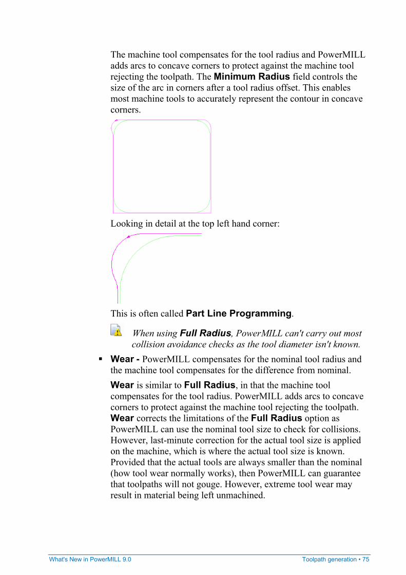
The machine tool compensates for the tool radius and PowerMILL adds arcs to concave corners to protect against the machine tool rejecting the toolpath. The Minimum Radius field controls the size of the arc in corners after a tool radius offset. This enables most machine tools to accurately represent the contour in concave corners.
Looking in detail at the top left hand corner:
This is often called Part Line Programming.
When using Full Radius, PowerMILL can't carry out most collision avoidance checks as the tool diameter isn't known.
Wear - PowerMILL compensates for the nominal tool radius and the machine tool compensates for the difference from nominal. Wear is similar to Full Radius, in that the machine tool compensates for the tool radius. PowerMILL adds arcs to concave corners to protect against the machine tool rejecting the toolpath. Wear corrects the limitations of the Full Radius option as PowerMILL can use the nominal tool size to check for collisions. However, last-minute correction for the actual tool size is applied on the machine, which is where the actual tool size is known. Provided that the actual tools are always smaller than the nominal (how tool wear normally works), then PowerMILL can guarantee that toolpaths will not gouge. However, extreme tool wear may result in material being left unmachined.
76 • Toolpath generation What's New in PowerMILL 9.0
Minimum Radius - the minimum radius of concave corners after applying tool radius cutter compensation. This avoids small arcs which some machine tools have difficulties processing. This option is available only when you have a Cutter Compensation Type of Full Radius.
The old option of Off is no longer available. It was of limited use since machine tools can't accurately represent the contour in concave corners, or when an arc exists that is less than the tool radius.
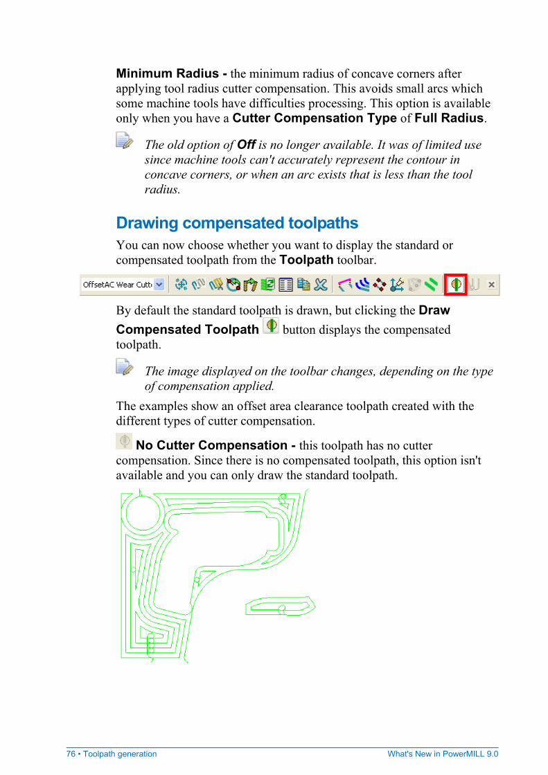
Drawing compensated toolpaths You can now choose whether you want to display the standard or compensated toolpath from the Toolpath toolbar.
By default the standard toolpath is drawn, but clicking the Draw Compensated Toolpath button displays the compensated toolpath.
The image displayed on the toolbar changes, depending on the type of compensation applied.
The examples show an offset area clearance toolpath created with the different types of cutter compensation.
No Cutter Compensation - this toolpath has no cutter compensation. Since there is no compensated toolpath, this option isn't available and you can only draw the standard toolpath.
What's New in PowerMILL 9.0 Toolpath generation • 77
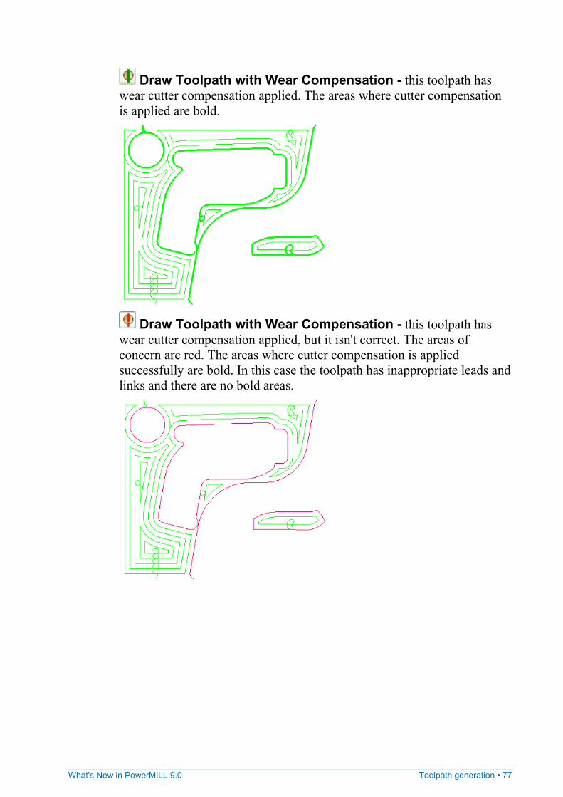
Draw Toolpath with Wear Compensation - this toolpath has wear cutter compensation applied. The areas where cutter compensation is applied are bold.
Draw Toolpath with Wear Compensation - this toolpath has wear cutter compensation applied, but it isn't correct. The areas of concern are red. The areas where cutter compensation is applied successfully are bold. In this case the toolpath has inappropriate leads and links and there are no bold areas.
78 • Toolpath generation What's New in PowerMILL 9.0
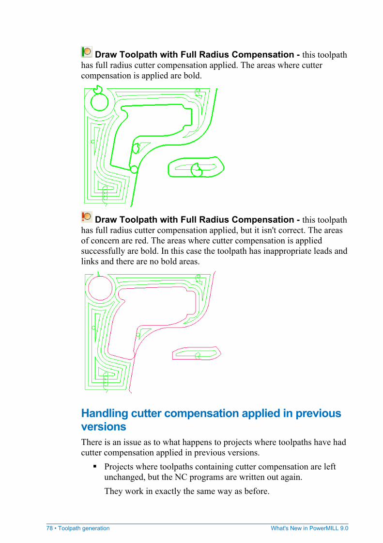
Draw Toolpath with Full Radius Compensation - this toolpath has full radius cutter compensation applied. The areas where cutter compensation is applied are bold.
Draw Toolpath with Full Radius Compensation - this toolpath has full radius cutter compensation applied, but it isn't correct. The areas of concern are red. The areas where cutter compensation is applied successfully are bold. In this case the toolpath has inappropriate leads and links and there are no bold areas.
Handling cutter compensation applied in previous versions There is an issue as to what happens to projects where toolpaths have had cutter compensation applied in previous versions.
Projects where toolpaths containing cutter compensation are left unchanged, but the NC programs are written out again. They work in exactly the same way as before.
What's New in PowerMILL 9.0 Toolpath generation • 79
Projects where toolpaths containing cutter compensation are recalculated. By default, they are recalculated as toolpaths without any cutter compensation and assume that the geometry is used as a drive curve, rather than representing the part. If this is not an acceptable solution you can add cutter compensation to the toolpath using the CNC Cutter Compensation Repair option.
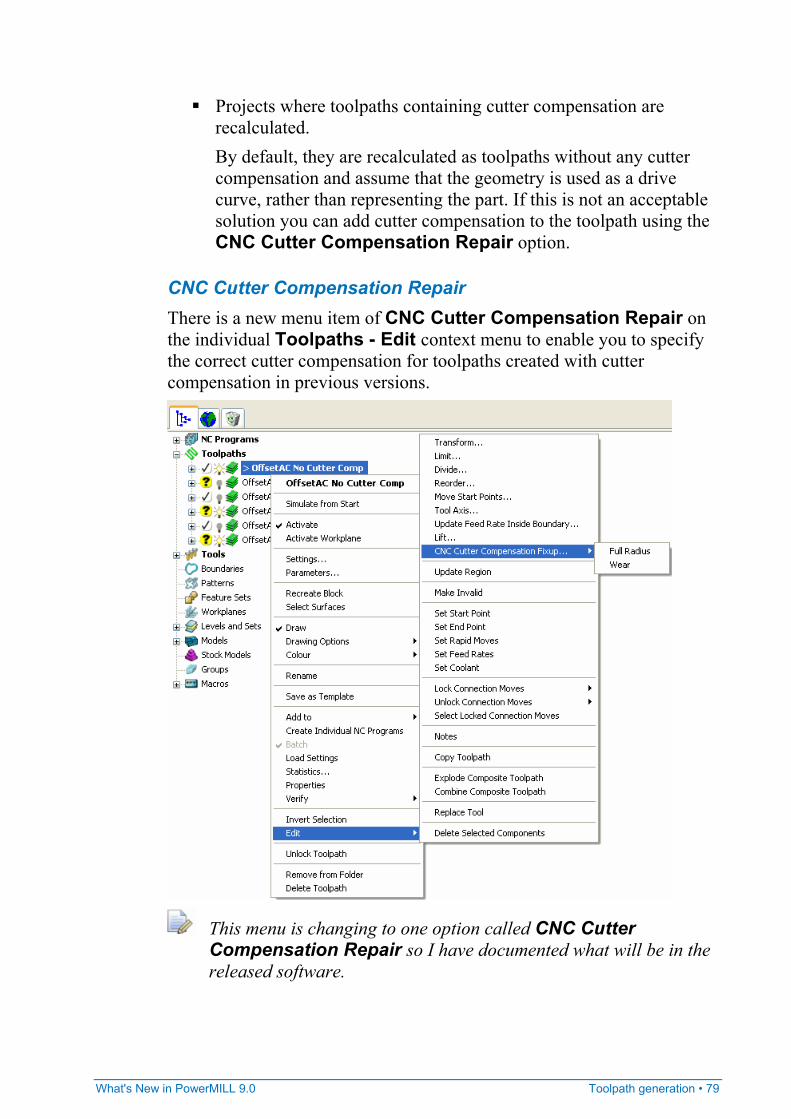
CNC Cutter Compensation Repair There is a new menu item of CNC Cutter Compensation Repair on the individual Toolpaths - Edit context menu to enable you to specify the correct cutter compensation for toolpaths created with cutter compensation in previous versions.
This menu is changing to one option called CNC Cutter Compensation Repair so I have documented what will be in the released software.
80 • Toolpath generation What's New in PowerMILL 9.0
Sets the geometry position to Part and the cutter compensation to Full Radius. If you don't repair toolpaths that have had cutter compensation applied in version 8.0 or earlier, when the toolpaths are recalculated, they have no toolpath cutter compensation applied and the geometry is used as a drive curve, rather than representing the part. This happens as PowerMILL doesn't know whether the cutter compensation required is Full Radius or Wear as there was no distinction between these two options in previous versions.
The geometry position can be either: Part - the geometry represents the part. Toolpath - the geometry represents the drive curve.
What's New in PowerMILL 9.0 Toolpath generation • 81
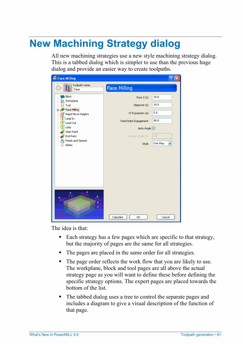
New Machining Strategy dialog All new machining strategies use a new style machining strategy dialog. This is a tabbed dialog which is simpler to use than the previous huge dialog and provide an easier way to create toolpaths.
The idea is that:
Each strategy has a few pages which are specific to that strategy, but the majority of pages are the same for all strategies.
The pages are placed in the same order for all strategies. The page order reflects the work flow that you are likely to use.
The workplane, block and tool pages are all above the actual strategy page as you will want to define these before defining the specific strategy options. The expert pages are placed towards the bottom of the list.
The tabbed dialog uses a tree to control the separate pages and includes a diagram to give a visual description of the function of that page.
82 • Toolpath generation What's New in PowerMILL 9.0
The tree in the tabbed dialog looks the same as that in the explorer, it has the same icons, labels and order.
Common toolpath creation controls for new strategies All the various machining strategy dialogs share many common controls.
Recycle Toolpath - enables you to edit the parameters of the toolpath you have just created, and then recalculate it. The new toolpath will overwrite the previous one.
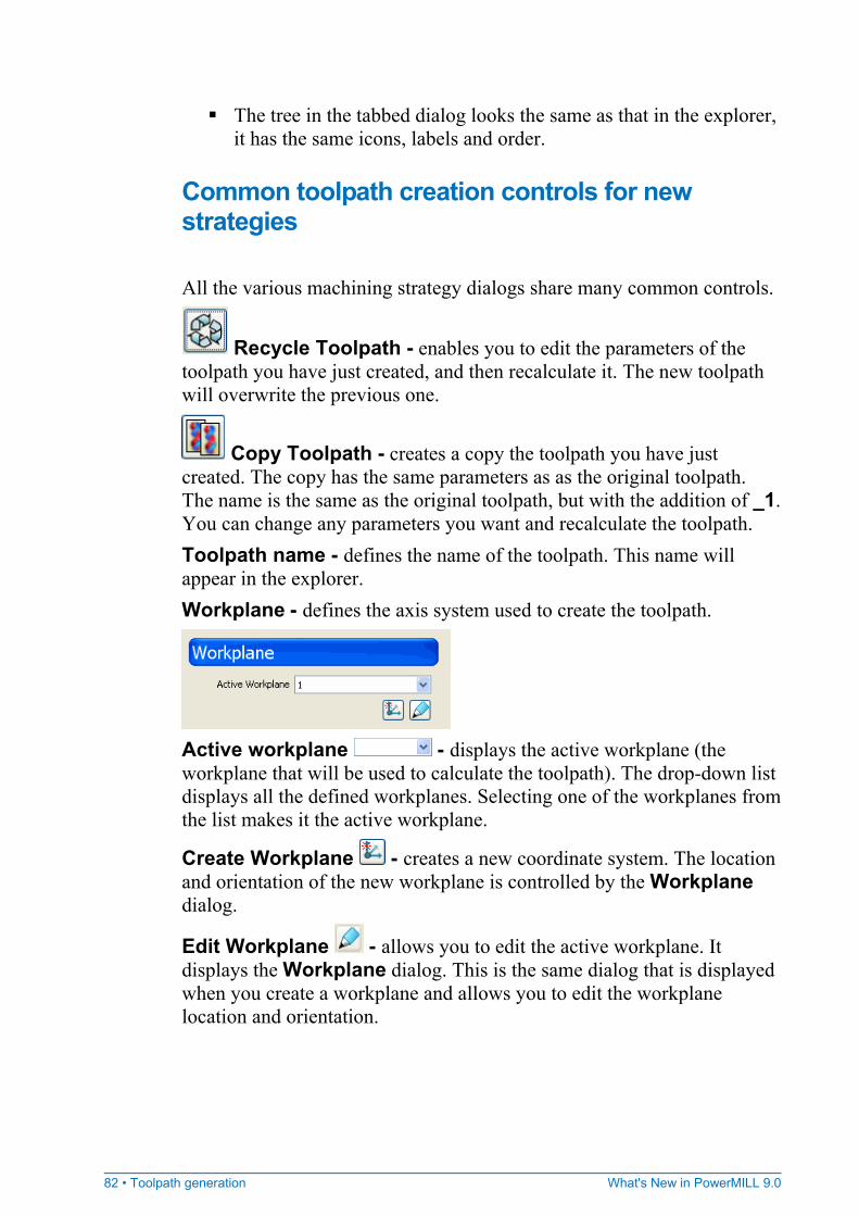
Copy Toolpath - creates a copy the toolpath you have just created. The copy has the same parameters as as the original toolpath. The name is the same as the original toolpath, but with the addition of _1. You can change any parameters you want and recalculate the toolpath. Toolpath name - defines the name of the toolpath. This name will appear in the explorer. Workplane - defines the axis system used to create the toolpath.
Active workplane - displays the active workplane (the workplane that will be used to calculate the toolpath). The drop-down list displays all the defined workplanes. Selecting one of the workplanes from the list makes it the active workplane.
Create Workplane - creates a new coordinate system. The location and orientation of the new workplane is controlled by the Workplane dialog.
Edit Workplane - allows you to edit the active workplane. It displays the Workplane dialog. This is the same dialog that is displayed when you create a workplane and allows you to edit the workplane location and orientation.
What's New in PowerMILL 9.0 Toolpath generation • 83
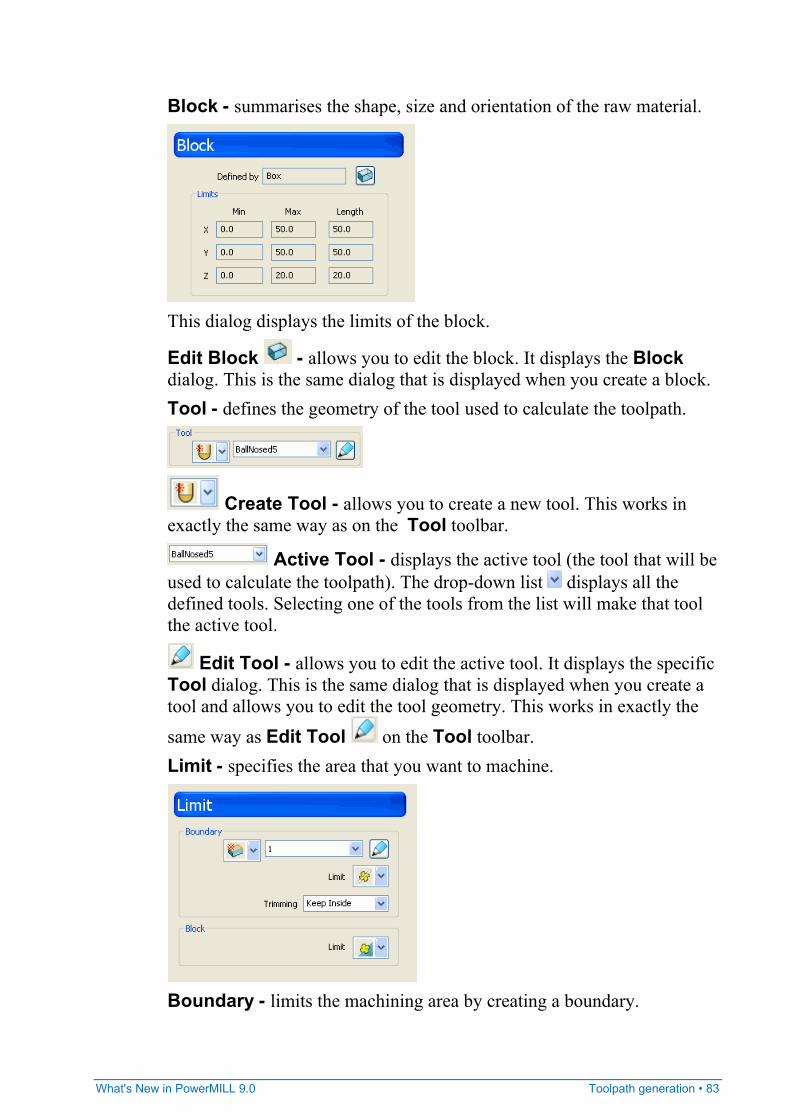
Block - summarises the shape, size and orientation of the raw material.
This dialog displays the limits of the block.
Edit Block - allows you to edit the block. It displays the Block dialog. This is the same dialog that is displayed when you create a block. Tool - defines the geometry of the tool used to calculate the toolpath.
Create Tool - allows you to create a new tool. This works in exactly the same way as on the Tool toolbar.
Active Tool - displays the active tool (the tool that will be used to calculate the toolpath). The drop-down list displays all the defined tools. Selecting one of the tools from the list will make that tool the active tool.
Edit Tool - allows you to edit the active tool. It displays the specific Tool dialog. This is the same dialog that is displayed when you create a tool and allows you to edit the tool geometry. This works in exactly the
same way as Edit Tool on the Tool toolbar. Limit - specifies the area that you want to machine.
Boundary - limits the machining area by creating a boundary.
84 • Toolpath generation What's New in PowerMILL 9.0
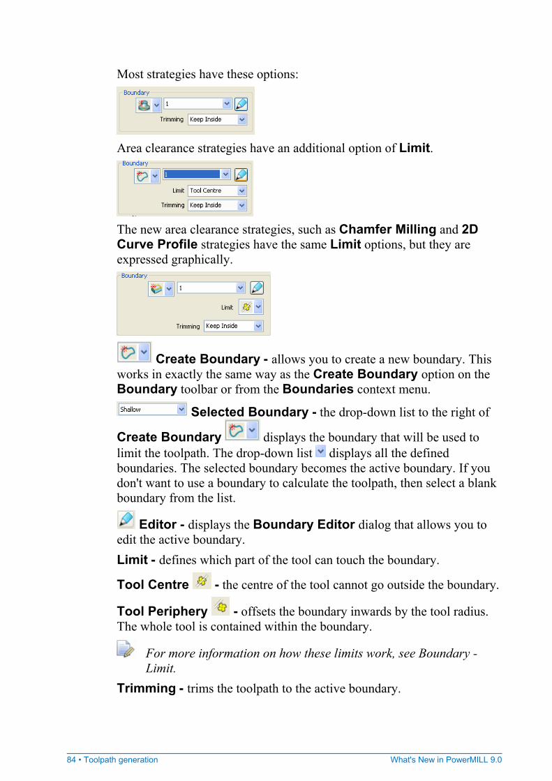
Most strategies have these options:
Area clearance strategies have an additional option of Limit.
The new area clearance strategies, such as Chamfer Milling and 2D Curve Profile strategies have the same Limit options, but they are expressed graphically.
Create Boundary - allows you to create a new boundary. This works in exactly the same way as the Create Boundary option on the Boundary toolbar or from the Boundaries context menu.
Selected Boundary - the drop-down list to the right of
Create Boundary displays the boundary that will be used to limit the toolpath. The drop-down list displays all the defined boundaries. The selected boundary becomes the active boundary. If you don't want to use a boundary to calculate the toolpath, then select a blank boundary from the list.
Editor - displays the Boundary Editor dialog that allows you to edit the active boundary. Limit - defines which part of the tool can touch the boundary.
Tool Centre - the centre of the tool cannot go outside the boundary.
Tool Periphery - offsets the boundary inwards by the tool radius. The whole tool is contained within the boundary.
For more information on how these limits work, see Boundary - Limit.
Trimming - trims the toolpath to the active boundary.
What's New in PowerMILL 9.0 Toolpath generation • 85
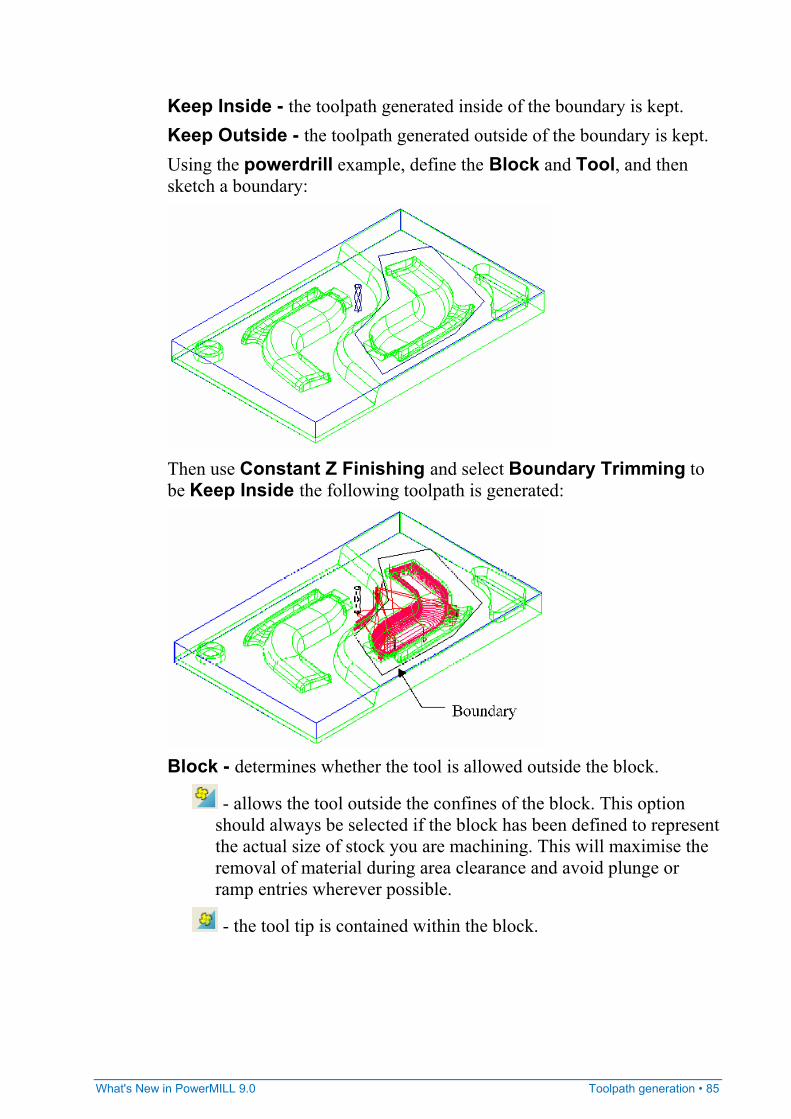
Keep Inside - the toolpath generated inside of the boundary is kept. Keep Outside - the toolpath generated outside of the boundary is kept. Using the powerdrill example, define the Block and Tool, and then sketch a boundary:
Then use Constant Z Finishing and select Boundary Trimming to be Keep Inside the following toolpath is generated:
Block - determines whether the tool is allowed outside the block.
- allows the tool outside the confines of the block. This option should always be selected if the block has been defined to represent the actual size of stock you are machining. This will maximise the removal of material during area clearance and avoid plunge or ramp entries wherever possible.
- the tool tip is contained within the block.
86 • Toolpath generation What's New in PowerMILL 9.0
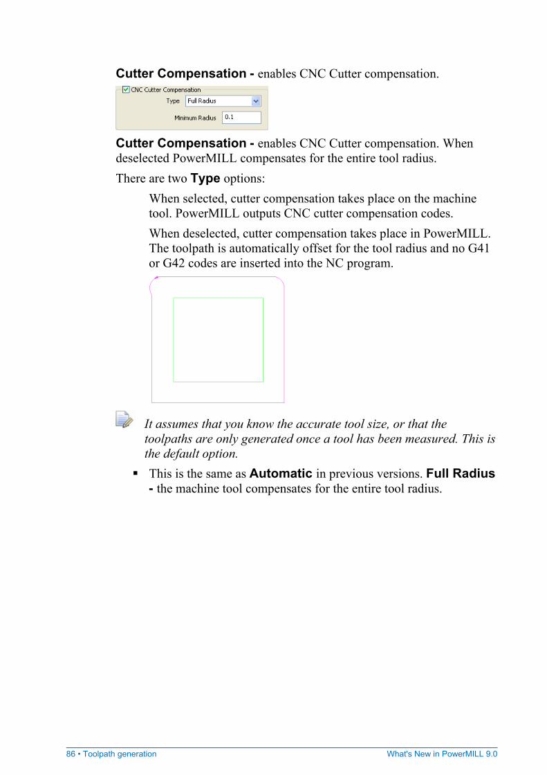
Cutter Compensation - enables CNC Cutter compensation.
Cutter Compensation - enables CNC Cutter compensation. When deselected PowerMILL compensates for the entire tool radius. There are two Type options:
When selected, cutter compensation takes place on the machine tool. PowerMILL outputs CNC cutter compensation codes. When deselected, cutter compensation takes place in PowerMILL. The toolpath is automatically offset for the tool radius and no G41 or G42 codes are inserted into the NC program.
It assumes that you know the accurate tool size, or that the toolpaths are only generated once a tool has been measured. This is the default option.
This is the same as Automatic in previous versions. Full Radius - the machine tool compensates for the entire tool radius.
What's New in PowerMILL 9.0 Toolpath generation • 87
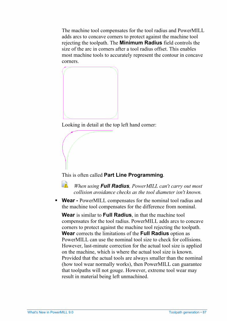
The machine tool compensates for the tool radius and PowerMILL adds arcs to concave corners to protect against the machine tool rejecting the toolpath. The Minimum Radius field controls the size of the arc in corners after a tool radius offset. This enables most machine tools to accurately represent the contour in concave corners.
Looking in detail at the top left hand corner:
This is often called Part Line Programming.
When using Full Radius, PowerMILL can't carry out most collision avoidance checks as the tool diameter isn't known.
Wear - PowerMILL compensates for the nominal tool radius and the machine tool compensates for the difference from nominal. Wear is similar to Full Radius, in that the machine tool compensates for the tool radius. PowerMILL adds arcs to concave corners to protect against the machine tool rejecting the toolpath. Wear corrects the limitations of the Full Radius option as PowerMILL can use the nominal tool size to check for collisions. However, last-minute correction for the actual tool size is applied on the machine, which is where the actual tool size is known. Provided that the actual tools are always smaller than the nominal (how tool wear normally works), then PowerMILL can guarantee that toolpaths will not gouge. However, extreme tool wear may result in material being left unmachined.
88 • Toolpath generation What's New in PowerMILL 9.0
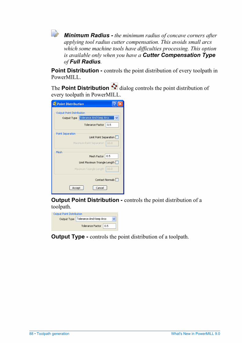
Minimum Radius - the minimum radius of concave corners after applying tool radius cutter compensation. This avoids small arcs which some machine tools have difficulties processing. This option is available only when you have a Cutter Compensation Type of Full Radius.
Point Distribution - controls the point distribution of every toolpath in PowerMILL.
The Point Distribution dialog controls the point distribution of every toolpath in PowerMILL.
Output Point Distribution - controls the point distribution of a toolpath.
Output Type - controls the point distribution of a toolpath.
What's New in PowerMILL 9.0 Toolpath generation • 89
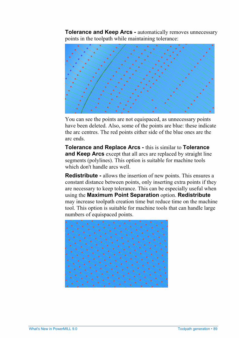
Tolerance and Keep Arcs - automatically removes unnecessary points in the toolpath while maintaining tolerance:
You can see the points are not equispaced, as unnecessary points have been deleted. Also, some of the points are blue: these indicate the arc centres. The red points either side of the blue ones are the arc ends. Tolerance and Replace Arcs - this is similar to Tolerance and Keep Arcs except that all arcs are replaced by straight line segments (polylines). This option is suitable for machine tools which don't handle arcs well. Redistribute - allows the insertion of new points. This ensures a constant distance between points, only inserting extra points if they are necessary to keep tolerance. This can be especially useful when using the Maximum Point Separation option. Redistribute may increase toolpath creation time but reduce time on the machine tool. This option is suitable for machine tools that can handle large numbers of equispaced points.
90 • Toolpath generation What's New in PowerMILL 9.0
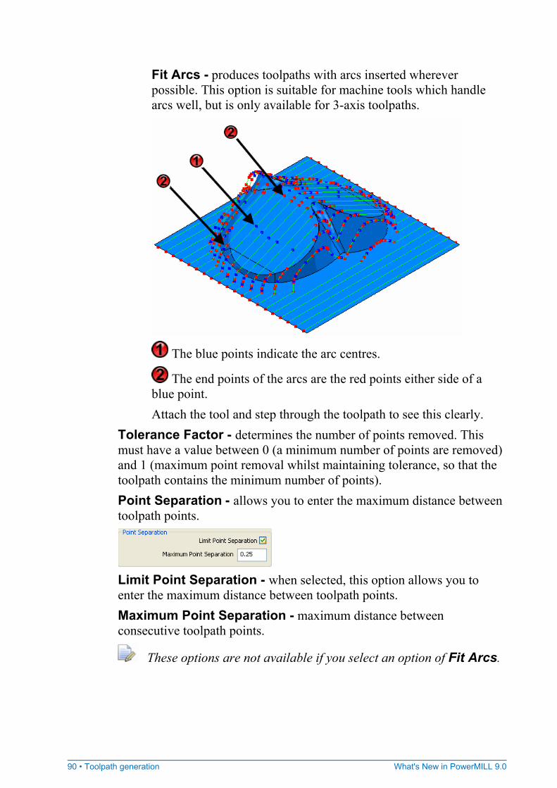
Fit Arcs - produces toolpaths with arcs inserted wherever possible. This option is suitable for machine tools which handle arcs well, but is only available for 3-axis toolpaths.
The blue points indicate the arc centres.
The end points of the arcs are the red points either side of a blue point. Attach the tool and step through the toolpath to see this clearly.
Tolerance Factor - determines the number of points removed. This must have a value between 0 (a minimum number of points are removed) and 1 (maximum point removal whilst maintaining tolerance, so that the toolpath contains the minimum number of points). Point Separation - allows you to enter the maximum distance between toolpath points.
Limit Point Separation - when selected, this option allows you to enter the maximum distance between toolpath points. Maximum Point Separation - maximum distance between consecutive toolpath points.
These options are not available if you select an option of Fit Arcs.
What's New in PowerMILL 9.0 Toolpath generation • 91
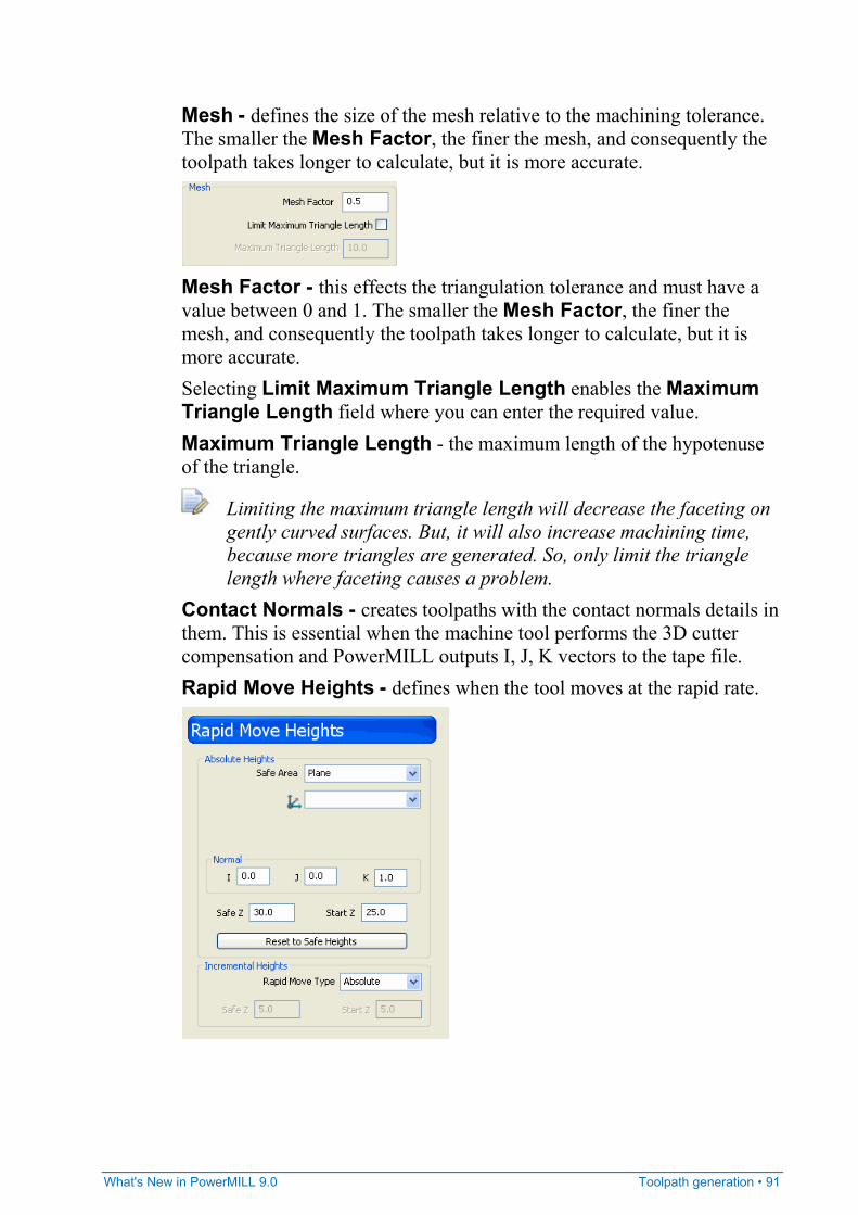
Mesh - defines the size of the mesh relative to the machining tolerance. The smaller the Mesh Factor, the finer the mesh, and consequently the toolpath takes longer to calculate, but it is more accurate.
Mesh Factor - this effects the triangulation tolerance and must have a value between 0 and 1. The smaller the Mesh Factor, the finer the mesh, and consequently the toolpath takes longer to calculate, but it is more accurate. Selecting Limit Maximum Triangle Length enables the Maximum Triangle Length field where you can enter the required value. Maximum Triangle Length - the maximum length of the hypotenuse of the triangle.
Limiting the maximum triangle length will decrease the faceting on gently curved surfaces. But, it will also increase machining time, because more triangles are generated. So, only limit the triangle length where faceting causes a problem.
Contact Normals - creates toolpaths with the contact normals details in them. This is essential when the machine tool performs the 3D cutter compensation and PowerMILL outputs I, J, K vectors to the tape file. Rapid Move Heights - defines when the tool moves at the rapid rate.
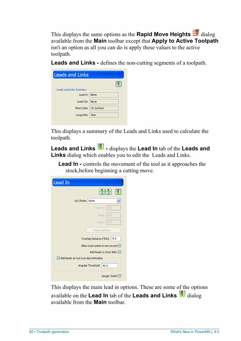
92 • Toolpath generation What's New in PowerMILL 9.0
This displays the same options as the Rapid Move Heights dialog available from the Main toolbar except that Apply to Active Toolpath isn't an option as all you can do is apply these values to the active toolpath. Leads and Links - defines the non-cutting segments of a toolpath.
This displays a summary of the Leads and Links used to calculate the toolpath.
Leads and Links - displays the Lead In tab of the Leads and Links dialog which enables you to edit the Leads and Links.
Lead In - controls the movement of the tool as it approaches the stock,before beginning a cutting move.
This displays the main lead in options. These are some of the options available on the Lead In tab of the Leads and Links dialog available from the Main toolbar.
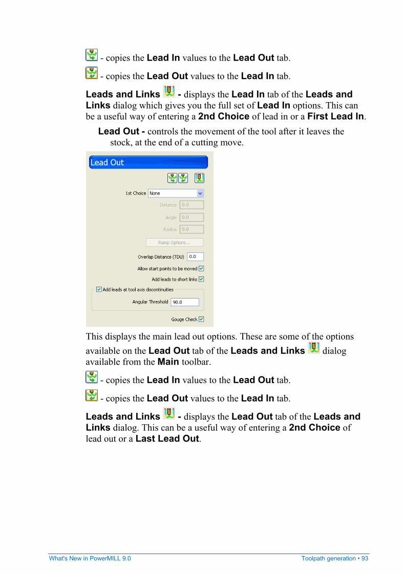
What's New in PowerMILL 9.0 Toolpath generation • 93
- copies the Lead In values to the Lead Out tab.
- copies the Lead Out values to the Lead In tab.
Leads and Links - displays the Lead In tab of the Leads and Links dialog which gives you the full set of Lead In options. This can be a useful way of entering a 2nd Choice of lead in or a First Lead In.
Lead Out - controls the movement of the tool after it leaves the stock, at the end of a cutting move.
This displays the main lead out options. These are some of the options available on the Lead Out tab of the Leads and Links dialog available from the Main toolbar.
- copies the Lead In values to the Lead Out tab.
- copies the Lead Out values to the Lead In tab.
Leads and Links - displays the Lead Out tab of the Leads and Links dialog. This can be a useful way of entering a 2nd Choice of lead out or a Last Lead Out.
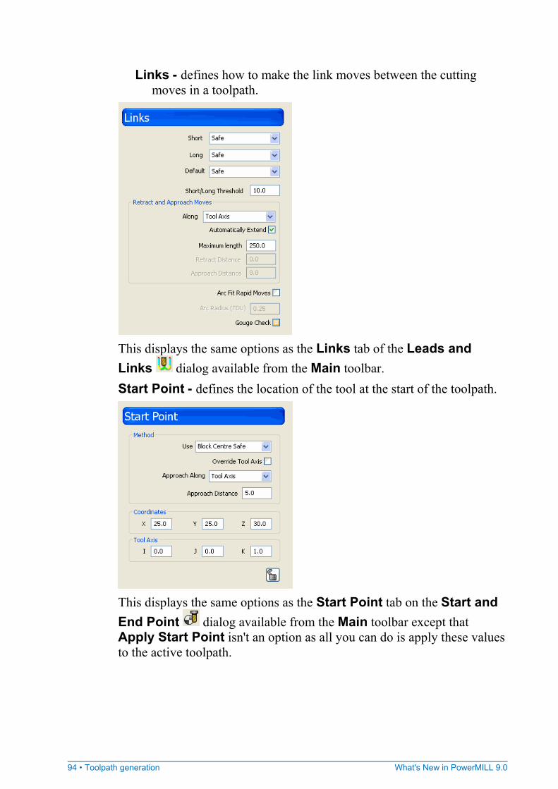
94 • Toolpath generation What's New in PowerMILL 9.0
Links - defines how to make the link moves between the cutting moves in a toolpath.
This displays the same options as the Links tab of the Leads and Links dialog available from the Main toolbar. Start Point - defines the location of the tool at the start of the toolpath.
This displays the same options as the Start Point tab on the Start and End Point dialog available from the Main toolbar except that Apply Start Point isn't an option as all you can do is apply these values to the active toolpath.
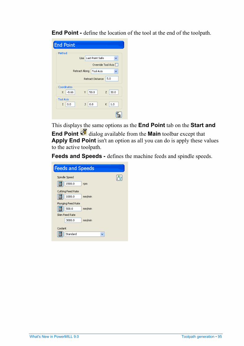
What's New in PowerMILL 9.0 Toolpath generation • 95
End Point - define the location of the tool at the end of the toolpath.
This displays the same options as the End Point tab on the Start and End Point dialog available from the Main toolbar except that Apply End Point isn't an option as all you can do is apply these values to the active toolpath. Feeds and Speeds - defines the machine feeds and spindle speeds.
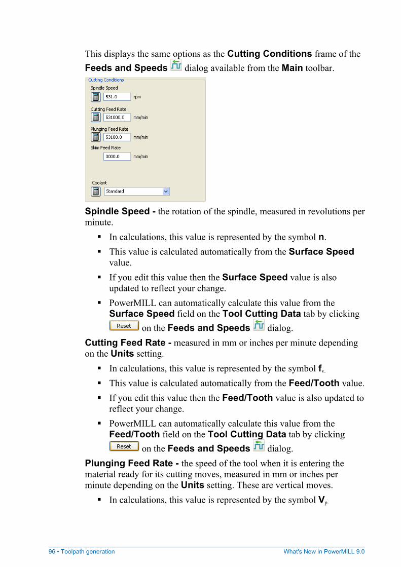
96 • Toolpath generation What's New in PowerMILL 9.0
This displays the same options as the Cutting Conditions frame of the Feeds and Speeds dialog available from the Main toolbar.
Spindle Speed - the rotation of the spindle, measured in revolutions per minute.
In calculations, this value is represented by the symbol n. This value is calculated automatically from the Surface Speed
value. If you edit this value then the Surface Speed value is also
updated to reflect your change. PowerMILL can automatically calculate this value from the
Surface Speed field on the Tool Cutting Data tab by clicking on the Feeds and Speeds dialog.
Cutting Feed Rate - measured in mm or inches per minute depending on the Units setting.
In calculations, this value is represented by the symbol fv. This value is calculated automatically from the Feed/Tooth value. If you edit this value then the Feed/Tooth value is also updated to
reflect your change. PowerMILL can automatically calculate this value from the
Feed/Tooth field on the Tool Cutting Data tab by clicking on the Feeds and Speeds dialog.
Plunging Feed Rate - the speed of the tool when it is entering the material ready for its cutting moves, measured in mm or inches per minute depending on the Units setting. These are vertical moves.
In calculations, this value is represented by the symbol Vp.
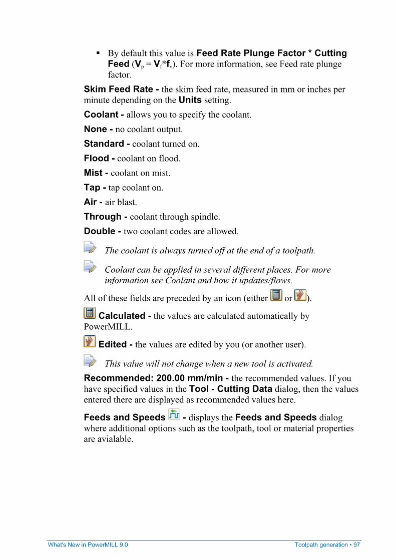
What's New in PowerMILL 9.0 Toolpath generation • 97
By default this value is Feed Rate Plunge Factor * Cutting Feed (Vp = Vf*fv). For more information, see Feed rate plunge factor.
Skim Feed Rate - the skim feed rate, measured in mm or inches per minute depending on the Units setting. Coolant - allows you to specify the coolant. None - no coolant output. Standard - coolant turned on. Flood - coolant on flood. Mist - coolant on mist. Tap - tap coolant on. Air - air blast. Through - coolant through spindle. Double - two coolant codes are allowed.
The coolant is always turned off at the end of a toolpath.
Coolant can be applied in several different places. For more information see Coolant and how it updates/flows.
All of these fields are preceded by an icon (either or ).
Calculated - the values are calculated automatically by PowerMILL.
Edited - the values are edited by you (or another user).
This value will not change when a new tool is activated. Recommended: 200.00 mm/min - the recommended values. If you have specified values in the Tool - Cutting Data dialog, then the values entered there are displayed as recommended values here.
Feeds and Speeds - displays the Feeds and Speeds dialog where additional options such as the toolpath, tool or material properties are avialable.
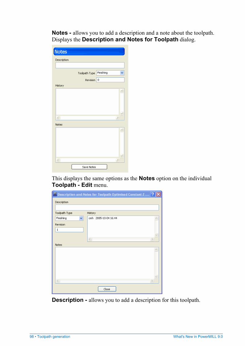
98 • Toolpath generation What's New in PowerMILL 9.0
Notes - allows you to add a description and a note about the toolpath. Displays the Description and Notes for Toolpath dialog.
This displays the same options as the Notes option on the individual Toolpath - Edit menu.
Description - allows you to add a description for this toolpath.
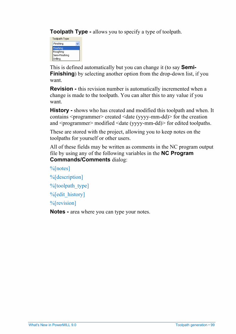
What's New in PowerMILL 9.0 Toolpath generation • 99
Toolpath Type - allows you to specify a type of toolpath.
This is defined automatically but you can change it (to say Semi-Finishing) by selecting another option from the drop-down list, if you want. Revision - this revision number is automatically incremented when a change is made to the toolpath. You can alter this to any value if you want. History - shows who has created and modified this toolpath and when. It contains <programmer> created <date (yyyy-mm-dd)> for the creation and <programmer> modified <date (yyyy-mm-dd)> for edited toolpaths. These are stored with the project, allowing you to keep notes on the toolpaths for yourself or other users. All of these fields may be written as comments in the NC program output file by using any of the following variables in the NC Program Commands/Comments dialog: %[notes] %[description] %[toolpath_type] %[edit_history] %[revision] Notes - area where you can type your notes.
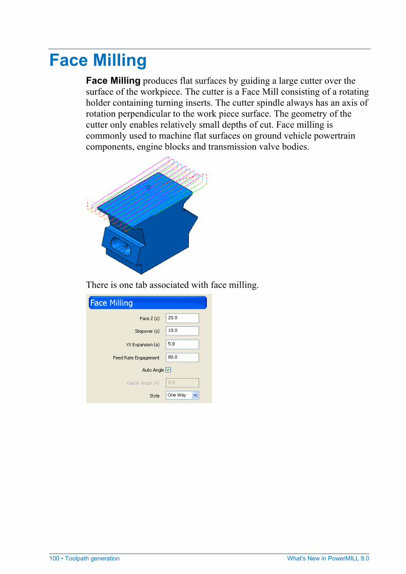
100 • Toolpath generation What's New in PowerMILL 9.0
Face Milling Face Milling produces flat surfaces by guiding a large cutter over the surface of the workpiece. The cutter is a Face Mill consisting of a rotating holder containing turning inserts. The cutter spindle always has an axis of rotation perpendicular to the work piece surface. The geometry of the cutter only enables relatively small depths of cut. Face milling is commonly used to machine flat surfaces on ground vehicle powertrain components, engine blocks and transmission valve bodies.
There is one tab associated with face milling.
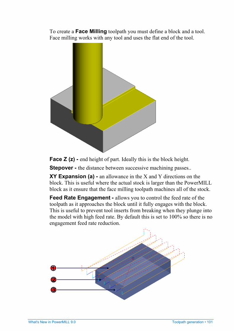
What's New in PowerMILL 9.0 Toolpath generation • 101
To create a Face Milling toolpath you must define a block and a tool. Face milling works with any tool and uses the flat end of the tool.
Face Z (z) - end height of part. Ideally this is the block height. Stepover - the distance between successive machining passes.. XY Expansion (a) - an allowance in the X and Y directions on the block. This is useful where the actual stock is larger than the PowerMILL block as it ensure that the face milling toolpath machines all of the stock. Feed Rate Engagement - allows you to control the feed rate of the toolpath as it approaches the block until it fully engages with the block. This is useful to prevent tool inserts from breaking when they plunge into the model with high feed rate. By default this is set to 100% so there is no engagement feed rate reduction.
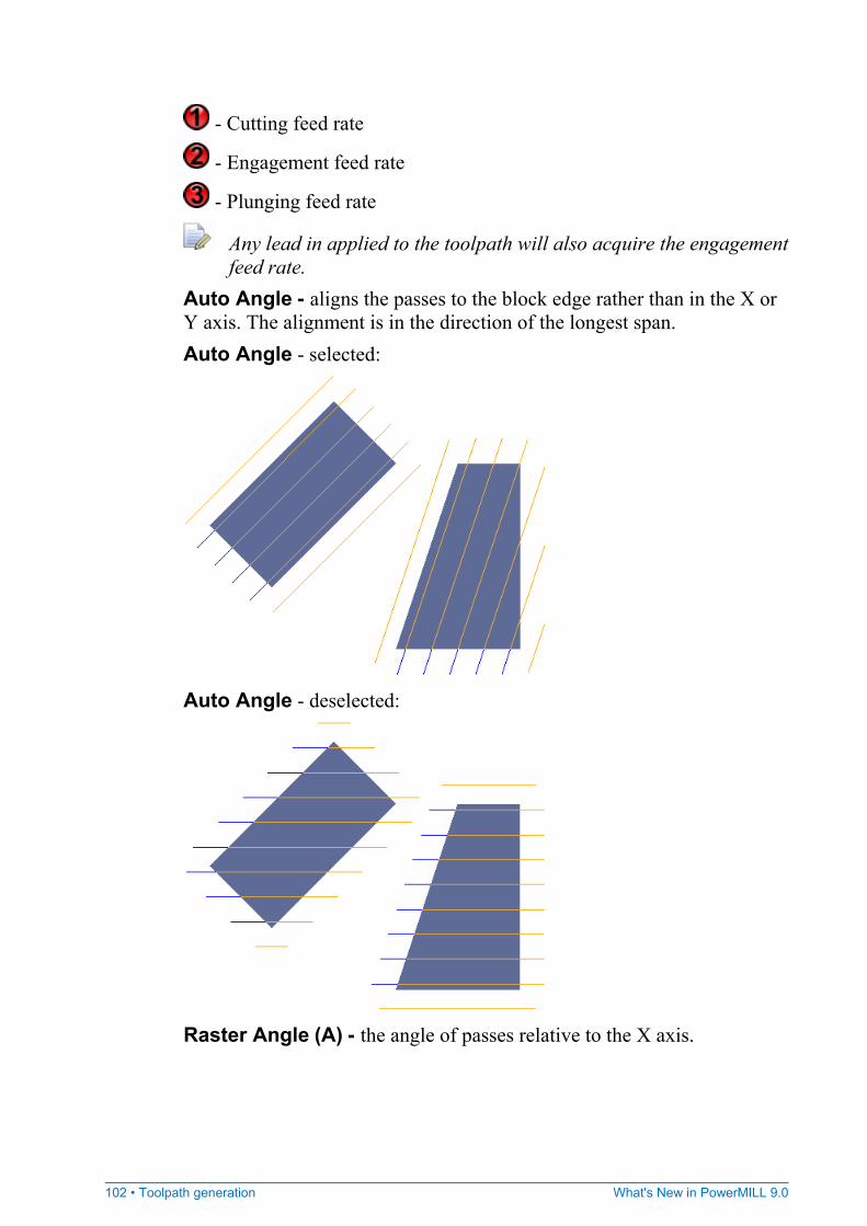
102 • Toolpath generation What's New in PowerMILL 9.0
- Cutting feed rate
- Engagement feed rate
- Plunging feed rate
Any lead in applied to the toolpath will also acquire the engagement feed rate.
Auto Angle - aligns the passes to the block edge rather than in the X or Y axis. The alignment is in the direction of the longest span. Auto Angle - selected:
Auto Angle - deselected:
Raster Angle (A) - the angle of passes relative to the X axis.
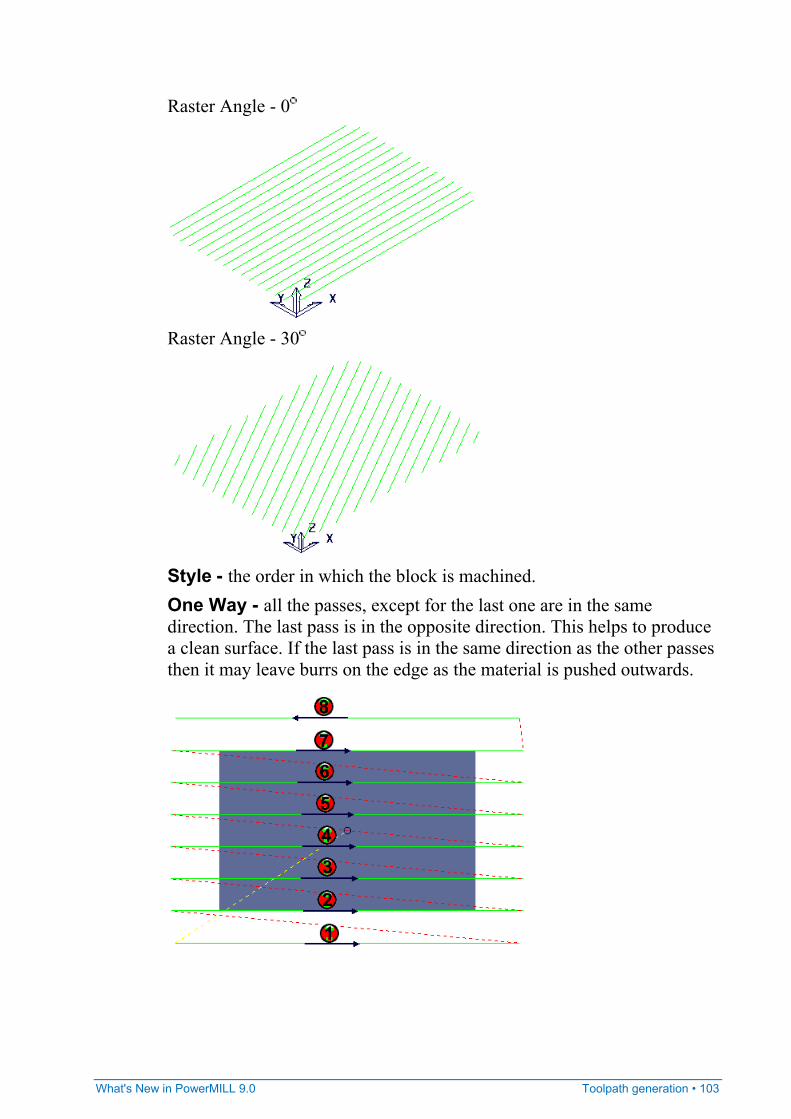
What's New in PowerMILL 9.0 Toolpath generation • 103
Raster Angle - 0
Raster Angle - 30
Style - the order in which the block is machined. One Way - all the passes, except for the last one are in the same direction. The last pass is in the opposite direction. This helps to produce a clean surface. If the last pass is in the same direction as the other passes then it may leave burrs on the edge as the material is pushed outwards.
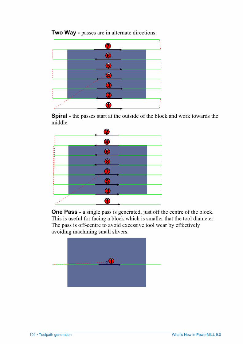
104 • Toolpath generation What's New in PowerMILL 9.0
Two Way - passes are in alternate directions.
Spiral - the passes start at the outside of the block and work towards the middle.
One Pass - a single pass is generated, just off the centre of the block. This is useful for facing a block which is smaller that the tool diameter. The pass is off-centre to avoid excessive tool wear by effectively avoiding machining small slivers.
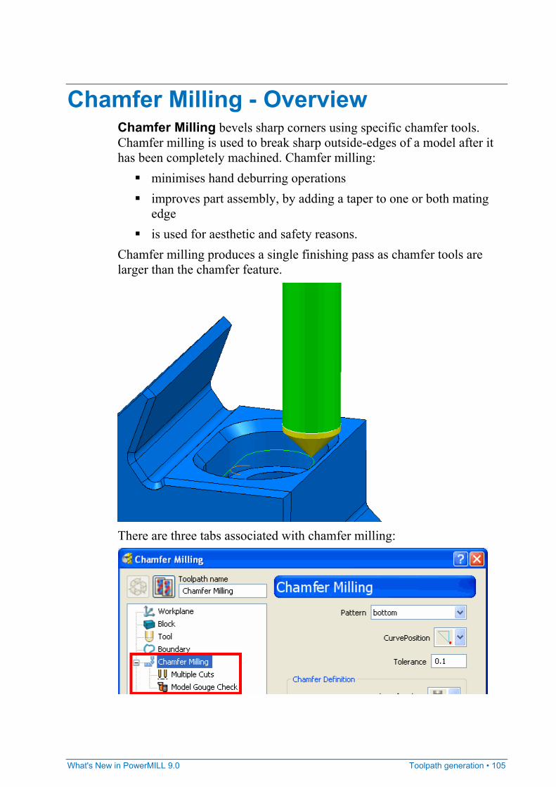
What's New in PowerMILL 9.0 Toolpath generation • 105
Chamfer Milling - Overview Chamfer Milling bevels sharp corners using specific chamfer tools. Chamfer milling is used to break sharp outside-edges of a model after it has been completely machined. Chamfer milling:
minimises hand deburring operations improves part assembly, by adding a taper to one or both mating
edge is used for aesthetic and safety reasons.
Chamfer milling produces a single finishing pass as chamfer tools are larger than the chamfer feature.
There are three tabs associated with chamfer milling:
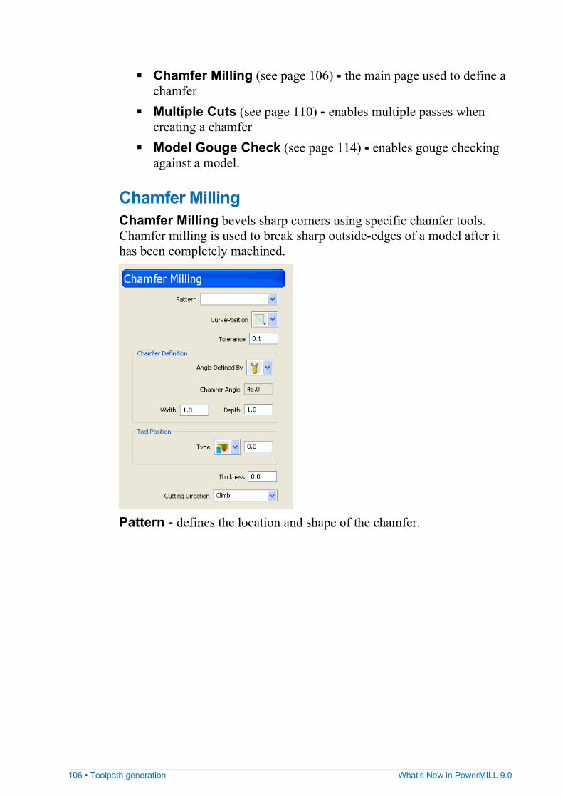
106 • Toolpath generation What's New in PowerMILL 9.0
Chamfer Milling (see page 106) - the main page used to define a chamfer
Multiple Cuts (see page 110) - enables multiple passes when creating a chamfer
Model Gouge Check (see page 114) - enables gouge checking against a model.
Chamfer Milling Chamfer Milling bevels sharp corners using specific chamfer tools. Chamfer milling is used to break sharp outside-edges of a model after it has been completely machined.
Pattern - defines the location and shape of the chamfer.
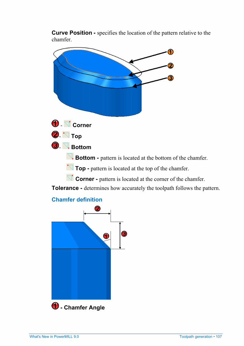
What's New in PowerMILL 9.0 Toolpath generation • 107
Curve Position - specifies the location of the pattern relative to the chamfer.
- Corner
- Top
- Bottom
Bottom - pattern is located at the bottom of the chamfer.
Top - pattern is located at the top of the chamfer.
Corner - pattern is located at the corner of the chamfer. Tolerance - determines how accurately the toolpath follows the pattern.
Chamfer definition
- Chamfer Angle
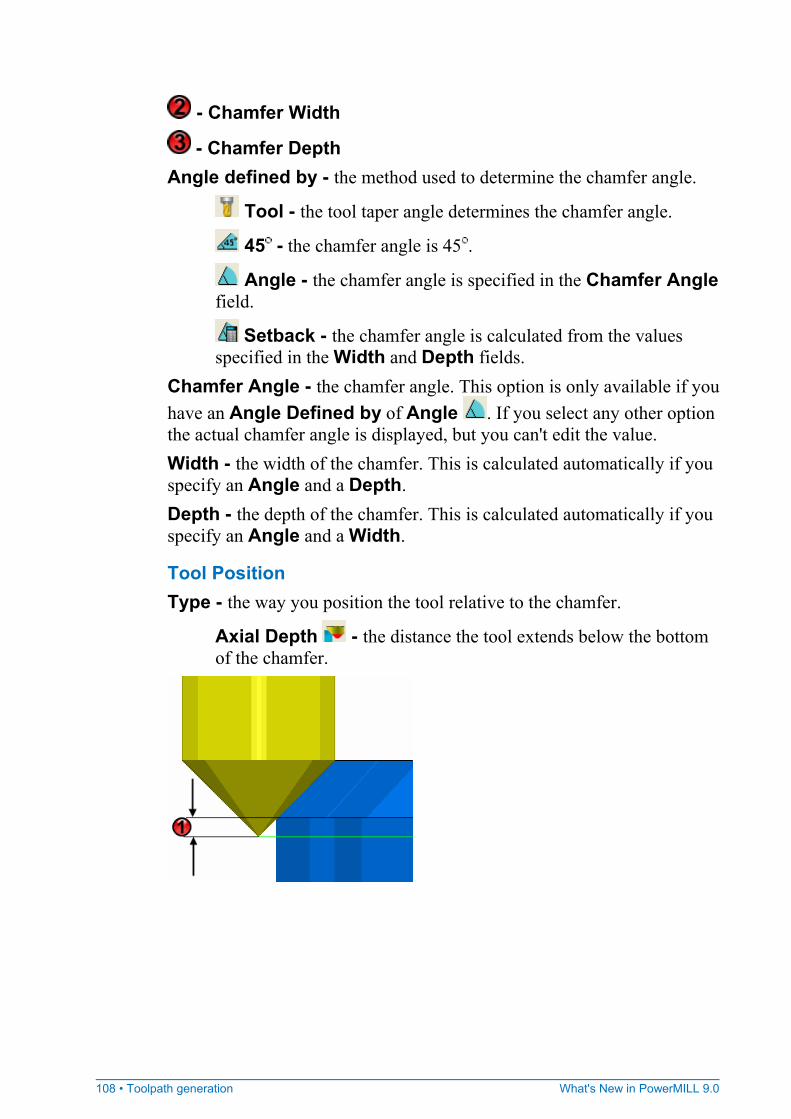
108 • Toolpath generation What's New in PowerMILL 9.0
- Chamfer Width
- Chamfer Depth Angle defined by - the method used to determine the chamfer angle.
Tool - the tool taper angle determines the chamfer angle.
45 - the chamfer angle is 45 .
Angle - the chamfer angle is specified in the Chamfer Angle field.
Setback - the chamfer angle is calculated from the values specified in the Width and Depth fields.
Chamfer Angle - the chamfer angle. This option is only available if you have an Angle Defined by of Angle . If you select any other option the actual chamfer angle is displayed, but you can't edit the value. Width - the width of the chamfer. This is calculated automatically if you specify an Angle and a Depth. Depth - the depth of the chamfer. This is calculated automatically if you specify an Angle and a Width.
Tool Position Type - the way you position the tool relative to the chamfer.
Axial Depth - the distance the tool extends below the bottom of the chamfer.
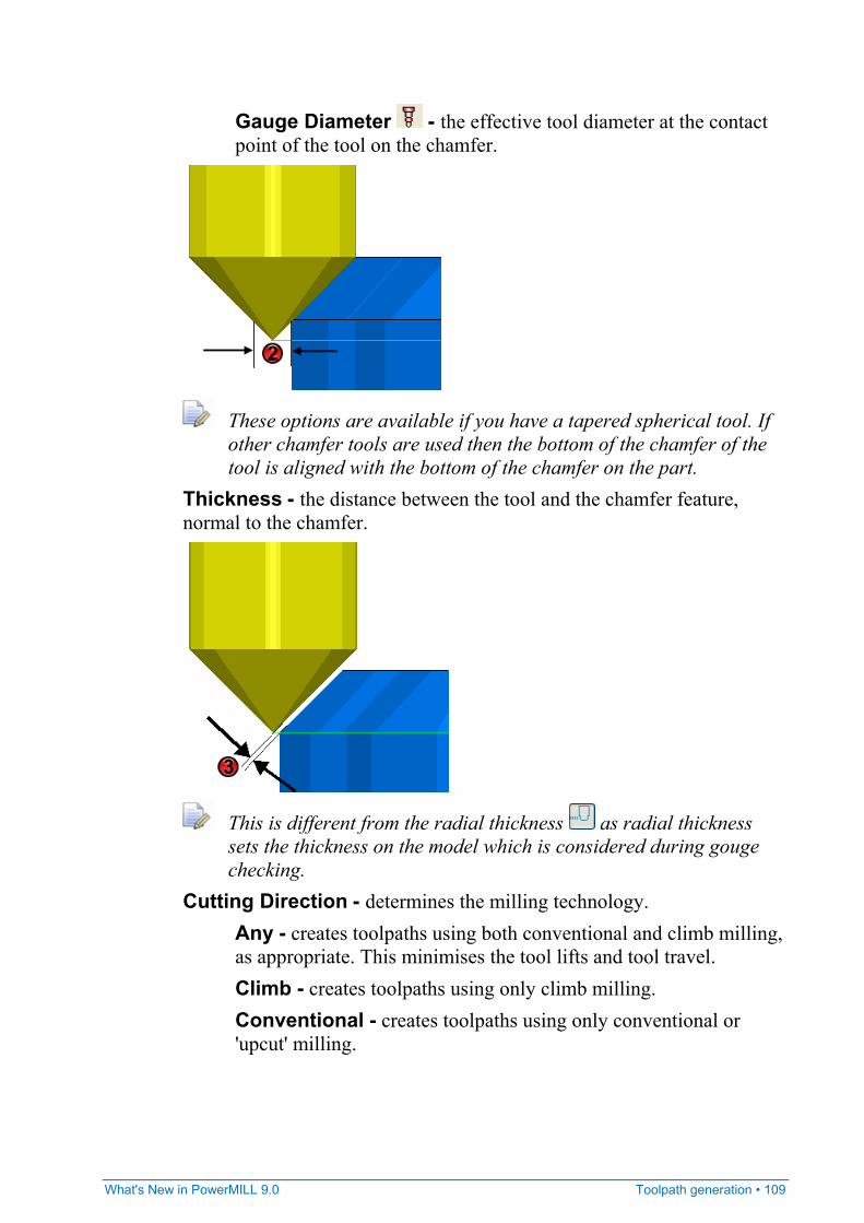
What's New in PowerMILL 9.0 Toolpath generation • 109
Gauge Diameter - the effective tool diameter at the contact point of the tool on the chamfer.
These options are available if you have a tapered spherical tool. If other chamfer tools are used then the bottom of the chamfer of the tool is aligned with the bottom of the chamfer on the part.
Thickness - the distance between the tool and the chamfer feature, normal to the chamfer.
This is different from the radial thickness as radial thickness sets the thickness on the model which is considered during gouge checking.
Cutting Direction - determines the milling technology. Any - creates toolpaths using both conventional and climb milling, as appropriate. This minimises the tool lifts and tool travel. Climb - creates toolpaths using only climb milling. Conventional - creates toolpaths using only conventional or 'upcut' milling.
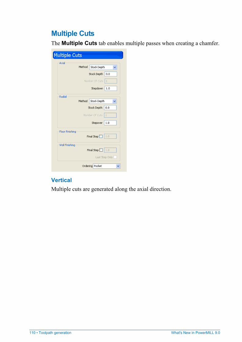
110 • Toolpath generation What's New in PowerMILL 9.0
Multiple Cuts The Multiple Cuts tab enables multiple passes when creating a chamfer.
Vertical Multiple cuts are generated along the axial direction.
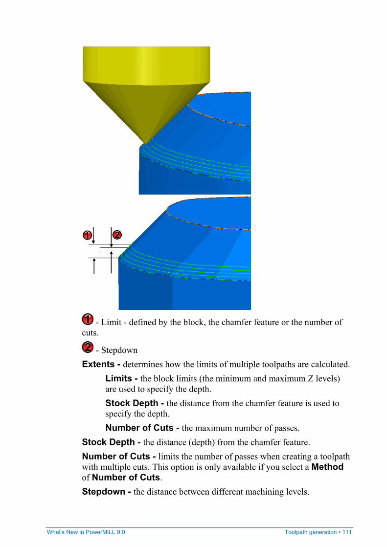
What's New in PowerMILL 9.0 Toolpath generation • 111
- Limit - defined by the block, the chamfer feature or the number of cuts.
- Stepdown Extents - determines how the limits of multiple toolpaths are calculated.
Limits - the block limits (the minimum and maximum Z levels) are used to specify the depth. Stock Depth - the distance from the chamfer feature is used to specify the depth. Number of Cuts - the maximum number of passes.
Stock Depth - the distance (depth) from the chamfer feature. Number of Cuts - limits the number of passes when creating a toolpath with multiple cuts. This option is only available if you select a Method of Number of Cuts. Stepdown - the distance between different machining levels.
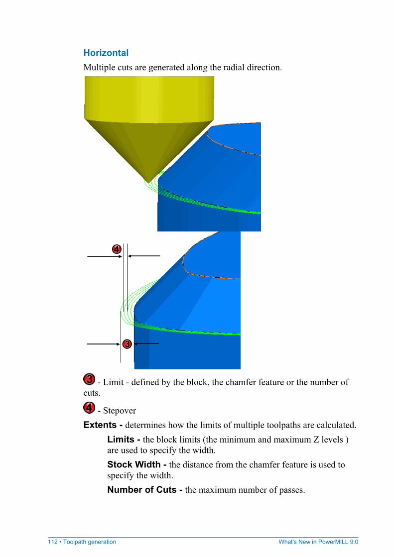
112 • Toolpath generation What's New in PowerMILL 9.0
Horizontal Multiple cuts are generated along the radial direction.
- Limit - defined by the block, the chamfer feature or the number of cuts.
- Stepover Extents - determines how the limits of multiple toolpaths are calculated.
Limits - the block limits (the minimum and maximum Z levels ) are used to specify the width. Stock Width - the distance from the chamfer feature is used to specify the width. Number of Cuts - the maximum number of passes.
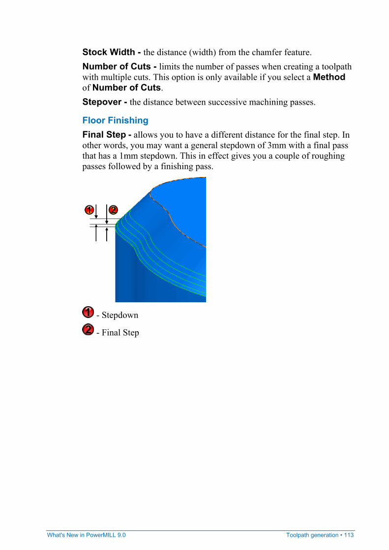
What's New in PowerMILL 9.0 Toolpath generation • 113
Stock Width - the distance (width) from the chamfer feature. Number of Cuts - limits the number of passes when creating a toolpath with multiple cuts. This option is only available if you select a Method of Number of Cuts. Stepover - the distance between successive machining passes.
Floor Finishing Final Step - allows you to have a different distance for the final step. In other words, you may want a general stepdown of 3mm with a final pass that has a 1mm stepdown. This in effect gives you a couple of roughing passes followed by a finishing pass.
- Stepdown
- Final Step
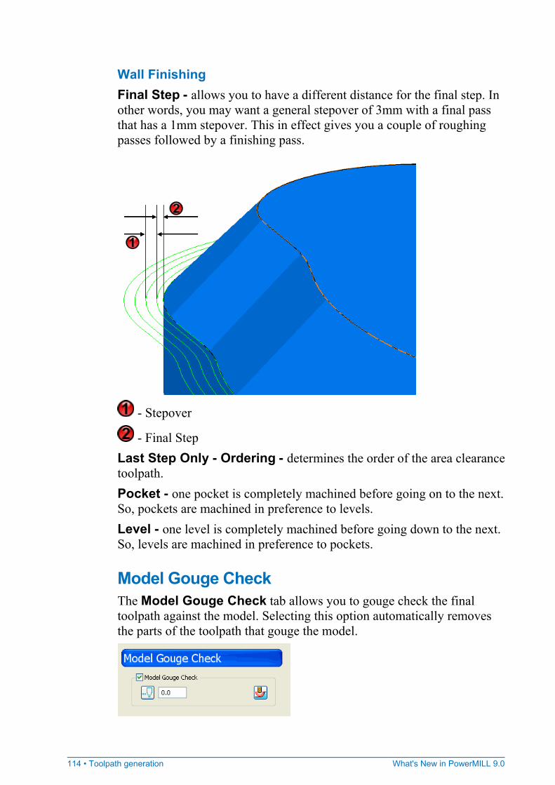
114 • Toolpath generation What's New in PowerMILL 9.0
Wall Finishing Final Step - allows you to have a different distance for the final step. In other words, you may want a general stepover of 3mm with a final pass that has a 1mm stepover. This in effect gives you a couple of roughing passes followed by a finishing pass.
- Stepover
- Final Step Last Step Only - Ordering - determines the order of the area clearance toolpath. Pocket - one pocket is completely machined before going on to the next. So, pockets are machined in preference to levels. Level - one level is completely machined before going down to the next. So, levels are machined in preference to pockets.
Model Gouge Check The Model Gouge Check tab allows you to gouge check the final toolpath against the model. Selecting this option automatically removes the parts of the toolpath that gouge the model.

What's New in PowerMILL 9.0 Toolpath generation • 115
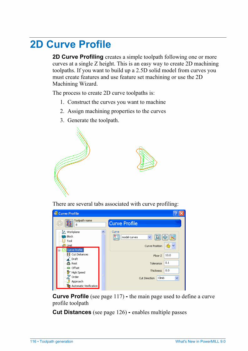
116 • Toolpath generation What's New in PowerMILL 9.0
2D Curve Profile 2D Curve Profiling creates a simple toolpath following one or more curves at a single Z height. This is an easy way to create 2D machining toolpaths. If you want to build up a 2.5D solid model from curves you must create features and use feature set machining or use the 2D Machining Wizard. The process to create 2D curve toolpaths is:
1. Construct the curves you want to machine 2. Assign machining properties to the curves 3. Generate the toolpath.
There are several tabs associated with curve profiling:
Curve Profile (see page 117) - the main page used to define a curve profile toolpath Cut Distances (see page 126) - enables multiple passes
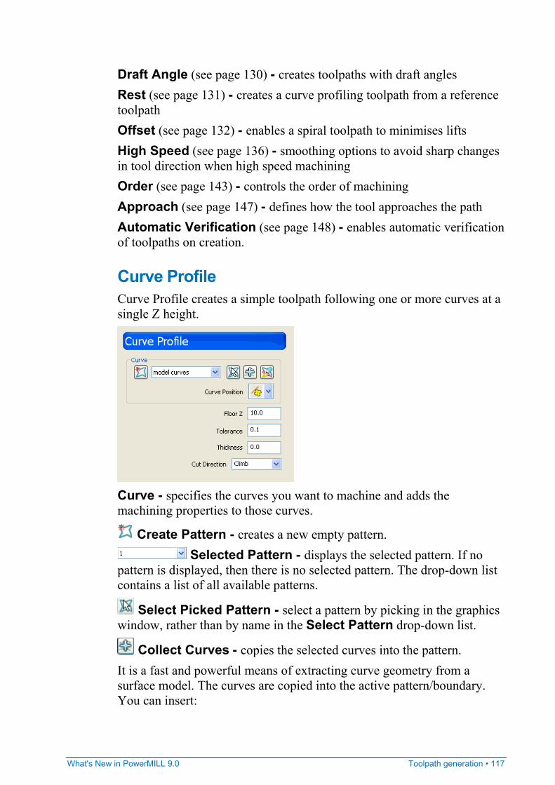
What's New in PowerMILL 9.0 Toolpath generation • 117
Draft Angle (see page 130) - creates toolpaths with draft angles Rest (see page 131) - creates a curve profiling toolpath from a reference toolpath Offset (see page 132) - enables a spiral toolpath to minimises lifts High Speed (see page 136) - smoothing options to avoid sharp changes in tool direction when high speed machining Order (see page 143) - controls the order of machining Approach (see page 147) - defines how the tool approaches the path Automatic Verification (see page 148) - enables automatic verification of toolpaths on creation.
Curve Profile Curve Profile creates a simple toolpath following one or more curves at a single Z height.
Curve - specifies the curves you want to machine and adds the machining properties to those curves.
Create Pattern - creates a new empty pattern. Selected Pattern - displays the selected pattern. If no
pattern is displayed, then there is no selected pattern. The drop-down list contains a list of all available patterns.
Select Picked Pattern - select a pattern by picking in the graphics window, rather than by name in the Select Pattern drop-down list.
Collect Curves - copies the selected curves into the pattern. It is a fast and powerful means of extracting curve geometry from a surface model. The curves are copied into the active pattern/boundary. You can insert:
118 • Toolpath generation What's New in PowerMILL 9.0
Individual surface boundary curves. Boundary curves around a selection of surfaces. Model wireframe geometry. Existing pattern or boundary segments.
If internal profiles exist, they are NOT generated. For more information see the Collecting curves example (see page 10).
Edit Machining Sections (see page 118) - specifies: which regions of the curve are machined which side of the curve is machined the machining strategy.
Curve Position - determines which part of the tool follows the curve.
Centre Position - the centre of the tool follows the curve.
Contact Position - the contact point of the tool follows the curve. Floor Z (see page 123) - the machining height. Tolerance - determines how accurately the toolpath follows the curve. Curve Thickness (see page 125) - an offset of the curve by the amount specified. This is a curve, not a model thickness. Cut Direction - determines the milling technology.
Any - creates toolpaths using both conventional and climb milling, as appropriate. This minimises the tool lifts and tool travel. Climb - creates toolpaths using only climb milling. Conventional - creates toolpaths using only conventional or 'upcut' milling.
Edit Machining Sections The Edit Machining Sections specifies:
which regions of the curve are machined which side of the curve is machined the machining strategy.
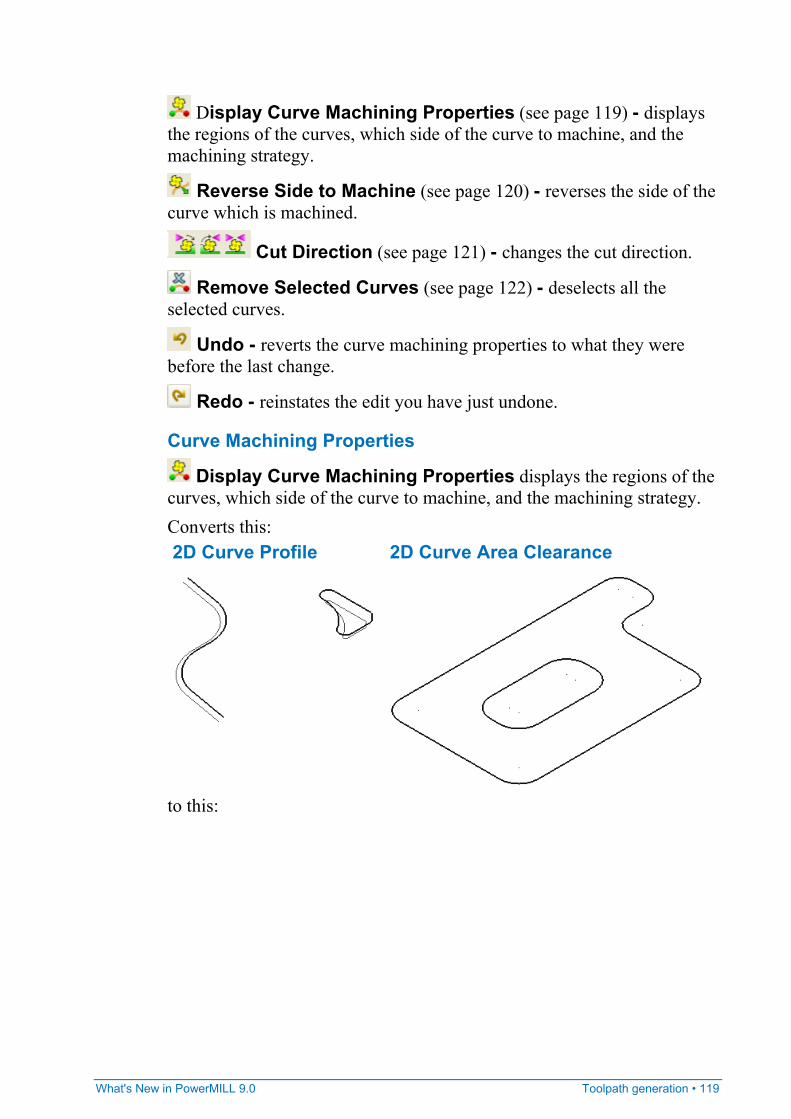
What's New in PowerMILL 9.0 Toolpath generation • 119
Display Curve Machining Properties (see page 119) - displays the regions of the curves, which side of the curve to machine, and the machining strategy.
Reverse Side to Machine (see page 120) - reverses the side of the curve which is machined.
Cut Direction (see page 121) - changes the cut direction.
Remove Selected Curves (see page 122) - deselects all the selected curves.
Undo - reverts the curve machining properties to what they were before the last change.
Redo - reinstates the edit you have just undone.
Curve Machining Properties
Display Curve Machining Properties displays the regions of the curves, which side of the curve to machine, and the machining strategy. Converts this: 2D Curve Profile 2D Curve Area Clearance
to this:
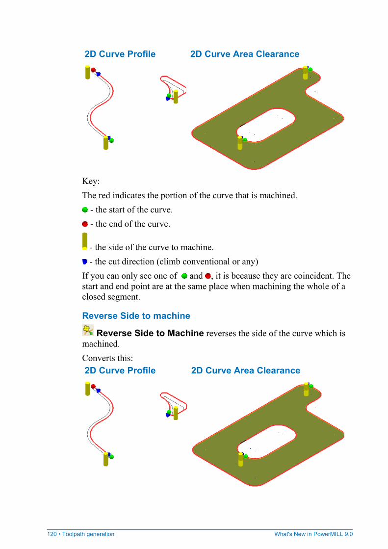
120 • Toolpath generation What's New in PowerMILL 9.0
2D Curve Profile 2D Curve Area Clearance
Key: The red indicates the portion of the curve that is machined.
- the start of the curve. - the end of the curve.
- the side of the curve to machine. - the cut direction (climb conventional or any)
If you can only see one of and , it is because they are coincident. The start and end point are at the same place when machining the whole of a closed segment.
Reverse Side to machine
Reverse Side to Machine reverses the side of the curve which is machined. Converts this: 2D Curve Profile 2D Curve Area Clearance
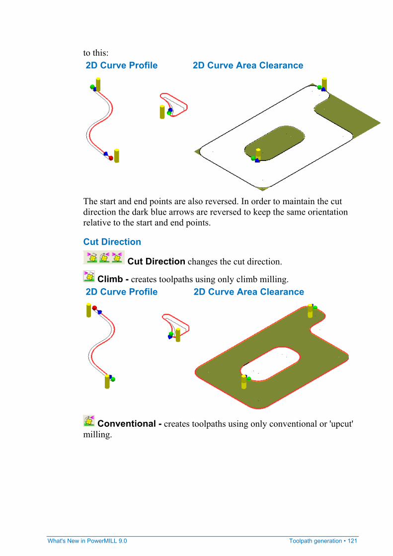
What's New in PowerMILL 9.0 Toolpath generation • 121
to this: 2D Curve Profile 2D Curve Area Clearance
The start and end points are also reversed. In order to maintain the cut direction the dark blue arrows are reversed to keep the same orientation relative to the start and end points.
Cut Direction
Cut Direction changes the cut direction.
Climb - creates toolpaths using only climb milling. 2D Curve Profile 2D Curve Area Clearance
Conventional - creates toolpaths using only conventional or 'upcut' milling.
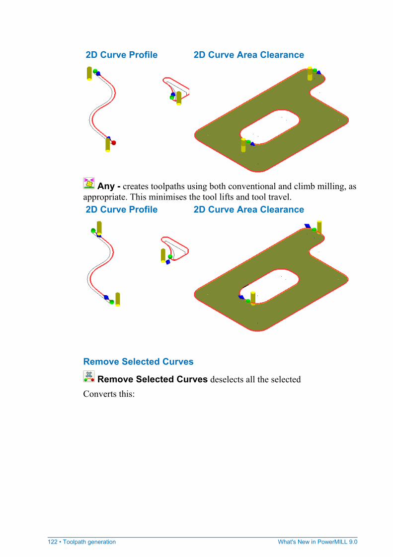
122 • Toolpath generation What's New in PowerMILL 9.0
2D Curve Profile 2D Curve Area Clearance
Any - creates toolpaths using both conventional and climb milling, as appropriate. This minimises the tool lifts and tool travel. 2D Curve Profile 2D Curve Area Clearance
Remove Selected Curves
Remove Selected Curves deselects all the selected Converts this:
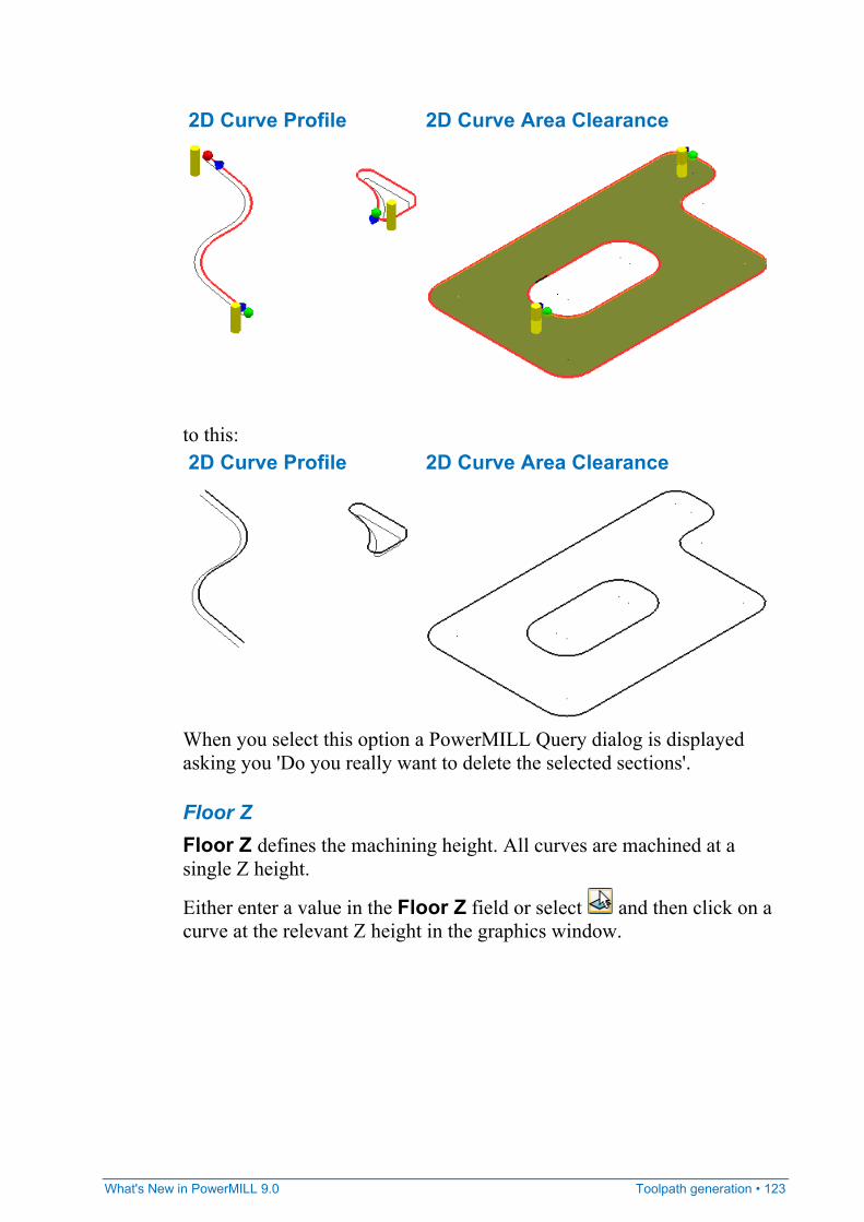
What's New in PowerMILL 9.0 Toolpath generation • 123
2D Curve Profile 2D Curve Area Clearance
to this: 2D Curve Profile 2D Curve Area Clearance
When you select this option a PowerMILL Query dialog is displayed asking you 'Do you really want to delete the selected sections'.
Floor Z Floor Z defines the machining height. All curves are machined at a single Z height.
Either enter a value in the Floor Z field or select and then click on a curve at the relevant Z height in the graphics window.
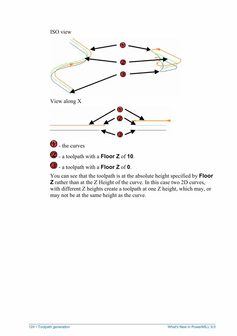
124 • Toolpath generation What's New in PowerMILL 9.0
ISO view
View along X
- the curves
- a toolpath with a Floor Z of 10.
- a toolpath with a Floor Z of 0. You can see that the toolpath is at the absolute height specified by Floor Z rather than at the Z Height of the curve. In this case two 2D curves, with different Z heights create a toolpath at one Z height, which may, or may not be at the same height as the curve.
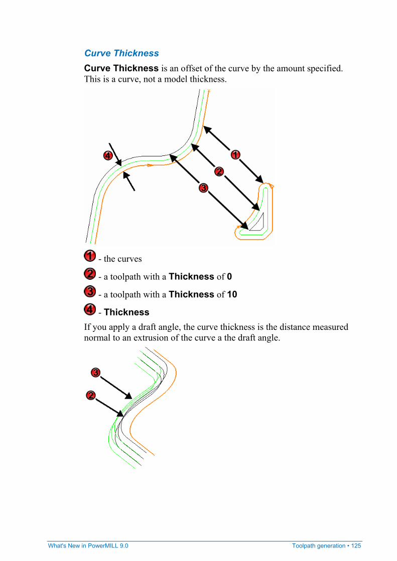
What's New in PowerMILL 9.0 Toolpath generation • 125
Curve Thickness Curve Thickness is an offset of the curve by the amount specified. This is a curve, not a model thickness.
- the curves
- a toolpath with a Thickness of 0
- a toolpath with a Thickness of 10
- Thickness If you apply a draft angle, the curve thickness is the distance measured normal to an extrusion of the curve a the draft angle.
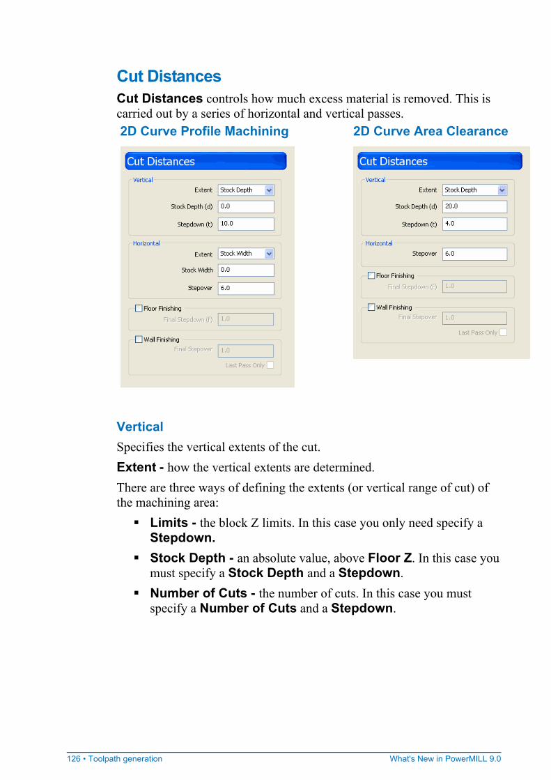
126 • Toolpath generation What's New in PowerMILL 9.0
Cut Distances Cut Distances controls how much excess material is removed. This is carried out by a series of horizontal and vertical passes. 2D Curve Profile Machining 2D Curve Area Clearance
Vertical Specifies the vertical extents of the cut. Extent - how the vertical extents are determined. There are three ways of defining the extents (or vertical range of cut) of the machining area:
Limits - the block Z limits. In this case you only need specify a Stepdown.
Stock Depth - an absolute value, above Floor Z. In this case you must specify a Stock Depth and a Stepdown.
Number of Cuts - the number of cuts. In this case you must specify a Number of Cuts and a Stepdown.
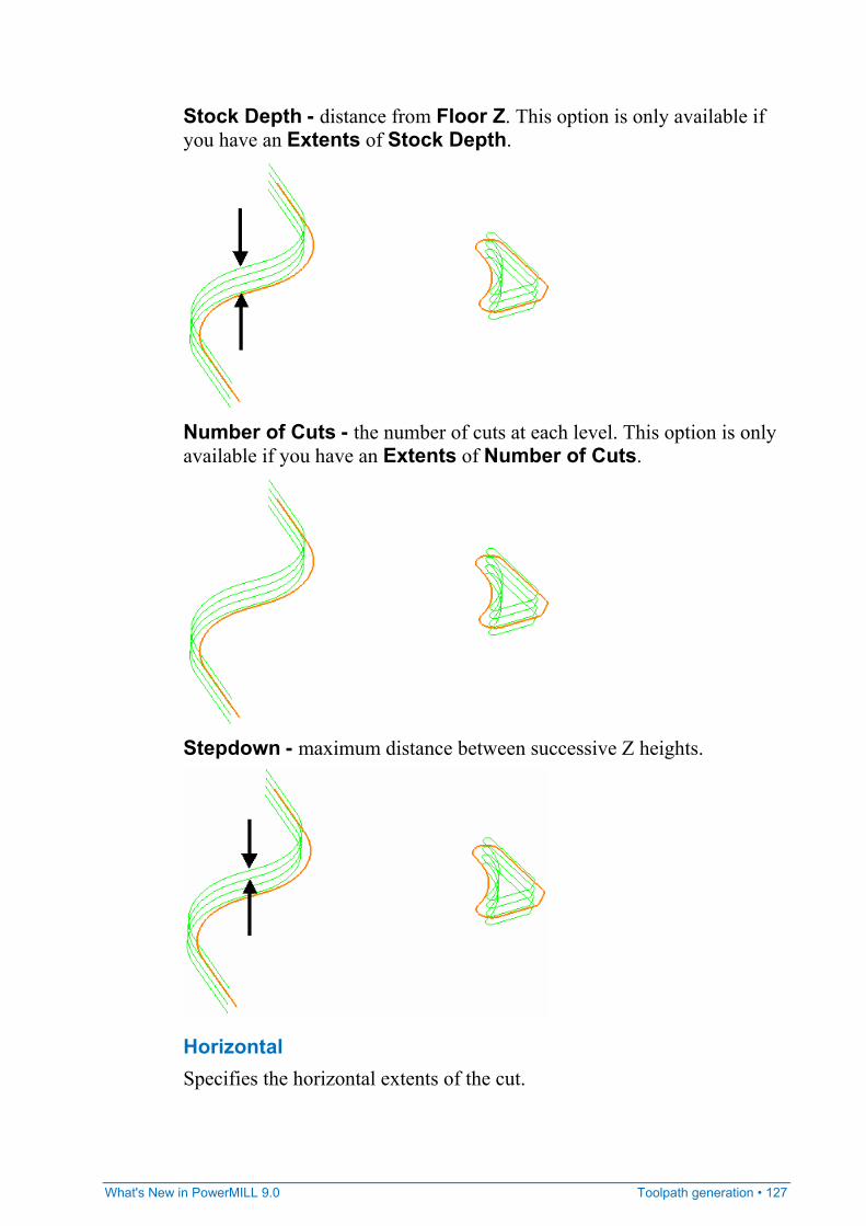
What's New in PowerMILL 9.0 Toolpath generation • 127
Stock Depth - distance from Floor Z. This option is only available if you have an Extents of Stock Depth.
Number of Cuts - the number of cuts at each level. This option is only available if you have an Extents of Number of Cuts.
Stepdown - maximum distance between successive Z heights.
Horizontal Specifies the horizontal extents of the cut.
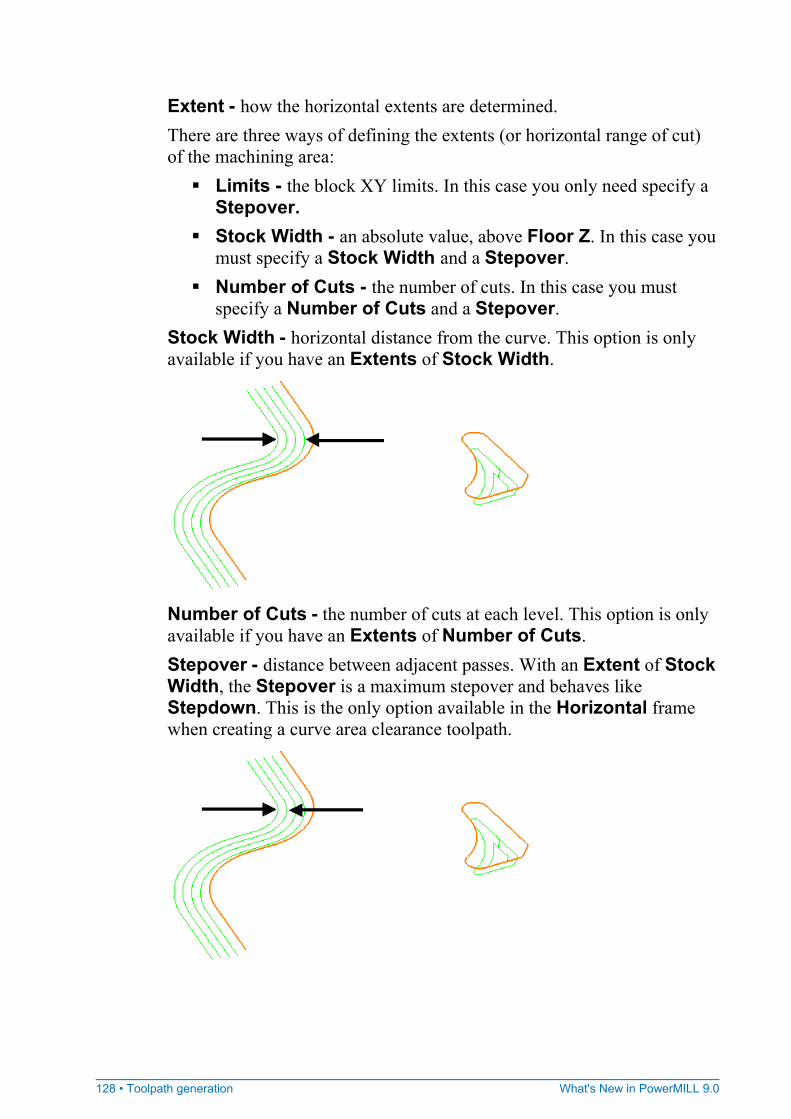
128 • Toolpath generation What's New in PowerMILL 9.0
Extent - how the horizontal extents are determined. There are three ways of defining the extents (or horizontal range of cut) of the machining area:
Limits - the block XY limits. In this case you only need specify a Stepover.
Stock Width - an absolute value, above Floor Z. In this case you must specify a Stock Width and a Stepover.
Number of Cuts - the number of cuts. In this case you must specify a Number of Cuts and a Stepover.
Stock Width - horizontal distance from the curve. This option is only available if you have an Extents of Stock Width.
Number of Cuts - the number of cuts at each level. This option is only available if you have an Extents of Number of Cuts. Stepover - distance between adjacent passes. With an Extent of Stock Width, the Stepover is a maximum stepover and behaves like Stepdown. This is the only option available in the Horizontal frame when creating a curve area clearance toolpath.
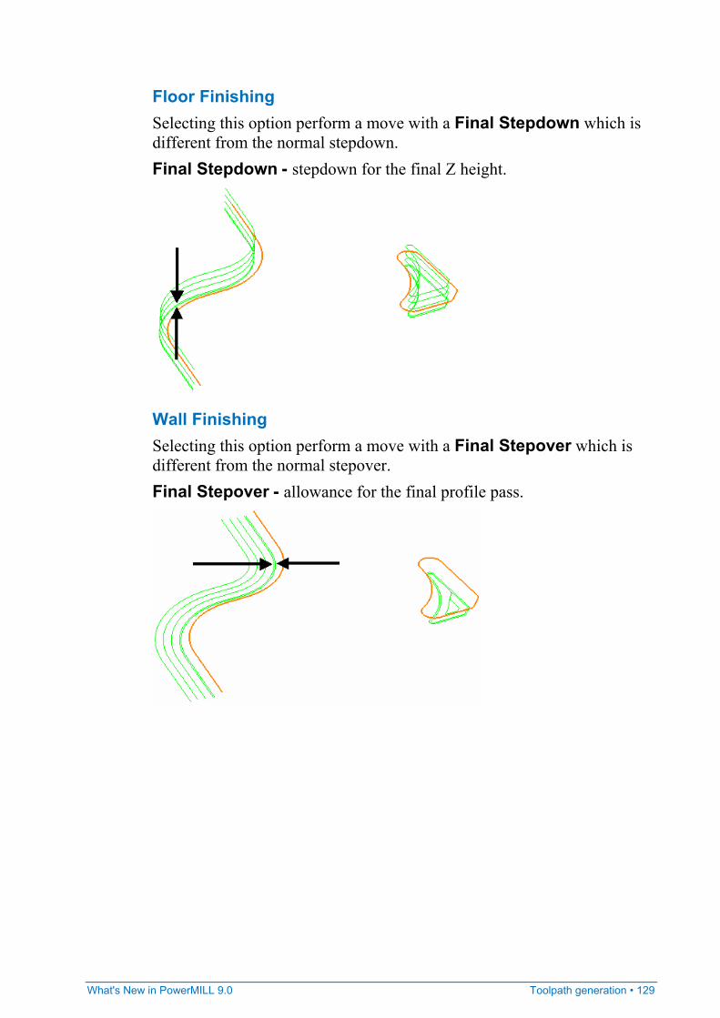
What's New in PowerMILL 9.0 Toolpath generation • 129
Floor Finishing Selecting this option perform a move with a Final Stepdown which is different from the normal stepdown. Final Stepdown - stepdown for the final Z height.
Wall Finishing Selecting this option perform a move with a Final Stepover which is different from the normal stepover. Final Stepover - allowance for the final profile pass.
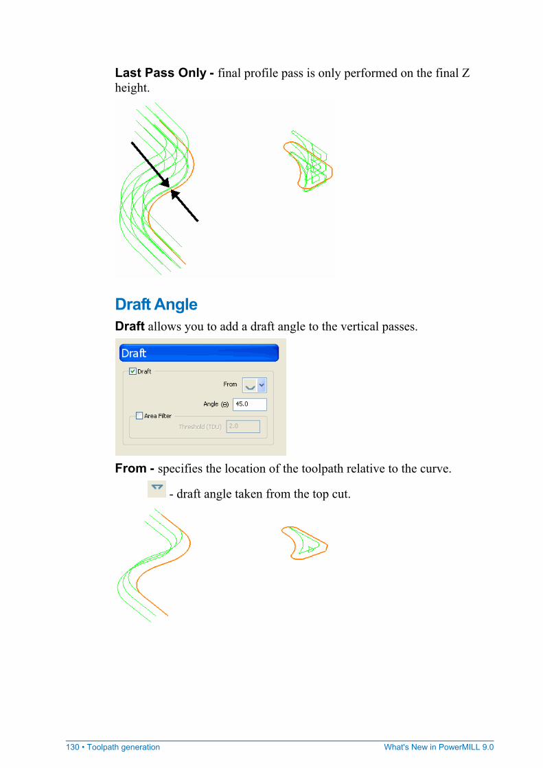
130 • Toolpath generation What's New in PowerMILL 9.0
Last Pass Only - final profile pass is only performed on the final Z height.
Draft Angle Draft allows you to add a draft angle to the vertical passes.
From - specifies the location of the toolpath relative to the curve.
- draft angle taken from the top cut.
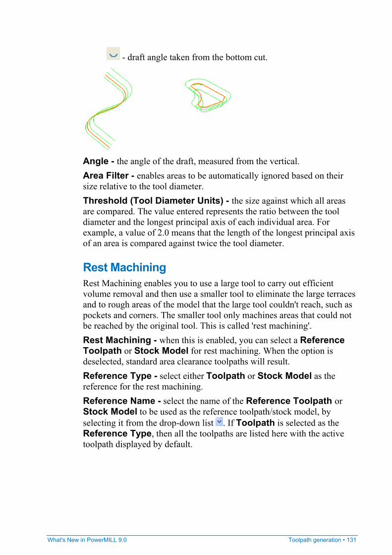
What's New in PowerMILL 9.0 Toolpath generation • 131
- draft angle taken from the bottom cut.
Angle - the angle of the draft, measured from the vertical. Area Filter - enables areas to be automatically ignored based on their size relative to the tool diameter. Threshold (Tool Diameter Units) - the size against which all areas are compared. The value entered represents the ratio between the tool diameter and the longest principal axis of each individual area. For example, a value of 2.0 means that the length of the longest principal axis of an area is compared against twice the tool diameter.
Rest Machining Rest Machining enables you to use a large tool to carry out efficient volume removal and then use a smaller tool to eliminate the large terraces and to rough areas of the model that the large tool couldn't reach, such as pockets and corners. The smaller tool only machines areas that could not be reached by the original tool. This is called 'rest machining'. Rest Machining - when this is enabled, you can select a Reference Toolpath or Stock Model for rest machining. When the option is deselected, standard area clearance toolpaths will result. Reference Type - select either Toolpath or Stock Model as the reference for the rest machining. Reference Name - select the name of the Reference Toolpath or Stock Model to be used as the reference toolpath/stock model, by selecting it from the drop-down list . If Toolpath is selected as the Reference Type, then all the toolpaths are listed here with the active toolpath displayed by default.
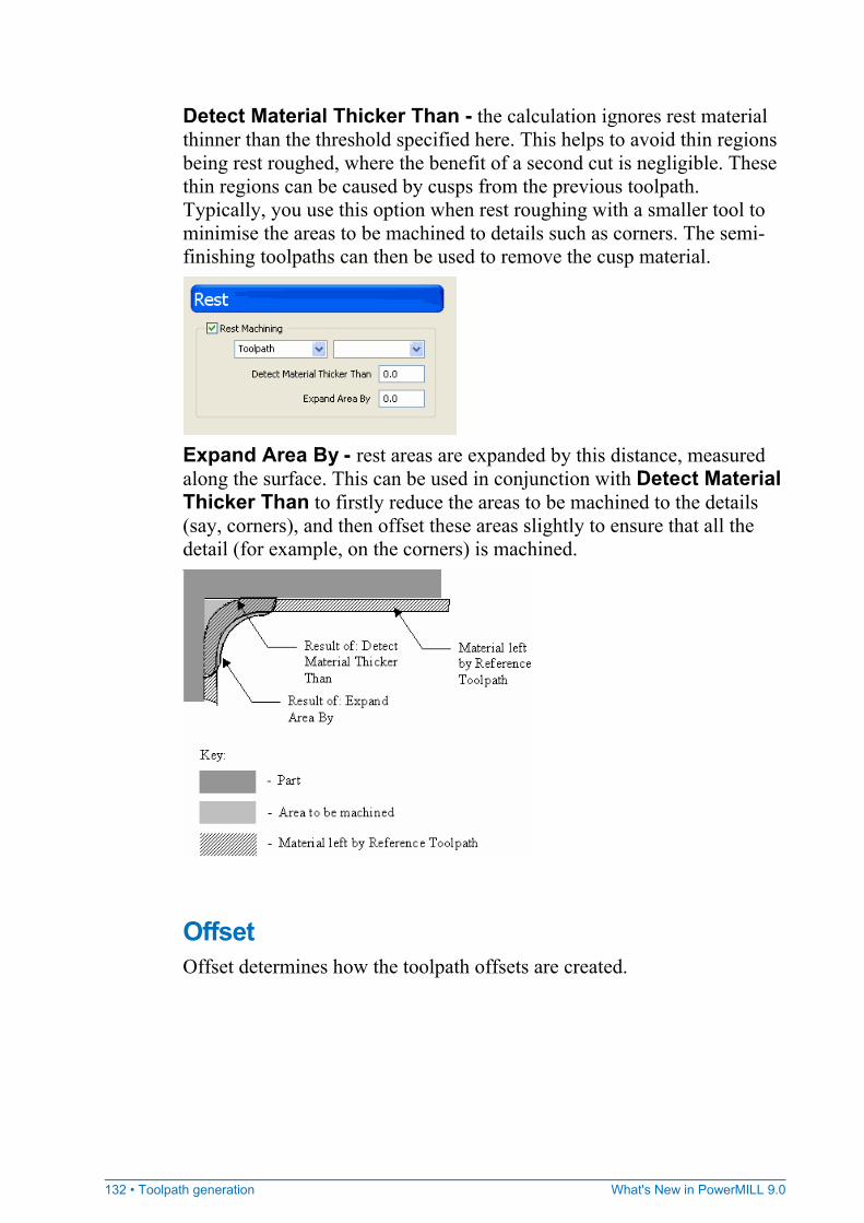
132 • Toolpath generation What's New in PowerMILL 9.0
Detect Material Thicker Than - the calculation ignores rest material thinner than the threshold specified here. This helps to avoid thin regions being rest roughed, where the benefit of a second cut is negligible. These thin regions can be caused by cusps from the previous toolpath. Typically, you use this option when rest roughing with a smaller tool to minimise the areas to be machined to details such as corners. The semi-finishing toolpaths can then be used to remove the cusp material.
Expand Area By - rest areas are expanded by this distance, measured along the surface. This can be used in conjunction with Detect Material Thicker Than to firstly reduce the areas to be machined to the details (say, corners), and then offset these areas slightly to ensure that all the detail (for example, on the corners) is machined.
Offset Offset determines how the toolpath offsets are created.
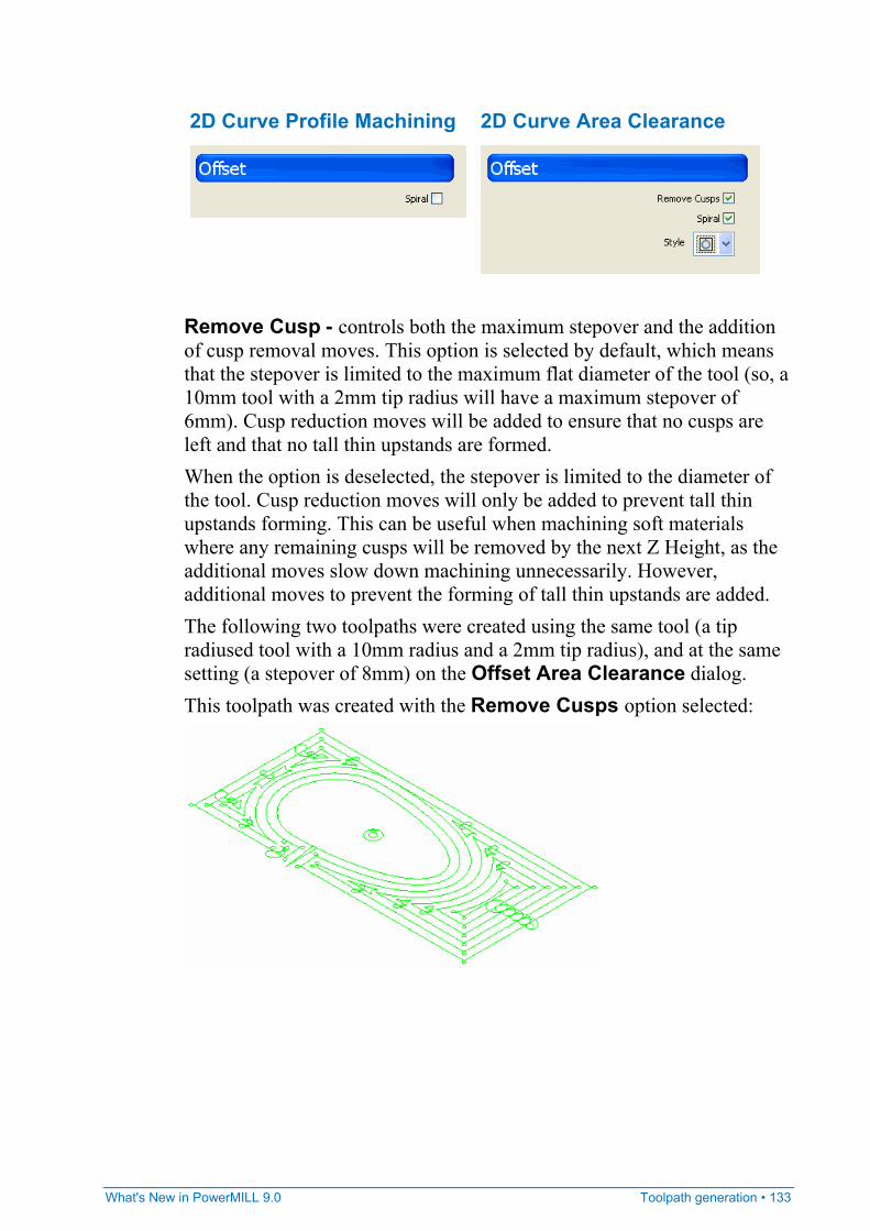
What's New in PowerMILL 9.0 Toolpath generation • 133
2D Curve Profile Machining 2D Curve Area Clearance
Remove Cusp - controls both the maximum stepover and the addition of cusp removal moves. This option is selected by default, which means that the stepover is limited to the maximum flat diameter of the tool (so, a 10mm tool with a 2mm tip radius will have a maximum stepover of 6mm). Cusp reduction moves will be added to ensure that no cusps are left and that no tall thin upstands are formed. When the option is deselected, the stepover is limited to the diameter of the tool. Cusp reduction moves will only be added to prevent tall thin upstands forming. This can be useful when machining soft materials where any remaining cusps will be removed by the next Z Height, as the additional moves slow down machining unnecessarily. However, additional moves to prevent the forming of tall thin upstands are added. The following two toolpaths were created using the same tool (a tip radiused tool with a 10mm radius and a 2mm tip radius), and at the same setting (a stepover of 8mm) on the Offset Area Clearance dialog. This toolpath was created with the Remove Cusps option selected:
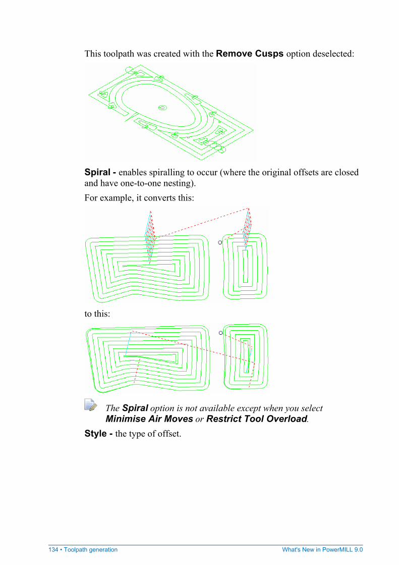
134 • Toolpath generation What's New in PowerMILL 9.0
This toolpath was created with the Remove Cusps option deselected:
Spiral - enables spiralling to occur (where the original offsets are closed and have one-to-one nesting). For example, it converts this:
to this:
The Spiral option is not available except when you select Minimise Air Moves or Restrict Tool Overload.
Style - the type of offset.
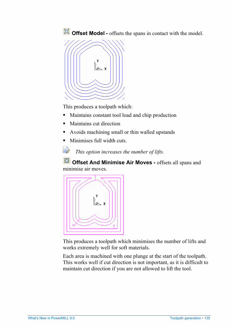
What's New in PowerMILL 9.0 Toolpath generation • 135
Offset Model - offsets the spans in contact with the model.
This produces a toolpath which: Maintains constant tool load and chip production Maintains cut direction Avoids machining small or thin walled upstands Minimises full width cuts.
This option increases the number of lifts.
Offset And Minimise Air Moves - offsets all spans and minimise air moves.
This produces a toolpath which minimises the number of lifts and works extremely well for soft materials. Each area is machined with one plunge at the start of the toolpath. This works well if cut direction is not important, as it is difficult to maintain cut direction if you are not allowed to lift the tool.
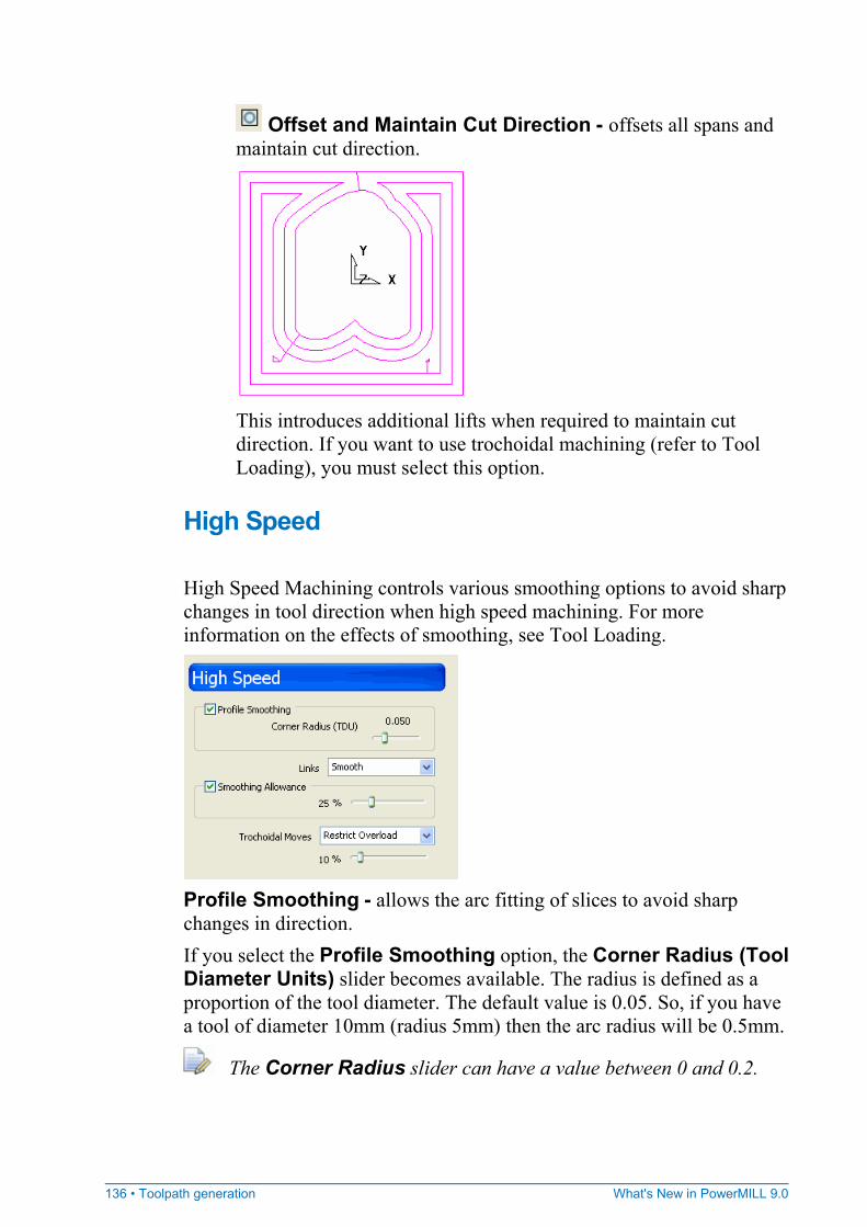
136 • Toolpath generation What's New in PowerMILL 9.0
Offset and Maintain Cut Direction - offsets all spans and maintain cut direction.
This introduces additional lifts when required to maintain cut direction. If you want to use trochoidal machining (refer to Tool Loading), you must select this option.
High Speed High Speed Machining controls various smoothing options to avoid sharp changes in tool direction when high speed machining. For more information on the effects of smoothing, see Tool Loading.
Profile Smoothing - allows the arc fitting of slices to avoid sharp changes in direction. If you select the Profile Smoothing option, the Corner Radius (Tool Diameter Units) slider becomes available. The radius is defined as a proportion of the tool diameter. The default value is 0.05. So, if you have a tool of diameter 10mm (radius 5mm) then the arc radius will be 0.5mm.
The Corner Radius slider can have a value between 0 and 0.2.
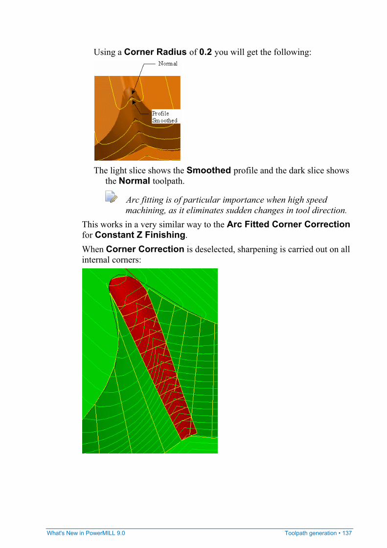
What's New in PowerMILL 9.0 Toolpath generation • 137
Using a Corner Radius of 0.2 you will get the following:
The light slice shows the Smoothed profile and the dark slice shows
the Normal toolpath.
Arc fitting is of particular importance when high speed machining, as it eliminates sudden changes in tool direction.
This works in a very similar way to the Arc Fitted Corner Correction for Constant Z Finishing. When Corner Correction is deselected, sharpening is carried out on all internal corners:
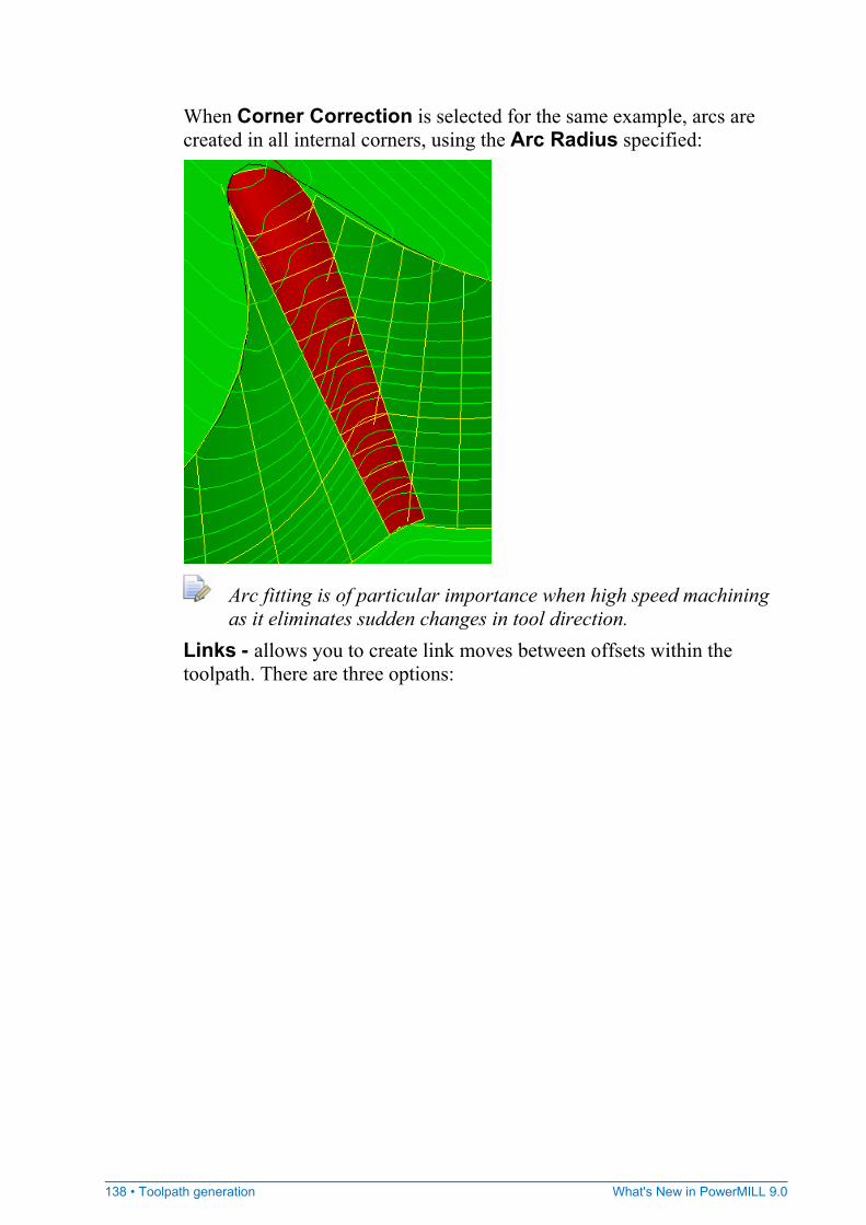
138 • Toolpath generation What's New in PowerMILL 9.0
When Corner Correction is selected for the same example, arcs are created in all internal corners, using the Arc Radius specified:
Arc fitting is of particular importance when high speed machining as it eliminates sudden changes in tool direction.
Links - allows you to create link moves between offsets within the toolpath. There are three options:
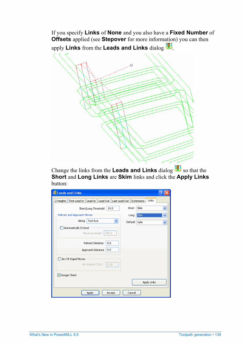
What's New in PowerMILL 9.0 Toolpath generation • 139
If you specify Links of None and you also have a Fixed Number of Offsets applied (see Stepover for more information) you can then apply Links from the Leads and Links dialog .
Change the links from the Leads and Links dialog so that the Short and Long Links are Skim links and click the Apply Links button:
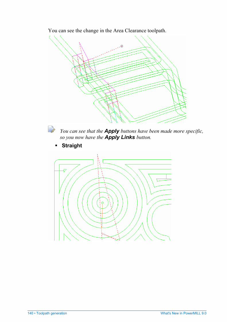
140 • Toolpath generation What's New in PowerMILL 9.0
You can see the change in the Area Clearance toolpath.
You can see that the Apply buttons have been made more specific, so you now have the Apply Links button.
Straight

What's New in PowerMILL 9.0 Toolpath generation • 141
Smooth
None
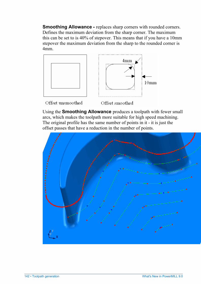
142 • Toolpath generation What's New in PowerMILL 9.0
Smoothing Allowance - replaces sharp corners with rounded corners. Defines the maximum deviation from the sharp corner. The maximum this can be set to is 40% of stepover. This means that if you have a 10mm stepover the maximum deviation from the sharp to the rounded corner is 4mm.
Using the Smoothing Allowance produces a toolpath with fewer small arcs, which makes the toolpath more suitable for high speed machining. The original profile has the same number of points in it - it is just the offset passes that have a reduction in the number of points.

What's New in PowerMILL 9.0 Toolpath generation • 143
Trochoidal Moves - controls the creation of trochoidal moves to minimise tool overload. For more information on the effects of trochoidal moves see Tool Loading. None - no trochoidal moves are created. Full - trochoidal moves are created all along the toolpath. Restrict Overload - as the tool approaches overload, PowerMILL automatically puts in a trochoidal path to remove the overload. This happens in corners, narrow channels, slots, and the first cut of an offset toolpath (which is, in effect, a narrow channel). Since some tool overload may be acceptable, it can be controlled by the slider. The default setting for the allowable overload is 10% of existing stepover. So, if you use a stepover of 10 and an allowable overload of 10%, trochoidal moves will not start appearing until an overload condition of 10% is exceeded.
When creating a Curve Profile toolpath, the Trochoidal Moves option is only available when using Multiple Cuts (set on the Cut Distance page).
When creating a Curve Area Clearance toolpath,The Trochoidal Moves option is only available when using a Type of Offset (set on the Curve Area Clearance page).
Order Order controls the order of machining.
Order by - determines the order of the area clearance toolpath. Region - one pocket is completely machined before going on to the next. So, pockets are machined in preference to levels. Level - one level is completely machined before going down to the next. So, levels are machined in preference to pockets.
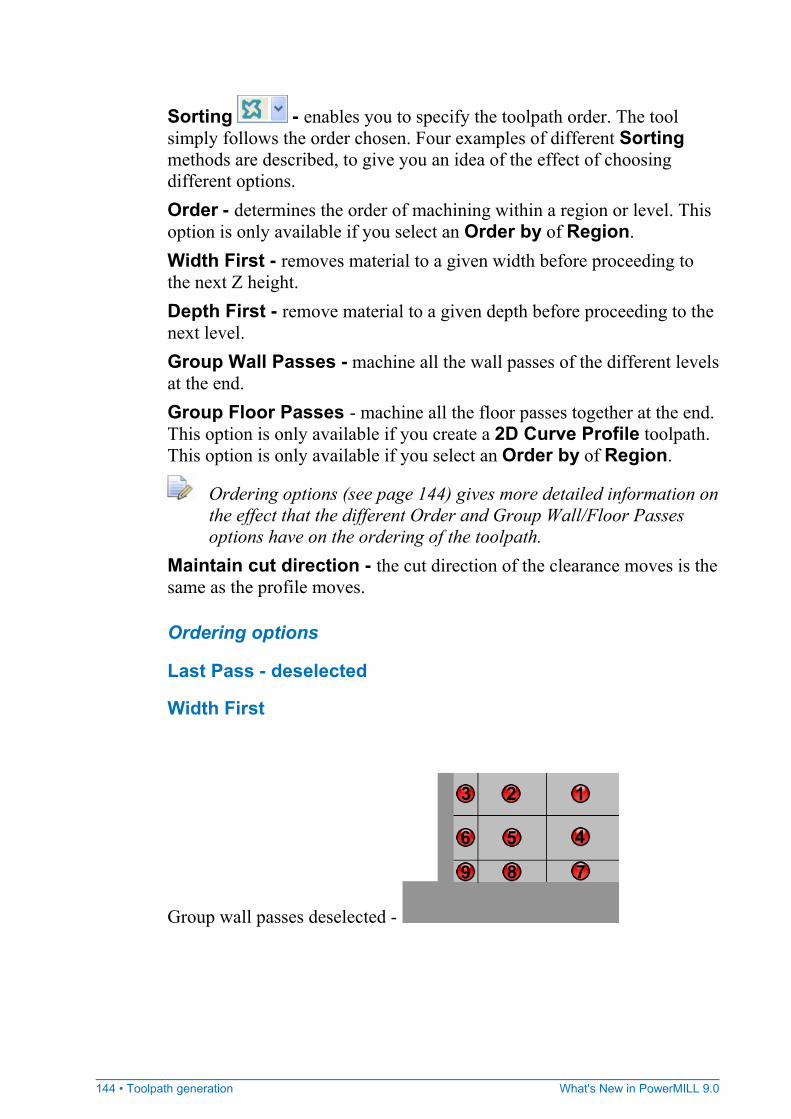
144 • Toolpath generation What's New in PowerMILL 9.0
Sorting - enables you to specify the toolpath order. The tool simply follows the order chosen. Four examples of different Sorting methods are described, to give you an idea of the effect of choosing different options. Order - determines the order of machining within a region or level. This option is only available if you select an Order by of Region. Width First - removes material to a given width before proceeding to the next Z height. Depth First - remove material to a given depth before proceeding to the next level. Group Wall Passes - machine all the wall passes of the different levels at the end. Group Floor Passes - machine all the floor passes together at the end. This option is only available if you create a 2D Curve Profile toolpath. This option is only available if you select an Order by of Region.
Ordering options (see page 144) gives more detailed information on the effect that the different Order and Group Wall/Floor Passes options have on the ordering of the toolpath.
Maintain cut direction - the cut direction of the clearance moves is the same as the profile moves.
Ordering options
Last Pass - deselected
Width First
Group wall passes deselected -
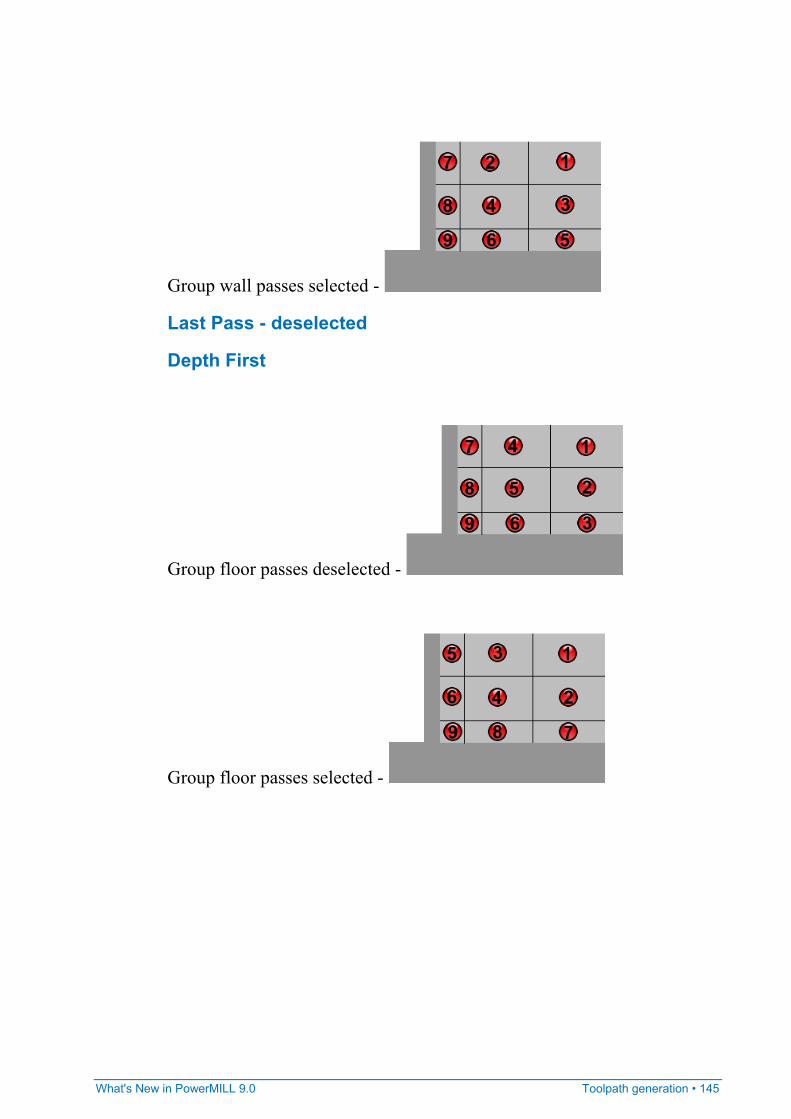
What's New in PowerMILL 9.0 Toolpath generation • 145
Group wall passes selected -
Last Pass - deselected
Depth First
Group floor passes deselected -
Group floor passes selected -
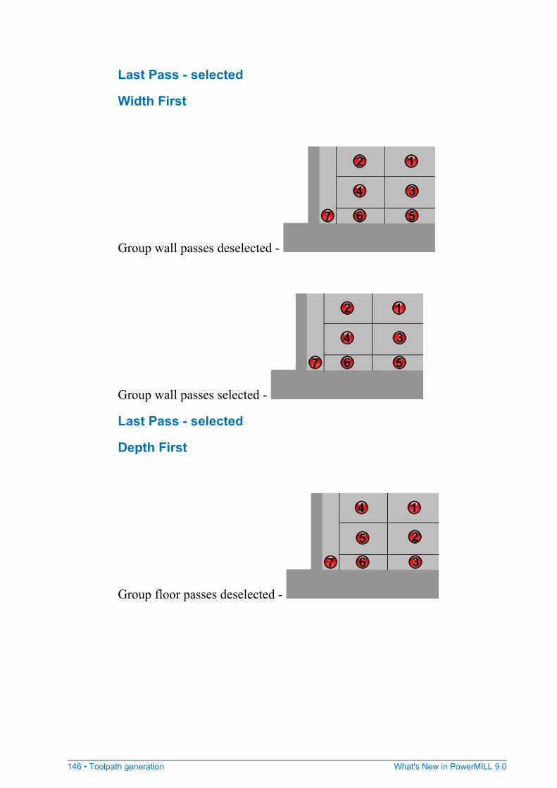
146 • Toolpath generation What's New in PowerMILL 9.0
Last Pass - selected
Width First
Group wall passes deselected -
Group wall passes selected -
Last Pass - selected
Depth First
Group floor passes deselected -
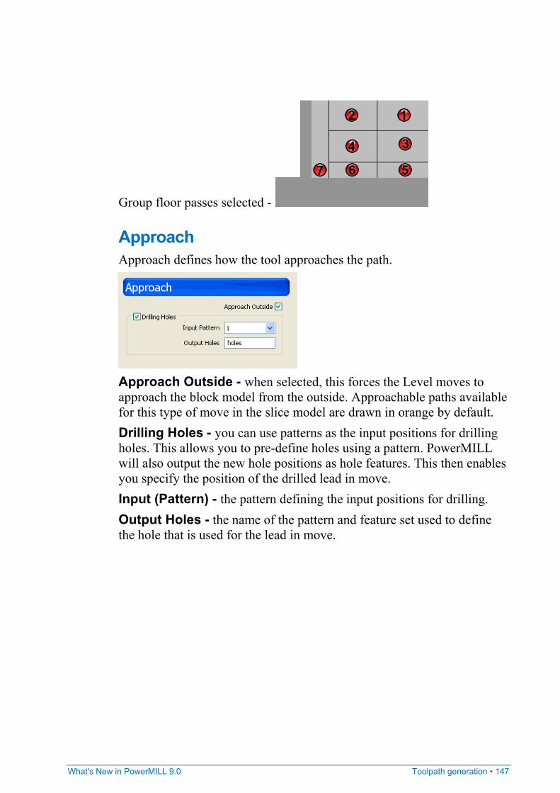
What's New in PowerMILL 9.0 Toolpath generation • 147
Group floor passes selected -
Approach Approach defines how the tool approaches the path.
Approach Outside - when selected, this forces the Level moves to approach the block model from the outside. Approachable paths available for this type of move in the slice model are drawn in orange by default. Drilling Holes - you can use patterns as the input positions for drilling holes. This allows you to pre-define holes using a pattern. PowerMILL will also output the new hole positions as hole features. This then enables you specify the position of the drilled lead in move. Input (Pattern) - the pattern defining the input positions for drilling. Output Holes - the name of the pattern and feature set used to define the hole that is used for the lead in move.
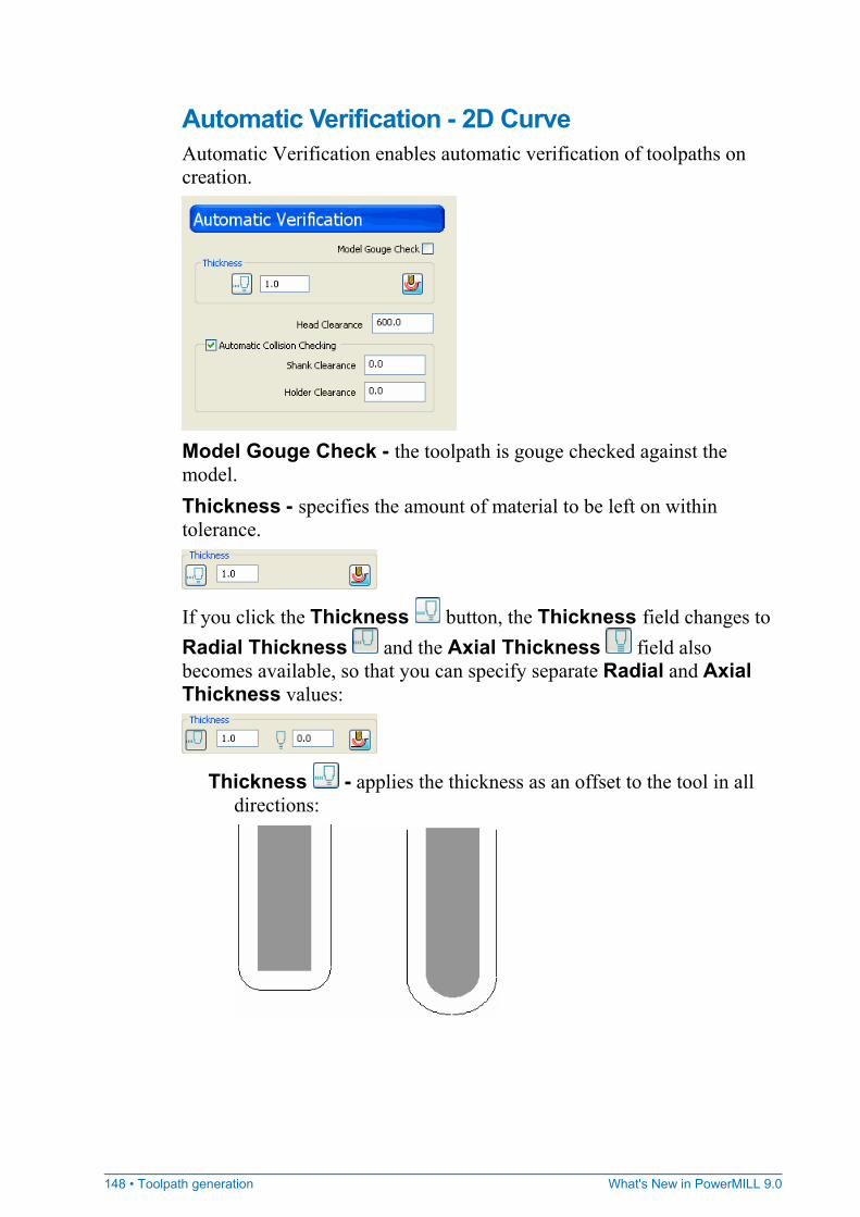
148 • Toolpath generation What's New in PowerMILL 9.0
Automatic Verification - 2D Curve Automatic Verification enables automatic verification of toolpaths on creation.
Model Gouge Check - the toolpath is gouge checked against the model. Thickness - specifies the amount of material to be left on within tolerance.
If you click the Thickness button, the Thickness field changes to Radial Thickness and the Axial Thickness field also becomes available, so that you can specify separate Radial and Axial Thickness values:
Thickness - applies the thickness as an offset to the tool in all directions:
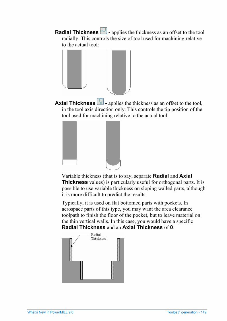
What's New in PowerMILL 9.0 Toolpath generation • 149
Radial Thickness - applies the thickness as an offset to the tool radially. This controls the size of tool used for machining relative to the actual tool:
Axial Thickness - applies the thickness as an offset to the tool, in the tool axis direction only. This controls the tip position of the tool used for machining relative to the actual tool:
Variable thickness (that is to say, separate Radial and Axial Thickness values) is particularly useful for orthogonal parts. It is possible to use variable thickness on sloping walled parts, although it is more difficult to predict the results. Typically, it is used on flat bottomed parts with pockets. In aerospace parts of this type, you may want the area clearance toolpath to finish the floor of the pocket, but to leave material on the thin vertical walls. In this case, you would have a specific Radial Thickness and an Axial Thickness of 0:
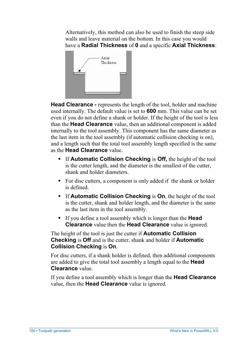
150 • Toolpath generation What's New in PowerMILL 9.0
Alternatively, this method can also be used to finish the steep side walls and leave material on the bottom. In this case you would have a Radial Thickness of 0 and a specific Axial Thickness:
Head Clearance - represents the length of the tool, holder and machine used internally. The default value is set to 600 mm. This value can be set even if you do not define a shank or holder. If the height of the tool is less than the Head Clearance value, then an additional component is added internally to the tool assembly. This component has the same diameter as the last item in the tool assembly (if automatic collision checking is on), and a length such that the total tool assembly length specified is the same as the Head Clearance value.
If Automatic Collision Checking is Off, the height of the tool is the cutter length, and the diameter is the smallest of the cutter, shank and holder diameters.
For disc cutters, a component is only added if the shank or holder is defined.
If Automatic Collision Checking is On, the height of the tool is the cutter, shank and holder length, and the diameter is the same as the last item in the tool assembly.
If you define a tool assembly which is longer than the Head Clearance value then the Head Clearance value is ignored.
The height of the tool is just the cutter if Automatic Collision Checking is Off and is the cutter, shank and holder if Automatic Collision Checking is On. For disc cutters, if a shank holder is defined, then additional components are added to give the total tool assembly a length equal to the Head Clearance value. If you define a tool assembly which is longer than the Head Clearance value, then the Head Clearance value is ignored.

What's New in PowerMILL 9.0 Toolpath generation • 151
Automatic Collision Checking - controls collision checking of toolpaths during toolpath calculation. When selected, the tool shank and holder are collision checked. The resulting toolpath only contains the non-colliding (safe) moves. This can lead to gaps in the toolpath. If unselected, the tool shank and holder are not collision checked.
Collision checking using the Toolpath Verification dialog will check against shank and holder regardless of this option.
Shank Clearance - represents a specified “safe” area around the tool shank which is taken into account when checking for collisions. Holder Clearance - represents a specified “safe” area around the tool holder which is taken into account when checking for collisions.
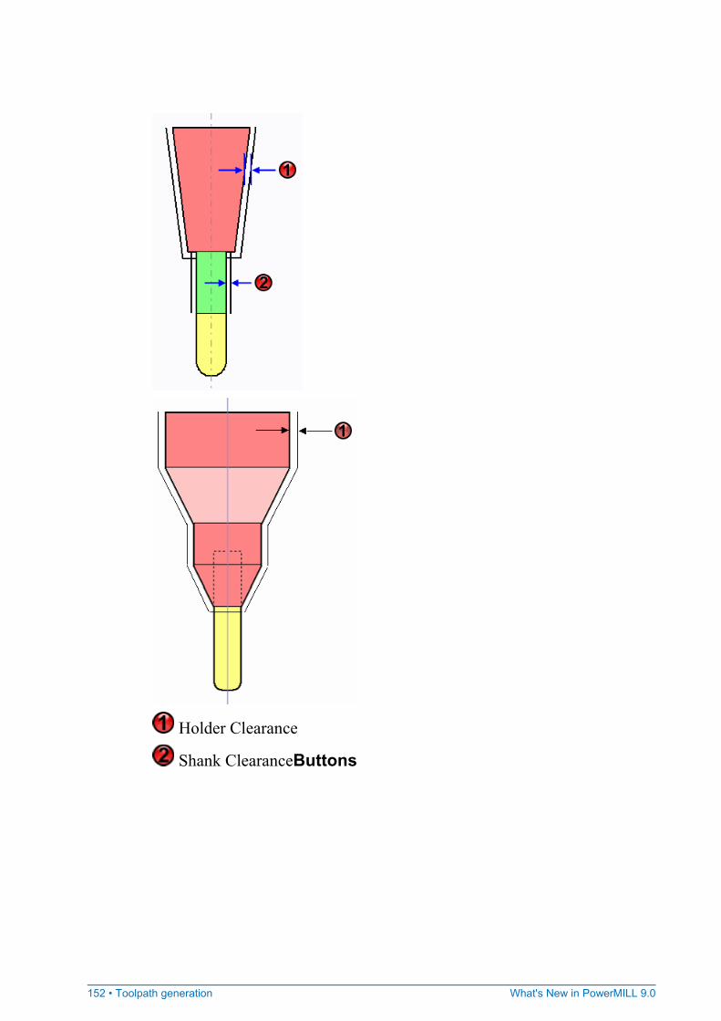
152 • Toolpath generation What's New in PowerMILL 9.0
Holder Clearance
Shank ClearanceButtons
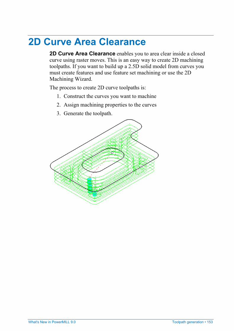
What's New in PowerMILL 9.0 Toolpath generation • 153
2D Curve Area Clearance 2D Curve Area Clearance enables you to area clear inside a closed curve using raster moves. This is an easy way to create 2D machining toolpaths. If you want to build up a 2.5D solid model from curves you must create features and use feature set machining or use the 2D Machining Wizard. The process to create 2D curve toolpaths is:
1. Construct the curves you want to machine 2. Assign machining properties to the curves 3. Generate the toolpath.

154 • Toolpath generation What's New in PowerMILL 9.0
There are several tabs associated with curve area clearance:
Curve Area Clearance - the main page used to define a curve area clearance toolpath Cut Distances (see page 126) - enables multiple passes Draft Angle (see page 130) - creates toolpaths with draft angles Rest (see page 131) - creates a curve profiling toolpath from a reference toolpath Offset (see page 132) - enables a spiral toolpath to minimises lifts Raster (see page 160) - the angle of machining High Speed (see page 136) - smoothing options to avoid sharp changes in tool direction when high speed machining Order (see page 143) - controls the order of machining Approach (see page 147) - defines how the tool approaches the path Automatic Verification (see page 148) - enables automatic verification of toolpaths on creation.
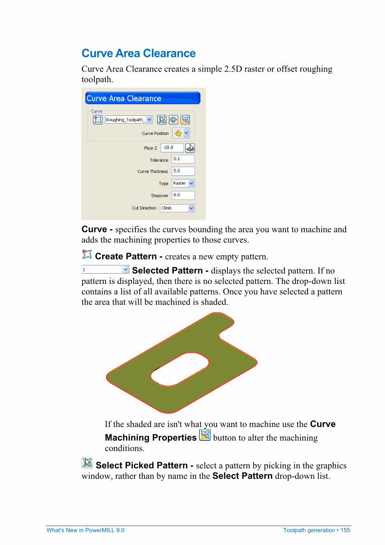
What's New in PowerMILL 9.0 Toolpath generation • 155
Curve Area Clearance Curve Area Clearance creates a simple 2.5D raster or offset roughing toolpath.
Curve - specifies the curves bounding the area you want to machine and adds the machining properties to those curves.
Create Pattern - creates a new empty pattern. Selected Pattern - displays the selected pattern. If no
pattern is displayed, then there is no selected pattern. The drop-down list contains a list of all available patterns. Once you have selected a pattern the area that will be machined is shaded.
If the shaded are isn't what you want to machine use the Curve Machining Properties button to alter the machining conditions.
Select Picked Pattern - select a pattern by picking in the graphics window, rather than by name in the Select Pattern drop-down list.
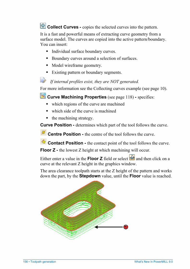
156 • Toolpath generation What's New in PowerMILL 9.0
Collect Curves - copies the selected curves into the pattern. It is a fast and powerful means of extracting curve geometry from a surface model. The curves are copied into the active pattern/boundary. You can insert:
Individual surface boundary curves. Boundary curves around a selection of surfaces. Model wireframe geometry. Existing pattern or boundary segments.
If internal profiles exist, they are NOT generated. For more information see the Collecting curves example (see page 10).
Curve Machining Properties (see page 118) - specifies: which regions of the curve are machined which side of the curve is machined the machining strategy.
Curve Position - determines which part of the tool follows the curve.
Centre Position - the centre of the tool follows the curve.
Contact Position - the contact point of the tool follows the curve. Floor Z - the lowest Z height at which machining will occur.
Either enter a value in the Floor Z field or select and then click on a curve at the relevant Z height in the graphics window. The area clearance toolpath starts at the Z height of the pattern and works down the part, by the Stepdown value, until the Floor value is reached.
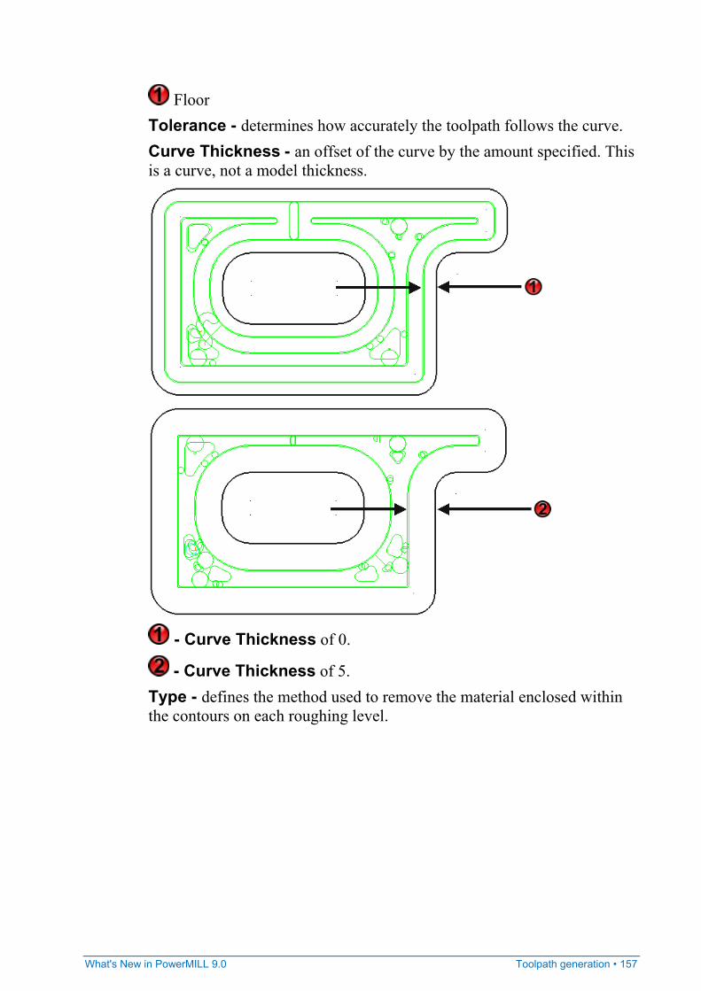
What's New in PowerMILL 9.0 Toolpath generation • 157
Floor Tolerance - determines how accurately the toolpath follows the curve. Curve Thickness - an offset of the curve by the amount specified. This is a curve, not a model thickness.
- Curve Thickness of 0.
- Curve Thickness of 5. Type - defines the method used to remove the material enclosed within the contours on each roughing level.
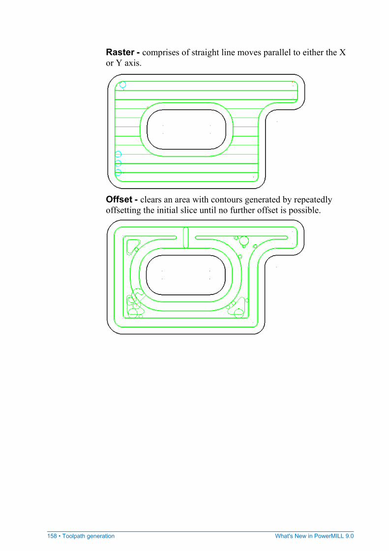
158 • Toolpath generation What's New in PowerMILL 9.0
Raster - comprises of straight line moves parallel to either the X or Y axis.
Offset - clears an area with contours generated by repeatedly offsetting the initial slice until no further offset is possible.

What's New in PowerMILL 9.0 Toolpath generation • 159
Stepover - defines the distance between successive area clearance passes at a single Z height.
Cut Direction - determines the milling technology.
Any - creates toolpaths using both conventional and climb milling, as appropriate. This minimises the tool lifts and tool travel. Climb - creates toolpaths using only climb milling. Conventional - creates toolpaths using only conventional or 'upcut' milling.
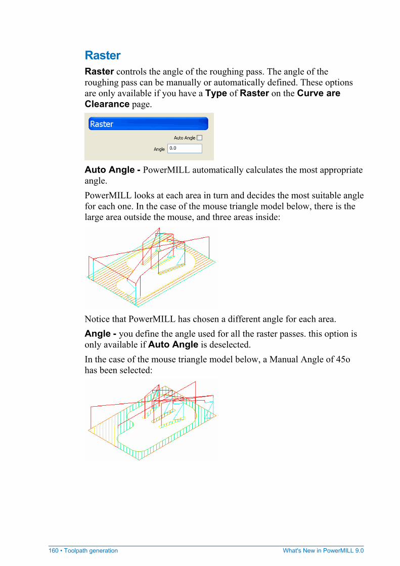
160 • Toolpath generation What's New in PowerMILL 9.0
Raster Raster controls the angle of the roughing pass. The angle of the roughing pass can be manually or automatically defined. These options are only available if you have a Type of Raster on the Curve are Clearance page.
Auto Angle - PowerMILL automatically calculates the most appropriate angle. PowerMILL looks at each area in turn and decides the most suitable angle for each one. In the case of the mouse triangle model below, there is the large area outside the mouse, and three areas inside:
Notice that PowerMILL has chosen a different angle for each area. Angle - you define the angle used for all the raster passes. this option is only available if Auto Angle is deselected. In the case of the mouse triangle model below, a Manual Angle of 45o has been selected:
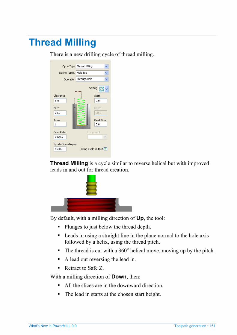
What's New in PowerMILL 9.0 Toolpath generation • 161
Thread Milling There is a new drilling cycle of thread milling.
Thread Milling is a cycle similar to reverse helical but with improved leads in and out for thread creation.
By default, with a milling direction of Up, the tool:
Plunges to just below the thread depth. Leads in using a straight line in the plane normal to the hole axis
followed by a helix, using the thread pitch. The thread is cut with a 360 helical move, moving up by the pitch. A lead out reversing the lead in. Retract to Safe Z.
With a milling direction of Down, then: All the slices are in the downward direction. The lead in starts at the chosen start height.
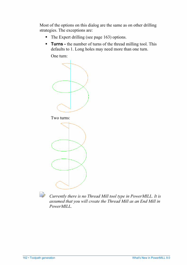
162 • Toolpath generation What's New in PowerMILL 9.0
Most of the options on this dialog are the same as on other drilling strategies. The exceptions are:
The Expert drilling (see page 163) options. Turns - the number of turns of the thread milling tool. This
defaults to 1. Long holes may need more than one turn. One turn:
Two turns:
Currently there is no Thread Mill tool type in PowerMILL. It is assumed that you will create the Thread Mill as an End Mill in PowerMILL.
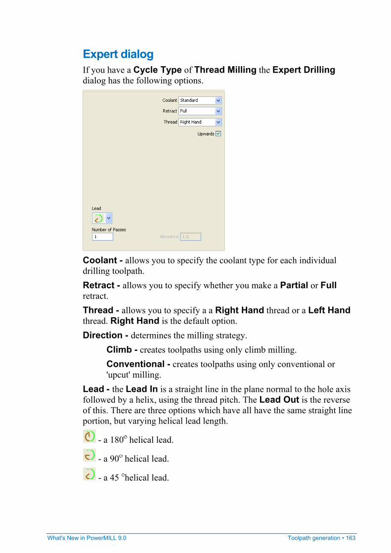
What's New in PowerMILL 9.0 Toolpath generation • 163
Expert dialog If you have a Cycle Type of Thread Milling the Expert Drilling dialog has the following options.
Coolant - allows you to specify the coolant type for each individual drilling toolpath. Retract - allows you to specify whether you make a Partial or Full retract. Thread - allows you to specify a a Right Hand thread or a Left Hand thread. Right Hand is the default option. Direction - determines the milling strategy.
Climb - creates toolpaths using only climb milling. Conventional - creates toolpaths using only conventional or 'upcut' milling.
Lead - the Lead In is a straight line in the plane normal to the hole axis followed by a helix, using the thread pitch. The Lead Out is the reverse of this. There are three options which have all have the same straight line portion, but varying helical lead length.
- a 180 helical lead.
- a 90 helical lead.
- a 45 helical lead.
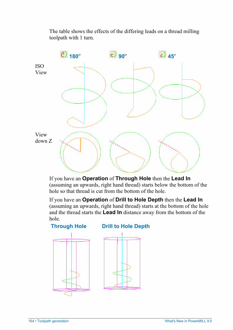
164 • Toolpath generation What's New in PowerMILL 9.0
The table shows the effects of the differing leads on a thread milling toolpath with 1 turn.
180 90 45
ISO View
View down Z
If you have an Operation of Through Hole then the Lead In (assuming an upwards, right hand thread) starts below the bottom of the hole so that thread is cut from the bottom of the hole. If you have an Operation of Drill to Hole Depth then the Lead In (assuming an upwards, right hand thread) starts at the bottom of the hole and the thread starts the Lead In distance away from the bottom of the hole. Through Hole Drill to Hole Depth
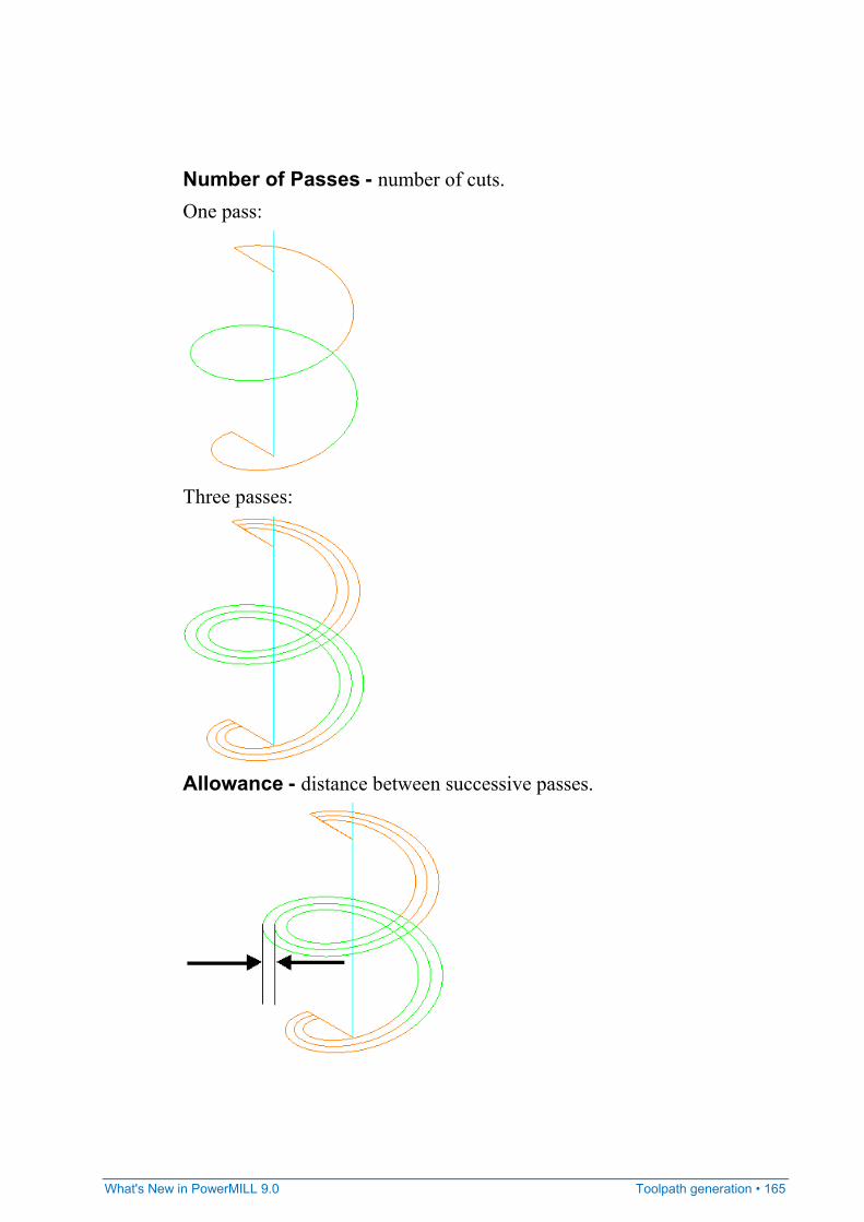
What's New in PowerMILL 9.0 Toolpath generation • 165
Number of Passes - number of cuts. One pass:
Three passes:
Allowance - distance between successive passes.
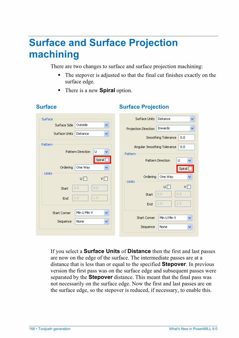
166 • Toolpath generation What's New in PowerMILL 9.0
Surface and Surface Projection machining
There are two changes to surface and surface projection machining: The stepover is adjusted so that the final cut finishes exactly on the
surface edge. There is a new Spiral option.
Surface Surface Projection
If you select a Surface Units of Distance then the first and last passes are now on the edge of the surface. The intermediate passes are at a distance that is less than or equal to the specified Stepover. In previous version the first pass was on the surface edge and subsequent passes were separated by the Stepover distance. This meant that the final pass was not necessarily on the surface edge. Now the first and last passes are on the surface edge, so the stepover is reduced, if necessary, to enable this.
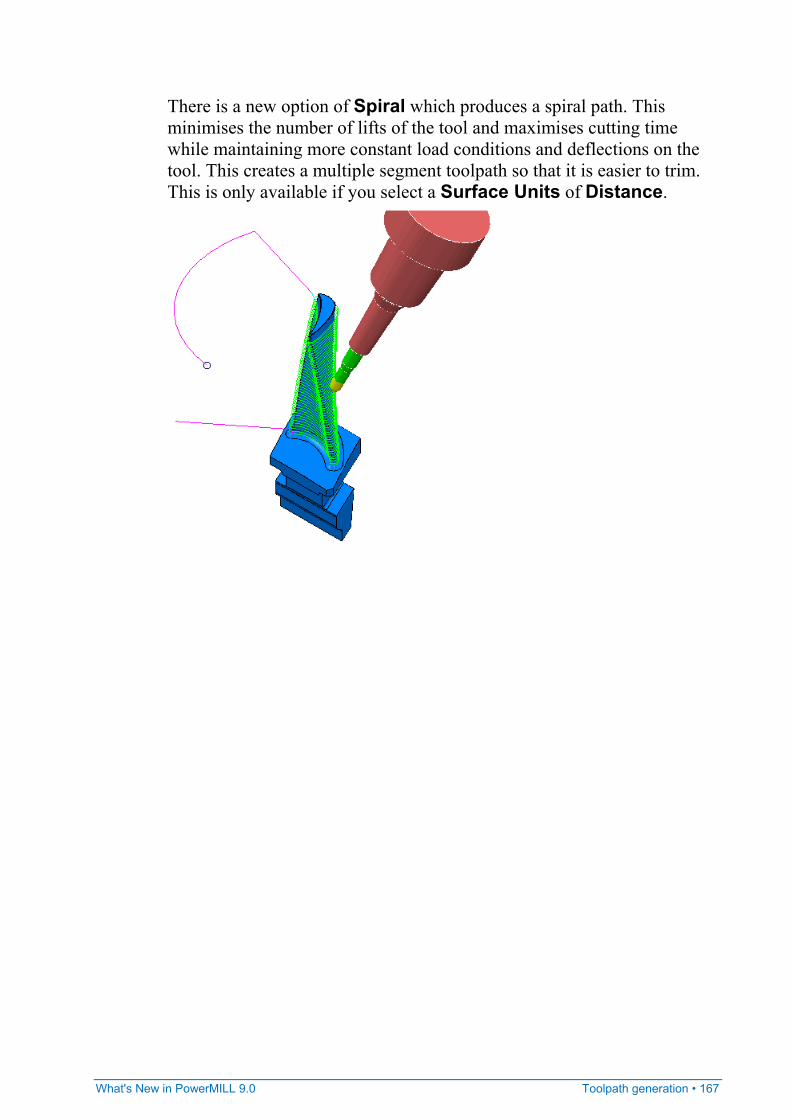
What's New in PowerMILL 9.0 Toolpath generation • 167
There is a new option of Spiral which produces a spiral path. This minimises the number of lifts of the tool and maximises cutting time while maintaining more constant load conditions and deflections on the tool. This creates a multiple segment toolpath so that it is easier to trim. This is only available if you select a Surface Units of Distance.

168 • Toolpath generation What's New in PowerMILL 9.0
Swarf machining There are a couple of swarf machining enhancements:
You can now generate surface swarf toolpaths where the selected surfaces have different component thicknesses.
There are improvements to rulings used for wireframe swarf machining.
You can now create wireframe swarf machining from curves, without a model. This is possible when you don't want to check the toolpath against a model by deselecting Gouge Check.
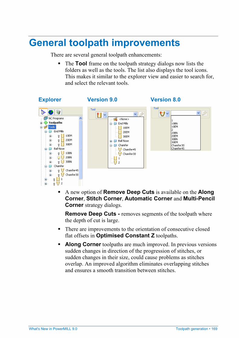
What's New in PowerMILL 9.0 Toolpath generation • 169
General toolpath improvements There are several general toolpath enhancements:
The Tool frame on the toolpath strategy dialogs now lists the folders as well as the tools. The list also displays the tool icons. This makes it similar to the explorer view and easier to search for, and select the relevant tools.
Explorer Version 9.0 Version 8.0
A new option of Remove Deep Cuts is available on the Along
Corner, Stitch Corner, Automatic Corner and Multi-Pencil Corner strategy dialogs. Remove Deep Cuts - removes segments of the toolpath where the depth of cut is large.
There are improvements to the orientation of consecutive closed flat offsets in Optimised Constant Z toolpaths.
Along Corner toolpaths are much improved. In previous versions sudden changes in direction of the progression of stitches, or sudden changes in their size, could cause problems as stitches overlap. An improved algorithm eliminates overlapping stitches and ensures a smooth transition between stitches.

170 • Toolpath verification What's New in PowerMILL 9.0
Collision Checker There are several improvements to collision checking.
In many cases collision checking is now faster. The improvements are particularly noticeable on large models.
PowerMILL reports on the depth of a collision and the required tool overhang even if the change needed is very small.
The tool in locked toolpaths can now be replaced during collision checking.
Toolpath verification
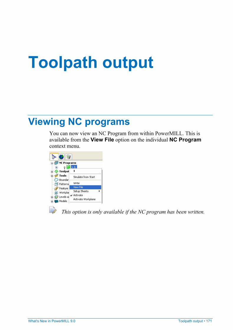
What's New in PowerMILL 9.0 Toolpath output • 171
Viewing NC programs You can now view an NC Program from within PowerMILL. This is available from the View File option on the individual NC Program context menu.
This option is only available if the NC program has been written.
Toolpath output
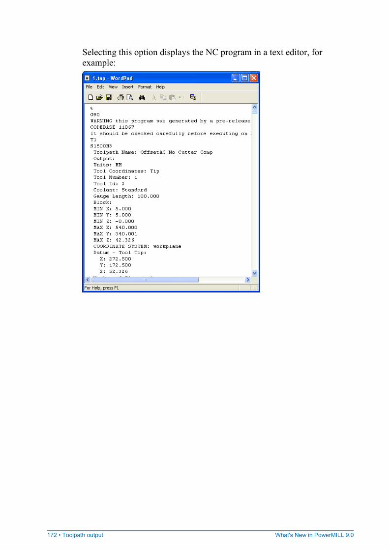
172 • Toolpath output What's New in PowerMILL 9.0
Selecting this option displays the NC program in a text editor, for example:
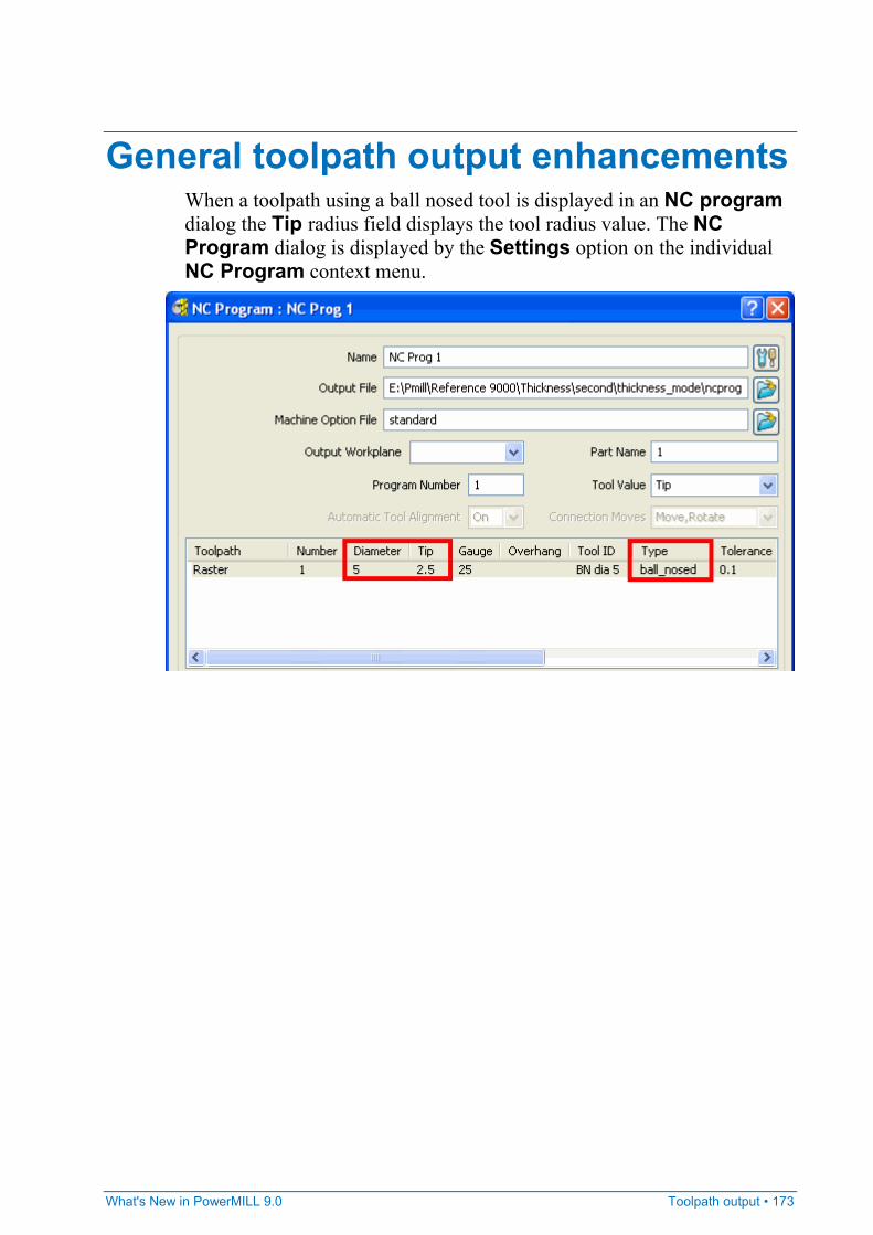
What's New in PowerMILL 9.0 Toolpath output • 173
General toolpath output enhancements When a toolpath using a ball nosed tool is displayed in an NC program dialog the Tip radius field displays the tool radius value. The NC Program dialog is displayed by the Settings option on the individual NC Program context menu.
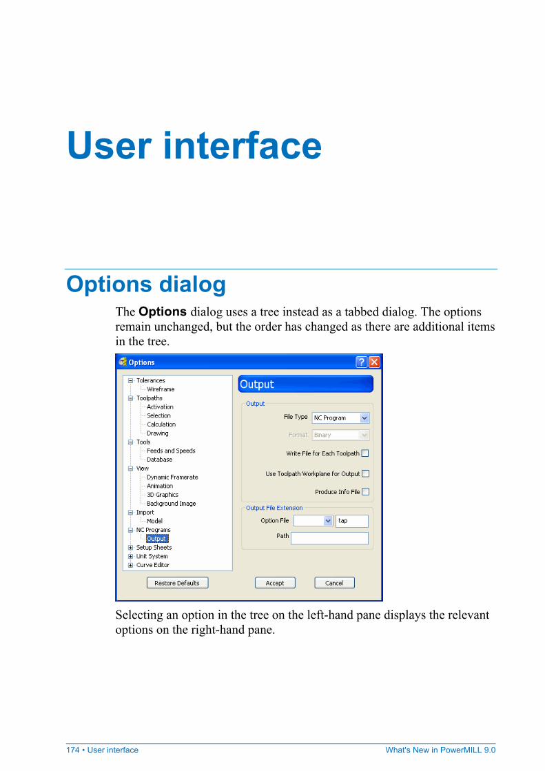
174 • User interface What's New in PowerMILL 9.0
Options dialog The Options dialog uses a tree instead as a tabbed dialog. The options remain unchanged, but the order has changed as there are additional items in the tree.
Selecting an option in the tree on the left-hand pane displays the relevant options on the right-hand pane.
User interface
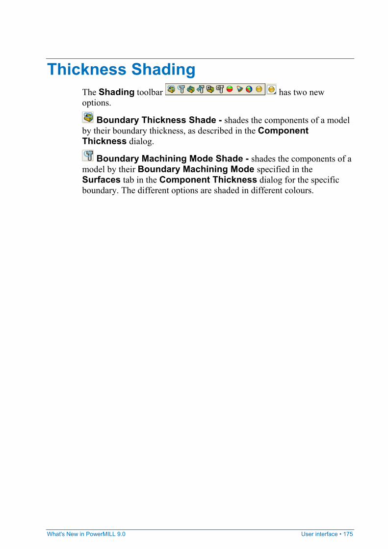
What's New in PowerMILL 9.0 User interface • 175
Thickness Shading The Shading toolbar has two new options.
Boundary Thickness Shade - shades the components of a model by their boundary thickness, as described in the Component Thickness dialog.
Boundary Machining Mode Shade - shades the components of a model by their Boundary Machining Mode specified in the Surfaces tab in the Component Thickness dialog for the specific boundary. The different options are shaded in different colours.
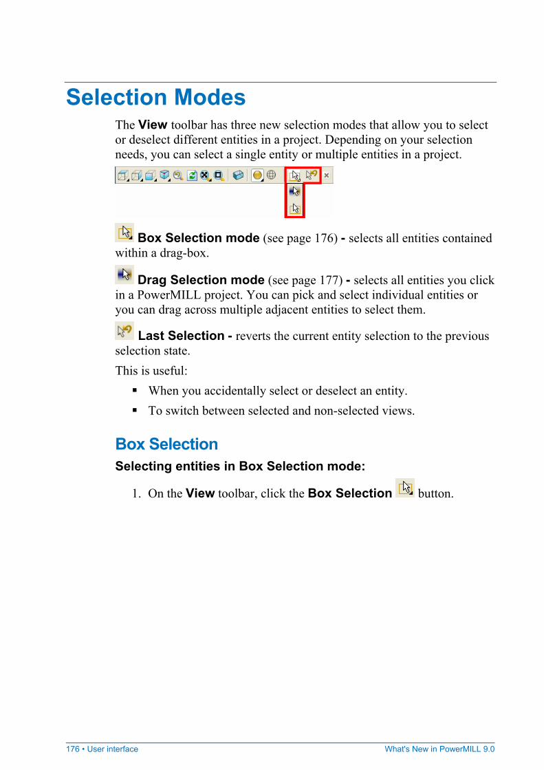
176 • User interface What's New in PowerMILL 9.0
Selection Modes The View toolbar has three new selection modes that allow you to select or deselect different entities in a project. Depending on your selection needs, you can select a single entity or multiple entities in a project.
Box Selection mode (see page 176) - selects all entities contained within a drag-box.
Drag Selection mode (see page 177) - selects all entities you click in a PowerMILL project. You can pick and select individual entities or you can drag across multiple adjacent entities to select them.
Last Selection - reverts the current entity selection to the previous selection state. This is useful:
When you accidentally select or deselect an entity. To switch between selected and non-selected views.
Box Selection Selecting entities in Box Selection mode:
1. On the View toolbar, click the Box Selection button.

What's New in PowerMILL 9.0 User interface • 177
2. Click and drag the mouse to create a box over the entities you want to select.
PowerMILL selects all entities in the selection box.
To deselect entities from a group of selected entities, hold down the Ctrl key and click the entities you want to deselect.
If you accidentally deselect your selections, click the Last Selection button to revert back to the previous selection state.
Drag Selection Selecting entities in Drag Selection mode:
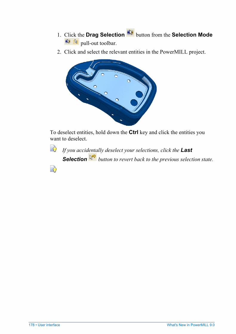
178 • User interface What's New in PowerMILL 9.0
1. Click the Drag Selection button from the Selection Mode pull-out toolbar.
2. Click and select the relevant entities in the PowerMILL project.
To deselect entities, hold down the Ctrl key and click the entities you want to deselect.
If you accidentally deselect your selections, click the Last Selection button to revert back to the previous selection state.
What's New in PowerMILL 9.0 Index • 179
A Applying cutter compensation • 73 Arc • 47, 49, 52
B Blanking • 65 Block • 61 Break segment • 20
C Chamfer milling • 104 Circle • 47, 49, 52 Collect curves • 10 Collision checker • 169 Curve
Arc • 47, 49, 52 Break segment • 20 Circle • 47, 49, 52 Collect curves • 10 Cut segment • 20 Line • 42, 52 Merge segment • 21 Mirror • 30 Move • 26 Rotate • 29 Scale • 32 Workplane • 35
Cut segment • 20 Cutter compensation • 71
Applying cutter compensation • 73 Drawing cutter compensation • 75 Previous versions • 77 Repairing Cutter Compensation • 78
D Drawing cutter compensation • 75 Drilling
Thread milling • 160
F Face milling • 99 Fillet • 49
H Hiding model components
Blanking • 65
J Joins
Join close • 19 Join straight • 16 Join tangent • 18
Index
180 • Index What's New in PowerMILL 9.0
L Line • 42, 52
M Machining
Chamfer milling • 104 Face milling • 99 Machining Strategy dialog • 80 Surface Machining • 165 Surface projection machining • 165 Swarf machining • 167 Thread milling • 160
Machining Strategy dialog • 80 Merge segment • 21 Milling
Chamfer milling • 104 Face milling • 99 Thread milling • 160
Mirror • 30 Move • 26 Move origin • 27
N NC programs
View NC programs • 170
O Options dialog • 173
R Repairing Cutter Compensation • 78 Rotate • 29
S Scale • 32 Segment
Cut segment • 20 Merge segment • 21
Shade Thickness shading • 174
Surface Machining • 165 Surface projection machining • 165 Swarf machining • 167
T Tapered tipped tool • 68 Thickness shading • 174 Thread milling • 160 Tool folders • 168 Transformation
Mirror • 30 Move • 26 Move origin • 27 Rotate • 29 Scale • 32
V View
Thickness shading • 174 View NC programs • 170
W Workplane • 35
Move origin • 27