what's left to understand about srf? hasan padamsee cornell university (soon to be…fermilab)
TRANSCRIPT
What's left to understand about SRF?
Hasan PadamseeCornell University
(soon to be…Fermilab)

First, Some Remarks about Peter• I had two occasions to work with Peter, • One short in 1978 • And one long between 1981 – 1987• At Cornell Peter worked on Muffin-Tin Cavities
for high energy synchrotrons
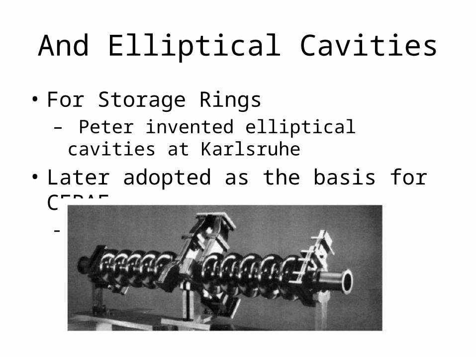
And Elliptical Cavities
• For Storage Rings– Peter invented elliptical cavities at Karlsruhe
• Later adopted as the basis for CEBAF– Performance 5 – 8 MV/m

A Page from the Past (1982) : Peter’s Logbook• At the time, Muffin-Tin
cavities showed very colorful behavior!– Multipacting, thermal
breakdown, field emission.
• Peter played a MAJOR role in understanding and solving all such problems
Peter’s Impact
• Throughout his career Peter always pushed hard –
• To help advance the field• Both for basic understanding and for projects • He has consistently been a driving force • Asking the tough questions, breaking barriers,
opening new pathways.

So, What Remains To Be Understood?
• Much work has been done to understand the topics I will cover• Many explanations have been put forward.• So I cannot say categorically that these phenomena are “not
understood” – Because many believe they understand some of this stuff
• But is the understanding universally accepted?• Mostly NOT• That is why I pick these topics, as• “remain to be understood”• My apologies if I don’t show all the possible “explanations” put
forward, just some.
Has Peter left us anything to work on?
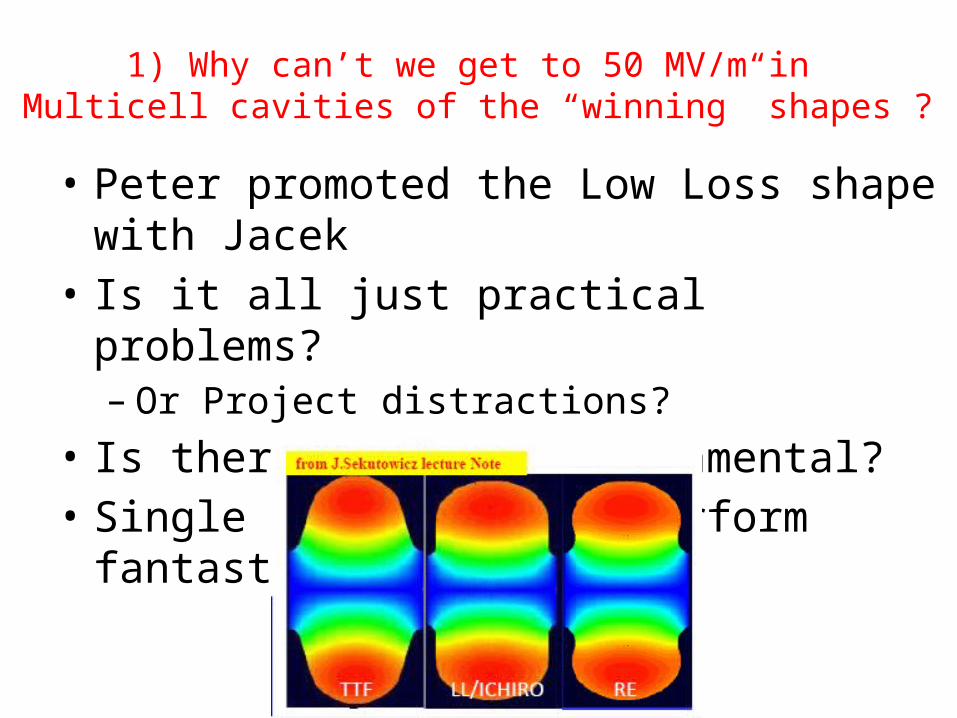
1) Why can’t we get to 50 MV/m in Multicell cavities of the “winning” shapes ?
• Peter promoted the Low Loss shape with Jacek• Is it all just practical problems?
– Or Project distractions?• Is there something fundamental?• Single cell cavities perform fantastic!

Epk > 120 MV/m
Hpk > 190 mT
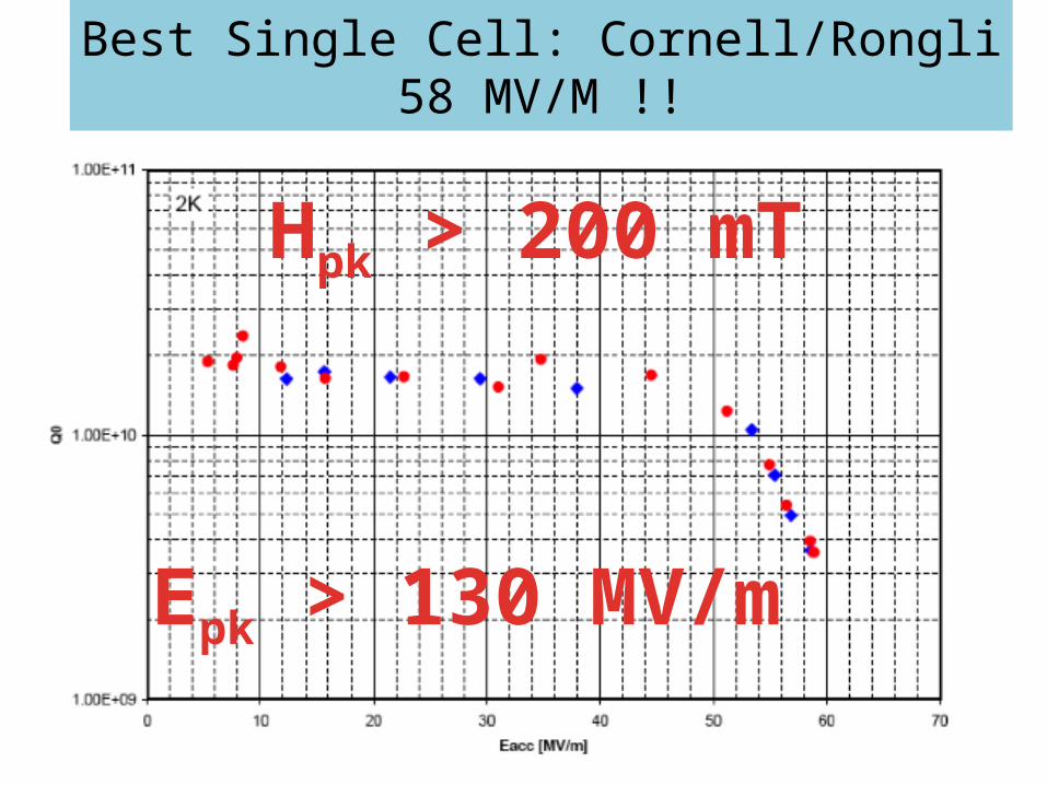
Best Single Cell: Cornell/Rongli58 MV/M !!
Epk > 130 MV/m
Hpk > 200 mT
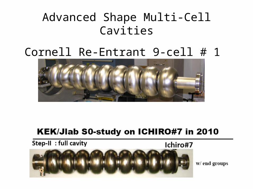
Cornell Re-Entrant 9-cell # 1
Advanced Shape Multi-Cell Cavities
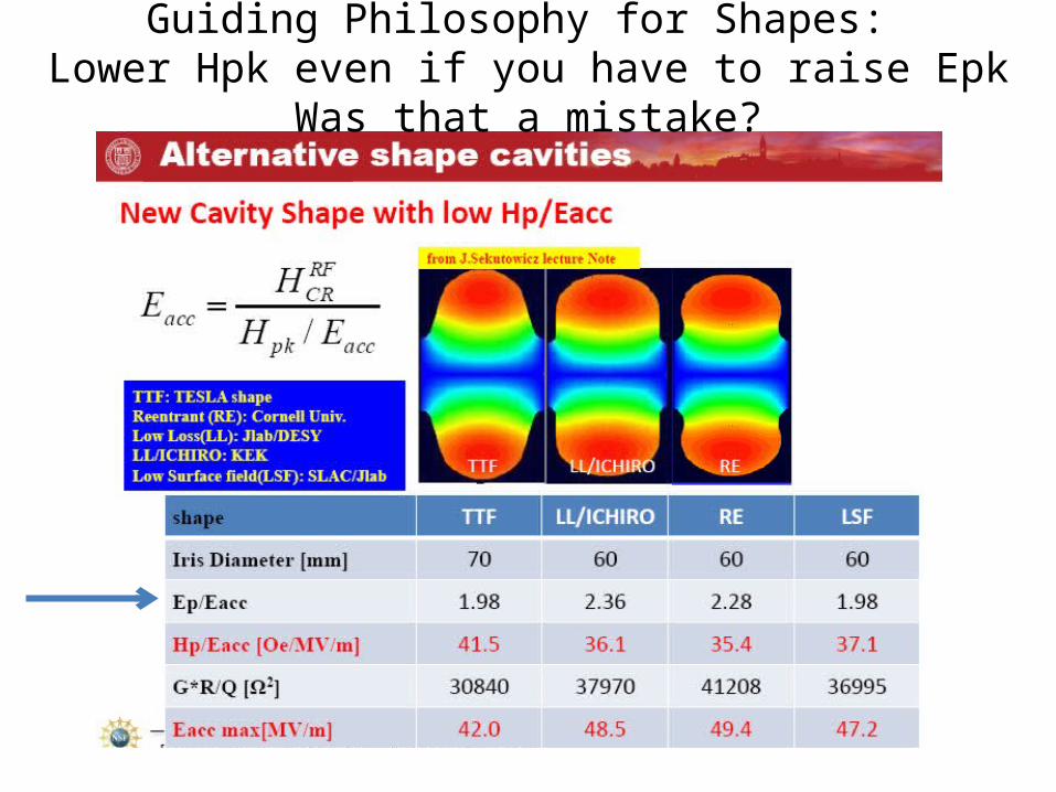
Guiding Philosophy for Shapes: Lower Hpk even if you have to raise Epk
Was that a mistake?

So Field Emission X-rays Swamp Performance

42 MV/m Demonstrated With
How to get rid of Field Emission?
• Peter demonstrated this powerful weapon against Field Emission!
• HPR at 100 bar• Is HPR at 100 bar good enough to get rid of FE
above Epk > 100 MV/m?• OR• Should we get serious about other FE
reduction methods, like snow cleaning?
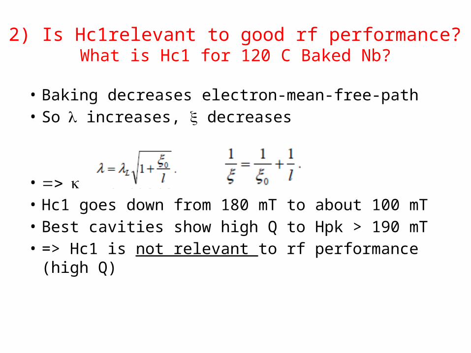
2) Is Hc1relevant to good rf performance?What is Hc1 for 120 C Baked Nb?
• Baking decreases electron-mean-free-path• So l increases, x decreases
• => k increases • Hc1 goes down from 180 mT to about 100 mT• Best cavities show high Q to Hpk > 190 mT • => Hc1 is not relevant to rf performance (high Q)
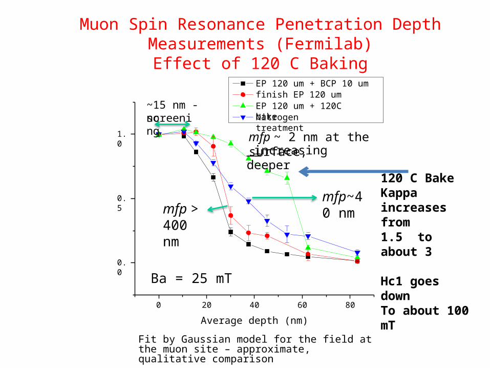
Muon Spin Resonance Penetration Depth Measurements (Fermilab)
Effect of 120 C Baking
Ba = 25 mT
0 20 40 60 80
Average depth (nm)
Fit by Gaussian model for the field at the muon site – approximate, qualitative comparison
0.0
0.5
1.0
EP 120 um + BCP 10 um finish EP 120 umEP 120 um + 120C bakeNitrogen treatment
mfp ~ 2 nm at the surface, increasing deeper
~15 nm - noscreening
mfp~40 nmmfp >
400 nm
120 C BakeKappa increases from 1.5 to about 3
Hc1 goes downTo about 100 mT

Fundamental RF Critical Field MeasurementN. Valles Cornell
Eacc (max) = 2000/35.4 = 61 MV/m !!
Hc1 (T)
Hrf-crit >> Hc1Hrf-crit ~ Hsh
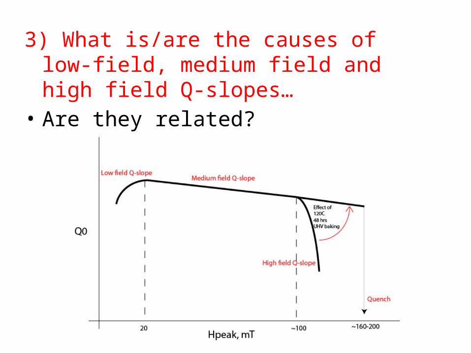
3) What is/are the causes of low-field, medium field and high field Q-slopes…
• Are they related?
A Promising Model
• Several possible answers have been proposed– Apologies if I don’t pick your favorite one
• But the basic question is still unanswered - to everyone’s satisfaction
• A promising model is that Medium and High Field Q-slopes arise from a “mild” form of the H-Q-Disease
• Nb-H islands form but are Superconducting due to their proximity with Nb
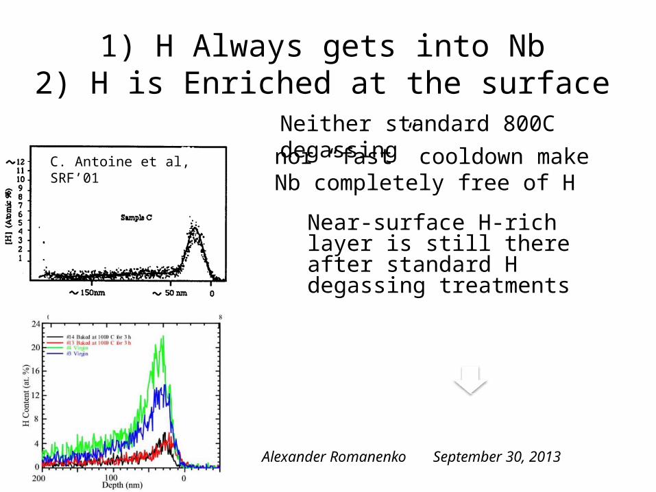
Neither standard 800C degassing
nor “fast” cooldown make Nb completely free of H
C. Antoine et al, SRF’01
Near-surface H-rich layer is still there after standard H degassing treatments
1) H Always gets into Nb2) H is Enriched at the surface
September 30, 2013Alexander Romanenko
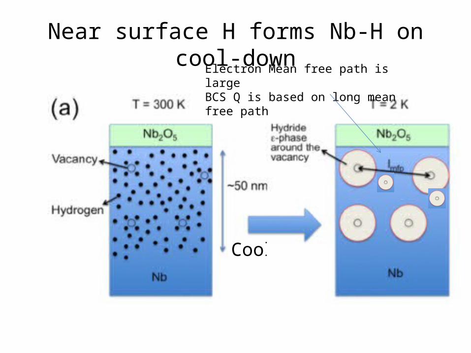
Near surface H forms Nb-H on cool-down
Cool down
Electron Mean free path is largeBCS Q is based on long mean free path

High and Medium Field Q-Slopes
• RF Losses of SC islands increase with increasing rf field (proximity effect gets weaker)– Medium Field Q-slope
• Largest island becomes normal at the onset field – High field Q-slope starts
• Smaller islands remain SC but increase losses with field – Continued Medium field Q-slope

Effect of 120C baking
120Cbaking
T= 300K T= 300K
A. Romanenko, C. J. Edwardson, P. G. Coleman, P. J. Simpson, Appl. Phys. Lett. 102, 232601 (2013)
Free interstitial hydrogen
~50 nm
Oxide Oxide
120 C Baking EffectVacancies trap H, Prevent Nb-H formation
September 30, 2013 Alexander Romanenko 23
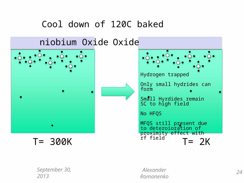
Effect of 120C baking
Hydrogen trapped
Only small hydrides can form
Small Hyrdides remain SC to high field
No HFQS
MFQS still present due to deteroioration of proximity effect with rf field
Cool down of 120C baked niobium
Oxide Oxide
T= 300K T= 2K
24September 30, 2013 Alexander Romanenko
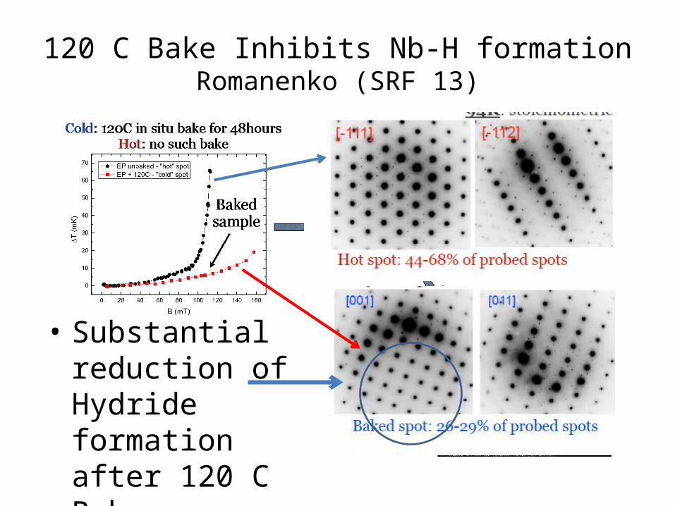
120 C Bake Inhibits Nb-H formationRomanenko (SRF 13)
• Substantial reduction of Hydride formation after 120 C Bake
C1 03 E5 T=1.7K
1E+08
1E+09
1E+10
1E+11
0 5 10 15 20 25 30 35 40 45
Eacc (MV/m)
Qo QUENCH
qq e-
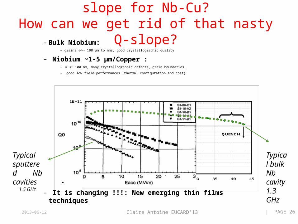
– Bulk Niobium:– grains >~ 100 µm to mms, good crystallographic quality
– Niobium ~1-5 µm/Copper : – <~ 100 nm, many crystallographic defects, grain boundaries…
– good low field performances (thermal configuration and cost)
• – It is changing !!!: New emerging thin films techniques
4) What is the cause of the Q-slope for Nb-Cu?How can we get rid of that nasty Q-slope?
2013-06-12 Claire Antoine EUCARD'13 | PAGE 26
Typical sputtered Nb cavities
1.5 GHz
Typical bulk Nb cavity1.3 GHz
LCWS12, 10/22-26, 2012 27
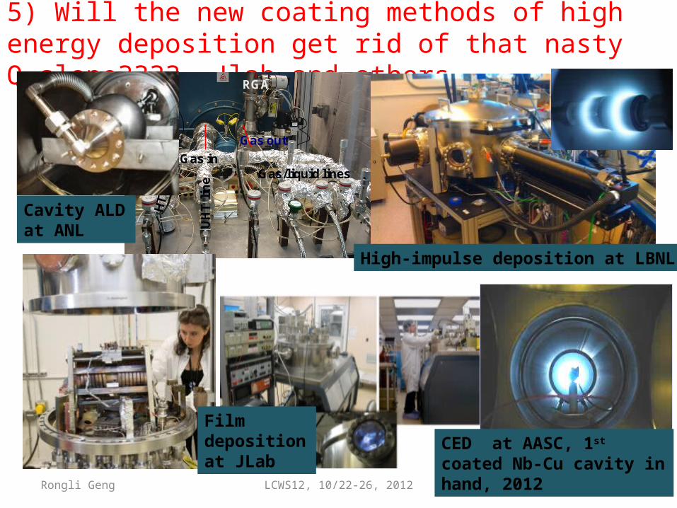
5) Will the new coating methods of high energy deposition get rid of that nasty Q-slope???? Jlab and others
Rongli Geng
Gas in
Gas out
Gas/liquid lines
UH
T l
ine
RGA
High-impulse deposition at LBNL
Cavity ALD at ANL
Film deposition at JLab
CED at AASC, 1st coated Nb-Cu cavity in hand, 2012

6) What is the correct BCS prediction for Rs vs Hrf?
• Gurevich predicts Non-linear BCS• Q should go down at high rf fields
• D(vs) = - D pf |vs|=> decreased gap =>
Rs = Rs0(1+C(D/T)2(H0/Hc)2)
• Xiao predicts Q should go up!• Surprise - Q increase found!

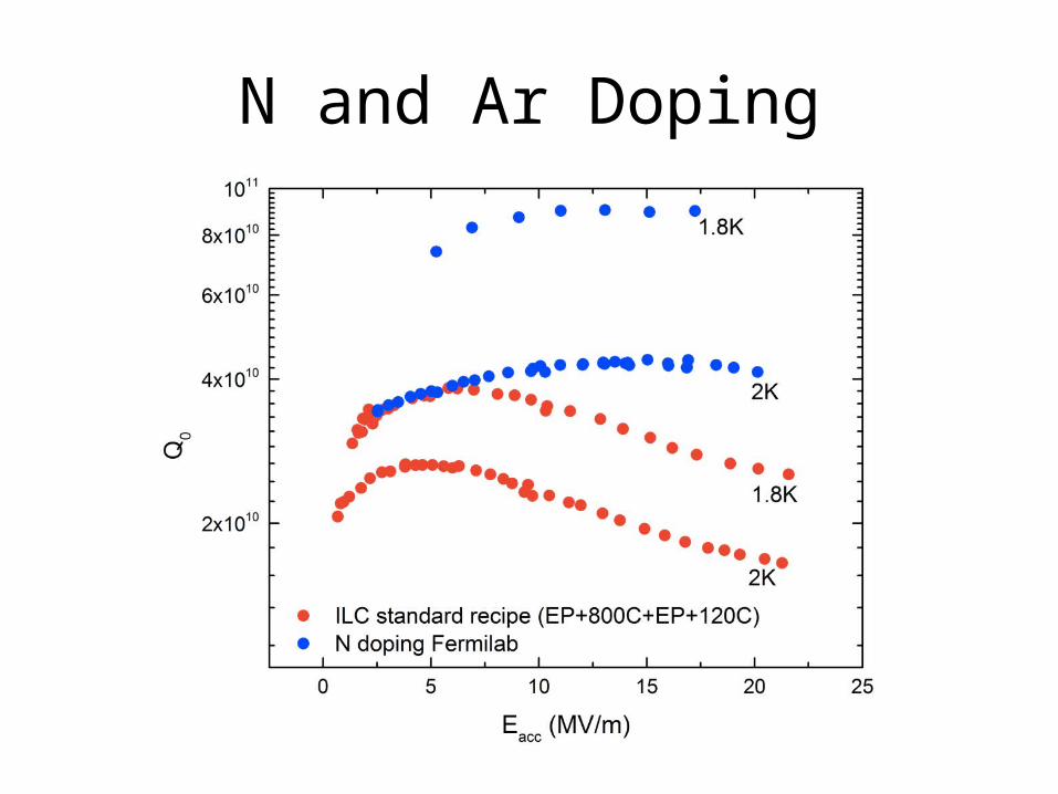
N and Ar Doping
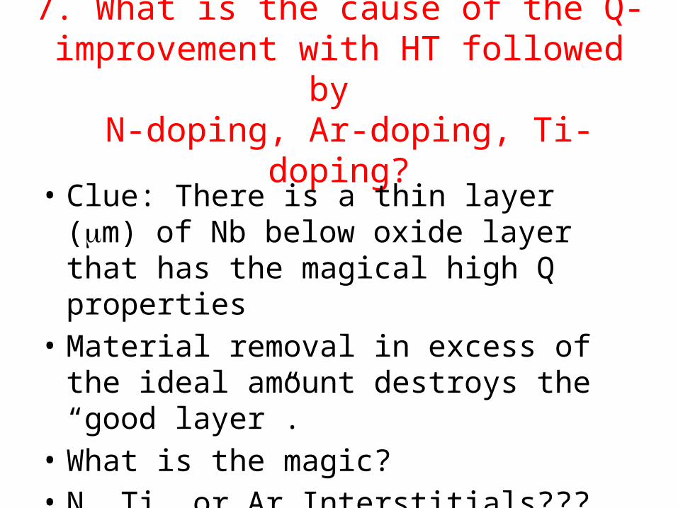
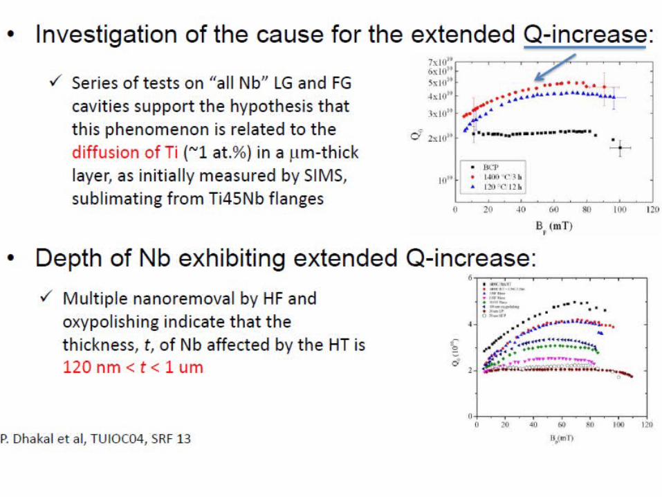
7. What is the cause of the Q-improvement with HT followed by
N-doping, Ar-doping, Ti-doping?
• Clue: There is a thin layer (mm) of Nb below oxide layer that has the magical high Q properties
• Material removal in excess of the ideal amount destroys the “good layer”.
• What is the magic?• N, Ti, or Ar Interstitials???
l
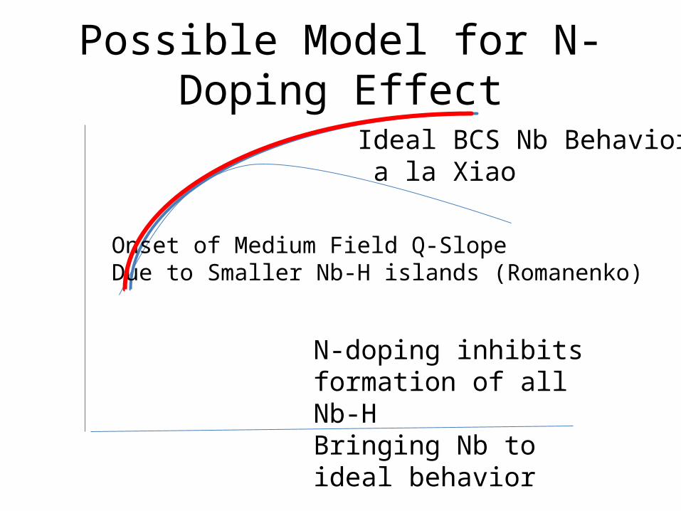
Possible Model for N-Doping Effect
Ideal BCS Nb Behavior a la Xiao
Onset of Medium Field Q-SlopeDue to Smaller Nb-H islands (Romanenko)
N-doping inhibits formation of all Nb-HBringing Nb to ideal behavior
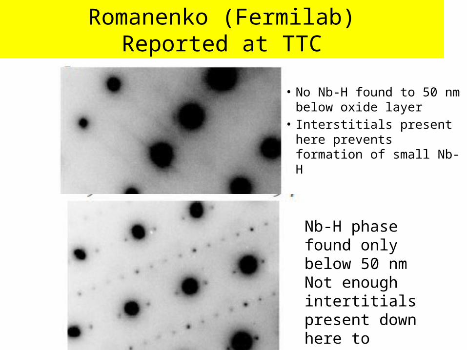
• No Nb-H found to 50 nm below oxide layer
• Interstitials present here prevents formation of small Nb-H
Romanenko (Fermilab) Reported at TTC
Nb-H phase found only below 50 nmNot enough intertitials present down here to prevent formation of Nb-H?

8. Is there any material out there which can reach higher gradients than Nb?
• What is the potential for HiTc?
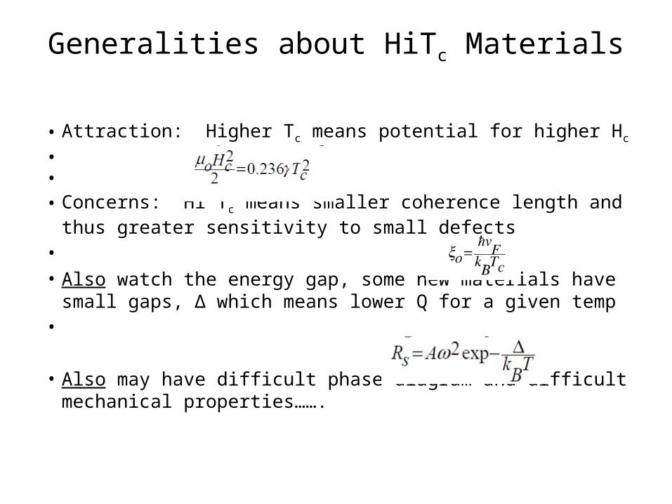
Generalities about HiTc Materials
• Attraction: Higher Tc means potential for higher Hc
•
•
• Concerns: Hi Tc means smaller coherence length and thus greater sensitivity to small defects
• • Also watch the energy gap, some new materials have small
gaps, ∆ which means lower Q for a given temp•
• Also may have difficult phase diagram and difficult mechanical properties…….
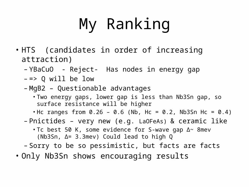
My Ranking
• HTS (candidates in order of increasing attraction)– YBaCuO - Reject- Has nodes in energy gap – => Q will be low– MgB2 – Questionable advantages
• Two energy gaps, lower gap is less than Nb3Sn gap, so surface resistance will be higher
• Hc ranges from 0.26 – 0.6 (Nb, Hc = 0.2, Nb3Sn Hc = 0.4)
– Pnictides – very new (e.g. LaOFeAs) & ceramic like• Tc best 50 K, some evidence for S-wave gap ∆~ 8mev (Nb3Sn, ∆=
3.3mev) Could lead to high Q
– Sorry to be so pessimistic, but facts are facts• Only Nb3Sn shows encouraging results
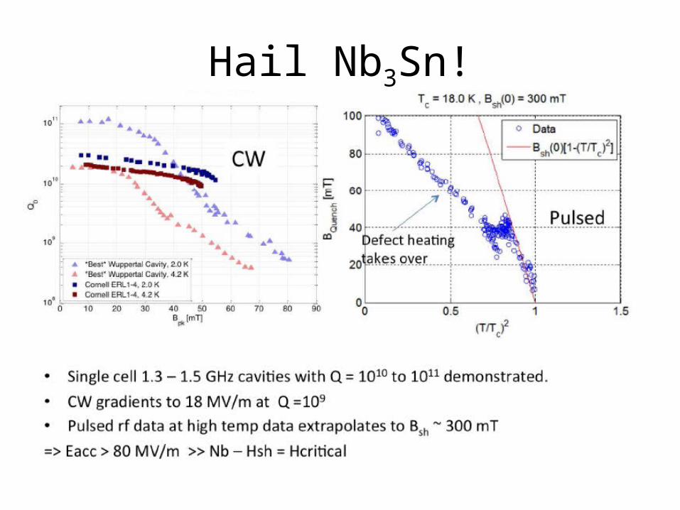
Hail Nb3Sn!

To Conclude
• With all these unanswered questions• Peter, do you still really want to retire?• Take it from a professional retiree• What did I miss the most when I retired?• So…..I wish you the best• Find something else to be passionate about• as you always have been about SRF