welch allyn eli 280...resting electrocardiograph service manual manufactured by welch allyn, inc....
TRANSCRIPT

RESTING ELECTROCARDIOGRAPH
SERVICE MANUAL
Manufactured by Welch Allyn, Inc. Skaneateles Falls, NY U.S.A.
CAUTION: Federal law restricts this device to sale by or on the order of a physician
Welch Allyn® ELI® 280

© 2019 Welch Allyn This document contains confidential information that belongs to Welch Allyn, Inc. No part of
this document may be transmitted, reproduced, used, or disclosed outside of the receiving organization without the
express written consent of Welch Allyn, Inc. Welch Allyn is a registered trademark of Welch Allyn, Inc. AM12,
ELI, VERITAS, and WAM are trademarks of Welch Allyn, Inc. DICOM is the registered trademark of the
National Electrical Manufacturers Association for its standards publications relating to digital communications
of medical information. Software V2.4.1
For patent information, please visit www.welchallyn.com/patents
For information about any Welch Allyn product, visit: https://www.welchallyn.com/en/about-us/locations.html
Customer Service and Technical Support: https://www.welchallyn.com/en/other/contact-us.html 1.888.667.8272,
9516-181-50-ENG Rev E
Revision date: 2019-09
901132 ELECTROCARDIOGRAPH
EU IMPORTER
Welch Allyn, Inc.
4341 State Street Road
Skaneateles Falls, NY 13153 USA
www.welchallyn.com
Welch Allyn Limited
Navan Business Park, Dublin Road,
Navan, Co. Meath C15 AW22
Ireland
1
TABLE OF CONTENTS
NOTICES ................................................................................................................................................................. 3
MANUFACTURER’S RESPONSIBILITY .................................................................................................................................... 3 RESPONSIBILITY OF THE CUSTOMER .................................................................................................................................... 3 EQUIPMENT IDENTIFICATION ............................................................................................................................................. 3 COPYRIGHT AND TRADEMARK NOTICES ............................................................................................................................... 3 OTHER IMPORTANT INFORMATION ..................................................................................................................................... 3
WARRANTY INFORMATION ................................................................................................................................... 4
YOUR WELCH ALLYN WARRANTY ....................................................................................................................................... 4
USER SAFETY INFORMATION ................................................................................................................................. 5
WARNING(S) ............................................................................................................................................................. 5 CAUTION(S) ................................................................................................................................................................. 7 NOTE(S) ....................................................................................................................................................................... 8
EQUIPMENT SYMBOLS AND MARKINGS .............................................................................................................. 11
SYMBOL DELINEATION ................................................................................................................................................... 11
SYSTEM SETTINGS ................................................................................................................................................ 13
PRECAUTIONS .............................................................................................................................................................. 13 INSPECTION ................................................................................................................................................................. 13 CLEANING EXTERIOR SURFACES AND PATIENT ACQUISITION DEVICE ........................................................................................ 13
ELECTROMAGNETIC COMPATIBILITY (EMC) ......................................................................................................... 14
SYSTEM SETTINGS ................................................................................................................................................ 18
MENU COMMANDS AND UTILITIES ................................................................................................................................... 19 SECURITY .................................................................................................................................................................... 21 CONFIGURATION SETTINGS: ABOUT ................................................................................................................................ 22 CONFIGURATION SETTINGS: MODEM .............................................................................................................................. 23 CONFIGURATION SETTINGS: SYSTEM ................................................................................................................................ 24 CONFIGURATION SETTINGS: ECG .................................................................................................................................... 27 CONFIGURATION SETTINGS: LAN .................................................................................................................................... 31 CONFIGURATION SETTINGS: DATE/TIME .......................................................................................................................... 34
PREVENTIVE MAINTENANCE ................................................................................................................................ 35
RECOMMENDED TOOLS AND SUPPLIES .............................................................................................................................. 35 PREVENTIVE MAINTENANCE PROCEDURE .......................................................................................................................... 36 DEVICE TESTING ........................................................................................................................................................... 37 CALIBRATION ............................................................................................................................................................... 39 DEVICE CLEANING ......................................................................................................................................................... 40 SAFETY TESTING ........................................................................................................................................................... 41 ELI 280 PREVENTIVE MAINTENANCE REPORT .................................................................................................................... 42 SEALED LEAD-ACID BATTERY PERFORMANCE INFORMATION ................................................................................................. 43
UNIT DISASSEMBLY .............................................................................................................................................. 45
BATTERY REMOVAL ....................................................................................................................................................... 46 UPPER HOUSING REMOVAL ............................................................................................................................................ 47 THERMAL WRITER REMOVAL .......................................................................................................................................... 49 MOTHERBOARD REMOVAL ............................................................................................................................................. 51
TABLE OF CONTENTS
2
ELI 280 UPPER HOUSING AND TOUCH SCREEN ASSEMBLY REMOVAL ..................................................................................... 52 TOUCH SCREEN CONTROLLER PCA REMOVAL .................................................................................................................... 53 THERMAL WRITER DISASSEMBLY ..................................................................................................................................... 59 GEARBOX AND MOTOR .................................................................................................................................................. 66 CUE SENSOR REPLACEMENT............................................................................................................................................ 67 PRINTHEAD REPLACEMENT ............................................................................................................................................. 68 ELI 280 WRITER A4/SMART PAPER SPACER ...................................................................................................................... 69 ORDER OF REASSEMBLY ................................................................................................................................................. 76
CONFORMANCE TESTING ..................................................................................................................................... 80
POWER TESTING ........................................................................................................................................................... 80 FUNCTIONAL TESTING .................................................................................................................................................... 81 ELI 280 TEST DATA RECORD .......................................................................................................................................... 85
TROUBLESHOOTING............................................................................................................................................. 86
ECG TROUBLESHOOTING CHART ..................................................................................................................................... 86 ECG ELECTRODE PLACEMENT TROUBLESHOOTING .............................................................................................................. 86 PATIENT CABLE TROUBLESHOOTING CHART ....................................................................................................................... 87 ECG TRANSMISSION TROUBLESHOOTING CHART ................................................................................................................ 88 THERNET TRANSMISSION STATUS INDICATOR LEDS ............................................................................................................. 89 DISPLAY TROUBLESHOOTING CHART ................................................................................................................................. 89 PRINTER TROUBLESHOOTING CHART ................................................................................................................................ 90
SPECIAL FUNCTIONS ............................................................................................................................................ 91
TIME SYNC .................................................................................................................................................................. 91 TESTING THE WLAN/LAN SETTINGS................................................................................................................................ 91 CUE SENSOR CALIBRATION ............................................................................................................................................. 91 AUTO TEST .................................................................................................................................................................. 91 CHANGE THE DEVICE OWNER’S NAME .............................................................................................................................. 92 COPY LOG FILES TO A USB FLASH DRIVE ........................................................................................................................... 92 COPY ALL ECG RECORDS TO A USB FLASH DRIVE ............................................................................................................... 92 ERASE ALL ECG RECORDS .............................................................................................................................................. 92 WRITER TEST ............................................................................................................................................................... 92 TEST CONFIGURATION* ................................................................................................................................................. 93 CLEAR FLAGS ............................................................................................................................................................... 93 FILL DIRECTORY ............................................................................................................................................................ 93 FIRMWARE .................................................................................................................................................................. 93 CONFIG FILE ................................................................................................................................................................ 93 OPTIONS FILE ............................................................................................................................................................... 93 FIRST TIME BOOT ......................................................................................................................................................... 94 IIR ON ........................................................................................................................................................................ 94
COMMUNICATION OPTIONS ................................................................................................................................ 95
COMMUNICATION OPTION INSTALLATION/UPGRADES ......................................................................................................... 95

3
NOTICES
Manufacturer’s Responsibility
Welch Allyn, Inc. is responsible for the effects on safety and performance only if:
• Assembly operations, extensions, readjustments, modifications, or repairs are carried out only by persons
authorized by Welch Allyn, Inc.
• The device is used in accordance with the instructions for use.
Responsibility of the Customer
The user of this device is responsible for ensuring the implementation of a satisfactory maintenance schedule.
Failure to do so may cause undue failure and possible health hazards.
Equipment Identification
Welch Allyn, Inc. equipment is identified by a serial and reference number on the bottom of the device. Care should
be taken so that these numbers are not defaced.
Copyright and Trademark Notices
This document contains information that is protected by copyright. All rights are reserved. No part of this
document may be photocopied, reproduced, or translated to another language without prior written consent of Welch
Allyn, Inc.
Other Important Information
The information in this document is subject to change without notice.
Welch Allyn, Inc. makes no warranty of any kind with regard to this material including, but not limited to, implied
warranties of merchantability and fitness for a particular purpose. Welch Allyn, Inc. assumes no responsibility for
any errors or omissions that may appear in this document. Welch Allyn Instrument, Inc. makes no commitment to
update or to keep current the information contained in this document.

4
WARRANTY INFORMATION
Your Welch Allyn Warranty
Welch Allyn, Inc. (hereafter referred to as “Welch Allyn”) warrants that components within Welch Allyn products
(hereafter referred to as “Product/s”) will be free from defects in workmanship and materials for the number of years
specified on documentation accompanying the product, or previously agreed to by the purchaser and Welch Allyn,
or if not otherwise noted, for a period of twenty-four (24) months from the date of shipment.
Consumable, disposable or single use products such as, but not limited to, PAPER or ELECTRODES are warranted
to be free from defects in workmanship and materials for a period of 90 days from the date of shipment or the date
of first use, whichever is sooner.
Reusable product such as, but not limited to, BATTERIES, BLOOD PRESSURE CUFFS, BLOOD PRESSURE
HOSES, TRANSDUCER CABLES, Y-CABLES, PATIENT CABLES, LEAD WIRES, MAGNETIC STORAGE
MEDIUMS, CARRY CASES or MOUNTS, are warranted to be free from defects in workmanship and materials for
a period of 90 days. This warranty does not apply to damage to the Product/s caused by any or all of the following
circumstances or conditions:
a) Freight damage;
b) Parts and/or accessories of the Product/s not obtained from or approved by Welch Allyn;
c) Misapplication, misuse, abuse, and/or failure to follow the Product/s instruction sheets and/or information
guides;
d) Accident; a disaster affecting the Product/s;
e) Alterations and/or modifications to the Product/s not authorized by Welch Allyn;
f) Other events outside of Welch Allyn’s reasonable control or not arising under normal operating conditions.
THE REMEDY UNDER THIS WARRANTY IS LIMITED TO THE REPAIR OR REPLACEMENT WITHOUT
CHARGE FOR LABOR OR MATERIALS, OR ANY PRODUCT/S FOUND UPON EXAMINATION BY Welch
Allyn TO HAVE BEEN DEFECTIVE. This remedy shall be conditioned upon receipt of notice by Welch Allyn of
any alleged defects promptly after discovery thereof within the warranty period. Welch Allyn’s obligations under the
foregoing warranty will further be conditioned upon the assumption by the purchaser of the Product/s (i) of all carrier
charges with respect to any Product/s returned to Welch Allyn’s principal place or any other place as specifically
designated by Welch Allyn or an authorized distributor or representative of Welch Allyn, and (ii) all risk of loss in
transit. It is expressly agreed that the liability of Welch Allyn is limited and that Welch Allyn does not function as an
insurer. A purchaser of a Product/s, by its acceptance and purchase thereof, acknowledges and agrees that Welch
Allyn is not liable for loss, harm, or damage due directly or indirectly to an occurrence or consequence therefrom
relating to the Product/s. If Welch Allyn should be found liable to anyone under any theory (except the expressed
warranty set forth herein) for loss, harm, or damage, the liability of Welch Allyn shall be limited to the lesser of the
actual loss, harm, or damage, or the original purchase price of the Product/s when sold.
EXCEPT AS SET FORTH HEREIN WITH RESPECT TO REIMBURSEMENT OF LABOR CHARGES, A
PURCHASER’S SOLE EXCLUSIVE REMEDY AGAINST WELCH ALLYN FOR CLAIMS RELATING TO THE
PRODUCT/S FOR ANY AND ALL LOSSES AND DAMAGES RESULTING FROM ANY CAUSE SHALL BE
THE REPAIR OR REPLACEMENT OF DEFECTIVE PRODUCT/S TO THE EXTENT THAT THE DEFECT IS
NOTICED AND WELCH ALLYN IS NOTIFIED WITHIN THE WARRANTY PERIOD. IN NO EVENT,
INCLUDING THE CLAIM FOR NEGLIGENCE, SHALL WELCH ALLYN BE LIABLE FOR INCIDENTAL,
SPECIAL, OR CONSEQUENTIAL DAMAGES, OR FOR ANY OTHER LOSS, DAMAGE, OR EXPENSE OF
ANY KIND, INCLUDING LOSS OF PROFITS, WHETHER UNDER TORT, NEGLIGENCE OR STRICT
LIABILITY THEORIES OF LAW, OR OTHERWISE. THIS WARRANTY IS EXPRESSLY IN LIEU OF ANY
OTHER WARRANTIES, EXPRESS OR IMPLIED, INCLUDING, BUT NOT LIMITED TO THE IMPLIED
WARRANTY OF MERCHANTABILITY AND THE WARRANTY OF FITNESS FOR A PARTICULAR
PURPOSE.
5
USER SAFETY INFORMATION
WARNING: Means there is the possibility of personal injury to you or others.
Caution: Means there is the possibility of damage to the device.
Note: Provides information to further assist in the use of the device.
NOTE: This manual may contain screen shots and pictures. Any screen shots and pictures are provided
for reference only and are not intended to convey actual operating techniques. Consult the actual screen in
the host language for specific wording.
WARNING(S)
This manual gives important information about the use and safety of this device. Deviating from operating
procedures, misuse or misapplication of the device, or ignoring specifications and recommendations could
result in increased risk of harm to users, patients and bystanders, or damage to the device.
Device captures and presents data reflecting a patient’s physiological condition that when reviewed by a trained
physician or clinician can be useful in determining a diagnosis; however, the data should not be used as a sole
means for determining a patient’s diagnosis.
Users are expected to be licensed clinical professionals knowledgeable about medical procedures and patient
care, and adequately trained in the use of this device. Before attempting to use this device for clinical
applications, the operator must read and understand the contents of the user manual and other accompanying
documents. Inadequate knowledge or training could result in increased risk of harm to users, patients and
bystanders, or damage to the device. Contact Welch Allyn service for additional training options.
To ensure that electrical safety is maintained during operation from AC (~) power, the device must be plugged
into a hospital-grade outlet.
To maintain designed operator and patient safety, peripheral equipment and accessories used that can come in
direct patient contact must be in compliance with UL 60601-1, IEC 60601-1, and IEC 60601-2-25. Only use
parts and accessories supplied with the device and available through Welch Allyn, Inc.
Patient acquisition devices intended for use with the device include series resistance (9 Kohm minimum) in
each lead for defibrillation protection. Patient acquisition devices should be checked for cracks or breakage
prior to use.
Conductive parts of the Patient acquisition device, electrodes, and associated connections of type CF applied
parts, including the neutral conductor of the Patient acquisition device and electrodes, should not come into
contact with other conductive parts including earth ground.
ECG electrodes could cause skin irritation; patients should be examined for signs of irritation or inflammation.
To avoid the possibility of serious injury or death during patient defibrillation, do not come into contact with
device or Patient acquisition devices. Additionally, proper placement of defibrillator paddles in relation to the
electrodes is required to minimize harm to the patient.

USER SAFETY INFORMATION
6
This device does not automatically switch between direct or wireless Patient acquisition devices. Clinician
must choose Patient acquisition device before ECG acquisition. If your device is equipped with a receiver for a
wireless Patient acquisition device, always make sure that you are receiving data from the expected module.
This device was designed to use the electrodes specified in the user manual. Proper clinical procedure must be
employed to prep the electrode sites and to monitor the patient for excessive skin irritation, inflammation, or
other adverse reactions. Electrodes are intended for short-term use and should be removed from the patient
promptly following testing.
To avoid potential for spread of disease or infection, single-use disposable components (e.g., electrodes) must
not be reused. To maintain safety and effectiveness, electrodes must not be used beyond their expiration date.
To ensure the safety of both the patient and the device, 1.5 meters (5 feet) of open area should surround the
patient.
A possible explosion hazard exists. Do not use the device in the presence of a flammable anesthetic mixture.
Where the integrity of external protective earth conductor arrangement is in doubt, the device shall be operated
from its internal electrical power source.
All signal input and output (I/O) connectors are intended for connection of only those devices complying with
IEC 60601-1, or other IEC standards (e.g., IEC 60950) as appropriate to the device. Connecting additional
devices to the device may increase chassis and/or patient leakage currents. To maintain operator and patient
safety, consideration should be given to the requirements of IEC 60601-1-1, and leakage currents should be
measured to confirm no electric shock hazard exists.
To improve immunity to potential interfering electromagnetic signals, shielded cabling is recommended when
connecting the device to a network.
To maintain operator and patient safety, equipment connected to the same network as the device must meet the
requirements of IEC 60950 or IEC 60601-1.
To prevent electric shock due to unequal ground potentials that may exist between points of a distributed
network system or fault conditions in external network connected equipment, network cable shielding (where
used) must be connected to protective earth ground appropriate to the area where the device is used.
The device has not been designed for use with high-frequency (HF) surgical equipment and does not provide a
protective means against hazards to the patient.
The quality of the signal produced by the device may be adversely affected by the use of other medical
equipment, including but not limited to defibrillators and ultrasound machines.
For proper operation and the safety of users or patients and bystanders, equipment and accessories must be
connected only as described in this manual. Do not connect a telephone line cable to the LAN connector.

USER SAFETY INFORMATION
7
Some Welch Allyn electrocardiographs can be equipped with a GPRS (cellular modem) or wireless LAN
(WLAN) module for transmitting ECG records. Device labeling and the presence of an antenna port will
indicate if your device is equipped with such a module. If so equipped, the following notices apply:
The WLAN identification can be found on a label on the bottom of the device.
Quatech, Inc. Model WLNG-AN-MR551: 2400 MHz
(model subject to change without notice)
Use of the WLAN module may interfere with other equipment operating in the vicinity. Check with local
authorities or spectrum management officials in your facility to determine if restrictions apply to the use of this
feature in your area.
● Do not transmit via the WLAN module with a missing or damaged antenna. Replace a damaged antenna
immediately.
Use only the antenna supplied for use with this device. Unauthorized antennas, modifications, or attachments
could damage the WLAN module and may contravene local RF emission regulations or invalidate type
approval.
To ensure compliance with current regulations limiting both maximum RF output power and human exposure
to radio frequency radiation, a separation distance of at least 20 cm must be maintained between the device's
antenna and the head and body of the user and any nearby persons at all times. To help prevent degradation of
RF signal and to avoid excess RF energy absorption, do not touch the antenna during data transmission.
The WLAN module complies with applicable RF safety standards including standards and recommendations
for the protection of public exposure to RF electromagnetic energy that have been established by governmental
bodies and other qualified organizations, such as the following:
Federal Communications Commission (FCC)
Directives of the European Community
Directorate General V in Matters of Radio Frequency Electromagnetic Energy
Caution(s)
To prevent possible damage to the touchscreen, do not use sharp objects to touch the screen icons, only use
fingertips.
Do not attempt to clean the device or patient acquisition device by submersing into a liquid, autoclaving, or
steam cleaning as this may damage equipment or reduce its usable life. Wipe the exterior surfaces with a warm
water and mild detergent solution and then dry with a clean cloth. Use of unspecified cleaning/disinfecting
agents, failure to follow recommended procedures, or contact with unspecified materials could result in
increased risk of harm to users, patients and bystanders, or damage to the device.
No user-serviceable parts inside. Screw removal by qualified service personnel only. Damaged or suspected
inoperative equipment must be immediately removed from use and must be checked/repaired by qualified
service personnel prior to continued use.
The rechargeable internal battery is a sealed lead-acid type and it is totally maintenance free. If the battery
appears to become defective, refer to Welch Allyn Service Department.
Do not pull or stretch patient acquisition device as this could result in mechanical and/or electrical failures.
Patient cables should be stored after forming them into a loose loop.

USER SAFETY INFORMATION
8
Calibration of the display is required before initial operation of the unit. No special equipment is needed for the
proper operation or maintenance of the device.
When necessary, dispose of the device, its components and accessories (e.g., batteries, cables, electrodes),
and/or packing materials in accordance with local regulations.
Proper functioning backup items such as a spare patient cable, front-end device, display monitor, and other
equipment are recommended on hand to prevent delayed treatment due to an inoperable device.
Note(s)
Patient movement may generate excessive noise that may affect the quality of the ECG traces and the proper
analysis performed by the device.
Proper patient preparation is important to proper application of ECG electrodes and operation of the device.
The algorithm detecting electrode misplacements is based on normal physiology and ECG lead order, and tries
to identify the most likely switch; however, it is advisable to check the other electrode positions in the same
group (limb or chest).
There is no known safety hazard if other equipment, such as pacemakers or other stimulators, is used
simultaneously with the device; however, disturbance to the signal may occur.
If a thick baseline is presented on the display while using the WAM (square waves on rhythm printout), this
may be due to the WAM being turned off, has no battery, is out of range or has experienced a calibration error.
Review the LED indicator on the WAM to assure the unit is turned on, has proper battery level, assure the
WAM is paired correctly and is within recommended proximity of the electrocardiograph or power cycle the
WAM to re-calibrate. Review the WAM user manual for details.
If a thick baseline is presented on the display while using the AM12 (square waves on rhythm printout), this
may be due to an improper auto-calibration. Reconnect the AM12 or power cycle the electrocardiograph.
If a square wave is presented on the display and rhythm printout this may be due to the WAM, AM12 or some
lead wires not being connected to a patient.
As defined by IEC 60601-1 and IEC 60601-2-25, the device is classified as follows:
Class I equipment or internally powered.
Type CF defibrillation-proof applied parts.
Ordinary equipment.
Equipment not suitable for use in the presence of a flammable anesthetic mixture.
Continuous operation.
NOTE: From a safety perspective, per IEC 60601-1 and derivative standards/norms, this device is
declared to be “Class I” and uses a three-prong inlet to ensure an earth connection is made along with
mains. The ground terminal on the mains inlet is the only protective earth point in the device. Exposed
metal accessible during normal operation is double insulated from mains. Internal connections to earth
ground are functional earth.
USER SAFETY INFORMATION
9
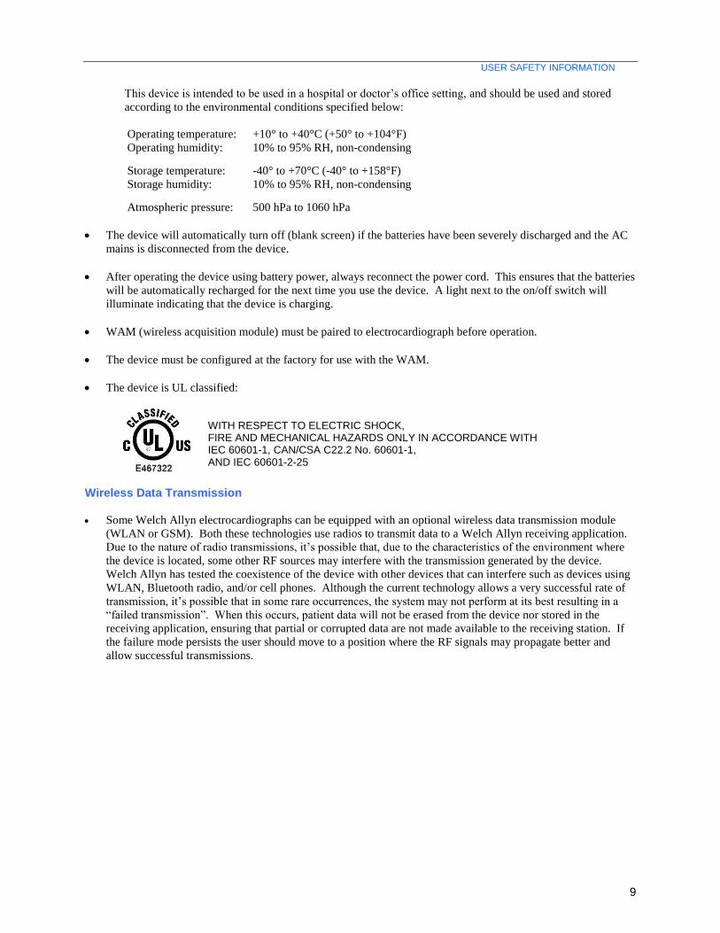
This device is intended to be used in a hospital or doctor’s office setting, and should be used and stored
according to the environmental conditions specified below:
Operating temperature: +10° to +40°C (+50° to +104°F)
Operating humidity: 10% to 95% RH, non-condensing
Storage temperature: -40° to +70°C (-40° to +158°F)
Storage humidity: 10% to 95% RH, non-condensing
Atmospheric pressure: 500 hPa to 1060 hPa
The device will automatically turn off (blank screen) if the batteries have been severely discharged and the AC
mains is disconnected from the device.
After operating the device using battery power, always reconnect the power cord. This ensures that the batteries
will be automatically recharged for the next time you use the device. A light next to the on/off switch will
illuminate indicating that the device is charging.
WAM (wireless acquisition module) must be paired to electrocardiograph before operation.
The device must be configured at the factory for use with the WAM.
The device is UL classified:
WITH RESPECT TO ELECTRIC SHOCK, FIRE AND MECHANICAL HAZARDS ONLY IN ACCORDANCE WITH IEC 60601-1, CAN/CSA C22.2 No. 60601-1, AND IEC 60601-2-25
Wireless Data Transmission
Some Welch Allyn electrocardiographs can be equipped with an optional wireless data transmission module
(WLAN or GSM). Both these technologies use radios to transmit data to a Welch Allyn receiving application.
Due to the nature of radio transmissions, it’s possible that, due to the characteristics of the environment where
the device is located, some other RF sources may interfere with the transmission generated by the device.
Welch Allyn has tested the coexistence of the device with other devices that can interfere such as devices using
WLAN, Bluetooth radio, and/or cell phones. Although the current technology allows a very successful rate of
transmission, it’s possible that in some rare occurrences, the system may not perform at its best resulting in a
“failed transmission”. When this occurs, patient data will not be erased from the device nor stored in the
receiving application, ensuring that partial or corrupted data are not made available to the receiving station. If
the failure mode persists the user should move to a position where the RF signals may propagate better and
allow successful transmissions.
USER SAFETY INFORMATION
10
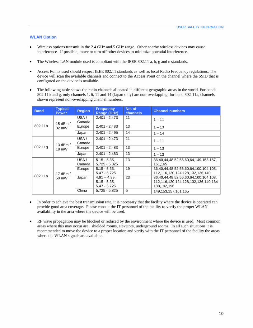
WLAN Option
Wireless options transmit in the 2.4 GHz and 5 GHz range. Other nearby wireless devices may cause
interference. If possible, move or turn off other devices to minimize potential interference.
The Wireless LAN module used is compliant with the IEEE 802.11 a, b, g and n standards.
Access Points used should respect IEEE 802.11 standards as well as local Radio Frequency regulations. The
device will scan the available channels and connect to the Access Point on the channel where the SSID that is
configured on the device is available.
The following table shows the radio channels allocated in different geographic areas in the world. For bands
802.11b and g, only channels 1, 6, 11 and 14 (Japan only) are non-overlapping; for band 802-11a, channels
shown represent non-overlapping channel numbers.
Band Typical Power
Region Frequency Range (GHz)
No. of channels
Channel numbers
802.11b 15 dBm / 32 mW
USA / Canada
2.401 - 2.473 11 1 – 11
Europe 2.401 - 2.483 13 1 – 13
Japan 2.401 - 2.495 14 1 – 14
802.11g 13 dBm / 18 mW
USA / Canada
2.401 - 2.473 11 1 – 11
Europe 2.401 - 2.483 13 1 – 13
Japan 2.401 - 2.483 13 1 – 13
802.11a 17 dBm / 50 mW
USA / Canada
5.15 - 5.35, 5.725 - 5.825
13 36,40,44,48,52,56,60,64,149,153,157,161,165
Europe 5.15 - 5.35, 5.47 - 5.725
19 36,40,44,48,52,56,60,64,100,104,108,112,116,120,124,128,132,136,140
Japan 4.91 – 4.99, 5.15 - 5.35, 5.47 - 5.725
23 36,40,44,48,52,56,60,64,100,104,108,112,116,120,124,128,132,136,140,184188,192,196
China 5.725 - 5.825 5 149,153,157,161,165
In order to achieve the best transmission rate, it is necessary that the facility where the device is operated can
provide good area coverage. Please consult the IT personnel of the facility to verify the proper WLAN
availability in the area where the device will be used.
RF wave propagation may be blocked or reduced by the environment where the device is used. Most common
areas where this may occur are: shielded rooms, elevators, underground rooms. In all such situations it is
recommended to move the device to a proper location and verify with the IT personnel of the facility the areas
where the WLAN signals are available.
11
EQUIPMENT SYMBOLS AND MARKINGS
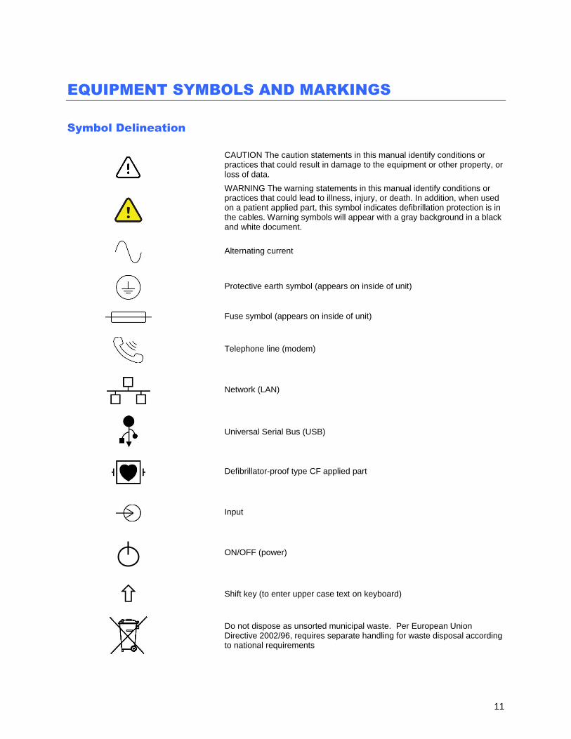
Symbol Delineation
CAUTION The caution statements in this manual identify conditions or practices that could result in damage to the equipment or other property, or loss of data.
WARNING The warning statements in this manual identify conditions or practices that could lead to illness, injury, or death. In addition, when used on a patient applied part, this symbol indicates defibrillation protection is in the cables. Warning symbols will appear with a gray background in a black and white document.
Alternating current
Protective earth symbol (appears on inside of unit)
Fuse symbol (appears on inside of unit)
Telephone line (modem)
Network (LAN)
Universal Serial Bus (USB)
Defibrillator-proof type CF applied part
Input
ON/OFF (power)
Shift key (to enter upper case text on keyboard)
Do not dispose as unsorted municipal waste. Per European Union Directive 2002/96, requires separate handling for waste disposal according to national requirements
EQUIPMENT SYMBOLS AND MARKINGS
12
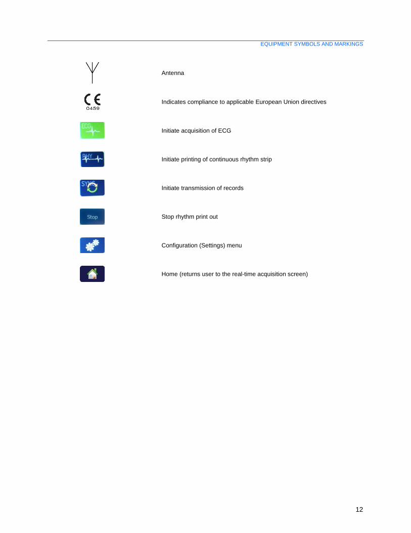
Antenna
Indicates compliance to applicable European Union directives
Initiate acquisition of ECG
Initiate printing of continuous rhythm strip
Initiate transmission of records
Stop rhythm print out
Configuration (Settings) menu
Home (returns user to the real-time acquisition screen)
13
SYSTEM SETTINGS
Precautions
Turn off the device before inspecting or cleaning.
Do not immerse the device in water.
Do not use organic solvents, ammonia-based solutions, or abrasive cleaning agents which may damage
equipment surfaces.
Inspection
Inspect your equipment daily prior to operation. If you notice anything that requires repair, contact an authorized
service person to make the repairs.
Verify that all cords and connectors are securely seated.
Check the case and chassis for any visible damage.
Inspect cords and connectors for any visible damage.
Inspect keys and controls for proper function and appearance.
Cleaning Exterior Surfaces and Patient Acquisition Device
1. Remove cables and lead wires from device before cleaning. Disconnect the power source.
2. For general cleaning of device, display, cables and lead wires, use a soft, lint-free cloth
lightly moistened with a mild soap and water solution. Wipe and air dry.
3. For disinfecting the device, wipe exterior with a soft, lint-free cloth using a solution of Sodium
Hypochlorite (10% household bleach and water solution) minimum 1:500 dilution (minimum 100
ppm free chlorine) and maximum 1:10 dilution, or a 3% hydrogen peroxide solution.
4. For disinfecting the cables and lead wires, wipe exterior with a soft, lint-free cloth using the
same solutions as for the device, or use highly concentrated (> 70%) isopropanol or ethanol.
5. Use caution with excess liquid as contact with metal parts may cause corrosion.
6. Do not immerse cable ends or lead wires; immersion can cause metal corrosion.
7. Do not use excessive drying techniques such as forced heat.
WARNING: Prevent liquid from penetrating the device and do not attempt to
clean/disinfect the device or patient cables by submerging into a liquid, autoclaving, or steam
cleaning. Never expose cables to strong ultra-violet radiation. Do not sterilize the device or ECG
lead wires with Ethylene Oxide (EtO) gas.
WARNING: Use of unspecified cleaning/disinfecting agents or failure to follow
recommended procedures could result in increased risk of harm to users, patients and bystanders,
or damage to the device.
NOTE: Welch Allyn does not endorse any specific off-the-shelf wipes or liquids. However, products that
only contain the disinfecting agents mentioned above are likely to be compatible with the device. Some
products contain a mixture of agents and may have a detrimental effect if used intensively and frequently.
Check the Material Safety Data Sheet of the product used for the list of ingredients.

14
ELECTROMAGNETIC COMPATIBILITY (EMC)
Electromagnetic compatibility with surrounding devices should be assessed when using the device.
An electronic device can either generate or receive electromagnetic interference. Testing for electromagnetic
compatibility (EMC) has been performed on the device according to the international standard for EMC for medical
devices (IEC 60601-1-2). This IEC standard has been adopted in Europe as the European Norm (EN 60601-1-2).
The device should not be used adjacent to, or stacked on top of other equipment. If the device must be used adjacent
to or stacked on top of other equipment, verify that the device operates in an acceptable manner in the configuration
in which it will be used.
Fixed, portable, and mobile radio frequency communications equipment can affect the performance of medical
equipment. See the appropriate EMC table for recommended separation distances between the radio equipment and
the device.
The use of accessories, transducers, and cables other than those specified by Welch Allyn may result in increased
emissions or decreased immunity of the equipment.
ELECTROMAGNETIC COMPATIBILITY (EMC)
15
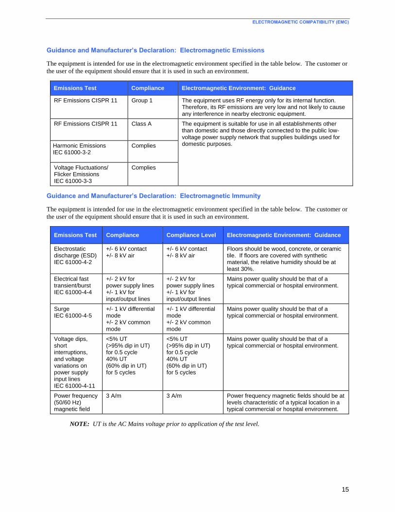
Guidance and Manufacturer’s Declaration: Electromagnetic Emissions
The equipment is intended for use in the electromagnetic environment specified in the table below. The customer or
the user of the equipment should ensure that it is used in such an environment.
Emissions Test Compliance Electromagnetic Environment: Guidance
RF Emissions CISPR 11 Group 1 The equipment uses RF energy only for its internal function. Therefore, its RF emissions are very low and not likely to cause any interference in nearby electronic equipment.
RF Emissions CISPR 11 Class A The equipment is suitable for use in all establishments other than domestic and those directly connected to the public low-voltage power supply network that supplies buildings used for domestic purposes. Harmonic Emissions
IEC 61000-3-2 Complies
Voltage Fluctuations/ Flicker Emissions IEC 61000-3-3
Complies
Guidance and Manufacturer’s Declaration: Electromagnetic Immunity
The equipment is intended for use in the electromagnetic environment specified in the table below. The customer or
the user of the equipment should ensure that it is used in such an environment.
Emissions Test Compliance Compliance Level Electromagnetic Environment: Guidance
Electrostatic discharge (ESD) IEC 61000-4-2
+/- 6 kV contact +/- 8 kV air
+/- 6 kV contact +/- 8 kV air
Floors should be wood, concrete, or ceramic tile. If floors are covered with synthetic material, the relative humidity should be at least 30%.
Electrical fast transient/burst IEC 61000-4-4
+/- 2 kV for power supply lines +/- 1 kV for input/output lines
+/- 2 kV for power supply lines +/- 1 kV for input/output lines
Mains power quality should be that of a typical commercial or hospital environment.
Surge IEC 61000-4-5
+/- 1 kV differential mode +/- 2 kV common mode
+/- 1 kV differential mode +/- 2 kV common mode
Mains power quality should be that of a typical commercial or hospital environment.
Voltage dips, short interruptions, and voltage variations on power supply input lines IEC 61000-4-11
<5% UT (>95% dip in UT) for 0.5 cycle 40% UT (60% dip in UT) for 5 cycles
<5% UT (>95% dip in UT) for 0.5 cycle 40% UT (60% dip in UT) for 5 cycles
Mains power quality should be that of a typical commercial or hospital environment.
Power frequency (50/60 Hz) magnetic field
3 A/m 3 A/m Power frequency magnetic fields should be at levels characteristic of a typical location in a typical commercial or hospital environment.
NOTE: UT is the AC Mains voltage prior to application of the test level.
ELECTROMAGNETIC COMPATIBILITY (EMC)
16
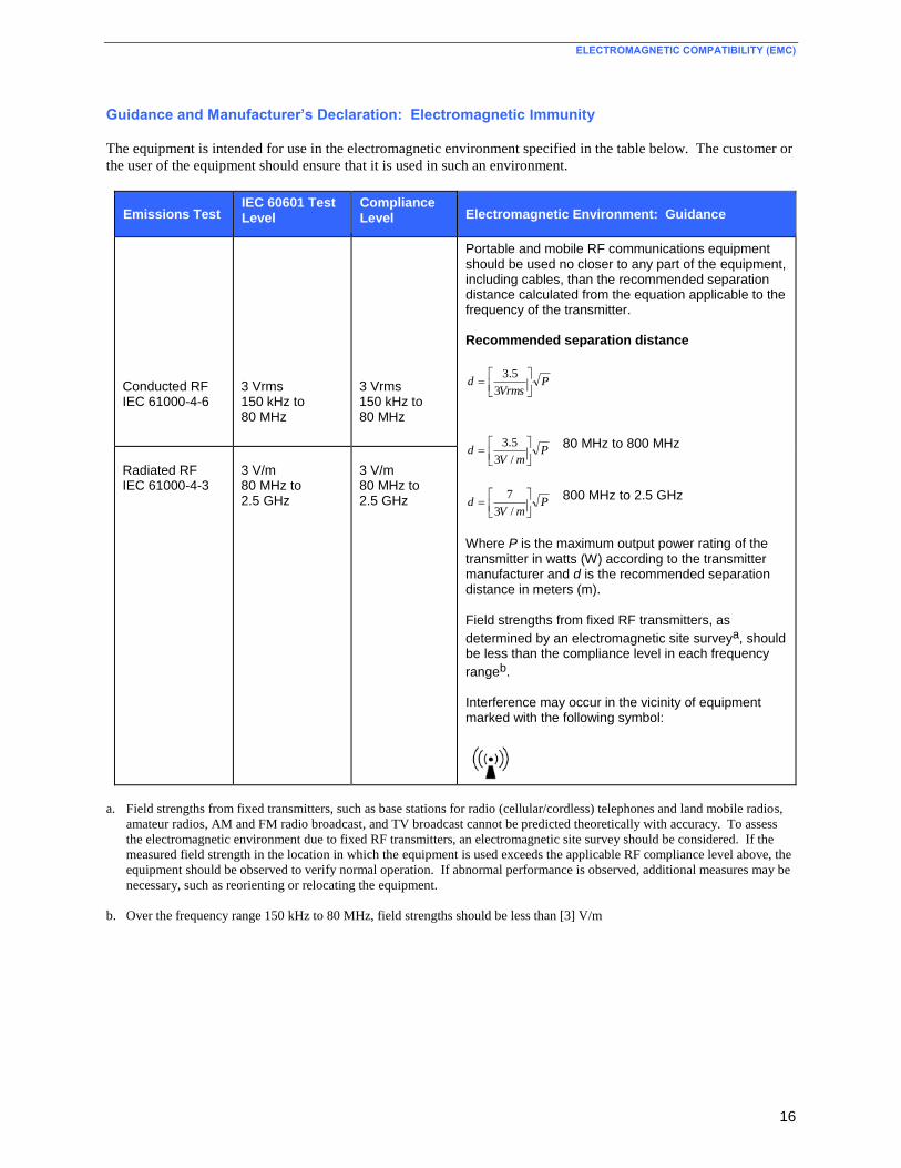
Guidance and Manufacturer’s Declaration: Electromagnetic Immunity
The equipment is intended for use in the electromagnetic environment specified in the table below. The customer or
the user of the equipment should ensure that it is used in such an environment.
Emissions Test IEC 60601 Test Level
Compliance Level Electromagnetic Environment: Guidance
Conducted RF IEC 61000-4-6
3 Vrms 150 kHz to 80 MHz
3 Vrms 150 kHz to 80 MHz
Portable and mobile RF communications equipment should be used no closer to any part of the equipment, including cables, than the recommended separation distance calculated from the equation applicable to the frequency of the transmitter.
Recommended separation distance
PVrms
d
3
5.3
PmV
d
/3
5.3 80 MHz to 800 MHz
PmV
d
/3
7 800 MHz to 2.5 GHz
Where P is the maximum output power rating of the
transmitter in watts (W) according to the transmitter manufacturer and d is the recommended separation distance in meters (m). Field strengths from fixed RF transmitters, as
determined by an electromagnetic site surveya, should be less than the compliance level in each frequency
rangeb. Interference may occur in the vicinity of equipment marked with the following symbol:
Radiated RF IEC 61000-4-3
3 V/m 80 MHz to 2.5 GHz
3 V/m 80 MHz to 2.5 GHz
a. Field strengths from fixed transmitters, such as base stations for radio (cellular/cordless) telephones and land mobile radios,
amateur radios, AM and FM radio broadcast, and TV broadcast cannot be predicted theoretically with accuracy. To assess
the electromagnetic environment due to fixed RF transmitters, an electromagnetic site survey should be considered. If the
measured field strength in the location in which the equipment is used exceeds the applicable RF compliance level above, the
equipment should be observed to verify normal operation. If abnormal performance is observed, additional measures may be
necessary, such as reorienting or relocating the equipment.
b. Over the frequency range 150 kHz to 80 MHz, field strengths should be less than [3] V/m
ELECTROMAGNETIC COMPATIBILITY (EMC)
17
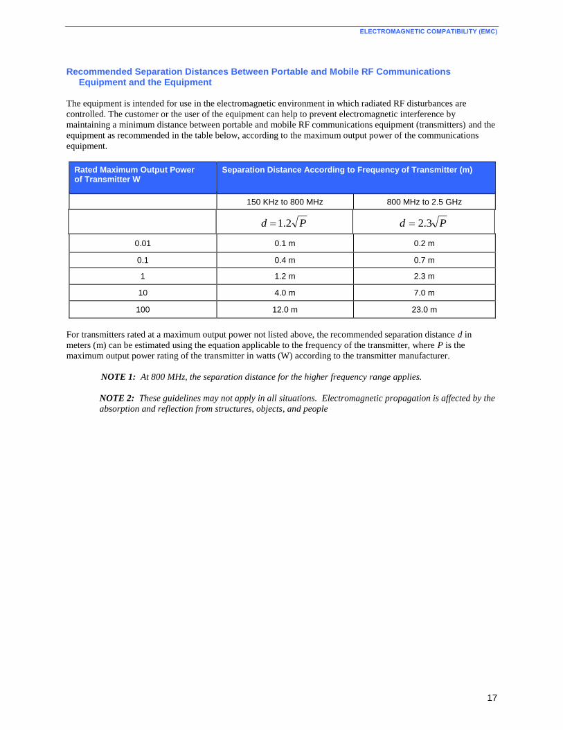
Recommended Separation Distances Between Portable and Mobile RF Communications Equipment and the Equipment
The equipment is intended for use in the electromagnetic environment in which radiated RF disturbances are
controlled. The customer or the user of the equipment can help to prevent electromagnetic interference by
maintaining a minimum distance between portable and mobile RF communications equipment (transmitters) and the
equipment as recommended in the table below, according to the maximum output power of the communications
equipment.
Rated Maximum Output Power of Transmitter W
Separation Distance According to Frequency of Transmitter (m)
150 KHz to 800 MHz 800 MHz to 2.5 GHz
Pd 2.1 Pd 3.2
0.01 0.1 m 0.2 m
0.1 0.4 m 0.7 m
1 1.2 m 2.3 m
10 4.0 m 7.0 m
100 12.0 m 23.0 m
For transmitters rated at a maximum output power not listed above, the recommended separation distance d in
meters (m) can be estimated using the equation applicable to the frequency of the transmitter, where P is the
maximum output power rating of the transmitter in watts (W) according to the transmitter manufacturer.
NOTE 1: At 800 MHz, the separation distance for the higher frequency range applies.
NOTE 2: These guidelines may not apply in all situations. Electromagnetic propagation is affected by the
absorption and reflection from structures, objects, and people
18
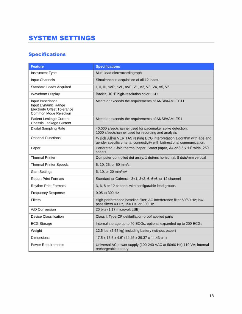
SYSTEM SETTINGS
Specifications
Feature Specifications
Instrument Type Multi-lead electrocardiograph
Input Channels Simultaneous acquisition of all 12 leads
Standard Leads Acquired I, II, III, aVR, aVL, aVF, V1, V2, V3, V4, V5, V6
Waveform Display Backlit, 10.1” high-resolution color LCD
Input Impedance Input Dynamic Range Electrode Offset Tolerance Common Mode Rejection
Meets or exceeds the requirements of ANSI/AAMI EC11
Patient Leakage Current Chassis Leakage Current
Meets or exceeds the requirements of ANSI/AAMI ES1
Digital Sampling Rate 40,000 s/sec/channel used for pacemaker spike detection; 1000 s/sec/channel used for recording and analysis
Optional Functions Welch Allyn VERITAS resting ECG interpretation algorithm with age and
gender specific criteria; connectivity with bidirectional communication;
Paper Perforated Z-fold thermal paper, Smart paper, A4 or 8.5 x 11” wide, 250 sheets
Thermal Printer Computer-controlled dot array; 1 dot/ms horizontal, 8 dots/mm vertical
Thermal Printer Speeds 5, 10, 25, or 50 mm/s
Gain Settings 5, 10, or 20 mm/mV
Report Print Formats Standard or Cabrera: 3+1, 3+3, 6, 6+6, or 12 channel
Rhythm Print Formats 3, 6, 8 or 12 channel with configurable lead groups
Frequency Response 0.05 to 300 Hz
Filters High-performance baseline filter; AC interference filter 50/60 Hz; low-pass filters 40 Hz, 150 Hz, or 300 Hz
A/D Conversion 20 bits (1.17 microvolt LSB)
Device Classification Class I, Type CF defibrillation-proof applied parts
ECG Storage Internal storage up to 40 ECGs; optional expanded up to 200 ECGs
Weight 12.5 lbs. (5.68 kg) including battery (without paper)
Dimensions 17.5 x 15.5 x 4.5” (44.45 x 39.37 x 11.43 cm)
Power Requirements Universal AC power supply (100-240 VAC at 50/60 Hz) 110 VA; internal rechargeable battery
SYSTEM SETTINGS
19
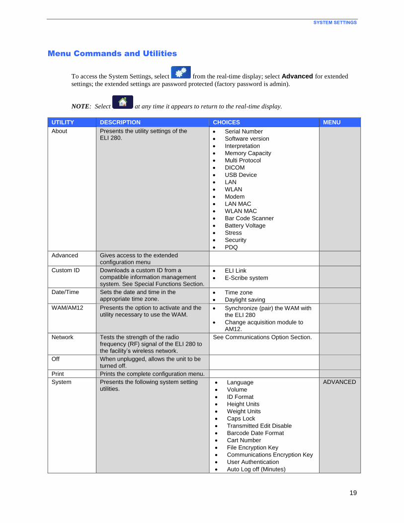
Menu Commands and Utilities
To access the System Settings, select from the real-time display; select Advanced for extended
settings; the extended settings are password protected (factory password is admin).
NOTE: Select at any time it appears to return to the real-time display.
UTILITY DESCRIPTION CHOICES MENU
About Presents the utility settings of the ELI 280.
Serial Number
Software version
Interpretation
Memory Capacity
Multi Protocol
DICOM
USB Device
LAN
WLAN
Modem
LAN MAC
WLAN MAC
Bar Code Scanner
Battery Voltage
Stress
Security
PDQ
Advanced Gives access to the extended configuration menu
Custom ID Downloads a custom ID from a compatible information management system. See Special Functions Section.
ELI Link
E-Scribe system
Date/Time Sets the date and time in the appropriate time zone.
Time zone
Daylight saving
WAM/AM12 Presents the option to activate and the utility necessary to use the WAM.
Synchronize (pair) the WAM with the ELI 280
Change acquisition module to AM12.
Network Tests the strength of the radio frequency (RF) signal of the ELI 280 to the facility’s wireless network.
See Communications Option Section.
Off When unplugged, allows the unit to be turned off.
Print Prints the complete configuration menu.
System Presents the following system setting utilities.
Language
Volume
ID Format
Height Units
Weight Units
Caps Lock
Transmitted Edit Disable
Barcode Date Format
Cart Number
File Encryption Key
Communications Encryption Key
User Authentication
Auto Log off (Minutes)
ADVANCED
SYSTEM SETTINGS
20
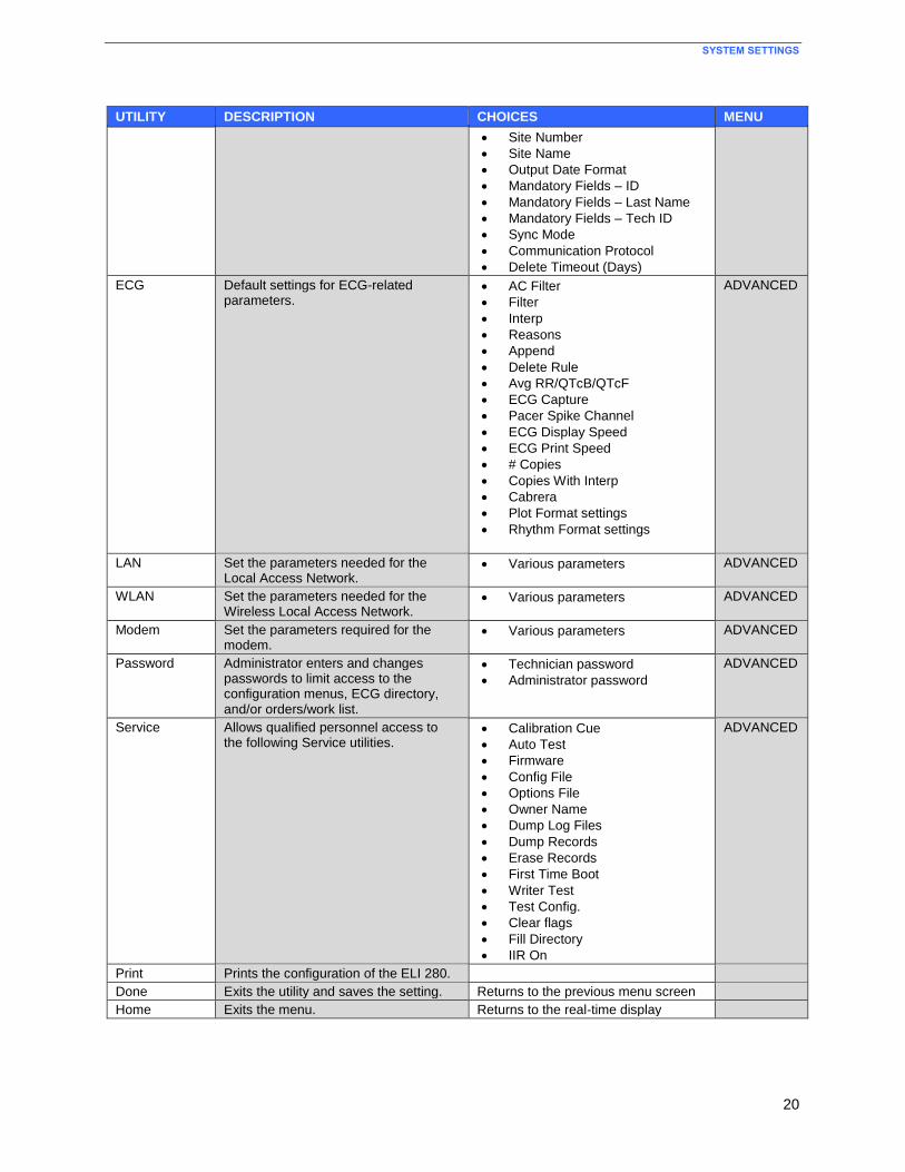
UTILITY DESCRIPTION CHOICES MENU
Site Number
Site Name
Output Date Format
Mandatory Fields – ID
Mandatory Fields – Last Name
Mandatory Fields – Tech ID
Sync Mode
Communication Protocol
Delete Timeout (Days)
ECG Default settings for ECG-related parameters.
AC Filter
Filter
Interp
Reasons
Append
Delete Rule
Avg RR/QTcB/QTcF
ECG Capture
Pacer Spike Channel
ECG Display Speed
ECG Print Speed
# Copies
Copies With Interp
Cabrera
Plot Format settings
Rhythm Format settings
ADVANCED
LAN Set the parameters needed for the Local Access Network.
Various parameters ADVANCED
WLAN Set the parameters needed for the Wireless Local Access Network.
Various parameters ADVANCED
Modem Set the parameters required for the modem.
Various parameters ADVANCED
Password Administrator enters and changes passwords to limit access to the configuration menus, ECG directory, and/or orders/work list.
Technician password
Administrator password
ADVANCED
Service Allows qualified personnel access to the following Service utilities.
Calibration Cue
Auto Test
Firmware
Config File
Options File
Owner Name
Dump Log Files
Dump Records
Erase Records
First Time Boot
Writer Test
Test Config.
Clear flags
Fill Directory
IIR On
ADVANCED
Print Prints the configuration of the ELI 280.
Done Exits the utility and saves the setting. Returns to the previous menu screen
Home Exits the menu. Returns to the real-time display
SYSTEM SETTINGS
21
Security
The Administrator password controls several functions and should be created and secured with care. Log the
Administrator password in a location where it can be accessed during an emergency and in a backup location so it
can be accessed if the primary location is compromised. The ELI 280 is preset with the case-sensitive Administrator
password “admin.” To change the Administrator password, see Setting Passwords.
The Administrator password enables:
a. Access to the Configuration menu which controls all other passwords.
b. Creation of a new password that can be required to access the Set Password function.
c. Creation of a technician-level password that can be required to access the ECG or MWL directories.
Setting Passwords
To set or change the Administrator and Technician passwords:
1. Select from the real-time display.
2. Select Advanced, followed by Passwords.
3. Touch the appropriate password field and use the touchscreen keyboard to enter the new password. Retype
the new password in the appropriate Confirm field.
4. Select Done to save and return to the Configuration menu, or Cancel to return without saving.
NOTE: Initial password from the factory is “admin”
NOTE: Passwords are case sensitive.
NOTE: Technician password allows for entry into the ECG or MWL directories only if selected.
NOTE: The password cannot be reset to the default by the user if the user forgets the password.

SYSTEM SETTINGS
22
Configuration Settings: About
Serial Number
This indicator allows the user to see the serial number of the electrocardiograph.
Software Version
This indicator allows the user to see the software version of the electrocardiograph.
Interp
This selection allows the user to see whether automatic ECG interpretation is available on the device.
Memory Capacity
This indicator allows the user to see the storage capacity that the electrocardiograph currently possesses. The
standard capacity is 40 records. The expanded capacity (option) is 200 records.
Multi-Protocol
This utility is most frequently used in pharmaceutical research facilities. It allows the user to simultaneously run up
to three protocols.
DICOM
This indicator allows the user to see if DICOM bidirectional communication is switched ON or OFF.
USB Device
This indicator allows the user to see if the ability to transmit data using a USB device if available.
LAN
This indicator allows the user to see if Local Access Networking is in use (available) on the device.
WLAN
This indicator allows the user to see if Wireless Local Access Networking is in use (available) on the device.
Modem
This indicator allows the user to see if a Modem is in use (available) on the device.
LAN MAC
This indicator allows the user to see the Local Access Network MAC address.
WLAN MAC
This indicator allows the user to see the Wireless Local Access Network MAC address.
SYSTEM SETTINGS
23
Bar Code Scanner
This indicator allows the user to see if a bar code scanner is in use (available) or not in use (not available).
Stress This indicator allows the user to see the Stress option is turned on.
Battery Voltage
This indicator allows the user to see the ELI 280’s current battery voltage.
PDQ
This indicator allows the user to see the Stress option is turned on.
Configuration Settings: Modem
Telephone Number
This control allows the user to set the telephone number for internal modem transmission to another unit or to an
E-Scribe system. The utility can accommodate up to 45 alphanumeric characters.
NOTE: Some systems may require the system to dial a 9 to get an outside line. Some systems may require
the system to wait for an additional dial tone. In this case use the letter W. See below example.
EXAMPLE: 9W14145554321
To insert a pause use a comma (,).
To change tone dialing to pulse dialing, use the letter P.
EXAMPLE: P14145554321
(If necessary, use both the letter W and the letter P in the same phone number.)
SYSTEM SETTINGS
24
Configuration Settings: System Language
There are several languages available on the electrocardiograph.
CAUTION: Function labels are immediately translated upon selecting a new language and exiting
the configuration screen.
In the event that an unknown language is viewed, use the following steps to set the language of your choice:
1. Select from the real-time display. (Enter password if required.)
2. Select Advanced, followed by System.
3. Touch the language field; use the drop-down list to select the appropriate language. .
4. Select Done to save and return to the Configuration menu, or select Cancel to return without saving
NOTE: The touchscreen keyboard will contain the characters appropriate to the selected language.
Volume
This control sets the loudness when a key on the touchscreen keyboard is pressed. Available settings are Off, Low
and High.
ID Format
This control allows the user to define the format for the patient demographic information field prompts. There are
three available formats: short, long and custom. A custom ID format can be downloaded from ELI Link or an
E-Scribe system. See Special Functions Section for details on how to download a custom ID.
The short format contains the patient’s last name, patient’s first name, ID number, gender and date of birth. The
system automatically calculates the patient age from the DOB.
The long format contains the patient's first name, patient’s last name, ID number, age, height, weight, gender, race,
medications, location, room and comment fields.
Height Units
This selection allows the user to set the units of measure to inches (in) or centimeters (cm).
Weight Units
This selection allows the user to set the units of measure to either pounds (lb) or kilograms (kg).

SYSTEM SETTINGS
25
Communication Protocol
This control allows the IT professional to set the communication protocol to UNIPRO32, DICOM32, or
DICOM32ext.
NOTE: This setting must be entered under the direction of the IT professional at the facility where the
device is installed.
Caps Lock All demographic character manually entered are translated to uppercase.
Transmitted Edit Disable
When set to Yes, the ELI 280 will not allow an ECG’s demographics to be changed after it has been transmitted.
Barcode Date Format
Distinguishing between months and days in formatted date strings is not always possible. When a barcode scanner
is used to read dates, this setting specifies if dates are in MM/DD (month/day) or DD.MM (day.month) format.
Cart Number
This control allows the user to assign an ELI 280 with a cart number from 0 to 65535 in order to identify which
system acquired or transmitted a particular ECG.
Site Number
This control allows the user to specify the location of the ELI 280 using a site number. Site numbers designate the
hospital, clinic, or institution for ECG records stored in an E-Scribe or approved third party cardiology management
system and must be defined for transmitting and retrieving ECGs from that system. Up to four digits (0–4095) are
supported to assign a site number. Up to three sites can be defined when multi protocol is enabled.
Site Name
This control allows the user to name the clinic, hospital or office where the ELI 280 is located. The site name prints
at the bottom, left edge of the ECG printout. Use up to 30 alphanumeric characters to create a specific site name. Up
to three sites can be defined when multi protocol is enabled.
XMT Mandatory Fields – ID / Last Name / Tech ID These controls specify if the patient’s ID, patient’s last name, and/or the technician’s ID must be valued before an
ECG can be transmitted. Sync Mode
This control allows the user to set the transmission option when synchronizing with the electronic medical record
system. Synchronization can be set to None, Transmit, Transmit+Orders, or Transmit+Orders+Date/Time.
SYSTEM SETTINGS
26
File Encryption Key When a entry is made in this field the data within the ELI280 will be encrypted. This includes the configuration file,
directory and MWL/orders. The data cannot be unencrypted. Any changes to the key will encrypt the data again.
Once the data is encrypted, the USBD file transfer will not function.
Delete Timeout (days)
ECGs marked for deletion are still maintained in the device’s non-volatile memory until the memory is needed to
store new ECGs. The oldest ECGs are deleted to make room for the newest ECGs. If the local records retention
policy requires ECGs to be removed from memory sooner, this setting can be used to specify the number of days to
keep the ECGs. Set to 0 days to delete the ECGs once they are marked for deletion. Set to the maximum value,
9999 days, to effectively disable the feature.
Communications Encryption Key
This device encrypts its communication with ELI Link to keep sensitive information private. Leaving this key blank
causes the device to use the default encryption key built into ELI Link. If the local security policy requires use of
alternate keys, configure the same key in the device and ELI Link. The key can be up to 16 alphanumeric
characters. All data transmissions are encrypted.
User Authentication This setting specifies how the ELI 280 should authenticate individual users.
Off This turns off user authentication. The ELI 280’s Technician and Administrator passwords
may be used to protect access to orders, stored ECGs, and the configuration settings.
Local This allows the user to enter a User Name so the device will prepopulate the Technician field
when performing new ECGs, but no authentication of the user is performed on the network.
The user must enter the ELI 280’s Technician or Administrator password to get the
respective permissions.
Network This mode authenticates users over the network and determines their permissions according
to their security group membership as configured in ELI Link.
NOTE: The LDAP (e.g. Active Directory) domain for the user accounts and the security groups that are
considered ELI technicians and administrators are all configured in ELI Link.
User roles are configured in ELI Link by specifying which security groups are considered technicians and which are
considered administrators. When the ELI 280 is configured for user authentication, it displays a role icon on the
main screen.
Anonymous Guest – the user has not been authenticated. The unknown guest may only acquire new
ECGs by manual entry of patient demographics. Their User Name will not be prepopulated into the
Technician field of new ECGs.
Known Guest – the user has been authenticated on the network with their User Name and Password,
but the user has not been granted Technician or Administrator permissions. The user may only acquire
new ECGs by manual entry of patient demographics. Their User Name will be prepopulated into the
Technician field of new ECGs.
SYSTEM SETTINGS
27
Technician – the user has been authenticated on the network with their User Name and Password, and
the user has been granted Technician permissions. In addition to Guest permissions, this user may also
view orders and stored ECGs.
Administrator – the user has been authenticated on the network with their User Name and Password,
and the user has been granted Administrator permissions. In addition to Technician permissions, this
user may also change the ELI 280’s settings.
Auto Log Off When user authentication is used, this setting specifies the number of minutes the ELI 280 may remain idle before it
automatically logs the user off.
Configuration Settings: ECG AC Filter
This selection allows the user to remove 60 Hz or 50 Hz interference on the ECG trace. The setting selected depends
on the line frequency in the host country. Always use the 60 Hz setting in the U.S. If AC interference is frequently
present on the ECG signal, make sure the proper AC filter frequency has been selected.
Filter
This selection allows the user to select the appropriate filtering for the desired trace results. The band-pass filter that
is selected attenuates higher frequency noise and affects the fidelity of the electrocardiograph as viewed on the
display and on the printed hard copy. The filter setting is printed at the bottom right corner of the ECG printout, and
may also be viewed on the upper right-hand corner of the real-time display. Settings include:
1. The 40 Hz print-filter (0.05 to 40 Hz) setting reduces the noise from frequencies above 40 Hz.
2. The 150 Hz print-filter (0.05 to 150 Hz) setting reduces the noise from frequencies above 150 Hz (default).
3. The 300 Hz print-filter (0.05 to 300 Hz) setting reduces the noise from frequencies above 300 Hz. This
setting provides the least filtering and highest fidelity ECG signal to the printed and displayed ECG; this
setting is recommended for pediatric ECG’s.
NOTE: The plot-frequency filter does not filter the digitized signal acquired for interpretation of the ECG.
NOTE: The 40 Hz filter significantly reduces high frequency components of the ECG and pacemaker spike
amplitudes, and is recommended only if high frequency noise cannot be reduced by proper procedures.
NOTE: The Filter setting can also be changed for a single ECG by touching anywhere on the ECG
waveform in the real time or acquired view.
Interp
This selection allows the clinician to turn the ECG interpretation statements On/Off for presentation on the display
and/or plotted report.
NOTE: The ECG interpretations offered by the device are intended to be most relevant when used in
conjunction with a physician over-read and with consideration of all other relevant patient data.
SYSTEM SETTINGS
28
Reasons
This selection allows the clinician to include additional information about the ECG interpretation on the printout.
Reasons statements are specific details that indicate why a particular interpretive statement was chosen. Reasons
statements print in brackets [ ] within the interpretive text. Reasons are only available if the interpretation statements
option is enabled. Turning the reasons statement function ON or OFF does not affect the measurements criteria or
the interpretive statement selected by the analysis program.
For Example:
Anteroseptal Infarct [40+ ms Q WAVE IN V1-V4]
“Anteroseptal Infarct” is the interpretive statement.
“40+ ms Q WAVE IN V1-V4” is the reason statement explaining the interpretive statement.
Append
This selection allows the user to add a status message or statement phrase to the ECG to be printed under the
interpretive text printout. The choices are “UNCONFIRMED REPORT” or “Reviewed by.” Delete Rule
The Delete Rule allows the user to define how and when ECGs are automatically marked for deletion in the ECG
directory. ECGs cannot be marked manually for deletion. They are marked for deletion per the Delete Rule. ECG
Records are only fully deleted from the directory when the directory becomes full or the Delete Timeout number of
days has been reached. When the memory is full, ECGs that are marked for deletion will be automatically deleted
based on their acquisition date and time (first-in/first-out) to make room for new ECG records. More than one ECG
record may be removed from the directory to make room for the new incoming record.
The Delete Rule selections are:
1. Post Plot = ECG is automatically marked for deletion after printing
2. Post Transmit = ECG is automatically marked for deletion after transmission
3. Post Plot/Transmit = ECG is automatically marked for deletion after transmission and printing
Note: A record may be permanently deleted in the Directory by selecting the record, followed by selecting Erase
from the right side of the display. A window will be presented as “Erase ECG?” if you select Yes the record will be
permanently erased. If you select No the record will be maintained in the file.
Average RR/QTcB/QTcF
Enabling this option will allow the following to appear on the report:
an averaged RR value.
a Bazett’s corrected QT value along with the default linear QTc value.
a Fridericia corrected QT value along with the default linear QTc value.

SYSTEM SETTINGS
29
ECG Capture
Defines whether or not the ELI 280 will automatically display the Best 10 seconds of data acquired or the last 10
seconds of data acquired.
NOTE: The ECG Capture Mode can also be changed for a single ECG by touching anywhere on the ECG
waveform in the acquired view.
Pace Spike Channel
This control allows the user to decide and set as a default, whether a pacemaker spike notification marker will
display at the base of the ECG printout. A pacemaker spike notification marker coincides with each pacemaker
event.
NOTE: The Pacemaker Spike Channel setting can also be toggled on or off for a single ECG by touching
anywhere on the ECG waveform in the acquired view.
ECG Display Speed
This control allows the user to set the default display speed to 5 mm/s, 10 mm/s, 25 mm/s or 50 mm/s for ECG
viewing.
NOTE: The Display Speed can also be changed for a single ECG by touching anywhere on the ECG
waveform in the real time view.
ECG Print Speed
This control allows the user to set the default paper speed to 25 mm/s or 50 mm/s for ECG printouts.
NOTE: The Print Speed can also be changed for a single ECG by touching anywhere on the ECG
waveform in the acquired view.
Number of Copies
This utility allows the user to select the number of printed copies that automatically print when an ECG is taken. A
zero (0) setting prints no copies. Selecting one (1) prints the original copy. Two (2) prints the original plus one
copies, and so on up to 9 copies.
Copies with Interpretation
This utility allows the user to select the number of printed copies containing interpretation when an ECG is taken. A
zero (0) setting prints the first ECG with interpretation and all consecutive ECGs up to nine (9) printed without
interpretation. Settings from one (1) to nine (9) contain an ECG interpretation on that number of selected printed
copies. All copies display patient demographics and measurements.
Cabrera Defines whether or not the ELI 280 will automatically display the ECG in the Cabrera format. The Cabrera format
displays the limb leads in the order aVL, I, -aVR, II, aVF, III, instead of the standard I, II, III, aVR, aVL, aVF,
allowing a different presentation of waveform progression in the vertical plane.
SYSTEM SETTINGS
30
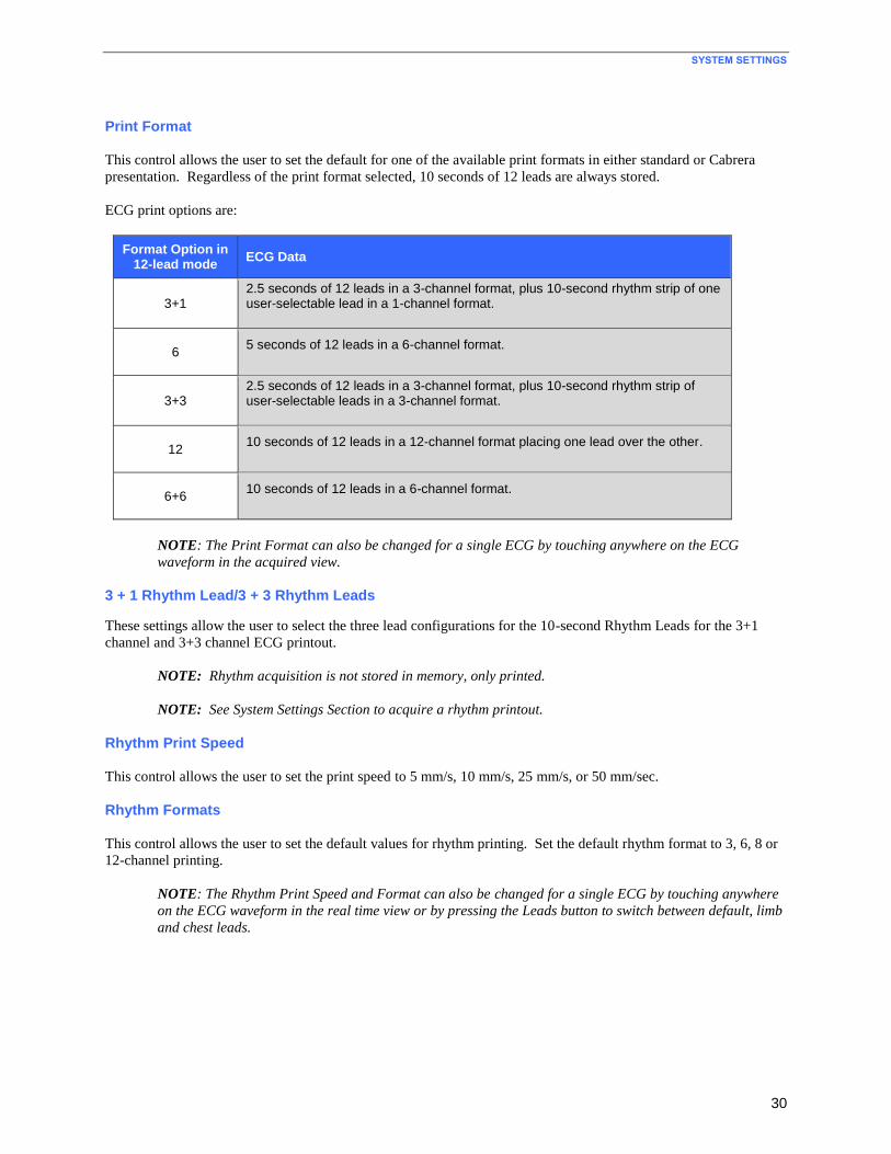
Print Format
This control allows the user to set the default for one of the available print formats in either standard or Cabrera
presentation. Regardless of the print format selected, 10 seconds of 12 leads are always stored.
ECG print options are:
Format Option in 12-lead mode
ECG Data
3+1 2.5 seconds of 12 leads in a 3-channel format, plus 10-second rhythm strip of one user-selectable lead in a 1-channel format.
6 5 seconds of 12 leads in a 6-channel format.
3+3 2.5 seconds of 12 leads in a 3-channel format, plus 10-second rhythm strip of user-selectable leads in a 3-channel format.
12 10 seconds of 12 leads in a 12-channel format placing one lead over the other.
6+6 10 seconds of 12 leads in a 6-channel format.
NOTE: The Print Format can also be changed for a single ECG by touching anywhere on the ECG
waveform in the acquired view.
3 + 1 Rhythm Lead/3 + 3 Rhythm Leads
These settings allow the user to select the three lead configurations for the 10-second Rhythm Leads for the 3+1
channel and 3+3 channel ECG printout.
NOTE: Rhythm acquisition is not stored in memory, only printed.
NOTE: See System Settings Section to acquire a rhythm printout.
Rhythm Print Speed
This control allows the user to set the print speed to 5 mm/s, 10 mm/s, 25 mm/s, or 50 mm/sec.
Rhythm Formats
This control allows the user to set the default values for rhythm printing. Set the default rhythm format to 3, 6, 8 or
12-channel printing.
NOTE: The Rhythm Print Speed and Format can also be changed for a single ECG by touching anywhere
on the ECG waveform in the real time view or by pressing the Leads button to switch between default, limb
and chest leads.
SYSTEM SETTINGS
31
Configuration Settings: LAN
All parameters related to network connection must be entered under the direction of a qualified IT professional of
the facility where the device is installed.
DHCP
This utility allows the IT professional to define whether the Dynamic Host Communication Protocol (DHCP) will be
used to obtain an IP address.
If DHCP is YES, the network will automatically and dynamically assign an IP address.
If DHCP is NO, the IT professional must enter the IP address, def gateway, and subnet mask.
IP Address
This utility allows the IT professional to enter the fixed IP address for network transmission (if DHCP is not
selected).
Def Gateway
This utility allows the IT professional to enter the address of the default gateway (if DHCP is not selected).
Subnet Mask
This utility allows the IT professional to enter the subnet address (if DHCP is not selected).
Sync IP
This utility allows the IT professional to enter the IP address of the host server.
NOTE: Addresses are always entered as 4 sets of 3 digits; therefore, an address of 192.168.0.7 must be
entered as 192.168.000.007.
Port Number
This utility allows the IT professional to enter the port number used by the host server.
SYSTEM SETTINGS
32
Configuration Settings: WLAN
DHCP
This utility allows the IT professional to define whether the Dynamic Host Communication Protocol (DHCP) will be
used to obtain an IP address.
If DHCP is YES, the network will automatically and dynamically assign an IP address.
If DHCP is NO, the IT professional must enter the IP address, def gateway, and subnet mask.
IP Address
This utility allows the IT professional to enter the fixed IP address for network transmission (if DHCP is not
selected).
Def Gateway
This utility allows the IT professional to enter the address of the default gateway (if DHCP is not selected).
Subnet Mask
This utility allows the IT professional to enter the subnet address (if DHCP is not selected).
SSID
Service Set Identifier (SSID) is the name of the wireless network. All ELI 280 electrocardiographs that will transmit
to the same network must have the same SSID name. Touch the field to display the touchscreen keyboard.
PSK Passphrase The passphrase may be from eight to 63 ASCII characters or 64 hexadecimal digits (256 bits). Touch the field to
display the touchscreen keyboard.
Sync IP
This utility allows the IT professional to enter the IP address of the host server.
NOTE: Addresses are always entered as 4 sets of 3 digits; therefore, an address of 192.168.0.7 must be
entered as 192.168.000.007.
Port Number
This utility allows the IT professional to enter the port number used by the host server.
Security (WEP)
Wired Equivalent Privacy (WEP) is an encrypted security protocol (part of the 802.11 standard). Access points can
have multiple WEP keys stored. Each one of them is identified by a number (e.g., 0, 1, 2, 3).
WEP Key
This utility allows the IT professional to enter the WEP key number; valid range is 1-4.
SYSTEM SETTINGS
33
WEP Key ID
This utility allows the IT professional to enter the 128-bit WEP Key ID value (26 digits in 13 sets of two digits).
WPA-PSK
WPA (Wi-Fi Protected Access) PSK (Pre-Shared Key) security allows for implementation of the “personal mode”
of WPA. This mode of encryption employs Temporal Key Integrity Protocol (TKIP) which dynamically changes
keys as the system is used.
WPA-LEAP
Cisco® LEAP (Light Extensible Authorization Protocol) enables use of the device with wireless networks
employing the LEAP encryption protocol.
LEAP User Name
The LEAP user name can be up to 32 characters in length.
LEAP Password The LEAP password can contain up to 32 characters.
EAP-TLS
TLS User Name: The username/EAP identity for the ELI 280. There must be a valid username on the RADIUS
server that matches this name.
TLS Password: The password for the private key file. This is the password used to build the private key file.
Uploading Certificates
The certificate files are uploaded from a USB drive. The files must be in a directory called “Certificates”. The
Certificates directory must be in the root of the USB drive. The CA root certificate file must be named
“ELI280root.cer”. The client certificate file must be named “ELI280client.pem”. The private key file must be named
“ELI280privatekey.pem”. To upload the files, connect the USB drive and click the “Certificates” button at the
bottom of the WLAN configuration screen.
CAUTION. You must enter a User Name and Password before you press Done to save your
settings.
SYSTEM SETTINGS
34
Configuration Settings: Date/Time
Selecting YEAR presents a touch screen keyboard for entry of the correct year in a four character format i.e.: 2012
Selecting MONTH presents a drop down window for entry of the correct month
Selecting DAY presents a drop down window for entry of the correct day. Using the arrows at the bottom of the list
will advance you to the next level of selections.
Selecting HOUR presents a drop down window for entry of the correct hour. Using the arrows at the bottom of the
list will advance you to the next level of selections.
Selecting MINUTE presents a drop down window for entry of the correct minute. Using the arrows at the bottom of
the list will advance you to the next level of selections.
Selecting TIME ZONE presents a drop down window for entry of the correct time zone. Using the arrows at the
bottom of the list will advance you to the next level of selections.
Selecting DAYLIGHT SAVINGS TIME presents a drop down window for entry of a Yes/No selection for
automatic daylight savings time to be communicated from ELI LINK or EScribe.
Configuration Settings: CUSTOM ID
Selecting CUSTOM ID sets communication with ELI Link or EScribe and downloads the custom ID to the ELI 280.
NOTE: Custom ID must be configured in ELI Link or EScribe.
Configuration Settings: NETWORK
Selecting NETWORK establishes communication with the wireless network and displays up to five bars of signal
strength. Presentation of the MAC Address, Firmware module, Radio Firmware, and IP address connected to will
also be presented.
Configuration Settings: WAM
Selecting WAM allows the clinician to switch between WAM or AM12 patient interface cables. For Pairing of the
WAM, please refer to the WAM operator’s manual.
35
PREVENTIVE MAINTENANCE
WARNING
Servicing of this device should only be performed by Welch Allyn authorized service personnel.
Welch Allyn recommends preventive maintenance to be performed on an annual basis.
Caution
Turn off the device before inspecting or cleaning.
Do not immerse the device in water.
Do not use organic solvents, ammonia-based solutions, or abrasive cleaning agents which may damage
equipment surfaces.
Recommended Tools and Supplies
Device Cleaning / Consumables :
Clean lint free cloth
Mild detergent
Isopropyl Alcohol (80-99%)
Cyanoacrylate Adhesive (e.g., Loctite 444 or equivalent product)
Anaerobic Threadlocker (xxx grade)
Smart Thermal Paper
10% Household bleach and water solution (Sodium Hypochlorite solution consisting of a
minimum 1:500 dilution and maximum of 1:10 dilution for disinfecting use only)
Preventive Maintenance / Conformance Testing
Multi-Meter
ECG Simulator (10 Lead)
AM12 Patient Input Module (9293-048-5X)
WAM Patient Input Module (30012-019-5X)
WAM/AM12 Lead Wire Set (9293-046-70)
Patient Cable Snap Adapter Set (9281-002-50)
Phillips #2 Screwdriver
10 Lead Shorting Block (or equivalent)
Lead Test Failure Box (or equivalent)
FAT 32 USB Memory Device
PC with ELI-Link v3.10 or later
USB Cable Type A to B (6400-012)
Phone Cable (6400-004)
PC with ELI-Link or Escribe and Modem (or equivalent)
PC with NIC and ELI-Link v4.5 or later
Wireless Router 802.11 (a, b, g, n)
Electrical Safety Analyzer

PREVENTIVE MAINTENANCE
36
Preventive Maintenance Procedure
Inspection
Print the device configuration (attach to the Preventive Maintenance Report)
Remove the top housing per Unit Disassembly Section of this manual.
Perform a visual inspection of the following items:
Enclosure/Housing – Look for damage or cracks in the external housing or enclosure that could possibly expose the
device to the introduction of foreign objects or fluids. Attention should also be paid to areas that could expose an
operator or patient to internal circuitry of the device.
Contamination – Look for any contamination that may have occurred over time that could not be seen with the
housing in place.
• Fluid damage (perhaps caused during device cleaning)
• Debris on or behind display shield
• Battery leakage
Internal Cabling – Look for cracked, pinched or partially disconnected cable connections.
Fuse Ratings – Verify PCB mounted fuses (F1 and F3) are properly rated at T1A, 250VAC.
Markings and Labeling – Verify all labels and device markings are clearly visible and legible to the device user and
have not been worn off or rendered unreadable through the use of harsh cleaning agents.
Integrity of Mechanical Parts – Verify the following items are properly secured to the device and have not become
loose or damaged through usage over time.
• AC Inlet
• Patient Input Connector
• Communication ports and antenna
• Writer mechanics/latching mechanism
PREVENTIVE MAINTENANCE
37
Device Testing
Power Testing
Ensure battery is fully charged before performing these tests, voltage and current limits are based on a fully
charged battery.
Ensure there is no power connected to the UUT AC inlet.
Turn the unit over and remove the battery plate (see Unit Disassembly section “Battery Removal”). To
gain better access to the terminals, pull the battery out of the compartment. Disconnect the red battery
cable from the red terminal.
NOTE: Based upon customer usage and age of battery, replace as needed.
Note battery age (if possible)
This information can be found on the white “date code” sticker located on the battery (use the
earliest date that is not crossed out). Record date on Preventative Maintenance Report (PMR) .
Battery (open circuit)
Measure battery voltage using a voltage meter; verify the meter reads greater than 12.5vdc.
Record result on PMR.
Battery (load)
Measure the battery voltage using a volt meter and a power resistor load (10ohm, 20watt) in
parallel with the battery. After approximately 5 seconds, verify the meter reads greater than
11.7vdc. Record result on PMR.
Off current
Connect a current meter in line with battery. With the UUT power off, verify the current meter reads less than 250
uA. Record result on PMR.
On current
Turn on the unit (DC) and verify the current meter reads less than 1.1A.
Record result on PMR.
AC charging current
. With the current meter still connected, apply AC power to the unit and verify that the current draw from the battery
reverses polarity and the value starts decreasing as time increases. Record result on PMR.
Battery charger output voltage
Disconnect the current meter and measure the battery charger output voltage between the red
disconnected battery cable and the negative terminal on the battery. It should read between
13.0vdc and 14.7vdc. Record result on PMR.
Reconnect the red battery cable to the red terminal and reinstall the battery and cover plate.
*Note – The touch screen will need to be recalibrated and the date/time will need to be reset every time the battery is
disconnected.
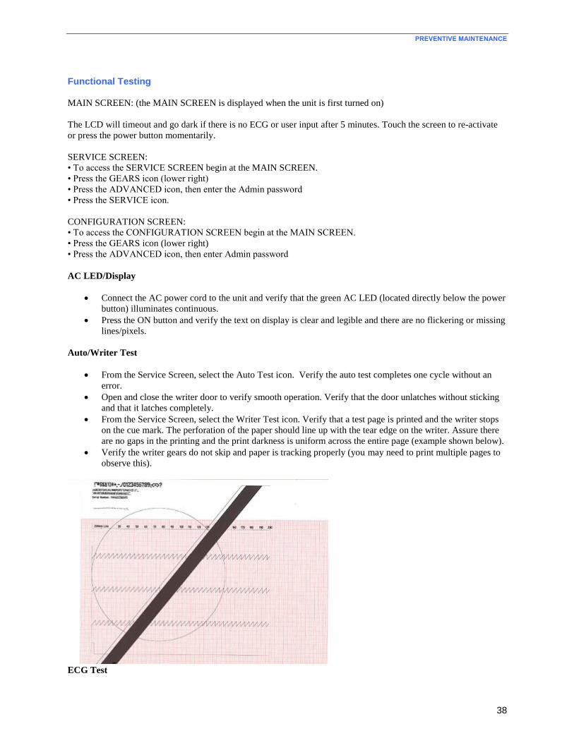
PREVENTIVE MAINTENANCE
38
Functional Testing
MAIN SCREEN: (the MAIN SCREEN is displayed when the unit is first turned on)
The LCD will timeout and go dark if there is no ECG or user input after 5 minutes. Touch the screen to re-activate
or press the power button momentarily.
SERVICE SCREEN:
• To access the SERVICE SCREEN begin at the MAIN SCREEN.
• Press the GEARS icon (lower right)
• Press the ADVANCED icon, then enter the Admin password
• Press the SERVICE icon.
CONFIGURATION SCREEN:
• To access the CONFIGURATION SCREEN begin at the MAIN SCREEN.
• Press the GEARS icon (lower right)
• Press the ADVANCED icon, then enter Admin password
AC LED/Display
Connect the AC power cord to the unit and verify that the green AC LED (located directly below the power
button) illuminates continuous.
Press the ON button and verify the text on display is clear and legible and there are no flickering or missing
lines/pixels.
Auto/Writer Test
From the Service Screen, select the Auto Test icon. Verify the auto test completes one cycle without an
error.
Open and close the writer door to verify smooth operation. Verify that the door unlatches without sticking
and that it latches completely.
From the Service Screen, select the Writer Test icon. Verify that a test page is printed and the writer stops
on the cue mark. The perforation of the paper should line up with the tear edge on the writer. Assure there
are no gaps in the printing and the print darkness is uniform across the entire page (example shown below).
Verify the writer gears do not skip and paper is tracking properly (you may need to print multiple pages to
observe this).
ECG Test

PREVENTIVE MAINTENANCE
39
Connect an ECG simulator to the AM12 or WAM patient interface. Set the simulator to a known heart rate
and amplitude.
From the Main Screen, select the ECG icon to capture an ECG. Enter “TESTECG” in the last name field.
Verify there is an audible beep with each key press.
Verify that 12 ECG traces print correctly and assess the overall printout quality. Ensure uniform darkness
across entire printout.
Communication options
Verify successful transmission of all applicable communication options by transmitting the ECG record stored
earlier to a compatible receiving device.
- USB host (USB memory device needed)
- USBD
- Modem
- LAN
- WLAN
Calibration
Touch Screen Display Calibration
The touch screen display requires calibration upon initial use and at regularly scheduled preventive maintenance
intervals as prescribed in the service manual. To initiate a calibration, press and hold the power button for 20
seconds. Once initiated, the ELI 280 automatically begins the calibration sequence (detailed below). Through on-
screen prompts, the user will touch strategically placed crosshairs to calibrate the display’s touch point accuracy.
1. Initiate the calibration sequence by touching the + symbol in the upper left corner of the display.
2. Touch the + symbol in the upper right corner of the display.
3. Touch the + in the lower right corner of the display.
4. Touch the + in the lower left hand corner of the display.
Cardiograph Calibration
No calibration is needed for the proper operation of the device, other than the item stated above.
PREVENTIVE MAINTENANCE
40
Device Cleaning
Cautions
Improper cleaning products and processes can damage the device, produce brittle lead wires and cables, corrode the
metal, and void the warranty. Use care and proper procedure whenever cleaning or maintaining the device.
Cleaning Exterior Surfaces and Patient Acquisition Device
1. Remove cables and lead wires from device before cleaning.
2. For general cleaning of cables and lead wires, use a soft, lint-free cloth lightly moistened with a mild soap
and water solution. Wipe and air dry.
3. For disinfecting the cables and lead wires, wipe exterior with a soft, lint-free cloth using a solution of
Sodium Hypochlorite (10% household bleach and water solution) minimum 1:500 dilution (minimum 100
ppm free chlorine) and maximum 1:10 dilution as recommended by the APIC Guidelines for Selection and
Use of Disinfectants.
4. Use caution with excess liquid as contact with metal parts may cause corrosion.
5. Do not immerse cable ends or lead wires; immersion can cause metal corrosion.
6. Do not use excessive drying techniques such as forced heat.
WARNING: Prevent liquid from penetrating the device and do not attempt to clean/disinfect the
device or patient cables by submerging into a liquid, autoclaving, or steam cleaning. Never expose cables
to strong ultra-violet radiation. Do not sterilize the device or ECG lead wires with Ethylene
Oxide (EtO) gas.
Cleaning the Device
Disconnect the power source. Clean the exterior surface of the device with a damp, soft, lint-free cloth using a
solution of mild detergent diluted in water. After washing, thoroughly dry off the device with a clean, soft cloth or
paper towel.
Spot Cleaning
The use of Isopropyl Alcohol (80-99%) can be used as a spot cleaner to remove such things as adhesive residue,
marker ink, or stickers that may have been in contact with the device enclosure during use in the field. The alcohol
should be applied by dampening a lint-free cloth or swab applicator to ensure excess fluid spilled into the device.
Once spot cleaning has been completed, the unit should be dried with a dry lint-free cloth.
PREVENTIVE MAINTENANCE
41
Safety Testing
If the cardiograph housing was opened for repair or inspection work, the following safety tests should be performed
in accordance with the IEC 60601-1 or IEC 62353 methods and limits.
The ELI280 is considered a Class 1 Type CF device, intended to only be utilized with the Welch Allyn AM12 or
WAM patient input modules. Defibrillation isolation from the patient is provided by the patient input modules,
which are tested separately as part of the manufacturing process (they are considered non-serviceable devices),
therefore Hi-pot testing is not required for the ELI280 cardiograph.
Earth Leakage
Enclosure Leakage
Non-conductive (fully insulated) chassis testing should be performed utilizing 200 cm2 conductive foil or
equivalent, earth ground on AC input is utilized for functional earth (not safety grounding).
Patient Leakage
Applied part – patient input (utilize Welch Allyn AM12 patient cable)
Patient Auxiliary Current
Applied part – patient input (utilize Welch Allyn AM12 patient cable)
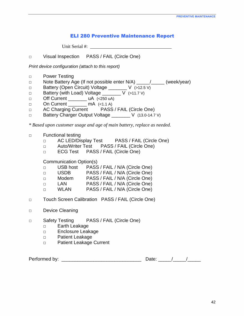
PREVENTIVE MAINTENANCE
42
ELI 280 Preventive Maintenance Report
Unit Serial #: __________________________________
□ Visual Inspection PASS / FAIL (Circle One)
Print device configuration (attach to this report)
□ Power Testing
□ Note Battery Age (If not possible enter N/A) _____/_____ (week/year) □ Battery (Open Circuit) Voltage _______ V (>12.5 V)
□ Battery (with Load) Voltage _______ V (>11.7 V) □ Off Current _______ uA (<250 uA) □ On Current _______ mA (<1.1 A)
□ AC Charging Current PASS / FAIL (Circle One) □ Battery Charger Output Voltage _______ V (13.0-14.7 V)
* Based upon customer usage and age of main battery, replace as needed.
□ Functional testing □ AC LED/Display Test PASS / FAIL (Circle One) □ Auto/Writer Test PASS / FAIL (Circle One) □ ECG Test PASS / FAIL (Circle One)
Communication Option(s) □ USB host PASS / FAIL / N/A (Circle One) □ USDB PASS / FAIL / N/A (Circle One) □ Modem PASS / FAIL / N/A (Circle One) □ LAN PASS / FAIL / N/A (Circle One) □ WLAN PASS / FAIL / N/A (Circle One)
□ Touch Screen Calibration PASS / FAIL (Circle One) □ Device Cleaning
□ Safety Testing PASS / FAIL (Circle One) □ Earth Leakage □ Enclosure Leakage □ Patient Leakage □ Patient Leakage Current Performed by: ______________________________ Date: _____/_____/_____
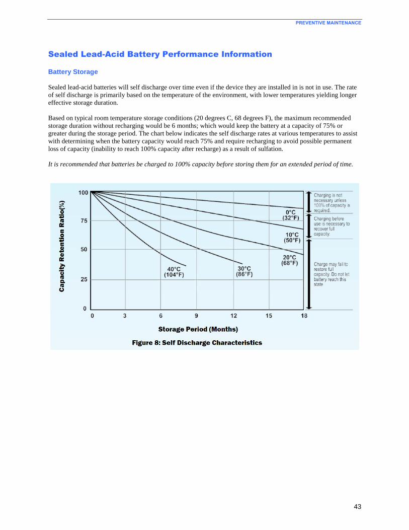
PREVENTIVE MAINTENANCE
43
Sealed Lead-Acid Battery Performance Information
Battery Storage
Sealed lead-acid batteries will self discharge over time even if the device they are installed in is not in use. The rate
of self discharge is primarily based on the temperature of the environment, with lower temperatures yielding longer
effective storage duration.
Based on typical room temperature storage conditions (20 degrees C, 68 degrees F), the maximum recommended
storage duration without recharging would be 6 months; which would keep the battery at a capacity of 75% or
greater during the storage period. The chart below indicates the self discharge rates at various temperatures to assist
with determining when the battery capacity would reach 75% and require recharging to avoid possible permanent
loss of capacity (inability to reach 100% capacity after recharge) as a result of sulfation.
It is recommended that batteries be charged to 100% capacity before storing them for an extended period of time.
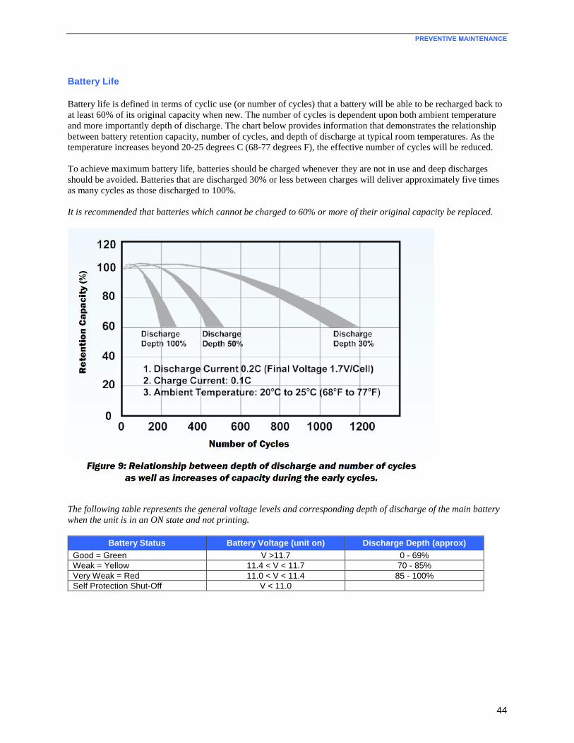
PREVENTIVE MAINTENANCE
44
Battery Life
Battery life is defined in terms of cyclic use (or number of cycles) that a battery will be able to be recharged back to
at least 60% of its original capacity when new. The number of cycles is dependent upon both ambient temperature
and more importantly depth of discharge. The chart below provides information that demonstrates the relationship
between battery retention capacity, number of cycles, and depth of discharge at typical room temperatures. As the
temperature increases beyond 20-25 degrees C (68-77 degrees F), the effective number of cycles will be reduced.
To achieve maximum battery life, batteries should be charged whenever they are not in use and deep discharges
should be avoided. Batteries that are discharged 30% or less between charges will deliver approximately five times
as many cycles as those discharged to 100%.
It is recommended that batteries which cannot be charged to 60% or more of their original capacity be replaced.
The following table represents the general voltage levels and corresponding depth of discharge of the main battery
when the unit is in an ON state and not printing.
Battery Status Battery Voltage (unit on) Discharge Depth (approx)
Good = Green V >11.7 0 - 69%
Weak = Yellow 11.4 < V < 11.7 70 - 85%
Very Weak = Red 11.0 < V < 11.4 85 - 100%
Self Protection Shut-Off V < 11.0
45
UNIT DISASSEMBLY
This section describes the methods used to disassemble and repair the ELI280 and the tools required to perform the
defined steps.
Cautions and Special Instructions
CAUTION: Risk of Explosion - DO NOT SHORT battery terminals. Leave the protective covers on the
battery terminals until assembly into the base unit.
CAUTION: Risk of Shock – Line voltage may be present on the power supply of the device. Use caution
when the device housing is removed and AC power is applied.
ATTENTION: PCB assembly contains ESD sensitive devices. Use appropriate precaution when handling
electronic assemblies.
ATTENTION: PCB assembly contains mechanically sensitive electrical devices. Handle with extreme
care to reduce the stress on solder connections.
ATTENTION: Before applying all adhesive backed materials, clean surface with alcohol to make sure it
is clean and oil free.
Tools Required
T10 Torx Driver Bit
Phillips #2 Driver Bit
Torque Driver (2 in/lbs)
Torque Driver (3.5 in/lbs)
Torque Driver (5 in/lbs)
Needle Nose Pliers
Phillips #2 Screwdriver
Torque Wrench 8mm- 9.0 inch-pound hand wrench
Side Cutters
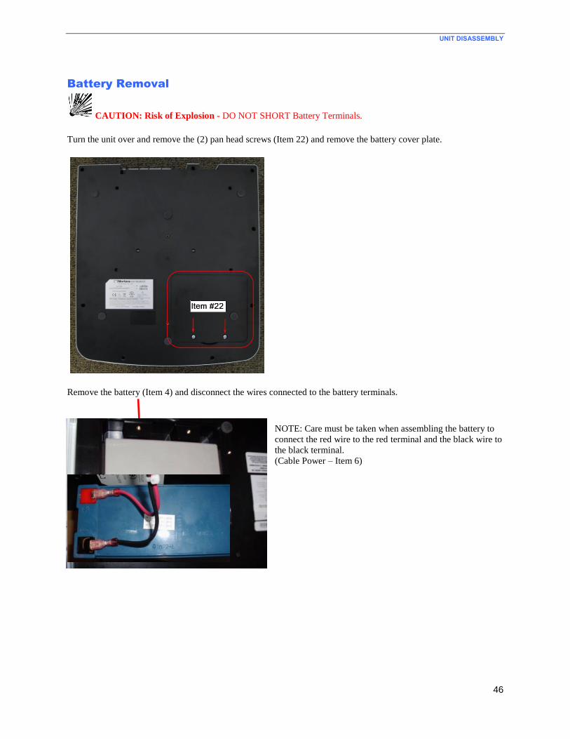
UNIT DISASSEMBLY
46
Battery Removal
CAUTION: Risk of Explosion - DO NOT SHORT Battery Terminals.
Turn the unit over and remove the (2) pan head screws (Item 22) and remove the battery cover plate.
Remove the battery (Item 4) and disconnect the wires connected to the battery terminals.
NOTE: Care must be taken when assembling the battery to
connect the red wire to the red terminal and the black wire to
the black terminal.
(Cable Power – Item 6)
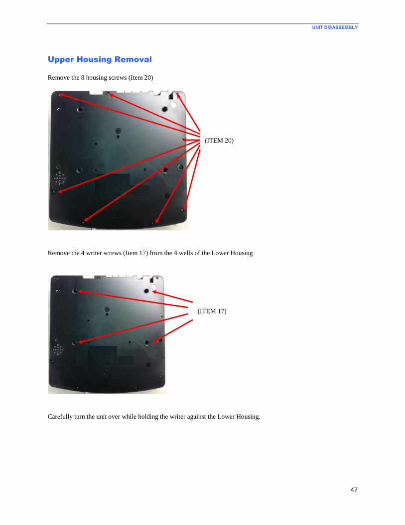
UNIT DISASSEMBLY
47
Upper Housing Removal
Remove the 8 housing screws (Item 20)
Remove the 4 writer screws (Item 17) from the 4 wells of the Lower Housing
Carefully turn the unit over while holding the writer against the Lower Housing.
(ITEM 20)
(ITEM 17)
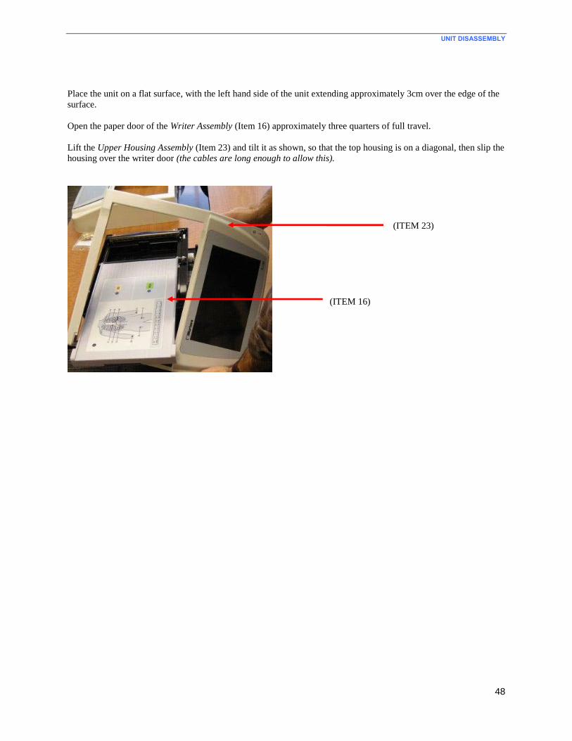
UNIT DISASSEMBLY
48
Place the unit on a flat surface, with the left hand side of the unit extending approximately 3cm over the edge of the
surface.
Open the paper door of the Writer Assembly (Item 16) approximately three quarters of full travel.
Lift the Upper Housing Assembly (Item 23) and tilt it as shown, so that the top housing is on a diagonal, then slip the
housing over the writer door (the cables are long enough to allow this).
(ITEM 23)
(ITEM 16)
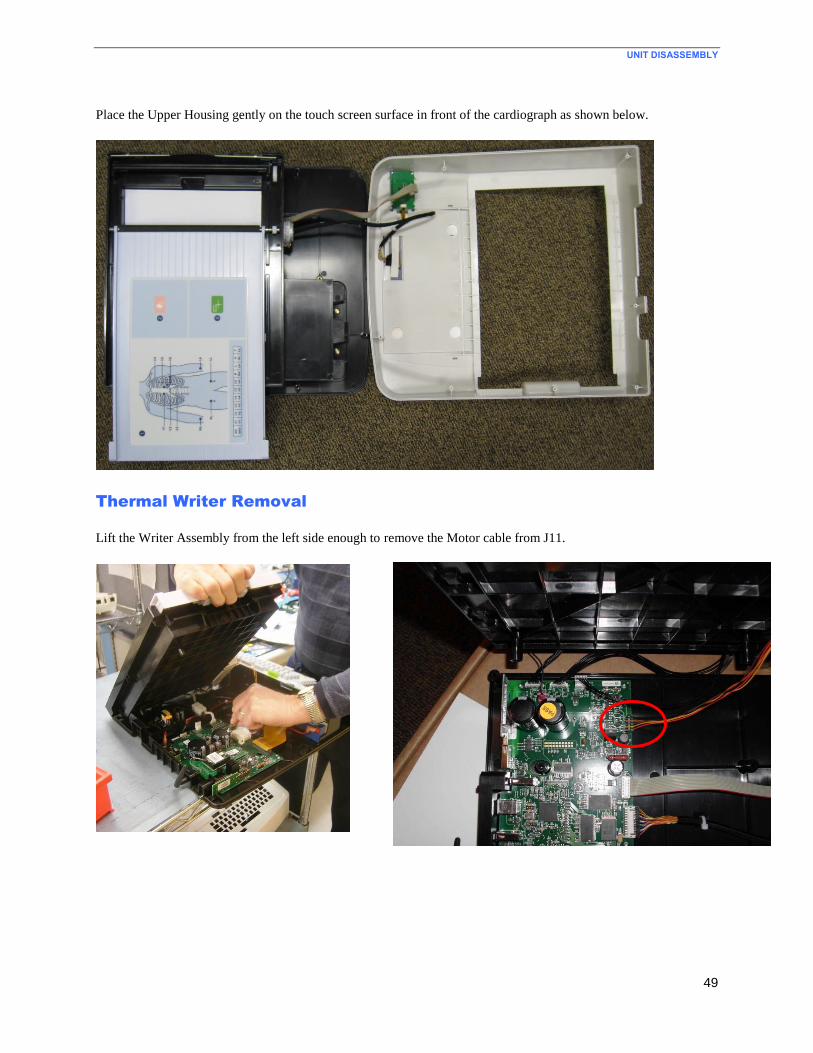
UNIT DISASSEMBLY
49
Place the Upper Housing gently on the touch screen surface in front of the cardiograph as shown below.
Thermal Writer Removal
Lift the Writer Assembly from the left side enough to remove the Motor cable from J11.
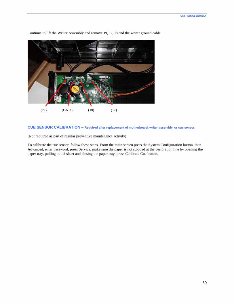
UNIT DISASSEMBLY
50
Continue to lift the Writer Assembly and remove J9, J7, J8 and the writer ground cable.
CUE SENSOR CALIBRATION – Required after replacement of motherboard, writer assembly, or cue sensor.
(Not required as part of regular preventive maintenance activity)
To calibrate the cue sensor, follow these steps. From the main screen press the System Configuration button, then
Advanced, enter password, press Service, make sure the paper is not stopped at the perforation line by opening the
paper tray, pulling out ½ sheet and closing the paper tray, press Calibrate Cue button.
(J8) (J7) (J9) (GND)
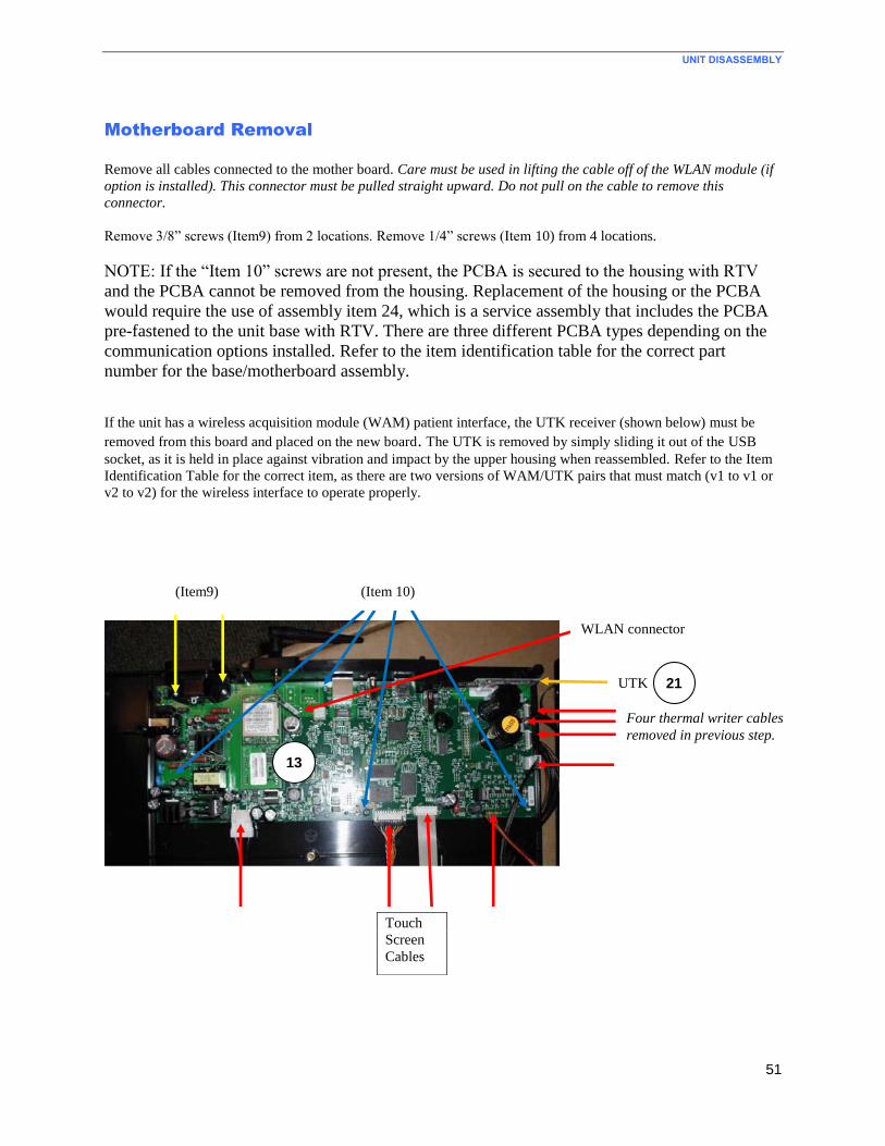
UNIT DISASSEMBLY
51
Motherboard Removal
Remove all cables connected to the mother board. Care must be used in lifting the cable off of the WLAN module (if
option is installed). This connector must be pulled straight upward. Do not pull on the cable to remove this
connector.
Remove 3/8” screws (Item9) from 2 locations. Remove 1/4” screws (Item 10) from 4 locations.
NOTE: If the “Item 10” screws are not present, the PCBA is secured to the housing with RTV
and the PCBA cannot be removed from the housing. Replacement of the housing or the PCBA
would require the use of assembly item 24, which is a service assembly that includes the PCBA
pre-fastened to the unit base with RTV. There are three different PCBA types depending on the
communication options installed. Refer to the item identification table for the correct part
number for the base/motherboard assembly.
If the unit has a wireless acquisition module (WAM) patient interface, the UTK receiver (shown below) must be
removed from this board and placed on the new board. The UTK is removed by simply sliding it out of the USB
socket, as it is held in place against vibration and impact by the upper housing when reassembled. Refer to the Item
Identification Table for the correct item, as there are two versions of WAM/UTK pairs that must match (v1 to v1 or
v2 to v2) for the wireless interface to operate properly.
WLAN connector
Four thermal writer cables
removed in previous step.
(Item9) (Item 10)
13
Touch
Screen
Cables
UTK 21
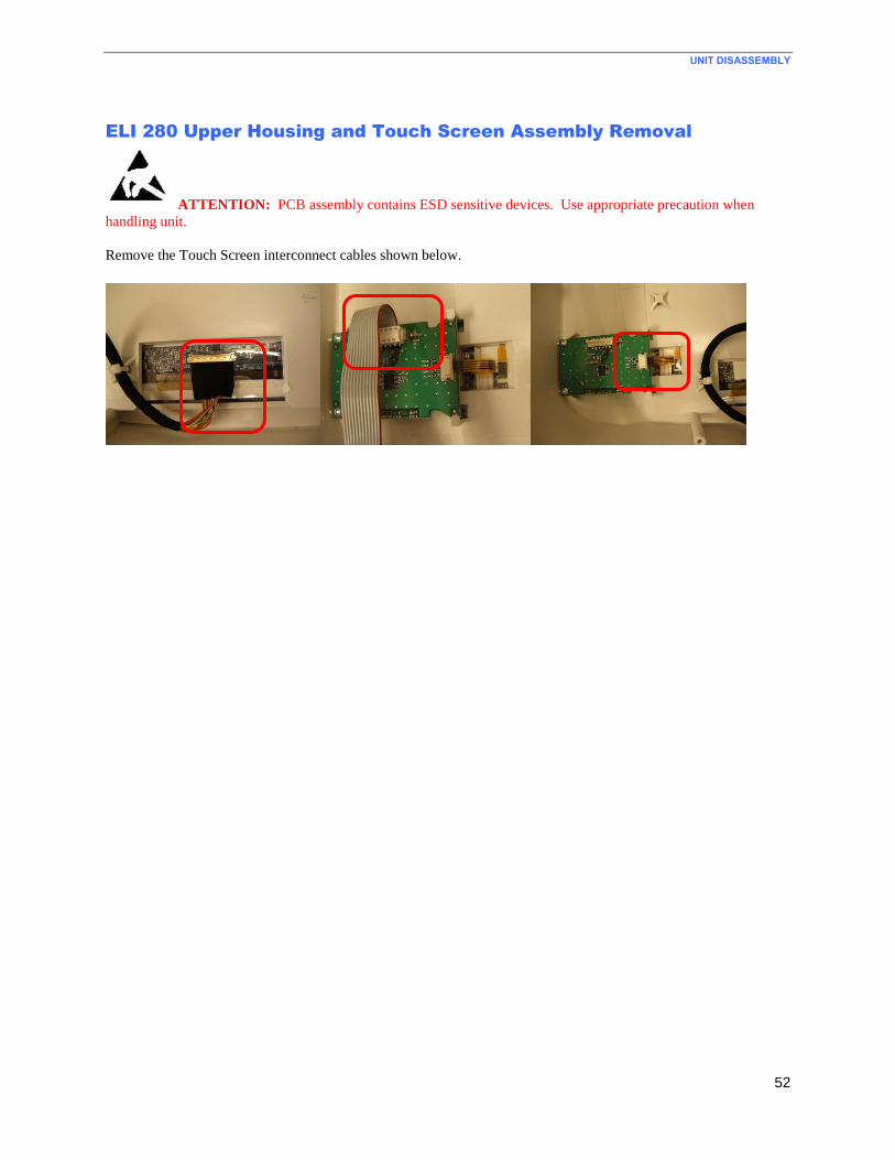
UNIT DISASSEMBLY
52
ELI 280 Upper Housing and Touch Screen Assembly Removal
ATTENTION: PCB assembly contains ESD sensitive devices. Use appropriate precaution when
handling unit.
Remove the Touch Screen interconnect cables shown below.
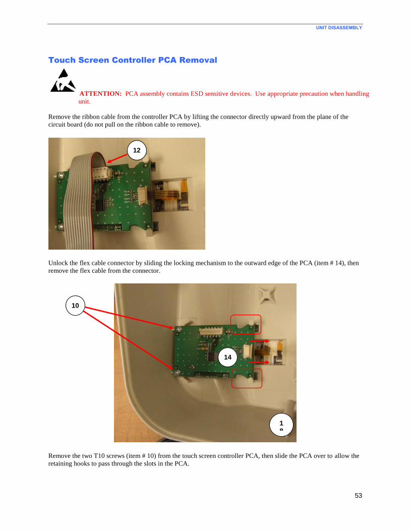
UNIT DISASSEMBLY
53
Touch Screen Controller PCA Removal
ATTENTION: PCA assembly contains ESD sensitive devices. Use appropriate precaution when handling
unit.
Remove the ribbon cable from the controller PCA by lifting the connector directly upward from the plane of the
circuit board (do not pull on the ribbon cable to remove).
Unlock the flex cable connector by sliding the locking mechanism to the outward edge of the PCA (item # 14), then
remove the flex cable from the connector.
Remove the two T10 screws (item # 10) from the touch screen controller PCA, then slide the PCA over to allow the
retaining hooks to pass through the slots in the PCA.
18
10
14
12
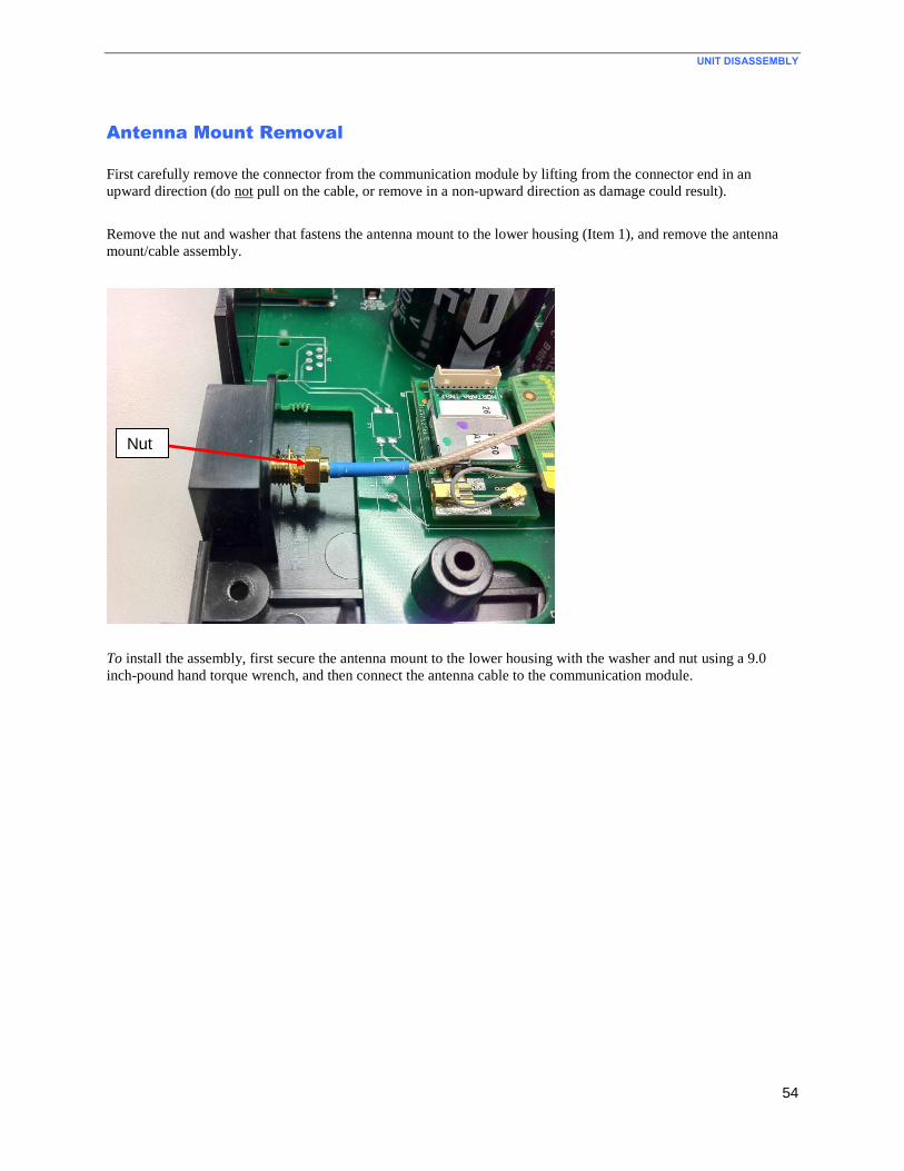
UNIT DISASSEMBLY
54
Antenna Mount Removal
First carefully remove the connector from the communication module by lifting from the connector end in an
upward direction (do not pull on the cable, or remove in a non-upward direction as damage could result).
Remove the nut and washer that fastens the antenna mount to the lower housing (Item 1), and remove the antenna
mount/cable assembly.
To install the assembly, first secure the antenna mount to the lower housing with the washer and nut using a 9.0
inch-pound hand torque wrench, and then connect the antenna cable to the communication module.
Nut
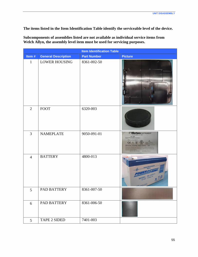
UNIT DISASSEMBLY
55
The items listed in the Item Identification Table identify the serviceable level of the device.
Subcomponents of assemblies listed are not available as individual service items from
Welch Allyn, the assembly level item must be used for servicing purposes.
Item Identification Table
Item # General Description Part Number Picture
1 LOWER HOUSING 8361-002-50
2 FOOT 6320-003
3 NAMEPLATE 9050-091-01
4 BATTERY 4800-013
5 PAD BATTERY 8361-007-50
6 PAD BATTERY 8361-006-50
5 TAPE 2 SIDED 7401-003
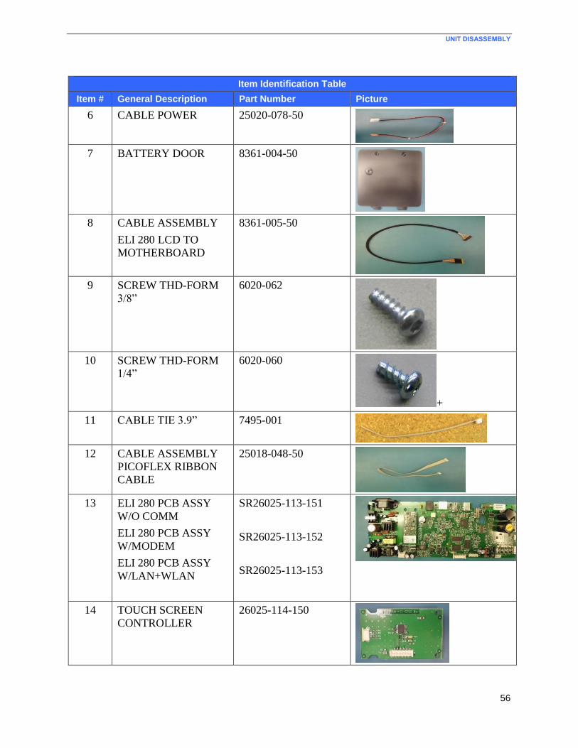
UNIT DISASSEMBLY
56
Item Identification Table
Item # General Description Part Number Picture
6 CABLE POWER 25020-078-50
7 BATTERY DOOR 8361-004-50
8 CABLE ASSEMBLY
ELI 280 LCD TO
MOTHERBOARD
8361-005-50
9 SCREW THD-FORM
3/8”
6020-062
10 SCREW THD-FORM
1/4”
6020-060
+
11 CABLE TIE 3.9” 7495-001
12 CABLE ASSEMBLY
PICOFLEX RIBBON
CABLE
25018-048-50
13 ELI 280 PCB ASSY
W/O COMM
ELI 280 PCB ASSY
W/MODEM
ELI 280 PCB ASSY
W/LAN+WLAN
SR26025-113-151
SR26025-113-152
SR26025-113-153
14 TOUCH SCREEN
CONTROLLER
26025-114-150
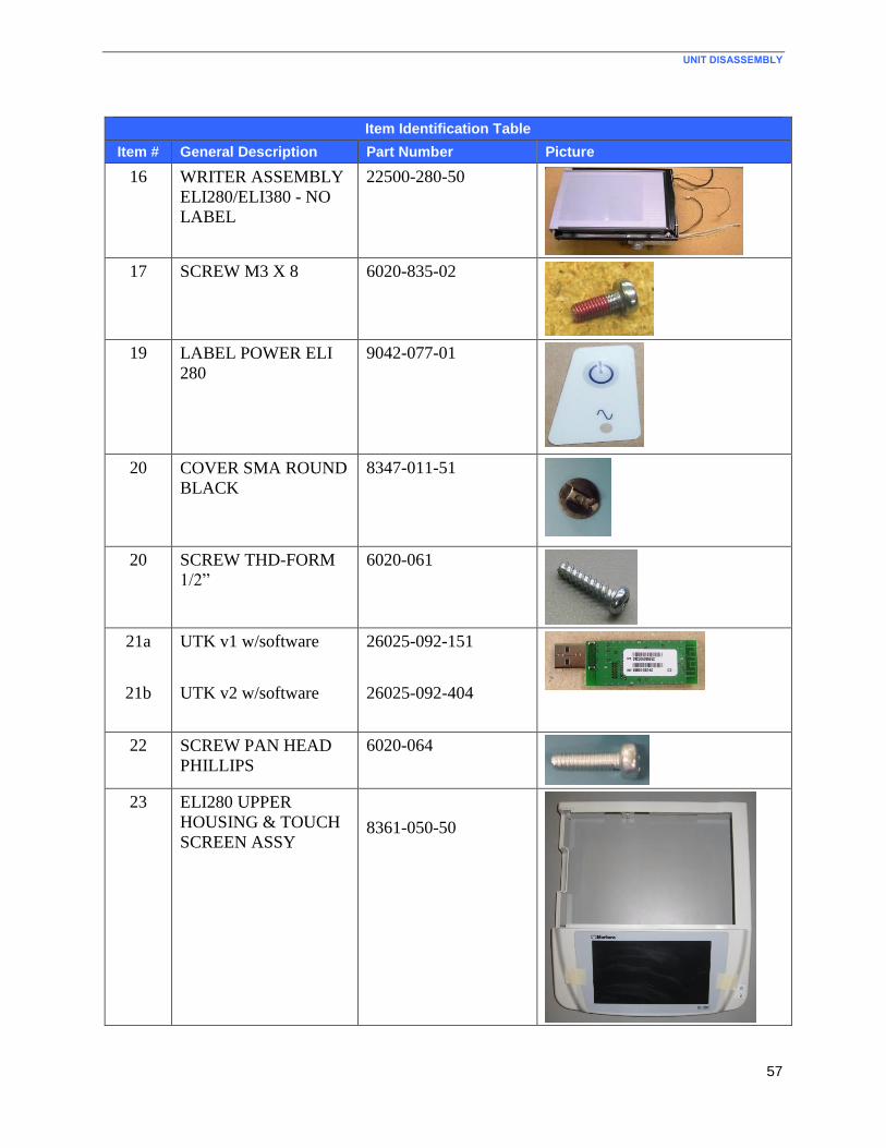
UNIT DISASSEMBLY
57
Item Identification Table
Item # General Description Part Number Picture
16 WRITER ASSEMBLY
ELI280/ELI380 - NO
LABEL
22500-280-50
17 SCREW M3 X 8 6020-835-02
19 LABEL POWER ELI
280
9042-077-01
20 COVER SMA ROUND
BLACK
8347-011-51
20 SCREW THD-FORM
1/2”
6020-061
21a
21b
UTK v1 w/software
UTK v2 w/software
26025-092-151
26025-092-404
22 SCREW PAN HEAD
PHILLIPS
6020-064
23 ELI280 UPPER
HOUSING & TOUCH
SCREEN ASSY
8361-050-50
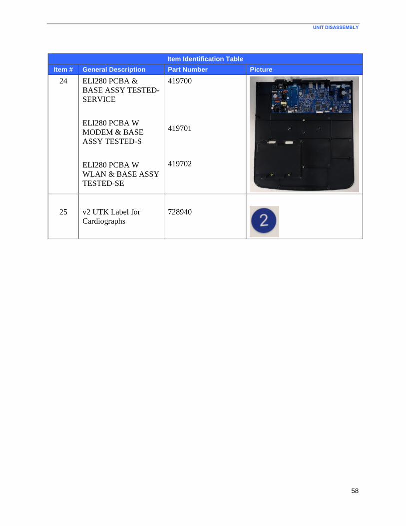
UNIT DISASSEMBLY
58
Item Identification Table
Item # General Description Part Number Picture
24 ELI280 PCBA &
BASE ASSY TESTED-
SERVICE
ELI280 PCBA W
MODEM & BASE
ASSY TESTED-S
ELI280 PCBA W
WLAN & BASE ASSY
TESTED-SE
419700
419701
419702
25
v2 UTK Label for
Cardiographs
728940
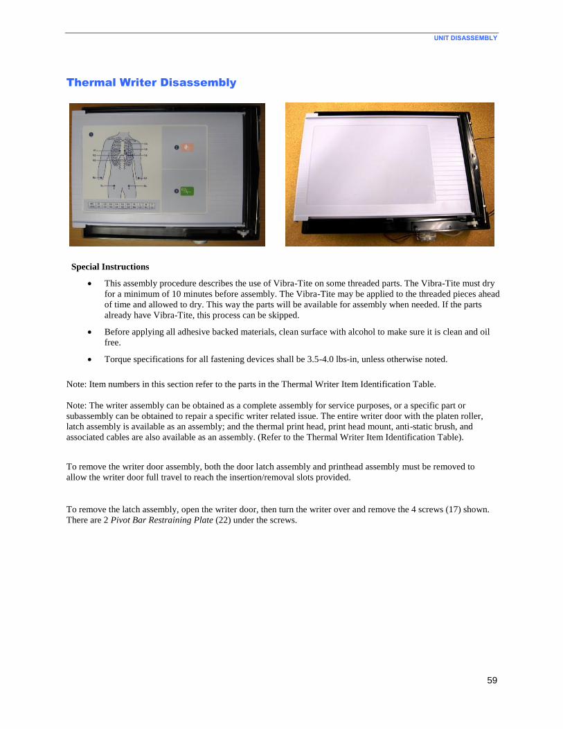
UNIT DISASSEMBLY
59
Thermal Writer Disassembly
Special Instructions
This assembly procedure describes the use of Vibra-Tite on some threaded parts. The Vibra-Tite must dry
for a minimum of 10 minutes before assembly. The Vibra-Tite may be applied to the threaded pieces ahead
of time and allowed to dry. This way the parts will be available for assembly when needed. If the parts
already have Vibra-Tite, this process can be skipped.
Before applying all adhesive backed materials, clean surface with alcohol to make sure it is clean and oil
free.
Torque specifications for all fastening devices shall be 3.5-4.0 lbs-in, unless otherwise noted.
Note: Item numbers in this section refer to the parts in the Thermal Writer Item Identification Table.
Note: The writer assembly can be obtained as a complete assembly for service purposes, or a specific part or
subassembly can be obtained to repair a specific writer related issue. The entire writer door with the platen roller,
latch assembly is available as an assembly; and the thermal print head, print head mount, anti-static brush, and
associated cables are also available as an assembly. (Refer to the Thermal Writer Item Identification Table).
To remove the writer door assembly, both the door latch assembly and printhead assembly must be removed to
allow the writer door full travel to reach the insertion/removal slots provided.
To remove the latch assembly, open the writer door, then turn the writer over and remove the 4 screws (17) shown.
There are 2 Pivot Bar Restraining Plate (22) under the screws.
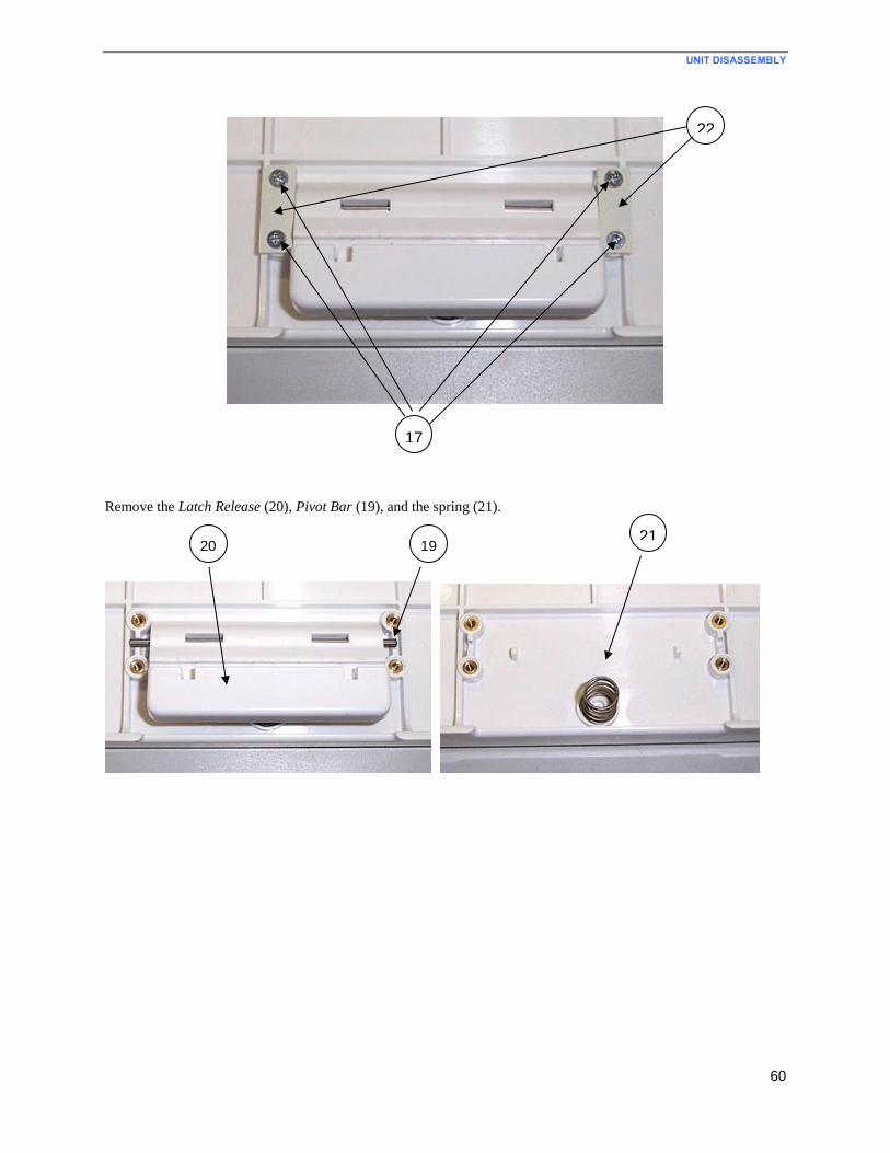
UNIT DISASSEMBLY
60
Remove the Latch Release (20), Pivot Bar (19), and the spring (21).
17
22
20 19 21
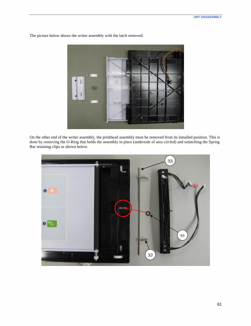
UNIT DISASSEMBLY
61
The picture below shows the writer assembly with the latch removed.
On the other end of the writer assembly, the printhead assembly must be removed from its installed position. This is
done by removing the O-Ring that holds the assembly in place (underside of area circled) and unlatching the Spring
Bar retaining clips as shown below.
33
31
32
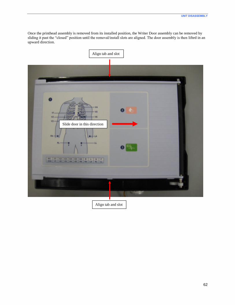
UNIT DISASSEMBLY
62
Once the printhead assembly is removed from its installed position, the Writer Door assembly can be removed by
sliding it past the “closed” position until the removal/install slots are aligned. The door assembly is then lifted in an
upward direction.
Slide door in this direction
Align tab and slot
Align tab and slot
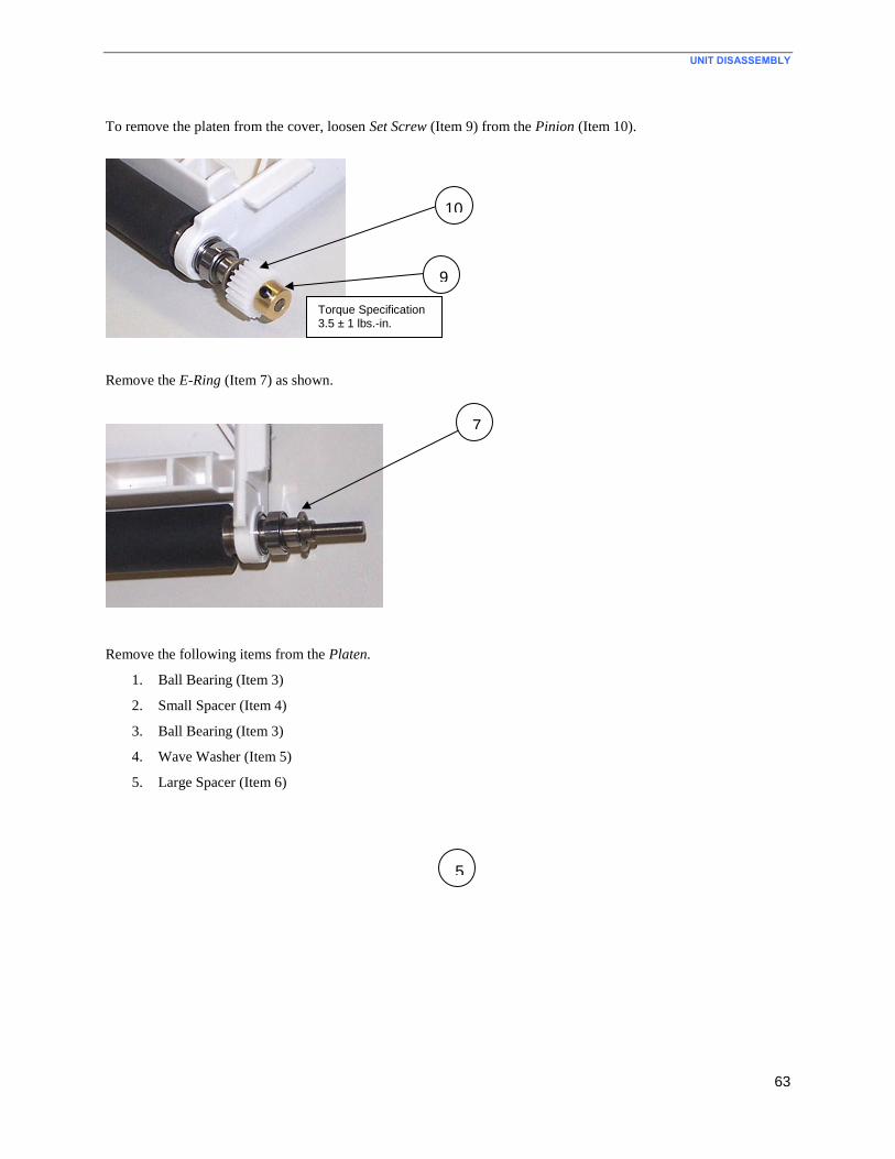
UNIT DISASSEMBLY
63
To remove the platen from the cover, loosen Set Screw (Item 9) from the Pinion (Item 10).
Remove the E-Ring (Item 7) as shown.
Remove the following items from the Platen.
1. Ball Bearing (Item 3)
2. Small Spacer (Item 4)
3. Ball Bearing (Item 3)
4. Wave Washer (Item 5)
5. Large Spacer (Item 6)
9
100
Torque Specification 3.5 ± 1 lbs.-in.
7
555
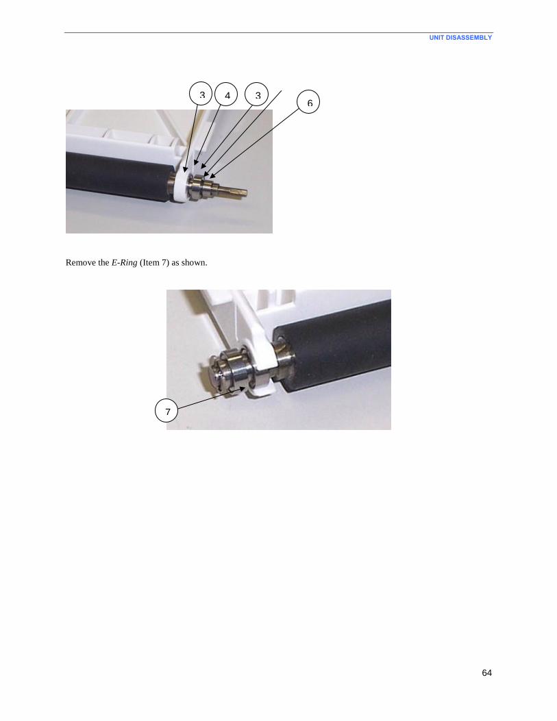
UNIT DISASSEMBLY
64
Remove the E-Ring (Item 7) as shown.
3 44
3 6
7
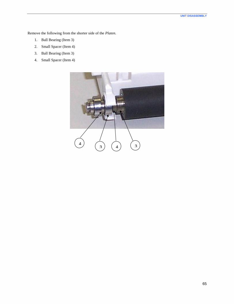
UNIT DISASSEMBLY
65
Remove the following from the shorter side of the Platen.
1. Ball Bearing (Item 3)
2. Small Spacer (Item 4)
3. Ball Bearing (Item 3)
4. Small Spacer (Item 4)
4 3 3 4444

UNIT DISASSEMBLY
66
Gearbox and Motor
Turn the paper tray over and remove the 3 screws (18) to release the gearbox assembly.
Remove the stepper motor from the Gear Box (Item 16) by removing 2 screws (17).
Remove the set screw (9), to remove the Stepper Motor (15).
18
9
15
17
16
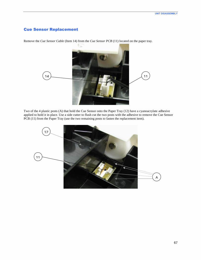
UNIT DISASSEMBLY
67
Cue Sensor Replacement
Remove the Cue Sensor Cable (Item 14) from the Cue Sensor PCB (11) located on the paper tray.
Two of the 4 plastic posts (A) that hold the Cue Sensor onto the Paper Tray (12) have a cyanoacrylate adhesive
applied to hold it in place. Use a side cutter to flush cut the two posts with the adhesive to remove the Cue Sensor
PCB (11) from the Paper Tray (use the two remaining posts to fasten the replacement item).
14
12
A
11
11
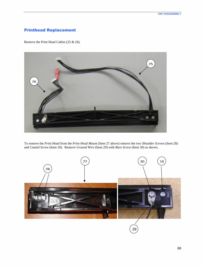
UNIT DISASSEMBLY
68
Printhead Replacement
Remove the Print Head Cables (25 & 26).
To remove the Print Head from the Print Head Mount (Item 27 above) remove the two Shoulder Screws (Item 28)
and Coated Screw (Item 18). Remove Ground Wire (Item 29) with Bare Screw (Item 30) as shown.
26
29
18 30
28
25
27

UNIT DISASSEMBLY
69
When reinstalling the printhead assembly, create a loop with the ground wire to allow it to move freely within the
provided slot.
ELI 280 Writer A4/Smart paper Spacer
If A4/Smart paper Spacer is part of configuration, install A4/Smart paper Spacer into Paper Tray as shown. Snap
into place.
A4/Smart paper Spacer
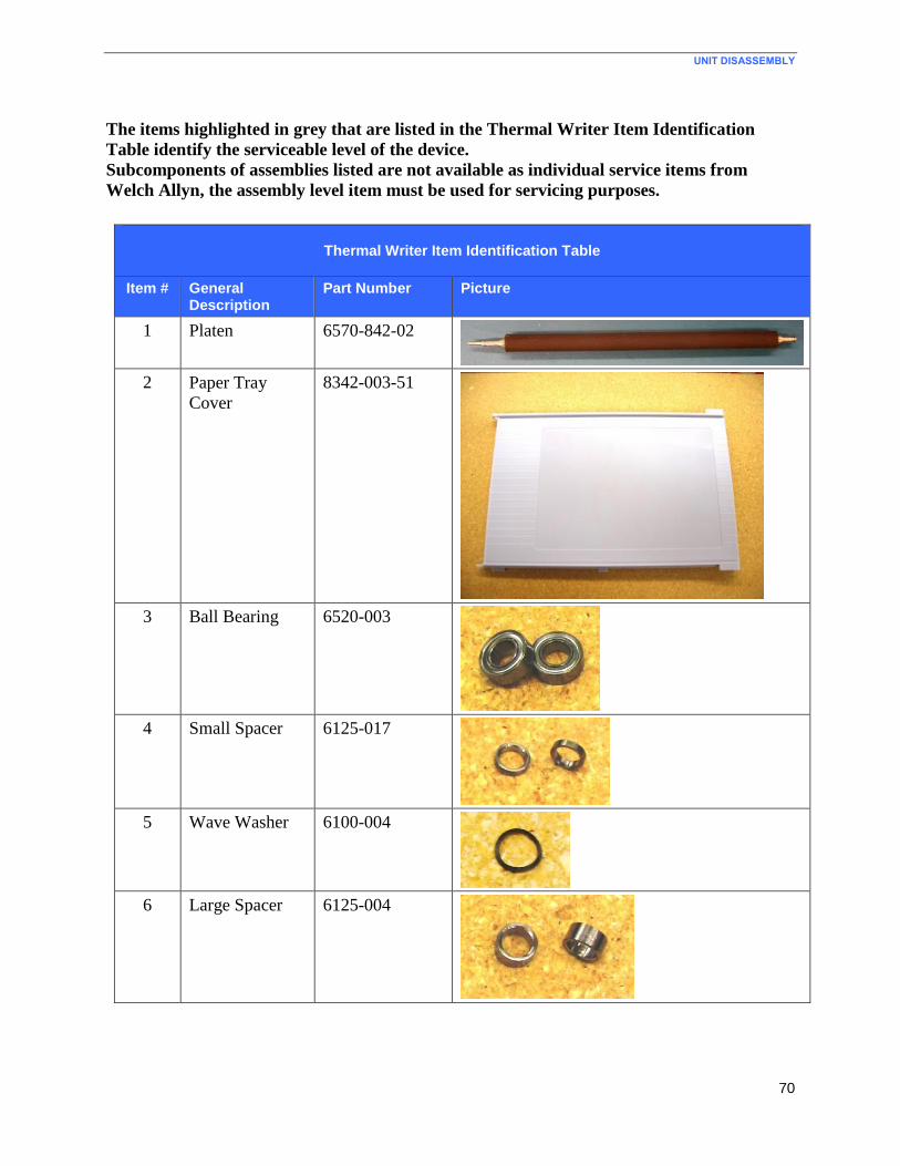
UNIT DISASSEMBLY
70
The items highlighted in grey that are listed in the Thermal Writer Item Identification
Table identify the serviceable level of the device.
Subcomponents of assemblies listed are not available as individual service items from
Welch Allyn, the assembly level item must be used for servicing purposes.
Thermal Writer Item Identification Table
Item # General Description
Part Number Picture
1 Platen 6570-842-02
2 Paper Tray
Cover
8342-003-51
3 Ball Bearing 6520-003
4 Small Spacer 6125-017
5 Wave Washer 6100-004
6 Large Spacer 6125-004
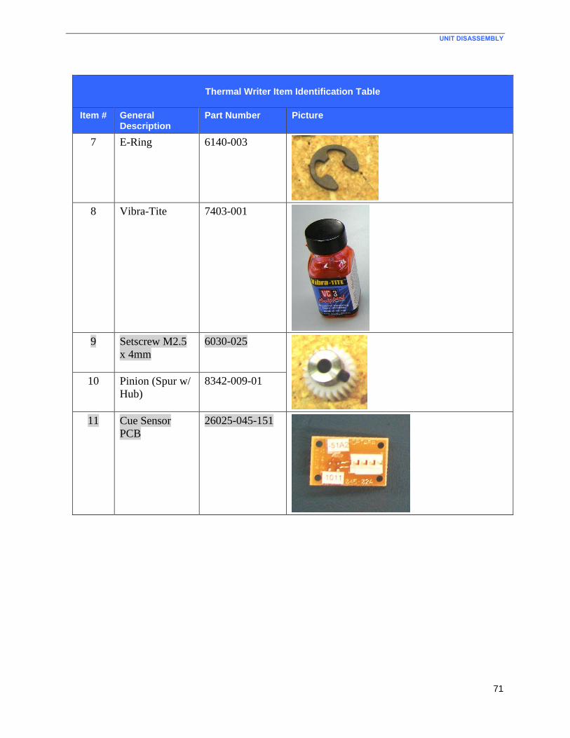
UNIT DISASSEMBLY
71
Thermal Writer Item Identification Table
Item # General Description
Part Number Picture
7 E-Ring 6140-003
8 Vibra-Tite 7403-001
9 Setscrew M2.5
x 4mm
6030-025
10 Pinion (Spur w/
Hub)
8342-009-01
11 Cue Sensor
PCB
26025-045-151
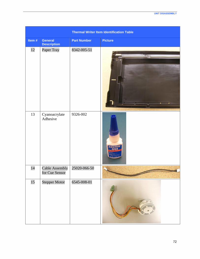
UNIT DISASSEMBLY
72
Thermal Writer Item Identification Table
Item # General Description
Part Number Picture
12 Paper Tray 8342-005-51
13 Cyanoacrylate
Adhesive
9326-002
14 Cable Assembly
for Cue Sensor
25020-066-50
15 Stepper Motor 6545-008-01
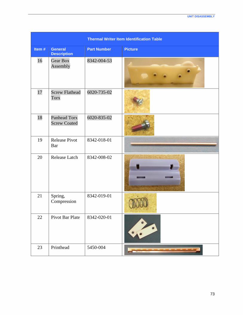
UNIT DISASSEMBLY
73
Thermal Writer Item Identification Table
Item # General Description
Part Number Picture
16 Gear Box
Assembly
8342-004-53
17 Screw Flathead
Torx
6020-735-02
18 Panhead Torx
Screw Coated
6020-835-02
19 Release Pivot
Bar
8342-018-01
20 Release Latch 8342-008-02
21 Spring,
Compression
8342-019-01
22 Pivot Bar Plate 8342-020-01
23 Printhead 5450-004
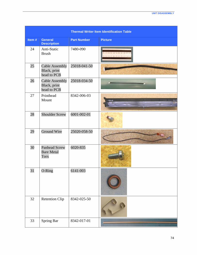
UNIT DISASSEMBLY
74
Thermal Writer Item Identification Table
Item # General Description
Part Number Picture
24 Anti-Static
Brush
7480-090
25 Cable Assembly
Black, print
head to PCB
25018-041-50
26 Cable Assembly
Black, print
head to PCB
25018-034-50
27 Printhead
Mount
8342-006-03
28 Shoulder Screw 6001-002-01
29 Ground Wire 25020-058-50
30 Panhead Screw
Bare Metal
Torx
6020-835
31 O-Ring 6141-003
32 Retention Clip 8342-025-50
33 Spring Bar 8342-017-01
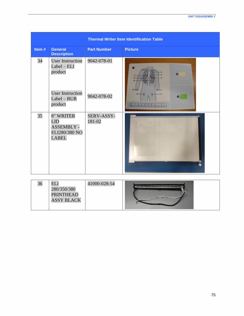
UNIT DISASSEMBLY
75
Thermal Writer Item Identification Table
Item # General Description
Part Number Picture
34 User Instruction
Label – ELI
product
User Instruction
Label – BUR
product
9042-078-01
9042-078-02
35 8" WRITER
LID
ASSEMBLY -
ELI280/380 NO
LABEL
SERV-ASSY-
181-02
36 ELI
280/350/380
PRINTHEAD
ASSY BLACK
41000-028-54
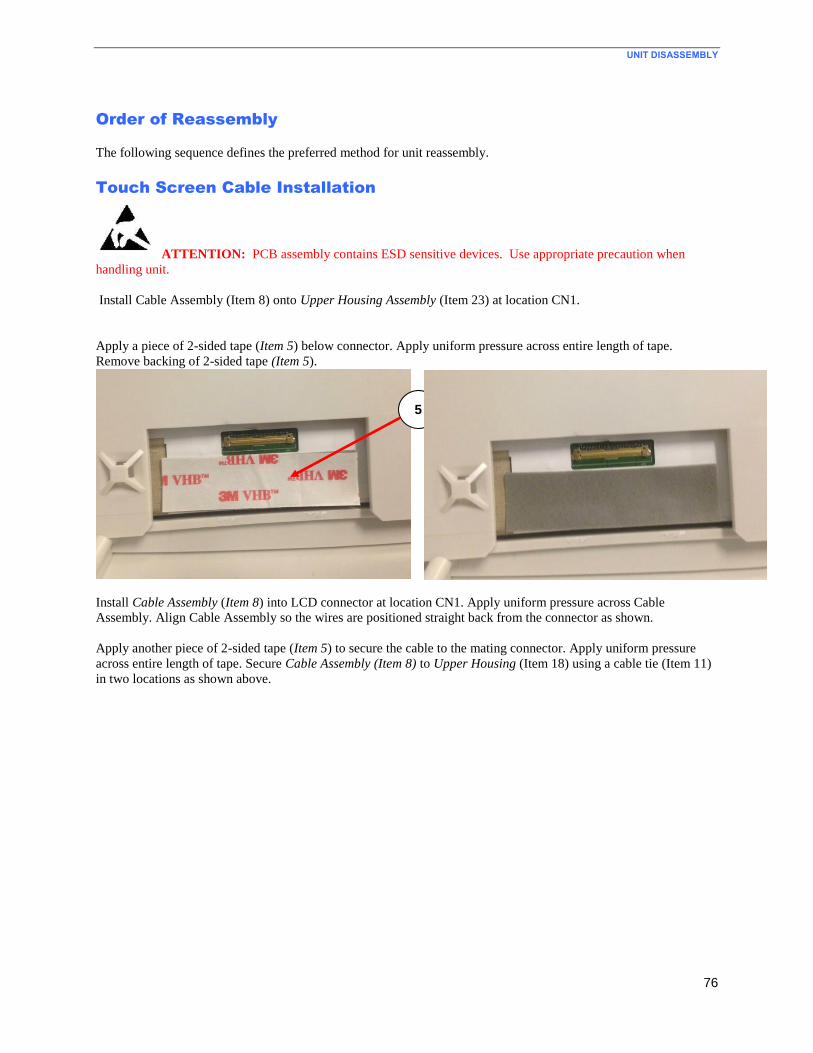
UNIT DISASSEMBLY
76
Order of Reassembly
The following sequence defines the preferred method for unit reassembly.
Touch Screen Cable Installation
ATTENTION: PCB assembly contains ESD sensitive devices. Use appropriate precaution when
handling unit.
Install Cable Assembly (Item 8) onto Upper Housing Assembly (Item 23) at location CN1.
Apply a piece of 2-sided tape (Item 5) below connector. Apply uniform pressure across entire length of tape.
Remove backing of 2-sided tape (Item 5).
Install Cable Assembly (Item 8) into LCD connector at location CN1. Apply uniform pressure across Cable
Assembly. Align Cable Assembly so the wires are positioned straight back from the connector as shown.
Apply another piece of 2-sided tape (Item 5) to secure the cable to the mating connector. Apply uniform pressure
across entire length of tape. Secure Cable Assembly (Item 8) to Upper Housing (Item 18) using a cable tie (Item 11)
in two locations as shown above.
5
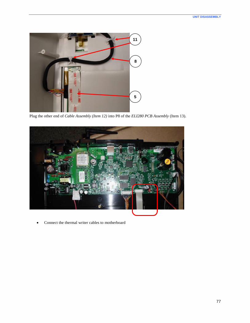
UNIT DISASSEMBLY
77
Plug the other end of Cable Assembly (Item 12) into P8 of the ELI280 PCB Assembly (Item 13).
Connect the thermal writer cables to motherboard
8
5
11
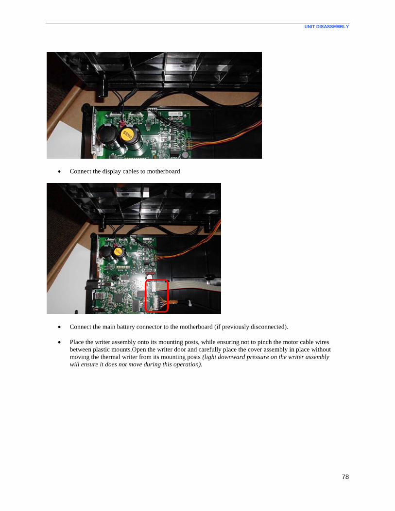
UNIT DISASSEMBLY
78
Connect the display cables to motherboard
Connect the main battery connector to the motherboard (if previously disconnected).
Place the writer assembly onto its mounting posts, while ensuring not to pinch the motor cable wires
between plastic mounts.Open the writer door and carefully place the cover assembly in place without
moving the thermal writer from its mounting posts (light downward pressure on the writer assembly
will ensure it does not move during this operation).
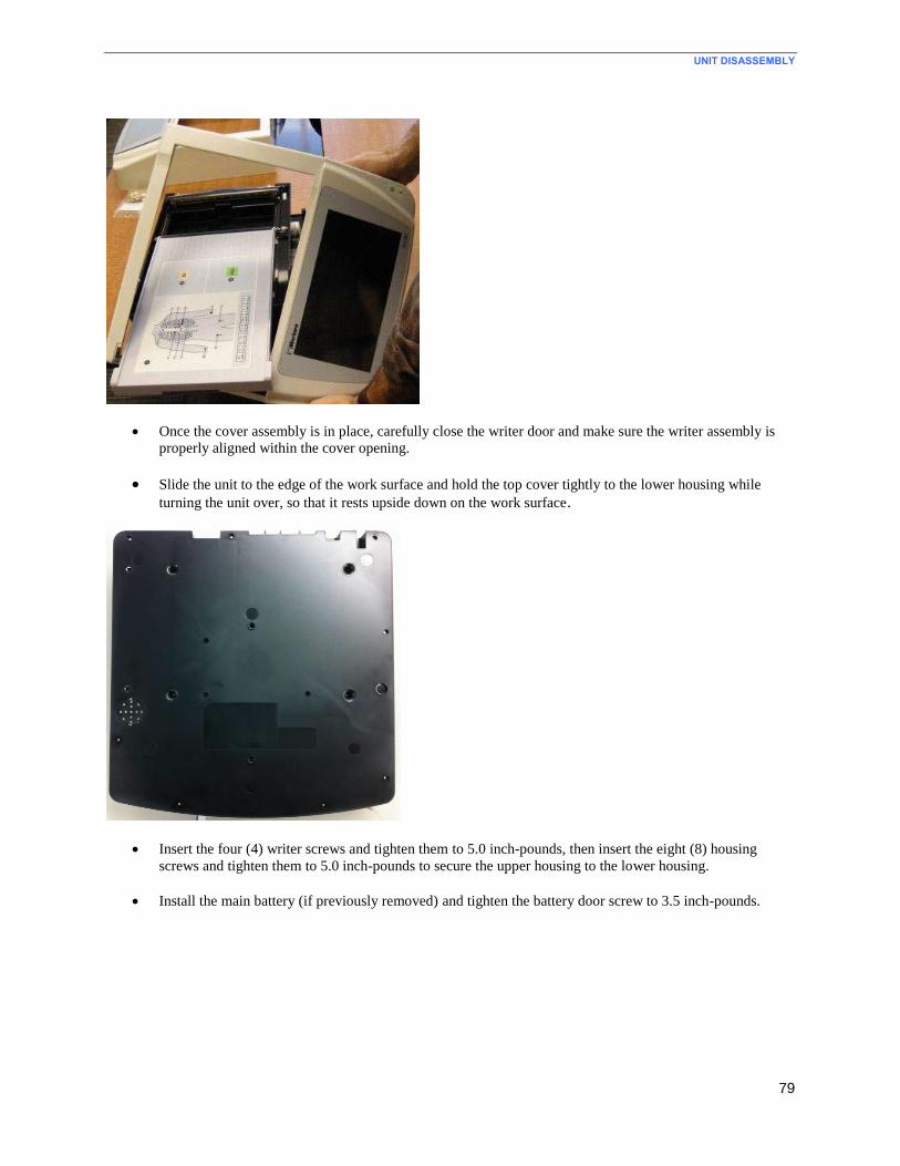
UNIT DISASSEMBLY
79
Once the cover assembly is in place, carefully close the writer door and make sure the writer assembly is
properly aligned within the cover opening.
Slide the unit to the edge of the work surface and hold the top cover tightly to the lower housing while
turning the unit over, so that it rests upside down on the work surface.
Insert the four (4) writer screws and tighten them to 5.0 inch-pounds, then insert the eight (8) housing
screws and tighten them to 5.0 inch-pounds to secure the upper housing to the lower housing.
Install the main battery (if previously removed) and tighten the battery door screw to 3.5 inch-pounds.
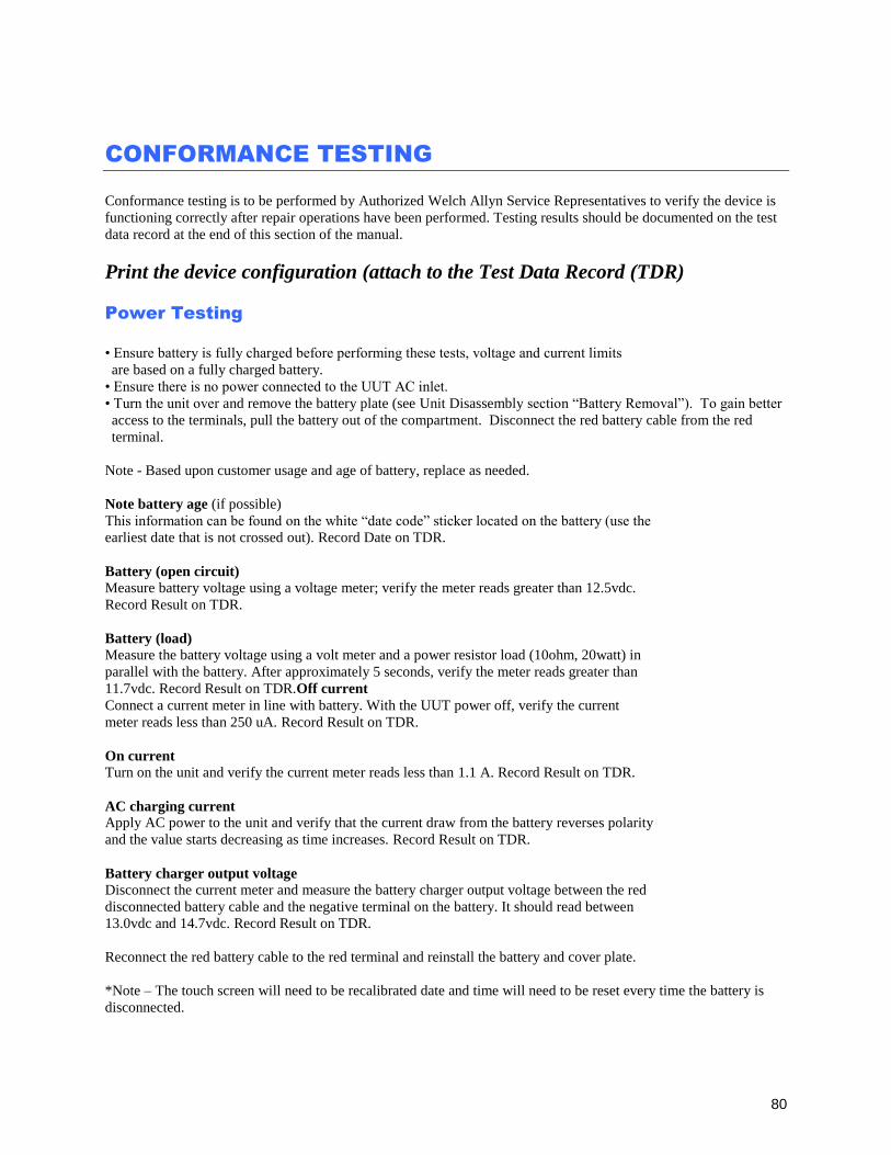
80
CONFORMANCE TESTING
Conformance testing is to be performed by Authorized Welch Allyn Service Representatives to verify the device is
functioning correctly after repair operations have been performed. Testing results should be documented on the test
data record at the end of this section of the manual.
Print the device configuration (attach to the Test Data Record (TDR)
Power Testing
• Ensure battery is fully charged before performing these tests, voltage and current limits
are based on a fully charged battery.
• Ensure there is no power connected to the UUT AC inlet.
• Turn the unit over and remove the battery plate (see Unit Disassembly section “Battery Removal”). To gain better
access to the terminals, pull the battery out of the compartment. Disconnect the red battery cable from the red
terminal.
Note - Based upon customer usage and age of battery, replace as needed.
Note battery age (if possible)
This information can be found on the white “date code” sticker located on the battery (use the
earliest date that is not crossed out). Record Date on TDR.
Battery (open circuit)
Measure battery voltage using a voltage meter; verify the meter reads greater than 12.5vdc.
Record Result on TDR.
Battery (load)
Measure the battery voltage using a volt meter and a power resistor load (10ohm, 20watt) in
parallel with the battery. After approximately 5 seconds, verify the meter reads greater than
11.7vdc. Record Result on TDR.Off current
Connect a current meter in line with battery. With the UUT power off, verify the current
meter reads less than 250 uA. Record Result on TDR.
On current
Turn on the unit and verify the current meter reads less than 1.1 A. Record Result on TDR.
AC charging current
Apply AC power to the unit and verify that the current draw from the battery reverses polarity
and the value starts decreasing as time increases. Record Result on TDR.
Battery charger output voltage
Disconnect the current meter and measure the battery charger output voltage between the red
disconnected battery cable and the negative terminal on the battery. It should read between
13.0vdc and 14.7vdc. Record Result on TDR.
Reconnect the red battery cable to the red terminal and reinstall the battery and cover plate.
*Note – The touch screen will need to be recalibrated date and time will need to be reset every time the battery is
disconnected.
CONFORMANCE TESTING
81
Functional Testing
MAIN SCREEN: (the MAIN SCREEN is displayed when the unit is first turned on)
The LCD will timeout and go dark if there is no ECG or user input. Touch the screen or press the power button to
re-activate.
SERVICE SCREEN:
• To access the SERVICE SCREEN begin at the MAIN SCREEN.
• Press the GEARS icon (lower right)
• Press the ADVANCED icon, then enter the admin password
• Press the SERVICE icon.
CONFIGURATION SCREEN:
• To access the CONFIGURATION SCREEN begin at the MAIN SCREEN.
• Press the GEARS icon (lower right)
• Press the ADVANCED icon, then enter admin password
Battery Status in About Screen
From the MAIN SCREEN press the GEARS icon.
If unit is connected to AC power, disconnect the unit. Enter the About screen from the configuration
menu. Observe the Battery Voltage field over at least 10 minutes. Confirm that the battery voltage
information updates periodically. Record Results on the TDR
Run the unit on battery power for at least 10 minutes and then return to the About screen from the
configuration. View the Battery Voltage information and confirm that the value has updated. Connect
the unit to AC power and observe the field over the next several minutes. Confirm that the field
updates the information as the battery is charging. Record Results on the TDR
AC LED/Display
Connect the AC power cord to the unit and verify that the green AC LED (located directly below the power
button) illuminates continuous.
Press the ON button and verify the text on display is clear and legible and there are no flickering or missing
lines/pixels.
Record Results on the TDR
Auto/Writer Test
From the Service Screen, select the Auto Test icon. Verify the auto test completes one cycle without an
error.
Open and close the writer door to verify smooth operation. Verify that the door unlatches without sticking
and that it latches completely.
From the Service Screen, select the Writer Test icon. Verify that a test page is printed and the writer stops
on the cue mark. The perforation of the paper should line up with the tear edge on the writer. Assure there
are no gaps in the printing and the print darkness is uniform across the entire page (example shown below).
Verify the writer gears do not skip and paper is tracking properly (you may need to print multiple pages to
observe this).
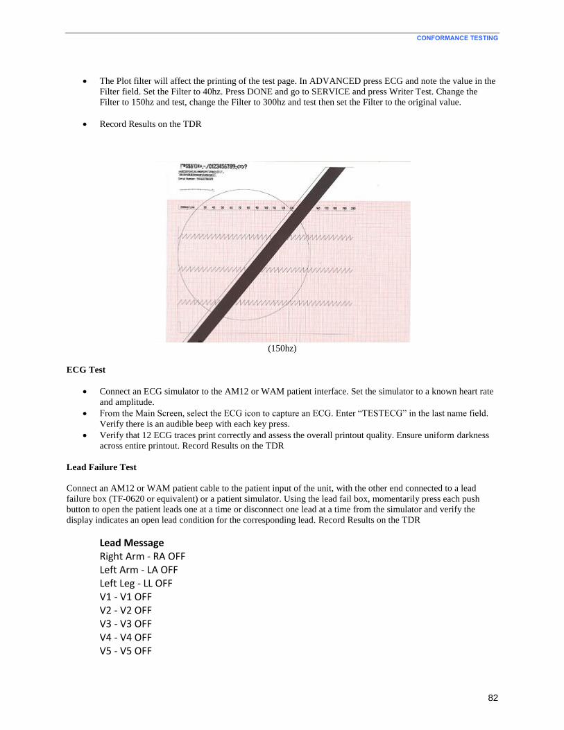
CONFORMANCE TESTING
82
The Plot filter will affect the printing of the test page. In ADVANCED press ECG and note the value in the
Filter field. Set the Filter to 40hz. Press DONE and go to SERVICE and press Writer Test. Change the
Filter to 150hz and test, change the Filter to 300hz and test then set the Filter to the original value.
Record Results on the TDR
(150hz)
ECG Test
Connect an ECG simulator to the AM12 or WAM patient interface. Set the simulator to a known heart rate
and amplitude.
From the Main Screen, select the ECG icon to capture an ECG. Enter “TESTECG” in the last name field.
Verify there is an audible beep with each key press.
Verify that 12 ECG traces print correctly and assess the overall printout quality. Ensure uniform darkness
across entire printout. Record Results on the TDR
Lead Failure Test
Connect an AM12 or WAM patient cable to the patient input of the unit, with the other end connected to a lead
failure box (TF-0620 or equivalent) or a patient simulator. Using the lead fail box, momentarily press each push
button to open the patient leads one at a time or disconnect one lead at a time from the simulator and verify the
display indicates an open lead condition for the corresponding lead. Record Results on the TDR
Lead Message Right Arm - RA OFF Left Arm - LA OFF Left Leg - LL OFF V1 - V1 OFF V2 - V2 OFF V3 - V3 OFF V4 - V4 OFF V5 - V5 OFF

CONFORMANCE TESTING
83
V6 - V6 OFF All Leads off - LEADS OFF
ECG Noise Test
Connect a Shorting Block (TF-0629 or equivalent and lead wire adapters to an AM12 or WAM patient interface.
Connect the patient interface to the unit and set the ECG gain to 20mm/mV. Print a rhythm strip (approx. 1 page).
Verify that no channels have more than 0.5mm of noise as measured by using Welch Allyn thermal paper. (Smallest
grid line = 1mm) Record Results on the TDR
Communication Option Testing (as applicable)
The receiving station for modem, LAN and WLAN transmissions should be running Welch Allyn ELI-Link
software. Refer to the ELI-Link user manual for proper configuration.
Verify successful transmission of all applicable communication options by acquiring ECG records that include the
transmission method in the “Patient Name” field (such as Last Name = USBD) then subsequently transmitting the
ECG record stored to a compatible receiving device. Consult the product user manual if needed to properly
configure the communication settings for each option present on the unit under test.
Successful transmission of the test records can be verified by viewing the ECG records in the unit directory after
transmission and confirming they are marked as “transmitted” (as defined in the product user manual). Record
Results on the TDR
- USB host (USB memory device needed)
- USBD
- Modem
- LAN
- WLAN
CONFORMANCE TESTING
84
Device Cleaning
Clean unit per the instructions provided in the Preventive Maintenance section of the service manual.
Safety Testing
If the cardiograph housing was opened for repair or inspection work, the following safety tests should be performed
in accordance with the IEC 60601-1 or IEC 62353 methods and limits.
The ELI280 is considered a Class 1 Type CF device, intended to only be utilized with the Welch Allyn AM12 or
WAM patient input modules. Defibrillation isolation from the patient is provided by the patient input modules,
which are tested separately as part of the manufacturing process (they are considered non-serviceable devices),
therefore Hi-pot testing is not required for the ELI280 cardiograph.
Earth Leakage
Enclosure Leakage
Non-conductive (fully insulated) chassis testing should be performed utilizing 200 cm2 conductive foil or
equivalent, earth ground on AC input is utilized for functional earth (not safety grounding).
Patient Leakage
Applied part – patient input (utilize Welch Allyn AM12 patient cable)
Patient Auxiliary Current
Applied part – patient input (utilize Welch Allyn AM12 patient cable)
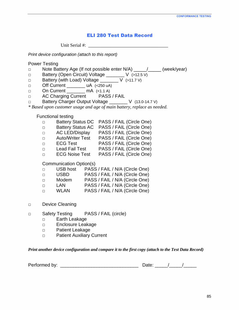
CONFORMANCE TESTING
85
ELI 280 Test Data Record
Unit Serial #: __________________________________
Print device configuration (attach to this report)
Power Testing □ Note Battery Age (If not possible enter N/A) _____/_____ (week/year) □ Battery (Open Circuit) Voltage _______ V (>12.5 V)
□ Battery (with Load) Voltage _______ V (>11.7 V) □ Off Current _______ uA (<250 uA) □ On Current _______ mA (<1.1 A)
□ AC Charging Current PASS / FAIL □ Battery Charger Output Voltage _______ V (13.0-14.7 V) * Based upon customer usage and age of main battery, replace as needed.
Functional testing □ Battery Status DC PASS / FAIL (Circle One) □ Battery Status AC PASS / FAIL (Circle One)
□ AC LED/Display PASS / FAIL (Circle One) □ Auto/Writer Test PASS / FAIL (Circle One) □ ECG Test PASS / FAIL (Circle One)
□ Lead Fail Test PASS / FAIL (Circle One) □ ECG Noise Test PASS / FAIL (Circle One)
Communication Option(s) □ USB host PASS / FAIL / N/A (Circle One) □ USBD PASS / FAIL / N/A (Circle One) □ Modem PASS / FAIL / N/A (Circle One) □ LAN PASS / FAIL / N/A (Circle One) □ WLAN PASS / FAIL / N/A (Circle One)
□ Device Cleaning
□ Safety Testing PASS / FAIL (circle) □ Earth Leakage □ Enclosure Leakage □ Patient Leakage □ Patient Auxiliary Current
Print another device configuration and compare it to the first copy (attach to the Test Data Record)
Performed by: ______________________________ Date: _____/_____/_____
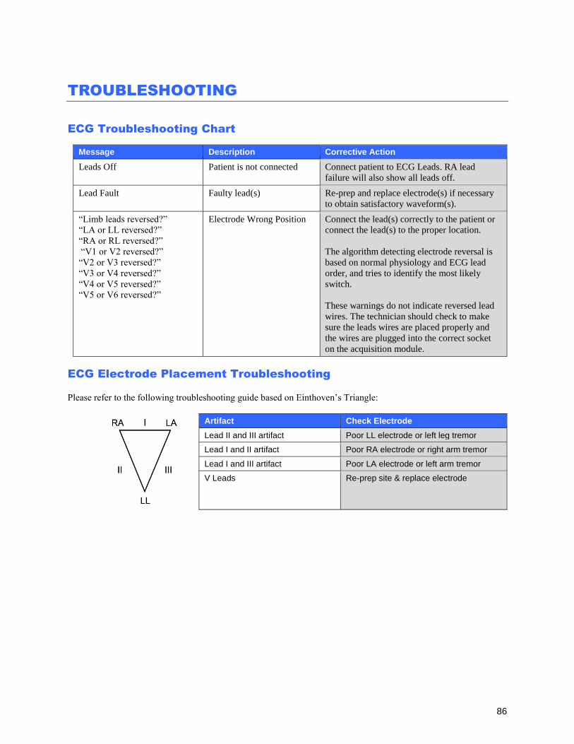
86
TROUBLESHOOTING
ECG Troubleshooting Chart
Message Description Corrective Action
Leads Off Patient is not connected Connect patient to ECG Leads. RA lead
failure will also show all leads off.
Lead Fault Faulty lead(s) Re-prep and replace electrode(s) if necessary
to obtain satisfactory waveform(s).
“Limb leads reversed?”
“LA or LL reversed?”
“RA or RL reversed?”
“V1 or V2 reversed?”
“V2 or V3 reversed?”
“V3 or V4 reversed?”
“V4 or V5 reversed?”
“V5 or V6 reversed?”
Electrode Wrong Position Connect the lead(s) correctly to the patient or
connect the lead(s) to the proper location.
The algorithm detecting electrode reversal is
based on normal physiology and ECG lead
order, and tries to identify the most likely
switch.
These warnings do not indicate reversed lead
wires. The technician should check to make
sure the leads wires are placed properly and
the wires are plugged into the correct socket
on the acquisition module.
ECG Electrode Placement Troubleshooting
Please refer to the following troubleshooting guide based on Einthoven’s Triangle:
Artifact Check Electrode
Lead II and III artifact Poor LL electrode or left leg tremor
Lead I and II artifact Poor RA electrode or right arm tremor
Lead I and III artifact Poor LA electrode or left arm tremor
V Leads Re-prep site & replace electrode
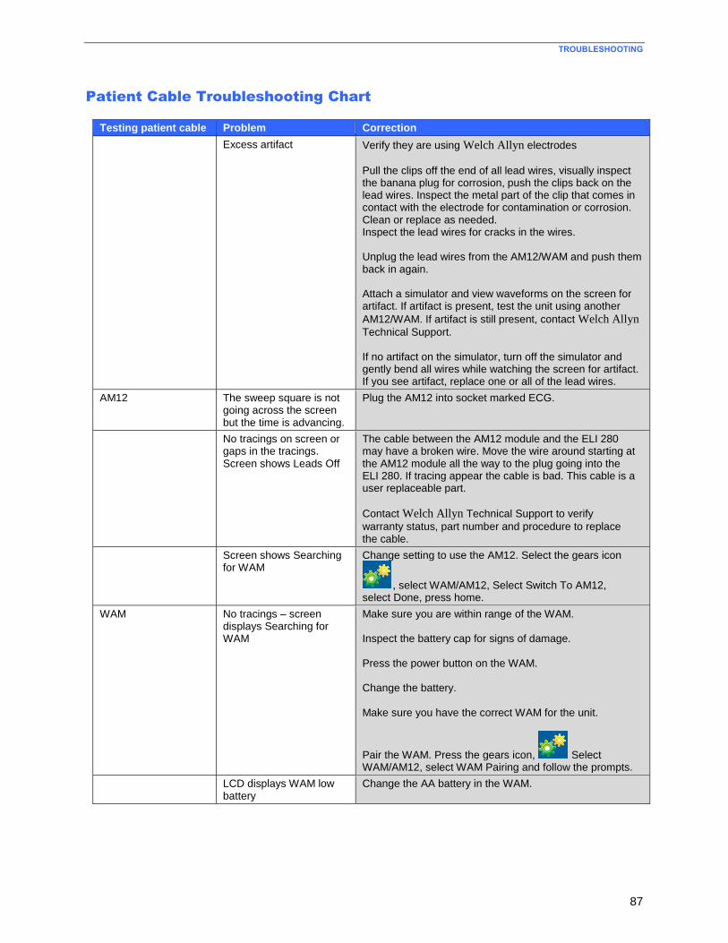
TROUBLESHOOTING
87
Patient Cable Troubleshooting Chart
Testing patient cable Problem Correction
Excess artifact Verify they are using Welch Allyn electrodes
Pull the clips off the end of all lead wires, visually inspect the banana plug for corrosion, push the clips back on the lead wires. Inspect the metal part of the clip that comes in contact with the electrode for contamination or corrosion. Clean or replace as needed. Inspect the lead wires for cracks in the wires. Unplug the lead wires from the AM12/WAM and push them back in again. Attach a simulator and view waveforms on the screen for artifact. If artifact is present, test the unit using another
AM12/WAM. If artifact is still present, contact Welch Allyn
Technical Support. If no artifact on the simulator, turn off the simulator and gently bend all wires while watching the screen for artifact. If you see artifact, replace one or all of the lead wires.
AM12 The sweep square is not going across the screen but the time is advancing.
Plug the AM12 into socket marked ECG.
No tracings on screen or gaps in the tracings. Screen shows Leads Off
The cable between the AM12 module and the ELI 280 may have a broken wire. Move the wire around starting at the AM12 module all the way to the plug going into the ELI 280. If tracing appear the cable is bad. This cable is a user replaceable part.
Contact Welch Allyn Technical Support to verify
warranty status, part number and procedure to replace the cable.
Screen shows Searching for WAM
Change setting to use the AM12. Select the gears icon
, select WAM/AM12, Select Switch To AM12, select Done, press home.
WAM No tracings – screen displays Searching for WAM
Make sure you are within range of the WAM. Inspect the battery cap for signs of damage. Press the power button on the WAM. Change the battery. Make sure you have the correct WAM for the unit.
Pair the WAM. Press the gears icon, Select WAM/AM12, select WAM Pairing and follow the prompts.
LCD displays WAM low battery
Change the AA battery in the WAM.
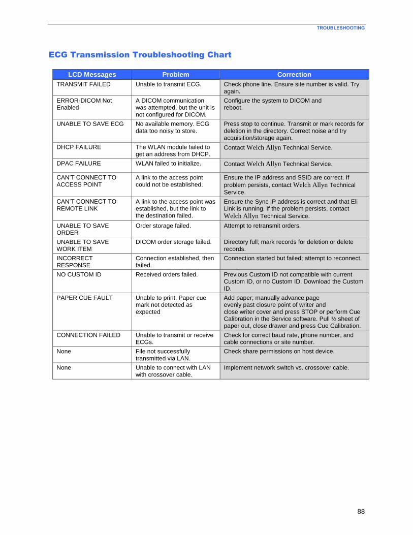
TROUBLESHOOTING
88
ECG Transmission Troubleshooting Chart
LCD Messages Problem Correction
TRANSMIT FAILED Unable to transmit ECG. Check phone line. Ensure site number is valid. Try again.
ERROR-DICOM Not Enabled
A DICOM communication was attempted, but the unit is not configured for DICOM.
Configure the system to DICOM and reboot.
UNABLE TO SAVE ECG No available memory. ECG data too noisy to store.
Press stop to continue. Transmit or mark records for deletion in the directory. Correct noise and try acquisition/storage again.
DHCP FAILURE The WLAN module failed to get an address from DHCP.
Contact Welch Allyn Technical Service.
DPAC FAILURE WLAN failed to initialize. Contact Welch Allyn Technical Service.
CAN’T CONNECT TO ACCESS POINT
A link to the access point could not be established.
Ensure the IP address and SSID are correct. If
problem persists, contact Welch Allyn Technical
Service.
CAN’T CONNECT TO REMOTE LINK
A link to the access point was established, but the link to the destination failed.
Ensure the Sync IP address is correct and that Eli Link is running. If the problem persists, contact
Welch Allyn Technical Service.
UNABLE TO SAVE ORDER
Order storage failed. Attempt to retransmit orders.
UNABLE TO SAVE WORK ITEM
DICOM order storage failed. Directory full; mark records for deletion or delete records.
INCORRECT RESPONSE
Connection established, then failed.
Connection started but failed; attempt to reconnect.
NO CUSTOM ID Received orders failed. Previous Custom ID not compatible with current Custom ID, or no Custom ID. Download the Custom ID.
PAPER CUE FAULT Unable to print. Paper cue mark not detected as expected
Add paper; manually advance page evenly past closure point of writer and close writer cover and press STOP or perform Cue Calibration in the Service software. Pull ½ sheet of paper out, close drawer and press Cue Calibration.
CONNECTION FAILED Unable to transmit or receive ECGs.
Check for correct baud rate, phone number, and cable connections or site number.
None File not successfully transmitted via LAN.
Check share permissions on host device.
None Unable to connect with LAN with crossover cable.
Implement network switch vs. crossover cable.
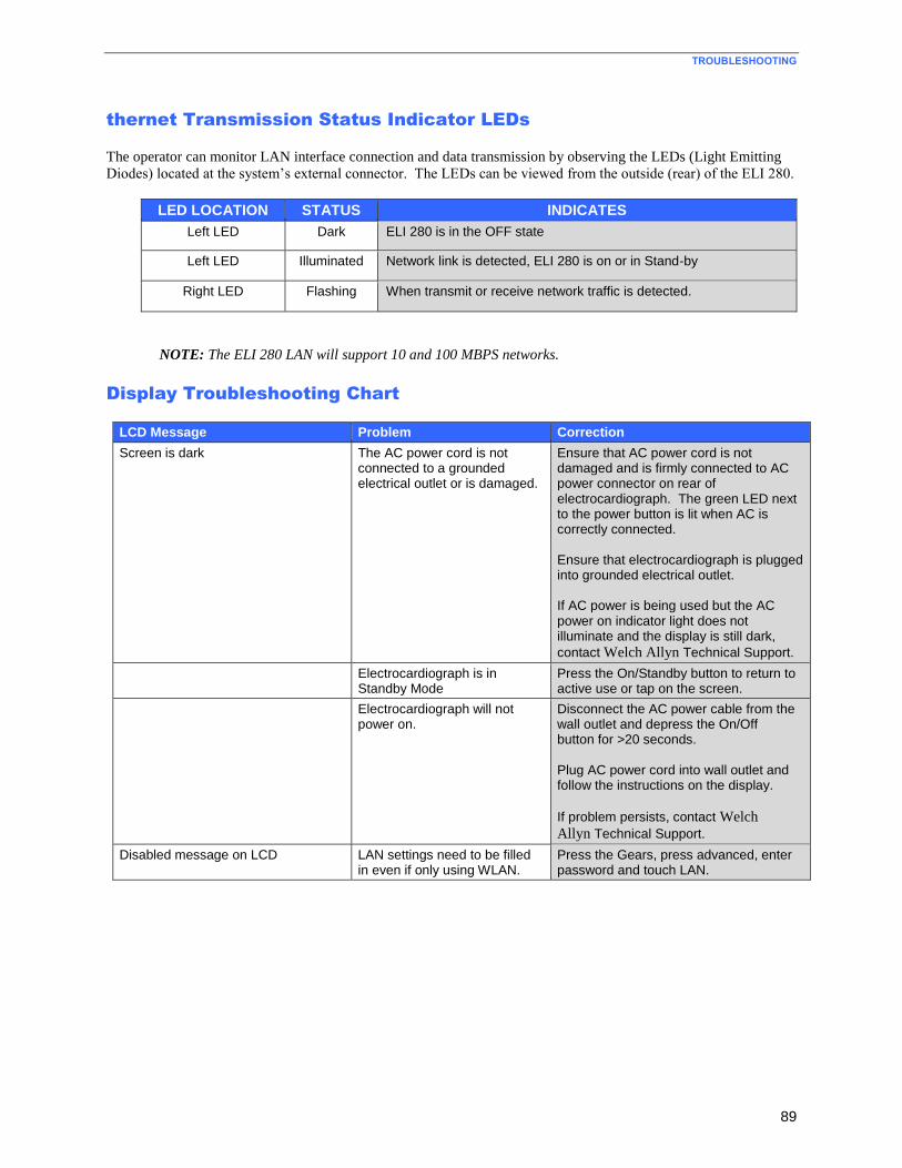
TROUBLESHOOTING
89
thernet Transmission Status Indicator LEDs
The operator can monitor LAN interface connection and data transmission by observing the LEDs (Light Emitting
Diodes) located at the system’s external connector. The LEDs can be viewed from the outside (rear) of the ELI 280.
LED LOCATION STATUS INDICATES
Left LED Dark ELI 280 is in the OFF state
Left LED Illuminated Network link is detected, ELI 280 is on or in Stand-by
Right LED Flashing When transmit or receive network traffic is detected.
NOTE: The ELI 280 LAN will support 10 and 100 MBPS networks.
Display Troubleshooting Chart
LCD Message Problem Correction
Screen is dark The AC power cord is not connected to a grounded electrical outlet or is damaged.
Ensure that AC power cord is not damaged and is firmly connected to AC power connector on rear of electrocardiograph. The green LED next to the power button is lit when AC is correctly connected. Ensure that electrocardiograph is plugged into grounded electrical outlet. If AC power is being used but the AC power on indicator light does not illuminate and the display is still dark,
contact Welch Allyn Technical Support.
Electrocardiograph is in Standby Mode
Press the On/Standby button to return to active use or tap on the screen.
Electrocardiograph will not power on.
Disconnect the AC power cable from the wall outlet and depress the On/Off button for >20 seconds. Plug AC power cord into wall outlet and follow the instructions on the display.
If problem persists, contact Welch
Allyn Technical Support.
Disabled message on LCD LAN settings need to be filled in even if only using WLAN.
Press the Gears, press advanced, enter password and touch LAN.
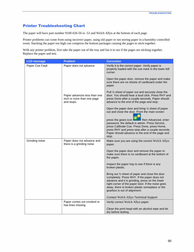
TROUBLESHOOTING
90
Printer Troubleshooting Chart
The paper will have part number 9100-026-50 or -53 and Welch Allyn at the bottom of each page.
Printer problems can come from using incorrect paper, using old paper or not storing paper in a humidity controlled
room. Stacking the paper too high can compress the bottom packages causing the pages to stick together.
With any printer problem, first take the paper out of the tray and fan it to see if the pages are sticking together.
Replace the paper and test.
LCD message Problem Correction
Paper Cue Fault Paper does not advance Paper advances less than one inch or more than one page and stops.
Verify it is the correct paper. Verify paper is properly loaded with the cue mark in the lower left corner. Open the paper door, remove the paper and make sure there are no sheets of cardboard under the paper. Pull ½ sheet of paper out and securely close the door. You should hear a loud click. Press RHY and press Done after a couple seconds. Paper should advance to the end of the page and stop. Open the paper door and bring ½ sheet of paper out and close the door. From the main screen
press the gears icon then Advanced, enter password, the default is admin. Press Service, press Calibrate Cue. Press Done, press Home, press RHY and press stop after a couple seconds. Paper should advance to the end of the page and stop.
Grinding noise Paper does not advance and there is a grinding noise
Make sure you are using the correct Welch Allyn
paper. Open the paper door and remove the paper to make sure there is no cardboard at the bottom of the paper. Inspect the paper tray to see if there is any broken plastic. Bring out ½ sheet of paper and close the door completely. Press RHY. If the paper does not advance and it is grinding, press on the lower right corner of the paper door. If the noise goes away, there is broken plastic someplace or the gearbox is out of alignment.
Contact Welch Allyn Technical Support
Paper comes out crooked or has lines missing
Verify correct Welch Allyn paper.
Clean the print head with an alcohol wipe and let dry before testing.
91
SPECIAL FUNCTIONS
Time Sync
The ELI280 can Time Sync against Eli Link 3.10 or above and E-Scribe 8.15 and above.
Touch the (System Configuration button) from the Real Time Display, touch Date/Time, touch Sync
Date/Time, touch Done when the display shows Time Synchronized.
Testing the WLAN/LAN Settings
To verify connection to the WLAN or LAN touch the (System Configuration button) from the Real Time
Display, touch Network. This will test the WLAN for signal strength and the IP number if WLAN is set to DHCP.
Test WLAN will test for a wireless connection to Eli Link or E-Scribe and download the custom ID. Touch
Done to get back to the setting menu or to go to the Real Time Display.
Test LAN will test for a network connection to Eli Link or E-Scribe and download the custom ID. Touch
Done to get back to the setting menu or to go to the Real Time Display.
Service Menu
The following functions/tests are all in the Service Menu. To access the Service Menu touch the
System Configuration button on the real time screen. Touch Advanced, enter the password, touch
Service.
Cue Sensor Calibration
Cue sensor calibration is required when the cue sensor, writer assembly, or motherboard have been changed as a
result of device servicing or the display shows a paper cue fault.
To calibrate the cue sensor perform the following steps:
Make sure that the paper is not stopped at the perforation line by opening the paper tray, pulling out ½
sheet and closing the paper tray
Touch the Calibrate Cue button.
Auto Test
This button is used to test the flash memory:
Touch Auto Test
If the Flash Test failed contact Welch Allyn Technical Support
SPECIAL FUNCTIONS
92
Change the Device Owner’s Name
To change the device Owner’s Name perform the following steps:
Touch Owner Name and enter the password
Touch the owner name box to bring up the touch keyboard
Enter the name and touch Done when finished
Copy Log Files to a USB Flash Drive
The Log Files may be required by Welch Allyn Technical Support to assist with diagnosing product issues.
To copy log files to a USB flash drive perform the following steps:
Insert a USB flash drive in the USB port on the back of the device
Touch Dump Log Files
This will put log files for Welch Allyn Technical Support as well as battery log files on the USB flash drive
The battery log is in LogBatteryMMYYYY.txt and is viewable by the customer
Copy All ECG Records to a USB Flash Drive
This will not delete the records from the machine. This will not change the status of any status flags. This function
should not be used if the unit is encrypted.
To copy all ECG Records to a USB flash drive perform the following steps:
Insert a USB flash drive in the USB port on the back of the device
Touch Dump Records
Erase All ECG Records
WARNING: The following sequence will permanently erase all ECG records from the device.
To erase all ECG records perform the following steps:
Touch Erase Records
Touch Yes
Writer Test
To test the writer/printhead operation, perform the following steps:
Touch Writer Test
The print on the paper will vary based on the filter set in System.
SPECIAL FUNCTIONS
93
Test Configuration*
*(reset configuration to factory test settings)
WARNING: The following will reset the device to factory default settings. Print a configuration
page before performing this test.
To set the configuration to the factory test settings perform the following steps:
Touch Test Config
Print a configuration page and make changes as needed to get back to your desired settings.
Clear Flags
WARNING: Pressing this button will remove the Print, Transmit and Delete flags (P T X) for all ECG
records stored in the cardiograph.
To clear all ECG status flags perform the following steps:
Touch Clear Flags
Fill Directory
WARNING: This function will copy and create ECG records with new names from existing ECG records
in the cardiograph until the directory is full (requires at least one stored ECG to function).
The new ECG records will not retain any status flag information from the parent record(s).
To completely fill the cardiograph directory for testing purposes perform the following steps:
Touch Fill Directory
Firmware
Used to upgrade the software on the unit.
Config File
Used at the factory only
Options File
Used to upgrade certain purchasable options
SPECIAL FUNCTIONS
94
First Time Boot
WARNING: The following will reset the device to factory default settings. Print a configuration
page before performing this test.
Used at the factory only
IIR on
Only needed if the unit is set for the Chinese language
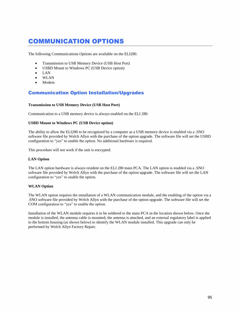
95
COMMUNICATION OPTIONS
The following Communications Options are available on the ELI280.
Transmission to USB Memory Device (USB Host Port)
USBD Mount to Windows PC (USB Device option)
LAN
WLAN
Modem
Communication Option Installation/Upgrades
Transmission to USB Memory Device (USB Host Port)
Communication to a USB memory device is always enabled on the ELI 280.
USBD Mount to Windows PC (USB Device option)
The ability to allow the ELI280 to be recognized by a computer as a USB memory device is enabled via a .SNO
software file provided by Welch Allyn with the purchase of the option upgrade. The software file will set the USBD
configuration to “yes” to enable the option. No additional hardware is required.
This procedure will not work if the unit is encrypted.
LAN Option
The LAN option hardware is always resident on the ELI 280 main PCA. The LAN option is enabled via a .SNO
software file provided by Welch Allyn with the purchase of the option upgrade. The software file will set the LAN
configuration to “yes” to enable the option.
WLAN Option
The WLAN option requires the installation of a WLAN communication module, and the enabling of the option via a
.SNO software file provided by Welch Allyn with the purchase of the option upgrade. The software file will set the
COM configuration to “yes” to enable the option.
Installation of the WLAN module requires it to be soldered to the main PCA in the location shown below. Once the
module is installed, the antenna cable is mounted, the antenna is attached, and an external regulatory label is applied
to the bottom housing (as shown below) to identify the WLAN module installed. This upgrade can only be
performed by Welch Allyn Factory Repair.
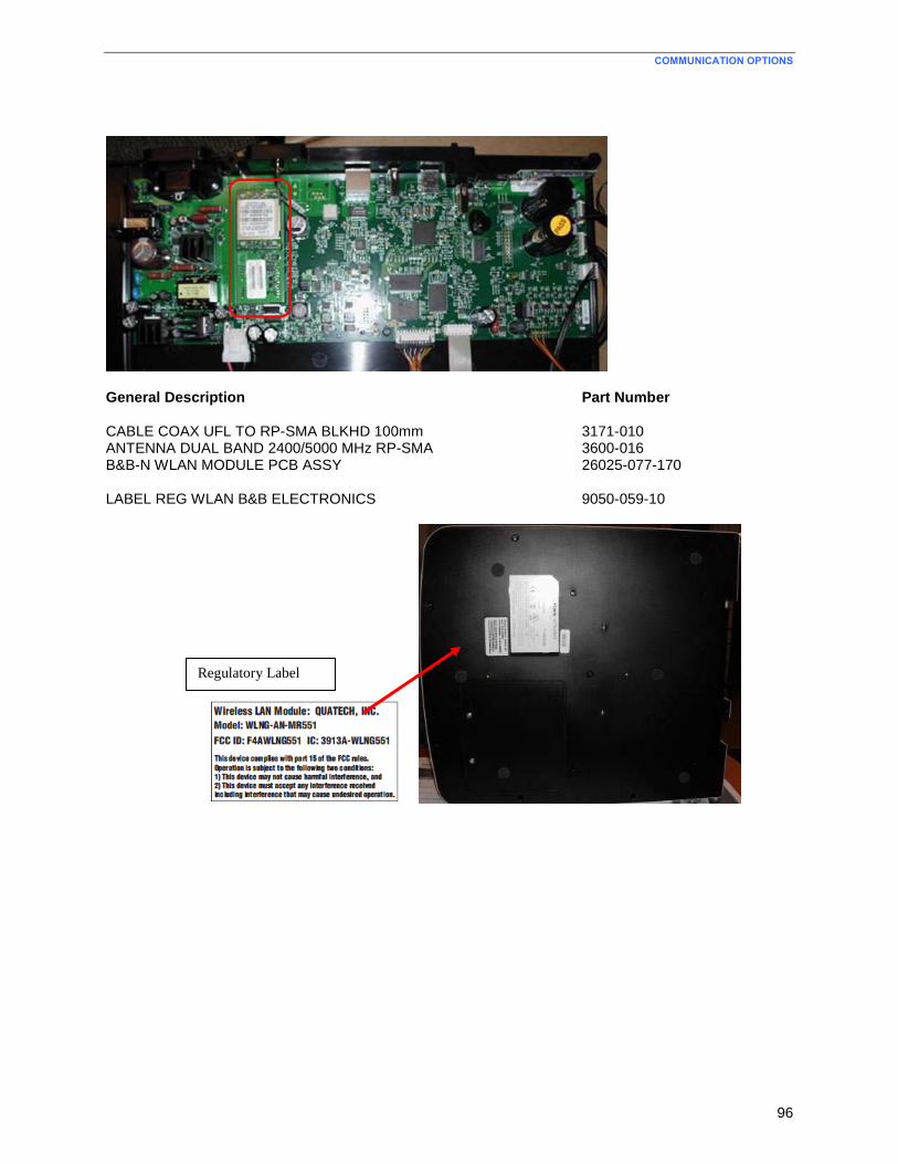
COMMUNICATION OPTIONS
96
General Description Part Number CABLE COAX UFL TO RP-SMA BLKHD 100mm 3171-010 ANTENNA DUAL BAND 2400/5000 MHz RP-SMA 3600-016 B&B-N WLAN MODULE PCB ASSY 26025-077-170 LABEL REG WLAN B&B ELECTRONICS 9050-059-10
Regulatory Label
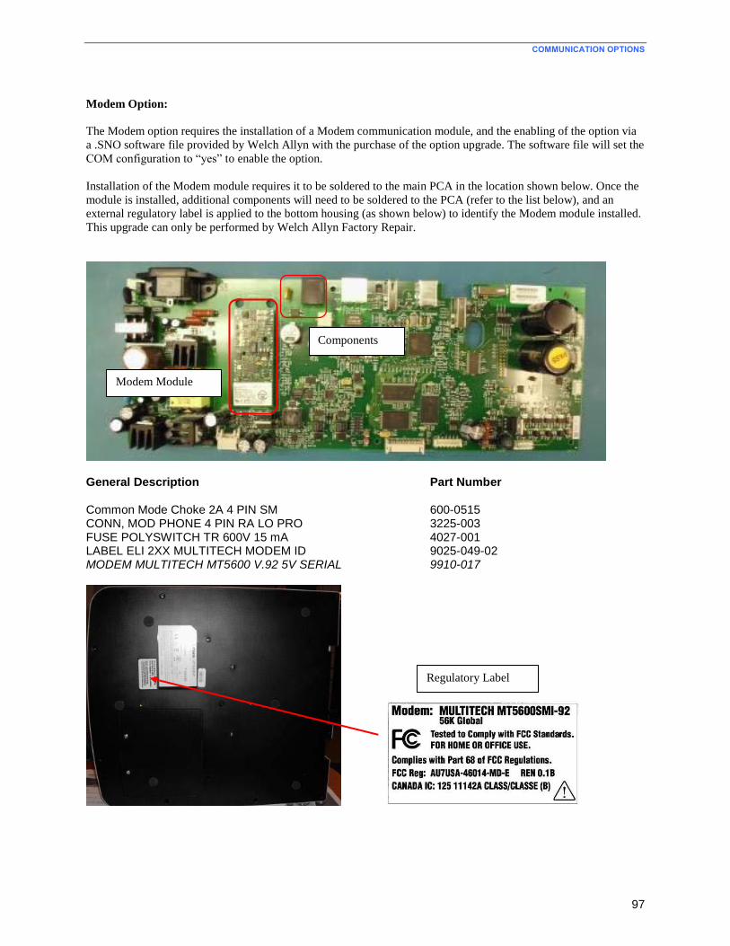
COMMUNICATION OPTIONS
97
Modem Option:
The Modem option requires the installation of a Modem communication module, and the enabling of the option via
a .SNO software file provided by Welch Allyn with the purchase of the option upgrade. The software file will set the
COM configuration to “yes” to enable the option.
Installation of the Modem module requires it to be soldered to the main PCA in the location shown below. Once the
module is installed, additional components will need to be soldered to the PCA (refer to the list below), and an
external regulatory label is applied to the bottom housing (as shown below) to identify the Modem module installed.
This upgrade can only be performed by Welch Allyn Factory Repair.
General Description Part Number Common Mode Choke 2A 4 PIN SM 600-0515 CONN, MOD PHONE 4 PIN RA LO PRO 3225-003 FUSE POLYSWITCH TR 600V 15 mA 4027-001 LABEL ELI 2XX MULTITECH MODEM ID 9025-049-02 MODEM MULTITECH MT5600 V.92 5V SERIAL 9910-017
Modem Module
Components
Regulatory Label