weight estimation of parametrically design of fuel and
TRANSCRIPT

0
Imperial College of Science, Technology and Medicine
Department of Aeronautics
Master Thesis
Weight estimation of parametrically design of fuel and hydraulic systems of a commercial airplane
Francesc Olives
CID: 01660467
Submitted in partial fulfilment of the requirements for the Master’s degree in Industrial Engineering and the Master’s degree in Automotive Engineering as an
exchange student
September 2019
Thesis supervisor: Dr. Errikos Levis

1
Abstract
This project aims to study the feasibility of a program capable of modelling and obtaining the
total weight of the fuel system of commercial aircrafts. Once this program has been created,
focus can be turned to the hydraulic system, with the aim of achieving the same.
In order to achieve this, all the components of both systems are explained, and how these
components work side by side to perform the necessary functions.
A study of the current solutions used has been carried out in order to estimate the mass of the
systems studied (statistical based formulas).
The methodology followed within the project is then explained in order to obtain the code: the
common characteristics, patterns, calculations of the necessary elements and explanation of the
hypotheses and simplifications considered.
Next, how the program works is explained in detail, carried out in Python language, the outputs
that are obtained with its execution, and the limitations of the code. It is clear to see there is not
enough information, or it is confidential, to make a program for the hydraulic system.
After testing the code for the fuel system, analysing the results obtained by the program and
comparing them with the values of the current statistical formulas, the study concludes that
although the approach of a parametric program is interesting from the point of view of flexibility,
we must continue working on and improving the project, as well as collecting real data, to obtain
results that point to the real value of the aircraft.
It is hoped that this project will also serve the reader as a guide to understand how both systems
work and their basic functionalities.

2
Acknowledgments
First and foremost, I would like to thank my supervisor, Dr. Errikos Levis, for offering me the
opportunity to work on this project. In addition, I would like to thank him for his help, guidance
and advice as the project has developed, but above all for the kindness he has shown towards
me.
I would also like to thank my family for their support and for giving me this opportunity to study
abroad and to my aunt Emma for her help.
Finally, to all the great people I have met in London with whom I have spent time and shared
this fantastic experience, and who have kept me motivated during these months I have been
working on the project.

3
Table of contents Abstract .............................................................................................................................. 1
Acknowledgments ............................................................................................................... 2
Table of contents ................................................................................................................. 3
List of tables ........................................................................................................................ 5
List of figures ....................................................................................................................... 6
Introduction ........................................................................................................................ 7
Aims and Objectives ............................................................................................................ 8
Fuel System ......................................................................................................................... 9
Components .............................................................................................................................. 9
Fuel tanks .............................................................................................................................. 9
Fuel pumps .......................................................................................................................... 10
Valves .................................................................................................................................. 11
Lines/conveyance ................................................................................................................ 11
Sealant ................................................................................................................................. 11
Fuel management ............................................................................................................... 11
Auxiliaries ............................................................................................................................ 12
Fuel ...................................................................................................................................... 12
How it works ........................................................................................................................... 12
Feeding ................................................................................................................................ 12
Transfer ............................................................................................................................... 13
Jettison ................................................................................................................................ 14
Refuel/Defuel ...................................................................................................................... 14
Vent/Surge system .............................................................................................................. 15
Fuel quantity indication and level sensing .......................................................................... 15
Hydraulic System ............................................................................................................... 16
Components ............................................................................................................................ 16
Fluid ..................................................................................................................................... 16
Reservoir ............................................................................................................................. 16
Hydraulic pumps.................................................................................................................. 17
Accumulators ...................................................................................................................... 17
Lines..................................................................................................................................... 17
Valves .................................................................................................................................. 17
Filters ................................................................................................................................... 19
Actuators ............................................................................................................................. 19
Power transfer unit (PTU) ................................................................................................... 20
4
Ram air turbine (RAT) .......................................................................................................... 20
How it works ........................................................................................................................... 20
Literature Review .............................................................................................................. 23
Raymer .................................................................................................................................... 23
Torenbeek Method ................................................................................................................. 24
NASA Estimation ..................................................................................................................... 24
Methodology ..................................................................................................................... 26
Fuel system .............................................................................................................................. 26
Layouts ................................................................................................................................ 26
Weight estimation ............................................................................................................... 31
Hypothesis, demonstrations and calculations .................................................................... 31
Program ............................................................................................................................... 38
Hydraulic system ..................................................................................................................... 42
Layout .................................................................................................................................. 42
Surface controls ................................................................................................................... 43
Weight estimation ............................................................................................................... 45
Hypothesis, demonstrations and calculations .................................................................... 46
Program ............................................................................................................................... 50
Results and Analysis .......................................................................................................... 52
Validation of the program ....................................................................................................... 52
Comparison with commercial airplanes .................................................................................. 55
Conclusions ....................................................................................................................... 61
References ........................................................................................................................ 62
Appendices ....................................................................................................................... 65
Appendix A. Fuel components ................................................................................................ 65
Appendix B: EDP (fuel system) ................................................................................................ 67
Appendix C: Electrically driven pumps (fuel system) .............................................................. 68
Appendix D: Electrical valves................................................................................................... 69
Appendix E: Engines families. Thrust and SFC ......................................................................... 70
Appendix F: Hoses and fittings ................................................................................................ 71
Appendix G: Inputs of the fuel program ................................................................................. 73
Appendix H: Hydraulic system of the A310 ............................................................................. 74
Appendix I: EDP (Hydraulic system) ........................................................................................ 75
Appendix J: Hydraulic functions classification ........................................................................ 76
Appendix K: Aircraft layouts .................................................................................................... 77
Appendix L: Layouts estimated by the program ..................................................................... 82

5
List of tables
Table 1: Comparison between the basic layout and its respective modifications. ..................... 54
Table 2: Results of the program for several airplanes and comparison with other methods. ... 56

6
List of figures
Figure 1: Tanks distribution in the Airbus A330 [1]..................................................................... 10
Figure 2: Fuel system layout of the A330. The feed gallery is painted in black [1]. .................... 13
Figure 3: Forward fuel transfer in the A330 [1]. ......................................................................... 14
Figure 4: Refuel function in the A310. Refuelling points are under each wing [5]. .................... 15
Figure 5: Venting lines connected between tanks in the A310 [5]. ............................................ 15
Figure 6: Linear actuator. Extension (A) and retraction (B) [7]. .................................................. 19
Figure 7: Rotatory actuator [7].................................................................................................... 19
Figure 8: Simplest hydraulic circuit with coloured lines according to the function [7]. ............. 20
Figure 9: Hydraulic close circuit [7]. ............................................................................................ 21
Figure 10: ECAM display for the hydraulic system during normal operation in the A320 [9]. ... 22
Figure 11: McDonnell Douglas DC-10-30 .................................................................................... 27
Figure 12: Airbus A340's actual fuel system layout [10]. ............................................................ 28
Figure 13: Boeing B727's actual fuel system layout, with three engines in tail [11]. ................. 28
Figure 14: Airbus A380's actual fuel system layout [15]. ............................................................ 29
Figure 15: APU feeding in the A340 [13]. .................................................................................... 31
Figure 16: Wing's structure [23]. ................................................................................................. 38
Figure 17: Layout estimated by the program. Both axes are in meters. .................................... 40
Figure 18: Outputs of the program. ............................................................................................ 40
Figure 19: Right hydraulic system of a Boeing 777 [7]. ............................................................... 43
Figure 20: Hydraulic systems overview in the Bombardier CRJ100 [27]..................................... 44
Figure 21: Control surfaces of the B727 and the B737 [28]. ....................................................... 45
Figure 22: Necessary inputs to define the surface control "i". ................................................... 47
Figure 23: Position of linear actuators in a wing. ........................................................................ 49
Figure 24: Hydraulic systems obtained by the program. ............................................................ 51
Figure 25: Torenbeek vs. Program weights. ................................................................................ 59
Figure 26: NASA vs. Program weights. ........................................................................................ 59
Figure 27: Raymer vs. Program weights. ..................................................................................... 59
Figure 28: Average (Torenbeek, NASA and Raymer) vs. Program weights. ................................ 60

7
Introduction
Increasing technological improvements over the years have resulted in more tools available for
the design, manufacture and validation in the engineering world. This project has a place within
the first phase. Whilst not so many years ago only simple equations or empirical formulations
were available for the first sketches of a design, now infinite tools are available for a better and
faster design of products and machines.
The idea behind the project therefore is a way to transform these simple formulas (used to
obtain in this case the weight of an airplane system) into a program that provides greater
flexibility and provides extra and personalised complexity to the value of this output (the weight
of the system). Although logically the designed program is far from the very powerful programs
currently used in the industry, the main objective is to transform the current empirical-statistical
approach of estimating the weights of these systems, into a new analytical-systemic approach.
In addition, the driving motivation behind this project, under the supervision of Dr. Errikos Levis,
is to combine the benefits found by this and other similar projects under the same global code
that allows a basic definition of a complete aircraft and its subsystems. Furthermore, the aim is
that in the future, comparisons can be made between the current solutions for the various
subsystems (fuel, hydraulic, pneumatic, and electric) and their fully electric equivalents, as the
industry tends to opt for electrical technology over conventional systems. The aviation sector is
certainly no exception.

8
Aims and Objectives
The primary aim of this project is to successfully develop a parametric program capable of
estimating the number of components and their size, of the fuel system of a conventional
commercial aircraft. Following on from here the intention is to try to apply the same procedure
to the hydraulic system. Using these programs, the weight of the system can be obtained.
The objective is to provide a preliminary tool for the design stage so that given the basic shape
of the airplane and some performance input the tool will provide precise characteristics of the
aircraft. As long as the program is completely parametric, changing any variable will modify the
output and the designer will be able to experiment with some grade of flexibility.
In addition, the program will show in figures the actual layout of both systems, which would give
the user an initial visual idea of the interior of the airplane. These pictures are also parametric
(depending on the inputs) and can vary substantially according to the chosen configuration.
The tool is more focused for derivative and change-based aircrafts due to the fact that actual
data and experimental relations have been used within the code. It could be useful also for an
initial idea for new aircraft, but always bearing in mind that an entire functional analysis of each
part and subsystem will be vital for the success of the project.
Finally, another objective once the program is finished will be validate the reliability of the
program by comparing the weight results with known data, and with results obtained by
methods recognized by the industry.
All the code has been written in Python 2.7 libraries.

9
Fuel System
All powered airplanes require fuel on board to operate their engines. The next two subchapters
will explain, first, the main components that the fuel system contains and, then, how these are
arranged and connected to develop all the functions and requirements needed. The objective
of this chapter is to explain to the reader who is not familiarised with fuel systems so he can
understand clearly the rest of the document. The information will be complemented by some
necessary images. This way, the methodology section will be clear, with no need of clarifying
concepts. However, it will not be explained the innerworkings of the internal components as
they are considered outside of the scope of this project. If the comprehension of the functioning
for any component was needed for the developing of the code, it will be mentioned in the
Methodology section.
Components All the aircrafts share the same components in the fuel system, only varying in the quantity or
the arrangement. In this section, these elements will be explained along with the main purpose
to use each one:
Fuel tanks Their mission is to store the fuel that will fed to the engines without any leakage. A fuel tank can
be rigid, removable, bladder or integral. This project only considers the last ones as they are the
solution used in all commercial airplanes. An integral tank forms a tank as a unit within the
airframe structure, then we have the highest volume of space available with the lowest weight.
This solution is also called wet wings. Therefore, the tanks can be classified according to their
position in the structure (see Figure 1):
- Wing tanks: Are the main tanks of the airplane and they have the biggest capacity. There
is a lot of space in these tanks. In addition, the fuel weight in the wings is used for
offsetting the shear forces and bending moments produced by the wing during the flight
stage. It’s important to know that the wing is normally sealed into separated tanks. With
these separations we can divide the tanks between feed and transfer tanks. The first are
the ones linked with the engines. Moreover, they can have a collector cell where the
boost pumps (explained later) are located.
- Vent/Surge tank: Is a part of the vent system. Connected to the other tanks between
the ventilation pipes, the main function of this empty tanks is equalising the air pressure
(during the different stages of the flight) above the fuel in the tanks to that of the
ambient pressure. The vent tanks have an orifice to the atmosphere. They are also used
to contain the expansion of the fuel due to temperature changes. They are always
located at the end of the wing/tail (never in the center), but some huge aircrafts, like
the A380, can also have extra surge tanks in the middle of the wings.
- Center tank (optional): Some aircrafts incorporate a tank in the fuselage as part of the
adjoining wing box within the section. This gives more capacity of fuel. It has to be
emptied before the wing tanks.
- Rear center/auxiliary tank (optional): Not very common, it is an extra tank behind the
main center tank that is used to extend the range of the aircraft even further. It usually
exists in place of added payload weight.
- Trim tank (optional): Finally, the trim tank is a very common solution in many long
aircrafts for the control of the centre of gravity, transferring fuel from this tank to
forward tanks. It is located in a part of the horizontal stabiliser of the tail.

10
Figure 1: Tanks distribution in the Airbus A330 [1].
Fuel pumps All commercial aircrafts use fuel pumps to feed their engines or to move fuel between the tanks.
All the pumps can be categorized into different technologies but is more important to classify
them into the function that they perform in the fuel system. Nevertheless, a more used
technology is the gear type constant displacement and, overall, the piston type variable
displacement.
- Engine driven pump (EDP): Is one of the most important elements of the fuel system.
Each engine has one fuel pump to deliver clean fuel under high pressure in the exact
rate to the fuel metering device. These types of pumps are mechanical and they are
installed on the engine accessory gear box of the engine.
- Auxiliary/boost: Auxiliary electrical pumps are used to provide fuel under positive
pressure to the engine-driven pump and during the start, when the engine-driven pump
is not yet up to speed for enough fuel delivery. They are also used to back up the engine-
driven pump during take-off and at high altitude to guard against vapor lock.
- Transfer pumps: These electrical pumps are used to move fuel from one tank to another
at medium flow rate and pressure. Some centrifugal fuel pumps operate at more than
one speed, as selected by the pilot, depending on the phase of aircraft operation. Single-
speed fuel pumps are also common. Centrifugal fuel pumps, located in fuel tanks, ensure
positive pressure throughout the fuel system regardless of temperature, altitude, or
flight attitude thus preventing vapor lock.

11
- Jettison pumps: The difference between the previous electrical pumps and these ones
is basically that jettison pumps can give a bigger fuel flow rate and pressure according
to the requirements of this function (explained later).
- Scavenge ejector pumps: These pumps are used to remove condensed water
accumulated in the fuel tanks via the vent system.
The electrical pumps can be powered by alternative or continue current. The most common
is that only the APU pump is DC powered while all the others are AC powered. The APU
pump is a small electrical pump that feeds the APU from one of the feed tanks.
Valves They are many fuel valves uses in aircraft fuel systems. Large aircrafts have numerous valves.
We can use them to shut off the fuel flow or to route the fuel to a desired location. Most
commonly opened and closed type are known by different names related to their location and
function in the fuel system: shutoff, transfer, crossfeed, isolation valves, etc. Check valves are
very regular too. Besides, the system has also a lot of valves for draining (removing accumulated
water from the tanks) and venting, as well as for transferring by gravity between tank
compartments. Although in small aircrafts the manual (mechanical) valves are usual, all the
commercial airplanes use electrical actuators for opening or closing them. These actuators are
type 90º and they work with a continue current. All the valves are electronically automatized
and controlled, although the pilot can change the status manually as well.
Lines/conveyance These components form together the web with which the fuel moves around to arrive where it
is needed (feeding engines, transferring, jettison). The lines are one of the parts that has
improved the most these past years. The progress in material research has been achieved to
substantially reduce the diameter of the fuel lines without increasing the drop losses. In
addition, this makes the hoses flexible (this way they can deal with vibrations). Therefore, the
linear weight of the lines is smaller than in the past. An example of a recent [2] hose is the one
made of a conductive convoluted PTFE tube and a reinforcement. The fittings are fabricated
with stainless steel. Sometimes they have fire protection (fire sleeve cover). Logically, different
options of materials and reinforcements exist depending on the final requirements and
applications.
The diameter of the hose depends on the fuel flow rate that these lines must move. Thus, it
depends on what is connected one particular line.
Inside this group we can also consider the venting piping that independently connects the
venting tank with all the compartments. These tubes are normally rigid.
Sealant This component has the key function of avoiding leaking from the fuel tanks. It is applied along
the geometrical lines that represent the union between the wing structure and the spars and
the ribs. The main supplier of this product is PPG Aerospace [3], that offers technical data of
every different type of sealant.
Fuel management Corresponds to all the equipment necessary to manage and monitor the whole fuel environment
on the aircraft (Fuel Quantity Indicating, FQI, System). Level indicators, sensors, gauges, fuel
management manifolds, are examples of components that belong to this group.

12
Auxiliaries The rest of the fuel system components like the integrated drive generator (IDG) heat exchanger
in each engine, fuel filters, connection ports for refuelling/defueling (normally under the wings),
and so on.
Fuel Even though it is not considered an element in the fuel system, is the main protagonist for which
the system works. Therefore, it has been considered appropriate to indicate the characteristics
which are aimed for an optimal functioning.
Basically, there are two main fuel families: gasoline or AVGAS for the reciprocating engines, and
jet fuel or kerosene for the turbine engines. As the last ones are obviously the ones used in
commercial planes, the properties which are needed in jet fuel are:
- Higher viscosity with much lower volatility and higher boiling points than gasoline.
- More density.
- Less flammable (higher flash point).
- Colourless or straw.
- Use of biocides to kill the microbes that exist due to water impurity.
- 3 types: Jet A, Jet A1 (both have low volatility and low vapor pressure), Jet B (blend of
kerosene and gasoline; for cold weather performance).
How it works Each fuel system must provide an uninterrupted amount of fuel regardless of the aircraft’s
performance.
First of all, the general functions of the fuel system are the following:
- Stores fuel in tanks.
- Controls and monitors the correct quantity and pressure of fuel flow.
- Supplies fuel in the correct quantities to the fuel tanks during refuelling.
- Supplies fuel to the engines and the auxiliary power unit (APU).
- Crossfeed capacity to feed the engines and APU from any tank.
- Circulates fuel to cool the integrated drive generator (IDG).
- Keeps fuel in the outer wing for wing bending and flutter relief.
- Allows fuel jettison for rapid weight reduction.
- Fuel manage system: fuel transference from one tank to another → maintains the
Center of Gravity within limits.
- Fuel system independence.
- Allows the venting of the fuel.
Note that not all aircrafts achieve this functions cause some of them depend on the complexity
or the capacity desired by the manufacturer of each airplane.
Feeding Regardless of the philosophy of each manufacturer in the system layout, the feeding of the
engines works same way (Figure 2). Each engine has connected a high pressure EDP that supplies
fuel to it (not drawn in the figure).
Downstream we have low pressure (LP) shutoff valves, located in each engine’s pylon. The goal
of these valves is to close the feeding of the respective engine in case of fire or failing. Continuing

13
with the feed line path, we find the boost electrical pumps, located in the feed tanks or in
collector cells inside the feed tanks. The transfer tanks can be considered as storage tanks which
are used to keep the feed tanks full. Finally, the right and left sides of the fuel feed line are
connected or divided by an electrical fuel crossfeed valve (X-FEED; that is controlled by two
engines for redundancy [4]). This valve allows an engine or the APU to be supplied from the
opposite side of the fuel line if there is a problem.
The APU works in a similar way, with the LP valve in the APU fuel supply line. With the only
difference being that it does not need an EDP.
Figure 2: Fuel system layout of the A330. The feed gallery is painted in black [1].
The fuel feed sequence is automatically controlled by the system, although the manual control
by the pilot is also possible. Normally, the fuel is emptied from the center of the aircraft to the
tips of the wings, in the following sequence (transferring the fuel to the feed tanks):
- Center tank
- Inner tanks
- Mid tanks
- Outer tanks
Transfer With this function is important to differentiate the aircrafts that allow transferring during flight
phase from the ones that only permit transferring on ground (as a complement for
refuel/defuel). In the first group, transferring during flights allows to compensate bending
moments and equilibrating fuel weight. The transfer piping with all the valves and pumps is
called gallery, and goes along all the spanwise of the airplane. Although the most common is to
have only one gallery, some new big aircrafts like the A380 count with 2 galleries due to the
increase of complexity that it has acquired. In that case, the design of the gallery system means
if there is a failure in one of the galleries, the other can take over and complete the fuel transfer.

14
Another important function that some aircrafts must carry out is the maintaining of the optimal
centre of gravity. To do that, some airplanes possess the trim tank that was explained before: as
the fuel is used during flight, the balance point of the aircraft moves quite significantly. In order
to keep the CofG at the optimum as long as possible, fuel is transferred out of the trim tank into
the other tanks (Figure 3 shows fuel transfer when center tank is not empty, left, and when it is,
right), until eventually is empty. Is important to know that even though during flights the fuel
cannot be transferred from wing tanks to the trim tank.
Finally, the lines used to connect the transfer galleries with the feed line (or gallery) either the
trim tank in this document are called isolation lines. These lines, therefore, include isolation
valves that enable them to connect the different parts.
Jettison This optional functioning (some smaller aircrafts do not have it) consists in two nozzles (with
their respective valves) at the mid or tip position of the trailing edge that dump fuel in case of
emergency to reduce the aircraft’s weight quickly for a safe landing.
Jettison rates can vary widely from one plane to another. Besides, the aircraft may have
dedicated jettison electrical pumps or use the transfer ones (with less fuel flow rate).
Refuel/Defuel The refuel and defuel operations are controlled by panels that are normally located under the
wing or in the side of the fuselage. The main refuel hose from the airport ground is connected
to the refuelling points/couplings under the wing, and all the inlet valves are conveniently
opened to full the tanks. The desired fuel load is preselected on the panel and is distributed with
opposite priority respect to the consumption: from outer to center. In Figure 4 can be observed
how the refuelling uses the galleries explained before to full the tanks.
Figure 3: Forward fuel transfer in the A330 [1].

15
Figure 4: Refuel function in the A310. Refuelling points are under each wing [5].
Vent/Surge system The vent tanks are located, as mentioned before, at the tip of each wing and at a part of the
horizontal stabilizer. The vent system has these main functions, among others:
- Prevents the tank’s overpressure during refuelling.
- Provides additional thermal expansion space for fuel from the main tanks (connected to
the vent tanks by solid piping; see Figure 5).
- In flight they provide positive differential air pressure in the tanks whatever the aircraft
attitude is.
- The vent tank will overflow overboard if it becomes full.
Figure 5: Venting lines connected between tanks in the A310 [5].
Fuel quantity indication and level sensing Provides a feedback to the pilot about how is working the fuel system. The monitoring and
signalling of the fuel level are out of the interest to develop this project.

16
Hydraulic System
Modern large aircraft make use of hydraulic power to develop functions that require elevated
forces or moments. Although in the past all this was accomplished by machines or pneumatic
power, when the airplanes became bigger the hydraulic power came necessary. The advantages
of a hydraulic system are: light weight (important in airplanes), easy installation, and
simplification of inspection and minimum maintenance requirements. Some of the main tasks
that this system carries out are the following:
- To move primary flight controls: ailerons, elevator, stabilizer, rudder and spoilers.
- To move secondary flight controls: flaps, trim controls, speed brakes.
- To extend and retract the main and nose landing gears.
- To control the wheel brakes.
- To steer the landing gear.
- To operate thrust reversers.
So, as with the fuel system, the main components and how the system works will be explained
as follows.
Components In the case of the hydraulic system, the arrangement of components used from one aircraft to
another is very similar. The difference between them is the quantity, which basically depends
on two points: the number of functions that the hydraulic system has to do, and the redundancy
required. Although as a general rule for good design in airplanes, inherent reliability is better
than redundancy [6]. In this section, the main functions of each component will be explained,
but the internal operation of each one is not important for this project, so is not included in this
document. For further information about how they work, reference [7] can be used.
Fluid The main difference between the fuel system and the hydraulic system is that in the second
case, fluid is part of the system, since it is confined. Hydraulic liquid is used to transmit and
distribute forces to various actuators. As these liquids are almost incompressible, the pressure
applied to any part of a confined liquid is transmitted to every other part without loss of force.
Then, the pressure can be distributed through the whole system via the fluid.
The properties needed for a good hydraulic fluid are:
- Viscosity: internal resistance to flow
- Chemical stability
- Flash point (high)
- Fire point
It’s not relevant to this project neither to elaborate in more detail each property nor to examine
the different types of hydraulic fluids in this document. The most famous hydraulic fluid family
is the Skydrol, and further information about its types can be found online [8].
Reservoir This is the tank where an adequate supply of fluid is stored. It supplies the fluid to the pumps
and also replenishes fluid lost through leakage. Furthermore, the reservoir serves as an overflow
basin for excess fluid forced out of the system by thermal expansion, the accumulators, and by
piston and rod displacement. It also provides a place for the fluid to purge itself of air bubbles

17
that may enter the system. Many reservoirs incorporate strainers in the filler neck to prevent
the entry of foreign matter during servicing.
Reservoirs are either pressurized (by air or fluid) or nonpressurized. Commercial airplanes use
pressurized reservoirs due to high altitude they fly.
Hydraulic pumps The pumps are the components that give pressure to the fluid. As in the fuel system, all the
pumps can be categorized into different technologies but the hydraulic system is more useful to
classify by the energy source.
- Engine driven pumps: are the primary pumps in the hydraulic systems. The EDPs operate
whenever the engines operate. The most widely used ones are the variable
displacement piston pumps.
- Electrically driven pumps: also called ACMPs, normally operated on the ground or when
there is high hydraulic system demand. They are also used for emergencies.
- Air driven pumps.
- Hand pumps: Only used in commercial airplanes as a backup unit for one or two
functions.
Accumulators The accumulator is a steel sphere divided into two chambers by a synthetic rubber diaphragm.
The upper chamber contains fluid under pressure, while the lower chamber is charged with
nitrogen or air. The function of an accumulator is to:
- Relieve pressure surges in the hydraulic system caused by the performance of a unit and
the effort of the pump to maintain pressure at a preset level.
- Aid or supplement the power pump when several units are operating at once by
supplying extra power from its accumulated or stored power.
- Store power for the limited operation of a hydraulic unit when the pump is not in use.
- Supply fluid under pressure to compensate for small internal or external (not desired)
leaks that would cause the system to cycle continuously by action of the pressure
switches continually kicking in.
Many aircraft have several accumulators in the hydraulic system. There may be a main system
accumulator and an emergency system accumulator. There may also be auxiliary accumulators
located in various sub-systems.
Lines The same explanation as per the fuel system. The main difference between both systems is the
operating pressure. Thus, the hydraulic conveyance has to be more resistant due to it works at
much higher pressures.
Valves The hydraulic system also has numerous valves to control and guide the fluid in each required
part. In this system we can find more variety of valves compared to the fuel system. All the valves
in commercial airplanes are electrically controlled by solenoid or servo. Following the division
made by the Federal Aviation Administration [7] we can split the valves in 3 big groups. A brief
explanation without entering into great complexity will be given of each type of used valve.

18
Flow control valves
As the name indicates, the objective is to control the speed and/or direction of fluid flow in the
hydraulic system. Within this group we can find:
- Selector valve: this is used to control the direction of movement of the actuator. It
controls the simultaneous flow of hydraulic fluid both into and out of the unit (the
pressure and return lines).
- Check valve: it only allows the fluid to flow in one direction, and blocks it in the opposite
one. Check valves can be an independent component or built in to a component. There
is also a variation of these that have an orifice so the fuel in the opposite direction is
restricted (but not totally blocked). They can be used as a damper and so on.
- Sequence valve: it controls the sequence of an operation between two branches in an
automatic circuit. Basically, they ensure that one actuator doesn’t move before a
previous one has finished. They can be controlled by pressure, mechanically, or by
electric switches.
- Priority valve: This important valve gives priority to the critical subsystems over the
noncritical ones when the airplane has low pressure. The determination of the critical
functions is within its design. Is pre-set to a pressure value. As long as the pressure is
above this value, all subsystems receive pressure. When it drops below this level, the
valve is closed and no fluid flows to the noncritical systems.
- Quick disconnect valves: They are basically valves for maintenance. They allow an
element to be removed, for example a pump, without leakage of fluid. Another option
is to connect a test between them (there are always two of these pumps, one before
the element and another after).
- Hydraulic fuse: Like the electrical fuse, it closes and shuts off the fluid when the flow
passing through the fuse is greater than the pre-set value. It is a safety device. The
difference compared to the electrical one is that the hydraulic fuse automatically resets
itself when the pressure is removed from the supply side.
Pressure control valves
The elevated pressures with which the system works require a means of controlling pressure to
make a safe and efficient operation of fluid power systems.
- Relief valve: It is used to limit the amount of pressure being exerted on a confined liquid.
This is necessary to prevent the failure of a component or rupture of hydraulic lines.
There is a safety element that discharges fluid from the pressure line into a reservoir
return line when the pressure exceeds the pre-set maximum of the valve.
- Pressure reducers: They are used not as a safety element but when a specific function
requires less pressure than the normal system operating pressure. These valves provide
a steady pressure. One example of application is brakes (for the pilot pedal).
Shuttle/shutoff valves
- Shuttle valves: Are used when one function (subsystem) has to be supplied from two
sources: the normal system and the emergency one (that activates only essential
components). In case of failure of the normal system, this valve blocks the entrance of
flow from it and allows the fluid to enter from the emergency one.
- Shutoff valves: Are used to close the flow of fluid to a particular system or component.

19
Filters Used to clean the hydraulic fluid, preventing foreign particles and contaminating substances to
enter into the system.
The hydraulic fluid holds in suspension tiny particles of metal that are deposited during the
normal wear of selector valves, pumps, and other system components. Such minute particles of
metal may damage the units and parts through which they pass if they are not removed by a
filter. The reliability and efficiency of the entire system depends upon adequate filtering.
Filters may be located within the reservoir, in the pressure line, in the return line, or in any other
location. Modern design often uses a filter module that contains several filters and other
components.
Actuators The actuators are the last component inside the circuit. They develop the movement that the
function requires. They transform fluid pressure into mechanical force which can be used to
move an object (like the surface controls). One side of the actuator is attached to the fixed
structure of the aircraft whilst the other is attached to the moving part. They can be single or
double action type, that means that they can produce movement in one direction only or both,
respectively. Commercial airplanes use the second type for faster transitions, and also because
they have the ability to hold a load in position when the fluid is trapped. In airplanes we can find
three types, basically:
- Linear actuators: to move control surfaces or to extend and retract the landing gear
(Figure 6).
- Rotatory actuators: used for example in the nose wheel steering mechanisms. They are
not limited to the 90º pivot arc typical of cylinders. Figure 7 shows how the use of a rack
and a pinion gear provides large rotations in a small space.
- Hydraulic motor: is basically the same as a hydraulic pump except is used to convert
hydraulic energy into mechanical (rotatory). They are used for the activation of trailing
edge flaps, leading edge slats, and stabilizer trim. It’s also part of the Power Transfer
Unit.
Figure 6: Linear actuator. Extension (A) and retraction (B) [7].
Figure 7: Rotatory actuator [7].

20
Power transfer unit (PTU) This component is very important in commercial airplanes. As will be explained in the next
chapter, these aircrafts count with 3 independent hydraulic systems. The PTU is an element that
allows two systems to connect so in the case that one fails (loss of pressure) the other can
develop the functions of the other. The PTU transfers power between them, but not fluid. We
can also have PTUs that transfer power in one direction while others can do it in both.
Basically, the PTU consist of two components: a hydraulic pump and hydraulic motor connected
via a single drive shaft so that power can be transferred between two systems. Notice that
depending on the direction of transfer, each unit works either as a motor or a pump.
Ram air turbine (RAT) Although it is not a component exclusively of the hydraulic system, the RAT is a backup
component installed in the aircraft to provide electrical and hydraulic powers if the primary
sources of power are lost. It is a turbine that can be deployed in the lower part of the aircraft
and operates a hydraulic pump and generator.
How it works The objective of this chapter is to explain how the hydraulic system works to provide fluid to the
different subsystems, but does not cover how each of these functions work. They are all one or
more actuators that using a simple or more complex mechanism, move components.
The easiest way to understand the hydraulic system is to explain how it works with a simple
sketch. After all, the hydraulic system in an airplane is the same as this sketch, but with many
more elements for security and control (already explained above under components) and with
many actuators (functions)
As per the Figure 8, a basic hydraulic system consists of a reservoir, a pump, selector valve and
an actuator. The reservoir supplies hydraulic fluid to the pump, which in turn raises the pressure
to what the system requires (nominal pressure). Each extreme of the actuator can be connected
via the selector valve to the pressure line and the return line to the reservoir. According to the
position of this valve, these connections are exchanged, and the fluid moves in one direction or
another. There is also the option of trapping the fluid, thereby maintaining an intermediate
position of the actuator.
Figure 8: Simplest hydraulic circuit with coloured lines according to the function [7].

21
The open and closed circuits must be differentiated. Although all commercial airplanes operate
with closed circuits, it is important to briefly explain the open circuits to understand the
differences and why it is necessary to have second ones in aircrafts.
In an open circuit the system is not always under pressure and the components are in series.
Whilst none of them are needed, the fluid circulates inside each of the selector valves and
returns to the reservoir. As soon as a subsystem is needed to perform, the valve changes position
and the system becomes pressurized (this takes some time). Only one component can be moved
at a time.
On the other hand, a closed circuit (Figure 9) operates under pressure at all times. This is
achieved through the chosen control. Without going into too much detail and considering
variable displacement pumps (the most commonly used in large airplanes), an internal pump
compensator automatically varies the volume of fluid required, until it reaches almost zero when
the normal operating pressure of the system is reached. In this way, and for all the flow
situations that are required, the nominal pressure is maintained. In addition, the components
(selector valves) are connected in parallel in a way that several sub-functions can be operated
at the same time. Since instant operations are required on airplanes, closed circuits are used.
The use of this system is only limited by the volume flow capacity of the pump. The flow controls
the power required by all subsystems.
Once it is understood how the basic hydraulic system works, the particularities or values with
which the large commercial airplanes work can be explained.
- The current pressure of the hydraulic system is 3000 psi, and 2000 psi in the older
models. The 8000 psi systems are currently being studied. These advances will allow a
reduction in weight and volume of the system in the future as smaller actuators will be
required. The primary objective is that all elements withstand these high pressures
(greater design restrictions).
- Three totally independent hydraulic systems are used, with all the components
explained in each of them, to ensure safe flight operations. Virtually all subfunctions
performed are connected to at least two of the hydraulic systems. The most critical are
connected to the three systems.
▪ The fluid cannot be transferred from one system to another.
- The number of pumps is a compromise between the criticality of the system and the
required power demand. Normally each system consists of an EDP or an electric pump,
although backup units can also be used.
Figure 9: Hydraulic close circuit [7]. The system is continuously pressurized and actuators are arranged in parallel.
22
- All controls are currently fly-by-wire. The pilot sends the signals electronically to the
servos that control the valves, without the use of mechanical links.
During normal operation (Figure 10), each hydraulic system is in charge of how its functions
work. As mentioned previously, it an entire system fails, there are still two other fully functional
systems that can carry out normal activity. [9]
In case of abnormal operation, sufficient tools are available for the system's reliability, in
addition to the redundancy of the systems acting on the same component. These measures can
be to use the electric pumps or even deploy the RAT.
A system can also be connected through the PTU to pressurize another system that has lost the
nominal pressure (damaged pump). On the other hand, if what you have is a leakage of hydraulic
fluid, you must immediately disconnect the PTU and accept that this system has been lost.
Figure 10: ECAM display for the hydraulic system during
normal operation in the A320 [9].

23
Literature Review
Once it was understood how both systems work, and bearing in mind that one of the objectives
of this project is to be able to compare the results obtained with the techniques currently used
for a first estimate of these systems, it was necessary research these techniques and
methodologies.
The main resources available for this purpose are based on simple formulas based on empirical
regressions, statistics, or as percentages of, for example, the maximum take-off weight of the
aircraft (the latter are not considered in this project since they can differ greatly from the real
value). Some of these come from older books whilst others are a little more up to date. In any
case, the main tools found are the following:
Raymer In his book [10] he suggests two methods to approximate the weights of various groups within
the plane. The first is a fairly rough approach based on the various structural groups of the plane.
The second breaks the plane into the different functional groups and applies statistical equations
based on regression analysis. For passenger or cargo aircraft:
𝑊𝑓𝑢𝑒𝑙 𝑠𝑦𝑠𝑡𝑒𝑚 = 2,405 · 𝑉𝑡0,606 ·
1
(1 +𝑉𝑖𝑉𝑡
)· (1 +
𝑉𝑝
𝑉𝑡) · 𝑁𝑡
0,5 (1)
𝑊ℎ𝑦𝑑𝑟𝑎𝑢𝑙𝑖𝑐𝑠 = 0,2673 · 𝑁𝑓 · (𝐿𝑓 + 𝐵𝑤)0,937 (2)
Where:
𝑊𝑓𝑢𝑒𝑙 𝑠𝑦𝑠𝑡𝑒𝑚: Weight of the fuel system (lb).
𝑉𝑡: Total fuel volume (gal).
𝑉𝑖: Integral tanks volume (gal).
𝑉𝑝: Self sealing ′protected′ tanks volume (gal).
𝑁𝑡: Number of fuel tanks.
𝑊ℎ𝑦𝑑𝑟𝑎𝑢𝑙𝑖𝑐𝑠: Weight of the hydraulic system (lb).
𝑁𝑓: Number of functions performed by controls (typically 4 − 7).
𝐿𝑓: Total fuselage length (ft).
𝐵𝑤: Wing span (ft).
Note that, in the case of commercial passenger airplanes, the formula is simplified by not having
sealed protected tanks:
𝑊𝑓𝑢𝑒𝑙 𝑠𝑦𝑠𝑡𝑒𝑚 = 2,405 · 𝑉𝑡0,606 ·
1
2· 𝑁𝑡
0,5 (3)

24
Torenbeek Method In 1982 the author Egbert Torenbeek put forward various formulas to estimate the weight of
the propulsion group [11]. Of these formulas, the one relating to the fuel system stands out,
which according to the author is composed of:
- Fuel tanks and sealing
- Pumps, collector tanks and plumbing
- Distribution and filling system
- Fuel dump system (if used)
The equation in question for commercial aircraft with integral tanks is as follows (in metric units):
𝑊𝑓𝑢𝑒𝑙 𝑠𝑦𝑠𝑡𝑒𝑚 = 36,3 · (𝑁𝑒𝑛𝑔 + 𝑁𝑓𝑡 − 1) + 4,366 · 𝑁𝑓𝑡0,5 · 𝑉𝑓𝑡
0,333 (4)
Where:
𝑊𝑓𝑢𝑒𝑙 𝑠𝑦𝑠𝑡𝑒𝑚: Weight of the fuel system (kg).
𝑁𝑒𝑛𝑔: Number of engines.
𝑁𝑓𝑡: Number of fuel tanks.
𝑉𝑓𝑡: Total fuel tank volume (liters).
The author also indicates that the number of tanks must be greater than or equal to the number of engines.
As regards the rest of the systems such as hydraulic, electric or pneumatic, in the book only a few ratios appear to obtain a very basic and not very precise approximation of the weights, so they are not of interest in this study.
NASA Estimation NASA proposes in the study ‘The Flight Optimization System Weights Estimation Method’ [12]
to use the following formulas to calculate the weight of the fuel and hydraulic subsystems in the
case of commercial aircraft:
𝑊𝑓𝑢𝑒𝑙 𝑠𝑦𝑠𝑡𝑒𝑚 = 1,07 · 𝑊𝑓𝑢𝑒𝑙 𝑐𝑎𝑝0,58 · 𝑁𝑒𝑛𝑔
0,43 · 𝑉𝑚𝑎𝑥0,34 (5)
𝑊ℎ𝑦𝑑 = 0,57 · (𝐹𝑃𝐴 + 0,27 · 𝑊𝐴) · (1 + 0,03 · 𝑁𝑒𝑛𝑔
𝑤 + 0,05 · 𝑁𝑒𝑛𝑔𝑓
) · (3000
𝐻𝑝𝑟𝑒𝑠𝑠)
0,35
· (1 + 0,04 · 𝑆𝑊𝑃𝑣𝑎𝑟) · 𝑉𝑚𝑎𝑥0,33
(6)
Where:
𝑊𝑓𝑢𝑒𝑙 𝑠𝑦𝑠𝑡𝑒𝑚: Weight of the fuel system (lb).
𝑊ℎ𝑦𝑑: Weight of the hydraulic system (lb).
𝑊𝑓𝑢𝑒𝑙 𝑐𝑎𝑝: Aircraft maximum fuel capacity (lb).

25
𝑁𝑒𝑛𝑔: Number of engines.
𝑉𝑚𝑎𝑥: Maximum Mach number.
𝐹𝑃𝐴: Fuselage planform area (ft2).
𝑊𝐴: Reference wing area (ft2).
𝑁𝑒𝑛𝑔𝑤 : Number of engines on wings.
𝑁𝑒𝑛𝑔𝑓
: Number of engines on fuselage.
𝐻𝑝𝑟𝑒𝑠𝑠: Hydraulic system pressure (psi). The default value is 3000.
𝑆𝑊𝑃𝑣𝑎𝑟: Wing variable sweep weight penalty factor ranging from 0 to 1.
These equations are two of many within NASA's own FLOPS software, and are more modern than those of Torenbeek and Raymer, in addition to being based on a more updated data set. Surprisingly, on the other hand, is the difference in variables used in the NASA methodology to estimate fuel and hydraulic systems (3 versus 7).
As it can be seen, these equations (of the three methods) only depend on a few variables and are different from one another, so the result varies widely if one of the parameters varies. This project, therefore, tries to reduce part of this variance with much more flexible inputs that really differentiate one aircraft from another.

26
Methodology
Once understood how the fuel and hydraulic systems work, it will be explained all the work
further from the information by itself which, in a certain manner, englobes the written code.
From the personalisation of the fuel system (available layouts at the moment), the detailed
study for modelling each main component, to arrive to how the program actually works. Besides,
this part displays all of the different considered hypothesis in their respective sections.
For a better comprehension for the reader, it has been decided to divide this section into two
big blocks: the fuel system and the hydraulic system.
Fuel system Initially, the main objective of the project was to design a program capable of modelling the fuel
system of commercial aircraft.
Layouts The essential part to carry out this project was to research as much information as possible with
the aim of learning how the fuel system works inside. To do so, the key parts were the layouts
or schemes of different aircrafts, the pilot manuals available in the web, and even the forums or
own pilot channels of the commercial airplanes. With all of this, it was intended to detect a
common construction pattern, or some basic rules for specific components, between all the
available aircrafts.
The two bigger difficulties which were found in this phase were: on the one hand (and constantly
during the whole project), the almost impossible chance of finding official material to explain
how this systems work in detail; and on the other hand, to stablish a common logic when writing
the code which will englobe the maximum amount of characteristics which are observed when
the layouts between the main market companies are compared. These differences are even
noticeable between Airbus and Boeing, the two big leaders of the sector.
To gather all of this information models from these companies were studied: Airbus, Boeing,
McDonnell Douglas, Fokker, Embraer y Canadair-Bombardier. The more fruitful that was
obtained was from the Airbus families, with a lot more official information. While, for example,
the planes of the direct competition Boeing, have been studied by non-official mediums.
As the different layouts of each aircraft were observed, they were classified and the different
used components were counted, with the aim of finding patterns to posteriorly writing the code.
The result of part of this classification can be seen in the Appendix A.
After this introduction the different options which can be chosen in each sector of the fuel
system are broken up.
Tanks
The integral fuel tanks, each one of them and their function already explained, represent a look
in the space where most of the elements in the fuel system are placed. In this subsection it is
only important to mention that the global complexity of the system increases if there is a bigger
amount of these tanks. Is very different, for example, to have just one space (besides ventilation
tank) in each wing than having some of them, adding weight but increasing the flexibility and
reliability of the system.

27
Is important to underly that the fuel tanks do not include all the available volume of the wings.
These are delimited by two structural elements, the front and the rear spar, as it necessary to
leave space in the Leading Edge and the Trailing Edge for control surfaces and their mechanisms.
The number of tanks (not including the ventilation ones) right now can oscillate from 3, for
example in the B727, to 11, as the A380. Both the central tank as the compensation tail tank are
always unique, therefore if a plane has more tanks it is always due to the compartmentalisation
of the wings.
Feeding
The fundamental part of the alimentation system is to indicate the number of engines which
need to be fed and their position. This basically stablishes the complexity of the alimentation
conducts. The typical locations are two: under the wings in specific percentage of the spanwise,
or in the tail. Normally one or the other configuration is chosen, however, a joint solution can
also happen (Figure 11).
Figure 11: McDonnell Douglas DC-10-30 with two engines under wings and a central one in tail [Source: United Airlines].
From here each engine needs a supply tank. In the case of an aircraft with an engine in the
central tail, this engine feeds of two fuel tanks in the wings (which can be shared with two
symmetrical engines) or from the central tank (solution adapted from the Boeing 727). Both
solutions are chosen with the aim of maintaining the symmetry of the system.
Finally, the location of the supply lines depends on the predominance of the engines: if these
are located under the wings, we have the conducts next to the front spar; if they are found in
the tail, we have them next to the rear spar. In any case, this is just for the making of and
installation and do not involve any difference in the components besides of an almost null
variability in the length of the conducts. Thus, the front spar as the place of travel has been
chosen arbitrarily for the program, as it represents almost all plane designs.
These explained points can be seen in Figure 12 and Figure 13. The A340 is a somewhat special
plane since both engines in same wing are feed by the same tank. However, each engine has an
own collector cell inside this tank. This is due that the A340 uses exactly the same layout that
the A330, with two extra engines. They are also observed the valves which allow crossfeeding
(“X FEED” in the Figure 12) between the engines and the feed pumps. [13] [14]

28
Figure 12: Airbus A340's actual fuel system layout [13].
Figure 13: Boeing B727's actual fuel system layout, with three engines in tail [14]. The venting pipes can also be observed.

29
Transfer
The complexity of the transference system lays on basically the number of fuel tanks or the
divisions it has. Its function, as its name indicates and it has been explained before, is that of
moving the fuel to the required places. Even though the usual is using just one gallery, some
planes with great wingspan are appearing which have two, as it is the case with the studied
Airbus A380 (Figure 14).
Figure 14: Airbus A380's actual fuel system layout [15]. Both galleries (aft and forward) can be observed in addition to the 11 fuel tanks that the aircraft has.
To keep explaining the elements, it is going to be used a scheme of the A380, as is more complex
than the average, but useful to visualise the connexions between galleries and tanks. In the
figure, valves are represented with a circle and pumps with a square. In general terms, this
galleries are connected with the tanks this way: if is a transference tank, this has connected the
valve and an electric pump to receive and send fuel wherever is necessary; if it is a supply tank,
it has connected just one valve to the gallery to receive fuel (it does not , logically, extract fuel
from the supply tanks).
In addition, the last exterior tank (outer) neither has a pump. However, at the same time is
connected with its interior by a floodgate shaped valve to transfer fuel by using gravity.

30
This gallery is normally located on the opposite side of the feeding gallery. Therefore, generally
located in the rear spar. In the case of relying on two galleries, the forward gallery is located in
the medium zone.
In airplanes with trim tank in tail, this one has logically valves for the filling (as explained) and
pumps to make fuel transfer and control the CofG. The number of these components depends
on the aircraft size and they are connected to the transfer gallery(ies) through a pipe placed in
longitudinal direction (at the center of the fuselage).
Refuel/defuel
The filling and emptying options of the fuel are achieved basically by always connecting the
refuelling points (which are in themselves valves) explained before through the conducts with
the transference gallery.
Isolation
The two galleries from before, the supply and the transference ones, are connected between
them with valves in the middle. Therefore, in this project it was decided to name them isolation
lines. These conducts are also orientated in a longitudinal direction, located between both wings
of the plane. Their function is to be able to jointly use both galleries in emergency situations or,
for example, for the defueling, when the boost pumps are used to guide the fuel to the
transference gallery.
Jettison
If the plane has been designed to be able to use this function, two ejectors are placed in the
wings (one on each side) connected to the transference gallery. These ejectors can be found in
the half (solution adopted by Airbus) or in the tips (Boeing) of the wings. These ejectors can be
considered like a valve.
Auxiliary Power Unit (APU)
The APU is found almost always at the end of the tail. This is like this because is an unused space
in the central line, it has fire protection, and sometimes it does not need of an extra piping. Its
supply is achieved, normally, by extracting fuel directly from one of the supply tanks/cells of one
of the engines. A pump of a smaller size, which works with DC, extracts fuel and directs it to the
APU, which has a LP valve similar to the one in the engines.
It is important to mention that two alternatives to move the fuel to the device have been
observed. The first consists on an independent line just used for the APU; while the second
solution, just available in the case of having a tank in the tail, uses this same line for the end. In
the fist more conduct is used while in the second more valves, for the coupling and decoupling.
Besides, in the case of having a compensation tank, the APU can also be fed from this one if this
line is shared. The reliability is here the criteria that the designers use. In the next Figure 15 it
can be seen all the options talked above:
31
Figure 15: APU feeding in the A340 [13]. From left to right: using the collector cell and the APU pump; using the feeding line (and boost pumps); during the
refuelling of the trim tank; and from the trim tank.
Weight estimation Once the different layouts have been observed and studied, before writing the code was needed
to break up in subgroups the total mass of the fuel system. This way is easier to analyse the
components which can be calculated, which had to be estimated and which others could not be
obtained. Thus, and in junction with how the fuel system works, the total mass of it is:
𝑊𝑓𝑢𝑒𝑙 𝑠𝑦𝑠 = 𝑊𝑙𝑖𝑛𝑒𝑠 + 𝑊𝑝𝑢𝑚𝑝𝑠 + 𝑊𝑣𝑎𝑙𝑣𝑒𝑠 + 𝑊𝑠𝑒𝑎𝑙𝑎𝑛𝑡 + 𝑊𝑓𝑢𝑒𝑙 𝑚𝑎𝑛𝑎𝑔𝑒𝑚𝑒𝑛𝑡 + 𝑊𝑎𝑢𝑥 (7)
Where:
𝑊𝑓𝑢𝑒𝑙 𝑠𝑦𝑠: Weight of the fuel system.
𝑊𝑙𝑖𝑛𝑒𝑠: Weight of the fuel piping and the vent piping.
𝑊𝑝𝑢𝑚𝑝𝑠: Weight of the EDP, the electrical and the scavenge pumps.
𝑊𝑣𝑎𝑙𝑣𝑒𝑠: Weight of the valves (all types).
𝑊𝑠𝑒𝑎𝑙𝑎𝑛𝑡: Weight of required sealant for the integral tanks.
𝑊𝑓𝑢𝑒𝑙 𝑚𝑎𝑛𝑎𝑔𝑒𝑚𝑒𝑛𝑡: Weight of all the components for the fuel management.
𝑊𝑎𝑢𝑥𝑖𝑙𝑎𝑟𝑖𝑒𝑠: Weight of all the extra components.
Hypothesis, demonstrations and calculations In this section they are presented all the hypothesis applied to the program due to the data
found and analysed in the web, the information read, or due to previous assumptions made in
other researches.
In addition, on this document appear the conclusions about commercial components as valves,
pumps or hoses. The information has been extracted from catalogues and manufacturers. The

32
leader company for aerospace components is EATON [16], from where has been obtained a big
part of the data.
Fuel capacity
This section contains the formulas used to calculate the maximum volume available of fuel
according to the selected layout.
Equation for defining a symmetric unitary NACA airfoil [17] (upper part):
𝑦𝑡 = 5 · 𝑡 · [0,2969 · √𝑥 − 0,1260 · 𝑥 − 0,3516 · 𝑥2 + 0,2843 · 𝑥3 − 0,1015 · 𝑥4] (8)
Where:
𝑦𝑡: Half thickness at a given value of x, from centerline to surface (m).
𝑥: Position along the chord (0 ÷ 1).
𝑡: Maximum thickness as a fraction of the chord (0 ÷ 1).
Note that t gives the last two digits in the NACA 4-digit denomination divided by 100.
The length of the chord depending on the span position:
𝑐(𝑦) = (1 − 2 · (1 − 𝜆) ·𝑦
𝑏) · 𝑐𝑟 (9)
Where:
𝑐(𝑦): Length of the chord (m).
𝑏: Span (m).
𝑦: Position along the span (0 ÷ b/2 ).
𝜆: Taper ratio
𝑐𝑟: Root chord, in the centerline (m).
Hypothesis
- The total span of the tanks is 98% of the real span (for the tip wings).
- Wing fuel tanks are 85% usable [10] measured from the external skin surface while
center tanks are idealized as cubic and are 92% usable (space for the components).
- 5% of the wing tanks is for the vent tanks [10].
- The volume in the tail tank can be calculated equal as the wings, but extending until the
root (the aircraft does not have in the tail another cubic part like the center tank).
Studies say [18] that thickness to chord ratio in tail is approximately 2% lower than in
wings.
- In the tail (these hypotheses are supplied by the observations in the drawings of the trim
tanks and by comparing the first results with the real size of the airplane’s tanks):
o Tail’s rear spar = Wing’s rear spar - 5%
o The total span of the tanks is 60% of the real span approximately.
The generic volume of a tank is, then:
𝑉𝑖−𝑡𝑎𝑛𝑘 = %𝑢𝑠𝑎𝑏𝑙𝑒 · (1 − %𝑣𝑒𝑛𝑡) · 𝑤𝑖𝑑𝑡ℎ · 𝐴𝑤𝑖𝑑𝑡ℎ−𝑠𝑒𝑐𝑡𝑖𝑜𝑛 (10)

33
The volume in both wings is, then (not considering the space of the center tank):
𝑉𝑤𝑖𝑛𝑔𝑠 = 0,85 · 0,95 · 2 · ∫ 𝑐(𝑦)2 · (2 · ∫ 𝑦𝑡(𝑥) · 𝑑𝑥
𝑟𝑒𝑎𝑟 𝑠𝑝𝑎𝑟
𝑓𝑟𝑜𝑛𝑡 𝑠𝑝𝑎𝑟
)0,98·𝑏/2
𝐷/2
· 𝑑𝑦 (11)
The generic volume of center tank, is exists:
𝑉𝑐𝑒𝑛𝑡𝑒𝑟 𝑡𝑎𝑛𝑘 = 0,92 · 𝑐(𝐷/2) · (𝑟𝑒𝑎𝑟 𝑠𝑝𝑎𝑟 − 𝑓𝑟𝑜𝑛𝑡 𝑠𝑝𝑎𝑟) · 𝑡𝐷/2 · 𝐷 (12)
The volume of the trim tank in the tail, is exists:
𝑉𝑡𝑎𝑖𝑙 = 0,85 · 0,95 · 2 · ∫ 𝑐(𝑦)2 · (2 · ∫ 𝑦𝑡(𝑥) · 𝑑𝑥𝑟𝑒𝑎𝑟 𝑠𝑝𝑎𝑟−0.05
𝑓𝑟𝑜𝑛𝑡 𝑠𝑝𝑎𝑟
)0,6·𝑏/2
0
· 𝑑𝑦 (13)
Where:
𝑏: Spanwise (m).
𝐷: Diameter of the fuselage (m).
𝑐(𝐷/2): Chord where wings join the fuselage (m).
𝑡𝐷/2: Thickness where wings join the fuselage (m).
Layout, number of components
In this section, the patterns which have been detected by studying the different layouts/manuals
of commercial planes are listed and using the information gathered from the moment the
project was started. Thus, most of the conclusions in this research are personal to the writer. If
they are not original conclusions, these will be properly referenced.
1. Each engine uses one, and just one, EDP. The reference [19] is the only scheme found
where the pumps in the engines are drawn.
2. At the same time, each engine (or its respective EDP) is feed by two electric boost pumps
which are generally located in the feed tank. In any case, it was included to the program
the option of added electric boost pumps.
a. Sometimes these pumps have mounted a sequence valve that allows feeding by
gravity (case of the Airbus A320 [4]).
3. Each engine is fed by an independent fuel tank. The case of the central engine in the tail
is an exception, as it is fed with two tanks (one on each wing).
4. The APU is also fed by one of the tanks talked about above (it does not have an own
tank) or with a compensation tank if it is connected to it.
5. Each engine, and also the APU, count on just one Low Pressure valve to close the feeding
in case of emergency.
6. For planes with 4 engines under the wing, the feeding can be independent or not; this
is, each engine has their own feeding line and the crossfeed is permitted between all of
them or each wing has its own line and there is just crosfeed between sides. In any way,
in the layouts found, just independent feeding was seen. This implies:
a. N crosfeed valves for N engines.

34
7. Regarding the fuel transference:
a. The feeding tanks have just one entrance valve per gallery.
b. The transference tanks have a valve and an electric pump on each gallery.
c. If the plane has a central tank, it tends to have two electric pumps.
d. The outer tank (the transference tank) has been seen as an exemption as it
normally does not have a pump, but at the same it adds an extra valve to
connect it with its adjacent and be able to transfer fuel by gravity. Sometimes,
cases of smaller planes with a big transference by gravity from the extreme of
the wings, do have two valves.
8. The conduits in the wings have been considered following the correct sweep angle from
its respective position. The feeding gallery, generally, is found in the front spar while the
transference gallery in the rear spar.
9. The refuel points are always two, one on each wing, and they are connected by valves
to the number of galleries that it has.
10. If the plane possesses the jettinson function, there are always two ejectors, one on each
wing. These have been modelled as another two valves.
Engine driven pumps
The whole catalogue of coupled pumps to the engine was analysed (mechanical functioning) for
commercial planes and, firstly, the characteristics of the manufacturer were observed: speed
(rpm), inlet pressure (psi), boost stage pressure rise (psi), discharge pressure (psi), fuel flow rate
(L/min) and weight. The goal was obviously finding a relation between these variables and the
weight.
The entrance pressure moves always between 15 and 30 psi, being 20 psi the most common
value. Therefore, this characteristic will affect the electric pumps, as these will have to supply
the fuel in this pressure to the EDP. However, it is not a parameter which has influence in the
weight of the mechanical pumps.
These EDPs work so the fuel has to pass through two phases: the first is the centrifugal pump
which increases the pressure to force the fuel through the internal filter to posteriorly elevate
the pressure to great values in the high-pressure pump. Therefore, the packing of the whole,
with the coupling shafts and the components, composes the EDP. The boost stage pressure rise,
thus, is an internal parameter of the pump which represents the increase of pressure between
these two phases.
Various regression studies were carried out with the variables speed, discharge pressure and
fuel flow rate. What it was seen was that the two first variables do not represent a parameter
of influence in the weight of the pump compared with the FFR. If a regression with two variables
(FFR and discharge pressure or FFR and speed) or with three was applied, an improvement of
the 5 % in the coefficient of determination R2 was obtained.
For that reason, it was decided to include to the program the option of adding the discharge
pressure (the fuel flow rate is logically the required input) to those users which know the value.
Nevertheless, it is considered that with the FFR is enough and there is already a good first
approximation which also offers more flexibility as it requires less inputs. The data of the study
and results obtained can be seen in the Appendix B.

35
Electrically driven pumps
Similarly to how it was proceeded with the EDP, the diverse catalogue of electrical pumps to
obtain the weight from some entrance variable was studied. The biggest difficulty with respect
to the EDPs was to classify the different models depending on its main function, as the EDPs
feed the engine, while these can be of type boost, jettison or of feeding of the APU.
In general terms, the electrical pumps are fed in 200 V of alternating current, excluding the
alimentation of the APU, which use DC of between 18 and 29 V. Moreover, practically all of them
included a canister which allow that the pump is disassembled without having to drain the tank.
These supporting elements were included in the total weight of each element.
The summarised information can be read in the Appendix C and the obtained conclusions were
similar to the previous for which it is not repeated here in the explanation. Basically, the final
weight of the bomb is function of the flow rate, while the release pressure has practically no
influence.
Valves
After analysing different types of valves along the website (Appendix D), the conclusions
obtained were the following:
1. The available catalogue gives some examples of each type of valve but there is
insufficient data for a clear idea about the design parameters. It made no sense, then,
to try to classify the valves by pressure, flow or other variables.
2. The operation pressure of the valves is always greater than the discharge pressure of
electric pumps. This means that the valves are a component designed such that they will
not fail.
3. All the valves need a 90º type electric actuator to opening/closing them. The average
weight of some of these actuators is included in the code for the valve’s weight.
Hypothesis
- Same weight for the main valves (the ones drawn in the output layout) based on
statistics. The variance between the available catalogue of valves is small so it’s also a
good reason to use an average value.
- Then, try to make an approximation of weight for the rest of the valves: check valves,
draining, air, and more (function of the total length of piping and the aircraft
complexity).
Engines and fuel flow rate
To size the pumps, both the mechanical as the electrical, of the fuel system it was explained that
the key needed parameter is the fuel flow that has to be moved. Is obvious that the
requirements of the flow of these components will be given by the maximum flow which the
engines need in the moment of maximum power. The required fuel of the engine in a specific
situation is:
𝐹𝐹𝑅 [kg
s] = 𝑆𝐹𝐶 [
lb
h · lbf] · 𝑇ℎ𝑟𝑢𝑠𝑡 [lbf] ·
1 h
3600 s·
0,453592 kg
1 lb (14)

36
SFC (specific fuel consumption) is the mass of fuel needed to provide the net thrust for a given
period. Mass of fuel is used, rather than volume for the fuel measure, since it is independent of
temperature. SFC is, then, the fuel efficiency of an engine design with respect to thrust output.
The maximum value of the FFR is given in land for the take-off, as, even though the specific
consumption is smaller (the engine is more efficient with higher power) the necessary thrust is
much higher than in the cruise phase, were the SFC has its higher values.
With this maximum value in mind, it was tried to search methods of design to understand the
fuel flows required for the pumps. Without the possibility of finding any type of useful
information, the strategy was changed:
On the one hand, information was obtained, [20] and [21], of many existing commercial reaction
engines, and the maximum FFR was calculated based on the previous equation. On the other
hand, a family classification of the engines was developed and a tendency to use different
models was seen (of different manufacturers) by different commercial airplanes. This way, the
general medium values of thrust and specific consumption to sea level for each plane were
obtained, and with this, the maximum FFR for each specific plane (no engine). This information
can be found in the Appendix E.
With this and conducting a search of which model of mechanical and electrical pumps were used
by the different models of commercial airplanes, and logically knowing their different used
engines, it was possible to obtain diverse ratios between the engine flow and the flows of the
pumps. With this, a lot more flexibility was achieved for the user (it is important to mention that
the program is for being used in a very initial design) as just using the required FFR by the engine
instead of asking for this input for each component. These ratios are the ones that will finally be
implemented in the program for the calculation of the weight of the pumps, both the EDP as the
different electrical (differentiating even the jettison ones, which require a bigger flow).
Is important to mention that, even though it was considered the used strategy as a good one to
proceed, the lack of information in some engines added to the impossibility of knowing which
pump models use certain planes, these ratios cannot be considered as totally reliable. However,
it is a good way to estimate the weight of the components.
Piping
This element has been one of the most conflictive when the modelling of the weight was carried
out. All the found information in the plane design books portrays these fuel lines with diameters
which start from 1 inch to 4 inches. Specifically, the study of the references [22] give concrete
values for some commercial airplanes.
The problem is that these studies are quite old and the values are very different from the ones
found in the catalogues of actual conducts, made with flexible materials and durable. On the
other hand, catalogues of refuelling hoses (the ones connected to the plane from land) show
diameters of maximum values of 4” and 6” [23] clue that indicates the diameters of the fuel
system, which must move a flow much lower, have decreased a lot compared to the past.
It was preferred to opt out of the old diameters and implementing the actual ones (even though
that will provoke a great reduction of the weight of this component).

37
Another point to consider is that all the conduits are connected to all the components through
the diverse fittings, besides of anchored through the internal structure of the plane each certain
length. Even though diverse weights for different models of these fittings have been found,
there is a lot of uncertainty of the quantity to use and which goes with each component.
In the Appendix F a great part of the EATON catalogue can be found for conduits summarised in
a table form.
Sealant
There is no information about the exact points where the manufacturers apply the sealant in
the wing wet tanks. Furthermore, the variety of the shape of the spars makes it even more
difficult to identify where the sealant could be (because they separate the fuel tanks from the
leading to the trailing edges). In the case of the ribs the variety of shapes is not important due
to the fuel cross the ribs (they have holes). Figure 16 helps to follow the next ideas.
Hypothesis
- Sealant is applied along the up and down position of the front, rear and false spars (these
last ones occupy a percentage of the spanwise). Then, we have two lines of sealant per
main spar, in the side that conforms the integral fuel tank; and four lines in case of
middle/false spars.
- Is also applied along all the contour of the wing cross-section intersected with the main
spars (front and rear). This step is repeated every “rib separation” distance. A usual
average rib separation is 2 ft [24]. The ribs are considered following the longitudinal
direction: they do not form an angle with the longitudinal direction; it is a simplification
to obtain the perimeter with the airfoil equation and does not change substantially the
total length. For each rib two times, both sides.
- Although the sealant is applied along the rib perimeter, it is a good approximation, and
faster for the code, to take the chord between the front and the rear spar.
- Is considered that sealant is applied along all these calculated lines with a cord area
section asked as an input. Sealant applied by spots is not considered.
- The number of tanks makes no influence in the quantity of sealant in wings: separation
between tanks is like another rib but in this case without holes. The sealant is still
applied in the contour.
- Whether if the aircraft has cranked wing or not, the tanks are considered to be between
main spars.
Once we have the total volume of sealant needed, the weight is obtained using the specific
gravity that fabricant indicates [25]. [26]

38
Program
Operation/Description
In this subsection, brief explanation will be given about the innerworkings of the program.
Without getting deep into the calculation of every single thing nor the decisions taken, which
are left out of this document. The reader can consult the Python code to better comprehend the
program as this has been commented in its totality in it for an easy read about what is done in
each part/line.
The code consists in broad terms of three differentiated files: the first would be the calculation
module and the estimation of the fuel system, a second to draw the system and a third which
contains the inputs of the plane wanting to be run (Appendix G). It was preferred that the inputs
would be in an independent file, instead of been called by the main programme, for two reasons.
The first, so the execution of the program was a lot faster every time that it was modified just
an entry value (so it was not necessary to write every one of them one by one every time the
code was executed). The second, so it was possible to have different files which would represent
distinctive airplanes.
Thus, once charged the file which contains the program of the fuel system (main code) this
imports the libraries necessaries for the optimal required functioning (maths, basically) and the
file with the drawing module. The only thing needed then is to run the main program is the name
of the file which contains all the inputs of the aircraft of interest. This file is imported and the
code begins to work:
The first this program does is to check a series of conditions that must carry on in the inputs so
the results make sense. These conditions are not limitations of the program but norms which
have to be fulfilled for a correct design of the fuel system. Some of the things that are checked,
Figure 16: Wing's structure [26]. Sealant is applied along the spars and the ribs, so the fuel is confined inside the wing.

39
for example, are that the number of tanks is the same or bigger to the number of engines; or
that it does not make sense a compensation tank if there are engines in the tail.
The second step is to measure the volume available for the fuel. To accomplish that, basic
geometry of the aircraft it is used, besides of inputs as basic as it is required, like if the user
wants central tank or/and trim tank. Even though the quantity of fuel it is not part of the weight
of the system, it was considered by the supervisor of the project that it was valuable data to
obtain. At the end of the fuel system are a group of components which work for precisely, move
and use all this amount of fuel. In addition, in the point of view of a producer, this amount of
fuel, in junction with other parameters, shapes the final range of a plane, one of the most
important characteristics for its sell. Lastly, it is a useful value to also check the good
performance of the program by comparing it with the real values which are obtained from
commercial planes.
The third step, and the most important, consists of measuring all the necessary elements
according to the basic geometry and the configuration that is desired (basic inputs of the layout).
This set of functions within the program englobes more than half of the code lines from the first
file and obtains the number of bombs, valves and conducts. In addition, they are classified
internally according to its function and the position of each of them gets stored. This will be later
used for the outputs besides of the drawing of the layout
The fourth step is the measurement of the necessary volume of sealant to avoid a leak of the
fuel tank.
The fifth step consists on the estimation of the weight of each component. Moreover, during
this process it is measured the length of each and one of the line sections together with the
measuring of the necessary information (position and weight of the component “i”) for the
calculation of the centre of gravity of the fuel system.
One of the functions implemented in the programme is the measuring of the lineal pressure
losses inside the fuel conducts, so that the user has an approximated idea if the diameter of the
used conduct is enough for the required length and the required fuel flow rate. Anyway, it is
important to mention, that these losses should be negligible depending on the importation that
has been studied for the commercial diameters used and the required flows.
Lastly, every part of stored information correctly arranged and classified of the different
elements which have been deemed necessary for the fuel system in study are sent in the third
file (the drawing module) for, in conjunction with the geometric inputs, making a schematic
representation of the obtained layout.
Outputs
Once explained the main steps for the running of the programme, it is proceeded to explain the
outputs of the same.
On the one hand, and at the same time the code is running, the programme shows on the screen
all the results. The time of execution is of barely a second, which means all the information
comes up ready after been executed. In the Figure 18 it can be seen the obtained outputs:

40
Figure 18: Outputs of the program.
Figure 17: Layout estimated by the program. Both axes are in meters.

41
The first set, “Fuel Tanks”, makes reference to the approximated total space available of fuel,
broken down in tanks, and its weight in kg (using the density of the kind of fuel used, which is
also an input). The second set of data, “Layout”, is an exploded view of the main components.
The third set “Weight Estimation”, indicates the total weight of each subset according to the
classification made in the Weight estimation (7).
Finally, the programme asks the user if they want to see the internal structure of the wings and
tail drawn (spars and ribs, which can also be configurated from the parameters in the file of the
aircraft). In the Figure 17 the obtained layout can be observed. Is a montage which represents
on its left half the exit with this activated option, while on the right half without it (less charged).
This is just used to see if the distance between ribs is the proper one for the designed aircraft.
Thus, the axis of the figure represents lengths of the metric system, having the same scale in the
longitudinal axis and the lateral. The understanding of the scheme is neat and clear. The shape
of the wings and tail are drawn with continuous black lines, while the discontinuous black lines
display the tanks in the wings (and the chosen subdivisions), centre and tail (if the plane in
question relies on them). The thin grey lines represent the structural spars and ribs.
In regard to the components, a square represents a bomb while a circle represents a valve. The
colour red has been chosen for the alimentation gallery, while green for the gallery of
transference. The colour blue represents the isolation lines as well as the conducts inside the
trim tank. It also displays the position of the centre of gravity. The complete caption is the next:
- Black square: engine driven pump.
- Red square: electrical boost driven pump
- Green and white square: electrical transfer/jettison pumps and APU pump.
- Red circle: low pressure valve.
- White circle: transfer/crosfeed/inlet/isolation electrical valve.
- Blue circle: gravity transfer valve.
- Grey circle: refuel/defuel point (in spar) or jettison ejector (trailing edge).
- Black and white big circle: center of gravity.
- Grey elements: engines and APU.
Note that the colour white has been chosen to represent elements that in principle are not
working continuously.
Code limitations
Firstly, the general limitations of the code are:
- The program is only applicable to commercial airplanes. o Turbofan type reaction engines. o Integral fuel tanks.
- The development has been based on conventional aircraft. It is therefore not applicable to military aircraft, helicopters or other unconventional aircraft. Its application to new technology aircraft must be done with caution.
- You can select up to 5 fuel tanks per wing (excluding ventilation), plus one central and one compensation up to a maximum total of 12 tanks.

42
The limitations of the code are explained below with regard to components that cannot be calculated or estimated, based on everything read in the methodology section. They are therefore weights that exist but will not be added to the final output value of the program:
- The program does not include the weight of the ventilation system (there is not enough information available).
- The scavenge pumps cannot be sized, although they probably represent a negligible weight within the system.
- The problem with the valves was that only the main ones could be studied, but it’s impossible to have the remotest idea of all the valves that exist and that do not appear in the diagrams. These non-main or safety valves are considered to have a non-negligible amount of weight. Check valves are an example.
- Both fuel management equipment and auxiliary components (strainers, primers) are totally unknown (no catalogues available).
- The path in the form of components, size and number from the EDP to the fuel injection into the combustion chamber is unknown.
Although not a code limitation, the application parameters of the sealant are unknown. This can make a big difference on the final value, the larger the aircraft, the greater the variation. With the actual inputs the program would calculate the correct amount of sealant. This is mentioned for the next stage of validation of results.
Hydraulic system Once the fuel system was finished, the intention was to proceed in the same way as the hydraulic
system. However, there were too many problems (lack of information and excessive
confidentiality) to be able to develop the program successfully.
This chapter follows the same structure developed in the fuel system, explaining all the features
that the program should have. However, the elements that have blocked the development of
this part of the project will be highlighted. In this way it will be documented for future research
lines if a code for the hydraulic system is needed.
Layout Unlike the fuel system, the hydraulic system does not have noticeably different configurations
between the different aircraft that have been analysed. This is basically because the subsystems
or functions which it must supply are always the same and are in the same position. The power
required will change from one plane to another (basically according to the size of the aircraft)
as well the number of elements, but not the general layout. We have no option of central tanks,
compensation, jettison, various forms of fuel transfer, etc.
Thus, the configuration is relatively simple. We always find the EDPs in the engines, whilst there
is more flexibility of where to place the electric pumps inside the plane. The reserve tanks are
located in the lower part of the fuselage, being close to the pumps of each independent system
for proper suction of the hydraulic fluid. From here, and together with all the necessary valves
in their relevant positions, the pressure line of each independent system is linked in parallel with
all the necessary actuators. Although they never appear drawn in the general diagrams, the
return line that connects all the actuators to the reservoir must not be forgotten.
In summary, it could be said that if all airplanes had the same number of subsystems and only
one independent hydraulic system, the layouts would be practically identical. The variability
found in the different hydraulic systems of the different aircraft lies in the connections of each

43
independent system with the different actuators; that is, in the reliability of the system. Even
so, this variability is not so great, since you can clearly identify the critical elements, such as the
rudder, that need more redundancy. It’s interesting to take a look at the Apendice H to see the
exact layout of the Airbus A310 and the functions that covers each independent system.
In the Figure 19 below of the scheme of a Boeing 777, the connection of the elements involved
in one of the three independent systems of a commercial aircraft can be clearly observed in
detail. Furthermore, it is considered that the Figure 20 clearly shows the position and
distribution of the three hydraulic systems in a more modest sized aircraft. This idea is the one
followed by all planes, but on a larger scale. [27]
Surface controls Although the plane's control surfaces are not part of the plane as such, the actuators that move
them are. They are therefore the components that generate the most impact on the normal
operational functions of the aircraft, and thus should be studied and classified for later
modelling.
The control surfaces are those whose position can be modified, and are therefore placed on the
lifting surfaces: on wings and tail (both horizontal and vertical). Airplane control is achieved by
varying the deflection of these surfaces. Its conventional classification (commercial aircraft) is
as follows:
Figure 19: Right hydraulic system of a Boeing 777 [7].

44
i. Primary control surfaces: in charge of control of the flight route (pitch, roll and yaw
axes).
a. Aileron (outboard in wings): Lateral control (roll) *
b. Elevator (horizontal tail): Longitudinal control
c. Rudder (vertical tail): Directional control *
ii. Secondary control surfaces: reinforce primary control surface for minor or less
important functions.
a. Flap (Leading or Trailing edge; inboard)
b. Spoiler (wings): As a brake during landing and as an auxiliary device during roll.
c. Tab (in elevators and rudder): In the event of complete power unit failure,
movement of the control surface can be affected by controlling the control tabs.
Moving the control tab upsets the aerodynamic balance which causes the
control surface to move.
d. Slots (Leading edge)
e. Slats (Leading edge)
Figure 20: Hydraulic systems overview in the Bombardier CRJ100 [27].

45
(*) It is important to note that the lateral and directional controls are coupled to each other and
therefore act together (there is an induced motion). The following Figure 21 shows in detail the
control surfaces of two planes: one with wing engines and one with tail engines. Also appears
the configuration of the flaps in the retracted and the extended position. [28]
Weight estimation As with the fuel system, the mass of the hydraulic system is divided into the different groups
that need to be estimated in the future if the total mass of the system were to be obtained:
𝑊ℎ 𝑠𝑦𝑠 = 𝑊𝑙𝑖𝑛𝑒𝑠 + 𝑊𝑑𝑒𝑝 + 𝑊𝑝𝑢𝑚𝑝𝑠 + 𝑊𝑣𝑎𝑙𝑣𝑒𝑠 + 𝑊𝑎𝑐𝑡 + 𝑊𝑓𝑙𝑢𝑖𝑑 + 𝑊𝑜𝑡ℎ𝑒𝑟𝑠 + 𝑊𝑚𝑎𝑛 (15)
Where:
𝑊ℎ 𝑠𝑦𝑠: Weight of the hydraulic system.
𝑊𝑙𝑖𝑛𝑒𝑠: Weight of the fluid lines.
𝑊𝑑𝑒𝑝: Weight of reservoirs and accumulators.
𝑊𝑝𝑢𝑚𝑝𝑠: Weight of the pumps.
𝑊𝑣𝑎𝑙𝑣𝑒𝑠: Weight of the valves.
𝑊𝑎𝑐𝑡: Weight of all the actuators used in the subsystems.
Figure 21: Control surfaces of the B727 and the B737 [28].

46
𝑊𝑓𝑙𝑢𝑖𝑑: Weight of hydraulic fluid.
𝑊𝑜𝑡ℎ𝑒𝑟𝑠: Weight of PTUs and filters.
𝑊𝑚𝑎𝑛: Weight of all the components for the control and management.
Hypothesis, demonstrations and calculations After reviewing all the information found on the web, design books, manuals and guides, this
section will explain the study points followed for the model of the program, as well as the
problems that arose with each component and what is needed (in the future) to be able to
continue with the project.
Control surfaces
When control surfaces are deflected, the cambers of their related lifting surfaces are changed.
Thus, the deflection of a control surface varies the aerodynamic forces, and consequently the
result will influence the aircraft motion.
These control surfaces will be designed according to the aerodynamic requirements of the
aircraft, so its size and position will be an input of the program. In terms of the hydraulic system,
what is important is the hingemoment that these surfaces will produce. These moments of force
of each surface will determine the actuators used in each one of them, according to the
geometric configuration of the mechanism:
𝐹𝑠𝑢𝑟𝑓𝑎𝑐𝑒 · 𝑎𝑟𝑚 = 𝐻𝑀 (16)
𝐹𝑎𝑐𝑡𝑢𝑎𝑡𝑜𝑟 =𝐹𝑠𝑢𝑟𝑓𝑎𝑐𝑒
𝑛º 𝑠𝑢𝑟𝑓 · 𝑛º 𝑎𝑐𝑡 (17)
These equations basically show the force that should be applied on a control surface, Fsurface, is
equal to the hingemoment divided by the arm of application of the actuators. In addition, it is
considered that a control surface can be divided into ‘nº surf’ different parts and that each one
of them can have ‘nº act’ actuators applying force on it. Thus, Factuator represents the force that
only one actuator has to do.
The calculation of the hingemoment a certain control surface has to endure is as follows:
𝐻𝑀 = 𝑞𝑚à𝑥 · 𝐶ℎ · ∫ 𝐶𝑓(𝑦)2𝑦2
𝑦1
· d𝑦 (18)
Where:
𝐻𝑀: Hingemoment of the control surface (Nm).
𝑞𝑚à𝑥: Maximum dynamic pressure (N/m2).
𝐶ℎ: Control derivative of the surface.
𝑦1, 𝑦2: Position of the surface in the spanwise (m).
𝐶𝑓(𝑦): Chord of the control surface (plain flap) depending on the span position (m).
The control derivatives are simply the rate of change of aerodynamic forces and moments (or
their coefficients) with respect to a control surface deflection. Control derivatives represent the
amount of change in an aerodynamic force or moment acting on an aircraft when there is a small

47
change in the deflection of a control surface. The greater the control derivative, the more
powerful is the corresponding control surface.
All the parameters of the previous equation can be obtained, with some simplifications, in order
to calculate the HM of that surface. However, it is important to specify that for the calculation
of the derivative control, Ch, the maximum deflection of the control surface, δi, is necessary.
These values also pose a problem when it comes to finding general valid references, since they
can be very different for the same control surface from one airplane to another. In addition, the
deflection of a control surface is logically linked to the design of the actuation mechanism itself,
which must be done together in the design phase. The calculation of the derivative control can
be found in Roskam [29].
The biggest problem appears in the total impossibility of finding the actuator arms of the
cylinders. Some schematic drawings of the actuator assembly on control surfaces have been
found [30], but the mechanisms vary from one to the other, without obtaining any valid
conclusion. It was also tried to look for studies with average values without any success. In
addition, the plane's flaps, composed of several surfaces that spread, increase this problem as
they are much more complex mechanisms (see Figure 21 again).
A very interesting new approach was proposed to solve this problem. Taking into account the
conservation of the power (or considering an efficiency), the necessary force to be developed
by the actuator could be calculated from the average turning ratio with which it is desired to
extend or retract a control surface, �̇�. The speed at which you want to deploy a set of control
surfaces is a much more valid parameter for the initial phases of the design. So that:
𝑃 = 𝐻𝑀 · �̇� = 𝐹 · 𝑣 (19)
Typical ranges of maximum control surface rates for transport flight: 100-200 deg/sec [6]. Speed,
v, is an internal parameter of the actuator design. In normal hydraulic cylinders for example, it
is around 0,5 m/s (according to several commercial catalogues observed).
It should be noted that spoilers are a somewhat different control surface as they are
aerodynamic brakes. The calculation of the hingemoment for spoilers is in fact simpler and is
based on the strength of drag they receive when landing.
With regard to the code, it was possible to implement the definition of all control surfaces. In
order to do this, it is necessary to give the coordinates that are seen in the following Figure 22
as a percentage (in relation to spanwise and the chord) of each of the control surfaces, both on
Figure 22: Necessary inputs to define the surface control "i".
48
one wing (the other side is symmetrical) and on the tail. The program automatically calculates
the exact position. In addition, it is also necessary to state how many subsurfaces each one of
these is divided by, and the number of actuators used by each system, inputs of equation 17.
Pumps
As with the fuel system, the hydraulic pump catalogues were studied to establish a relationship
between their weight and their design parameters.
Engine driven pumps
In the case of pumps coupled to the engine, the conclusions that can be drawn are quite clear
(in the Appendix I it can be read the summary table with the characteristics of each model). The
models are numbered according to their volumetric displacement in cubic inches, which
multiplied by their rotation regime (it decreases not linearly as the volumetric displacement is
greater) gives us its theoretical flow. Using the efficiency of the pump we can obtain the real
flow.
Although a regression curve that perfectly relates flow to weight is obtained, it remarkable that
many different commercial airplanes used only two different models of these pumps, with a real
flow of between 200 and 235 L/min. This suggests that manufacturers have these models of
pumps customised and adapted for their aircraft in particular, since intuitively it is assumed that
you would have to use one model or another according to the power that the system needs and
therefore, the necessary flow to control this power.
Electrically driven pumps
Not enough electric pump models have been found to establish a relationship between weight
and flow, although they function the same as the EDPs, only now the power source is electric
(alternating current at 200 V / 400 Hz). In addition, of the models of pumps found, only two of
them give information about their weight.
Manual pumps
There is no information for manual pumps, although this is not really a problem since
commercial airplanes only use these pumps for cargo doors, which does have an implication on
the total weight of the system.
Actuators
The biggest problem that has arisen in this project during the development of the hydraulic
system was with the actuators. There is no information on the web regarding specific hydraulic
actuators for commercial aircraft, which is a big problem since they represent a large fraction of
the total weight of the system.
Trying to extrapolate the catalogues of conventional hydraulic cylinders to those used in
commercial airplanes is totally useless and would result in large errors being introduced in the
program and would not be correct. The actuators used by these large machines, which can be
seen in some images, must be designed exactly to fulfill a certain function "X" in a plane "Y",
which separate them somewhat from the conventional design of general machinery, moving on
to use material that give a much better result. In fact, it is suspected that these actuators are
most likely designed in conjunction with the respective function mechanisms (they are not
chosen from a catalogue). In the following Figure 23 you can see quite clearly the complex
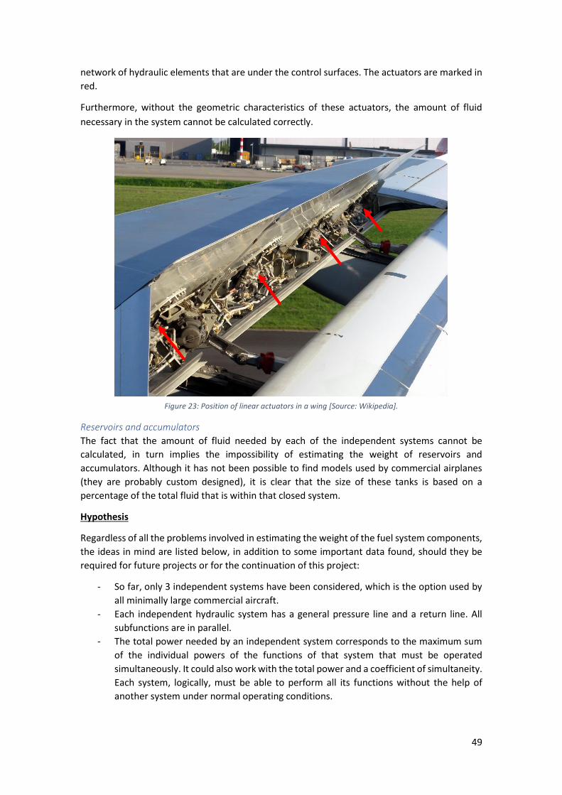
49
network of hydraulic elements that are under the control surfaces. The actuators are marked in
red.
Furthermore, without the geometric characteristics of these actuators, the amount of fluid
necessary in the system cannot be calculated correctly.
Reservoirs and accumulators
The fact that the amount of fluid needed by each of the independent systems cannot be
calculated, in turn implies the impossibility of estimating the weight of reservoirs and
accumulators. Although it has not been possible to find models used by commercial airplanes
(they are probably custom designed), it is clear that the size of these tanks is based on a
percentage of the total fluid that is within that closed system.
Hypothesis
Regardless of all the problems involved in estimating the weight of the fuel system components,
the ideas in mind are listed below, in addition to some important data found, should they be
required for future projects or for the continuation of this project:
- So far, only 3 independent systems have been considered, which is the option used by
all minimally large commercial aircraft.
- Each independent hydraulic system has a general pressure line and a return line. All
subfunctions are in parallel.
- The total power needed by an independent system corresponds to the maximum sum
of the individual powers of the functions of that system that must be operated
simultaneously. It could also work with the total power and a coefficient of simultaneity.
Each system, logically, must be able to perform all its functions without the help of
another system under normal operating conditions.
Figure 23: Position of linear actuators in a wing [Source: Wikipedia].

50
- It is considered that if an aircraft has M independent systems with EDP as the main
pump, the hydraulic system has maximum M-1 PTUs. It is also important to decide
whether these PTUs are reversible or not.
- All the EDPs are always running and they have one fire shutoff valve in case of
emergency. Logically an airplane has never had an EDP as backup.
- The independent systems have the same models of EDPs and ACMPs.
- It has been seen in manuals [31] that on each system, the electric pump flow is about
18% of the EDP flow capacity. It can be used to retract the surfaces but should not be
used to replace the engine driven pumps. The why of this value is totally unknown.
- In a system, we do not have actuators as backups that are not working (when activating
one of the subfunctions) waiting for the loss of one of the operating actuators. It is a
redundancy that is only useful if the actuator fails (since the general line is shared and if
it fails the backup actuator would also be inoperative) and would also add too much
extra weight. Redundancy is already sufficiently covered with independent systems.
Program
Operation/Description
Although the program for the hydraulic system has not been done because it was not possible
to advance further in the project with the time available, and because of all the problems
discussed in the previous section, it did count the distribution of the three hydraulic systems to
the control surfaces.
The program was expected to function in the same way as the fuel system: three files (main
program, inputs and drawing module).
So the program calculates and places each of the control surfaces in their corresponding
position, in addition to calculating their area. Then using as reference the criticality and
redundancy analysis of each subsystem (can be found in Appendix J) it places the necessary
actuators on each surface and links them with the relevant independent systems.
Outputs
The result of the operation explained in the previous subsection can be seen in the following
Figure 24:

51
The three independent systems are represented with the colours blue, green and yellow. As an
example, it shows that each system links two actuators (‘nº act’) for each control surface
included in the group that particular system must supply. It can be observed, also, how each
spoiler is activated only by one system, and how the rudder has the 3 systems connected. The
slats in the leading edge are a good example to know how works the definition of subsurfaces:
the user has to introduce the 4 inputs explained before of the total desired area and then select
the ‘nº surf’, 6 in this case.
Future of the program
There are no limitations of the code for the hydraulic system as such since it is unfinished. Future
lines of research should work to solve the main problems discussed above and then proceed
with the development of a first version of the program.
In addition, here are two ideas that could be studied as alternatives to the conventional
hydraulic system:
1. The first would be to separate all control surfaces into subsurfaces all of the same size.
The idea would be to use the same actuator in all of them, being able to simplify the
design of the mechanism in addition to reducing manufacturing costs (only one type of
actuator is purchased).
2. The second would be to compare the conventional hydraulic system with an electro-
hydraulic system formed only by electrohydraulic actuators since it is believed that this
system is the future for commercial airplanes. For example, the Boeing 787 is the first
aircraft designed with more electrical systems than hydraulic systems.
Figure 24: Hydraulic systems obtained by the program.

52
Results and Analysis
Before drawing conclusions, the last chapter of the project will obviously only focus on the fuel
system of the aircraft, since as we have seen it is the only one that could be completed.
So it is divided into two sections, the first part to validate the correct internal functioning of the
program, and the second that consists in executing the code for various commercial airplanes
and analyzing the results obtained.
Validation of the program To validate the program, the best way considered to do so was to simulate a base plane and
from there vary key parameters to observe how the program adapted to these changes.
Therefore, the objective is to verify that the results obtained are realistic with each change
made.
As a starting point there is a description of the basic layout (adapted from the Airbus A330-200),
an aircraft that is 60 m long, with a fuselage diameter of 5,6 m. It has an aspect ratio of 10 and
a wingspan of 60 m. It has two tanks in each wing, in addition to the ventilation and central tank.
It should be clarified that the ventilation tanks are not counted from here onwards (so in this
case we have 4 + 1). The two engines under wings require a fuel flow of 3 kg/s each. The APU is
in the tail.
Although many tests have been done to validate the code is consistent with itself, here is
a summary of some of the most significant ones, so as not to lengthen the chapter excessively.
The modifications with respect to the base layout have been made in a way that several inputs
were not changed at the same time as they could confuse the reading of the results. All the
parameters that the program needs and that are not explicitly cited are logically maintained
with the same value when passing from one modification to another. In Table 1 it can be found
a summary of the validation.
Modification 1:
The first modification is basically to double the size of the plane. The distance inputs have
therefore been multiplied by 2, in addition to the separation between internal ribs, to maintain
the proportions.
The results show that effectively the volume of fuel is increased by a factor of 8 (3 dimensions)
and the amount of sealant is also doubled (logically the same cord has been considered). The
total length of ducts is also almost double. This very small difference is due only to connections
with EDPs (which are the same length).
Modification 2:
The second modification adds a compensation tank in the tail.
This logically implies an increase in fuel capacity (not very large, some 8000 L, since the trim
tanks are small), in addition to an increase in piping length. It can be seen that this length is
approximately 30 m, half the length of the plane. So the length between the fuel line to the tail
plus the relevant connections are checked (with the valves and the transfer gallery). The amount
of sealant is also now taken into consideration as there is a tank in the tail to seal.

53
Modification 3:
In the third modification, two independent parameters have been changed at the same time, on
the one hand the space for the fuel system has been narrowed by moving the two main spars,
and on the other an auxiliary boost pump has been added.
The results show clearly the plane now has much less fuel capacity. It can also be seen that
although the “available chord” has been reduced by 28% ((30-12) + (70-60)), the fuel capacity
has been reduced by 47%. This is logical and demonstrates how the program follows the
perimeter of the airfoil, where the beginning of the wing is much thicker than at the end.
Advancing the front spar, therefore, we lose much more fuel capacity than setting back the rear
spar to the same extent.
In addition, there are two more electric pumps, one per motor. The length of the ducts has not
been highlighted since, although the value varies slightly, this is due to the adjustment for the
new position that the galleries now occupy, which limits the available space.
Modification 4:
The fourth modification adds 3 more tanks per wing. In other words the same space that used
to house 2 tanks now houses 5. Increasing the number of tanks in reality is to improve the
reliability of the system.
It can be seen how the number of necessary components has increased, both electric pumps
and valves. The length of ducts has also increased a bit because of the necessity to connect all
these new elements.
Modification 5:
The fifth modification gives the system up to 2 transfer galleries, as can be seen working in the
great Airbus A380.
Logically the number of electric pumps and valves increases. With regard to the length of ducts,
it can be seen how it has increased approximately by adding the wingspan of the plane (60 m
approximately) - the gallery does not cover the entire wingspan of the plane, but it has the
sweep angle, in addition to some connections.
Modification 6:
The sixth modification adds two more engines to the plane, one on each wing, plus an
independent feed (that do not share the same line).
This implies 2 extra EDPs (1 per engine) and 4 more electric pumps boost (2 for each new engine),
plus 5 more valves: 1 low pressure valve for each new engine and the valve that previously
allowed feeding between sides was replaced by 4 valves that allow cross-feed between all
engines. The length has increased by having more feed lines.
Although it is not shown in the table, if modification 6 is executed but without an independent
feed supply to each engine, 19 valves are obtained (a difference of 3 mentioned compared to
the above mentioned) and the piping distance is somewhere between the basic layout and
modification 5.

54
Modification 7:
The seventh modification only increases the fuel flow needed by each engine.
As can be seen in the results, the only parameter that has been modified is the weight, whilst
the corresponding results for the layout are exactly the same. This modification of the weight is
nothing more than the increase in the unit weight of the pumps (EDPs and electric) as it now has
to move a greater flow. More power is required.
Table 1: Comparison between the basic layout and its respective modifications.
Variable Basic M1 M2 M3 M4 M5 M6 M7
GEOMETRY L [m] 60 120 60 60 60 60 60 60
Width fus. [m] 5,6 11,2 5,6 5,6 5,6 5,6 5,6 5,6
AR 10 10 10 10 10 10 10 10
Span [m] 60 120 60 60 60 60 60 60
Taper ratio 0,25 0,25 0,25 0,25 0,25 0,25 0,25 0,25
thickness 11 11 11 11 11 11 11 11
Sweep [º] 30,0 30,0 30,0 30,0 30,0 30,0 30,0 30,0
Front spar [%] 12 12 12 30 12 12 12 12
Rear spar [%] 70 70 70 60 70 70 70 70
ENGINES
Nº eng. Wings 2 2 2 2 2 2 4 2
Nº eng. Tail 0 0 0 0 0 0 0 0
FFR [kg/s] 3 3 3 3 3 3 3 5
APU
APU position Tail Tail Tail Tail Tail Tail Tail Tail
APU shared No No No No No No No No
FUEL LAYOUT
Indep. Feeding
- - - - - - Yes -
Nº Tanks 5 5 5 5 11 5 5 5
Center Tank Yes Yes Yes Yes Yes Yes Yes Yes
Trim Tank No No Yes No No No No No
Nº galleries 1 1 1 1 1 2 1 1
Aux. pumps 0 0 0 1 0 0 0 0
DB Ribs [m] 0,7 1,4 0,7 0,7 0,7 0,7 0,7 0,7
OUTPUTS
Fuel vol. [L] 114318 914549 122667 60572 114318 114318 114318 114318
Nº EDP 2 2 2 2 2 2 4 2
Nº Elect. pumps
7 7 8 9 13 11 11 7
Nº Valves 17 17 20 17 23 24 22 17
L piping [m] 154,6 303,2 185,6 149 170,6 216 213,3 154,6
Sealant [L] 72 144 84 48 72 72 72 72
T. weight [kg] 325,3 526,8 373,9 300,6 378,6 401 451 361,9
The layouts that the program has given as output for each modification, in addition to the basic
system, have not been attached here so as not to overload the reader with information.

55
Comparison with commercial airplanes In this second part, once it has been verified that the program works with coherence when
adapting to changes in variables, it remains to be seen how it estimates the layouts and the total
weight of different commercial aircraft.
For this, and although for the testing and improvement of the program even more airplanes
were used, this section of results will include those that have enough information to configure
their internal layout options. The planes that have been chosen are the following:
- Airbus A310-300
- Airbus A320-200
- Airbus A330-200
- Airbus A340-300
- Airbus A380-800
- McDonnell Douglas DC-10-40
- Boeing 727-200 Advanced
- Boeing 737-200
- Boeing 747-400
- Embraer ERJ145
Firstly, the layout of each commercial aircraft was visually compared with the layout obtained
by the program and also in terms of number and position of elements. The objective was that
the number of components used to be similar, although their position could vary, since each
manufacturer uses its own methodology. The reader should be reminded that the layouts of
different aircraft can be found in Appendix K, whilst the layouts obtained by the program are
shown in Appendix L.
Finally, once the program has been run on all the sample airplanes chosen, the numerical
outputs obtained for each of them are attached in the summary Table 2 together with the fuel
system weight estimates made by the formulas explained in the Literature Review chapter, as
well as the fuel capacity values obtained from manufacturers [32] [33].
It is important to comment that the program has been run on all the models using the same
values with regard to the parameters that present uncertainty, such as for example the sealant
cord or the distance between ribs. Although these values are certainly incorrect with respect to
the actual values, the same are used throughout so that this variability does not influence or
affect the lecture of the results. In practice it is assumed these values should not be very
different between one aircraft and another.

56
Table 2: Results of the program for several airplanes and comparison with other methods.
A310-300 A320-200 A330-200 A340-300 A380-800 DC-10-40 B727-200Adv B737-200 B747-400 ERJ145
Fuel capacity (reality) [L]
Total 61090 23858 139090 141500 330540 100691 28729 20103 216389 5146
Fuel results (program) [L]
Wings 38471,8 17287,2 89383,05 89383,05 313377 83097,67 25231,7 12634,2 145553 5079,26
Center tank 15862,3 6574,5 26606,10 26606,10 0 33469,83 8330,15 5420,93 46583 0
Trim tank 6959,6 0 8427,50 8427,50 38760 0 0 0 20566 0
Total 61293,7 23861,7 124416,65 124416,65 352137 116567,5 33561,85 18055,13 212702 5079,26
Layout’s components (program)
Nº of EDP 2 2 2 4 4 3 3 2 4 2
Nº EMDP 12 7 11 13 21 7 9 7 12 7
Nº of valves 18 18 21 28 43 19 15 12 27 8
Length of piping [m] 160,11 85,02 167,74 223,64 440,3 175,17 147,67 75,85 300,95 79,78
Sealant [L] 50,25 29,05 85,17 85,17 167,48 61,85 32,61 26,19 116,16 19,85
Weight breakdown (program) [kg]
Fuel piping 112,08 59,52 117,418 156,54 308,21 122,62 103,37 53,10 210,67 55,85
EDP 46,66 30,07 55,95 69,79 136,10 70,87 44,16 29,57 111,95 20,32
EMDP 61,2 28,11 60,78 55,86 130,86 35,12 35,94 28,01 66,86 24,18
Valves (main) 27,8 27,81 32,45 43,26 66,44 29,35 23,18 18,54 41,715 12,36
Sealant 67,84 39,21 114,97 114,97 226,10 83,49 44,02 35,35 156,81 26,80
Total 315,58 184,72 381,57 440,43 867,71 341,46 250,66 164,57 588,00 139,50
Weight estimation (literature review) [kg]
Torenbeek [11] 673,75 497,91 806,02 881,78 1505,16 706,54 412,31 350,14 1137,64 215,19
NASA [12] 511,14 290,66 821,28 1117,54 1849,43 817,01 402,17 272,54 1456,88 118,57
Raymer [10] 474,01 244,76 780,42 788,58 1785,50 585,74 212,18 170,90 1177,90 61,11
Roskam [34] 1954 518 260,82 1053
Ratio 1,75 1,86 2,10 2,11 1,97 2,06 1,37 1,61 2,14 0,94

57
Analysis of the results obtained shown in the table:
With regard to fuel capacity, it can be confirmed that the program very satisfactorily estimates
the maximum amount available according to the geometry of the aircraft and based on the
assumptions made. Some planes obtain more accurate results than others. It should be noted,
however, that the estimated volumes for the trim tanks in tail are always greater than the real
ones. This clearly indicates that the consideration that they cover 60% of the tail span is too
much, or that the tail spars are even closer to each other. In any case, this is indicative as the
program calculates the maximum volume available with the geometry entered. From that
maximum volume the manufacturer can then decide whether to use everything for fuel or not,
and also whether they have to place additional tanks to increase the range of the aircraft.
Moving on to the number of components, it is clear to see what has already been shown step
by step in the previous subsection. The program clearly adapts to the complexity of the aircraft
introduced. In the case of ERJ145 or B737, small aircraft with low distribution complexity. Next
come the bulk of aircraft examined, with an increase in both the number of valves and electric
pumps. Finally, it is reached the largest aircraft, the A380, where it is verified how its second
gallery significantly increases the number of components used. The simulated B747 distances a
little from the real scheme as it is a strange case where the manufacturer also places transfer
pumps in 2 of the feed tanks.
We reach the final point of the project: the comparison of the estimated weight values of the
fuel system. The weight values obtained from the references found will be discussed first, and
then compared with those obtained by the program. As a reminder, the three formulas for
Torenbeek, NASA and Raymer are, respectively:
𝑊𝑓𝑢𝑒𝑙 𝑠𝑦𝑠𝑡𝑒𝑚 = 36,3 · (𝑁𝑒𝑛𝑔 + 𝑁𝑓𝑡 − 1) + 4,366 · 𝑁𝑓𝑡0,5 · 𝑉𝑓𝑡
0,333 (4)
𝑊𝑓𝑢𝑒𝑙 𝑠𝑦𝑠𝑡𝑒𝑚 = 1,07 · 𝑊𝑓𝑢𝑒𝑙 𝑐𝑎𝑝0,58 · 𝑁𝑒𝑛𝑔
0,43 · 𝑉𝑚𝑎𝑥0,34 (5)
𝑊𝑓𝑢𝑒𝑙 𝑠𝑦𝑠𝑡𝑒𝑚 = 2,405 · 𝑉𝑡
0,606 ·1
2· 𝑁𝑡
0,5 (3)
The estimates of Torenbeek and NASA are more or less even in all models. It can be clearly seen
that, although both use fuel capacity as a parameter, NASA's formula gives values higher than
Torenbeeks in larger aircraft: when the capacity barrier of approximately 120.000 L is exceeded,
this parameter has a big influence on the formula used by NASA.
It is also important to comment that another of the parameters used by NASA is the maximum
speed, in the form of a Mach number. All commercial airplanes have similar values for this
variable (except the ERJ145, which is clearly a much smaller aircraft), which is not considered as
an input of great influence for commercial aircrafts.
Taking into account that the last parameter used by NASA is the number of engines, which at
present can be 2, 3 or 4, it can be said that more or less all the work of NASA statistics is based
on the size of the airplane, or its wingspan, as the basic parameter for determining the weight
of the system. Although the formula may or may not be very precise with respect to the actual
values (not even the correlation coefficient is indicated), the only weights that increase
proportionally with the size are the amount of sealant and the length of ducts. Although in
practice it can be shown that a greater size entails more complexity, this increase in size by itself

58
does not require us to use more components or make the system more redundant if it is not
decided to do so.
With the Torenbeek formula, in addition to the fuel capacity and the number of engines, it uses
the number of tanks, which is a parameter that implies more or less complexity (and more
components) in the fuel system.
Raymer's formula also uses the number of tanks as a parameter, but ignores the number of
mounted engines. Like the previous two, it also uses the maximum capacity.
It is important to comment that the Roskam values will not be taken into account because there
is not sufficient data regarding the fuel system, nor the weight values of the aircraft from the
group tested. It is also considered that the value of 1954 kg for the DC-10-30 model is incorrect
since it is too large for the characteristics of the aircraft. It has a greater weight than the one
given for the B747 (a larger and more complex aircraft) and also distances itself from the
formulas of Torenbeek, NASA and Raymer, whilst the order of magnitude matches in the other
models.
Having discussed the previous formulas, it is time to compare them with the values obtained
using the program. It can clearly be said that this first version of the program greatly
underestimates the weight of the fuel system. This is logical, since all the restrictions mentioned
in the subsection of Code Limitations (not repeated here so as not to lengthen the document)
contribute to not adding weight to the total. It should be mentioned that the sealant represents
one of the main components of great uncertainty within the fuel system. Just as pumps and
valves are considered well estimated, the sealant can reduce or greatly increase the total weight
just by modifying the "cord area" parameter.
The tendency of the program is as follows: the smaller the plane, the less difference there is
between the obtained and objective values (those estimated by the formula, since there are no
real values). In fact, in the case of ERJ145 the program gives a total weight value greater than
the estimates of NASA and Raymer (which clearly demonstrates they do not adapt well to very
small aircraft). As the size of the airplanes increases, there is a greater difference between the
values of the program and the real ones. This can be seen in the last row of the table, "Ratio",
which is the division between the average of the 3 estimates with the value obtained by the
program. This behavior supports the idea that the underestimation of the weight comes from
the lack of some components, which increase, the larger the plane.
One of the benefits of the program should be highlighted: in the case of the Airbus A380 this
ratio, instead of increasing a little (more than the one that the B747 has), breaks the trend and
decreases. It is the only plane with a double transfer gallery. For all three formulas, it is simply a
larger aircraft, whilst the program is capable of increasing the weight according to its greater
complexity (for this reason the ratio does not follow the increasing trend).
However, although the values obtained are far from the supposed objective, the program is
considered to be very robust to the layout changes introduced. If the program weight outputs
are plotted against the estimates of each of the formulas, it can be seen that despite the great
precision error, there is a very high correlation between them, which implies that the program
is adapting correctly to the variation of the systems. Figure 25, 26 and 27 show these
correlations:

59
Figure 25: Torenbeek vs. Program weights.
Figure 26: NASA vs. Program weights.
Figure 27: Raymer vs. Program weights.
y = 0,5178xR² = 0,8834
0
100
200
300
400
500
600
700
800
900
1000
0 200 400 600 800 1000 1200 1400 1600 1800 2000
Pro
gram
wei
ghts
(kg
)
Raymer weights (kg)
y = 0,4494xR² = 0,9223
0
100
200
300
400
500
600
700
800
900
1000
0 200 400 600 800 1000 1200 1400 1600 1800 2000
Pro
gram
wei
ghts
(kg
)
NASA weights (kg)
y = 0,5221xR² = 0,9582
0
100
200
300
400
500
600
700
800
900
1000
0 200 400 600 800 1000 1200 1400 1600
Pro
gram
wei
ghts
(kg
)
Torenbeek weights (kg)

60
In addition, if the same graph is repeated, but this time with the average of the three estimates,
a correlation coefficient R2 of 0,9613 is achieved, as can be seen in Figure 28.
Figure 28: Average (Torenbeek, NASA and Raymer) vs. Program weights.
It was suggested that a good way to bring the value obtained closer to the objective would be
to determine weight coefficients, a function of the outputs that can be obtained, that represent
all the elements from which information cannot be obtained at present. For example, that the
check valves are a function of the number of components and fuel lines; or that the ventilation
system is a function of the size and number of tanks. In this way, it would not be necessary to
model them. However, it is necessary to achieve this to have real values of how the weight
within the fuel system is subdivided for each of the groups (or components), since these
coefficients cannot be estimated reliably.
Finally, to highlight the opinion that although the total weight is clearly underestimated, it is
considered that the current weight of the new fuel systems is less than the values that are given
in design books or formulas such as those previously mentioned. This is so for one reason:
development of materials over the years has allowed a reduction in the weight of almost all
system components. This reduction does not necessarily imply a reduction in aircraft weight,
since these improvements are often used in other systems to increase the electrical system,
which both the space and automobile industries are betting on.
y = 0,4991xR² = 0,9613
0
100
200
300
400
500
600
700
800
900
1000
0 200 400 600 800 1000 1200 1400 1600 1800
Pro
gram
wei
ghts
(kg
)
Average weights (kg)

61
Conclusions
The main objective of this project has been met - to design a parametric program to obtain the
weight of the fuel system of commercial aircraft. As mentioned throughout the document and
based on the results section, two conclusions can be obtained:
Firstly, at this moment in time, it is not a better tool for calculating weight than current formulas,
which are also simpler.
Secondly it offers greater flexibility and adaptability to different types of aircraft and their
internal design.
However, completing the program to eliminate its existing limitations and its implementation
could result in much more precise numerical results that, together with the ability of the
program to give more flexibility to the user, could become an interesting tool for the initial phase
of the fuel system design. The options to customize, and the representation of the configured
layout also provide a useful improvement over the usual formulas.
With regards to the hydraulic system, future lines of work should seek to obtain all this
confidential or unavailable information that prevents the project from progressing now.
The key to perfecting both systems would be to have a large collection of real data of the exact
weights of each subsystem, in addition to the different components used. This would allow a
perfect model of the system as well as a great tool to validate and polish the code.

62
References
[1] Airbus Industries. A330 Fuel System (Flight Crew Operating Manual). Available from:
http://www.smartcockpit.com/docs/A330-Fuel.pdf.
[2] EATON Aerospace Group. AE645 PTFE Reinforced Convoluted Hose. October 2018.
Available from:
https://www.eaton.com/Eaton/ProductsServices/Aerospace/Fuel/PCT_247874.
[3] PPG Industries. PPG Aerospace. Available from: http://www.ppgaerospace.com.
[4] Airbus Industries. A320 Fuel System (Flight Crew Operating Manual). Available from:
http://www.smartcockpit.com/docs/A330-Fuel.pdf.
[5] Airbus Industries. A310 Fuel System (Flight Crew Operating Manual). Available from:
http://www.smartcockpit.com/docs/A310-Fuel.pdf.
[6] J. Roskam. Airplane Design, Part IV: Layout design of landing gear and systems. Lawrence
(Kansas): DARcorporation; 1986.
[7] Federal Aviation Administration. Aviation Maintenance Technician Handbook - Airframe,
Volume 2 (FAA-H-8083-31A). Oklahoma: U.S. Department of Transportation; 2018.
[8] Eastman Chemical Company. SKYDROL. Available from:
https://www.eastman.com/Brands/EAS/Skydrol/Pages/Home.aspx.
[9] Captain Joe. Airbus Hydraulic system. 2017. Available from:
https://www.youtube.com/watch?v=k5wNKAhCtyw.
[10] D. P. Raymer. Aircraft Design: A Conceptual Approach. Sylmar (California): American
Institute of Aeronautics and Astronautics; 1992.
[11] E. Torenbeek. Synthesis of Subsonic Airplane Design. Delft: Delft University Press; 1982. p.
286.
[12] NASA. The Flight Optimization System Weights Estimation Method. June 2017. Available
from: https://ntrs.nasa.gov/archive/nasa/casi.ntrs.nasa.gov/20170005851.pdf.
[13] Airbus Industries. A340 Fuel System (Flight Crew Operating Manual). Available from:
http://www.smartcockpit.com/docs/A340-Fuel.pdf.
[14] Benson. Boeing-727. Available from: https://www.boeing-727.com/index.htm.
[15] Captain Dave. The A380 Fuel System. 7 September 2017. Available from:
https://captaindave.aero/2017/09/07/the-a380-fuel-system/.
[16] EATON Aerospace Group. Fuel. Available from:
https://www.eaton.com/Eaton/ProductsServices/Aerospace/Fuel/index.htm.
[17] NACA. 4 digit airfoil calculation. Available from: http://airfoiltools.com/airfoil/naca4digit.
63
[18] NPTEL. Chapter 6 - Fuselage and tail sizing. 2013. Available from:
https://nptel.ac.in/courses/101106035/035_Chapter%206_L26_(04-10-2013).pdf.
[Accessed 3 April 2019].
[19] C. Brady, The Boeing 737 Technical Guide. 2019.
[20] L. Jenkinson, P. Simpkin, D. Rhodes. Civil Jet Aircraft Design - Data sets. Available from:
https://booksite.elsevier.com/9780340741528/appendices/default.htm.
[21] J. P. FIelding. Introduction to Aircraft Design. 2nd ed. Cambridge: Cambridge University
Press; 2017.
[22] Federal Aviation Administration. Fuel Line Study. August 1994. Available from:
https://apps.dtic.mil/dtic/tr/fulltext/u2/a284918.pdf.
[23] Continental. AEROPAL and AEROPAL LT - Industrial Hoses. Available from:
https://www.contitech.de/getmedia/6d418cc1-b5d7-4834-b050-b3029ff9aa0b/IFS1782-
En-Aviation-Fueling-Hoses-AEROPAL-LT.pdf.
[24] Jamshid A. Samareh, M. D. Sensmeier. A Study of Vehicle Structural Layouts in Post-WWII
Aircraft. 22 April 2004. Available from:
https://ntrs.nasa.gov/archive/nasa/casi.ntrs.nasa.gov/20040058112.pdf.
[25] PPG Aerospace. Aerospace Sealants. 2017. Available from:
http://www.ppgaerospace.com/getmedia/7149f714-73df-45a0-80a1-
c7ef6999598d/PRC_SealantBrochure0077.pdf.aspx.
[26] Federal Aviation Administration. Aviation Maintenance Technician Handbook - Airframe,
Volume 1 (FAA-H-8083-31A). Oklahoma: U.S. Department of Transportation; 2018.
[27] Canadair. Hydraulic Power - Bombardier CRJ 100. 31 January 2003. Available from:
http://www.smartcockpit.com/docs/Bombardier_CRJ_00-Hydraulic_Power.pdf.
[28] Federal Aviation Administration. Pilot's Handbook of Aeronautical Knowledge (FAA-H-
8083-25B). U.S. Department of Transportation; 2016.
[29] J. Roskam, Airplane Design. Part VI: Preliminary calculation of aerodynamic, thrust and
power characteristics. Lawrence (Kansas): DARcorporation, 1987. pp. 463-475.
[30] P. K. C. Rudolph. Mechanical Design of High Lift Systems for High Aspect Ratio Swept
Wings. Seattle (Washington): NASA; 1998.
[31] Airbus Industries. A330 Hydraulic System (Flight Crew Operating Manual). Available from:
http://www.smartcockpit.com/docs/A330-Hydraulic.pdf.
[32] Airbus. Aircraft Characteristics - Airport Operations & tech data. Available from:
https://www.airbus.com/aircraft/support-services/airport-operations-and-technical-
data/aircraft-characteristics.html.
[33] Boeing. Airport Compatibility. Available from:
https://www.boeing.com/commercial/airports.

64
[34] J. Roskam. Airplane Design, Part V: Component weight estimation. Lawrence (Kansas):
DARcorporation; 1985.

65
Appendices
Appendix A. Fuel components

66

67
Appendix B: EDP (fuel system)
y = 0,0423x + 8,0202R² = 0,7276
0
5
10
15
20
25
30
35
40
0 100 200 300 400 500 600 700
Flow rate (L/min) vs. Weight (kg)

68
Appendix C: Electrically driven pumps (fuel system)
y = 0,569x + 3,1968R² = 0,8606
0
2
4
6
8
10
12
0 2 4 6 8 10 12 14 16
FFR (kg/s) vs. Weight (kg)
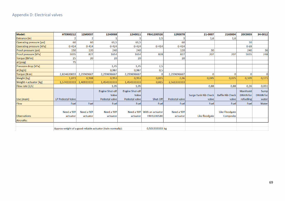
69
Appendix D: Electrical valves

70
Appendix E: Engines families. Thrust and SFC

71
Appendix F: Hoses and fittings

72

73
Appendix G: Inputs of the fuel program
Variable Units Description
PARAMETERS fd kg/L Fuel density
v mm2/s=cSt Fuel kinematic viscosity
u Pa·s = kg/(m·s)
Fuel dynamic viscosity - Optional
sg_s - Specific gravity of the sealant (once cured)
cord_a cm2 Area of the sealant weld
GEOMETRY
L m Length of the aircraft
D_f m Diameter of the fuselage; width
tail_x m Tail position (explained in code)
AR - Aspect ratio
b m Span
tr - Taper ratio
t % Thickness to chord average
sweep º ¼ chord sweep angle
f_spar % Position of the front spar respect to leading edge
r_spar % Position of the rear spar respect to leading edge
n_spars - number of middle spars (extra of the main) - Optional
ribs_dw m Distance between ribs
cranked_wing Yes/No Whether it has cranked wing or trapezoidal wing
AR_ht - Aspect ratio of the horizontal tail
b_ht m Span of the horizontal tail
tr_ht - Taper ratio of the horizontal tail
sweep_ht º ¼ horizontal tail chord sweep
ENGINES
spanwise_loc % Position of the engines in wings
other_eng m Position of the engines in tail
mf kg/s Fuel flow rate per engine
p_mf kPa Pressure at flow rate - Optional
APU
APU_x m Longitudinal distance from wing root chord to APU
APU_shared Yes/No Independent feeding or shared with trim tank
FUEL LAYOUT
in_feed Yes/No If each engine has a feed line or is shared in each wing
Tanks 0/1/v Number and type of tanks under one wing
CT Yes/No Whether it has Center Tank or not
TrimT Yes/No Whether it has Trim Tank or not
ett Unitary Where the tank on tail finishes
n_gal 1/2 Number of transfer galleries
aux_pumps - Number of auxiliary boost pumps
suction_feed Yes/No Whether the feeding pumps have suction valves - Optional
defuel_con 1/2 Whether the feed gallery joins the transfer gallery with 1 or 2 valves
jett Yes/No Whether it has jettison function
jett_loc FF
mid/tip Location of the jettison ejectors
D_p inches Diameter of the fuel pipes

74
Appendix H: Hydraulic system of the A310

75
y = 0,0001x2 + 0,0246x + 1,008R² = 0,9912
0
5
10
15
20
25
0 50 100 150 200 250 300 350
Flow (L/min) vs. Weight (kg)
Appendix I: EDP (Hydraulic system)

76
Appendix J: Hydraulic functions classification

77
Appendix K: Aircraft layouts
Airbus A310
Airbus A320

78
Airbus A340
Airbus A330

79
Boeing 727
Airbus A380

80
Embraer ERJ145
Boeing 737

81
Boeing 747
McDonnell Douglas DC-10-40

82
Appendix L: Layouts estimated by the program
Airbus A310-300
Airbus A320-200

83
Airbus A330-200
Airbus A340-300

84
Airbus A380-800
McDonnell Douglas DC-10-40

85
Boeing 727-200 Advanced
Boeing 737-200

86
Boeing 747-400
Embraer ERJ145