3rdyearnotes.files.wordpress.com€¦ · web viewthe duplexer alternately switches the antenna...
TRANSCRIPT
BANGLADESH
SUBMITTED BY
SHARAT CHANDRA BARMANROLL NO: 0715029
REG. NO: 1075SESSION: 2007-2008
DEPARTMENT OF APPLIED PHYSICS, ELECTRONICS & COMMUNICATION ENGINEERING,
1
1
ISLAMIC UNIVERSITY, KUSHTIA.
PLACE: COX’S BAZAR METEOROGICAL RADAR STATION,BANGLADESH.
2
2
Our major purpose of this field work is to know about –
**How a RADAR is used to detect meteorological condition of a certain region.
3
3
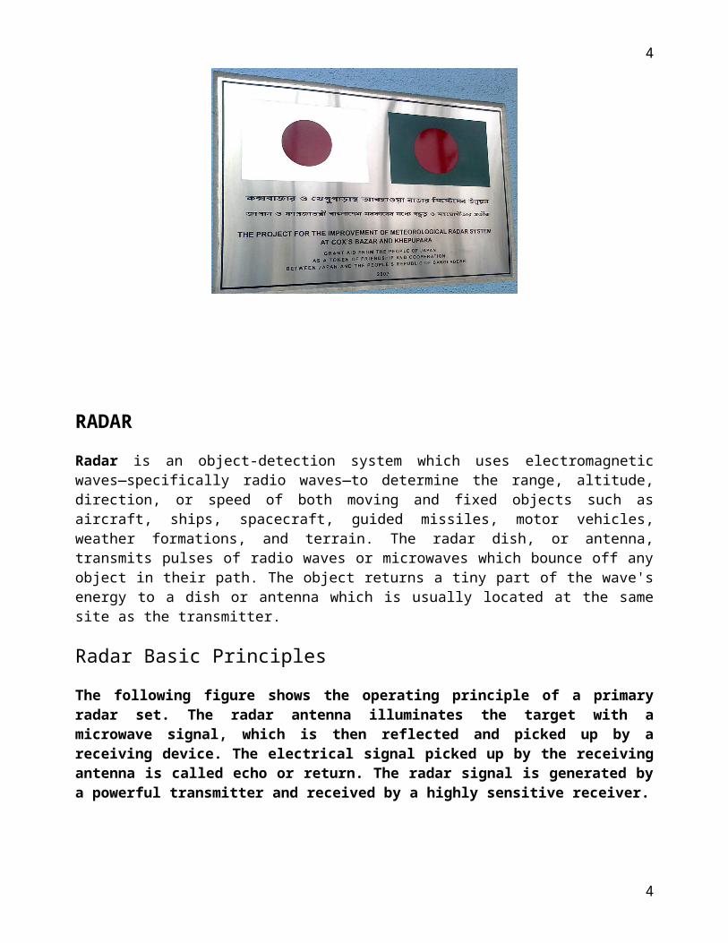
RADAR
Radar is an object-detection system which uses electromagnetic waves—specifically radio waves—to determine the range, altitude, direction, or speed of both moving and fixed objects such as aircraft, ships, spacecraft, guided missiles, motor vehicles, weather formations, and terrain. The radar dish, or antenna, transmits pulses of radio waves or microwaves which bounce off any object in their path. The object returns a tiny part of the wave's energy to a dish or antenna which is usually located at the same site as the transmitter.
Radar Basic Principles
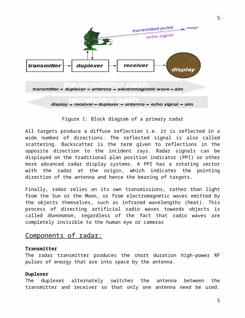
The following figure shows the operating principle of a primary radar set. The radar antenna illuminates the target with a microwave signal, which is then reflected and picked up by a receiving device. The electrical signal picked up by the receiving antenna is called echo or return. The radar signal is generated by a powerful transmitter and received by a highly sensitive receiver.
Figure 1: Block diagram of a primary radar
All targets produce a diffuse reflection i.e. it is reflected in a wide number of directions. The reflected signal is also called scattering. Backscatter is the term given to reflections in the opposite direction to the incident rays. Radar signals can be displayed on the traditional plan position indicator (PPI) or other more advanced radar display systems. A PPI has a rotating vector with the radar at the origin, which indicates the pointing direction of the antenna and hence the bearing of targets.
4
4
Finally, radar relies on its own transmissions, rather than light from the Sun or the Moon, or from electromagnetic waves emitted by the objects themselves, such as infrared wavelengths (heat). This process of directing artificial radio waves towards objects is called illumination, regardless of the fact that radio waves are completely invisible to the human eye or cameras
Components of radar:
Transmitter The radar transmitter produces the short duration high-power RF pulses of energy that are into space by the antenna.
Duplexer The duplexer alternately switches the antenna between the transmitter and receiver so that only one antenna need be used. This switching is necessary because the high-power pulses of the transmitter would destroy the receiver if energy were allowed to enter the receiver.
ReceiverThe receivers amplify and demodulate the received RF-signals. The receiver provides video signals on the output.
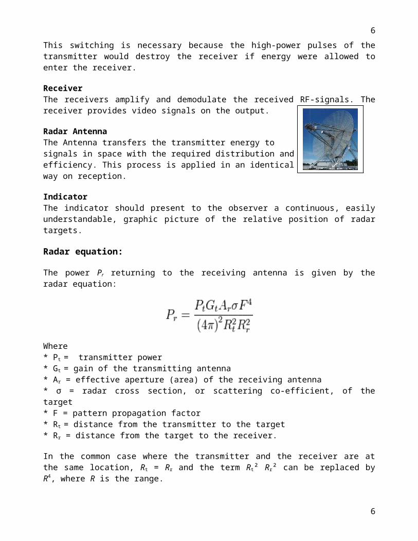
Radar AntennaThe Antenna transfers the transmitter energy to signals in space with the required distribution and efficiency. This process is applied in an identical way on reception.
IndicatorThe indicator should present to the observer a continuous, easily understandable, graphic picture of the relative position of radar targets.
Radar equation:
The power Pr returning to the receiving antenna is given by the radar equation:
Where* Pt = transmitter power* Gt = gain of the transmitting antenna* Ar = effective aperture (area) of the receiving antenna* σ = radar cross section, or scattering co-efficient, of the target* F = pattern propagation factor* Rt = distance from the transmitter to the target * Rr = distance from the target to the receiver.
In the common case where the transmitter and the receiver are at the same location, Rt = Rr and the term Rt² Rr² can be replaced by R4, where R is the range.
5
5
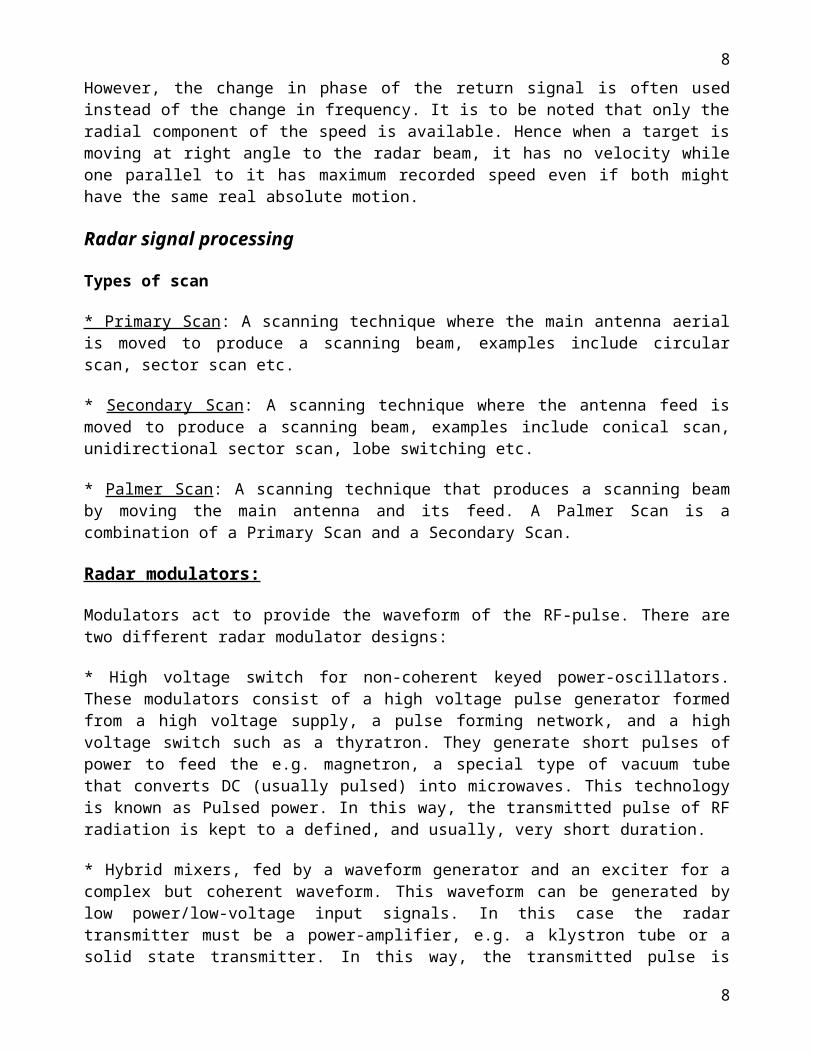
These yields:
This shows that the received power declines as the fourth power of the range, which means that the reflected power from distant targets is very, very small.
The equation above with F = 1 is a simplification for vacuum without interference. The propagation factor accounts for the effects of multipath and shadowing and depends on the details of the environment. In a real-world situation, pathloss effects should also be considered.
Doppler effect
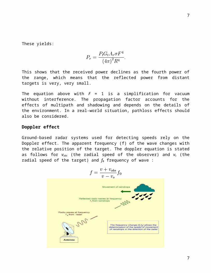
Ground-based radar systems used for detecting speeds rely on the Doppler effect. The apparent frequency (f) of the wave changes with the relative position of the target. The doppler equation is stated as follows for vobs (the radial speed of the observer) and vs (the radial speed of the target) and f0
frequency of wave :
However, the change in phase of the return signal is often used instead of the change in frequency. It is to be noted that only the radial component of the speed is available. Hence when a target is moving at right angle to the radar beam, it has no velocity while one parallel to it has maximum recorded speed even if both might have the same real absolute motion.
6
6
Radar signal processing
Types of scan
* Primary Scan: A scanning technique where the main antenna aerial is moved to produce a scanning beam, examples include circular scan, sector scan etc.
* Secondary Scan: A scanning technique where the antenna feed is moved to produce a scanning beam, examples include conical scan, unidirectional sector scan, lobe switching etc.
* Palmer Scan: A scanning technique that produces a scanning beam by moving the main antenna and its feed. A Palmer Scan is a combination of a Primary Scan and a Secondary Scan.
Radar modulators:
Modulators act to provide the waveform of the RF-pulse. There are two different radar modulator designs:
* High voltage switch for non-coherent keyed power-oscillators. These modulators consist of a high voltage pulse generator formed from a high voltage supply, a pulse forming network, and a high voltage switch such as a thyratron. They generate short pulses of power to feed the e.g. magnetron, a special type of vacuum tube that converts DC (usually pulsed) into microwaves. This technology is known as Pulsed power. In this way, the transmitted pulse of RF radiation is kept to a defined, and usually, very short duration.
* Hybrid mixers, fed by a waveform generator and an exciter for a complex but coherent waveform. This waveform can be generated by low power/low-voltage input signals. In this case the radar transmitter must be a power-amplifier, e.g. a klystron tube or a solid state transmitter. In this way, the transmitted pulse is intrapulsemodulated and the radar receiver must use pulse compression technique mostly.
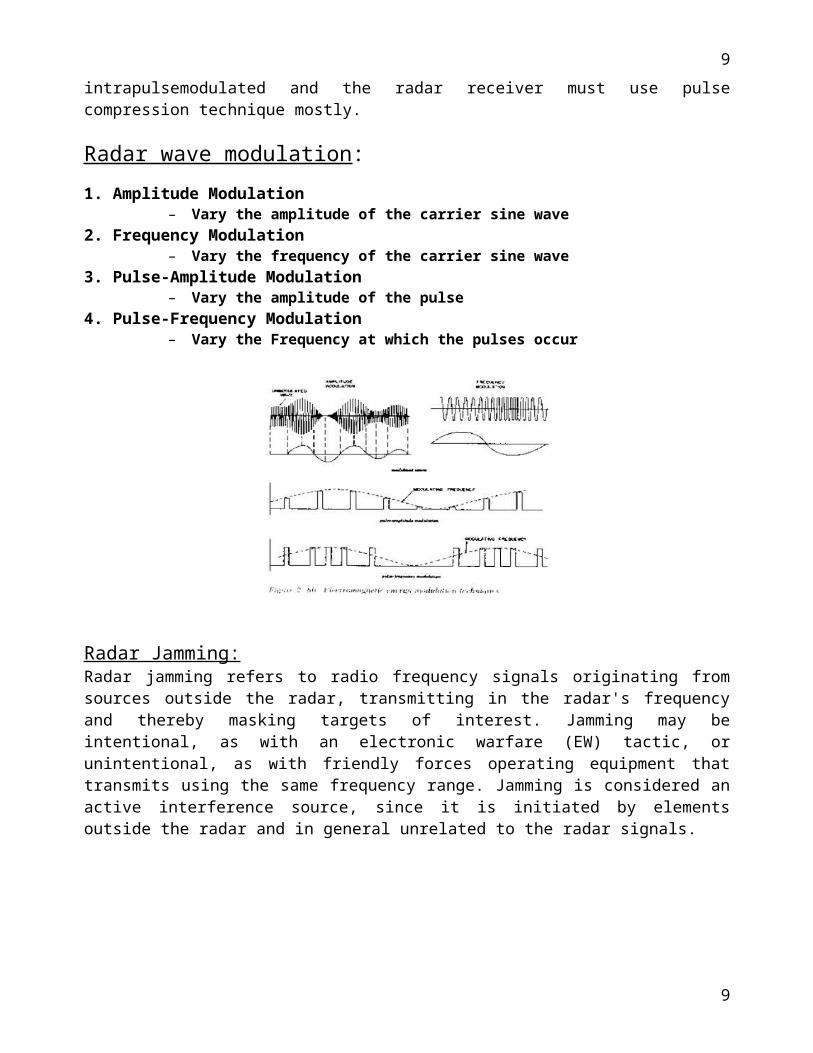
Radar wave modulation:1. Amplitude Modulation
– Vary the amplitude of the carrier sine wave2. Frequency Modulation
– Vary the frequency of the carrier sine wave3. Pulse-Amplitude Modulation
– Vary the amplitude of the pulse4. Pulse-Frequency Modulation
– Vary the Frequency at which the pulses occur
7
7
Radar Jamming:Radar jamming refers to radio frequency signals originating from sources outside the radar, transmitting in the radar's frequency and thereby masking targets of interest. Jamming may be intentional, as with an electronic warfare (EW) tactic, or unintentional, as with friendly forces operating equipment that transmits using the same frequency range. Jamming is considered an active interference source, since it is initiated by elements outside the radar and in general unrelated to the radar signals.
Signal ReceptionSignal Reception
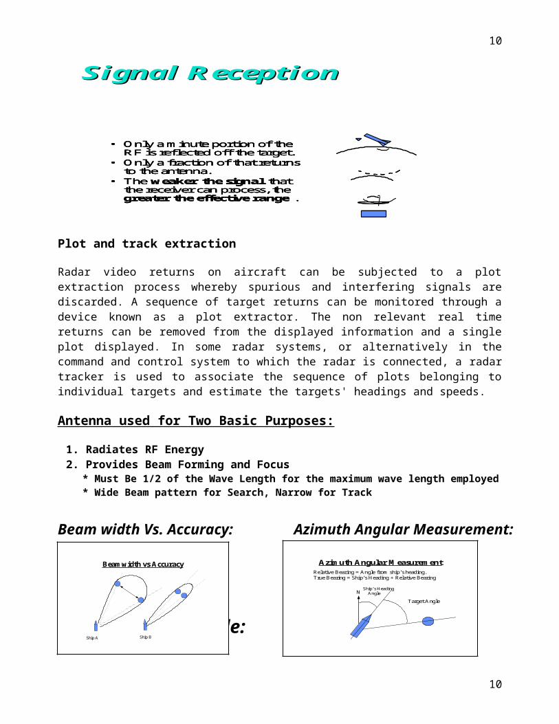
• Only a minute portion of theRF is reflected off the target.
• Only a fraction of that returnsto the antenna.
• The weaker the signal thatthe receiver can process, thegreater the effective range .
• Only a minute portion of theRF is reflected off the target.
• Only a fraction of that returnsto the antenna.
• The weaker the signal thatthe receiver can process, thegreater the effective range .
• Only a minute portion of theRF is reflected off the target.
• Only a fraction of that returnsto the antenna.
• The weaker the signal thatthe receiver can process, thegreater the effective range .
Plot and track extraction
Radar video returns on aircraft can be subjected to a plot extraction process whereby spurious and interfering signals are discarded. A sequence of target returns can be monitored through a device known as a plot extractor. The non relevant real time returns can be removed from the displayed information and a single plot displayed. In some radar systems, or alternatively in the command and control system to which the radar is connected, a radar tracker is used to associate the sequence of plots belonging to individual targets and estimate the targets' headings and speeds.
Antenna used for Two Basic Purposes:
ModulationModulation
8
8
1. Radiates RF Energy2. Provides Beam Forming and Focus
* Must Be 1/2 of the Wave Length for the maximum wave length employed* Wide Beam pattern for Search, Narrow for Track
Beam width Vs. Accuracy: Azimuth Angular Measurement:
Determining Altitude:
Concentrating Radar Energy Through Beam Formation:Linear Arrays:*Uses the Principle of wave summation (constructive interference) in a special direction and wave cancellation (destructive interference) in other directions.*Made up of two or more simple half-wave antennas.Quasi-optical:*Uses reflectors and “lenses” to shape the beam.
Wave Guides:*Used as a medium for high energy shielding.*Uses A Magnetic Field to keep the energy centered in the wave guide.*Filled with an inert gas to prevent arcing due to high voltages within the waveguide.
Two Basic Radar Types:
1. Pulse Transmission.
2. Continuous Wave.
Specific Types of Radar:
1.Frequency Modulated CW Radar *Use for radar altimeters and missile guidance.2.Pulse Doppler *Carrier wave frequency within pulse is compared with a reference signal to detect moving targets. 3.Moving Target Indicator (MTI) System *Signals compared with previous return to enhance moving targets. (search radars)4.Frequency Agile Systems * Difficult to jam
9
9
Beamwidth vs Accuracy
Ship A Ship B
Azimuth Angular MeasurementRelative Bearing = Angle from ship’s heading.True Bearing = Ship’s Heading + Relative Bearing
NShip’s Heading Angle
Target Angle
Waves and Frequency Ranges:
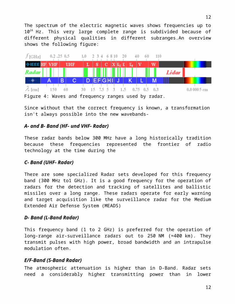
The spectrum of the electric magnetic waves shows frequencies up to 1024 Hz. This very large complete range is subdivided because of different physical qualities in different subranges.An overview shows the following figure:
Figure 4: Waves and frequency ranges used by radar.
Since without that the correct frequency is known, a transformation isn't always possible into the new wavebands-
A- and B- Band (HF- und VHF- Radar)
These radar bands below 300 MHz have a long historically tradition because these frequencies represented the frontier of radio technology at the time during the
C- Band (UHF- Radar)
There are some specialized Radar sets developed for this frequency band (300 MHz to1 GHz). It is a good frequency for the operation of radars for the detection and tracking of satellites and ballistic missiles over a long range. These radars operate for early warning and target acquisition like the surveillance radar for the Medium Extended Air Defense System (MEADS)
D- Band (L-Band Radar)
This frequency band (1 to 2 GHz) is preferred for the operation of long-range air-surveillance radars out to 250 NM (≈400 km). They transmit pulses with high power, broad bandwidth and an intrapulse modulation often.
E/F-Band (S-Band Radar)The atmospheric attenuation is higher than in D-Band. Radar sets need a considerably higher transmitting power than in lower frequency ranges to achieve a good maximum range. As example given the Medium Power Radar (MPR) with a pulse power of up to 20 MW
G- Band (C-Band Radar)In G- Band there are many mobile military battlefield surveillance, missile-control and ground surveillance radar sets with short or medium range.
I/J- Band (X- and Ku- Band Radars)
10
10
In this frequency-band (8 to 12 GHz) the relationship between used wave length and size of the antenna is considerably better than in lower frequency-bands.
K- Band (K- and Ka- Band Radars)The higher the frequency, the higher is the atmospheric absorption and attenuation of the waves. Otherwise the achievable accuracy and the range resolution rise too.
V-Band
By the molecular dispersion (here this is the influence of the air humidity), this frequency band stay for a high attenuation. Radar applications are limited for a short range of a couple of meters here.
W-Band
Here are two phenomena visible: a maximum of attenuation at about 75 GHz and a relative
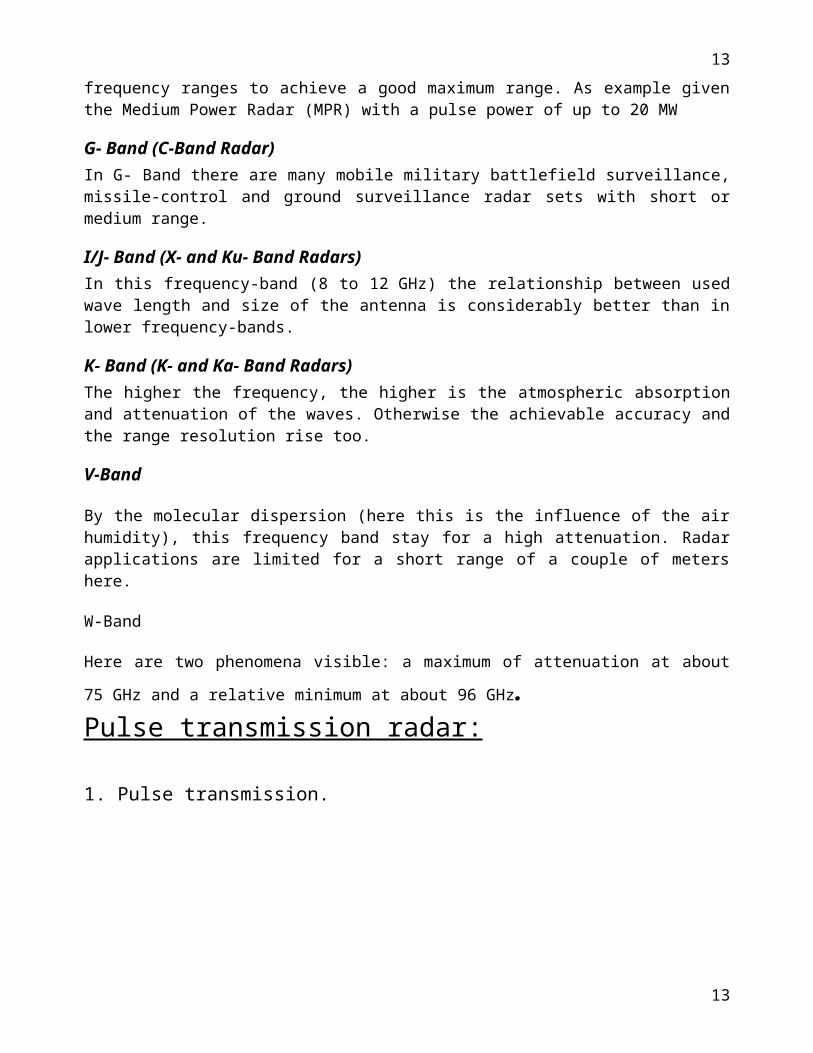
minimum at about 96 GHz.Pulse transmission radar:
1. Pulse transmission.
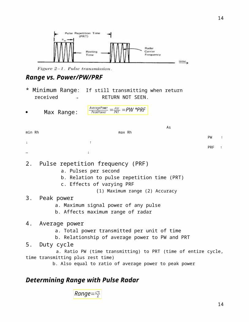
Range vs. Power/PW/PRF
* Minimum Range: If still transmitting when return received → RETURN NOT SEEN.
Max Range:
As min Rh max Rh PW ↑ ↓ ↑ PRF ↑ ↔ ↓
2. Pulse repetition frequency (PRF) a. Pulses per second b. Relation to pulse repetition time (PRT) c. Effects of varying PRF (1) Maximum range (2) Accuracy3. Peak power
11
11
a. Maximum signal power of any pulse b. Affects maximum range of radar
4. Average power a. Total power transmitted per unit of time b. Relationship of average power to PW and PRT5. Duty cycle a. Ratio PW (time transmitting) to PRT (time of entire cycle, time transmitting plus rest time) b. Also equal to ratio of average power to peak power
Determining Range with Pulse Radar
c = 3 x 10⁸ m/sect is time to receive return divided by 2 because pulse traveled to object and back
* Pulse Width (PW) a. Length or duration of a given pulse
* Pulse Repetition Time (PRT=1/PRF) a. PRT is time from beginning of one pulse to the beginning of the next
b. PRF is frequency at which consecutive pulses are transmitted.
* PW can determine the radar’s minimum detection range.
* PRF can determine the radar’s maximum detection range.
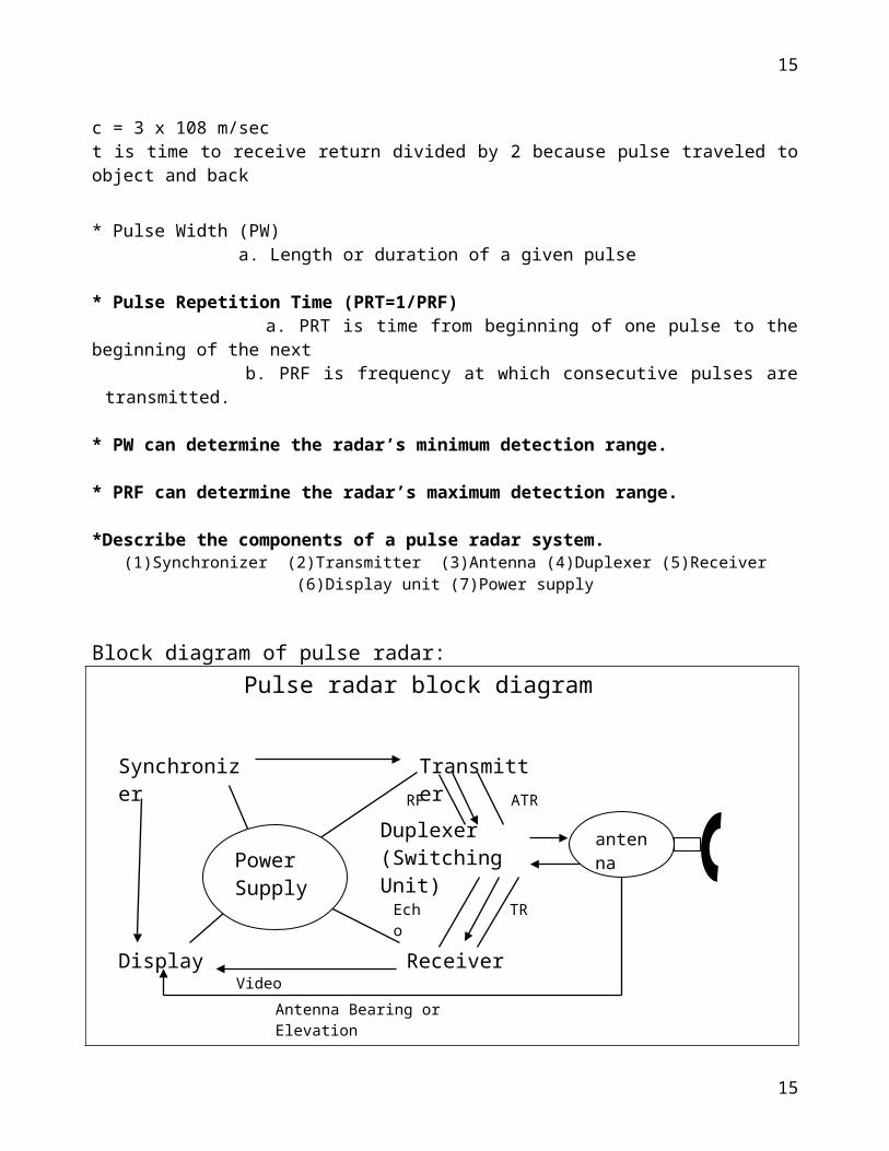
*Describe the components of a pulse radar system.(1)Synchronizer (2)Transmitter (3)Antenna (4)Duplexer (5)Receiver (6)Display unit (7)Power supply
Block diagram of pulse radar:
12
12
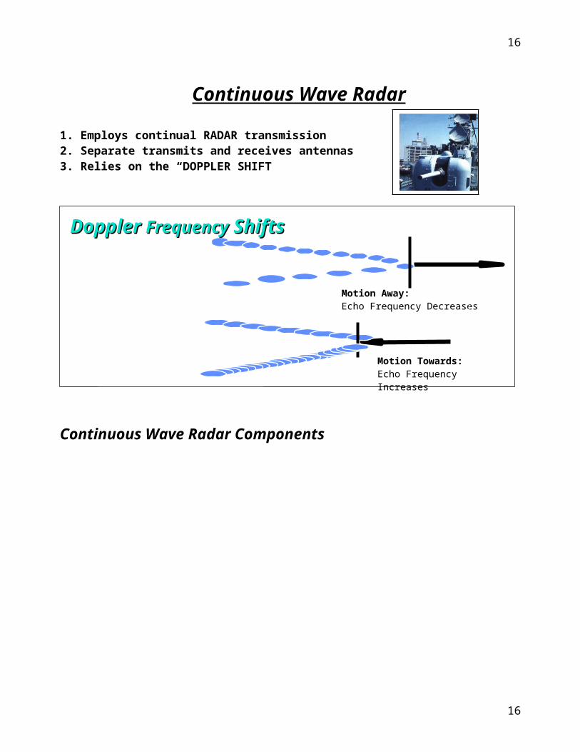
Continuous Wave Radar
1. Employs continual RADAR transmission2. Separate transmits and receives antennas3. Relies on the “DOPPLER SHIFT”
Continuous Wave Radar Components
antenna
Pulse radar block diagram
Synchronizer Transmitter
Display
Duplexer(Switching Unit)
Receiver
Antenna Bearing or Elevation
Video
Echo
ATRRF
TR
PowerSupply
antenna
Motion Away: Echo Frequency Decreases
Motion Towards:Echo Frequency Increases
Doppler Doppler FrequencyFrequency Shifts Shifts
13
13
CW RF
OSCILLITOR
antenna
Pulse Vs Continuous Wave:
Pulse echo Continuous wave1.Single antenna2.Gives range usually Alt. as well.3.susceptibility to jamming.4.physical range determined by PW and PRP .
1.requires 2 antennas.2.range or Alt. Info.3.high SNR.4.More difficult to jam but easily deceived.5.Amp can’t be tuned to look for expected Frequencies.
Applications of Radar
To detect various weather condition. In commercial airliners.
In ground controlled control system.
To determine the fix position, distance and map geographical areas, at seas.
Satellite and other communications
Military operations, etc.
We observed in Cox’s bazaar Meteorological RADAR station Doppler pulse RADAR is used.We observed there are five rooms these are:
1. Electricity Room.2. Data analysis Room.3. Observation Room.4. Storage Room.
14
14
OUT
MIXER
INDICATOR
DIOSCRIMINATORIN
a m p
5. Radar Equipment Room. 6. Maintenance Room.
According to the addressed of RADAR engineer Mr. Md. Abdul Mumin, its basic components are: Magnetron or klystron type oscillator is used to generate microwaves. Rectangular wave guide is used to feed the signal to the antenna to be transmitted. When these signal is reflected by rain bearing cloud (RBC), and received by the antenna these signal is automatically analyzed using Linux Operating system as shown in fig-6. Its range is 440Km and for out of this range satellite is used. These analyzed data are internally sent to Dhaka Met office from where weather related news is telecasted.
Fig-6:Cox's Bazar Radar ImageEnjoying this industrial tour we have come to learn about the system of meteorological radar station and got an idea about the equipments of it. We also learnt about waveguide and its communication techniques. The total system is very complicated & secured. We also realized a concept about the engineer’s role in this organization.
We thank our teachers so much for giving the opportunity to enjoy the sea-beach of Cox’s bazar, Saintmartin-Island beside our study tour. We also thank all my friends especially those who served cordially to present a wonderful tour.
We have made this report from our knowledge & experience throughout this tour and hope that this report will be meaningful and effective. We beg apology for the unavoidable mistake that might happen in this report. Thankfully……………….
3rd year students,Dept. of Applied Physics, Electronics and Communication Engineering.
15
15
Designed by Bhajan Saha & SHARAT
16
16