wcu410 series electroless copper/microetch …...wcu410 series electroless copper/microetch...
TRANSCRIPT
WCU410 Series Electroless Copper/Microetch Controller
Instruction Manual
Five Boynton Road Hopping Brook Park Holliston, MA 01746 USA
TEL: 508-429-1110 FAX: 508-429-7433 WEB: www.walchem.com
W A L C H E M
IWAKI America Inc.
WCU410 Electroless Copper/Microetch Controllers
Notice © 2014 WALCHEM, Iwaki America Inc. (hereinafter “Walchem”) 5 Boynton Road, Holliston, MA 01746 USA (508) 429-1110 All Rights Reserved Printed in USA
Proprietary Material
The information and descriptions contained herein are the property of WALCHEM. Such information and descriptions may not be copied or reproduced by any means, or disseminated or distributed without the express prior written permission of WALCHEM, 5 Boynton Road, Holliston, MA 01746.
This document is for information purposes only and is subject to change without notice.
Statement of Limited Warranty
WALCHEM warrants equipment of its manufacture, and bearing its identification to be free from defects in workmanship and material for a period of 24 months for electronics and 12 months for mechanical parts and electrodes from date of delivery from the factory or authorized distributor under normal use and service and otherwise when such equipment is used in accordance with instructions furnished by WALCHEM and for the purposes disclosed in writing at the time of purchase, if any. WALCHEM’s liability under this warranty shall be limited to replacement or repair, F.O.B. Holliston, MA U.S.A. of any defective equipment or part which, having been returned to WALCHEM, transportation charges prepaid, has been inspected and determined by WALCHEM to be defective. Replaceable elastomeric parts and glass components are expendable and are not covered by any warranty.
THIS WARRANTY IS IN LIEU OF ANY OTHER WARRANTY, EITHER EXPRESS OR IMPLIED, AS TO DESCRIPTION, QUALITY, MERCHANTABILITY, FITNESS FOR ANY PARTICULAR PURPOSE OR USE, OR ANY OTHER MATTER.
180365.G June 2014
TABLE OF CONTENTS
1.0 INTRODUCTION ........................................................................................................................ 1
2.0 SPECIFICATIONS ..................................................................................................................... 2 2.1 Measurement Performance ................................................................................................................... 2 2.2 Electrical: Input/Output .......................................................................................................................... 2 2.3 Mechanical ............................................................................................................................................. 2 2.4 WCU Variables and their Limits ............................................................................................................. 3
3.0 UNPACKING & INSTALLATION ................................................................................................ 4 3.1 Unpacking the unit ................................................................................................................................. 4 3.2 Mounting the electronic enclosure ......................................................................................................... 4 3.3 Immersible Copper Sensor Installation .................................................................................................. 4 3.4 Flow Through Copper Sensor/Sample Loop Installation ....................................................................... 5 3.5 Icon Definitions ...................................................................................................................................... 5 3.6 Electrical installation .............................................................................................................................. 7
4.0 FUNCTION OVERVIEW .......................................................................................................... 10 4.1 Front Panel .......................................................................................................................................... 10 4.2 Display ................................................................................................................................................. 10 4.3 Keypad ................................................................................................................................................. 11 4.4 Access Code ........................................................................................................................................ 11 4.5 Startup ................................................................................................................................................. 11 4.6 Shut Down ........................................................................................................................................... 12
5.0 OPERATION ............................................................................................................................ 12 5.1 Main Menu ........................................................................................................................................... 12 5.2 Sensor Menu ........................................................................................................................................ 14 5.3 Output 1 Menu ..................................................................................................................................... 16 5.4 Output 2 and 3 Menus ........................................................................................................................ 19 5.5 Output 4 and Alarm Menus .................................................................................................................. 21 5.6 4-20 mA 1 and 2 Menus (Optional)...................................................................................................... 25 5.7 Time Menu ........................................................................................................................................... 26 5.8 Access Code Menu .............................................................................................................................. 27 5.9 Datalog Menu ....................................................................................................................................... 28 5.10 Config Menu ......................................................................................................................................... 30 5.11 Upgrade Menu ..................................................................................................................................... 32
6.0 MAINTENANCE ....................................................................................................................... 33 6.1 Sensor Cleaning .................................................................................................................................. 33 6.2 Replacing the Fuses ............................................................................................................................ 33
7.0 TROUBLESHOOTING ............................................................................................................. 34 7.1 Error Messages .................................................................................................................................... 34
8.0 SERVICE POLICY ................................................................................................................... 37
1
1.0 INTRODUCTION The WCU410 series copper controllers are optoelectronic on-line analyzers that may be used in variety of applications including electroless copper baths, microetch baths and a number of other chemistries that contain more than 0.10 grams/liter (g/L) of copper ions. Four control relays are available that may be set up to feed chemicals, or as alarms. A fifth relay is used as a diagnostic alarm. One or two isolated 4-20 mA output that are proportional to the copper concentration are optional. Any set point may be viewed without interrupting control. Each set point change will take effect as soon as it is entered. An access code is available to protect set point parameters, while still allowing settings to be viewed. Either an immersible in-tank sensor or flow-through out-of-tank sensor may be specified. Our unique USB feature provides the ability to upgrade the software in the controller to the latest version. An advanced USB capability option is available. The Configuration file feature allows you to save all the set points from a controller onto a USB flash disk, and then import them into another controller, making the programming of multiple controllers fast and easy. The data logging feature allows you to save the last 2 month’s readings and events to a USB flash disk.

2
2.0 SPECIFICATIONS
2.1 Measurement Performance Electroless Copper Concentration Range 0.1 - 5.5 g/L (0.01 - 0.73 oz/gal) Microetch Copper Concentration Range 0.1 - 99 g/L (0.01 – 13.2 oz/gal)
Copper Concentration Resolution 0.001 g/L (0.0001 oz/gal) Copper Concentration Accuracy ±0.01 g/L (0.001 oz/gal)
Note: The measurement range is the range of settings in the controller. Many factors in the chemical composition affect the absorbance, so Walchem cannot guarantee that every copper solution in this range can be measured.
2.2 Electrical: Input/Output Input Power
100-240 VAC, 50/60 Hz, 8A Fuse: 1.0 ampere, 5 x 20 mm
Input Signals Sensor Signals 0 to 2VDC
Interlock (optional) Isolated, dry contact closure required (i.e., flow, level, etc.) Outputs
Mechanical Relays (5) Internally powered relays switching line voltage 6 A (resistive), 1/8 HP All relays are fused together as one group, total current for this
group must not exceed 6A Note: The Alarm relay is non-programmable as to responding to diagnostic alarms. Refer to the Main Menu diagram for the list of error conditions that trigger the alarm relay.
4 - 20 mA (1 or 2 optional) Internally powered Fully isolated 600 Ohm max resistive load Resolution .001% of span Accuracy ± 1% of reading
Sensor Power + 5VDC, 150 mA
Agency Approvals
Safety UL 61010-1:2012 3rd Ed. CSA C22.2 No. 61010-1:2012 3rd Ed. IEC 61010-1:2010 3rd Ed. EN 61010-1:2010 3rd Ed.
EMC IEC 61326-1:2005 EN 61326-1:2006 Note: For EN61000-4-6, EN61000-4-3 the controller met performance criteria B. *Class A equipment: Equipment suitable for use in establishments other than domestic, and those directly connected to a low voltage (100-240 VAC) power supply network which supplies buildings used for domestic purposes.
2.3 Mechanical
Controller Specifications Enclosure Material Polycarbonate
NEMA Rating NEMA 4X
Dimensions 8.5" x 6.5" x 5.5"
Display 2 x 16 character backlit liquid crystal
Operating Ambient Temp 32 – 122°F (0 – 50°C)
Storage Temperature -20 – 180°F (-29 – 80°C)
3
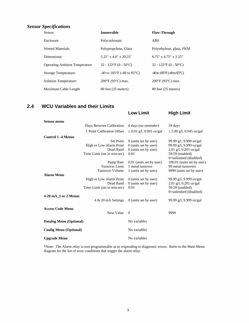
Sensor Specifications Sensor Immersible Flow-Through
Enclosure Polycarbonate ABS
Wetted Materials: Polypropylene, Glass Polyethylene, glass, FKM
Dimensions: 5.25" x 4.0" x 20.25" 6.75" x 4.75" x 2.25"
Operating Ambient Temperature 32 - 122°F (0 - 50°C) 32 - 122°F (0 - 50°C)
Storage Temperature: -40 to 185°F (-40 to 85°C) -40 to 185°F (-40 to 85°C)
Solution Temperature: 200°F (93°C) max. 200°F (93°C) max.
Maximum Cable Length 80 feet (25 meters) 80 feet (25 meters)
2.4 WCU Variables and their Limits Low Limit High Limit
Sensor menu
Days Between Calibration 0 days (no reminder) 59 days
1 Point Calibration Offset ± 0.01 g/l, 0.001 oz/gal ± 5.00 g/l, 0.045 oz/gal
Control 1 -4 Menus Set Point 0 (units set by user) 99.99 g/l, 9.999 oz/gal High or Low Alarm Point 0 (units set by user) 99.99 g/l, 9.999 oz/gal Dead Band 0 (units set by user) 2.01 g/l, 0.201 oz/gal Time Limit (set in min:sec) 0:01 59:59 (enabled)
0=unlimited (disabled) Pump Rate 0.01 (units set by user) 100.01 (units set by user) Turnover Limit 1 metal turnover 99 metal turnovers Turnover Volume 1 (units set by user) 9999 (units set by user) Alarm Menu High or Low Alarm Point 0 (units set by user) 99.99 g/l, 9.999 oz/gal Dead Band 0 (units set by user) 2.01 g/l, 0.201 oz/gal Time Limit (set in min:sec) 0:01 59:59 (enabled)
0=unlimited (disabled) 4-20 mA_1 or 2 Menus 4 & 20 mA Settings 0 (units set by user) 99.99 g/l, 9.999 oz/gal Access Code Menu New Value 0 9999 Datalog Menu (Optional) No variables Config Menu (Optional) No variables Upgrade Menu No variables *Note: The Alarm relay is non-programmable as to responding to diagnostic errors. Refer to the Main Menu diagram for the list of error conditions that trigger the alarm relay.
4
3.0 UNPACKING & INSTALLATION
3.1 Unpacking the unit Inspect the contents of the carton. Please notify the carrier immediately if there are any signs of damage to the controller or its parts. Contact your distributor if any of the parts are missing. The carton should contain: a WCU series controller and instruction manual. Any options or accessories will be incorporated as ordered.
3.2 Mounting the electronic enclosure The WCU series controller is supplied with mounting holes on the enclosure. It should be wall mounted with the display at eye level, on a vibration-free surface, utilizing all four mounting holes for maximum stability. Use M6 (1/4" diameter) fasteners that are appropriate for the substrate material of the wall. The enclosure is NEMA 4X rated. The maximum operating ambient temperature is 122°F (50°C); this should be considered if installation is in a high temperature location. The enclosure requires the following clearances: Top: 2" (50 mm) Left: 8" (203 mm) Right: 4" (102 mm) Bottom: 7" (178 mm)
3.3 Immersible Copper Sensor Installation The immersible copper sensor is designed for direct in-tank monitoring of electroless copper and microetch solutions. By monitoring the copper content directly in the solution, control lag and hydraulic problems are eliminated. The sensor is constructed such that a constant path length exists between the fiber optic light guides. The solution between the light guides absorbs light at specific wavelengths in proportion to the copper concentration. The lamp and electronics are located under the cover of the sensor. In order to avoid a shift in calibration due to condensation, the sensor's cover should NEVER be opened. The immersible sensor is provided with a mounting plate and 20 feet of cable. Extension cable is available if the sensor cannot be mounted within 20 feet of the controller. The maximum cable length is 80 feet. While the positioning of the sensor is not particularly sensitive to the tank layout, the following suggestions are given to aid installation:
Do not place the sensor beside heaters; if solution flow stops, the polypropylene guard may melt.
Do not immerse the entire sensor, or the cable. Place the sensor where the loads of parts will not strike it. Place the sensor in an area of good solution movement, but not directly in the path of any air
agitation. Mount the sensor securely to the rim of the tank using the holes provided. If the tank is rimless,
use a block to provide the support for the mounting plate. Attach the cable's connector to the WCU controller. The connector is keyed, do not force! The
sensor you receive with the controller has already been calibrated.
5
3.4 Flow Through Copper Sensor/Sample Loop Installation The copper flow through sensor is designed for out-of-tank monitoring of electroless copper and microetch solutions. The sensor is designed with a glass tube that contains the copper solution that forms a fixed path length between the lamp and receptor module. The solution absorbs light at specific wavelengths in proportion to the copper concentration. In order to avoid a shift in calibration caused by condensation, the sensor cover should NEVER be removed! The flow through sensor is provided with a mounting plate and 20 feet of cable. Extension cable is available if the sensor cannot be placed within 20 feet of the controller. The maximum cable length is 80 feet. The sample loop consists of a shut off valve, a cooling coil or plate, a sensor and a pump or any combination thereof. The shut off valve is to quickly isolate the system if necessary. A cooling coil or plate is necessary to cool the copper solution down to a temperature acceptable to a sample pump. Cooling the solution is also recommended to help reduce the amount of plate out which may form in the sample loop. The pump may be either a stand alone sample pump (which typically have temperature restriction) or a high temperature pump (which is usually just a branch off the recirculation pump).
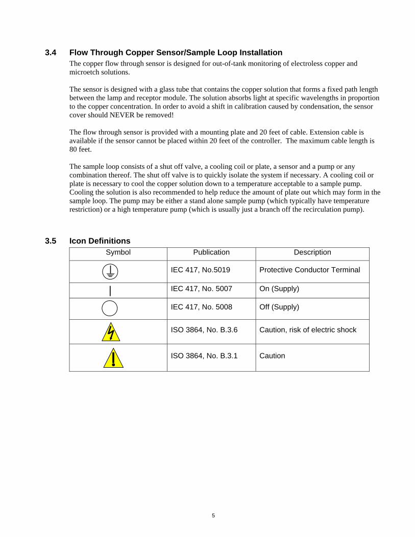
3.5 Icon Definitions Symbol Publication Description
IEC 417, No.5019 Protective Conductor Terminal
IEC 417, No. 5007 On (Supply)
IEC 417, No. 5008 Off (Supply)
ISO 3864, No. B.3.6 Caution, risk of electric shock
ISO 3864, No. B.3.1 Caution
6
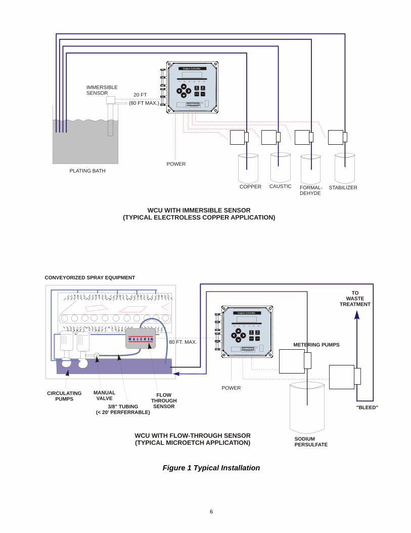
Figure 1 Typical Installation
CONVEYORIZED SPRAY EQUIPMENT
COPPER CAUSTIC FORMAL-DEHYDE
STABILIZER
POWER
POWER
20 FT
IMMERSIBLESENSOR
PLATING BATH
SODIUMPERSULFATE
CIRCULATINGPUMPS
MANUALVALVE
FLOWTHROUGHSENSOR
METERING PUMPS
TOWASTE
TREATMENT
"BLEED"3/8" TUBING(< 20' PERFERRABLE)
WCU WITH FLOW-THROUGH SENSOR(TYPICAL MICROETCH APPLICATION)
WCU WITH IMMERSIBLE SENSOR(TYPICAL ELECTROLESS COPPER APPLICATION)
(80 FT MAX.)
80 FT. MAX.
Copper Controller
www.walchem.com
PREV NEXT
ENTER EXIT
Copper Controller
www.walchem.com
PREV NEXT
ENTER EXIT
7
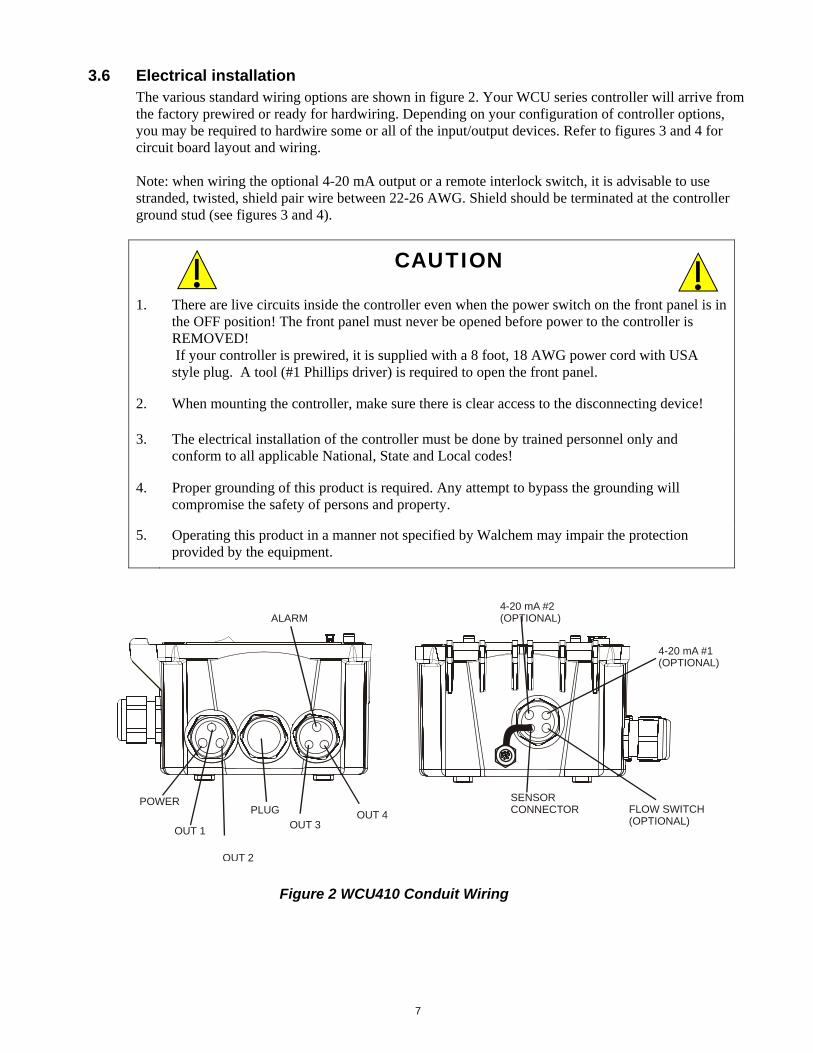
3.6 Electrical installation The various standard wiring options are shown in figure 2. Your WCU series controller will arrive from the factory prewired or ready for hardwiring. Depending on your configuration of controller options, you may be required to hardwire some or all of the input/output devices. Refer to figures 3 and 4 for circuit board layout and wiring. Note: when wiring the optional 4-20 mA output or a remote interlock switch, it is advisable to use stranded, twisted, shield pair wire between 22-26 AWG. Shield should be terminated at the controller ground stud (see figures 3 and 4).
CAUTION
1. There are live circuits inside the controller even when the power switch on the front panel is in the OFF position! The front panel must never be opened before power to the controller is REMOVED! If your controller is prewired, it is supplied with a 8 foot, 18 AWG power cord with USA style plug. A tool (#1 Phillips driver) is required to open the front panel.
2. When mounting the controller, make sure there is clear access to the disconnecting device!
3. The electrical installation of the controller must be done by trained personnel only and conform to all applicable National, State and Local codes!
4. Proper grounding of this product is required. Any attempt to bypass the grounding will compromise the safety of persons and property.
5. Operating this product in a manner not specified by Walchem may impair the protection provided by the equipment.
POWER
OUT 2
OUT 1
FLOW SWITCH(OPTIONAL)
OUT 4OUT 3
4-20 mA #1(OPTIONAL)
PLUGSENSORCONNECTOR
ALARM4-20 mA #2(OPTIONAL)
Figure 2 WCU410 Conduit Wiring
8
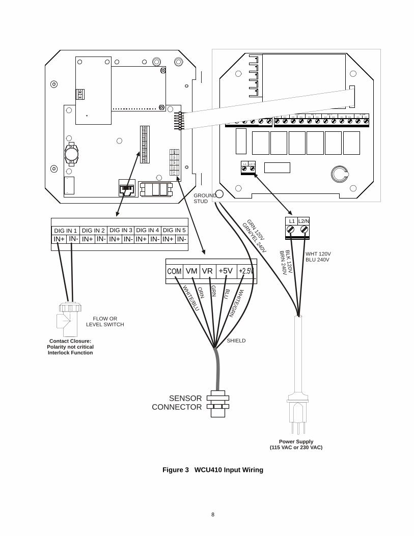
Figure 3 WCU410 Input Wiring
Power Supply(115 VAC or 230 VAC)
Contact Closure:Polarity not criticalInterlock Function
+5V
WH
ITE/B
LU
GROUND STUD
SHIELD
L1 L2/NGR
N 120V
GR
N/YEL 240V
WHT 120VBLU 240V
BLK
120V
BR
N 240V
VM
VR
+5
V
VM VR
OR
N
GR
N
BLU
WH
ITE
/GR
N
IN-DIG IN 2 DIG IN 3
IN+ IN-DIG IN 1
IN+IN-IN+DIG IN 4
IN+ IN-DIG IN 5
IN+ IN-
IN-
DIG
IN 2
DIG
IN 3
IN+
IN-
DIG
IN 1
IN+
IN-
IN+
DIG
IN 4
IN+
IN-
DIG
IN 5
IN+
IN-
L1 L2/N
L2 L2 L2 L2 L2 L2BLEED
N.C. N.O. N.C.
BOI 1
N.O.N.C.
FEED
N.C.
BIO 2
N.O. N.C. N.O. N.O.
ALARM
N.C. N.O.
SENSORCONNECTOR
FLOW OR LEVEL SWITCH
9
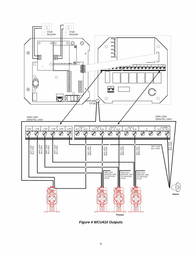
Figure 4 WCU410 Outputs
Pumps
Alarm
L1 L2/N
L2 L2 L2 L2 L2 L2BLEED
N.C. N.O. N.C.
BOI 1
N.O.N.C.
FEED
N.C.
BIO 2
N.O. N.C. N.O. N.O.
ALARM
N.C. N.O.
L2/N L2/N L2/N L2/N L2/N L2/N N.C. N.O.OUT 3
N.O.N.C.OUT 2
N.C.OUT 4
N.O. N.C. N.O.ALARM
N.C. N.O.
GROUNDSTUD
WH
T 1
20V
BLU
240
V
GRN 120VGRN/YEL 240V
GRN 120VGRN/YEL 240V
BLK
120
VB
RN
240
V
VM
ChartRecorder
BLK
120
VB
RN
24
0V
WHT 120VBLU 240V
WH
T 1
20V
BLU
240
V
WH
T 1
20V
BLU
240
V
GRN 120VGRN/YEL 240VTO GROUND STUD
GRN 120VGRN/YEL 240VTO GROUND STUD
GRN 120VGRN/YEL 240VTO GROUND STUD
WH
T 1
20V
BLU
240
V
ChartRecorder
IN-
FL
OW
MT
R 1
FLO
W M
TR
2
IN+
FLO
W S
W 1
IN+
IN-
IN+
FL
OW
SW
2
IN-
IN+
BLK
120
VB
RN
24
0V
BLK
120
VB
RN
24
0V
BLK
120
VB
RN
240
V
VR
10
4.0 FUNCTION OVERVIEW
4.1 Front Panel
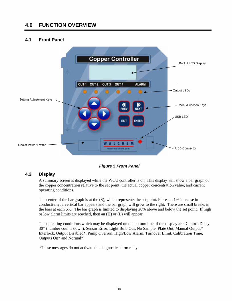
Figure 5 Front Panel
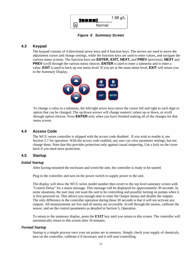
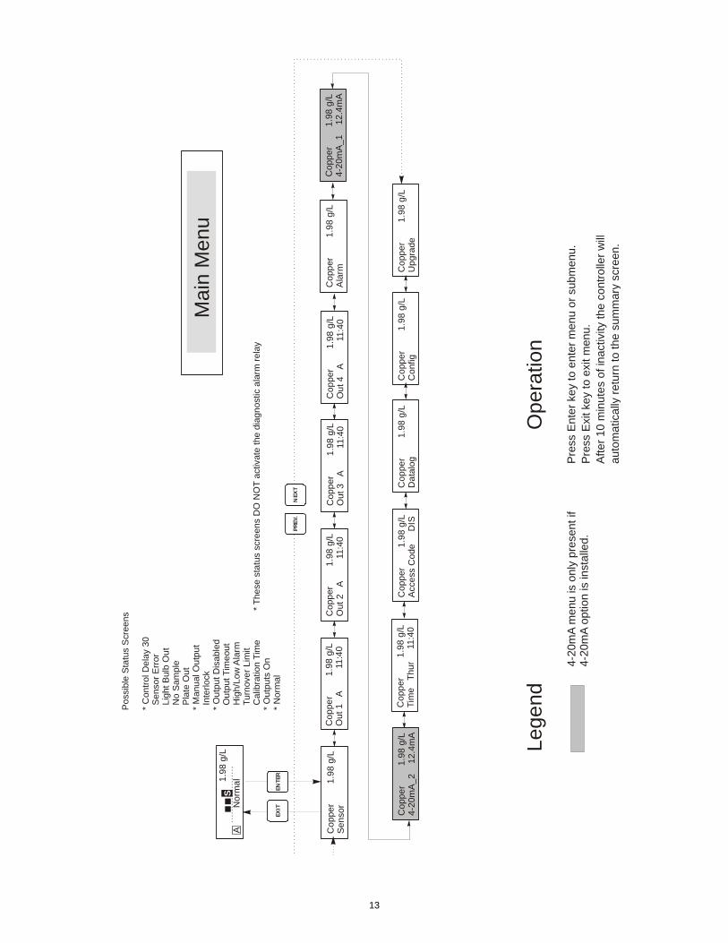
4.2 Display A summary screen is displayed while the WCU controller is on. This display will show a bar graph of the copper concentration relative to the set point, the actual copper concentration value, and current operating conditions. The center of the bar graph is at the (S), which represents the set point. For each 1% increase in conductivity, a vertical bar appears and the bar graph will grow to the right. There are small breaks in the bars at each 5%. The bar graph is limited to displaying 20% above and below the set point. If high or low alarm limits are reached, then an (H) or (L) will appear. The operating conditions which may be displayed on the bottom line of the display are: Control Delay 30* (number counts down), Sensor Error, Light Bulb Out, No Sample, Plate Out, Manual Output* Interlock, Output Disabled*, Pump Overrun, High/Low Alarm, Turnover Limit, Calibration Time, Outputs On* and Normal* *These messages do not activate the diagnostic alarm relay.
On/Off Power Switch
Backlit LCD Display
Output LEDs
Setting Adjustment Keys
Menu/Function Keys
USB Connector
USB LED
11
Figure 6 Summary Screen
4.3 Keypad The keypad consists of 4 directional arrow keys and 4 function keys. The arrows are used to move the adjustment cursor and change settings, while the function keys are used to enter values, and navigate the various menu screens. The function keys are ENTER, EXIT, NEXT, and PREV (previous). NEXT and PREV scroll through the various menu choices. ENTER is used to enter a submenu and to enter a value. EXIT is used to back up one menu level. If you are at the main menu level, EXIT will return you to the Summary Display.
To change a value in a submenu, the left/right arrow keys move the cursor left and right to each digit or option that can be changed. The up/down arrows will change numeric values up or down, or scroll through option choices. Press ENTER only when you have finished making all of the changes for that menu screen.
4.4 Access Code The WCU series controller is shipped with the access code disabled. If you wish to enable it, see Section 5.7 for operation. With the access code enabled, any user can view parameter settings, but not change them. Note that this provides protection only against casual tampering. Use a lock on the cover latch if you need more protection.
4.5 Startup
Initial Startup After having mounted the enclosure and wired the unit, the controller is ready to be started. Plug in the controller and turn on the power switch to supply power to the unit. The display will show the WCU series model number then revert to the top level summary screen with "Control Delay" for a status message. This message will be displayed for approximately 30 seconds. In some situations, the user may not want the unit to be controlling and possibly turning on pumps when it is first powered on. This allows you enough time to enter the Output menus and disable the outputs. The only difference in the controller operation during these 30 seconds is that it will not activate any outputs. All measurements are live and all menus are accessible. Scroll through the menus, calibrate the sensor, and set the control parameters as detailed in Section 5, Operation. To return to the summary display, press the EXIT key until you return to this screen. The controller will automatically return to this screen after 10 minutes.
Normal Startup Startup is a simple process once your set points are in memory. Simply check your supply of chemicals, turn on the controller, calibrate it if necessary and it will start controlling.
12
4.6 Shut Down To shut the WCU controller down, simply turn off the power. Programming remains in memory.
5.0 OPERATION These units control continuously while power is applied. Programming is accomplished via the local keypad and display. To view the top level menu, press any key. The menu structure is grouped by inputs and outputs. Each input has its own menu for calibration and unit selection as needed. Each output has its own setup menu including set points, timer values, etc. as needed. After ten minutes of inactivity in the menu, the display will return to the summary display. Keep in mind that even while browsing through menus, the unit is still controlling.
5.1 Main Menu The exact configuration of your WCU controller determines which menus are available as you scroll through the settings. Certain menus are only available when you select certain options; which may be hardware options (like the installation of a 4-20 mA output board) or software options (like choosing to totalize on volume) or both. All settings are grouped under the following main menu items.
Sensor Output 1 Output 2 Output 3 Output 4 Alarm Time 4-20mA 1 Only if 4-20mA option installed 4-20mA 2 Only if 2nd 4-20mA option installed Access Code Datalog Only if advanced USB feature is in model code Config Only if advanced USB feature is in model code Upgrade
The NEXT key travels forward through this list while the PREV key travels backwards through the list. Pressing ENTER will Enter the lower level menu that is currently displayed.
13
Co
ppe
r
1
.98
g/L
Se
nso
rC
op
per
1.9
8 g
/LO
ut 1
A
11
:40
Cop
per
1.9
8 g
/LO
ut 2
A
1
1:40
Cop
per
1.9
8 g
/LO
ut 3
A
1
1:40
Cop
per
1.9
8 g
/LO
ut
4 A
1
1:4
0
Cop
per
1
.98
g/L
Tim
e T
hur
1
1:4
0
Co
ppe
r
1.98
g/L
4-2
0m
A_
1
12
.4m
A
Co
ppe
r
1.9
8 g/
LA
cce
ss C
ode
DIS
Cop
per
1
.98
g/L
Ala
rm
Mai
n M
enu
Pre
ss E
nter
key
to e
nter
men
u o
r su
bmen
u.P
ress
Exi
t key
to e
xit m
enu.
Afte
r 10
min
utes
of i
nact
ivity
the
cont
rolle
r w
illau
tom
atic
ally
ret
urn
to th
e s
umm
ary
scre
en.
NEX
TP
REV
.
ENTE
REX
IT
Ope
ratio
nLe
gend
4-20
mA
men
u is
onl
y pr
esen
t if
4-20
mA
opt
ion
is in
stal
led.
S1
.98
g/L
No
rma
lA
Po
ssib
le S
tatu
s S
cree
ns
* C
ontr
ol D
ela
y 30
Sen
sor
Err
or
Lig
ht B
ulb
Ou
t N
o S
am
ple
Pla
te O
ut
* M
anu
al O
utp
ut
Int
erlo
ck*
Out
put D
isab
led
Out
put T
imeo
ut H
igh/
Low
Ala
rm T
urn
ove
r L
imit
Cal
ibra
tion
Tim
e*
Out
puts
On
* N
orm
al
* T
hes
e st
atu
s sc
reen
s D
O N
OT
act
ivat
e th
e di
agn
ostic
ala
rm r
elay
Co
ppe
r
1.98
g/L
4-2
0m
A_
2
12.
4m
AC
op
per
1.9
8 g
/LD
ata
log
Co
ppe
r
1.98
g/L
Co
nfig
Co
ppe
r
1
.98
g/L
Up
gra
de

14
Figure 7 Main Menu
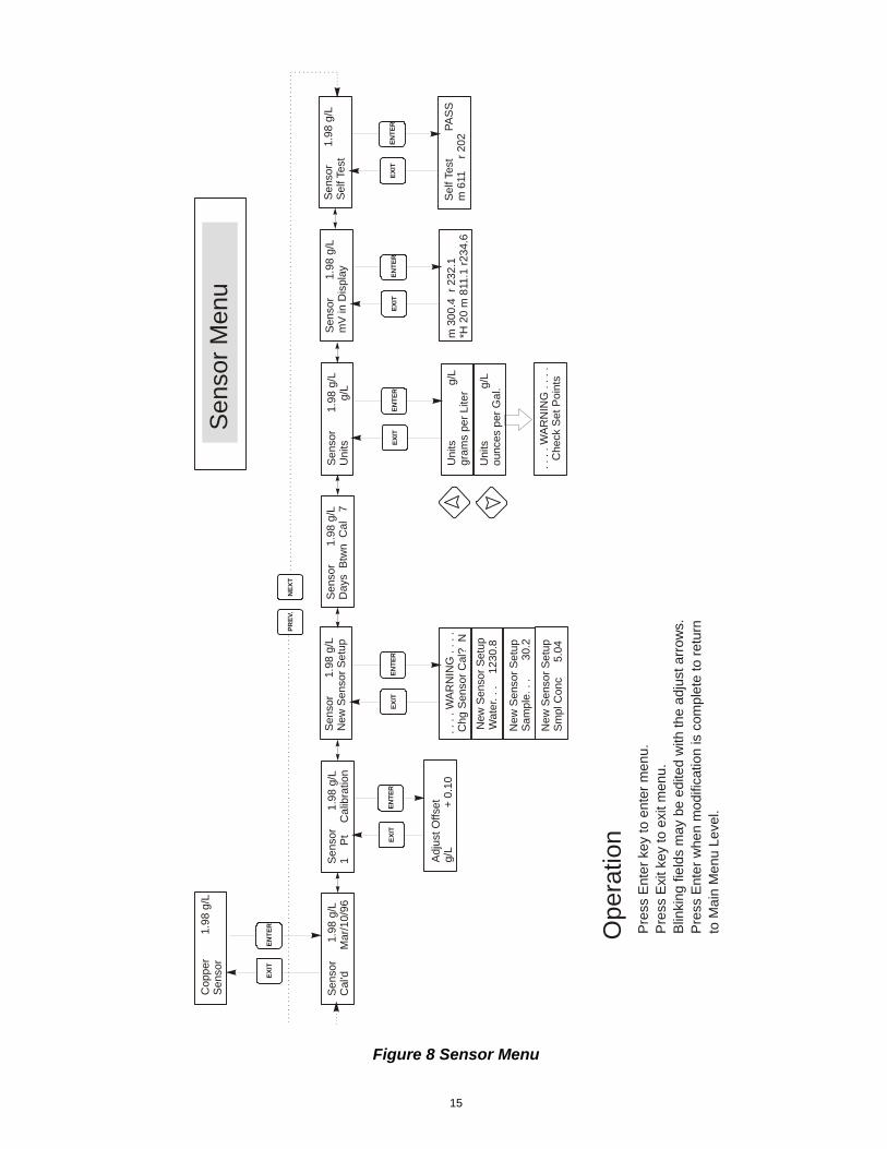
5.2 Sensor Menu The sensor menu provides the following settings: Calibration history (informational only), 2 point calibration, 1 point calibration, sensor type (range) selection, and other calibration menus. Each is discussed in detail below. Refer to the Sensor Menu chart on the next page. Note: If you are programming the unit for the first time, press the PREV key once, and set the "Sensor Type" menu first to choose the range that matches the sensor you have connected. Then press ENTER.
Cal'd Displays the date of the last sensor calibration.
I Pt Calibration Press ENTER to perform a 1 point calibration of the copper sensor. This calibration is best performed at normal operating temperature.
Keep the immersible sensor in place or have solution flowing through the flow-through sensor. Take a sample of the solution and note the concentration displayed by the WCU controller. Carefully perform the normal laboratory analysis of the copper concentration. Calculate the offset by subtracting the displayed value from the lab results. If the lab analysis is significantly different, adjust the offset in the 1 point calibration menu, using the arrow keys to change the value and the +/- sign. If the controller's display is higher than the lab analysis, the offset should be negative.
The maximum offset for a one point calibration is 5 g/l(0.45 oz/gal) from the last new sensor setup value. If you have an offset larger than this, then perform a new sensor setup (see next page).
New Sensor Setup Press ENTER to set up a new sensor. First you see a warning message: "WARNING Chg sensor cal? N" This acts as a safety precaution for those who may only be "browsing" through the menus. If you enter the New Sensor Setup menu, you may easily, inadvertently, change the calibration of the sensor. If you continue with the following procedures, you must recalibrate the new sensor.
Water....xxxx.x
Place the immersible sensor in clean tap or DI water, or circulate through the flow through sensor. When the number on the display is constant, press ENTER.
Sample....xxxx.x
Place the sensor in the bath at a known concentration or restart pumping the bath sample through the flow through sensor. No work should be going through the bath so that the concentration remains constant. Ideally the bath should be at the typical operating copper concentration. When the number on the display is constant, press ENTER.
Smpl Conc
Use the arrow keys to change the displayed number to the actual concentration of the bath in grams/liter or ounces/gallon, depending on the unit of measure you have selected, then press ENTER.
Days Btwn Cal Use the arrow keys to set the number of days that you would like to go by before recalibrating the sensor. The controller will prompt you to recalibrate when that time has expired. Setting the number of days to zero will disable this feature.
mV in Display This menu displays the mV from the sensor. It is useful for troubleshooting. The top line shows 2 live voltage readings from the sensor in millivolts. The bottom line shows the stored values for each sensor signal from the most recent new sensor set up calibration - specifically the signal values measured with water.
Self Test This feature is a diagnostic tool that can help isolate a problem between the sensor and controller. Before initiating the self test, the sensor MUST be disconnected from the controller in order to function properly. When ENTER is pressed the controller disables the sensor inputs and injects 2 test signals, simulating a properly functioning sensor. The controller will display "PASS" or "FAIL" along with a live mV reading. If "PASS" is displayed then it indicates the controller is functioning properly and the problem is likely to be with the sensor. See the troubleshooting section for further details. If "FAIL" is indicated, the controller is defective. Consult your factory representative for service options.
15
Figure 8 Sensor Menu
Se
nso
r
1.
98 g
/LC
al'd
M
ar/
10/9
6S
en
sor
1
.98
g/L
1
Pt
C
alib
ratio
n
Adj
ust
Offs
etg/
L
+
0.1
0
Sen
sor
1
.98
g/L
Day
s B
twn
Cal
7
Cop
per
1
.98
g/L
Sen
sor
Sen
sor
Men
u
Pre
ss E
nter
key
to e
nter
men
u.P
ress
Exi
t ke
y to
exi
t m
enu.
Blin
king fi
eld
s m
ay
be e
dite
d w
ith th
e a
djust
arr
ow
s.P
ress
Ent
er w
hen
mod
ifica
tion
is c
ompl
ete
to r
etur
nto
Main
Menu L
eve
l.
NE
XT
PR
EV
.
EN
TE
RE
XIT
EN
TE
RE
XIT
Ope
ratio
n
Sel
f Tes
t
PA
SS
m 6
11
r 2
02
m 3
00.
4
r 23
2.1
*H 2
0 m
811
.1 r
234
.6
Se
nsor
1.9
8 g/
LS
elf
Test
Sen
sor
1.98
g/L
mV
in D
ispl
ay
EN
TE
RE
XIT
EN
TE
RE
XIT
. . .
. W
AR
NIN
G .
. . .
Chg
Sen
sor
Cal
? N
New
Sen
sor
Se
tup
Wat
er. .
.
123
0.8
Ne
w S
enso
r S
etu
pS
ampl
e. .
.
30
.2
Ne
w S
enso
r S
etu
pS
mpl C
onc
5
.04
Se
nso
r
1.9
8 g
/LN
ew
Sen
sor
Se
tup
EN
TE
RE
XIT
. . .
. WA
RN
ING
. . .
.C
heck
Set
Poi
nts
Sen
sor
1
.98
g/L
Uni
ts
g
/L
Uni
ts
g
/Lgr
ams
per
Lite
r
Uni
ts
g/
Lo
unce
s p
er G
al.
EN
TE
RE
XIT
16
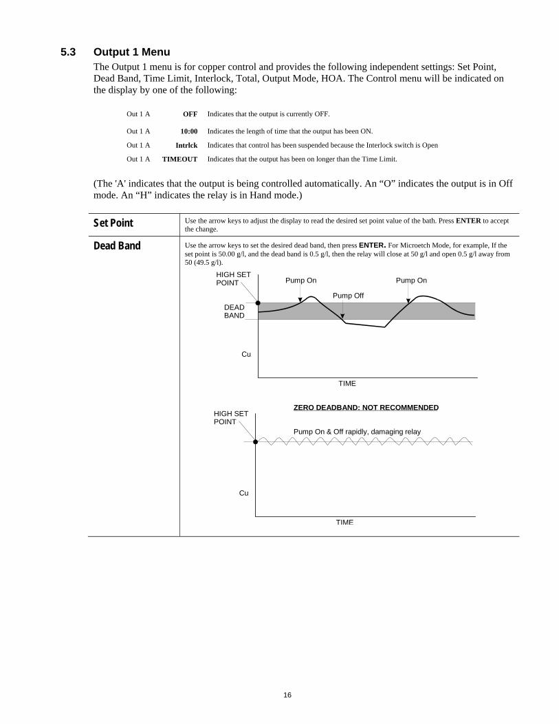
5.3 Output 1 Menu The Output 1 menu is for copper control and provides the following independent settings: Set Point, Dead Band, Time Limit, Interlock, Total, Output Mode, HOA. The Control menu will be indicated on the display by one of the following:
Out 1 A OFF Indicates that the output is currently OFF.
Out 1 A 10:00 Indicates the length of time that the output has been ON.
Out 1 A Intrlck Indicates that control has been suspended because the Interlock switch is Open
Out 1 A TIMEOUT Indicates that the output has been on longer than the Time Limit.
(The 'A' indicates that the output is being controlled automatically. An “O” indicates the output is in Off mode. An “H” indicates the relay is in Hand mode.)
Set Point Use the arrow keys to adjust the display to read the desired set point value of the bath. Press ENTER to accept the change.
Dead Band Use the arrow keys to set the desired dead band, then press ENTER. For Microetch Mode, for example, If the set point is 50.00 g/l, and the dead band is 0.5 g/l, then the relay will close at 50 g/l and open 0.5 g/l away from 50 (49.5 g/l).
DEADBAND
HIGH SETPOINT
Cu
TIME
Pump On
Pump Off
Pump On
HIGH SETPOINT
Cu
TIME
ZERO DEADBAND: NOT RECOMMENDED
Pump On & Off rapidly, damaging relay
17
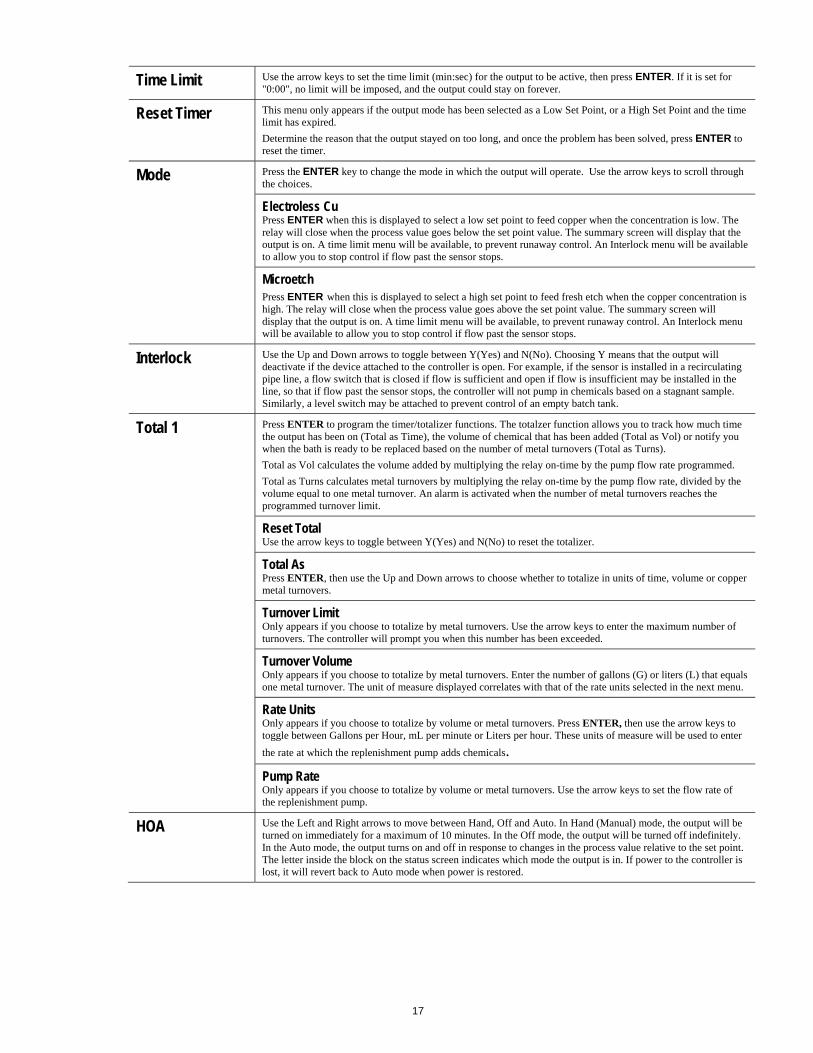
Time Limit Use the arrow keys to set the time limit (min:sec) for the output to be active, then press ENTER. If it is set for "0:00", no limit will be imposed, and the output could stay on forever.
Reset Timer This menu only appears if the output mode has been selected as a Low Set Point, or a High Set Point and the time limit has expired.
Determine the reason that the output stayed on too long, and once the problem has been solved, press ENTER to reset the timer.
Mode Press the ENTER key to change the mode in which the output will operate. Use the arrow keys to scroll through the choices.
Electroless Cu Press ENTER when this is displayed to select a low set point to feed copper when the concentration is low. The relay will close when the process value goes below the set point value. The summary screen will display that the output is on. A time limit menu will be available, to prevent runaway control. An Interlock menu will be available to allow you to stop control if flow past the sensor stops.
Microetch Press ENTER when this is displayed to select a high set point to feed fresh etch when the copper concentration is high. The relay will close when the process value goes above the set point value. The summary screen will display that the output is on. A time limit menu will be available, to prevent runaway control. An Interlock menu will be available to allow you to stop control if flow past the sensor stops.
Interlock Use the Up and Down arrows to toggle between Y(Yes) and N(No). Choosing Y means that the output will deactivate if the device attached to the controller is open. For example, if the sensor is installed in a recirculating pipe line, a flow switch that is closed if flow is sufficient and open if flow is insufficient may be installed in the line, so that if flow past the sensor stops, the controller will not pump in chemicals based on a stagnant sample. Similarly, a level switch may be attached to prevent control of an empty batch tank.
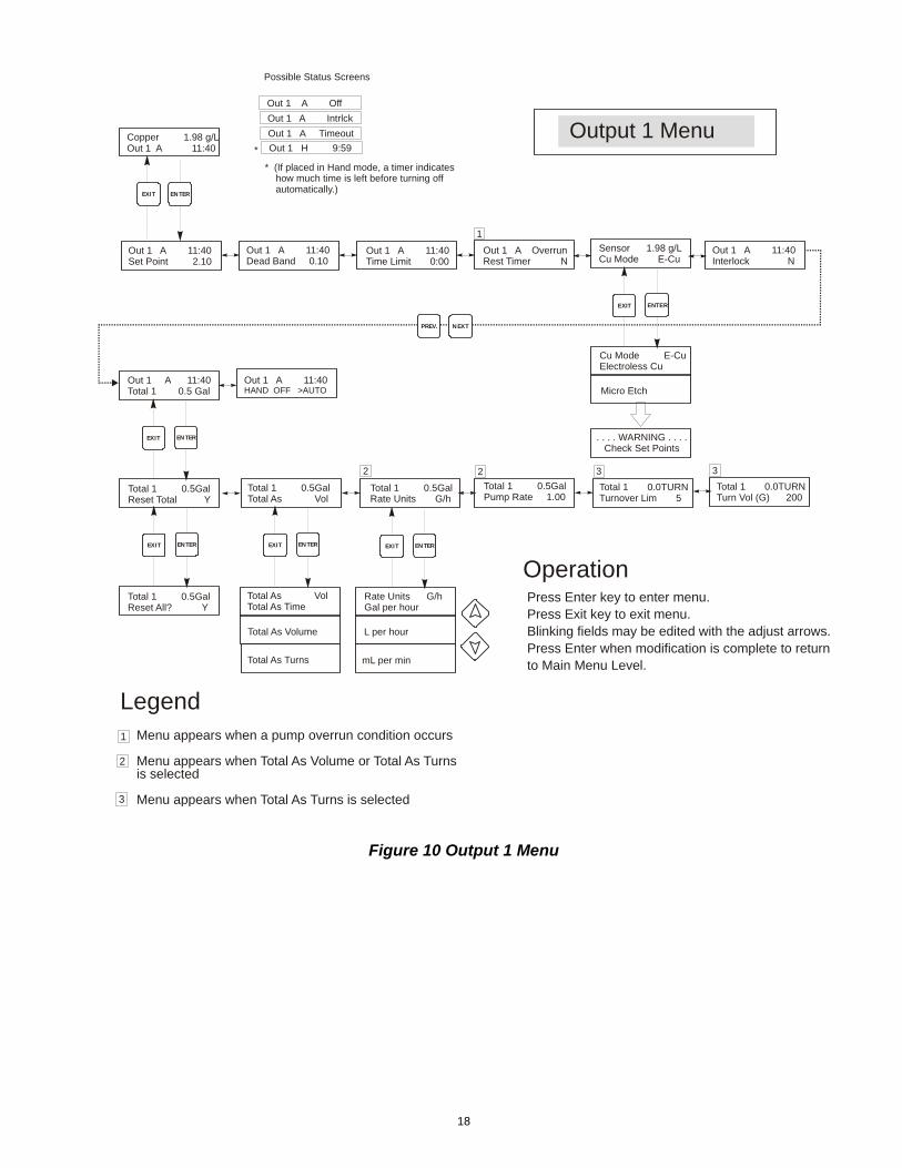
Total 1 Press ENTER to program the timer/totalizer functions. The totalzer function allows you to track how much time the output has been on (Total as Time), the volume of chemical that has been added (Total as Vol) or notify you when the bath is ready to be replaced based on the number of metal turnovers (Total as Turns).
Total as Vol calculates the volume added by multiplying the relay on-time by the pump flow rate programmed.
Total as Turns calculates metal turnovers by multiplying the relay on-time by the pump flow rate, divided by the volume equal to one metal turnover. An alarm is activated when the number of metal turnovers reaches the programmed turnover limit.
Reset Total Use the arrow keys to toggle between Y(Yes) and N(No) to reset the totalizer.
Total As Press ENTER, then use the Up and Down arrows to choose whether to totalize in units of time, volume or copper metal turnovers.
Turnover Limit Only appears if you choose to totalize by metal turnovers. Use the arrow keys to enter the maximum number of turnovers. The controller will prompt you when this number has been exceeded.
Turnover Volume Only appears if you choose to totalize by metal turnovers. Enter the number of gallons (G) or liters (L) that equals one metal turnover. The unit of measure displayed correlates with that of the rate units selected in the next menu.
Rate Units Only appears if you choose to totalize by volume or metal turnovers. Press ENTER, then use the arrow keys to toggle between Gallons per Hour, mL per minute or Liters per hour. These units of measure will be used to enter
the rate at which the replenishment pump adds chemicals.
Pump Rate Only appears if you choose to totalize by volume or metal turnovers. Use the arrow keys to set the flow rate of the replenishment pump.
HOA Use the Left and Right arrows to move between Hand, Off and Auto. In Hand (Manual) mode, the output will be turned on immediately for a maximum of 10 minutes. In the Off mode, the output will be turned off indefinitely. In the Auto mode, the output turns on and off in response to changes in the process value relative to the set point. The letter inside the block on the status screen indicates which mode the output is in. If power to the controller is lost, it will revert back to Auto mode when power is restored.
18
Figure 10 Output 1 Menu
Out 1 A 11:40Set Point 2.10
Out 1 A 11:40Dead Band 0.10
Out 1 A 11:40Time Limit 0:00
Out 1 A OverrunRest Timer N
Copper 1.98 g/LOut 1 A 11:40
Output 1 Menu
Press Enter key to enter menu.Press Exit key to exit menu.Blinking fields may be edited with the adjust arrows.Press Enter when modification is complete to returnto Main Menu Level.
Menu appears when a pump overrun condition occurs
Menu appears when Total As Volume or Total As Turns is selected
Menu appears when Total As Turns is selected
NEXTPREV.
ENTEREXIT
Operation
Legend
Out 1 A Off
Out 1 A Intrlck
Out 1 A Timeout
Out 1 H 9:59
Possible Status Screens
* (If placed in Hand mode, a timer indicates how much time is left before turning off automatically.)
*
Out 1 A 11:40Interlock N
. . . . WARNING . . . .Check Set Points
Sensor 1.98 g/LCu Mode E-Cu
Cu Mode E-CuElectroless Cu
Micro Etch
ENTEREXIT
1
Total 1 0.5GalPump Rate 1.00
Total 1 0.0TURNTurnover Lim 5
Total 1 0.0TURNTurn Vol (G) 200
Out 1 A 11:40Total 1 0.5 Gal
Total 1 0.5GalReset Total Y
Total 1 0.5GalReset All? Y
ENTEREXIT
ENTEREXIT
Out 1 A 11:40HAND OFF >AUTO
L per hour
Total 1 0.5GalTotal As Vol
Total As VolTotal As Time
Total As Volume
Total As Turns
Total 1 0.5GalRate Units G/h
Rate Units G/hGal per hour
mL per min
ENTEREXIT ENTEREXIT
2 3 32
1
2
3
19
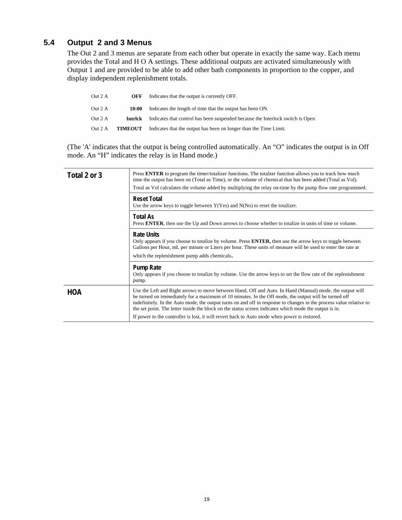
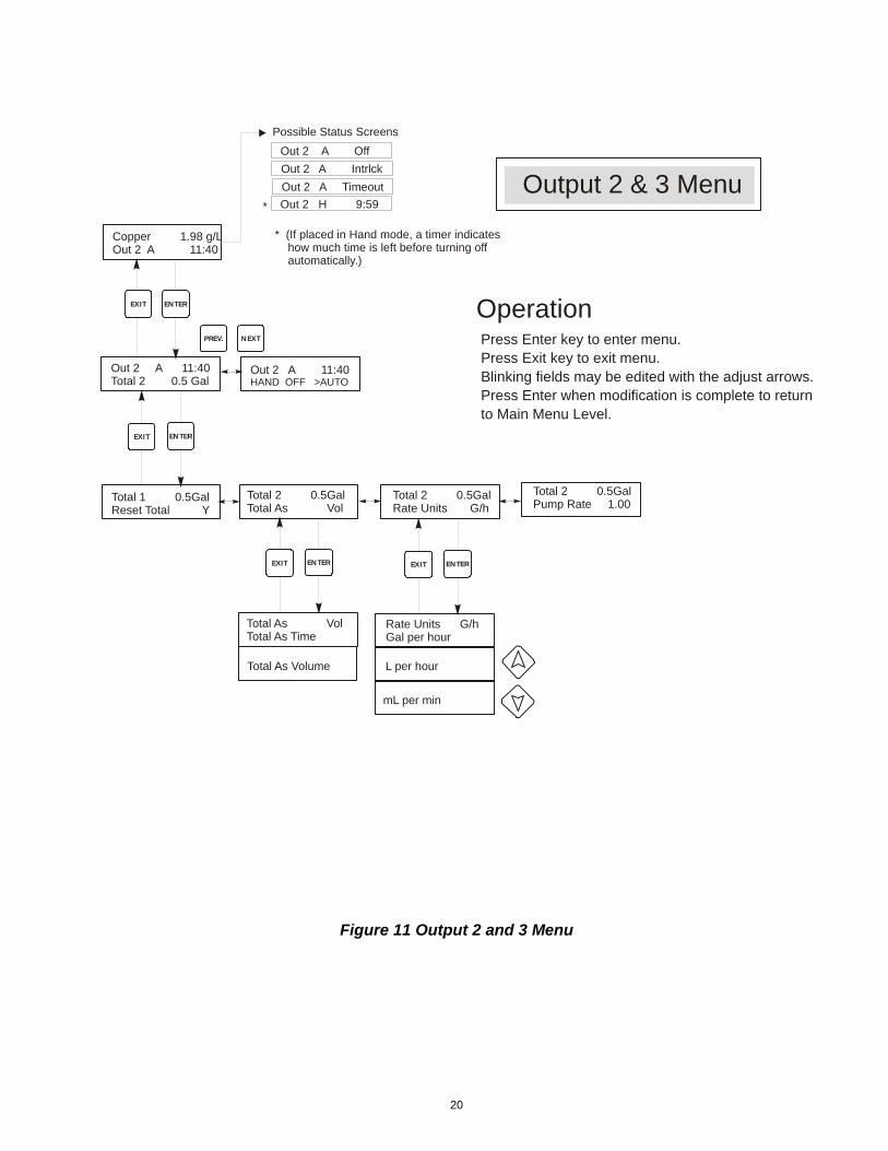
5.4 Output 2 and 3 Menus The Out 2 and 3 menus are separate from each other but operate in exactly the same way. Each menu provides the Total and H O A settings. These additional outputs are activated simultaneously with Output 1 and are provided to be able to add other bath components in proportion to the copper, and display independent replenishment totals.
Out 2 A OFF Indicates that the output is currently OFF.
Out 2 A 10:00 Indicates the length of time that the output has been ON.
Out 2 A Intrlck Indicates that control has been suspended because the Interlock switch is Open
Out 2 A TIMEOUT Indicates that the output has been on longer than the Time Limit.
(The 'A' indicates that the output is being controlled automatically. An “O” indicates the output is in Off mode. An “H” indicates the relay is in Hand mode.)
Total 2 or 3 Press ENTER to program the timer/totalizer functions. The totalzer function allows you to track how much time the output has been on (Total as Time), or the volume of chemical that has been added (Total as Vol).
Total as Vol calculates the volume added by multiplying the relay on-time by the pump flow rate programmed.
Reset Total Use the arrow keys to toggle between Y(Yes) and N(No) to reset the totalizer.
Total As Press ENTER, then use the Up and Down arrows to choose whether to totalize in units of time or volume.
Rate Units Only appears if you choose to totalize by volume. Press ENTER, then use the arrow keys to toggle between Gallons per Hour, mL per minute or Liters per hour. These units of measure will be used to enter the rate at
which the replenishment pump adds chemicals.
Pump Rate Only appears if you choose to totalize by volume. Use the arrow keys to set the flow rate of the replenishment pump.
HOA Use the Left and Right arrows to move between Hand, Off and Auto. In Hand (Manual) mode, the output will be turned on immediately for a maximum of 10 minutes. In the Off mode, the output will be turned off indefinitely. In the Auto mode, the output turns on and off in response to changes in the process value relative to the set point. The letter inside the block on the status screen indicates which mode the output is in.
If power to the controller is lost, it will revert back to Auto mode when power is restored.
20
Figure 11 Output 2 and 3 Menu
Copper 1.98 g/LOut 2 A 11:40
Output 2 & 3 Menu
NEXTPREV.
ENTEREXIT
Out 2 A 11:40Total 2 0.5 Gal
Total 1 0.5GalReset Total Y
ENTEREXIT
Press Enter key to enter menu.Press Exit key to exit menu.Blinking fields may be edited with the adjust arrows.Press Enter when modification is complete to returnto Main Menu Level.
Operation
Out 2 A 11:40HAND OFF >AUTO
Out 2 A Off
Out 2 A Intrlck
Out 2 A Timeout
Out 2 H 9:59
Possible Status Screens
* (If placed in Hand mode, a timer indicates how much time is left before turning off automatically.)
*
Total 2 0.5GalPump Rate 1.00
L per hour
Total 2 0.5GalTotal As Vol
Total As VolTotal As Time
Total As Volume
Total 2 0.5GalRate Units G/h
Rate Units G/hGal per hour
mL per min
ENTEREXIT ENTEREXIT
21
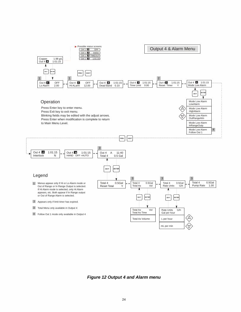
5.5 Output 4 and Alarm Menus Output 4 can be selected to function the same as Outputs 2 and 3, activating at the same time as Output 1, or it may be selected as a programmable alarm relay. The Alarm output (relay 6) will activate in response to any diagnostic alarm plus it can also be selected as a programmable alarm relay. The Output 4 and Alarm menus provide the following independent settings: Set Points, Dead Band, Time Limit, Interlock, Output Mode, and HOA. The Output menu will be indicated on the display by one of the following: NOTE: When programming the unit for the first time, go to the “Mode” menu to select how that output will operate. Making this assignment first will bring up the correct menus for the Mode you are using.
Out 4 A OFF Indicates that the output is currently OFF.
Out 4 A 10:00 Indicates the length of time that the output has been ON.
Out 4 A Intrlck Indicates that control has been suspended because the Interlock switch is Open
Out 4 A TIMEOUT Indicates that the output has been on longer than the Time Limit.
(The 'A' indicates that the output is being controlled automatically. An “O” indicates the output is in Off mode. An “H” indicates the relay is in Hand mode.)
22
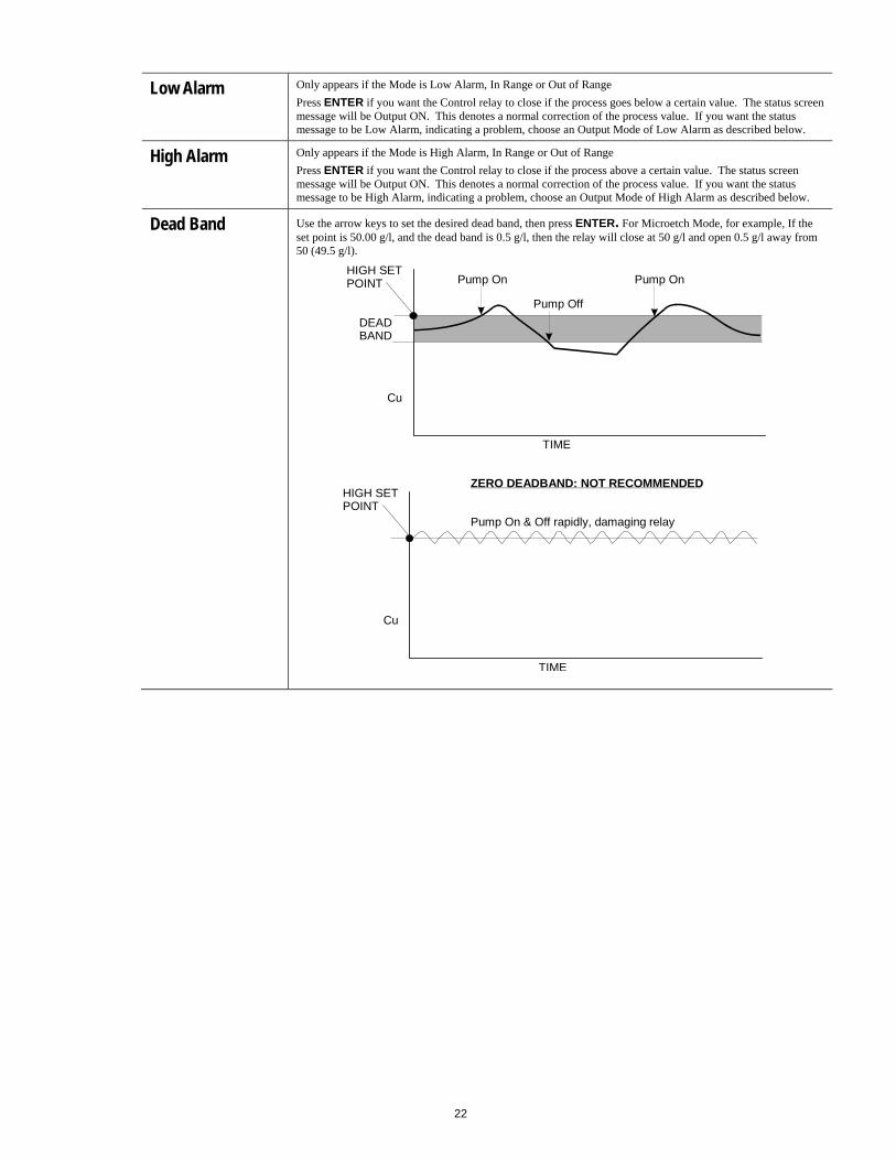
Low Alarm Only appears if the Mode is Low Alarm, In Range or Out of Range
Press ENTER if you want the Control relay to close if the process goes below a certain value. The status screen message will be Output ON. This denotes a normal correction of the process value. If you want the status message to be Low Alarm, indicating a problem, choose an Output Mode of Low Alarm as described below.
High Alarm Only appears if the Mode is High Alarm, In Range or Out of Range
Press ENTER if you want the Control relay to close if the process above a certain value. The status screen message will be Output ON. This denotes a normal correction of the process value. If you want the status message to be High Alarm, indicating a problem, choose an Output Mode of High Alarm as described below.
Dead Band Use the arrow keys to set the desired dead band, then press ENTER. For Microetch Mode, for example, If the set point is 50.00 g/l, and the dead band is 0.5 g/l, then the relay will close at 50 g/l and open 0.5 g/l away from 50 (49.5 g/l).
DEADBAND
HIGH SETPOINT
Cu
TIME
Pump On
Pump Off
Pump On
HIGH SETPOINT
Cu
TIME
ZERO DEADBAND: NOT RECOMMENDED
Pump On & Off rapidly, damaging relay
23
Time Limit This menu only appears if the output mode has been selected as a Low Set Point, or a High Set Point.
Use the arrow keys to set the time limit (min:sec) for the output to be active, then press ENTER. If it is set for "0:00", no limit will be imposed, and the output could stay on forever.
Reset Timer This menu only appears if the output mode has been selected as a Low Set Point, or a High Set Point and the time limit has expired.
Determine the reason that the output stayed on too long, and once the problem has been solved, press ENTER to reset the timer.
Mode Press the ENTER key to change the mode in which the output will operate. The relays may be a low set point, a high set point, a low alarm, a high alarm, an out-of-range alarm, an in-range output, or for Output 4 a Follow Out 1 mode. Use the arrow keys to scroll through the choices.
Low Alarm Press ENTER when this is displayed to select a low alarm. The relay will close when the process value goes below the set point value. The summary screen will display “Low Alarm”. No time limit or interlock features will be available.
High Alarm Press ENTER when this is displayed to select a high alarm. The relay will close when the process value goes above the set point value. The summary screen will display “High Alarm”. No time limit or interlock features will be available.
Out Range Alarm Press ENTER when this is displayed to select an out-of-range alarm. The relay will close when the process value is either above or below the two set point values. The summary screen will display “Range Alarm”. No time limit or interlock features will be available.
In Range Output Press ENTER when this is displayed to select an in-range output. The relay will close when the process value is between the two set point values. The summary screen will display “In Range Output”. No time limit or interlock features will be available.
Follow Out 1 Press ENTER when this is displayed to select Output 4 to activate at the same time as Output 1, to feed a chemical in proportion to the copper.
Interlock Use the Up and Down arrows to toggle between Y(Yes) and N(No). Choosing Y means that the output will deactivate if the device attached to the controller is open. For example, if the sensor is installed in a recirculating pipe line, a flow switch that is closed if flow is sufficient and open if flow is insufficient may be installed in the line, so that if flow past the sensor stops, the controller will not pump in chemicals based on a stagnant sample. Similarly, a level switch may be attached to prevent control of an empty batch tank.
Total 4 Only appears if Output 4 is in Follow Out 1 Mode.
Press ENTER to program the timer/totalizer functions. The totalzer function allows you to track how much time the output has been on (Total as Time), or the volume of chemical that has been added (Total as Vol).
Total as Vol calculates the volume added by multiplying the relay on-time by the pump flow rate programmed.
Reset Total Use the arrow keys to toggle between Y(Yes) and N(No) to reset the totalizer.
Total As Press ENTER, then use the Up and Down arrows to choose whether to totalize in units of time or volume.
Rate Units Only appears if you choose to totalize by volume. Press ENTER, then use the arrow keys to toggle between Gallons per Hour, mL per minute or Liters per hour. These units of measure will be used to enter the rate at
which the replenishment pump adds chemicals.
Pump Rate Only appears if you choose to totalize by volume. Use the arrow keys to set the flow rate of the replenishment pump.
HOA Use the Left and Right arrows to move between Hand, Off and Auto. In Hand (Manual) mode, the output will be turned on immediately for a maximum of 10 minutes. In the Off mode, the output will be turned off indefinitely. In the Auto mode, the output turns on and off in response to changes in the process value relative to the set point. The letter inside the block on the status screen indicates which mode the output is in.
24
Figure 12 Output 4 and Alarm menu
Copper 1.98 g/LOut 4 1:01:15A
Out 4 OFFLo Alarm 2.00
A Out 4 1:01:15Mode Low Alarm
AOut 4 1:01:15Dead Band 0.10
A
Out 4 1:01:15Interlock N
A
Out 4 1:01:15Time Limit 0:00
A
Ctrl 1 OFF
Ctrl 1 Intrlck
Ctrl 1 TIMEOUT
Output 4 & Alarm MenuPossible status screens
Press Enter key to enter menu.Press Exit key to exit menu.Blinking fields may be edited with the adjust arrows.Press Enter when modification is complete to returnto Main Menu Level.
ENTEREXIT
Operation
NEXTPREV.
Out 4 1:01:15Reset Timer Y
A
Out 4 1:01:15HAND OFF >AUTO
A
ENTEREXIT
Mode Low AlarmLowAlarm
Mode Low AlarmHighAlarm
Mode Low AlarmOutRangeAlm
Mode Low AlarmInRangeOutp
Ctrl 1 1:01:15
AAAA
Out 4 OFFHi ALarm 12.00
A
1 1 2
Legend
Menus appear only if Hi or Lo Alarm mode orOut of Range or In Range Output is selected.If Hi Alarm mode is selected, only Hi Alarm appears, etc. Both appear if In Range output or Out of Range Alarm is selected.
Appears only if limit timer has expired.
Total Menu only available in Output 4
Follow Out 1 mode only available in Output 4
1
4
3
2
Out 4 A 11:40Total 4 0.5 Gal
Total 4 0.5GalReset Total Y
ENTEREXIT
Total 4 0.5GalPump Rate 1.00
NEXTPREV.
L per hour
Total 4 0.5GalTotal As Vol
Total As VolTotal As Time
Total As Volume
Total 4 0.5GalRate Units G/h
Rate Units G/hGal per hour
mL per min
ENTEREXIT ENTEREXIT
3
3 3 3
Mode Low AlarmFollow Out 1
4

25
5.6 4-20 mA 1 and 2 Menus (Optional) These menus will only appear if the optional 4-20 mA output board(s) is installed. They are used to set the scale of the 4-20 mA output. It contains the following menu selections: 4 mA Point, 20 mA Point, and Calibrate.
4 mA Pt Use the arrow keys to enter the process value (in the units selected in the Sensor menu) that you want to correspond to a 4 mA output from the controller.
20 mA Pt Use the arrow keys to enter the process value that you want to correspond to a 20 mA output from the controller.
Calibrate This menu is used to calibrate instruments connected to the mA output. The 4-20 mA output is extremely accurate and stable and therefore will never need calibration. This feature allows other devices to be calibrated at the 4 and 20 mA points. Press ENTER to start the calibration.
Fixed 4 mA Out The controller will output 4.00 mA. Adjust the chart recorder or data logger per its instruction so that the process value displayed is what is expected for a 4.00 mA input.
Fixed 20 mA Out As above, except that the controller will output 20.00 mA.
The design of the 4-20 mA output is such that it should never need calibration. If the mA signal is not what it should be, call the factory for service.
Figure 13 4-20 mA 1 and 2 Menus
Copper 1.98g/L4-20mA 12.4mA
4-20mA_1 12.4mASet 4mA Pt 0
4-20mA_1 12.4mACalibrate 4-20mA
4-20mA_1 & 2 Menu
NEXTPREV.
4-20mA menu is only present if4-20mA hardware is installed.
ENTEREXIT
Calibrate 4-20mAFixed 4mA Output
Calibrate 4-20mAFixed 20mA Output
ENTEREXIT
ENTEREXIT
4-20mA_1 12.4mASet 20mA Pt 0
26
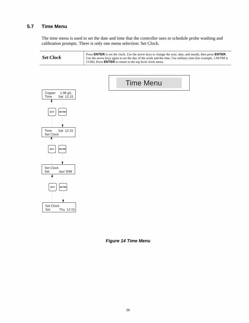
5.7 Time Menu The time menu is used to set the date and time that the controller uses to schedule probe washing and calibration prompts. There is only one menu selection: Set Clock.
Set Clock Press ENTER to set the clock. Use the arrow keys to change the year, date, and month, then press ENTER. Use the arrow keys again to set the day of the week and the time. Use military time (for example, 1:00 PM is 13:00). Press ENTER to return to the top level clock menu.
Figure 14 Time Menu
Copper 1.98 g/LTime Sat 12:15
Time Sat 12:15Set Clock
Set ClockSet Jan/ 3/98
Time Menu
ENTER
ENTER
EXIT
EXIT
Set ClockSet Thu 12:15
ENTEREXIT
27
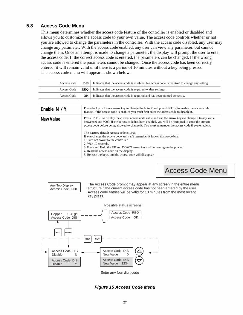
5.8 Access Code Menu This menu determines whether the access code feature of the controller is enabled or disabled and allows you to customize the access code to your own value. The access code controls whether or not you are allowed to change the parameters in the controller. With the access code disabled, any user may change any parameter. With the access code enabled, any user can view any parameter, but cannot change them. Once an attempt is made to change a parameter, the display will prompt the user to enter the access code. If the correct access code is entered, the parameters can be changed. If the wrong access code is entered the parameters cannot be changed. Once the access code has been correctly entered, it will remain valid until there is a period of 10 minutes without a key being pressed. The access code menu will appear as shown below:
Access Code DIS Indicates that the access code is disabled. No access code is required to change any setting.
Access Code REQ Indicates that the access code is required to alter settings.
Access Code OK Indicates that the access code is required and has been entered correctly.
Enable N / Y Press the Up or Down arrow key to change the N to Y and press ENTER to enable the access code feature. If the access code is enabled you must first enter the access code to disable it.
New Value Press ENTER to display the current access code value and use the arrow keys to change it to any value between 0 and 9999. If the access code has been enabled, you will be prompted to enter the current access code before being allowed to change it. You must remember the access code if you enable it. The Factory default Access code is 1995. If you change the access code and can't remember it follow this procedure: 1. Turn off power to the controller. 2. Wait 10 seconds. 3. Press and Hold the UP and DOWN arrow keys while turning on the power. 4. Read the access code on the display. 5. Release the keys, and the access code will disappear.
Figure 15 Access Code Menu
Copper 1.98 g/LAccess Code DIS
Any Top DisplayAccess Code 0000
Access Code DISDisable N
Access Code DISDisable Y
Access Code DISNew Value 0
Access Code DISNew Value 1234
Access Code REQ
Access Code OK
Access Code Menu
Possible status screens
The Access Code prompt may appear at any screen in the entire menustructure if the current access code has not been entered by the user.Access code entries will be valid for 10 minutes from the most recent key press.
Enter any four digit code
ENTEREXIT
NEXTPREV.
28
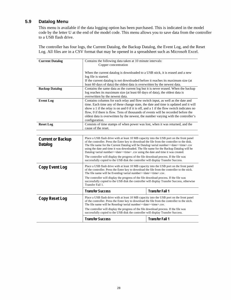
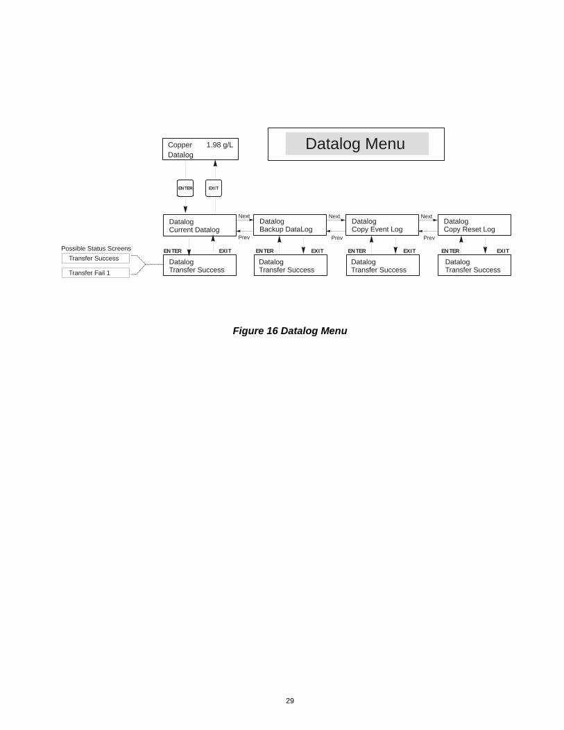
5.9 Datalog Menu This menu is available if the data logging option has been purchased. This is indicated in the model code by the letter U at the end of the model code. This menu allows you to save data from the controller to a USB flash drive. The controller has four logs, the Current Datalog, the Backup Datalog, the Event Log, and the Reset Log. All files are in a CSV format that may be opened in a spreadsheet such as Microsoft Excel. Current Datalog Contains the following data taken at 10 minute intervals:
Copper concentration When the current datalog is downloaded to a USB stick, it is erased and a new log file is started. If the current datalog is not downloaded before it reaches its maximum size (at least 60 days of data) the oldest data is overwritten by the newest data.
Backup Datalog Contains the same data as the current log but it is never erased. When the backup log reaches its maximum size (at least 60 days of data), the oldest data is overwritten by the newest data.
Event Log Contains columns for each relay and flow switch input, as well as the date and time. Each time any of these change state, the date and time is updated and it will show a 1 if the relay is on and 0 if it is off, and a 1 if the flow switch indicates no flow, 0 if there is flow. Tens of thousands of events will be recorded before the oldest data is overwritten by the newest, the number varying with the controller’s configuration.
Reset Log Consists of time stamps of when power was lost, when it was returned, and the cause of the reset.
Current or Backup Datalog
Place a USB flash drive with at least 10 MB capacity into the USB port on the front panel of the controller. Press the Enter key to download the file from the controller to the disk. The file name for the Current Datalog will be Datalog<serial number><date><time>.csv using the date and time it was downloaded. The file name for the Backup Datalog will be Datalog<serial number><date><time> .csv using the date and time it was created.
The controller will display the progress of the file download process. If the file was successfully copied to the USB disk the controller will display Transfer Success.
Copy Event Log Place a USB flash drive with at least 10 MB capacity into the USB port on the front panel of the controller. Press the Enter key to download the file from the controller to the stick. The file name will be Eventlog<serial number><date><time>.csv.
The controller will display the progress of the file download process. If the file was successfully copied to the USB disk the controller will display Transfer Success, otherwise Transfer Fail 1.
Transfer Success Transfer Fail 1
Copy Reset Log
Place a USB flash drive with at least 10 MB capacity into the USB port on the front panel of the controller. Press the Enter key to download the file from the controller to the stick. The file name will be Resetlog<serial number><date><time>.csv.
The controller will display the progress of the file download process. If the file was successfully copied to the USB disk the controller will display Transfer Success.
Transfer Success Transfer Fail 1
29
Figure 16 Datalog Menu
DatalogCurrent Datalog
DatalogCopy Event Log
Datalog Menu
ENTER EXIT
Datalog
DatalogTransfer Success
Next
Prev
DatalogCopy Reset Log
Next
Prev
ENTER EXIT ENTER EXIT ENTER EXIT
DatalogTransfer Success
DatalogTransfer Success
Possible Status Screens
Transfer Success
Transfer Fail 1
DatalogBackup DataLog
Next
Prev
ENTER EXIT
DatalogTransfer Success
Copper 1.98 g/L
30
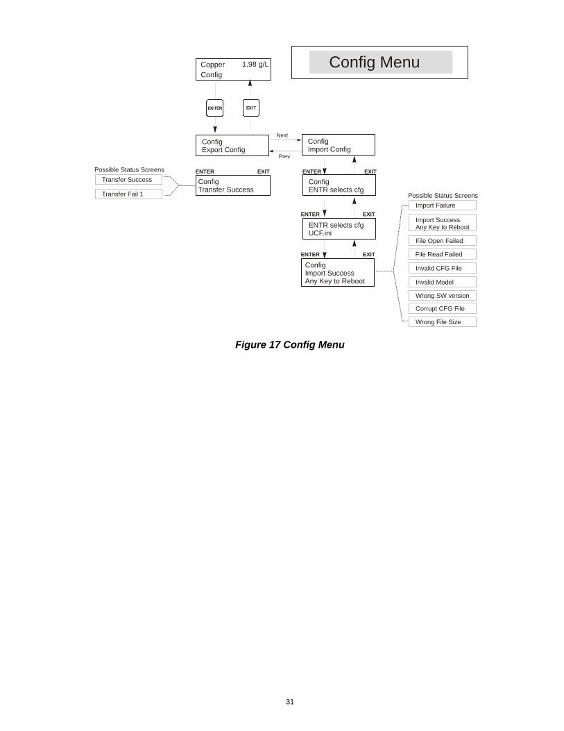
5.10 Config Menu This menu allows you to export a file that contains all of the set points in the controller to a USB flash disk drive, and then later import the set points into another controller.
Export Config Place a USB flash drive with at least 10 MB capacity into the USB port on the front panel of the controller. Press the Enter key to export the configuration file from the controller to the stick. The file name will be UCF.ini. If you are exporting files with different set points you may rename the file to something that describes it, as long as it has an ini extension.
The controller will display the progress of the file download process. If the file was successfully exported to the USB disk the controller will display Transfer Success, otherwise Transfer Fail 1.
Transfer Success Transfer Fail 1
Import Config Place a USB flash drive that contains only one configuration file stored on the root directory of the stick into the USB port on the front panel of the controller. Press the Enter key to import the configuration file from the stick to the controller. The file name must have an ini extension in its name.
The controller will display the progress of the file import process. If the file was successfully imported from the USB disk the controller will display one of the messages below:
Import Failure Indicates that there were problems connecting to or accessing the USB stick.
Import Success: Any key to reboot
The configuration file import succeeded and will be ready for use after reboot.
File Open Failed A config file could not be found on the USB stick or the USB stick file system could not be accessed.
File Read Failed The config file is too short (incomplete) or empty.
Invalid CFG File The imported file is not a valid config file.
Invalid Model The imported config file is not for this controller model.
Wrong SW Version The version of the imported config file is not compatible with this controller software version.
Corrupt CFG File The imported config file is corrupt. (The checksum failed.)
Wrong file Size The size of the imported config file is wrong.
31
Figure 17 Config Menu
ConfigExport Config
ConfigImport Config
Config Menu
ENTER EXIT
1.98 g/L
ConfigCopper
ConfigTransfer Success
ConfigENTR selects cfg
Next
Prev
ConfigImport SuccessAny Key to Reboot
ENTR selects cfgUCF.ini
ENTER EXIT ENTER EXIT
ENTER EXIT
ENTER EXIT
Possible Status Screens
Transfer Success
Transfer Fail 1 Possible Status Screens
Import Failure
Import SuccessAny Key to Reboot
File Open Failed
File Read Failed
Invalid CFG File
Invalid Model
Wrong SW version
Corrupt CFG File
Wrong File Size

32
5.11 Upgrade Menu This menu is used to upgrade the software to a newer version. If a new version of the software is available, an upgrade file will be posted on our web site. Save this file to a USB flash disk drive. It needs to be the only upgrade file stored on the root directory of the stick. Press the Enter key to import the software upgrade file from the stick to the controller. The controller will display the progress of the file import process. If the file was successfully imported from the USB disk the controller will display Transfer Success. The controller will automatically reboot and come up with the new software installed.
Upgrade The controller will display the progress of the file import process. If the file was successfully imported from the USB disk the controller will display Transfer Success. The controller will automatically reboot and come up with the new software installed.
If the software upgrade fails, you will see one of the following messages:
UpgradFileInvald The file found on the USB stick is for the wrong product, or is corrupt. Try getting the correct upgrade file and make sure it’s the only upgrade file on the stick.
No Upgrade File There is no upgrade file stored on the stick, or the file is named incorrectly.
CorrptUpgradFile Try getting a new copy of the file.
Flash Failure The flash memory on the processor board has a problem. Repair or replace the front panel assembly.
To check that it was successful, turn off power to the controller, then press the Enter key while turning power on. The controller will show the software version, which should match the name of the upgrade file that you used.
Figure 18 Upgrade Menu
UpgradeStart Upgrade
Upgrade Menu
ENTER EXIT
1.98 g/L
UpgradeCopper
UpgradeTransfer Success
ENTER EXIT
Possible Status Screens
Transfer Success
UpgradFileInvald
No Upgrade File
CorrptUpgradFile
Flash Failure
33
6.0 MAINTENANCE The WCU control module itself needs very little maintenance. Clean the outside of the controller enclosure with a damp cloth. Do not spray down the controller unless the enclosure door is closed and latched. "Pigtails" should be protected from spray or wash-down. Check the cords and cables for damage.
6.1 Sensor Cleaning NOTE: The controller must be recalibrated after cleaning the sensor.
Frequency The sensor should be cleaned periodically. The frequency required will vary by installation. In a new installation, it is recommended that the sensor be cleaned only if a 1-Point Calibration cannot be successfully performed.
Cleaning Procedure
The most important maintenance item for the sensor is to keep the optical paths clean of plate-out or other coatings. In electroless copper applications, the sensor should be etched when the tank is etched, or whenever plate-out is evident. If plate-out does occur in the sample line or sensor, etch the system as you would the tank. Avoid any mechanical cleaning of the optical surfaces to avoid scratching them. Chemical cleaning is preferred over mechanical cleaning methods. Plate-out should be removed using nitric acid or a persulfate or peroxide/sulfuric etch.
6.2 Replacing the Fuses
CAUTION: Disconnect power to the controller before opening front panel! Locate the fuses on the circuit board at the back of the controller enclosure. (See figure 4.) Gently remove the old fuse from its retaining clip and discard. Press the new fuse into the clip, secure the front panel of the controller and return power to the unit. Warning: Use of non-approved fuses can affect product safety approvals. Fuse ratings depend on controller power rating. Specifications are shown below. To insure product safety certifications are maintained, it is recommended that a Walchem fuse be used. F1 Fuse Walchem P/N F2 Fuse Walchem P/N 5 x 20 mm, 1.0A, 250V 103163 5 x 20 mm, 6A, 250V 102834
34
7.0 TROUBLESHOOTING
CAUTION: Disconnect power to the controller before opening front panel!
Troubleshooting and repair of a malfunctioning controller should only be attempted by qualified personnel using caution to ensure safety and limit unnecessary further damage. Contact the factory.
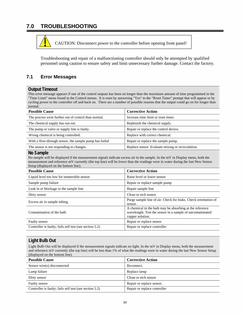
7.1 Error Messages Output Timeout This error message appears if one of the control outputs has been on longer than the maximum amount of time programmed in the "Time Limit" menu found in the Control menus. It is reset by answering "Yes" to the "Reset Timer" prompt that will appear or by cycling power to the controller off and back on. There are a number of possible reasons that the output could go on for longer than normal:
Possible Cause Corrective Action
The process went further out of control than normal. Increase time limit or reset timer.
The chemical supply has run out. Replenish the chemical supply.
The pump or valve or supply line is faulty. Repair or replace the control device.
Wrong chemical is being controlled. Replace with correct chemical.
With a flow-through sensor, the sample pump has failed Repair or replace the sample pump.
The sensor is not responding to changes. Replace sensor. Evaluate mixing or recirculation.
No Sample No sample will be displayed if the measurement signals indicate excess air in the sample. In the mV in Display menu, both the measurement and reference mV currently (the top line) will be lower than the readings were in water during the last New Sensor Setup (displayed on the bottom line).
Possible Cause Corrective Action
Liquid level too low for immersible sensor Raise level or lower sensor
Sample pump failure Repair or replace sample pump
Leak in or blockage or the sample line Repair sample line
Dirty sensor Clean or etch sensor
Excess air in sample tubing Purge sample line of air. Check for leaks. Check orientation of sensor.
Contamination of the bath A chemical in the bath may be absorbing at the reference wavelength. Test the sensor in a sample of uncontaminated copper solution.
Faulty sensor Repair or replace sensor
Controller is faulty; fails self test (see section 5.2) Repair or replace controller
Light Bulb Out Light Bulb Out will be displayed if the measurement signals indicate no light. In the mV in Display menu, both the measurement and reference mV currently (the top line) will be less than 1% of what the readings were in water during the last New Sensor Setup (displayed on the bottom line).
Possible Cause Corrective Action
Sensor wire(s) disconnected Reconnect.
Lamp failure Replace lamp
Dirty sensor Clean or etch sensor
Faulty sensor Repair or replace sensor.
Controller is faulty; fails self test (see section 5.2) Repair or replace controller
35
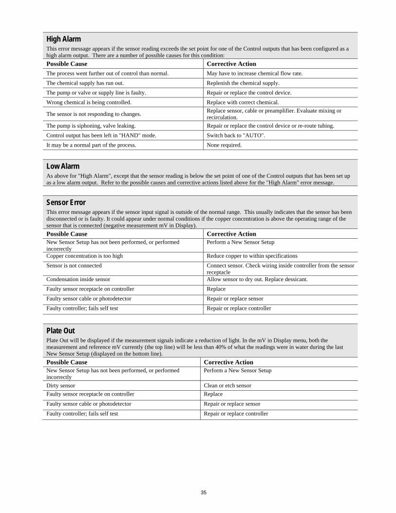
High Alarm This error message appears if the sensor reading exceeds the set point for one of the Control outputs that has been configured as a high alarm output. There are a number of possible causes for this condition:
Possible Cause Corrective Action
The process went further out of control than normal. May have to increase chemical flow rate.
The chemical supply has run out. Replenish the chemical supply.
The pump or valve or supply line is faulty. Repair or replace the control device.
Wrong chemical is being controlled. Replace with correct chemical.
The sensor is not responding to changes. Replace sensor, cable or preamplifier. Evaluate mixing or recirculation.
The pump is siphoning, valve leaking. Repair or replace the control device or re-route tubing.
Control output has been left in "HAND" mode. Switch back to "AUTO".
It may be a normal part of the process. None required.
Low Alarm As above for "High Alarm", except that the sensor reading is below the set point of one of the Control outputs that has been set up as a low alarm output. Refer to the possible causes and corrective actions listed above for the "High Alarm" error message.
Sensor Error This error message appears if the sensor input signal is outside of the normal range. This usually indicates that the sensor has been disconnected or is faulty. It could appear under normal conditions if the copper concentration is above the operating range of the sensor that is connected (negative measurement mV in Display).
Possible Cause Corrective Action New Sensor Setup has not been performed, or performed incorrectly
Perform a New Sensor Setup
Copper concentration is too high Reduce copper to within specifications
Sensor is not connected Connect sensor. Check wiring inside controller from the sensor receptacle
Condensation inside sensor Allow sensor to dry out. Replace dessicant.
Faulty sensor receptacle on controller Replace
Faulty sensor cable or photodetector Repair or replace sensor
Faulty controller; fails self test Repair or replace controller
Plate Out Plate Out will be displayed if the measurement signals indicate a reduction of light. In the mV in Display menu, both the measurement and reference mV currently (the top line) will be less than 40% of what the readings were in water during the last New Sensor Setup (displayed on the bottom line).
Possible Cause Corrective Action New Sensor Setup has not been performed, or performed incorrectly
Perform a New Sensor Setup
Dirty sensor Clean or etch sensor
Faulty sensor receptacle on controller Replace
Faulty sensor cable or photodetector Repair or replace sensor
Faulty controller; fails self test Repair or replace controller
36
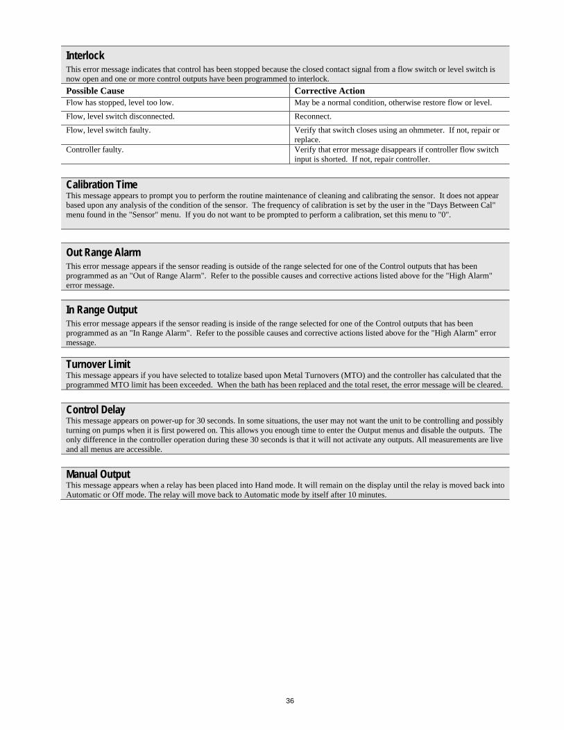
Interlock This error message indicates that control has been stopped because the closed contact signal from a flow switch or level switch is now open and one or more control outputs have been programmed to interlock.
Possible Cause Corrective Action Flow has stopped, level too low. May be a normal condition, otherwise restore flow or level.
Flow, level switch disconnected. Reconnect.
Flow, level switch faulty. Verify that switch closes using an ohmmeter. If not, repair or replace.
Controller faulty. Verify that error message disappears if controller flow switch input is shorted. If not, repair controller.
Calibration Time This message appears to prompt you to perform the routine maintenance of cleaning and calibrating the sensor. It does not appear based upon any analysis of the condition of the sensor. The frequency of calibration is set by the user in the "Days Between Cal" menu found in the "Sensor" menu. If you do not want to be prompted to perform a calibration, set this menu to "0".
Out Range Alarm This error message appears if the sensor reading is outside of the range selected for one of the Control outputs that has been programmed as an "Out of Range Alarm". Refer to the possible causes and corrective actions listed above for the "High Alarm" error message.
In Range Output This error message appears if the sensor reading is inside of the range selected for one of the Control outputs that has been programmed as an "In Range Alarm". Refer to the possible causes and corrective actions listed above for the "High Alarm" error message.
Turnover Limit This message appears if you have selected to totalize based upon Metal Turnovers (MTO) and the controller has calculated that the programmed MTO limit has been exceeded. When the bath has been replaced and the total reset, the error message will be cleared.
Control Delay This message appears on power-up for 30 seconds. In some situations, the user may not want the unit to be controlling and possibly turning on pumps when it is first powered on. This allows you enough time to enter the Output menus and disable the outputs. The only difference in the controller operation during these 30 seconds is that it will not activate any outputs. All measurements are live and all menus are accessible. Manual Output This message appears when a relay has been placed into Hand mode. It will remain on the display until the relay is moved back into Automatic or Off mode. The relay will move back to Automatic mode by itself after 10 minutes.
37
8.0 SERVICE POLICY The WCU Series Electrodeless Conductivity Controller has a 2-year warranty on electronic components and a 1-year warranty on mechanical parts (keypad, terminal strip and relays). We stock circuit boards for immediate exchange after we have isolated the cause of the problem. Factory authorized repairs that are received by next-day-air will be returned within 24 hours. Normal priority for returns is two weeks. Out of warranty repairs or circuit board exchanges are done on a flat fee basis after the warranty is expired.
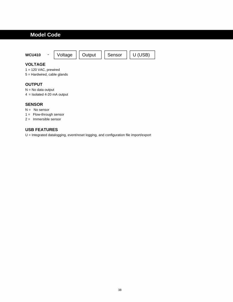
38
WCU410
VOLTAGE
1 = 120 VAC, prewired 5 = Hardwired, cable glands
OUTPUT N = No data output 4 = Isolated 4-20 mA output
SENSOR
N = No sensor 1 = Flow-through sensor 2 = Immersible sensor
USB FEATURES
U = Integrated datalogging, event/reset logging, and configuration file import/export
Model Code
Voltage Output Sensor U (USB) -

FIVE BOYNTON ROAD HOPPING BROOK PARK HOLLISTON, MA 01746 USA TEL: 508-429-1110 FAX: 508-429-7433 Web: www.walchem.com