w.b.mori ucla f.s.tsung ck. huang v.k.decyk d.bruhwiler techx d.dimitrov e.esarey lbnl
DESCRIPTION
UCLA. SciDAC plasma-based team:. W.B.Mori UCLA F.S.Tsung CK. Huang V.K.Decyk D.Bruhwiler TechX D.Dimitrov E.Esarey LBNL B.Shadwick G.Fubiani T.Katsouleas USC S.Deng. Advanced accelerator effort is highly leveraged: Big bang for the buck. Why and what is plasma-based acceleration. - PowerPoint PPT PresentationTRANSCRIPT

– W.B.Mori UCLA• F.S.Tsung• CK. Huang• V.K.Decyk
– D.Bruhwiler TechX• D.Dimitrov
– E.Esarey LBNL• B.Shadwick• G.Fubiani
– T.Katsouleas USC• S.Deng
SciDAC plasma-based team:
UCLA

Advanced accelerator effort is highly leveraged:Big bang for the buck
Institution 2002 2003
UCLA 60K (125K) 70K (144K)
Tech-X 50K 60K
USC 20K 25K
LBNL 20K 25K

Why and what is plasma-based acceleration
Long term future of High-Energy physics requires the need for new high-gradient technology
Gradients from 1GeV/m to 100 TeV/m are possible from relativistic plasma waves

Experimental progress
0
1
2
3
4
5
6
7
1930 1940 1950 1960 1970 1980 1990 2000 2010
LivingstonCurrent statusfuture
Year
RAL/IC/UCLA/LULI NRL, UM
UCLA
UCLA Port J. LLNL/UCLA
?
SLAC/USC/UCLA/LBL
LEP
E-164/ORION
E-162
LBNL

Physical Principles of the PlasmaPhysical Principles of the Plasma Wakefield Accelerator Wakefield Accelerator
• Space charge of drive beam displaces plasma electrons
• Transformer ratio
• Wake Phase Velocity = Beam Velocity (like wake on a boat)
• Plasma ions exert restoring force => Space charge oscillations
E Ezacc dec beam. .
• Wake amplitude ∝ N b zσ 2 ( )fornz p
o2
1σ λ≈ ∝
++++++++++++++ ++++++++++++++++
----- --- ----------------
--------------
--------- ----
--- -------------------- - --
---- - -- ---
------ -
- -- ---- - - - - - ------ - -
- - - - --- --
- -- - - - - -
---- - ----
------
electron beam
+ + + + + + + + + + ++ + + + + + + + + + + + + + ++ + + + + + + + + + + + + + +
+ + + + + + + + + + + + + + +-
- --
--- --
EzEz

Laser Wake Field Accelerator(LWFA)
A single short-pulse of photons
evolves to
Self Modulated Laser Wake Field Accelerator(SMLWFA)
Raman forward scattering instability
Plasma Beat Wave Accelerator(PBWA)
Two-frequencies, i.e., a train of pulses
Plasma Wake Field Accelerator(PWFA)
A high energy electron bunch
Concepts For Plasma Based Accelerators
Pioneered by J.M.Dawson

Mission
Develop high fidelity parallelized software (at least two distinct codes): primarily particle based models
Model the full-scale of current experiments ~100MeV -1GeV
Enable full-scale modeling of 100+ GeV plasma-based colliders
Transfer plasma models to conventional accelerator modeling
Enable scientific discovery

A goal is to build a virtual accelerator:
A 100 GeV-on-100 GeV e-e+ Collider
Based on Plasma Afterburners
Afterburners
3 km
30 m

Beam-driven wake* Fully ExplicitΔz ≤ .05 /cωp
Δy, Δx ≤ .05 /cωp
Δt ≤ .02 /cωp
# grids in z ≥350
# grids in x , y ≥150# s teps ≥2 x 10 5
Npa rticles ~.25-1. x 108 (3D)
Pa rticles x s teps ~.5 x 1013 (3D) - ≥ 10,000 h rsa t ~.1 GFlops
*Lase r-driven GeV st age re quires on the o rder of (ωo/ωp)2=1000 x longer , however , the the res olution ca n usua lly be re laxed.
Computational challenges for modeling plasma-based acceleration
(1 GeV Stage): 1000hours/GFlop

Parallel Full PIC OSIRIS Vorpal/OOPIC
Parallel quasi-static PIC quickPIC
Fluid (quasi-static and full)
To model a plasma stage including beam loading will require particle models
Community of parallel PIC codes and algorithms exist:PIC codes make “minimal” physics approximations

• Maxwell’s equations for field solver
• Lorentz force updates particle’s position and momentum
Interpolate to particles
Particle positions
Lorentz Force
push
partic
les weight to grid
z vi i,
ρn m n mj, ,,r
dpdt
E v B cr r r r= + ×
r rE Bn m n m, ,,
Δt
Computational cycle (at each step in time)
What Is a Fully Explicit Particle-in-cell Code?
Typical simulation parameters:~107-109 particles ~1-100 Gbytes~104 time steps ~102-104 cpu hours

Multiple codes Benchmarking against each other and against reduced numerical
models and analytic theory Validation against experiment
E-162/E-164 L’OASIS
Modeling future experiments E-164/E-164x L’OASIS
A path towards a virtual accelerator
SCIENTIFIC DISCOVERY ALONG THE WAY
SciDAC collaborative approach
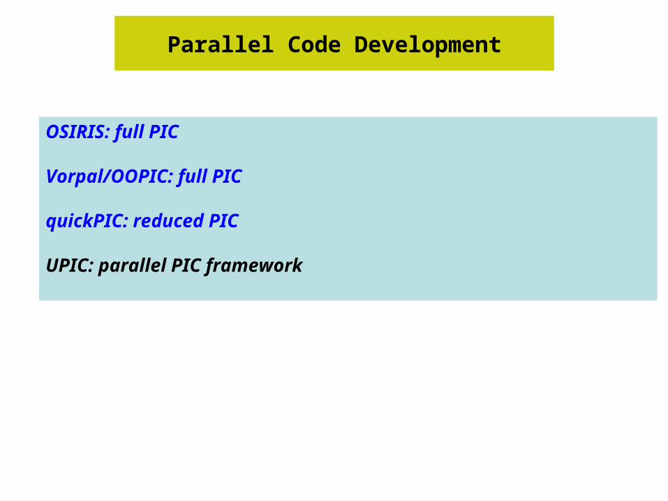
Parallel Code Development
OSIRIS: full PIC
Vorpal/OOPIC: full PIC
quickPIC: reduced PIC
UPIC: parallel PIC framework

OSIRIS.frameworkBasic algorithms are mature and well tested
• Fully relativistic
• Choice of charge-conserving current deposition algorithms
• Boris pusher for particles, finite field solver for fields
• 2D cartesian, 2D cylindrical and 3D cartesian
• Arbitrary particle initialization and external fields
• Conducting and Lindmann boundaries for fields; absorbing, reflective, and thermal bath for particles; periodic for both
• Moving window
• Launch EM waves: field initialization and/or antennas
• Launch particle beam
• particle sorting and ion subcycling
• Extended diagnostics using HDF file output:–Envelope and boxcar averaging for grid quantities–Energy diagnostics for EM fields–Phase space, energy, and accelerated particle selection diagnostics for particles
UCLA

Ionization modules are being added:Both in 2D and 3D
Ionization modules were added in 2D (slab and cylindrical) and 3D
Monte Carlo impact ionization model was used: particles are born at rest
Monte Carlo field ionization model was used: particles are born at rest
Various cross sections and tunnel rates are being tested: benchmarking with the help of OOPIC

Effort was made to improve speed and maintaing parallel efficiency:
2D 128x128 with 16 particles/cell per processor and Vth=.1c
CPU#
Speed
s/ps
Push
%
BCpart BCcurr Field
Solve
BC Field
other Efficiency
1 2.1 95 4.2 .03 .56 .03 .19 100
4 2.13 95 3.89 .09 .59 .1 .31 99.48
16 2.2 92.8 4.91 .53 .71 .38 .68 95.82
64 2.3 89.3 6.87 1.28 .57 1.09 1.09 91.82
256 2.29 88.7 6.97 1.29 .55 1.39 1.15 92.16
512 2.37 85.2 7.42 1.27 .54 1.87 3.72 88.52
1024 2.45 85
Speed in 3D: 3.2s/ps with 80%efficiency on 512 processors And 60% on 1024 processors

Domain Decompositions
OSIRIS Algorithms
1D Decomposition 2D Decomposition 3D Decomposition
• OSIRIS currently allows distribution of the simulated space into evenly partitioned domains along any axis
• next steps in extending the code will be to introduce an uneven distribution of domains and dynamic load balancing: follow concepts in PLIB

VORPAL – Multi-dimensional hybrid code
• Achieves great flexibility with negligible run-time penalty– Multi-dimensional (2D or 3D, with Cartesian geometry)
• can switch from 2D to 3D with same code and input file• enabled by “generic programming” paradigm of C++
– Runs in serial or parallel (using MPI)• flexible 2D and 3D domain decomposition• good scaling up to 500 processors has been demonstrated
– Cross-platform: Linux, IBM SP, Windows, Solaris
• Combines multiple fluid and PIC algorithms seamlessly– finite-difference time domain (FDTD) on structured Yee mesh– Particle-in-Cell
• standard Boris particle push• charge-conserving current deposition
– Cold fluid algorithms• multiple flux-corrected transport (FCT) algorithms for positive
density

VORPAL’s flexible domain decomposition allowsfull load balancing, good scaling
General decomposition allows load balancing
VORPAL Parallelism
0
0.1
0.2
0.3
0.4
0.5
0.6
1 2 4 6 8
# processors
Surf/Vol & Speed
Surface/Volume
Speed
Domains down to 45x25x25 with 140k particles, 20% surf/vol
• Beowulf: 1.2GHz Athlons, fast ethernet
• Have seen good scaling on 128-256 SP processors
Set theory based messaging

Moving Ionization Algorithms from OOPIC to VORPAL
• OOPIC is a 2-D (x-y & r-z) electromagnetic PIC code– Includes Monte Carlo collision (MCC) models
• These enabled rapid implementation of relativistic electron-impact and field-induced tunneling ionization algorithms
– Uses MPI for parallel computing (1-D domain decomposition)
• These ionization algorithms are being ported to VORPAL
• OOPIC ionization algorithms have been validated against data from the l’OASIS lab at LBNL:

quickPIC• Quasi-static approximation: driver evolves on a much
longer distances than wake wavelength· Frozen wakefield over time scale of the bunch length
·
· => and/or xR >> σz (very good approximation!)
Beam
Wake
UCLA

Basic equations for approximate QuickPIC
• Quasi-static or frozen field approximation converts Maxwell’s equations into electrostatic equations
(1c2
∂2
∂t2 −∇2)A =4πc
j
(1c2
∂2
∂t2 −∇2)φ =4πρ
−∇⊥2A =
4πc
j
−∇⊥2φ =4πρ
Maxwell equations in Lorentz gauge Reduced Maxwell equations
j =jb +je ≈jb =cρbˆ z • )ˆ( // zA=A
Local-- at any z-slice depend only on ρj at that slice!
φ,A=ϕ,A(z−ct)
Quasi-static approx.
• Ψ =φ −A//
Forces:
plasma: Fe⊥ =−e∇⊥φ
beam: Fb⊥ =−e∇⊥Ψ

2-D plasma slab
Beam (3-D)Wake (3-D)
1. initialize beam
2. solve ∇⊥2ϕ =ρ, ∇⊥
2ψ =ρe ⇒ Fp,ψ
3. pushplasma, storeψ
4. stepslabandrepeat2.
5. useψ togiantstepbeam
QuickPIC loop (based on UPIC):

Parallelization of QuickPIC
zy
x
Node 3 Node 2 Node 1 Node 0
x
y
Node 3
Node 2
Node 1
Node 0

Benchmarking
Full PIC: OSIRIS and OOPICparticle driverslaser drivers
Full PIC vs. quasi-static PIC: OSIRIS and quickPICparticle drivers
PIC vs. Fluid: Laser driversparticle drivers
Simulation against theorytrapping mechanism in all optical injection

quickPIC vs. OSIRISPositron driver
-0.08
-0.06
-0.04
-0.02
0
0.02
0.04
0.06
0.08
-10 -5 0 5 10
OsirisStandard QuickPICFull QuickPIC
ζ ( /cωp)
-0.2
-0.15
-0.1
-0.05
0
0.05
0.1
0.15
0.2
-3 -2 -1 0 1 2 3
Full QuickPICStandard QuickPICOsiris
ζ ( /cωp)
Lon
gitu
dina
l Wak
efie
ld (
mcω
p/e)
Focu
sing
Fie
ld (
mcω
p/e)
Plasma density = 2.1E14 cm-3, Beam Charge = 1.8E10 e+
Head Tail
Wakefield and focusing field from QuickPIC agree well with those from Osiris, and it is >100 times faster!.

Benchmarking (2D) field ionization routines:OOPIC and OSIRIS
-30
-20
-10
0
10
20
30
-30
-20
-10
0
10
20
30
0 0.0002 0.0004 0.0006 0.0008 0.001 0.0012
Benchmark OSIRIS and OOPIC
Ez(Gv/m)--OSIRIS
Ez(Gv/m)--OOPIC
Z(m)

Modeling experiments:Code validation and interpretation of physics
Plasma wakefield accelerator(PWFA)E-157/E-162
electron acceleration/focusingpositron acceleration/focusing
Laser wakefield accelerator(LWFA/SMLWFA)L’OASIS(LOA)
Blue shiftsself-trapped electrons

Located in the FFTB
e- or e+
N=2·1010
σz=0.6 mmE=30 GeV
IonizingLaser Pulse
(193 nm)Li Plasma
ne≈2·1014 cm-3
L≈1.4 m
CerenkovRadiator(Aerogel)
Streak Camera(1ps resolution)
Quad+BendMagnets
X-RayDiagnostic
Optical TransitionRadiators Dump
12 m
∫Cdt
E-162 Plasma Wakefield Expt.
FFTB
UCLA

10 TW Ti:sapphire
Laser-plasma accelerator R&D at l’OASIS lab
• Test bed for R&D concepts towards 1 GeV module of a laser accelerator and applications• Facility includes 10 TW, 50 fs laser system @ 10 Hz (100 TW under development)• Laser, plasma and beam diagnostics; radiation shielded experimental bays• Training ground for students and postdocs
100 TW Ti:sapphireUnder construction
Low energy100 mrad
High energy< 10 mrad
Electrons
Laser beams
Shielded target room
Gasjet
Laser beam
Parabolic mirror
Mirror
CCDebeam

Excellent agreement between simulation and experiment of a 28.5 GeV positron beam which has passed through a 1.4 m PWFA
OSIRIS Simulation Prediction:Experimental Measurement:
Peak Energy Loss64 MeV
65±10 MeV
Peak Energy Gain78 MeV
79±15 MeV
5x10⁸ e+ in 1 ps bin at +4 ps
Head Tail Head Tail
OSIRIS E162 Experiment

Moving Ionization Algorithms from OOPIC to VORPAL
• OOPIC is a 2-D (x-y & r-z) electromagnetic PIC code– Includes Monte Carlo collision (MCC) models
• These enabled rapid implementation of relativistic electron-impact and field-induced tunneling ionization algorithms
– Uses MPI for parallel computing (1-D domain decomposition)
• These ionization algorithms are being ported to VORPAL
• OOPIC ionization algorithms have been validated against data from the l’OASIS lab at LBNL:

•Simulation Parameters–Laser:
• a0 = 3• ωl/ωp = 3 to 15
–Particles• 1x2x2 particles/cell• 200 million total
•The parameters are similar to those at LOA and LBNL
Full scale 3D LWFA and SMLWFA simulations:L’OASIS parameters
2000 cells80 m
300 cells80 m
300 cells80 m
State-of- the- art ultrashort laser pulse
λ0 = 800 nm, Δt = 35 fs
I = 1x10¹⁹ W/cm-2, W =7 m
Laser propagation
Plasma Backgroundne = 1.38-17 x1019 cm-3
Simulation ran for ~10000 time steps
(~3 Rayleigh lengths)
Simulation ran for ~10000 time steps
(~3 Rayleigh lengths)

103
104
105
106
107
108
109
1010
0 20 40 60 80 100 120
Energy Spectra of Fast Electrons
10% nc, T
e=5.3 MeV
5% nc, T
e=9.99MeV
2% nc, T
e=14.3 MeV
Electron Energy (MeV)
γmax
=115MeV
γmax
= 83MeVγ
max= 60MeV
f(E)
Electron spectra is consistent with results fromLOA
UCLA

In 3D the electrons have an asymmetric spot size in the plasma:laser effects acceleration
what happens when they exit the plasma? (Electrostatic PIC combined with semi-
analytical model: Fubiani)
p3 vs. p1 p1 vs. x3 p3 vs. x2
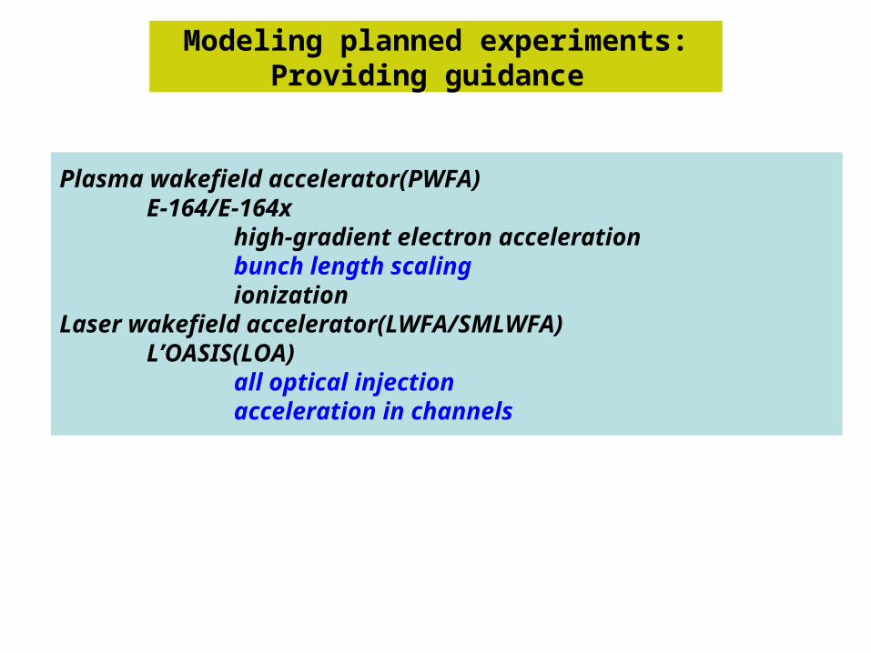
Modeling planned experiments:Providing guidance
Plasma wakefield accelerator(PWFA)E-164/E-164x
high-gradient electron accelerationbunch length scalingionization
Laser wakefield accelerator(LWFA/SMLWFA)L’OASIS(LOA)
all optical injectionacceleration in channels
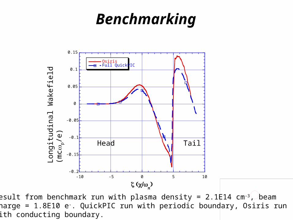
Benchmarking
-0.2
-0.15
-0.1
-0.05
0
0.05
0.1
0.15
-10 -5 0 5 10
OsirisFull QuickPIC
ζ ( /c ωp)
Lon
gitu
dina
l Wak
efie
ld (
mcω
p/e)
Result from benchmark run with plasma density = 2.1E14 cm-3, beam charge = 1.8E10 e-. QuickPIC run with periodic boundary, Osiris run with conducting boundary.
Head Tail

Bunch length scaling: E164 and Afterburner parameters
0.1
1
10
100
1000
0 100 200 300 400 500 600 700
E_spike(GV/m)
E_useful(GV/m)
E_decel(GV/m)
E_2sigma(GV/m)
Linear_theory (GV/m)
E_spike(GV/m)
sigma_z(micron)
Sigma_r=25 micron

0
200
400
600
800
1000
1200
1400
0 2 4 6 8 10
Energy Gain vs. Distance
γ
( )Distance mm
Pulse distortion leads to a second phase of acceleration

Modeling a 5TW 50 fs laser propagating through 60 Raylengths in a plasma channel

Fluid Code: Laser pulse in a channel• 2D Fluid-Maxwell Code
• Relativistic and nonlinear• No averaging: laser oscillations resolved• Moving window
• Detailed comparisons to particle codes in progress
• Example: Laser pulse in a plasma channel• Wakefield generation• Laser pulse energy depletion• Frequency red-shifting
• Parameters: Achievable at the l’OASIS lab

Longitudinal Electric Field vs (x,z)
Density vs (x,z)
ωpt = 240 (0.9 mm)
Laser Wakefields in Plasma ChannelBenchmarking against PIC is beginning
Nonlinear plasma wave
Front
Back
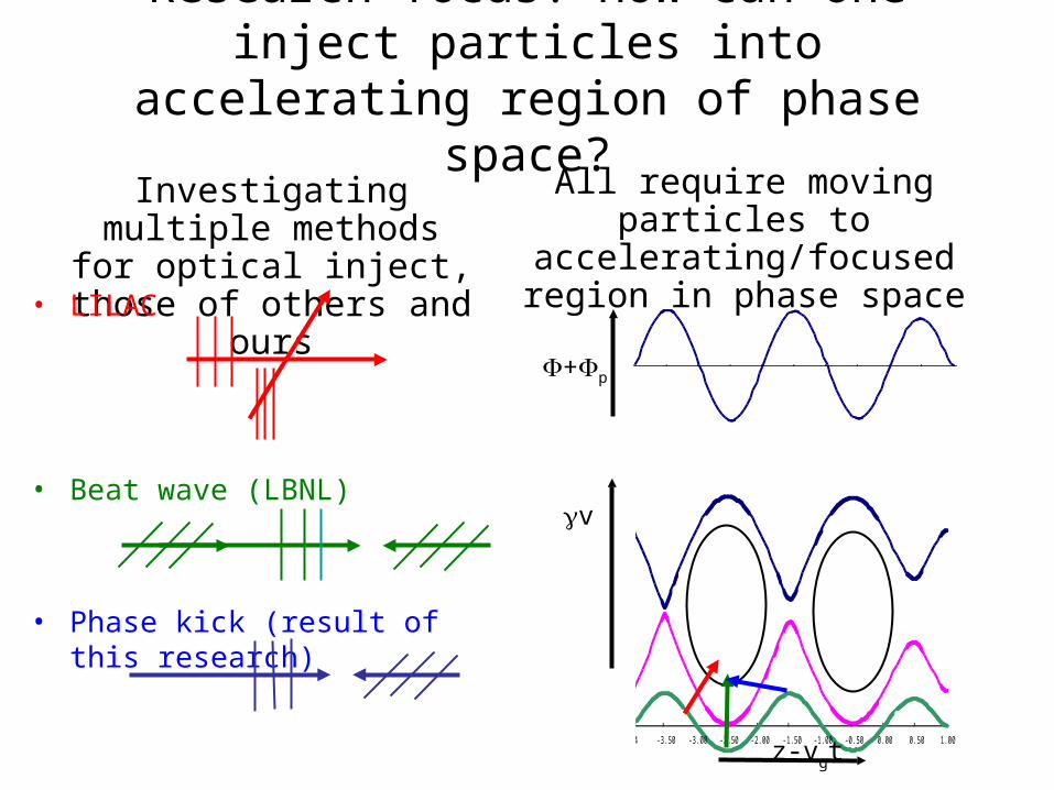
Research focus: How can one inject particles into accelerating region of phase space?
-4 -3.50 -3.00 -2.50 -2.00 -1.50 -1.00 -0.50 0.00 0.50 1.00
-1.000
-0.500
0.000
0.500
1.000
1.500
2.000
2.500
3.000
3.500
4.000
4.500
-4 -3.50 -3.00 -2.50 -2.00 -1.50 -1.00 -0.50 0.00 0.50 1.00
z-vgt
+p
γv
Investigating multiple methods for optical inject, those of others and ours
All require moving particles to accelerating/focused region
in phase space• LILAC
• Beat wave (LBNL)
• Phase kick (result of this research)

Discovery: The expansion of the focusing region for nonlinear wakes improves trapping mechanism
• Focusing region greatly expanded
• Focusing trajectories exists for positive potential
• Consequence: small phase kick can trap particles
Ey

Simulations show that focusing collimation forms the beam
• Region of negative potential energy is focusing
• Region of negative phase relative to minimum is accelerating
• Particles stay in this region while accelerating provided they are inside the F/D transition invariant curve
• Place large population of particles just inside this curve and dynamics forms beam after 1/4 of synchrotron (bounce) oscillation
y
px/c
Laser propagates along x
66
x
Overplotting shows beams worse than they areSimulations showing secondary beams

Beyond planned experiments:Afterburner modeling
Nonlinear wakespreformedself-ionized
Nonliear beamloadingStability: hosingFinal focusing

OOPIC shows that a PWFA e- driver can ionize neutral Li
• OOPIC simulations show that tunneling ionization plays a key role in the PWFA afterburner concept– The self-fields of the bunch can ionize Li or Cs– High particle density (i.e. large self-fields) is required to drive a strong wake
• In Li, a shorter afterburner drive beam could ionize the plasma by itself– This approach would greatly simplify beam-driven wakefield accelerators– σr=20 m; σz=30 m; 2x10¹⁰ e- in the bunch; E0=11.4 GV/m
• We need to model evolution of the drive beam with TI effects included

1+1 ≠ 2:Superpostion cannot be used for nonlinar beamloading
2nd beam charge density
1st beam charge density
Linear superposition
Nonlinear wake
Nonlinear wake

Hosing can be studied for afterburner
parameters using quickPIC
Electron drive beam hoses as it propagate over a long distance in the plasma
3D image of the plasma charge density under blow-out regime
t = 0 t = 64,800 (1/ωp)
++ ++ ++ ++ ++ ++ + ++ + ++ ++ ++ ++ ++ ++ ++
-- -- -- - ---- -- --- ---- ----
- - -- - - - ---Er --
---------- --- --- - - - -- - -- -- -----------
-
----------
-- --- --
-- ---------- --- - ---
----- ----
-- ------
- - - --- - --
-- - ---
++++++++++++++++++++++++++ +++++++++++++++ +++++++++++++++
-
---
-- ---
EzEz
Focusing fieldAcceleration field

Connections to other areas in accelerator modeling
electron-cloud modeling using plasma codes: quickPIC
Beam-Beam codes use parts of UPIC:UPIC is a parallel PIC Framework (it incluces PLIB)which is a general computer science component to this project

Plasma Modeling of Electron Cloud Instability
• e-cloud is a non-neutral plasma -- well suited to plasma wakefield PIC models
• Previous cloud models-- single node workstations
– treat cloud as a single kick once per orbit
– No image forces from beam pipe
– No benchmarks-- poor agreement with experiments
+
-
SynchrotronRadiation
SecondaryEmission
Circularmachine
Positron Bunch• E-cloud formation(Positron): synchrotron radiation+secondary emission• E-cloud formation(Proton): halo scraping+secondary • Observed in circular accelerators like:CERN-SPS and SLAC-PEP and KEKB • Major concern in LHC Design,
Fermilab upgrade

Longitudinal wake vs. zunphysical divergence!
Transverse and Longitudinal wakes vs. z
(From QuickPIC)
Code Comparison
(From HEAD-TAIL)

QuickPIC Model of Beam & Cloud Evolution Through 40Km of SPS Proton Ring at CERN (6 turns)
Beam Density
Cloud Density
Recently 700km (100 turns) was modeled

Connections with ISIC’s
APDEC:Parallel Poisson solvers for elliptical conductors
for applying quickPIC to e-cloudModeling gas jets
Laser-plasma experiments

Strong educational component:Includes those directly funded and those who are
closely coupled to the effort
Graduate students:CK.Huang, W.Lu, R.Narang (UCLA)S.Deng, A.Z.GhalamG.Fubiani (LBNL)J.Regele (UofColorado)
Young researchers:F.S.Tsung (UCLA)C.Nieter (UofColorado)R.Giaconne

SciDAC has greatly accelerated progress:Collaboration, computational resources, applied math
Code development:benchmarking of codes against each othercooperation of ionization routine developmentrapid construction of new codes:
VorpalquickPIC for e-cloud
Collaboration in science:electron-cloudall-optical injection collaborative effort
Enabling computational resources :Full-scale modeling of SMLWFA experimentsFull-scale modeling of E-162Modeling of LWFA in a channel