waygood ch11 web.indd
TRANSCRIPT
CHAPTER
Elec
tric
al S
cien
ce fo
r Tec
hnic
ians
. 978
-1-1
38-8
4926
-6 ©
Adr
ian
Way
good
. P
ublis
hed
by T
aylo
r &
Fra
ncis
. All
right
s re
serv
ed.
Transformers 3: connections
Further reading
Objectives
On completion of this chapter, you should be able to
1. construct a phasor diagram for a three-phase transformer under load, given its primary and
secondary connections, showing all phase and line voltages and currents.
11
Now that we have learnt about transformer polarities and terminal markings, we are in a position to move on and learn how to construct a complete phasor diagram for any three-phase transformer.
Constructing a complete phasor diagram that represents all the primary and secondary line and phase voltages and line and phase currents associated with any particular three-phase transformer connection can be somewhat confusing, unless we follow a logical sequence of steps.
The diagram, below, shows the correct sequence to be followed whenever we wish to construct a complete phasor diagram for a three-phase transformer supplying a load. This particular diagram shows a star-delta transformer, but the sequence and method applies to any transformer connection.
Examine the diagram carefully, while noting the following points:
XX the voltages are determined by the supply, whereas the currents are determined by the loadXX phase values are always considered before line valuesXX completed phasors should always reflect the normal (or ‘positive’) phase
sequence: A-B-C-AXX high-voltage terminals are identified with upper-case letters (A-B-C), while low-
voltage terminals are identified with lower-case letters (a-b-c).
1

11 Transformers 3: connections
2
So, as you can see from the diagram, to construct the voltage phasors, we work from the supply towards the load (because it’s the supply that determines the voltages) while, to construct the current phasors, we work from the load back towards the supply (because it’s the load that determines the currents).
Before proceeding, you may wish to review the chapter on three-phase connections in the companion book, An Introduction to Electrical Science.
To simplify our circuit diagrams and reduce clutter, we’ll use the ‘dot convention’ polarity markings, rather than the British Standard (i.e. A1–A2, a1–a2, etc.). Remember that all voltages measured from a polarity mark (dot) to a non-polarity mark (no dot) are in phase with each other.
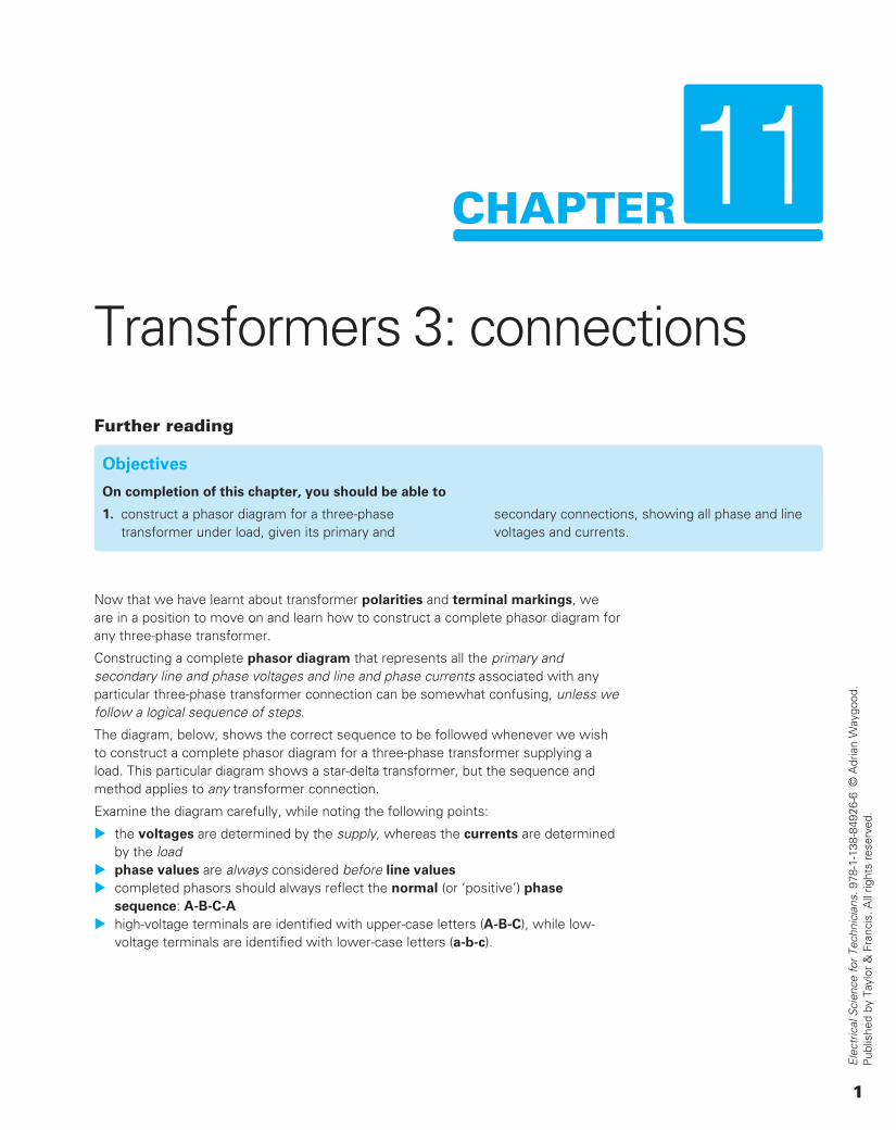
So, let’s learn how to apply the sequence described above, by constructing a complete phasor diagram for the following transformer connection: a star-delta, three-phase, step-down transformer bank, supplying a balanced, purely resistive, delta-connected load, and whose terminals are marked as shown. We’ll assume a step-down transformation ratio of 2:1. And, remember, it’s very important we always observe the transformers’ polarity markings (‘dot convention’), which, in the following example indicates that we are working with an ‘additive’ transformer.
Figure 11.33
11 Transformers 3: connections
11
3
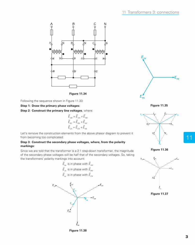
Following the sequence shown in Figure 11.33:
Step 1: Draw the primary phase voltages:
Step 2: Construct the primary line voltages, where:
= +
= +
= +
E E E
E E E
E E E
AB AN NB
BC BN NC
CA CN NA
Let’s remove the construction elements from the above phasor diagram to prevent it from becoming too complicated:
Step 3: Construct the secondary phase voltages, where, from the polarity markings:
Since we are told that the transformer is a 2:1 step-down transformer, the magnitude of the secondary phase voltages will be half that of the secondary voltages. So, taking the transformers’ polarity markings into account:
E E
E E
E E
is in phase with
is in phase with
is in phase with
ba AN
cb BN
ac CN
Figure 11.34
Figure 11.35
Figure 11.36
Figure 11.37
Figure 11.38

11 Transformers 3: connections
4
But, in order to maintain the normal phase sequence of a-b-c-a, it is necessary to reverse the phasors E E, ,ba cb and E ,ac thus giving E E, ,ab bc and Eca:
Figure 11.39
Again, let’s remove the construction phasors, in order to prevent the phasor diagram becoming too complicated:
Figure 11.40
As you can see, by taking the transformers’ polarity markings into account, the secondary phase voltages are in antiphase (180° out of phase) with their corresponding primary with their primary phase voltages, which is what you would expect for an additive-polarity transformer.
Step 4: Construct the secondary line voltages:
Since the secondary windings of this particular transformer bank are connected in delta, its line voltages are exactly the same as its phase voltages. So, for this transformer connection, this step has already been achieved in Step 3.
It’s also worth noting that these secondary-line voltages lag their corresponding primary line voltages by 210 electrical degrees, which means that the connection’s angular displacement is 210°.
Step 5: Draw the load’s phase voltages.
As both the load and the transformers’ secondary windings are each connected in delta, they both share the same line voltages, and the load’s phase voltages must be

11 Transformers 3: connections
11
5
exactly the same as the transformers’ phase voltages. So we don’t need to complete this particular step.
Step 6: Draw the load’s phase currents:Before we do this, we need to consider the following:
Figure 11.41
The phase voltage, Eab, appearing across its corresponding load will result in a phase current, Iab ; through that load; similarly, the phase voltage, Ebc, will result in a phase current, Ibc; and the phase voltage, Eca, will result in a phase current, Ibc
.
Since we are told that the load is purely resistive, the load’s phase currents must be in phase with their corresponding phase voltages.
Figure 11.42
Step 7: Draw the secondary line currents:
The secondary line currents are, of course, common to both the load and the secondary of the transformer bank, where:

11 Transformers 3: connections
6
= +
= +
= +
I I I
I I I
I I I
a ab ac
b bc ba
c ca cb
Figure 11.43
Step 8: Draw the secondary phase currents:
Here, we have to break the rule of ‘drawing the phase quantities before the line quantities’ because, in this case the line currents are determined by the load, so the line currents will determine the transformers’ secondary phase currents.
The secondary line currents are the phasor-sum of the corresponding phase currents in the transformer bank’s secondary windings. Since, in a balanced system, the phase currents lead the line currents by 30°, it is clear that these currents must correspond exactly to the load’s phase currents, Iab, Ibc, and Ica, which we have already constructed in Step 6.
Figure 11.44
Step 9: Construct the Primary Phase Currents:
Before we proceed with this step, it’s necessary for us to pause and consider the following points. Firstly, let’s consider any single-phase transformer supplying a load:Figure 11.45

11 Transformers 3: connections
11
7
Let’s assume that the secondary current flows from point ‘a’ to point ‘b’ through the load and, so, it must flow from point ‘b’ to point ‘a’ through the secondary winding itself.
So the question is, should this current be labelled Iab , or should it be labelled Iba?
Of course, it’s exactly the same current, so it obviously can’t be both Iaband Iba! So which is it?
The answer is straightforward. Double-subscript notation always indicates the direction of the current through the load, never through its source. And, so, we must identify the current as Iab , not Iba.
Now, let’s consider Figure 11.46, which illustrates another very important rule: whenever a current flows towards the polarity marking on one side of a transformer, the corresponding current always flows away from the polarity marking on the other side of the transformer.
Figure 11.46
Now, let’s apply these rules to our example… (Figure 1.47).
Figure 11.47

11 Transformers 3: connections
8
From the schematic diagram in Figure 11.47, we can see that:
Table 11.3
Within the load, the phase currents flow: Within the secondary winding, the phase currents flow:
• from ‘a’ to ‘b’.
• from ‘b’ to ‘c’.
• from ‘c’ to ‘a’.
• from ‘b’ to ‘a’.
• from ‘c’ to ‘b’.
• from ‘a’ to ‘c’.
If we now examine the phase currents flowing in the secondary windings, it can be seen that each current must enter its particular winding at a polarity-marked terminal, from which we can deduce that, on the primary side, the corresponding primary phase current must be leaving from its polarity-marked terminal.
So the primary phase currents must be identified as being: I I I, , andNA NB NC , and must,
therefore, be 180° out of phase with the primary phase voltages, E E E, , andAN BN CN , as shown in the following illustration:
Figure 11.48
Step 10: Draw the Primary Line Currents
As the primary windings are connected in star (wye), the primary line currents are identical to the primary phase currents:
= = =I I I I I I; ; and ;A AN B BN C CN .
…and, so, the phasor diagram is complete.
Figure 11.49