watermarking three-dimensional polygonal models …masuda/papers/isac98.pdf · watermarking...
TRANSCRIPT
Page 1
Watermarking Three-Dimensional Polygonal ModelsThrough Geometric and Topological Modifications
Ryutarou Ohbuchi, Hiroshi Masuda, Masaki Aono
[email protected], [email protected], [email protected]
IBM Tokyo Research Laboratory
1623-14 Shimo-tsuruma, Yamato-shi
Kanagawa, 242, Japan
Manuscript first received March 1, 1997; revised July 15, 1997.
Abstract
This paper discusses techniques for embedding data into three-dimensional (3D) polygonal models
of geometry. Given objects consisting of points, lines, (connected) polygons, or curved surfaces, the
algorithms described in this paper produce polygonal models with data embedded into either their vertex
coordinates, their vertex topology (connectivity), or both. Such data embedding can be used, for example,
for copyright notification, copyright protection, theft deterrence, and inventory of 3D polygonal models.
A description of the background and requirements is followed by a discussion of where, and by what
fundamental methods, data can be embedded into 3D polygonal models. The paper then presents several
data-embedding algorithms, with examples, based on these fundamental methods. By means of these
algorithms and examples, we show that the embedding of data into 3D polygonal models is a practicable
technique.
Keywords: Geometric modeling, three-dimensional computer graphics, copyright protection, data
embedding, steganography, data hiding, digital watermarking, digital fingerprinting.
1. Introduction
The proliferation of digital media such as the Internet and CD-ROMs has made it is to duplicate,
distribute, and modify various kinds of digital contents, including images, texts, movies, audio data, and
recently three-dimensional (3D) models. At the same time, this ease of manipulation has also prompted
unauthorized duplication and distribution of valuable contents.

Page 2
One way of addressing this problem is to add watermarks to the objects in which contents are stored.
Watermarks are structures containing information that are embedded in a data object (e.g., an image) in
such a way that they do not interfere with its intended use (e.g., viewing). They can be used, for example,
to deter theft, to notify users of how to contact the copyright owner for payment of licensing fees, to
discourage unauthorized copying, or to take inventory. The technology associated with watermarks in
this sense is called steganography, data hiding, (digital) watermarking, data embedding, or
fingerprinting.
This paper presents fundamental techniques and algorithms for embedding data into 3D models of
geometry. Realistic applications of data embedding would require more sophisticated features, such as
the provision of security through the use of encryption. However, a set of basic data embedding
techniques presented in this paper serve as a foundation for methods adapted to the needs of more
realistic applications.
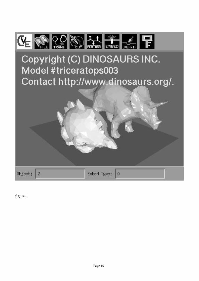
Figure 1 shows an example of embedding data into polygonal models of dinosaurs using an
algorithm described in Section 3.2. Each dinosaur model is marked with a distinct message. The
message embedded in the triceratops model, “Copyright (C) DINOSAURS INC. <CR> Model
#triceratops003 <CR> Contact http://www.dinosaurs.org/.”, can be extracted and displayed by clicking
on the model while using a 3D model browser enhanced with the extracting capability. Such messages
can be used, for example, to automatically connect the browser to a license server on the Internet to
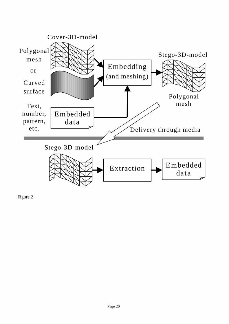
collect license fees.
In this paper, the addition of a watermark is called embedding (or watermarking), and the retrieval
of the information encoded in the watermark for perusal is called extraction, as illustrated in Figure 2.
The object in which the information is embedded is called cover-<datatype>, the object with the
watermark is called stego-<datatype>, and the information embedded is called embedded-<datatype>,
following recommendations in [Pfitzmann96]. The suffix “<datatype>” varies according to the types of
data such as image, text, or 3D model. For example, a text is embedded in a cover-3D-model to produce
a stego-3D-model with embedded text.
The remaining part of this paper is organized as follows. The rest of Section 1 presents a brief
review of related work. Section 2 first discusses requirements, followed by fundamental methods for
embedding data in 3D models. These fundamental methods are combined to create several embedding
algorithms, described in Section 3. We conclude with a summary and some remarks on possible
directions for future work.
Page 3
1.1. Related work
Data embedding has previously been studied for still images, movie images, audio data, and texts
[Tanaka90, Walton95, Cox95, Braudway96, O’Ruanaidh96, Smith96, Zhao96, Hartung97]. In the case
of 3D geometric models, the comment and annotation capabilities of scene description formats, such as
the Virtual Reality Modeling Language (VRML) [ISO96], have been the primary means of adding
information. However, these comments and annotations can be easily removed, either intentionally or
unintentionally. For example, programs for converting from one 3D model format to another often
remove comments and annotations. Consequently, comments and annotations cannot meet most of the
requirements of watermarks.
2. Fundamentals of watermarking 3D models
2.1. Embedding requirements
While each application of data embedding into 3D models has its own set of requirements, the
following three requirements are common to a majority of application scenarios.
Unobtrusive: The embedding must not interfere with the intended use of a model, such as viewing. One
published example of image watermarking [Braudway96] used the visibility of the watermarks to good
advantage, but in most applications, the watermarks must be unnoticeable in terms of the model’s
intended use.
Robust: Robustness is crucial to the success of data embedding. Making the watermark indestructible is
not a trivial problem. Note that this is different from making a message in the watermark unreadable.
With complete knowledge of how watermarks are embedded, any watermarks can theoretically be
removed. With partial knowledge (e.g., the knowledge of the basic algorithm), the removal must be
difficult enough so that it either interferes with the intended use of the models, or the cost of removal is
greater than the value of the model.
Assuming the kind of use a VRML model has to expect, watermarks in a 3D model have to expect
the following kinds of alterations during day-to-day use. Data format conversion often scrambles the
orders of points, polygons and other geometrical primitives, and introduces floating-point-number
representation errors. Models are geometrically transformed to construct a scene. While the geometrical
transformations are often limited to rotation, uniform scaling, and translation, more general
transformations, such as affine transformations are also common. Local deformations are occasionally
Page 4
applied to reshape a part of a model. Topological alterations, such as resection of a desired part of a
model and polygon simplification, may also be performed.
Watermarks in a model may also be attacked with the intention of destroying or altering them.
Possible means of intentional attack include addition of random (or systematic) values to vertex
coordinates and polygonal simplification.
If the degree of modification is limited so that the utility of the model is not compromised,
watermarks in 3D models should ideally withstand all of these and other possible alterations, regardless
of whether they are intentional.
Space efficient: A data-embedding method should be able to embed a non-trivial amount of information
into models.
In general, above three requirements are at odds. For example, if one needs more robust embedding,
the amount of data that can be embedded is reduced. The best trade-off depends on the application.
2.2. Embedding targets
A 3D model may contain a wide range of data objects. For example, a VRML 2.0 file includes
geometry of objects defined by polygons, lines, or predefined shapes (e.g., cylinders, spheres, or cones).
These objects have attributes, such as shininess, per-surface or per-vertex colors, per-surface or per-
vertex normal vectors, per-vertex texture coordinates, and texture images. The file may also contain
Universal Resource Locator links, pointers to sound data files, behavioral scripts written in a
programming language. In the case of non-VRML models, the geometry of 3D objects may be
represented by solids bounded by curved surfaces (e.g., Bezier patches), by voxel enumeration, and by
many other means.
We argue that geometry is the best candidate for data embedding among the types of data object that
could exist in 3D scene descriptions, since it is by definition the least likely to be removed.
Among the many possible representations of 3D geometry, we chose, for the study reported in this
paper, polygonal models as the target (output) of embedding (see Figure 2). A “polygonal model” in this
paper may include one or more of the following geometrical primitives: points, lines, polygons,
connected polygons, polyhedrons, and connected polyhedrons. While some data-embedding algorithms
require topology (connectivity) among points, topology can be added, for example, by Delaunay
triangulation [O’Rourke94].
Inputs to the embedding algorithm may either be polygonal models or curved surface models.
Embedding may be performed either during or after tessellation of the curved surfaces. For example, the

Page 5
algorithm that will be described in Section 3.3 accepts curved surfaces as input and embeds patterns as it
tessellates the surfaces. Embedding watermarks during tessellation can be advantageous in data
embedding, because the embedding algorithm can exploit its large degree of freedom in choosing the
number, position, and topology of vertices produced by the tessellation.
Other components of 3D scene descriptions can also be used for data embedding. Images for texture
mapping and sounds are obvious targets of embedding. Per-vertex normal vectors, per-vertex texture
coordinates, per-vertex colors, or even face colors can also become targets of data embedding. These
non-geometrical components, however, are less crucial to 3D scenes and have higher chances of
alteration or removal than geometry.
2.3. Embedding primitives
There are two attributes in a polygonal model of geometry that can be modified in order to add
watermarks. One is the geometry of the geometrical primitives (e.g., points or triangles) and the other is
the topology among these primitives. Units of alteration, either geometrical or topological, are called
embedding primitives in this paper.
2.3.1. Geometrical embedding primitives
Geometrical values – specifically, the coordinates of points and vertices – can be modified to embed
data. Notice, however, that information encoded directly in coordinate values is vulnerable to almost any
kind of geometrical transformation. It is thus advantageous to employ geometrical embedding primitives
that are invariant to certain classes of geometrical transformations. The following lists examples of
embedding primitives derived from vertex coordinates that are invariant to increasingly larger classes of
geometrical transformations.
1. Altered by all the transformations listed below
a. Coordinates of a point.
2. Invariant to translation and rotation
a. Length of a line.
b. Area of a polygon.
c. Volume of a polyhedron.
3. Invariant to rotation, uniform-scaling, and translation
a. Two quantities that define a set of similar triangles (e.g., two angles).
b. Ratio of the areas of two polygons.

Page 6
4. Invariant to affine transformation
a. Ratio of the lengths of two segments of a straight line.
b. Ratio of the volumes of two polyhedrons.
5. Invariant to projection transformation.
a. Cross-ratio of four points on a straight line [Farin96].
Upon embedding, the quantity of the primitive is modified, typically by a very small amount, so that
subsequent displacements of vertices do not affect the intended uses of the model.
2.3.2. Topological embedding primitives
Watermarks can be embedded by changing the topology of a model. The change may also involve
change in geometry as a side effect (e.g., inserting or displacing vertices), but information is embedded
mainly in the topology.
Simple examples of topological embedding primitives include encoding of a binary symbol by using
two alternative ways of triangulating a quadrilateral, as shown in Figure 3a, or two different mesh sizes,
as shown in Figure 3b.
2.4. Embedding primitive arrangements
For practical data embedding, multiple embedding primitives must be arranged so that a collection
of embedding primitives functions as a watermark to store a substantial amount of information.
Data objects such as image and audio data already have regular implicit ordering of embedding
primitives. For example, an image has a rectangular 2D array of pixels. In the case of 3D geometrical
models, arrangement of the embedding primitives is somewhat more involved.
An example of arrangements of embedding primitives for 3D geometrical models is a 1D
arrangement generated by sorting triangles according to their areas. Another example is a 2D
arrangement of triangles based on the connectivity of triangles in an irregularly-tessellated triangular
mesh.
Arrangements of embedding primitives can be established for 3D polygonal models by the following
two methods.
a. Topological arrangement employs topological adjacency, such as adjacency of vertices, to arrange
embedding primitives. Topological arrangement is applicable to both topological and geometrical
embedding-primitives. It can survive a geometrical transformation, but is not resistant to topological
modification.

Page 7
b. Quantitative arrangement employs inequality relations among the quantities associated with
embedding primitives, such as volumes of polyhedrons, to sort those primitives.
In both arrangement methods, it is often necessary to find an initial condition – for example, the first
primitive of a one-dimensional arrangement – in order to initiate an arrangement. Obviously, both
arrangement and initial condition must be robust with respect to expected disturbances, such as
geometrical transformations, or the watermarks will be lost.
In this paper, arrangements of embedding primitives are classified by their locality into global, local,
and subscript arrangements. Figure 4 shows examples of these three types of arrangements based on
topological adjacency.
a. Global arrangement arranges a set of all the embedding primitives in an embedding target.
b. Local arrangement arranges each of multiple disjoint subsets of every embedding primitive in an
embedding target.
c. Subscript arrangement is similar to local arrangement, but with a very small subset size (e.g., a
few primitives). Such subset is called Macro-Embedding-Primitive (MEP). Each MEP is associated
with a special kind of data, namely, a unique subscript. Subscripts map a set of embedding primitives
into a sequence.
A global arrangement tends to have higher information density than the other two methods. On the
other hand, by repeatedly embedding a message, local and subscript arrangements can be made more
robust with respect to partial disruption of arrangements due, for example, to resection of a model .
Arrangements of embedding primitives are used to embed data in two alternative ways, by means of
what we call symbol-sequence-embedding and pattern-embedding.
a. The symbol-sequence-embedding method embeds an ordered sequence of symbols, such as a
character string. Symbol-sequence-embedding typically employs a 1D arrangement of embedding
primitives.
b. The pattern-embedding method embeds patterns that are visually recognizable if presented to
human beings. For example, shapes of letters can be cut into a triangular mesh as a visible watermark
that is visible if displayed by using a wire-frame rendering. Not all watermarks produced by pattern-
embedding are visible, however.
The mapping from embedded data (either a symbol sequence or a pattern) to the arrangement of
embedding primitives does not have to be straightforward. Scrambling the mapping, for example by

Page 8
using a pseudo-random number sequence generated from a stego-key, could increase the security of the
embedded data. In this paper, however, we will not discuss this and other methods of scrambling
watermarks any further.
3. Embedding algorithms
This section describes, along with execution examples, algorithms that are created by combining the
fundamental methods discussed in the previous section. In developing the following algorithms, we
assumed that models were intended for viewing on 3D model browsers (e.g., VRML browsers).
All the algorithms are implemented by using a kernel for a non-manifold modeler [Masuda96]. The
system employs a radial edge structure [Weiler86] to represent the topological relationship among
vertices, edges, faces, and regions.
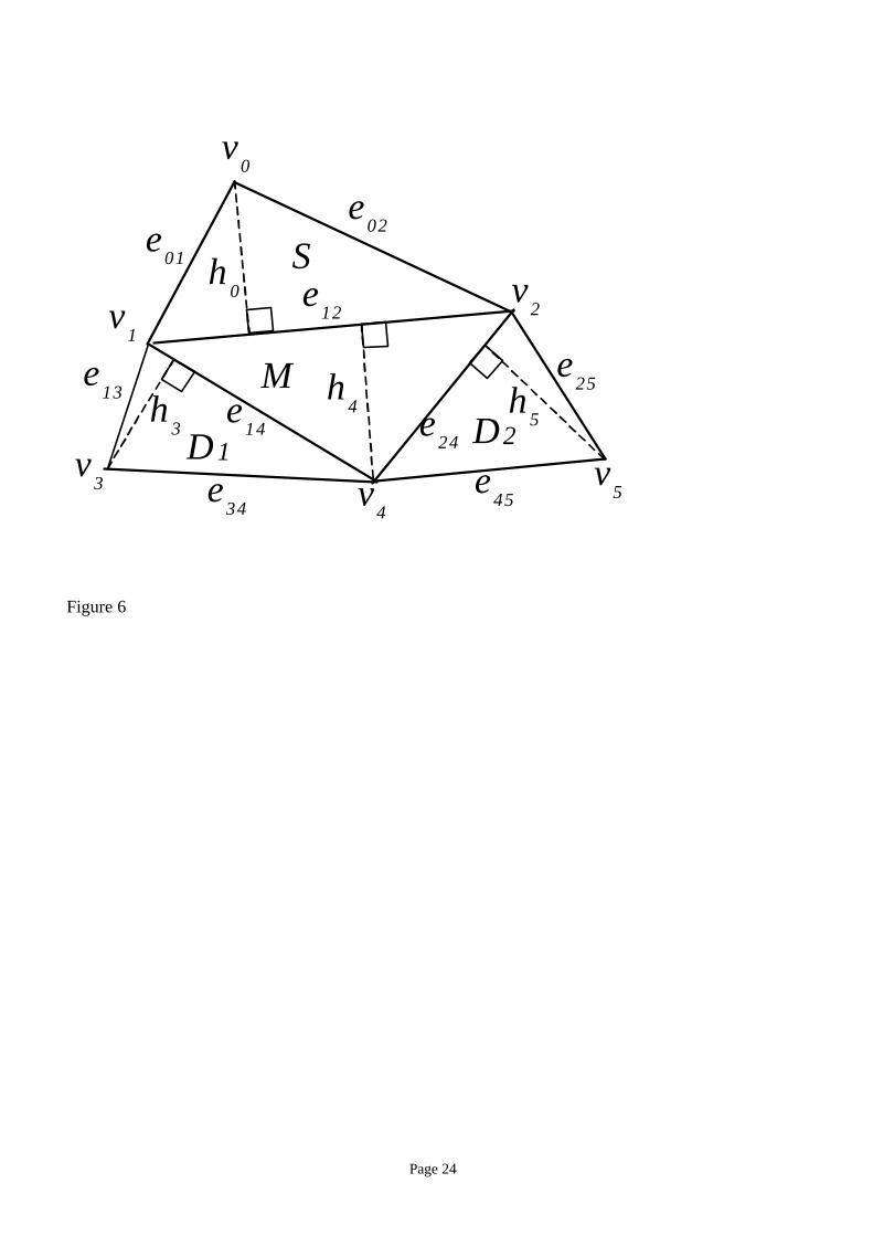
3.1. Triangle similarity quadruple embedding
A pair of dimensionless quantities, such as {b/a, h/c} or {θ1,θ2} in Figure 5, defines a set of similar
triangles. The algorithm described in this section, which is called the Triangle Similarity Quadruple
(TSQ) algorithm, uses such a dimensionless quantity pair as the geometrical embedding primitive to
watermark triangular meshes. To realize subscript ordering, the algorithm uses a quadruple of adjacent
triangles that share edges in the configuration depicted in Figure 6 as a Macro-Embedding-Primitive
(MEP). Each MEP stores a quadruple of values {Marker, Subscript, Data1, Data2}. A marker is a
special value (in this case a pair of values) that identifies MEPs. In Figure 6, the triangle marked M
stores a Marker, S stores a Subscript, and D1 and D2 store data values Data1 and Data2. While each MEP
is formed by topology, a set of MEPs are arranged by the quantity of subscript.
The TSQ extraction algorithm does not require an escrowed original cover-3D-model for extraction.
However, it does require a pair of values that identifies marker triangles. Watermarks produced by the
TSQ algorithm withstand translation, rotation, and uniform-scaling transformations of the stego-3D-
models. The watermarks are resistant to resection and local deformation, since subscript arrangement
and repeated embedding are employed. The watermarks can be destroyed by randomization of
coordinates, by a more general class of geometrical transformation, or by extensive topological
alteration such as re-meshing, among other disturbances.
The TSQ algorithm embeds a message according to the following steps.
(1) Traverse the input triangular mesh to find a set of four triangles to be used as an MEP. In doing so,
avoid vertices that have already been used for the watermark, or triangles that are unfit for stable

Page 9
embedding, such as triangles whose dimension-less quantities are too small.
(2) Embed the marker value in the center triangle of the MEP by changing its dimensionless quantity
pair {e14/e24, h4/e12}, and thus the coordinates of its vertices v1, v2, and v4, by small amounts (see
Figure 6).
(3) Embed a subscript and two data symbols in the remaining three triangles of the MEP by displacing
vertices v0, v3, and v5, which are not shared with the marker triangle in the center. Subscript is
embedded in the pair {e02/e01, h0/e12}, and two data symbols are embedded in the pairs {e13/e34, h3/e14}
and {e45/e25, h5/e24}. For each of the three triangles, the algorithm first modifies the ratio hi/eij by
changing only hI , and then modifies the ratio eij/ekl while keeping the height hi constant.
(4) Repeat (1) to (3) above until all the data symbols of the message are embedded.
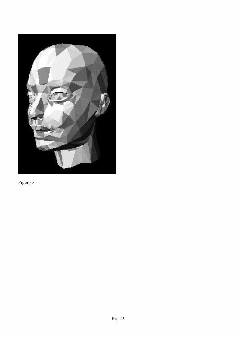
To embed multiple copies of the message, steps (1) to (4) are repeated many times. Figure 7 shows
triangles that formed MEPs in darker gray. Owing to the mutual exclusion rule described in step (1)
above, MEPs do not share vertices.
In steps (2) and (3) above, the magnitude of modification of the quantities must be larger than the
expected noise. At the same time, it must be small enough for the watermarks to be unnoiticeable by
human beings when displayed by using a model browser. These minimum and maximum magnitudes of
modifications are chosen as a result of a trade-off between robustness, space efficiency, and
noticeability.
Given a watermarked mesh and two numbers that identify marker triangles, extraction proceeds
according to the following steps:
(1) Traverse a given triangular mesh and find a triangle with the marker, thereby locating a MEP.
(2) Extract a subscript and two data symbols from the triangles in the MEP.
(3) Repeat (1) to (2) above for all the marker triangles on a given triangular mesh.
(4) Sort the extracted symbols according to their subscripts.
The TSQ algorithm performs a simple error correction by majority voting if multiple copies of a
message are embedded.
Figure 8a shows a model of Beethoven’s bust (4889 triangles, 2655 vertices) in which six identical
copies of a message, each message consisting of 132 bytes, have been embedded by using the TSQ
algorithm. The message was gradually lost when the model was resected by arbitrary planes (Figure 8b-
c). As shown in Table 1, cutting the model in half left the entire message intact, and quartering the
model left 102 out of 132 bytes intact. Since a subscript arrangement was used, intact characters still

Page 10
tended to be in the correct positions within the message string.
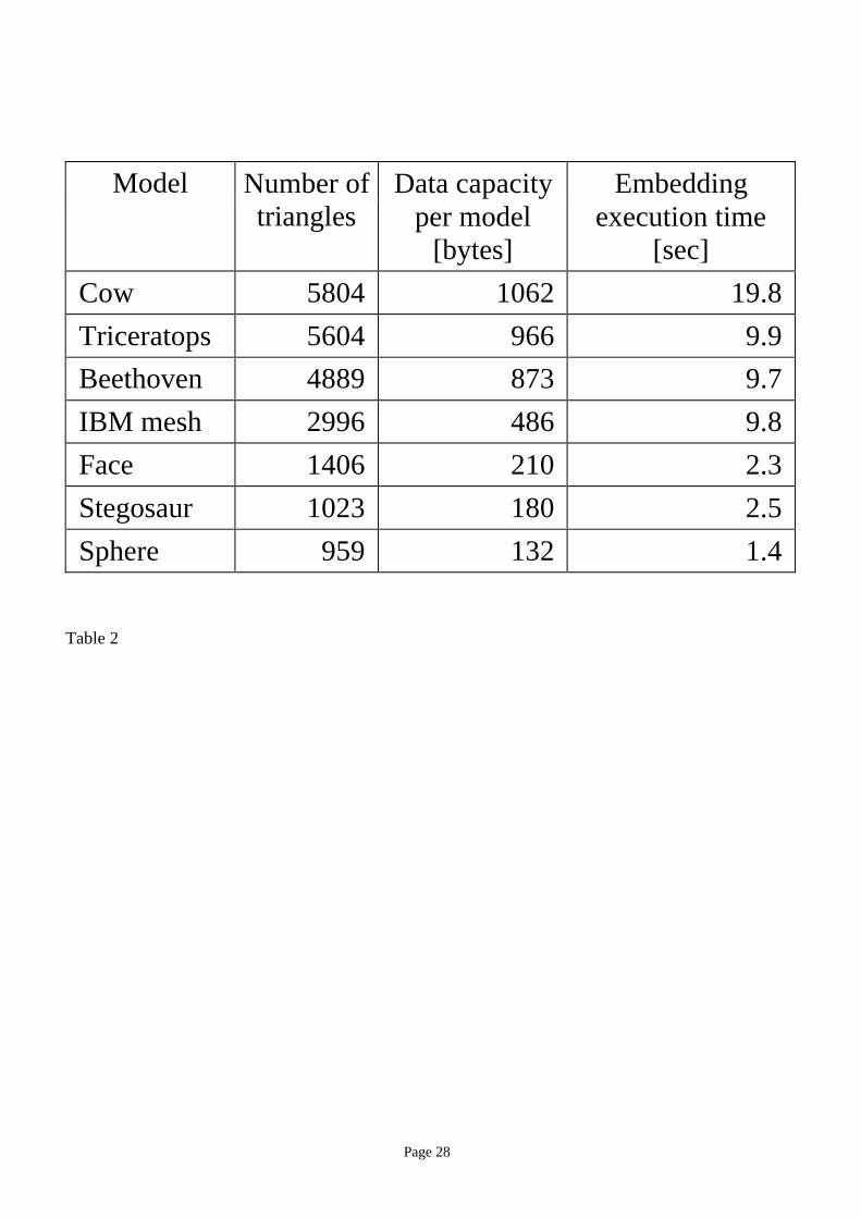
Table 2 shows, for various models, their data capacities and execution times for embedding in the
case of the TSQ algorithm. Times for extraction were not listed since they are about the same as those
for embedding. The times were measured by using IBM AIXTM 4.1.4 operating system and a xlC c++
compiler on a 100 MHz PowerPC 604 processor.
The space efficiency in these examples is adequate for many practical applications. It should be
noted, however, that these examples pushed space efficiency by sacrificing robustness to some extent.
Increasing robustness, for example by increasing the number of repetitions of a message and using an
error-correcting code, would reduce the effective data capacity.
Execution times are roughly proportional to the number of triangles in the models. The embedding
algorithm was prototyped on a full-fledged non-manifold modeler kernel, which has many more features
than necessary for the embedding algorithm. The times will improve significantly if the code is
optimized for the embedding algorithm.
3.2. Tetrahedral volume ratio embedding
The ratio of the volumes of a pair of tetrahedrons is the embedding primitive for the Tetrahedral
Volume Ratio (TVR) embedding algorithm described in this section. The algorithm is designed to accept
triangular meshes as its input. It arranges the embedding primitives topologically into either a global or a
local one-dimensional arrangement for symbol sequence embedding.
The TVR algorithm does not require a cover-3D-model for extraction. The watermarks that it
produce survive affine transformation, but are destroyed by topological modifications such as re-
meshing, randomization of vertex coordinates, and geometrical transformations more general than affine
transformation (e.g., projection transformation), among other disturbances. A variation of the TVR
algorithm discussed at the end of this section is resistant to resection and local deformation through the
use of local arrangement and repeated embedding.
The TVR algorithm embeds data in accordance with the following steps. The crux of the algorithm
is the establishment of a global one-dimensional arrangement of embedding primitives. Details of step
(1) below will be explained later.
(1) Find a spanning tree of vertices Vt, called a vertex tree [Taubin96], on the input triangular mesh M,
given an initial condition Ivt for Vt. Convert Vt into a sequence of triangles Tris, called a triangle
sequence.
(2) Convert Tris into a sequence of tetrahedrons Tets, called a tetrahedron sequence. To do this,

Page 11
compute a common apex as the centroid of the coordinates of a few triangles selected from the
triangle sequence (e.g., the first three). The selected triangles are removed from the triangle sequence
so that their coordinates are not modified by embedding of symbols.
(3) Convert Tets into a sequence of ratios of volumes Vrs. To do this, select the volume of a tetrahedron
(e.g., the first one) in Tets as a common denominator of all the ratios, and use the volumes of the
remaining tetrahedrons for numerators.
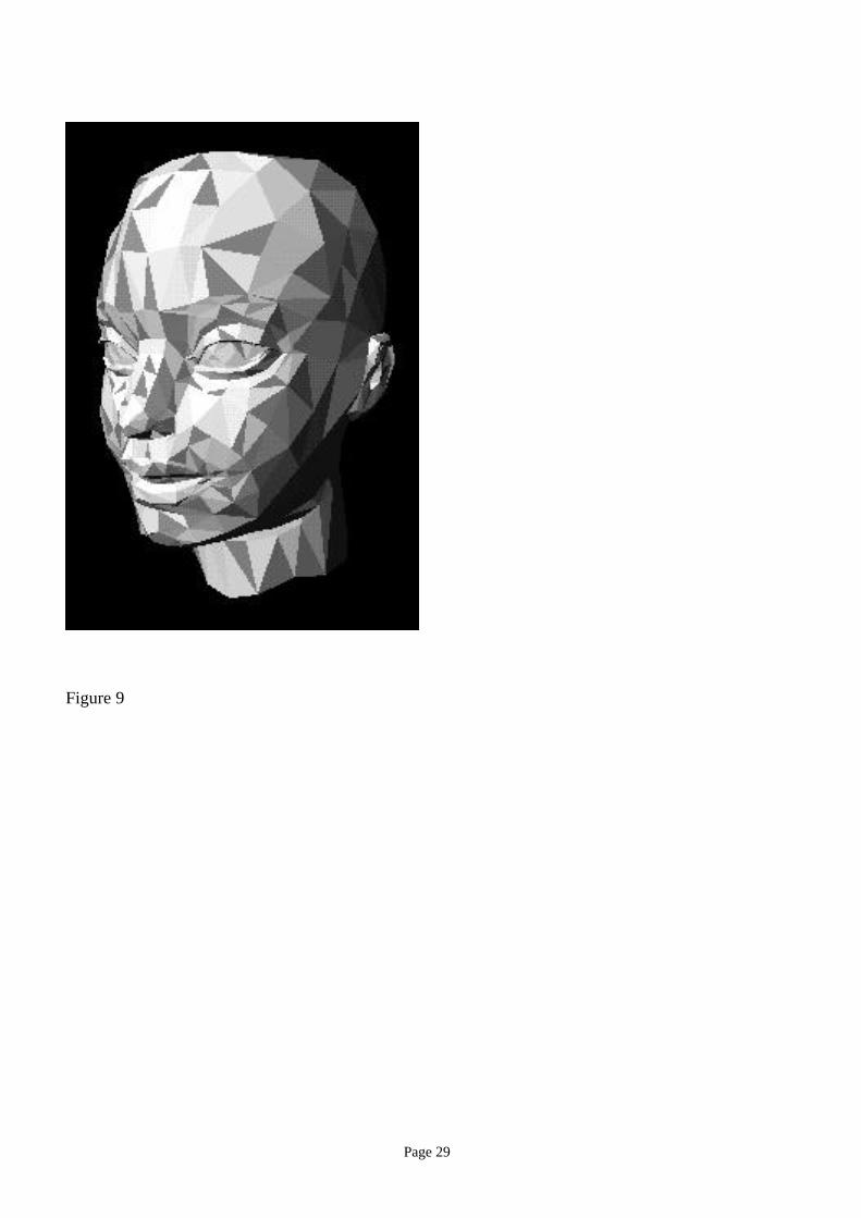
(4) Embed a symbol into each ratio by displacing the vertices of the numerator-tetrahedrons. The vertex
displacements for the current symbol must not interfere with modifications of the previously
embedded symbols. (In Figure 9, triangles that are used for embedding, which are colored dark gray,
do not share edges because of this constraint.)
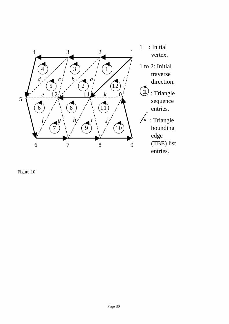
We now explain details of the first step, starting with the method for creating a triangle sequence,
and later come back to explain how to find an initial condition Ivt.
Generating a vertex tree Vt from an input triangular mesh requires that the input mesh be an
orientable manifold. To generate Vt, traverse vertices from a given initial condition Ivt, that is, {initial
vertex, initial traverse direction} pair, starting with Vt initialized to empty. At each vertex, by scanning
the edges in counter-clockwise order, find an edge that is not a member of Vt and does not loop back to
any of the vertices covered by Vt. If such an edge is found, add it to Vt.
In the example shown in Figure 10, the vertex tree has a root (and a branching point) at the vertex
numbered 1. After passing through vertices 1 through to 10, the traverse backtracks to vertex 1 and adds
two vertices, 11 and 12.
The vertex tree Vt is converted into the triangle sequence Tris as a set of edges Tbe, called a Triangle
Bounding Edge (TBE) set is constructed. Tbe is initialized to a set of edges that connect vertices in Vt.
To add an edge to Tbe, vertices are traversed according to Vt, starting from the root. At each vertex, all
the edges adjacent to the vertex are scanned clockwise, and the scanned edge is added to Tbe if it is not a
member of Tbe. A new triangle is added to Tris, which started as an empty sequence, if all three edges of
the triangle are in Tbe for the first time and the triangle is not already in Tris. In the example shown in
Figure 10, edges (except the initial entries of Tbe) are marked alphabetically in the order of their
addition to Tbe, using alphabetical ordering. In the figure, members of Tris are marked with the numbers
in circles according to the sequence in which each triangle is added to Tris.
As the initial condition, the TVR algorithm selects an initial edge, instead of {initial vertex, initial
traverse direction} pair mentioned before. To select the initial edge, the algorithm computes, for every
edge in the model, the volume of the tetrahedron subtended by the two triangles adjacent to the edge
Page 12
(Figure 11). The algorithm selects, as the initial edge, the edge for which the tetrahedron’s volume is
largest. The reason why this method works is that affine transformation preserves inequality among
volumes of tetrahedrons. (Note that these tetrahedrons are different set from the ones used to embed
symbols.)
The TVR extraction algorithm employs the trial-and-error method to find a correct initial edge. The
algorithm tries multiple candidate edges until it extracts a correct predetermined lead-in symbol
sequence. This is because the edge found to have the largest volume may be incorrect owing to noise
and other reasons.
Using an edge as initial condition leaves two equally possible alternatives in starting a traversal to
construct a vertex tree. Again, this ambiguity is resolved by using the trial-and-error method. The TVR
extraction algorithm extracts two sequences of symbols by using both alternatives. It then choose the
direction that yields the correct predetermined lead-in symbol sequence.
Table 3 shows, for various models, the data capacity and the execution time for the embedding
operation. The conditions for time measurements are the same as in Table 2. As with the TSQ algorithm,
the amount of data that can be embedded by using the TVR algorithm appears to be adequate for many
applications. The execution times in the same table show a similar tendency to those obtained with the
TSQ algorithm; they are roughly proportional to the size of the model. They also leave room for a
significant improvement through the design of an optimized code.
As mentioned before, the watermarks created by the TVR algorithm can be made resistant to
resection and local deformation by using a local or subscript arrangement method combined with
repeated embedding. The TVR algorithm strengthened by a local arrangement method called TVR
Cluster (TVRC) embedding algorithm was used in the examples shown in Figure 12. To create sub-
domains for local arrangement, this algorithm simply split the model into subsets (i.e., multiple
disconnected meshes). Boundaries of subsets have duplicate vertices and edges so that cracks will not
become visible. In this example, the message embedded in a model of a cow survived affine
transformations. It also survived, to some extent, resections of a part of the model.
3.3. Mesh density pattern embedding
Another simple pattern-embedding algorithm, named Mesh Density Pattern embedding, generates
polygonal mesh models given curved surface models as inputs. As the algorithm tessellates given curved
surfaces, it embeds a visible pattern by modulating the sizes of triangles in the output mesh (Figure 13a).
This pattern is hardly visible if displayed with a smooth shading (e.g., Gouraud shading) using proper
Page 13
vertex normal vectors calculated from the original curved surfaces, but becomes visible when displayed
by using wire mesh rendering.
This watermark withstands practically every geometrical transformation. The algorithm is resistant
but not immune to polygonal simplification and other topology manipulations. Figure 13b shows an
example of the effects of polygonal simplification in which the number of triangles in the original mesh
has been more than halved by a polygonal simplification algorithm. The pattern will eventually be
destroyed as a result of the simplification. However, a visible watermark may be just enough to deter
unauthorized use of the data.
Note that many topological embedding methods can be combined with geometrical embedding
methods. In fact, the “IBM mesh” model used in the examples of Tables 2 and Table 3 is the mesh
shown in Figure 13a. Combining multiple embedding methods, each with its own strength and weakness,
is a possible approach to increasing the utility of data embedding.
4. Summary and future Work
In this paper, we have introduced the concept of data embedding into 3D polygonal models. After
describing the background and requirements, we argued that geometry is the best data type in a 3D
geometrical model for embedding. Among many models of geometry, we chose polygonal model as the
target of embedding for the study reported in this paper. We presented fundamental methods for
embedding data into a polygonal model, namely, geometrical and topological embedding primitives and
methods for introducing order into a set of modification primitives. Finally, we presented several simple
data-embedding algorithms along with examples of their execution.
The algorithms described in this paper are merely examples of how to provide information channels
in a 3D polygonal model. Some of them may be useful for inventory or for notifying cooperative users
of the existence of copyright. However, they are not robust enough, for example, to prove that a theft has
occurred. They lack many qualities, the most important of which is robustness, that are considered
necessary for most applications of data embedding.
Development of more robust data embedding algorithms will be a focus of our future effort. Data
embedding for 3D models whose intended purpose is not simple viewing is an interesting arena to
explore. For example, Computer Aided Design models that are used for manufacturing may not tolerate
vertex displacement. We also would like to widen the class of target objects for watermarking, for
example, to include parameters defining curved surfaces and vertex normal vectors.

Page 14
Acknowledgements
The authors would like to thank Mei Kobayashi and Shuichi Shimizu for helpful discussions. The
authors also would like to thank anonymous reviewers for valuable comments.
References
[Braudway96] G. Braudway, K. Magerlein, and F. Mintzer, Protecting Publicly-Available Images with a
Visible Image Watermark, IBM Research Report, TC-20336 (89918), January 15, 1996.
[Cox95] I. J. Cox, J. Kilian, T. Leighton, and T. Shamoon, Secure Spread Spectrum Watermarking for
Multimedia, Technical Report 95-10, NEC Research Institute, 1995.
[Farin96] G. Farin, Curves and Surfaces for CAGD: a Practical guide, Fourth edition, Academic Press,
1996.
[Hartung97] F. Hartung, B. Girod, Copyright Protection in Video Delivery Networks by Watermarking
of Pre-Compressed Video, Lecture Notes in Computer Science, Vol. 1242, pp.423-436, Springer, 1997.
[ISO96] ISO/IEC JTC1 SC24/N1596 CD #14772 Virtual Reality Model Language (VRML 2.0)
[Masuda96] H. Masuda, Topological operations for non-manifold geometric modeling and their
applications, Ph. D dissertation, Department of Precision Machinery Engineering, University of Tokyo,
1996 (in Japanese).
[O’Rourke94] J. O’Rourke, Computational Geometry in C, Cambridge University Press, 1994.
[O’Ruanaidh96] J. J. K. O’Ruanaidh, W. J. Dowling, F. M. Boland, Watermarking Digital Images for
Copyright Protection, IEE Proc.-Vis. Image Signal Process., Vol. 143, No. 4, pp. 250-256, August 1996.
[Pfitzmann96] B. Pfitzmann, Information Hiding Terminology, in R. Anderson, Ed., Lecture Notes in
Computer Science No. 1174, pp347-350, Springer, 1996.
[Smith96] J. R. Smith and B. O. Comiskey, Modulation and Information Hiding in Images, in R.
Anderson, Ed., Lecture Notes in Computer Science No.1174, pp. 207-296, Springer, 1996.
[Tanaka90] K. Tanaka, Y. Nakamura, and K. Matsui, Embedding Secret Information into a Dithered
Multilevel Image, Proc. 1990 IEEE Military Communications Conference, pp. 216-220, 1990.
[Taubin96] G. Taubin, Geometric Compression Through Topological Surgery, IBM Research Report,
RC-20340 (89924), January 16, 1996.
Page 15
[Walton95] S. Walton, Image Authentication for a Slippery New Age, Dr. Dobb’s Journal, pp. 18-26,
April 1995.
[Weiler86] K. Weiler, The Radial Edge Structure: A Topological Representation for Non-Manifold
Geometric Boundary Modeling, Geometric Modeling for CAD Applications, North Holland, pp. 3-36,
May 1986.
[Zhao96] J. Zhao and E. Koch, Embedding Robust Labels into Images for Copyright Protection, Proc. of
the Int’l. Congress on Intellectual Property Rights for Specialized Information, Knowledge, and New
Technologies, Vienna, August 1995.

Page 16
List of figure and table captions
Figure 1. Three-dimensional models of dinosaurs in this simple scene are embedded with copyright
notices and contact addresses, which canbe extracted and displayed on demand.
Figure 2. Data embedding into 3D polygonal models.
Figure 3. Simple examples of topological embedding primitives.
Figure 4. Illustrations of examples of global, local, and subscript arrangements defined on a geometrical
object.
Figure 5. Examples of dimension-less quantities that define a set of similar triangles.
Figure 6. A macro-embedding-primitive. In the figure, vi are vertices, eij are lengths of the edges, and hi
are heights of the triangles.
Figure 7. A model watermarked by using the TSQ algorithm. Macro embedding primitives, each of
which consists of four adjacent triangles, are shown in dark gray.
Figure 8. A model of a Beethoven’s bust (4889 triangles) resected repeatedly by arbitrary planes.
Table 1. Data loss due to resection in the example shown in Figure 8.
Table 2. Model size, embedding data capacity, and execution time for embedding operation for the TSQ
algorithm.
Figure 9 Triangles used for embedding by the TVR algorithm are shown in dark gray.
Figure 10. An example showing a vertex tree, a triangle bounding edge list, and a triangle sequence.

Page 17
Figure 11. The volume of the tetrahedron a-b-c-d, subtended by two triangles a-d-c and b-c-d that are
adjacent to the edge c-d, is computed. The arrows show two possible initial traverse orders from the
edge c-d
Table 3. Model size, data capacity, and execution time for embedding operation for the TVR algorithm.
Figure 12. (a) Three-dimensional model of a cow (5804 triangles). (b) A message is embedded by using
the TVR algorithm enhanced with local arrangement and repeated embedding.. The message survives (c)
affine transformation or (d) resection.
Figure 13. Pattern embedding and effect of a mesh simplification algorithm on the embedded pattern.
(a) Pattern is embedded by modulating mesh size by a factor of 1/4 (2996 triangles). (b) The mesh after
polygonal simplification (1374 triangles).
Page 18
Biographies
Dr. Ryutarou Ohbuchi received a BS degree in Electrical and Electronic Engineering from the Sophia
University in Tokyo, Japan in 1981, an MS degree in computer science from the University of Electro-
Commnications in Tokyo, Japan in 1983, and a Ph.D. degree in computer science from the University of
North Carolina at Chapel Hill, USA, in 1994. He is currently a researcher at IBM Research, Tokyo
Research Laboratory, Japan. His research interests include computer graphics, especially augmented
reality, and its application to medicine.
Dr. Hiroshi Masuda received a BS degree in 1985, an MS degree in 1987, and a Ph.D. degree in 1996,
in precision machinery engineering, all from the University of Tokyo. He is currently a research staff at
IBM Research, Tokyo Research Laboratory, Japan. His research interest includes geometric modeling,
computer graphics, and their applications to engineering problems.
Dr. Masaki Aono received a BS degree and an MS degree in information science, both from the
University of Tokyo, Japan, in 1981 and 1984, respectively, and a Ph.D. degree in computer science
from Renseelaer Polytechnic Institute, USA, in 1994. He is currently a project manager of Advanced
Graphics & CAD group in IBM Research, Tokyo Research Laboratory. His research interests include
computer graphics and computer-aided geometric design.
Page 19
figure 1
Page 20
Embedding(and meshing)
Cover-3D-model
Stego-3D-model
Embeddeddata
Polygonalmesh
or
Curvedsurface
Polygonalmesh
Stego-3D-model
Extraction
Delivery through media
Embeddeddata
Text,number,pattern,
etc.surface
Figure 2

Page 21
(a) (b)
oror
Figure 3

Page 22
12
12 4
56
7
8
9 10 113 13
(a) Global (b) Local (c) Subscript
Figure 4

Page 23
1θ 2θ
a b
c
h
Figure 5
Page 24
e13
v0
v2v
1
v3 v
4
v5
e01
e02
e12
e14
e34
e24
e25
e45
h3
h0
h5
h4
S
M
D2D1
Figure 6
Page 25
Figure 7

Page 26
Figure 8
(a) (b) (c) (d)

Page 27
Number of
triangles
Data
(a) 4889 6 copies, 132 bytes each
(b) 2443 132/132 bytes
(c) 1192 102/132 bytes
(d) 399 85/132 bytes
Table 1
Page 28
Model Number oftriangles
Data capacityper model
[bytes]
Embeddingexecution time
[sec]
Cow 5804 1062 19.8
Triceratops 5604 966 9.9
Beethoven 4889 873 9.7
IBM mesh 2996 486 9.8
Face 1406 210 2.3
Stegosaur 1023 180 2.5
Sphere 959 132 1.4
Table 2
Page 29
Figure 9
Page 30
4
4
6
3 2 1
512
7 9
10
8
11
3 1
5 2 12
7 9 10
6 8 11
l
j
k
abcd
e
f g h i
1 : Initialvertex.
1 to 2: Initialtraversedirection.
1 : Trianglesequenceentries.
a : Triangleboundingedge(TBE) listentries.
Figure 10

Page 31
ab
c
d
Figure 11

Page 32
Model Number oftriangles
Data capacityper model
[byte]
Embeddingexecution time
[sec]
Cow 5804 1027 20.2
Triceratops 5604 650 7.2
Beethoven 4889 324 9.6
IBM mesh 2996 652 9.9
Face 1406 116 2.2
Stegosaur 1023 225 2.4
Sphere 959 216 1.5
Table 3

Page 33
Figure 12a

Page 34
Figure 12b

Page 35
Figure 12c

Page 36
Figure 12d

Page 37
Figure 13a

Page 38
Figure 13b