water operation and maintenance bulletinusbr.gov/assetmanagement/waterbulletins/230sept2012.pdf ·...
TRANSCRIPT
U.S. Department of the Interior Bureau of Reclamation September 2012
Water Operation and Maintenance Bulletin No. 230
I n T h i s I s s u e . . .
Types and Maintenance of Pipe Systems Concrete Repair and Maintenance Visual Checklist for Canal Embankment and Repairs
U.S. Department of the Interior Bureau of Reclamation
This Water Operation and Maintenance Bulletin is published quarterly for the benefit of water
supply system operators. Its principal purpose is to serve as a medium to exchange information
for use by Bureau of Reclamation personnel and water user groups in operating and maintaining
project facilities.
The Water Operation and Maintenance Bulletin and subject index may be accessed on the
Internet at: www.usbr.gov/assetmanagement.
Although every attempt is made to ensure high quality and accurate information, the Bureau of
Reclamation cannot warrant nor be responsible for the use or misuse of information that is
furnished in this bulletin.
For further information about the
Water Operation and Maintenance Bulletin, contact:
Kenneth Schwairy, Managing Editor
Bureau of Reclamation
Technical Service Center (86-68360)
PO Box 25007, Denver, CO 80225-0007
Telephone: (303) 445-3015
FAX: (303) 445-6483
Email: [email protected]
Cover photograph: Lack of proper maintenance resulting in near loss
of structure.
Any information contained in this bulletin regarding commercial products may not be
used for advertisement or promotional purposes and is not to be construed as an endorsement of any product or firm by the Bureau of Reclamation.
i
Water Operation and Maintenance Bulletin
No. 230 – September 2012
CONTENTS Page
Types and Maintenance of Pipe Systems.................................................................1
Concrete Repair and Maintenance .........................................................................21
Visual Checklist for Canal Embankment and Repairs ...........................................33
Available on the Internet at:
www.usbr.gov/assetmanagement
1
TYPES AND MAINTENANCE OF PIPE SYSTEMS by: Jim Keith, Program Analyst, Bureau of Reclamation, 84-57000
General
The Bureau of Reclamation (Reclamation) has designed and installed over
3,500 miles of pipe. Although most of this pipe has been for irrigation
distribution systems, we also have worked on large transmission pipelines and
municipal and industrial (M&I) city systems. These pipes have ranged in inside
diameters from 2 inches to 21 feet. The internal pressures have been from zero
pressure (partial flow) to 825 feet of head (358 pounds per square inch [lbs/in2]).
Although most of our pipelines have been buried, we have also worked on
aboveground systems such as penstocks. The buried pipes have had earth covers
that ranged from 3 to 35 feet. With such wide ranges in design requirements and
water district pipe preferences, Reclamation has used the following types of pipe:
asbestos-cement, ductile iron, embedded cylinder prestressed concrete, lined
cylinder prestressed concrete, monolithic cast-in-place, noncylinder prestressed
concrete, polyethylene (PE), polyvinyl chloride (PVC), pretensioned concrete
cylinder, reinforced concrete cylinder, reinforced concrete pressure, fiberglass,
and steel.
Pipeline Systems Terminology
Pipeline – This generic term can be applied to any pipe system. In Reclamation,
this usually refers to a pressurized pipe system that supplies water for irrigation or
municipal purposes. Reclamation normally works on pressurized pipe systems,
except for drainage applications.
Siphons – This type of pipe is usually associated with a canal. Siphons are used
to cross gullies or washes. The use of the term ―siphon‖ is actually a misnomer,
as they are really inverted siphons, meaning that the pipe does not go higher than
the hydraulic head available.
Culverts – This term applies to pipe that is used to pass runoff water under
another structure. These are designed for very low or no pressure. These types of
pipes are usually corrugated PVC or corrugated PE, corrugated metal, or concrete
because of the low cost for these materials.
Laterals – This term is usually associated with water distribution systems.
Canals or pipelines are both commonly called laterals.
Water Operation and Maintenance Bulletin
2
Municipal and Industrial (M&I) – This type of system supplies large volumes
of water from one point to another. Typically, the water is supplied to cities or
other large users. There are normally only a small number of deliveries
associated with an M&I system.
Distribution – This system delivers water to a large number of locations.
Distribution systems have smaller flow rates than what are used in M&I systems.
These systems generally supply water to farm units on Reclamation projects and
homes in city systems.
Gravity – Water flows through this type of pipeline system by static pressure.
The static pressure can be supplied by a tank, regulating reservoir, or canal water
surface, which are generally located at a high point. The delivery water surface
elevations at delivery points are below the source water surface elevation.
Pumped – The pressure in this type of system is supplied by pumps at the
beginning of the pipeline or anywhere in the system. In pumped systems, the
delivery water surface elevations at delivery points may be above the pump sump
water surface elevation.
Pipe Terminology
These are common terms associated with pipes:
Pipe – Pipe is defined as a seamless tube conforming to the particular dimensions
commonly known as standard pipe size (from American Society for Testing and
Materials [ASTM] B-251-557).
Springline – The springlines are the sides of the pipe at the horizontal centerline
or diameter of the pipe.
Invert – The invert is the bottom inside of the pipe.
Centerline of Pipe – The centerline is the vertical center of the pipe in plan or the
horizontal center in profile.
Crown – The crown is the inside top of the pipe.
Haunch Area – The haunches of the pipe are the outside areas between the
springlines and bottom of the pipe.
Water Operation and Maintenance Bulletin
3
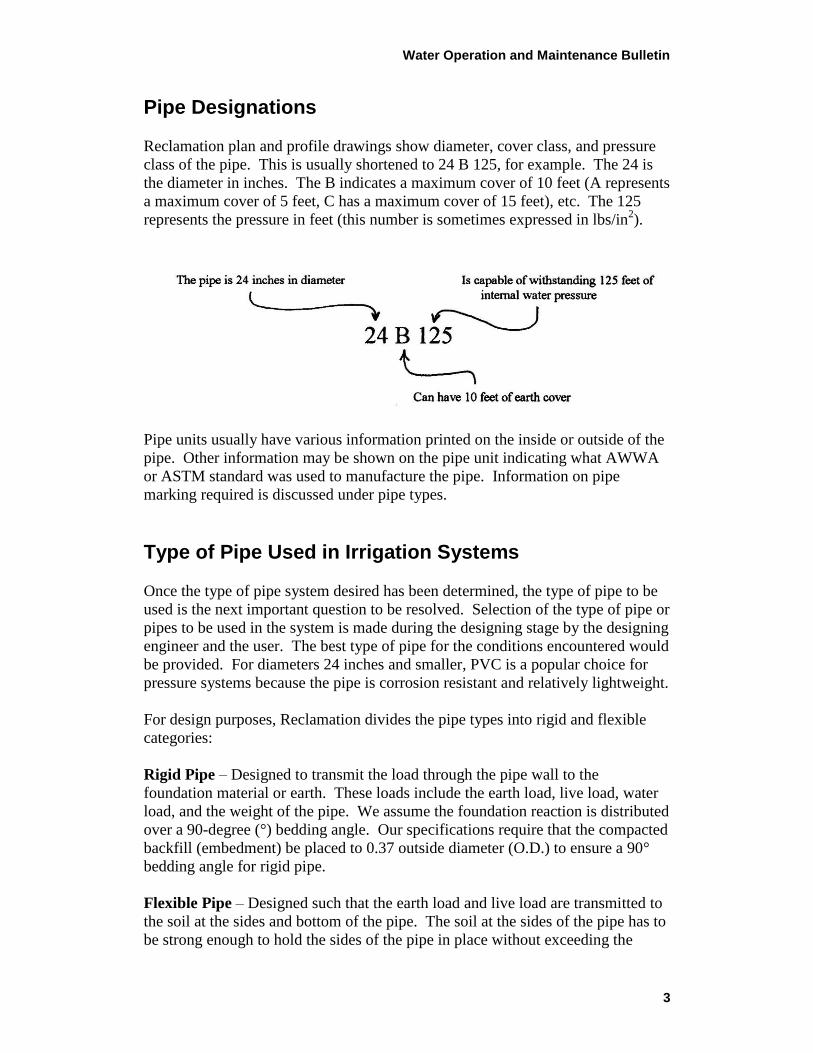
Pipe Designations
Reclamation plan and profile drawings show diameter, cover class, and pressure
class of the pipe. This is usually shortened to 24 B 125, for example. The 24 is
the diameter in inches. The B indicates a maximum cover of 10 feet (A represents
a maximum cover of 5 feet, C has a maximum cover of 15 feet), etc. The 125
represents the pressure in feet (this number is sometimes expressed in lbs/in2).
Pipe units usually have various information printed on the inside or outside of the
pipe. Other information may be shown on the pipe unit indicating what AWWA
or ASTM standard was used to manufacture the pipe. Information on pipe
marking required is discussed under pipe types.
Type of Pipe Used in Irrigation Systems
Once the type of pipe system desired has been determined, the type of pipe to be
used is the next important question to be resolved. Selection of the type of pipe or
pipes to be used in the system is made during the designing stage by the designing
engineer and the user. The best type of pipe for the conditions encountered would
be provided. For diameters 24 inches and smaller, PVC is a popular choice for
pressure systems because the pipe is corrosion resistant and relatively lightweight.
For design purposes, Reclamation divides the pipe types into rigid and flexible
categories:
Rigid Pipe – Designed to transmit the load through the pipe wall to the
foundation material or earth. These loads include the earth load, live load, water
load, and the weight of the pipe. We assume the foundation reaction is distributed
over a 90-degree (°) bedding angle. Our specifications require that the compacted
backfill (embedment) be placed to 0.37 outside diameter (O.D.) to ensure a 90°
bedding angle for rigid pipe.
Flexible Pipe – Designed such that the earth load and live load are transmitted to
the soil at the sides and bottom of the pipe. The soil at the sides of the pipe has to
be strong enough to hold the sides of the pipe in place without exceeding the
Water Operation and Maintenance Bulletin
4
long-term deflections mentioned later. Flexible pipe can withstand these long-
term deflections without damage to the pipe wall. Reclamation specifications
require that the compacted backfill (embedment) be placed to 0.70 O.D. to ensure
that good soil support is achieved at the sides of the flexible pipe.
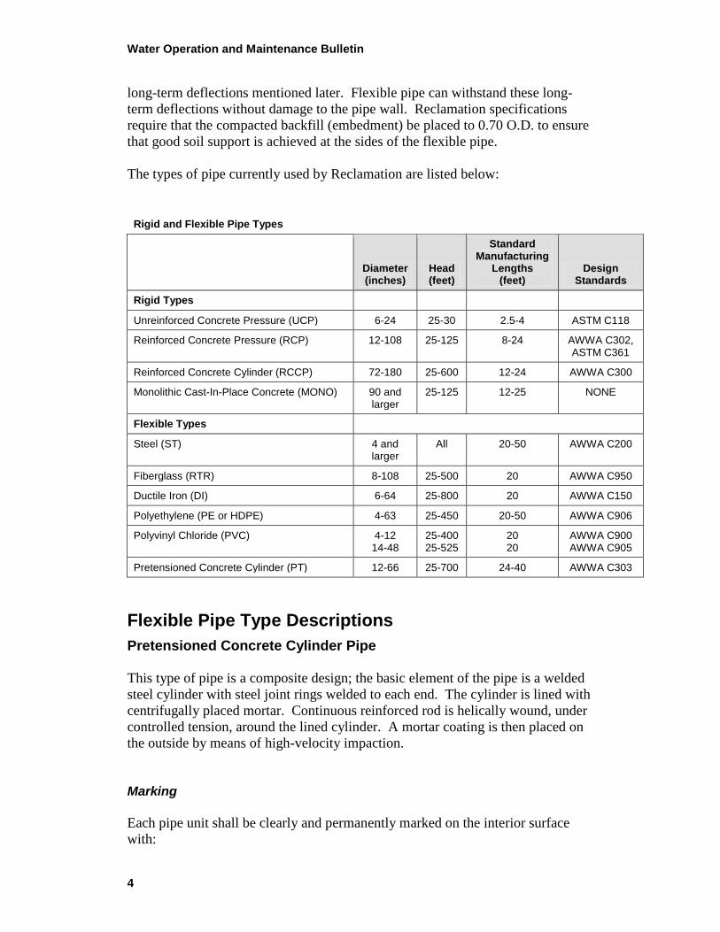
The types of pipe currently used by Reclamation are listed below:
Rigid and Flexible Pipe Types
Diameter (inches)
Head (feet)
Standard Manufacturing
Lengths (feet)
Design Standards
Rigid Types
Unreinforced Concrete Pressure (UCP) 6-24 25-30 2.5-4 ASTM C118
Reinforced Concrete Pressure (RCP) 12-108 25-125 8-24 AWWA C302, ASTM C361
Reinforced Concrete Cylinder (RCCP) 72-180 25-600 12-24 AWWA C300
Monolithic Cast-In-Place Concrete (MONO) 90 and larger
25-125 12-25 NONE
Flexible Types
Steel (ST) 4 and larger
All 20-50 AWWA C200
Fiberglass (RTR) 8-108 25-500 20 AWWA C950
Ductile Iron (DI) 6-64 25-800 20 AWWA C150
Polyethylene (PE or HDPE) 4-63 25-450 20-50 AWWA C906
Polyvinyl Chloride (PVC) 4-12 14-48
25-400 25-525
20 20
AWWA C900 AWWA C905
Pretensioned Concrete Cylinder (PT) 12-66 25-700 24-40 AWWA C303
Flexible Pipe Type Descriptions
Pretensioned Concrete Cylinder Pipe
This type of pipe is a composite design; the basic element of the pipe is a welded
steel cylinder with steel joint rings welded to each end. The cylinder is lined with
centrifugally placed mortar. Continuous reinforced rod is helically wound, under
controlled tension, around the lined cylinder. A mortar coating is then placed on
the outside by means of high-velocity impaction.
Marking
Each pipe unit shall be clearly and permanently marked on the interior surface
with:
Water Operation and Maintenance Bulletin
5
(1) Nominal size and class (e.g., 36 B 225)
(2) Name or trademark of manufacturer
(3) Date of manufacture and number in sequence of production
(4) Type of cement and class of pozzolan (if used)
Polyvinyl Chloride Pipe
PVC plastic resin can be repeatedly softened to a plastic state by the application
of heat and hardened to a solid state by cooling. This type of pipe is
manufactured by extruding the heated, molten plastic through a forming die
to obtain the cylindrical shape of the proper diameter and wall thickness. The
pipe is then immediately cooled and cut to the proper length.
Marking
Each pipe unit shall be clearly and permanently marked on the interior surface
with:
(1) The nominal size and O.D. base (e.g., 24CI)
(2) AWWA C900 or C905
(3) Standard Dimension Ratio (SDR) or Dimension Ratio (DR) (e.g., SDR41
or DR18)
(4) Date of manufacture and shift designation
(5) Name or trademark of manufacturer
Steel Pipe
Steel pipe can be manufactured in practically any size or pressure rating. The
pipe is manufactured by rolling sheet steel (either flat plate or continuous roll)
into a cylindrical shape and welding the edges of the sheet together. The inside of
the pipe is either mortar lined or painted with coal-tar epoxy. The outside is either
mortar coated or tape wrapped.
Marking
Each pipe unit shall be clearly and permanently marked on the interior surface
with:
Water Operation and Maintenance Bulletin
6
(1) Serial number or other identification
(2) Nominal size and class (e.g., 36 B 225)
(3) Name or trademark of manufacturer
(4) Date of manufacture and number in sequence of production
Ductile Iron Pipe
This type of pipe is manufactured by introducing a charge of molten iron into a
rapidly spinning mold. The centrifugal force due to the spinning process forms
the molten iron into a cylinder of uniform thickness, which is determined by the
volume of the molten charge. After cooling and annealing, a thin cement mortar
lining is applied to the inside of the pipe. The inside and outside are then painted
with asphalt. This type of pipe is installed with a continuous encasement of
polyethylene.
Marking
Each pipe unit shall be clearly and permanently marked on the interior surface
with:
(1) Nominal pipe size, 24 inches
(2) Pressure class, PC 150
(3) AWWA C151
(4) Date of manufacture
(5) Name or trademark of manufacturer
Fiberglass Pipe
This type of pipe is sometimes referred to as Reinforced Thermosetting Resin
(RTR) pipe. The pipe is composed of continuous fiberglass filaments in a
polyester resin matrix. The glass strands are wound on a rotating mandrel in
a helical fashion until the required wall thickness is obtained. The helical
angle, which varies among manufacturers, provides longitudinal as well as
circumferential strength.
Marking
Each pipe unit shall be clearly and permanently marked on the interior surface
with:
(1) Nominal pipe size, 24 inches
(2) Pressure class, PC 150
(3) AWWA C950
Water Operation and Maintenance Bulletin
7
(4) Stiffness class (e.g., PS72)
(5) Date of manufacture and shift designation
(6) Name or trademark of manufacturer
Polyethylene Pipe
This type of pipe is manufactured by extruding heated, molten polyethylene
through a forming die to obtain the cylindrical shape of the proper diameter and
wall thickness. The pipe is then immediately cooled and cut to the proper length.
Joints are made by heating the pipe ends and butt fusing the two pieces together.
Marking
Each pipe unit shall be clearly and permanently marked on the interior surface
with:
(1) Nominal size and O.D. base (e.g., 24IPS)
(2) PE material (e.g., PE 3408)
(3) Pressure class (e.g., PC 150)
(4) Dimension Ratio (e.g., DR25)
(5) AWWA C906
(6) Date of manufacture and shift designation
(7) Name or trademark of manufacturer
Rigid Pipe Descriptions
Unreinforced Concrete Pipe
This type of pipe is used for irrigation and drainage applications with low
pressures, under 25 feet of head. The pipe consists of a unreinforced concrete
shell with concrete joints.
Marking
Each pipe unit shall be clearly and permanently marked on the interior surface
with:
(1) Nominal size and class, O.D. 24B25
(2) Name or trademark of manufacturer
(3) Date of manufacture and number in sequence of production
(4) Type of cement and class of pozzolan (if used)
Water Operation and Maintenance Bulletin
8
Reinforced Concrete Pressure Pipe
This type of pipe is commonly called bar pipe or precast pipe and consists of
reinforcement cages placed in a concrete shell to resist bursting pressures and
external earth loads. The joints may be either steel or concrete. Generally,
this pipe type is used where the headclass requirements are 125 feet or less.
Marking
Each pipe unit shall be clearly and permanently marked on the interior surface
with:
(1) Nominal size and class, O.D. 36B125
(2) Name or trademark of manufacturer
(3) Date of manufacture and number in sequence of production
(4) Type of cement and class of pozzolan (if used)
Reinforced Concrete Cylinder Pipe
This type of pipe was developed to handle higher internal heads than reinforced
concrete pressure pipe. This pipe consists of a steel cylinder with steel joint rings
attached and around which a cage of reinforcing steel is placed. The cylinder and
cage assembly comprises the inner layer of reinforcement, a second or outer
reinforcement cage is provided, and concrete is cast around the reinforcement
layers to form the pipe wall. Generally, this pipe type is used where the headclass
requirements are greater than 125 feet.
Marking
Each pipe unit shall be clearly and permanently marked on the interior surface
with:
(1) Nominal size and class, O.D. 72B225
(2) Name or trademark of manufacturer
(3) Date of manufacture and number in sequence of production
(4) Type of cement and class of pozzolan (if used)
Monolithic Cast In-Place Concrete Pipe
This type of pipe, which is constructed in place like a reinforced concrete
structure such as a bridge or building, is similar to reinforced concrete pipe and
generally is used for larger diameter pipe.
Water Operation and Maintenance Bulletin
9
Pipe Joints
Reclamation has found by experience that the pipe joint is one of the most
important features in a pipe system. A good pipe joint must be flexible enough to
permit longitudinal movement due to temperature changes in the water and to
wetting and drying of the pipe, as well as vertical adjustments due to settlement
that sometimes occurs due to the application of irrigation water to adjacent lands.
Low-head pipe (UCP) used on early Reclamation pipe distribution systems
utilized tongue-and-groove precast concrete pipe with a mortar-banded, rigid-type
joint. Pipelines laid with this joint had a low first cost and, generally, a higher
maintenance cost, as well as increased water loss through the life of a project.
This type of joint is now only used occasionally by Reclamation.
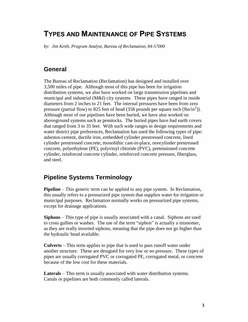
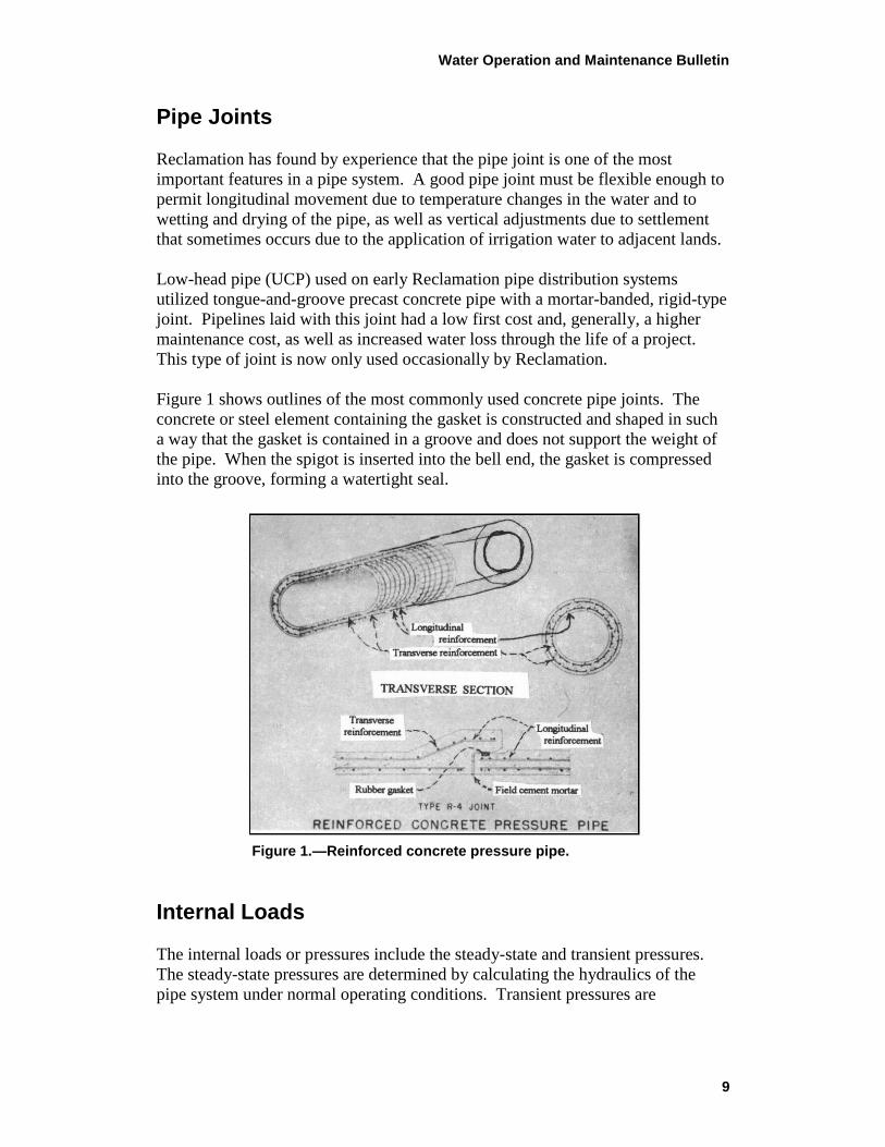
Figure 1 shows outlines of the most commonly used concrete pipe joints. The
concrete or steel element containing the gasket is constructed and shaped in such
a way that the gasket is contained in a groove and does not support the weight of
the pipe. When the spigot is inserted into the bell end, the gasket is compressed
into the groove, forming a watertight seal.
Figure 1.—Reinforced concrete pressure pipe.
Internal Loads
The internal loads or pressures include the steady-state and transient pressures.
The steady-state pressures are determined by calculating the hydraulics of the
pipe system under normal operating conditions. Transient pressures are
Water Operation and Maintenance Bulletin
10
determined by examining abnormal conditions such as power failure and some
normal conditions such as valves opening and closing and pumps stopping and
starting.
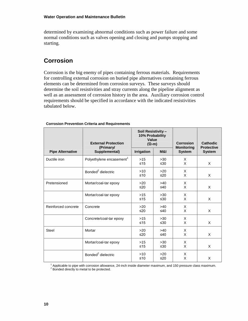
Corrosion
Corrosion is the big enemy of pipes containing ferrous materials. Requirements
for controlling external corrosion on buried pipe alternatives containing ferrous
elements can be determined from corrosion surveys. These surveys should
determine the soil resistivities and stray currents along the pipeline alignment as
well as an assessment of corrosion history in the area. Auxiliary corrosion control
requirements should be specified in accordance with the indicated resistivities
tabulated below.
Corrosion Prevention Criteria and Requirements
Pipe Alternative
External Protection (Primary/
Supplemental)
Soil Resistivity – 10% Probability
Value (Ώ-m) Corrosion
Monitoring System
Cathodic Protective
System Irrigation M&I
Ductile iron Polyethylene encasement1 >15
≤15 >30 ≤30
X X
X
Bonded2 dielectric >10
≤10 >20 ≤20
X X
X
Pretensioned Mortar/coal-tar epoxy >20 ≤20
>40 ≤40
X X
X
Mortar/coal-tar epoxy >15 ≤15
>30 ≤30
X X
X
Reinforced concrete Concrete >20 ≤20
>40 ≤40
X X
X
Concrete/coal-tar epoxy >15 ≤15
>30 ≤30
X X
X
Steel Mortar >20 ≤20
>40 ≤40
X X
X
Mortar/coal-tar epoxy >15 ≤15
>30 ≤30
X X
X
Bonded2 dielectric >10
≤10 >20 ≤20
X X
X
1 Applicable to pipe with corrosion allowance, 24-inch inside diameter maximum, and 150 pressure class maximum.
2 Bonded directly to metal to be protected.
Water Operation and Maintenance Bulletin
11
Appurtenant Structures
Air Valves
Air valves are used in pipeline systems to remove any air that may get trapped
inside the pipeline and, more importantly, for filling and draining the pipeline.
Generally, air valves are placed at high points along the pipe profile. Reclamation
uses a combination air and vacuum valve in most cases to allow air into the
pipeline during draining and to expel air during filling. The size of air valve
controls the amount of time required to fill and drain a pipeline system.
Blowoffs
Blowoffs are required on pipelines to allow water to be emptied for operation and
maintenance requirements, inspection, or repair. Depending on the pressure head
on the blowoff valve, orifice plates or some type of energy dissipater may be
required to prevent damage to the ground where the water exits.
Drains
Drains are similar to blowoffs, but are mainly used on irrigation systems for
small-diameter pipes (less than 27 inches). The water is often emptied into a
gravel pocket buried below ground when draining the pipe to daylight would be
cost prohibitive.
Manholes
Manholes are provided in pipelines 27 inches in diameter and greater. The
manholes provide access as well as ventilation into the pipeline for inspection or
repair. Typical spacing of manholes is every ½ mile for irrigation systems and
every 1,000 feet for M&I and city systems. Manholes should be sized as large as
possible for large-diameter pipes when ladders would be required for access.
Surge Relief
Transients or water hammer waves occur in pipelines when the flow velocity
changes. Generally, these changes are due to valve or pump operations. Various
methods are used to combat these transients. Common methods for the control of
transients are surge tanks, valve closure speeds, flywheels, realignment of
proposed pipe profiles, or air chambers. Gravity system transients can usually be
controlled by slowing the valve closure times. Hydraulic transient analysis
typically includes upsurge and downsurge considerations.
Water Operation and Maintenance Bulletin
12
In pump systems, one method to reduce downsurge problems is to place a
surge tank of equal diameter as the pipeline to dissipate the energy in the
standpipe. The disadvantage of this system is that the surge stand may need to
be several hundred feet tall for high-pressure systems.
Air chambers are also used for the control of transients. An air chamber consists
of a pressure vessel that is partially filled with water and compressed air. The
water is supplied to the pipeline during a downsurge, and the compressed air acts
as a cushion when an upsurge occurs.
Quick opening valves are sometimes used to relieve upsurge pressure on smaller
lines or turnouts. A typical example of this type is a Grove valve, which uses a
rubber bladder held in place by compressed nitrogen until a surge opens the valve.
The bladder closes after the surge has passed, and the amount of water spilled is
generally small.
Delivery Structures
In distribution systems, turnouts are used to deliver water from the main line to
individual users. A delivery structure is usually constructed to provide pressure
reduction, flow measurement and rate of flow control, or isolation. These are
accomplished by using a pressure reducing valve, a flowmeter, an orifice plate
that limits the amount of water that can be taken through the delivery, and a
butterfly valve.
Thrust Restraint
When a pipeline makes a bend, tapers from one pipe diameter to another, or dead
ends, some form of restraint is required to keep a pipe with unrestrained joints
from moving and leaking. This can be accomplished in different ways.
Earth blocking, which consists of compacting an area of soil behind the pipe or
fitting is generally used for small diameters and low-pressure systems. Concrete
blocking or concrete encasement placed around the pipe can prevent movement.
Concrete blocking transfers the thrust on the pipe to an area of concrete that
develops the passive resistance of the adjacent soil. Concrete encasement uses the
weight of the concrete and soil frictional resistance to resist thrust. Combinations
of the two types of concrete thrust restraint have been used. Concrete should
never be placed over flexible joints in high-pressure systems due to the possibility
of leakage at the joint and the high cost of repair.
Concrete collars are used to resist the thrust at tapers or dead ends. Collars are
similar to concrete blocking, except that the concrete encircles the pipe.
Water Operation and Maintenance Bulletin
13
Another method is to tie the pipe joints on either side of the bend with welding,
mechanical joints, or some other restraint. This enables the designer to take
advantage of the earth weight above the pipe in conjunction with the frictional
resistance of the soil to resist the thrust.
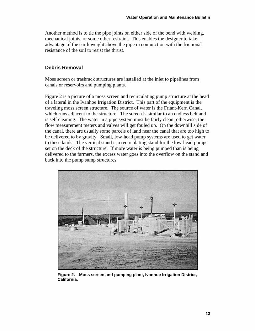
Debris Removal
Moss screen or trashrack structures are installed at the inlet to pipelines from
canals or reservoirs and pumping plants.
Figure 2 is a picture of a moss screen and recirculating pump structure at the head
of a lateral in the Ivanhoe Irrigation District. This part of the equipment is the
traveling moss screen structure. The source of water is the Friant-Kern Canal,
which runs adjacent to the structure. The screen is similar to an endless belt and
is self cleaning. The water in a pipe system must be fairly clean; otherwise, the
flow measurement meters and valves will get fouled up. On the downhill side of
the canal, there are usually some parcels of land near the canal that are too high to
be delivered to by gravity. Small, low-head pump systems are used to get water
to these lands. The vertical stand is a recirculating stand for the low-head pumps
set on the deck of the structure. If more water is being pumped than is being
delivered to the farmers, the excess water goes into the overflow on the stand and
back into the pump sump structures.
Figure 2.—Moss screen and pumping plant, Ivanhoe Irrigation District, California.
Water Operation and Maintenance Bulletin
14
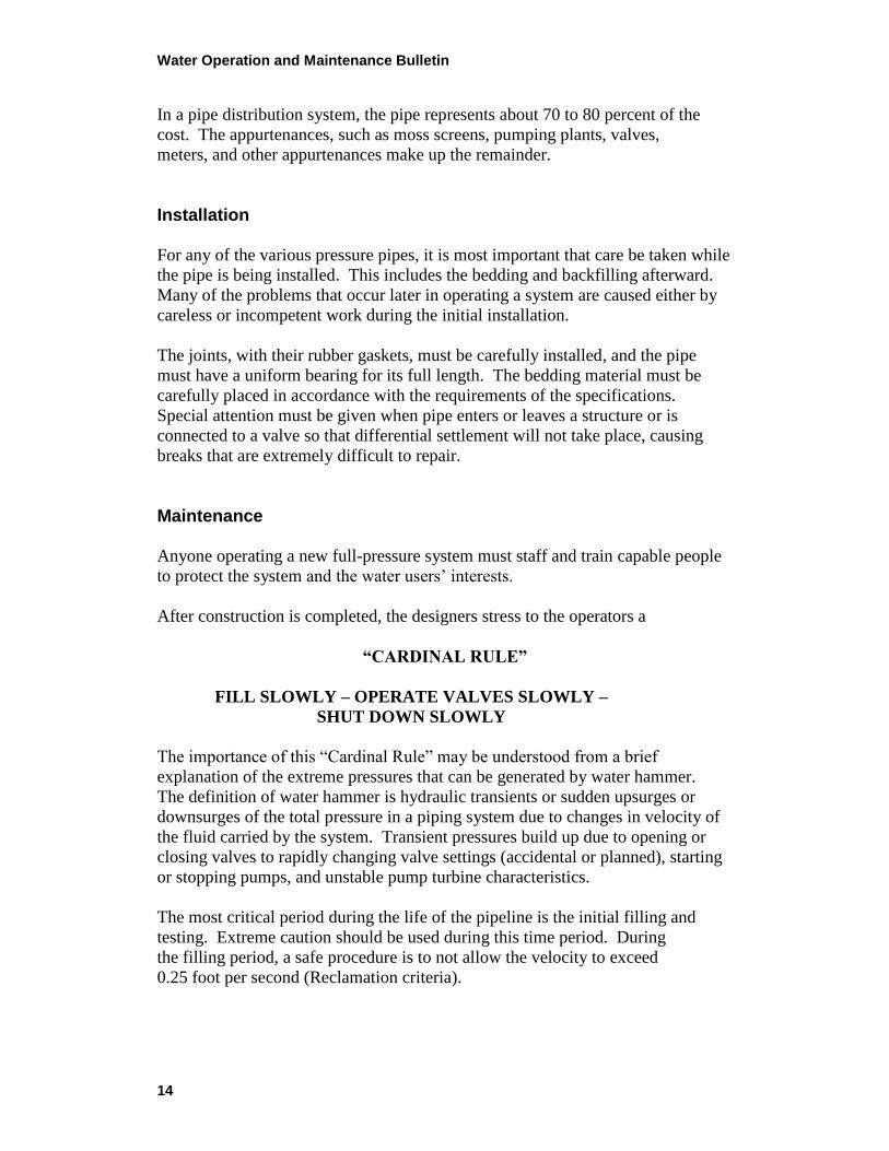
In a pipe distribution system, the pipe represents about 70 to 80 percent of the
cost. The appurtenances, such as moss screens, pumping plants, valves,
meters, and other appurtenances make up the remainder.
Installation
For any of the various pressure pipes, it is most important that care be taken while
the pipe is being installed. This includes the bedding and backfilling afterward.
Many of the problems that occur later in operating a system are caused either by
careless or incompetent work during the initial installation.
The joints, with their rubber gaskets, must be carefully installed, and the pipe
must have a uniform bearing for its full length. The bedding material must be
carefully placed in accordance with the requirements of the specifications.
Special attention must be given when pipe enters or leaves a structure or is
connected to a valve so that differential settlement will not take place, causing
breaks that are extremely difficult to repair.
Maintenance
Anyone operating a new full-pressure system must staff and train capable people
to protect the system and the water users’ interests.
After construction is completed, the designers stress to the operators a
“CARDINAL RULE”
FILL SLOWLY – OPERATE VALVES SLOWLY –
SHUT DOWN SLOWLY
The importance of this ―Cardinal Rule‖ may be understood from a brief
explanation of the extreme pressures that can be generated by water hammer.
The definition of water hammer is hydraulic transients or sudden upsurges or
downsurges of the total pressure in a piping system due to changes in velocity of
the fluid carried by the system. Transient pressures build up due to opening or
closing valves to rapidly changing valve settings (accidental or planned), starting
or stopping pumps, and unstable pump turbine characteristics.
The most critical period during the life of the pipeline is the initial filling and
testing. Extreme caution should be used during this time period. During
the filling period, a safe procedure is to not allow the velocity to exceed
0.25 foot per second (Reclamation criteria).
Water Operation and Maintenance Bulletin
15
Opening and closing valves too rapidly can literally blow pipe out of the ground
and cause extensive damage. The same result can occur if air is trapped in
pipelines by excessively rapid filling and failure to vent all air from the system.
Close observation of air valves during draining and filling and adherence to
Designers’ Operating Criteria in the operation of valves, pumps, and control
facilities is absolutely necessary to prevent damage. Avoiding sudden changes
in velocity will generally avoid serious water hammer surges.
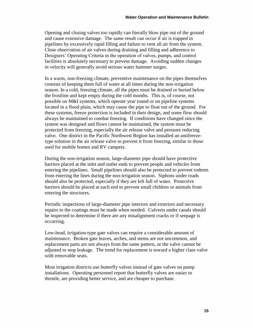
In a warm, non-freezing climate, preventive maintenance on the pipes themselves
consists of keeping them full of water at all times during the non-irrigation
season. In a cold, freezing climate, all the pipes must be drained or buried below
the frostline and kept empty during the cold months. This is, of course, not
possible on M&I systems, which operate year round or on pipeline systems
located in a flood plain, which may cause the pipe to float out of the ground. For
these systems, freeze protection is included in their design, and some flow should
always be maintained to combat freezing. If conditions have changed since the
system was designed and flows cannot be maintained, the system must be
protected from freezing, especially the air release valve and pressure reducing
valve. One district in the Pacific Northwest Region has installed an antifreeze-
type solution in the air release valve to prevent it from freezing, similar to those
used for mobile homes and RV campers.
During the non-irrigation season, large-diameter pipe should have protective
barriers placed at the inlet and outlet ends to prevent people and vehicles from
entering the pipelines. Small pipelines should also be protected to prevent rodents
from entering the lines during the non-irrigation season. Siphons under roads
should also be protected, especially if they are left full of water. Protective
barriers should be placed at each end to prevent small children or animals from
entering the structures.
Periodic inspections of large-diameter pipe interiors and exteriors and necessary
repairs to the coatings must be made when needed. Culverts under canals should
be inspected to determine if there are any misalignment cracks or if seepage is
occurring.
Low-head, irrigation-type gate valves can require a considerable amount of
maintenance. Broken gate leaves, arches, and stems are not uncommon, and
replacement parts are not always from the same pattern, or the valve cannot be
adjusted to stop leakage. The trend for replacement is toward a higher class valve
with removable seats.
Most irrigation districts use butterfly valves instead of gate valves on pump
installations. Operating personnel report that butterfly valves are easier to
throttle, are providing better service, and are cheaper to purchase.
Water Operation and Maintenance Bulletin
16
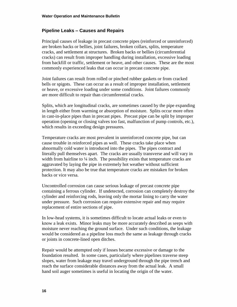
Pipeline Leaks – Causes and Repairs
Principal causes of leakage in precast concrete pipes (reinforced or unreinforced)
are broken backs or bellies, joint failures, broken collars, splits, temperature
cracks, and settlement at structures. Broken backs or bellies (circumferential
cracks) can result from improper handling during installation, excessive loading
from backfill or traffic, settlement or heave, and other causes. These are the most
commonly experienced leaks that can occur in precast concrete pipe.
Joint failures can result from rolled or pinched rubber gaskets or from cracked
bells or spigots. These can occur as a result of improper installation, settlement
or heave, or excessive loading under some conditions. Joint failures commonly
are more difficult to repair than circumferential cracks.
Splits, which are longitudinal cracks, are sometimes caused by the pipe expanding
in length either from warming or absorption of moisture. Splits occur more often
in cast-in-place pipes than in precast pipes. Precast pipe can be split by improper
operation (opening or closing valves too fast, malfunction of pump controls, etc.),
which results in exceeding design pressures.
Temperature cracks are most prevalent in unreinforced concrete pipe, but can
cause trouble in reinforced pipes as well. These cracks take place when
abnormally cold water is introduced into the pipes. The pipes contract and
literally pull themselves apart. The cracks are usually transverse and will vary in
width from hairline to ¼ inch. The possibility exists that temperature cracks are
aggravated by laying the pipe in extremely hot weather without sufficient
protection. It may also be true that temperature cracks are mistaken for broken
backs or vice versa.
Uncontrolled corrosion can cause serious leakage of precast concrete pipe
containing a ferrous cylinder. If undetected, corrosion can completely destroy the
cylinder and reinforcing rods, leaving only the mortar lining to carry the water
under pressure. Such corrosion can require extensive repair and may require
replacement of entire sections of pipe.
In low-head systems, it is sometimes difficult to locate actual leaks or even to
know a leak exists. Minor leaks may be more accurately described as seeps with
moisture never reaching the ground surface. Under such conditions, the leakage
would be considered as a pipeline loss much the same as leakage through cracks
or joints in concrete-lined open ditches.
Repair would be attempted only if losses became excessive or damage to the
foundation resulted. In some cases, particularly where pipelines traverse steep
slopes, water from leakage may travel underground through the pipe trench and
reach the surface considerable distances away from the actual leak. A small
hand soil auger sometimes is useful in locating the origin of the water.
Water Operation and Maintenance Bulletin
17
Among various ways to stop pipeline leaks, the introduction of material into a
pipeline in operation to act as a sealant for small cracks is quick and easy. One
of the earliest sealants used was horse manure. Today, sawdust is sometimes
used. Sawdust, flour, and coarser ground sawdust are mixed with water and
pumped into the line. Naturally, these procedures cannot be used on M&I
systems and, in any case, are only temporary repairs. If the water is removed
from the lines, chances are they will leak again when refilled.
The introduction of anhydrous ammonia (NH3) appears to have a great deal of
promise. The success of the system depends on the precipitation of calcium
carbonate when ammonia is introduced. Unfortunately, the action does not
occur with all waters. Reclamation initiated an investigation of ways and means
of introducing other materials into water along with ammonia to promote
precipitation. A report of this method has been published in Release No. 67
of Reclamation’s Operation and Maintenance Bulletin.
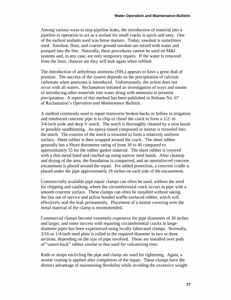
A method commonly used to repair transverse broken backs or bellies in irrigation
and reinforced concrete pipe is to chip or chisel the crack to form a 1/2- to
3/4-inch wide and deep V-notch. The notch is thoroughly cleaned by a wire brush
or possibly sandblasting. An epoxy-based compound or mortar is troweled into
the notch. The exterior of the notch is troweled to form a relatively uniform
surface. Sheet rubber is then wrapped around the crack. The sheet rubber
generally has a Shore durometer rating of from 30 to 40 compared to
approximately 55 for the rubber gasket material. The sheet rubber is covered
with a thin metal band and cinched up using narrow steel bands. After cleanup
and drying of the area, the foundation is compacted, and an unreinforced concrete
encasement is placed around the repair. For added protection, a concrete cradle is
placed under the pipe approximately 18 inches on each side of the encasement.
Commercially available pipe repair clamps can often be used, without the need
for chipping and caulking, where the circumferential crack occurs in pipe with a
smooth concrete surface. These clamps can often be installed without taking
the line out of service and utilize bonded waffle-surfaced rubber, which will
effectively seal the leak permanently. Placement of a mortar covering over the
metal material of the clamp is recommended.
Commercial clamps become extremely expensive for pipe diameters of 30 inches
and larger, and some success with repairing circumferential cracks in large-
diameter pipes has been experienced using locally fabricated clamps. Normally,
3/16-or 1/4-inch steel plate is rolled to the required diameter in two or three
sections, depending on the size of pipe involved. These are installed over pads
of ―camel-back‖ rubber similar to that used for vulcanizing tires.
Rods or straps encircling the pipe and clamp are used for tightening. Again, a
mortar coating is applied after completion of the repair. These clamps have the
distinct advantage of maintaining flexibility while avoiding the excessive weight
Water Operation and Maintenance Bulletin
18
imposed by a concrete collar or encasement. As with any type repair,
replacement of embedment to the original specification requirements is
important to prevent future problems.
Joint failures can sometimes be repaired by caulking the interior of the pipe joint
with a mastic material that maintains its flexibility indefinitely. (This type repair
is useful at low-line pressure where easy access to the pipe interior is available.)
Various types of field-fabricated clamps to reinforce and/or encase broken bells or
spigots have been attempted, but no great success has been experienced with
repairing these types of pipeline leaks. Encasement of the joint in a concrete
collar is sometimes necessary, although not considered desirable.
Rubber-gasketed joint leaks caused by pinched gaskets can also sometimes be
stopped under pressure by caulking with lead wool from the outside. If the joint
moves after caulking, there is a good possibility that eventually the joint will leak
again. ―Freezing‖ the joint by placing concrete encasement after caulking often
may cause shearing next to the encasement and should be avoided if possible.
However, some districts have been successful with this method.
Repair of pipes containing a steel cylinder may sometimes be made by welding,
either using partial or complete ―butt-strap‖ closure sections or a commercially
available repair collar. In some cases, replacement of complete sections may be
the most economical and most desirable method of repair.
Some districts have arrived at the conclusion that one cannot affect a permanent
cure for leaks in a mortar-jointed concrete pipeline having to operate under low
water temperatures. These districts are replacing their poor lines with rubber-
gasketed pipe of concrete or PVC (plastic pipe), whichever is the most
competitive on a year-to-year basis.
Maintenance of Appurtenances
All air valves should be examined regularly to ensure that they function properly.
Air valves that do not operate regularly can stick shut and fail to operate when
needed. If the hydraulic pressure at an air valve location is low, the air valve may
not seal properly, and continued leakage will damage the seating surfaces. During
drainage and refilling, air valves should be checked for proper operation and to be
sure that all air is exhausted after the system is filled. If gate valves are used
below the air relief valve, you may want to remove the wheel from the valve stem
so unauthorized closures will not occur.
Blowoff valves should be operated periodically to ensure the valves will function
when needed.
Water Operation and Maintenance Bulletin
19
Backfill adjacent to air valves and blowoff structures and insulation on the
underside of covers must be adequately maintained to prevent freezing.
Whenever a repair is made that requires removal of insulation from an air
valve, the insulation should be properly replaced upon completion of the repair.
Maintenance and necessary repair of other concrete structures should be
performed as needed. Leakage through tank or structure walls should be stopped
and repairs made to prevent spalling and deterioration of the concrete. Metalwork
should be painted regularly, and grounding systems, as well as other protective
features, should be maintained in satisfactory condition. If backfill material is
removed from the valve enclosure, it should be replaced to provide insulation.
When provided, corrosion monitoring facilities should be serviced and pipe-to-
soil potentials measured regularly. Test stations (including anode sites) should
be measured regularly and depleted anodes replaced. Periodic review of all
corrosion monitoring readings by a knowledgeable engineer is very important to
ensure that corrosion does not gain an insurmountable advantage and that the need
for corrective or preventive measures is determined early.
21
CONCRETE REPAIR AND MAINTENANCE by: Kurt VonFay and Rick Pepin, Bureau of Reclamation, Technical Service Center,
Materials Engineering and Research Laboratory, 86-68180
Introduction
Management of water systems is a field that is very broad. Many disciplines in
the technical and administrative communities are called upon to function either
independently or jointly for the proper operation and maintenance of complex
water works.
Many water systems contain structures built with concrete. Some concrete may
last 100 years without any need for repair, while other concrete may need repair
as soon as the forms are removed. It is often said (but too often forgotten) that the
best material for concrete repair is concrete. New concrete used for repairs will
usually be more compatible with the old concrete in strength, thermal expansion,
modulus of elasticity, and permeability than other repair materials. Modern, more
expensive materials should be used only after it has been determined that ordinary
Portland cement concrete will not be an effective repair material. Making this
decision requires knowledge of repair materials and their strengths and
limitations.
The fact that repairs are required generally implies older technology concrete or a
failure in either design, materials, or workmanship. Although you who are
attending this workshop likely had no influence on the design or construction of
the structures requiring repairs, you may have responsibility for assuring the
continued safety, structural integrity, and operating efficiency of the aging
structures under your jurisdiction.
Concrete Maintenance
This session discusses both concrete repair and concrete maintenance. Proper
maintenance can avoid or postpone the need for major concrete repairs. When
we think of maintenance, we think of lubricating machinery, painting wood and
metal, and replacing worn parts; but too often, concrete is thought to be
maintenance free.
Those responsible for the operation and maintenance of these facilities and
structures need to understand that, with respect to concrete, there is no such thing
as economical, deferred maintenance. Failure to promptly provide proper
maintenance will simply result in very expensive repairs or replacement of
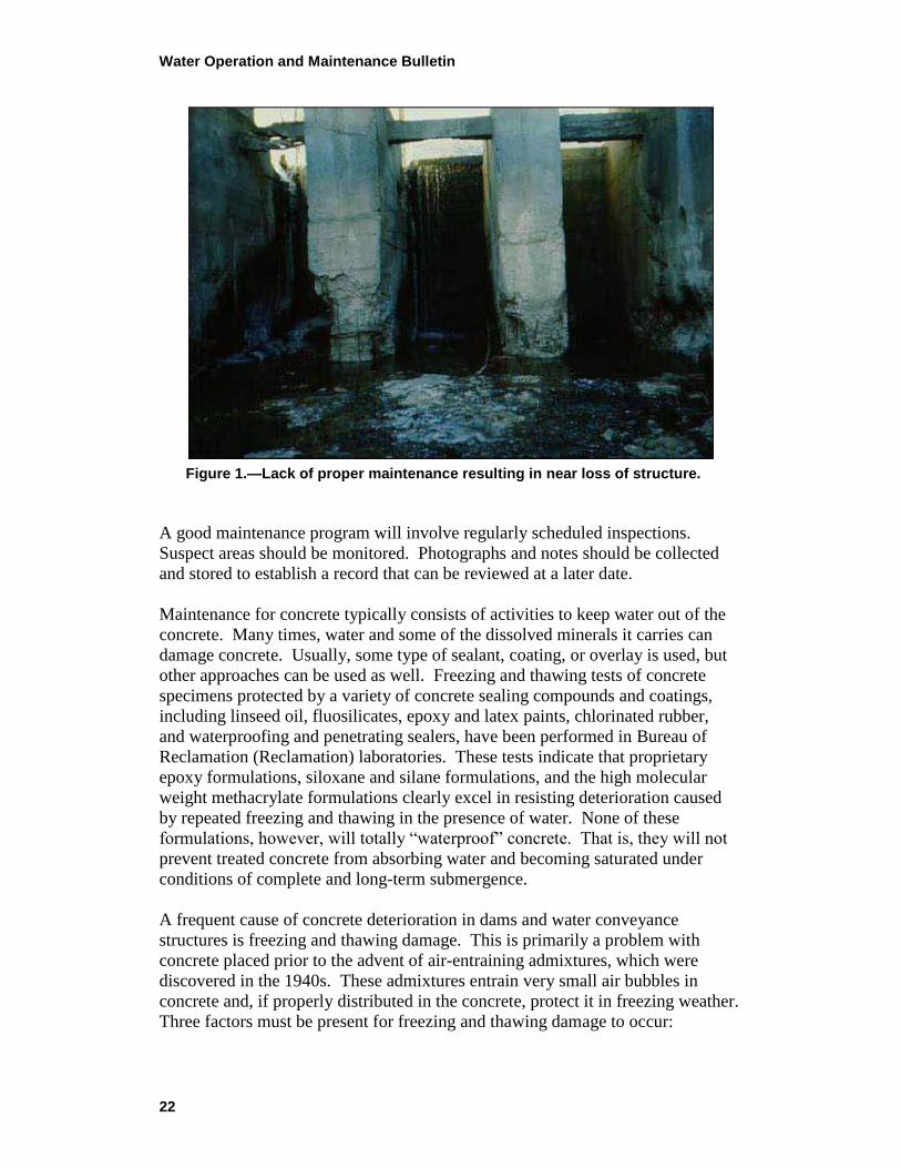
otherwise useful structures (figure 1).
Water Operation and Maintenance Bulletin
22
Figure 1.—Lack of proper maintenance resulting in near loss of structure.
A good maintenance program will involve regularly scheduled inspections.
Suspect areas should be monitored. Photographs and notes should be collected
and stored to establish a record that can be reviewed at a later date.
Maintenance for concrete typically consists of activities to keep water out of the
concrete. Many times, water and some of the dissolved minerals it carries can
damage concrete. Usually, some type of sealant, coating, or overlay is used, but
other approaches can be used as well. Freezing and thawing tests of concrete
specimens protected by a variety of concrete sealing compounds and coatings,
including linseed oil, fluosilicates, epoxy and latex paints, chlorinated rubber,
and waterproofing and penetrating sealers, have been performed in Bureau of
Reclamation (Reclamation) laboratories. These tests indicate that proprietary
epoxy formulations, siloxane and silane formulations, and the high molecular
weight methacrylate formulations clearly excel in resisting deterioration caused
by repeated freezing and thawing in the presence of water. None of these
formulations, however, will totally ―waterproof‖ concrete. That is, they will not
prevent treated concrete from absorbing water and becoming saturated under
conditions of complete and long-term submergence.
A frequent cause of concrete deterioration in dams and water conveyance
structures is freezing and thawing damage. This is primarily a problem with
concrete placed prior to the advent of air-entraining admixtures, which were
discovered in the 1940s. These admixtures entrain very small air bubbles in
concrete and, if properly distributed in the concrete, protect it in freezing weather.
Three factors must be present for freezing and thawing damage to occur:
Water Operation and Maintenance Bulletin
23
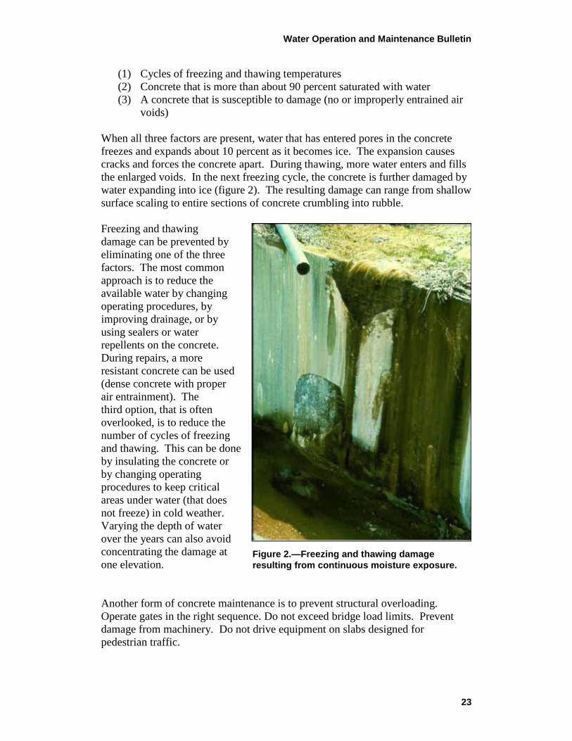
Figure 2.—Freezing and thawing damage
resulting from continuous moisture exposure.
(1) Cycles of freezing and thawing temperatures
(2) Concrete that is more than about 90 percent saturated with water
(3) A concrete that is susceptible to damage (no or improperly entrained air
voids)
When all three factors are present, water that has entered pores in the concrete
freezes and expands about 10 percent as it becomes ice. The expansion causes
cracks and forces the concrete apart. During thawing, more water enters and fills
the enlarged voids. In the next freezing cycle, the concrete is further damaged by
water expanding into ice (figure 2). The resulting damage can range from shallow
surface scaling to entire sections of concrete crumbling into rubble.
Freezing and thawing
damage can be prevented by
eliminating one of the three
factors. The most common
approach is to reduce the
available water by changing
operating procedures, by
improving drainage, or by
using sealers or water
repellents on the concrete.
During repairs, a more
resistant concrete can be used
(dense concrete with proper
air entrainment). The
third option, that is often
overlooked, is to reduce the
number of cycles of freezing
and thawing. This can be done
by insulating the concrete or
by changing operating
procedures to keep critical
areas under water (that does
not freeze) in cold weather.
Varying the depth of water
over the years can also avoid
concentrating the damage at
one elevation.
Another form of concrete maintenance is to prevent structural overloading.
Operate gates in the right sequence. Do not exceed bridge load limits. Prevent
damage from machinery. Do not drive equipment on slabs designed for
pedestrian traffic.
Water Operation and Maintenance Bulletin
24
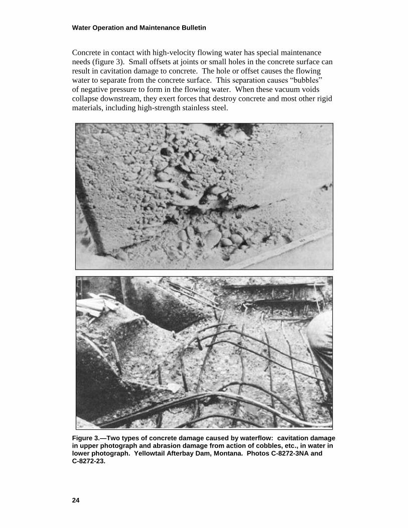
Concrete in contact with high-velocity flowing water has special maintenance
needs (figure 3). Small offsets at joints or small holes in the concrete surface can
result in cavitation damage to concrete. The hole or offset causes the flowing
water to separate from the concrete surface. This separation causes ―bubbles‖
of negative pressure to form in the flowing water. When these vacuum voids
collapse downstream, they exert forces that destroy concrete and most other rigid
materials, including high-strength stainless steel.
Figure 3.—Two types of concrete damage caused by waterflow: cavitation damage in upper photograph and abrasion damage from action of cobbles, etc., in water in lower photograph. Yellowtail Afterbay Dam, Montana. Photos C-8272-3NA and C-8272-23.
Water Operation and Maintenance Bulletin
25
The newly damaged area causes more separation of flowing water, and cavitation
damage will occur downstream from the most recently damaged area. This
results in a series of damaged areas, each getting larger, downstream from the
original offset. Proper concrete maintenance in high-velocity waterflow
structures includes eliminating offsets and holes and repairing observed cavitation
damage before it can enlarge to destroy the entire structure. Since no material
will stand up to cavitation for a long time, the long-term solution is to manage
the flow to avoid flows that will cause cavitation.
Another area of concrete maintenance is preventing abrasion damage. Flowing
water, even at velocities too low for cavitation damage, can destroy concrete
structures by the impact and grinding action of sand and rock carried in the water.
Proper maintenance means reducing the amount of sand and rock in flowing
water. Screens or settling areas at inlet structures can help. Retaining walls to
protect flowing water from rock slides and fences to keep people from throwing
rocks into the water are sometimes needed. Removing material from stilling
basins should be a part of routine maintenance.
Concrete Repair
In spite of good maintenance, there will always be some structures requiring
concrete repair. There are three choices when deciding on a repair. A permanent
repair to attempt to return the structure to its original condition and function is a
common approach. In some cases, however, a temporary repair is justified by its
lower cost. Temporary repairs are used when a structure will soon be replaced,
but must serve a few more seasons, or when funding is not available for a
permanent repair. The third option of deciding to make no repair is often
overlooked. Not all concrete with visible damage needs to be repaired. A
spillway floor that has lost a fraction of an inch of concrete due to abrasion over
the last 30 years will likely serve another 30 years without repair. In this case, the
original concrete is of good quality and will likely serve better than any attempted
thin repair material.
Cause of Damage
Before selecting a specific repair method, the cause and extent of concrete
damage should be determined. Knowing what caused the damage and reducing or
eliminating that cause will make the repair last longer. If no attempt is made to
eliminate the original cause of damage, the repair will likely fail as the original
concrete did. Freezing and thawing damage, structural overloading, cavitation
damage, and abrasion damage have been discussed above. Sulfate-bearing waters
or soils and alkali-aggregate reaction can also attack concrete. Design and
construction defects can result in concrete damage due to improperly shaped flow
areas, foundation settlement, weak concrete, poor finishing, structural
Water Operation and Maintenance Bulletin
26
overloading, poor curing, and other causes. Some concrete simply suffers from
old age. All construction materials deteriorate eventually. Good design,
construction, and maintenance will lengthen service life. Good concrete can last
hundreds or thousands of years. Some Roman concrete structures, including the
Pantheon and some aqueducts, are still functional after 2,000 years.
Causes of concrete deterioration and failure can be grouped into three general
categories:
(1) Planning, design, or construction deficiencies. – These causes of
failure could be due to inadequate foundation explorations, structural
shortcomings due to improper design, omissions in operating criteria,
inadequate construction supervision resulting in poor quality materials,
etc. Also, improper selection of construction materials can result in
alkali-aggregate reactions, chemical attack from sulfates in soil or ground
water, freeze-thaw damage, and structural failures.
(2) Unforeseen conditions. – Such unexpected conditions as floods, storms,
earth and rock slides, lightning, etc., can cause minor to severe damage to
concrete structures.
(3) Natural attrition and old age. – All materials of construction are subject
to aging and, concurrently, weathering and deterioration. The severity of
the weathering process will depend upon the climatic conditions to which
a structure is subjected as well as the type and quality of the original
materials of which it was constructed.
Extent of Damage
Knowing the extent of damage is also necessary when planning a concrete repair.
A shallow surface repair will not be effective if the damage extends deep into the
concrete. Knowing the extent of damage will also help in confirming and
mitigating the cause. Removing cores from the concrete is an excellent method of
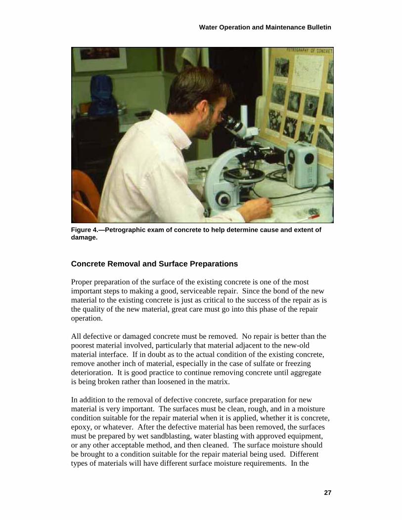
determining the extent of damage. Visual examination, petrographic examination
(figure 4), and mechanical testing of concrete cores can give reliable information
on the cause and extent of damage. Coring and testing are expensive and
sometimes not justified for small repair jobs. Simple methods such as the
rebound hammer, geologist pick, steel rod, and chain drag can frequently be
effective in locating weak and delaminated areas of concrete. When major
concrete repairs on significant structures are planned, high technology non-
destructive methods such as acoustic testing and radar are sometimes used in
condition assessment.
Water Operation and Maintenance Bulletin
27
Figure 4.—Petrographic exam of concrete to help determine cause and extent of damage.
Concrete Removal and Surface Preparations
Proper preparation of the surface of the existing concrete is one of the most
important steps to making a good, serviceable repair. Since the bond of the new
material to the existing concrete is just as critical to the success of the repair as is
the quality of the new material, great care must go into this phase of the repair
operation.
All defective or damaged concrete must be removed. No repair is better than the
poorest material involved, particularly that material adjacent to the new-old
material interface. If in doubt as to the actual condition of the existing concrete,
remove another inch of material, especially in the case of sulfate or freezing
deterioration. It is good practice to continue removing concrete until aggregate
is being broken rather than loosened in the matrix.
In addition to the removal of defective concrete, surface preparation for new
material is very important. The surfaces must be clean, rough, and in a moisture
condition suitable for the repair material when it is applied, whether it is concrete,
epoxy, or whatever. After the defective material has been removed, the surfaces
must be prepared by wet sandblasting, water blasting with approved equipment,
or any other acceptable method, and then cleaned. The surface moisture should
be brought to a condition suitable for the repair material being used. Different
types of materials will have different surface moisture requirements. In the
Water Operation and Maintenance Bulletin
28
process of preparing the surfaces, care must be taken to prevent undercutting of
aggregate in the existing concrete. It is advisable in the case of very old structures
to wait several days after completing the surface preparation before applying the
new material. Sometimes, concrete in old structures seems sound when cleaned,
but will slake and soften after a few days’ exposure. Care must be exercised to
see that the cleaned and prepared concrete surfaces are maintained in that
condition until repairs are made. Water seeps may be stopped by lead wool
caulking or by cover drains. These may lead to sumps, to permanent weep holes,
or to a vacuum system. Chemical grouting can also be used successfully,
especially where leaks are from very fine cracks that are difficult to follow
accurately with a routing tool, or in coarse, porous areas that are seeping. Any
method of sealing that can be accomplished without contaminating the adjacent
area is suitable for this work.
Repair Methods
Some basic concrete repair methods are discussed below. For a more extensive
list of options and more technical details of repair, consult the most current
edition of Standard Specifications for Repair of Concrete, M-47, Reclamation.
Also, the Guide to Concrete Repair, published in 1996 by Reclamation, contains
good information about maintenance and repair of concrete.
Concrete replacement—replacing a portion of the concrete in a structure without
the use of a bonding agent—is one of the most effective concrete repair methods.
It is used for large areas that are over 6 inches deep. Repairs of this size and
depth usually retain moist curing conditions at the interface between new and old
concrete for many weeks and, thus, develop a good bond. When concrete damage
is less that 6 inches deep, it is sometimes still economical to excavate to a depth
of 6 inches or more and use the concrete replacement method rather than using
thinner repair methods that can be more difficult, more expensive, and less
durable.
Dry pack is effective for small, deep repairs with nearly vertical edges such as
core holes, form bolt holes, and slots. Dry pack is a mixture of cement, fine sand,
and very little water. It is rich in cement, but has little shrinkage because of the
low water content. After the hole has been prepared, the dry pack material is
pounded into place in thin layers with a wooden rod to assure complete
compaction. Continuous moist curing for at least 14 days is required to assure
that the little water used in the dry pack is not lost and is available for cement
hydration.
Mortar replacement is used in areas too wide for dry pack and too shallow for
concrete replacement. It is simply Portland cement mortar placed either by hand
Water Operation and Maintenance Bulletin
29
or pneumatically with shotcrete equipment. This repair works best on new, green
concrete (less than 24 hours old) that is still actively hydrating—thus, assuring
good bonding between the repair and the base concrete.
There are cases when it is feasible to repair deteriorated or damaged concrete by
plastering with mortar. This can be done by hand; but more often than not, it is
done pneumatically and is called shotcrete. Considerable skill is required by the
operators to assure a quality repair since they have control of the amount of
moisture in the placement and the application. It can be difficult to get a pleasing
finish using shotcrete; however, a satisfactory finish may be obtained by lightly
rubbing the surface with a soft rag or burlap immediately after application.
Epoxy bonded concrete is used for repairs between 1½ inches and 6 inches in
depth. It is essentially like the concrete replacement method, but because of the
shallow depth, an epoxy bonding agent meeting ASTM C-881 requirements is
used to assure good bond to the old concrete.
Epoxy bonded epoxy mortar is used for repairs less than 1½ inches in depth.
Epoxy is used both as the bonding agent and as the cementing agent in the mortar.
Epoxy mortar contains epoxy and sand. It contains no Portland cement and no
water. While epoxy mortar is a strong, durable material, it sometimes disbonds
from the substrate concrete when exposed to large temperature changes because
its rate of thermal expansion is much different from that for concrete. Thus, if
epoxy bonded epoxy mortar is used in an outdoor environment, it will likely
become unbonded sometime in the future. Epoxy mortar repairs covering large
areas on concrete slabs on grade sometimes trap rising moisture under the repair
and then fail when the moisture freezes and expands. Epoxy bonded epoxy
mortar repairs should not be used where there will be large temperature changes
or where moisture can be trapped under the repair and subjected to freezing.
Silica fume concrete is the repair material of choice for applications requiring
enhanced abrasion-erosion resistance and/or reduced permeability. Silica fume
concrete is conventional Portland cement concrete containing admixtures of silica
fume. Silica fume is a finely divided powder byproduct resulting from the use of
electric arc furnaces. When mixed with Portland cement concrete, silica fume
acts as a ―super pozzolan.‖ Concrete containing 5-to 15-percent silica fume by
mass of cement commonly can develop 10,000-to 15,000-pound-per-square-inch
compressive strengths, reduced tendency to segregate, very low permeabilities,
and enhanced freeze-thaw and abrasion-erosion resistance. Placing, finishing, and
curing silica fume concrete is somewhat different than conventional concrete and
should not be used until those differences are planned for. Otherwise, this repair
material is used according to the provisions for conventional replacement
concrete.
The above repair techniques give basic repair options for concrete based on the
dimensions of the repair area. There are numerous other materials currently used
Water Operation and Maintenance Bulletin
30
in concrete repair including polymer concrete, silica fume concrete, and many
versions of modified Portland cement concretes. The basic repair principles
remain the same. Thicker and more massive repairs reduce the need for bonding
agents and increase the chances of a durable repair. Thin repairs need bonding
agents, but still have more chance of failure.
Repairing cracks in concrete requires different techniques. Narrow cracks can be
repaired by filling with epoxy if the cracks are relatively dry and not moving.
With proper technique, the structural integrity of the concrete can be restored.
The crack is temporarily sealed along the concrete surface, leaving gaps for
injections points and for air to exit. An epoxy material meeting requirements of
ASTM C-881 is used for the structural repair. On large jobs, two pumps are used,
one for each part of the two-part epoxy. The epoxy components are pumped
through separate hoses to a mixing head where they mix and exit a single tube.
The tube is connected to injection ports installed along the crack. When the crack
is completely filled and the epoxy cures, the concrete sections are structurally
bonded. On smaller jobs, simpler injection methods can be used such as pressure
pots, caulking guns, or squeeze bottles.
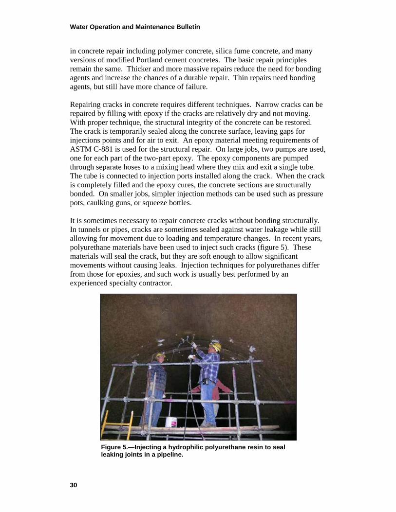
It is sometimes necessary to repair concrete cracks without bonding structurally.
In tunnels or pipes, cracks are sometimes sealed against water leakage while still
allowing for movement due to loading and temperature changes. In recent years,
polyurethane materials have been used to inject such cracks (figure 5). These
materials will seal the crack, but they are soft enough to allow significant
movements without causing leaks. Injection techniques for polyurethanes differ
from those for epoxies, and such work is usually best performed by an
experienced specialty contractor.
Figure 5.—Injecting a hydrophilic polyurethane resin to seal leaking joints in a pipeline.
Water Operation and Maintenance Bulletin
31
Conclusions
Every facet or phase of concrete repair is important and critical to the success
of the final product. Workmanship, material selection and treatment, and
maintenance are all areas that, if properly considered, will ensure that a
serviceable, long-life repair has been made. Large concrete repairs over 6 inches
in depth, using Portland cement concrete and no bonding agent, are usually the
most durable and, sometimes, the most economical. Thin repairs, while some-
times necessary, often use more expensive materials, more difficult techniques,
and result in less durability. It is sometimes economical to overexcavate
shallow areas of deterioration in order to make a deeper, longer-lasting repair.
Conventional concrete should be the first choice for concrete repairs. Other
materials should be used only where it can be shown that conventional concrete
will fail. While good quality original construction concrete is usually superior to
any repair, repairs of sufficient quality to greatly extend a structure’s life can be
made with the techniques discussed.
In conclusion, and to verify some of the statements made herein through the
writings of an old water works operator, the following is quoted:
Requirements for Good Concrete – Repairs that can be carried on
without cutting off the water of the aqueducts consist principally of
masonry work, which should be executed at the right time, and
conscientiously. The proper time for masonry work is from the
first of April to the first of November; but with this restriction:
That the work be interrupted during the hottest part of the summer;
because moderate weather is necessary for the masonry properly
to absorb the mortar and to solidify into one compact mass; for the
heat of the sun is no less destructive to masonry than is too violent
frost. Nor is greater care required upon any works than upon such
as are to withstand the action of water; for this reason, all parts of
the work need to be done exactly according to the rules of art,
which all the workmen know, but few observe.
Excerpted from the Water Supply of the City
of Rome of Sextus Julius Frontinus, Water
Commissioner of the City of Rome, A.D. 97
33
Visual Checklist for Canal Embankment and Repairs
As a result of conditions possibly threatening the structural integrity of a canal
embankment (e.g., seepage, subsidence, displacement, etc.), periodic monitoring
is often prudent and recommended. This is particularly important in order to
identify the timing of additional actions to take to reduce/minimize the likelihood
of failure and to begin and assist with the notification process related to
emergency management activities. The following is an example of a visual
inspection checklist that Reclamation and several of its water user operating
entities have utilized in the recent past to monitor and document items of concern
associated with canal embankments. The checklist can also be used to monitor
canal embankment conditions, during the watering-up process of the canal,
following repairs to a canal embankment.
The checklist can and should be revised to make it specific to local conditions and
particular structures of concern. The frequency of monitoring and completing the
checklist will also be dictated by the extent and progress of the particular
conditions affecting the canal embankment.
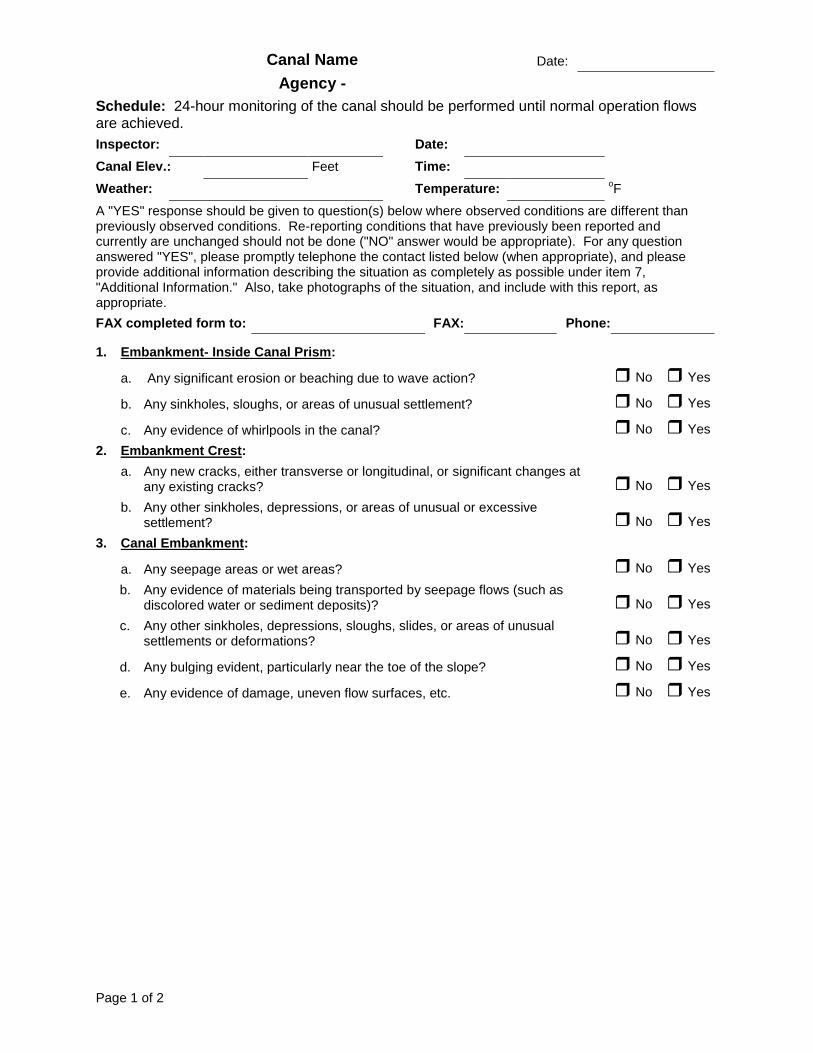
Page 1 of 2
Canal Name Date:
Agency -
Schedule: 24-hour monitoring of the canal should be performed until normal operation flows are achieved.
Inspector: Date:
Canal Elev.: Feet Time:
Weather: Temperature: oF
A "YES" response should be given to question(s) below where observed conditions are different than previously observed conditions. Re-reporting conditions that have previously been reported and currently are unchanged should not be done ("NO" answer would be appropriate). For any question answered "YES", please promptly telephone the contact listed below (when appropriate), and please provide additional information describing the situation as completely as possible under item 7, "Additional Information." Also, take photographs of the situation, and include with this report, as appropriate.
FAX completed form to: FAX: Phone:
1. Embankment- Inside Canal Prism:
a. Any significant erosion or beaching due to wave action? No Yes
b. Any sinkholes, sloughs, or areas of unusual settlement? No Yes
c. Any evidence of whirlpools in the canal? No Yes
2. Embankment Crest:
a. Any new cracks, either transverse or longitudinal, or significant changes at any existing cracks? No Yes
b. Any other sinkholes, depressions, or areas of unusual or excessive settlement? No Yes
3. Canal Embankment:
a. Any seepage areas or wet areas? No Yes
b. Any evidence of materials being transported by seepage flows (such as discolored water or sediment deposits)? No Yes
c. Any other sinkholes, depressions, sloughs, slides, or areas of unusual settlements or deformations? No Yes
d. Any bulging evident, particularly near the toe of the slope? No Yes
e. Any evidence of damage, uneven flow surfaces, etc. No Yes
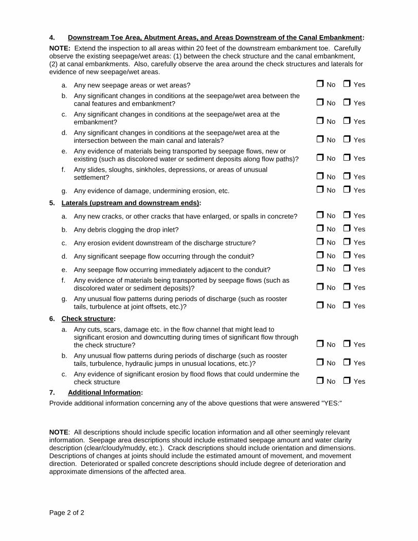
Page 2 of 2
4. Downstream Toe Area, Abutment Areas, and Areas Downstream of the Canal Embankment:
NOTE: Extend the inspection to all areas within 20 feet of the downstream embankment toe. Carefully observe the existing seepage/wet areas: (1) between the check structure and the canal embankment, (2) at canal embankments. Also, carefully observe the area around the check structures and laterals for evidence of new seepage/wet areas.
a. Any new seepage areas or wet areas? No Yes
b. Any significant changes in conditions at the seepage/wet area between the canal features and embankment? No Yes
c. Any significant changes in conditions at the seepage/wet area at the embankment? No Yes
d. Any significant changes in conditions at the seepage/wet area at the intersection between the main canal and laterals? No Yes
e. Any evidence of materials being transported by seepage flows, new or existing (such as discolored water or sediment deposits along flow paths)? No Yes
f. Any slides, sloughs, sinkholes, depressions, or areas of unusual settlement? No Yes
g. Any evidence of damage, undermining erosion, etc. No Yes
5. Laterals (upstream and downstream ends):
a. Any new cracks, or other cracks that have enlarged, or spalls in concrete? No Yes
b. Any debris clogging the drop inlet? No Yes
c. Any erosion evident downstream of the discharge structure? No Yes
d. Any significant seepage flow occurring through the conduit? No Yes
e. Any seepage flow occurring immediately adjacent to the conduit? No Yes
f. Any evidence of materials being transported by seepage flows (such as discolored water or sediment deposits)? No Yes
g. Any unusual flow patterns during periods of discharge (such as rooster tails, turbulence at joint offsets, etc.)? No Yes
6. Check structure:
a. Any cuts, scars, damage etc. in the flow channel that might lead to significant erosion and downcutting during times of significant flow through the check structure? No Yes
b. Any unusual flow patterns during periods of discharge (such as rooster tails, turbulence, hydraulic jumps in unusual locations, etc.)? No Yes
c. Any evidence of significant erosion by flood flows that could undermine the check structure No Yes
7. Additional Information:
Provide additional information concerning any of the above questions that were answered "YES:"
NOTE: All descriptions should include specific location information and all other seemingly relevant information. Seepage area descriptions should include estimated seepage amount and water clarity description (clear/cloudy/muddy, etc.). Crack descriptions should include orientation and dimensions. Descriptions of changes at joints should include the estimated amount of movement, and movement direction. Deteriorated or spalled concrete descriptions should include degree of deterioration and approximate dimensions of the affected area.
Mission
The mission of the Bureau of Reclamation is to manage, develop, and protect
water and related resources in an environmentally and economically
sound manner in the interest of the American public.
The purpose of this bulletin is to serve as a medium of exchanging operation and
maintenance information. Its success depends upon your help in obtaining and
submitting new and useful operation and maintenance ideas.
Advertise your district’s or project’s resourcefulness by having an article published in
the bulletin—let us hear from you soon!
Prospective articles should be submitted to one of the Bureau of Reclamation contacts
listed below:
Darrel Krause, Bureau of Reclamation, ATTN: 84-57000, PO Box 25007,
Denver, CO 80225-0007; (303) 445-2941; email: [email protected]
Kenneth Schwairy, Bureau of Reclamation, ATTN: 86-68360, PO Box 25007,
Denver, CO 80225-0007; (303) 445-3015; email: [email protected]
James Dean, Pacific Northwest Region, ATTN: PN-3200, 1150 North Curtis
Road, Boise, ID 83706-1234; (208) 378-5398; email: [email protected]
Paul Caruso, Mid-Pacific Region, ATTN: MP-4300, 2800 Cottage Way,
Sacramento, CA 95825-1898; (916) 978-5224; email: [email protected]
Scott Foster, Lower Colorado Region, ATTN: LC-6600, PO Box 61470,
Boulder City, NV 89006-1470; (702) 293-8144; email: [email protected]
Rick Scott, Upper Colorado Region, ATTN: UC-1000, PO Box 11568,
Salt Lake City, UT 84147-0568; (801) 524-3726; email: [email protected]
Dave Nelson, Great Plains Region, ATTN: GP-2400, PO Box 36900,
Billings, MT 59107-6900; (406) 247-7630; email: [email protected]