water main project expectations manualwater main project expectations thrust restraint (cont.)...
TRANSCRIPT

WATER MAIN PROJECT EXPECTATIONS MANUAL
Guide for the Design and Installation of Small Diameter Water Main Projects
City of Lincoln, Engineering Services Lincoln Water System September 2013
CITY OF LINCOLN ENGINEERING SERVICES

949 W. Bond St. • 441-7711/441-6576 (fax) www. lincoln. ne. gov
-1-
City of Lincoln - Engineering Services Water Main Project Expectations
INTRODUCTION
Lincoln Water System mains are designed to provide adequate flows for domestic and commercial uses and for fire protection, to protect the quality of the public water supply, and to maintain the in-tegrity and reliability of the distribution system.
The City of Lincoln Water System is regulated by the requirements of the Federal and State SafeDrinking Water Acts. Design and construction of facilities for the City’s system shall generally follow the standards of the American Water Works Association (AWWA) and the Recommended 10-State Standards for Water Works. Details of construction shall conform to the City of Lincoln Specifica-tions for Municipal Construction and the Lincoln Standard Plans.
The purpose of this manual is to supplement the information and specifications listed above for Field Personnel, Project Managers, Engineers and Designers to help facilitate the successful design and construction of small diameter water main projects in the City of Lincoln. For the purpose of this manual, small diameter mains shall be defined as those mains ranging from 6” to 16” in size.
949 W. Bond St. • 441-7711/441-6576 (fax) www. lincoln. ne. gov
-2-
City of Lincoln - Engineering Services Water Main Project Expectations
RECEIVING
Inspection for damage and defects The City may require that materials furnished by the Contractor be subject to inspection and ac-ceptance by the City at the manufacturer’s plant or at the point of delivery. The City may request additional test results or affidavits of compliance as specified in ANSI/AWWA C900 and ANSI/AWWA C905, to ensure conformance. Inspection by the City does not relieve the Contractor of responsibility to inspect and accept the materials.
ResponsibilityThe Contractor shall be responsible for materials provided by the Contractor. He/she shall re-place at no additional expense, any materials found by the City to be defective in manufacture or damaged from any result at any time. This shall include all labor, materials, and equipment re-quired for the replacement of installed defective material.
City provided materials The Contractor’s responsibility for materials provided by the City shall begin at the point of pick-up by the Contractor at the City yard. Materials already on site shall, on acceptance by the Con-tractor, become the Contractor’s responsibility on the day work commences or the day designated by the City. However, latent defects of the material which are not identifiable by physical inspec-tion, shall remain the responsibility of the City even after acceptance by the Contractor. Defective City provided material which has been installed shall be replaced by the City.
RejectionOn receipt, material found to be defective due to manufacture or damage in shipment shall be re-jected and recorded on the bill of lading and removed from the jobsite. The Contractor shall in-spect materials provided by the City and shall reject defective materials at the time of receipt. Any observed gouges or scratches that extend 10 percent or more into the pipe wall shall justify rejection of that pipe. The Contractor may use the undamaged portion of a pipe by cutting off the damaged section. However, any additional fittings required due to the salvage of said pipe shall be installed at Contractor’s expense. Defective materials shall be clearly marked, segregated, and removed from the site.
STANDARD PROCEDURE FOR RECEIVING, HANDLING AND STORAGE OF PIPE
949 W. Bond St. • 441-7711/441-6576 (fax) www. lincoln. ne. gov
-3-
City of Lincoln - Engineering Services Water Main Project Expectations
HANDLING
Unloading and loading The Contractor shall be responsible for unloading and loading of materials at the jobsite. To avoid damage, pipe and appurtenances shall be loaded and unloaded with care and in accordance with the manufacturer’s published recommendations. Adherence to those recommendations is partic-ularly important when temperatures are below 32 deg. F (0 deg. C). Under no circumstances shall such material be dropped. Special care shall be given to pipe gaskets to prevent damage from handling operations.
HaulingWhen hauling materials at the jobsite, care shall be exercised to prevent damage. When possible, pipe shall be hauled in unit packages with proper supports.
PaddingSlings (other than nylon straps), hooks, or pipe tongs shall be padded and used properly to pre-vent damage to pipe and appurtenances.
STORAGE
Care of Stored Pipe Stored material shall be kept safe from damage. The interior as well as sealing surfaces of pipe and appurtenances shall be kept free from dirt and foreign matter per ANSI/AWWA C651. Pipe stored outdoors and expected to be exposed to direct sunlight for periods of one year or more after deliv-ery shall be covered with canvas or other opaque material with provision for adequate air circula-tion. PVC pipe shall not be stored close to heat sources, such as heaters, boilers, steam lines, or en-gine exhaust. Special care shall be given to pipe gaskets to prevent damage from UV exposure dur-ing long-term storage.
StackingWhen possible, pipe shall be stored in unit packages on flat surfaces to avoid bending. When unit
packages are stacked, care shall be exercised to ensure that the weight of the upper units does not cause deformation to pipe in lower units. Packages shall be supported by racks or dunnage to pre-vent damage or bending of the pipe. Care shall be exercised to ensure that the height of the stack does not result in instability that could cause stack collapse, pipe damage, or personal injury. Gen-erally, stack height should not exceed 8 feet. Safe stack height will vary by unit package configura-tion.
STANDARD PROCEDURE FOR RECEIVING, HANDLING AND STORAGE OF PIPE (cont.)

949 W. Bond St. • 441-7711/441-6576 (fax) www. lincoln. ne. gov
-4-
City of Lincoln - Engineering Services Water Main Project Expectations
Protecting Gaskets Gaskets shall be protected at all times from excessive exposure to heat, direct sunlight, ozone (from electric motors & equipment), oil, grease, or other contaminants. Any faded, ripped, torn, loss of elasticity or otherwise questionable gaskets shall not be installed or used on the project.
StringingIn preparation for installation, distribution (stringing) of pipe and appurtenances shall be as close to the trench as practical and, if possible, on the opposite side from the excavated earth stockpile. Pipe shall be protected from traffic and secured to prevent rolling. Bell ends on pipe should be pointed in the direction of work progress. Caution shall be exercised to minimize contamination of pipe interiors and joint components.
STANDARD PROCEDURE FOR RECEIVING, HANDLING AND STORAGE OF PIPE (cont.)
STORAGE (cont.)

949 W. Bond St. • 441-7711/441-6576 (fax) www. lincoln. ne. gov
-5-
City of Lincoln - Engineering Services Water Main Project Expectations
THRUST RESTRAINT
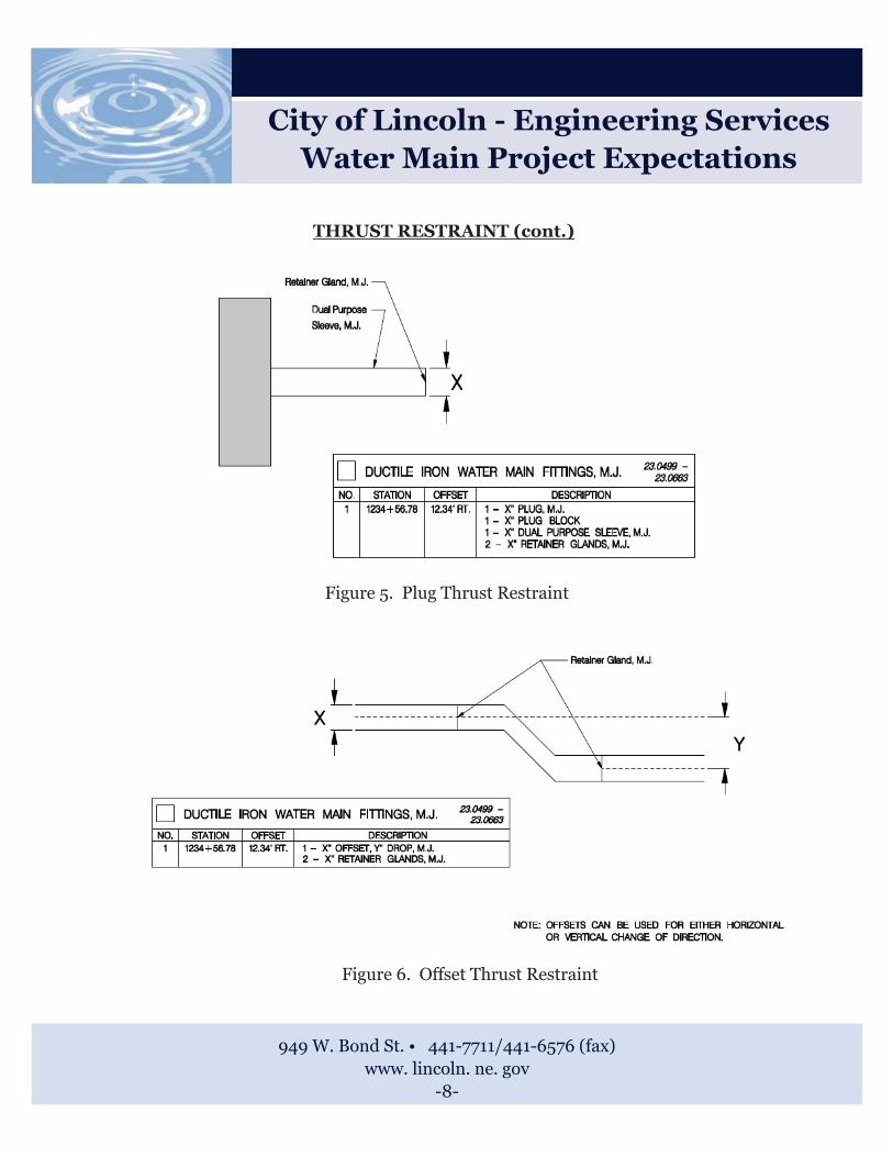
Installation of proper thrust restraint for pipe and fittings on small diameter water main projects is key to system stability and longevity. The Lincoln Water System standard is to restrain horizontal de-flections and offset fittings, through the use of precast concrete (L-3500) thrust blocks and retainer glands. The standard for the restraint of vertical deflections is through the use of gravity blocks with steel restraining straps. Thrust blocks shall cure a minimum of 72 hours before being subjected to water main pressure. Thrust blocks shall be formed to prevent excess concrete from spilling over on-to the fittings. The following figures show examples of typical fitting installations and the appropriate restraint needed in each case. While these examples show how to restrain fittings for the majority of situations they should not be considered all encompassing and each fitting installation should be ana-lyzed on a case by case basis. For further details regarding thrust restraint sizes, materials or quanti-ties refer to Lincoln Standard Plan (LSP) 320.
Typical Horizontal Deflection Thrust Restraint
Figure 1. Horizontal Bend Thrust Restraint

949 W. Bond St. • 441-7711/441-6576 (fax) www. lincoln. ne. gov
-6-
City of Lincoln - Engineering Services Water Main Project Expectations
THRUST RESTRAINT (cont.)
Figure 2a. Tee Thrust Restraint
Figure 2b. Tee Thrust Restraint

949 W. Bond St. • 441-7711/441-6576 (fax) www. lincoln. ne. gov
-7-
City of Lincoln - Engineering Services Water Main Project Expectations
THRUST RESTRAINT (cont.)
Figure 3. Valve Thrust Restraint
Figure 4. Cross Thrust Restraint
949 W. Bond St. • 441-7711/441-6576 (fax) www. lincoln. ne. gov
-8-
City of Lincoln - Engineering Services Water Main Project Expectations
THRUST RESTRAINT (cont.)
Figure 5. Plug Thrust Restraint
Figure 6. Offset Thrust Restraint

949 W. Bond St. • 441-7711/441-6576 (fax) www. lincoln. ne. gov
-9-
City of Lincoln - Engineering Services Water Main Project Expectations
THRUST RESTRAINT (cont.)
Figure 7. Vertical Thrust Restraint
Typical Vertical Deflection Thrust Restraint
Gravity block straps of the size and type specified in the Lincoln Standard Plans shall be State Steel type M1020, or equivalent, low carbon, low manganese, general purpose, merchant quality stainless steel that is suitable for forming and welding. All strap material not embedded in concrete shall be covered with polywrap or tape prior to backfilling.

949 W. Bond St. • 441-7711/441-6576 (fax) www. lincoln. ne. gov
-10-
City of Lincoln - Engineering Services Water Main Project Expectations
TRACER WIRE
The Contractor shall install tracer wire for small diameter PVC water main projects. It is important that tracer wire is installed properly on pipe projects so that the main can be properly located and marked in the field in the future. Proper location of the main through the use of tracer wire helps to minimize the potential that damage will occur due to other utility work. The following list of items can be used as guidance for field personnel when tracer wire is installed with PVC mains.
�� Wire used for location of PVC pipe shall be 12 gage AWG-THNN solid copper with insulation thickness of 0.030”.
�� Wire shall be attached directly to the top of the pipe between the 10 o’clock and 2 o’clock posi-tions. Attachment should be with small tape patches as shown in Figure 1 below. Wire should be secured so that some slack can be taken out of the wire for valve and tap installations.
Figure 1. Tracer Wire Installation Detail

949 W. Bond St. • 441-7711/441-6576 (fax) www. lincoln. ne. gov
-11-
City of Lincoln - Engineering Services Water Main Project Expectations
TRACER WIRE (cont.)
�� Provide access to wire per the following:
- In both line valves and hydrant branch valves
- Wire shall be attached to the exterior of the valve box.
- Wire shall be inserted into the valve box eight inches from the top of the box through a field drilled 1/2” hole.
- At hydrants when a branch is greater than ten (10) feet in length
- Drainage & Water Solutions, Inc. tracer wire termination box, shown in Figure 1 be low, or equal, shall be placed at grade next to the street side of the hydrant. Wires shall be attached to the termination screws.
- Drainage & Water Solutions, Inc. tracer wire termination box shall be complete with factory lid stamped as “Water”, as shown in Figure 2 below.
- Wire shall be attached to hydrant barrel with tape.
Figure 1. DWS Wire Termination Box Figure 2. DWS Wire Termination Box Lid

949 W. Bond St. • 441-7711/441-6576 (fax) www. lincoln. ne. gov
-12-
City of Lincoln - Engineering Services Water Main Project Expectations
TRACER WIRE (cont.)
- All wire accesses shall consist of a looped spool of wire with a minimum lead length of eight- een (18) inches which provides trace capabilities in each direction.
- 1” of insulation shall be stripped at the access loop for contact with tracing equipment.
�� Wire splices shall be 3M DBR connectors, sealed with silicone sealant, or equal and covered with Scotch #33 electrical tape. No bare wire shall be exposed. The two ends of the wire shall be knot-ted to prevent strain on the splice. Branch connections shall be made without cutting the main wire utilizing a connection clip and sealing the joint the same as splices. Figures 3 and 4 shown below show the 3m DBR connectors and connection clip.
Figure 3. 3M DBR Splice Connector Kit Figure 4. Wire Connection Clip

949 W. Bond St. • 441-7711/441-6576 (fax) www. lincoln. ne. gov
-13-
City of Lincoln - Engineering Services Water Main Project Expectations
STANDARD PROCEDURE FOR ALLOWING TRENCHLESS CONSTRUCTION IN PLACE OF OPEN CUT CONSTRUCTION
During most Water Main Construction projects, Contractors may feel that the use of trenchless tech-nologies would be a better method of installation than that of the open-cut design shown on the plans. The following steps shall be used as a standard procedure to approve such changes.
�� Step 1: Contractor shall notify the City of Lincoln Construction Project Manager and Project In-spector in writing of the request to be allowed to bore or directionally drill in an area shown as open cut on the plans. The request can be done by letter or email and should include the approxi-mate station range in question, timeframe for completing the work, and the expected change in price of the total contracted amount, including a detailed list of quantities that will be adjusted. The request shall also include a proposed bore log and profile which shows depths of proposed main and all utility crossings and proposed slopes on regular intervals. An example of a properly formatted request, bore log and profile are shown in Figures 1, 2 and 3 on the following pages.
�� Step 2: The Construction Project Manager shall forward the request to the City of Lincoln Design Project Manager. The Design Project Manager shall verify all information in the request. Vertical deflections shall be checked against allowable manufacturers standards for the pipe material in-stalled.
�� Step 3: The Design Project Manager shall forward the request to the appropriate Lincoln Water System representative for review and approval or denial of the request. LWS will issue a written statement of approval or denial and reasons for their decision back to the Design Project Manager within 24 to 48 hours.
�� Step 4: The Design Project Manager will convey approval or denial of the request to the Construc-tion Project Manager or to the Contractor directly and work shall proceed accordingly. All docu-mentation shall be copied and included in the project file. No work shall be commenced in the ar-ea in question until written approval from the Lincoln Water System and the City of Lincoln has been granted.

949 W. Bond St. • 441-7711/441-6576 (fax) www. lincoln. ne. gov
-14-
City of Lincoln - Engineering Services Water Main Project Expectations
STANDARD PROCEDURE FOR ALLOWING TRENCHLESS CONSTRUCTION IN PLACE OF OPEN CUT CONSTRUCTION (continued)
Figure 1. Example Request Letter

949 W. Bond St. • 441-7711/441-6576 (fax) www. lincoln. ne. gov
-15-
City of Lincoln - Engineering Services Water Main Project Expectations
STANDARD PROCEDURE FOR ALLOWING TRENCHLESS CONSTRUCTION IN PLACE OF OPEN CUT CONSTRUCTION (continued)
Figure 2. Example Bore Log

949 W. Bond St. • 441-7711/441-6576 (fax) www. lincoln. ne. gov
-16-
City of Lincoln - Engineering Services Water Main Project Expectations
STANDARD PROCEDURE FOR ALLOWING TRENCHLESS CONSTRUCTION IN PLACE OF OPEN CUT CONSTRUCTION (continued)
Figure 3. Example Bore Profile

949 W. Bond St. • 441-7711/441-6576 (fax) www. lincoln. ne. gov
-17-
City of Lincoln - Engineering Services Water Main Project Expectations
HYDRANT ORIENTATION AND GRADE
Hydrant orientation and grade continues to be an issue on small main water project installations in the City of Lincoln. The Lincoln Water System standard for orientation is for the large steamer hy-drant nozzle to face the adjacent roadway. This standard allows for easy access to hydrants for the City’s emergency responders and their equipment. Contractors typically have problems with improp-er installation due to lack of knowledge about which shoe configuration is needed for the various types of hydrants installed. Figures 1 and 2 show examples of installations with proper and improper hydrant orientation.
The Lincoln Water System standard for grade is for the bottom flange to be 6” above the finished grade of the ground. Contractors typically have problems with grade issues due to improper hydrant lengths specified on the plans or lack of flange elevation data shown. Figures 3 and 4 show examples of installations with proper and improper hydrant grade.
Figure 1. Properly Oriented Hydrant Figure 2. Improperly Oriented Hydrant
Figure 4. Improperly Graded Hydrant Figure 3. Properly Graded Hydrant

City of Lincoln - Engineering Services Water Main Project Expectations
HYDRANT ORIENTATION AND GRADE (continued)
The following lists can be utilized to increase the probability that hydrants are oriented and installed to grade properly during construction.
Checklist for Proper Hydrant Orientation
�� Double check that hydrant shoes (Left, Right or Front facing) are called out and shown properly on the plans.
�� Discuss with the Engineer if hydrant shoes are not specified.
�� Discuss with the Contractor, the number of left, right or front facing hydrants that will be needed and verify that the Contractor picked up the correct amount of each type prior to commencement of the project.
�� Verify that hydrants are installed with proper orientation (as shown in LSP 330) prior to backfill-ing.
�� For hydrant “flips” due to a utility conflict, the Contractor shall be instructed to return the shoe configuration shown on the plans, to the Lincoln Water System, in exchange for the correct hy-drant shoe needed to properly orient the hydrant with the roadway.
Checklist for Proper Hydrant Grade
�� Double check that flange elevations or proper lengths are specified on the plans prior to com-mencement of the project.
�� Verify lengths and elevations by looking at the water main profile in regards to the finished grade.
�� Discuss with the Engineer if lengths or flange elevations are shown improperly or not at all.
�� Verify that hydrants are installed to proper grade (as shown in LSP 330) prior to backfilling.
949 W. Bond St. • 441-7711/441-6576 (fax) www. lincoln. ne. gov
-18-

949 W. Bond St. • 441-7711/441-6576 (fax) www. lincoln. ne. gov
-19-
City of Lincoln - Engineering Services Water Main Project Expectations
STANDARD PROCEDURE FOR INSTALLATION OF DRAIN MATERIALFOR HYDRANTS
One of the common problems encountered during the construction of smaller diameter water mains is plugging of hydrant drain holes during blocking or backfilling operations. Plugging of the hydrant drain hole with concrete or backfill material can cause operational problems or damage to the hy-drant in the future. This standard covers the proper installation of drain material around the hydrant to ensure that plugging is avoided.
Approximately 0.75 Cubic yard of drainage gravel shall be placed at the base of the hydrant, as shown in Figure 1 on the following page, to permit the barrel of the hydrant to drain. Hydrant drain material shall be clean, washed, hard, durable, uncoated and uniformly graded Class “A” gravel as specified by the Nebraska Department of Roads. Gradation shall be as follows:
Sieve Size Percent Passing Tolerance
3/4” 100 0
3/8” 95 +/- 5
#4 78 +/- 4
#10 16 +/- 13
#200 3 +/- 3
Polyethylene wrap shall be placed on top of the drainage gravel prior to the commencement of back-filling. Hydrant drain holes shall be kept open and clean at all times. Care should be exercised as to not block the drain holes with polyethylene wrap or concrete from backing blocks.

949 W. Bond St. • 441-7711/441-6576 (fax) www. lincoln. ne. gov
-20-
City of Lincoln - Engineering Services Water Main Project Expectations
STANDARD PROCEDURE FOR INSTALLATION OF DRAIN MATERIALFOR HYDRANTS (cont.)
Figure 1. Hydrant Drain Detail

949 W. Bond St. • 441-7711/441-6576 (fax) www. lincoln. ne. gov
-21-
City of Lincoln - Engineering Services Water Main Project Expectations
STANDARD PROCEDURE FOR COMPACTION OF BACKFILL
Proper backfilling and compaction of excavated material are key to ensuring the integrity of the new water system and preventing settlements or damage to pipe or fittings. The following list of points should be considered with regards to backfilling and compaction operations for small diameter water main projects.
�� Backfill material shall be clean and free of stones, large clods, frozen earth or debris of any kind.
�� Backfilling shall not be done in freezing weather, except by permission of the Engineer.
�� Backfilling against any concrete structure shall not be started until it has been verified that the concrete has developed a compressive strength of at least 2000 psi.
�� Backfilling within 3 feet of hydrants, valves and fittings shall be done using mechanical hand tamping methods appropriate for soil type and conditions. Lifts shall be of sufficient thick-ness to ensure that compaction requirements are met.
�� Backfill shall be compacted to a minimum density of ninety-five percent (95%) of the maxi-mum dry density of the material as determined by AASHTO Method T-99.
�� The moisture content of the soils shall be between two percent (2%) below and four percent (4%) above the optimum moisture content as determined by the above test.
For further details regarding backfilling and compaction requirements for small diameter water main construction, please refer to the City of Lincoln’s Standard Specifications for Municipal Construction.