water handling equipment guide
TRANSCRIPT
Water HandlingEquipment Guide
Publication of the National Wildfire Coordinating Group
PMS 447-1 June 2013
NFES 001275 Sixth Edition

Sponsored for NWCG publication by the NWCG Equipment Technology Committee. Prepared and maintained by the Mobile Fire Equipment Subcommittee. Questions and comments may be emailed to [email protected].
This product is available electronically from the NWCG Web site at: http://www.nwcg.gov. Printed copies may be ordered from the Great Basin Cache, National Interagency Fire Center, Boise, ID. For ordering procedures and costs, please refer to the annual NFES Catalog Part 2: Publications posted at http://www.nwcg.gov/pms/pubs/catalog.htm.
Previous editions: 2003, 1994, 1988, 1985, 1983.
The National Wildfire Coordinating Group (NWCG) has approved the contents of this product for the guidance of its member agencies and is not responsible for the interpretation or use of this information by anyone else.
NWCG’s intent is to specifically identify all copyrighted content used in NWCG products. All other NWCG information is in the public domain. Use of public domain information, including copying, is permitted. Use of NWCG information within another document is permitted, if NWCG information is accurately credited to the NWCG. The NWCG logo may not be used except on NWCG authorized information. “National Wildfire Coordinating Group”, “NWCG”, and the NWCG logo are trademarks of the National Wildfire Coordinating Group.
The use of trade, firm, or corporation names or trademarks in this product is for the information and convenience of the reader and does not constitute an endorsement by the National Wildfire Coordinating Group or its member agencies of any product or service to the exclusion of others that may be suitable.
Water Handling Equipment Guide
Sixth EditionJune 2013
PMS 447-1NFES 001275
Prepared by:
NWCG Equipment Technology Committee
Water Handling Equipment Guide
This Interagency Water Handling Equipment Guide has been developed and published by the NWCG Equipment Technology Committee (ETC). A subcommittee was formed in 1980 and
development of this Guide was accomplished in 1981 and 1982 with the first, second, third, fourth, and the fifth editions being published in June of 1983, 1985, 1988, 1994 and 2003
respectively. The NWCG ETC subcommittee for the sixth edition consisted of:
Kirk Bradley – Michigan Department of Natural Resources
Steve Counts – Virginia Department of Forestry
Jesse Estrada – California Department of Forestry and Fire Protection
Dave Haston – USDA Forest Service (Chairperson)
Caitlin Kaller – USDA Forest Service
Dan McKenzie – USDA Forest Service (retired)
Bill Yohn – USDI National Park Service
Dan Yturriondobeitia – USDI Bureau of Land Management
Dennis Zentz – USDI Bureau of Indian Affairs
S i x t h E d i t i o n
v
TABLE OF CONTENTS
I. WATEr PumPING EquIPmENT
A. Pumps ...................................................... 4
1. Hand operated ...................................... 6
2. Lightweight portable .............................. 7
3. High pressure portable ........................ 13
4. Floatable ............................................ 15
5. Engine driven ..................................... 16
B. Fire Apparatus ........................................ 17
1. ICS Type 1 Engine ............................... 19
2. ICS Type 3 Engine ............................... 22
3. ICS Type 4 Engine ............................... 27
4. ICS Type 6 Engine ............................... 34
C. Water Tenders ......................................... 42
2. ICS Type 1 Tactical .............................. 42
3. ICS Type 2 Tactical .............................. 43
4. ICS Type 2 Support ............................. 44
D. Water Tanks ............................................ 47
E. Plumbing ................................................ 48
1. Typical engine plumbing diagram ......... 48
2. Valve numbering system ...................... 48
II. FOAm GENErATING EquIPmENT
A. Foam Proportioners ................................ 51
1. Manually regulated proportioning systems ............................................. 51
2. Automatic regulating proportioning systems ............................................. 53
3. Summary of foam proportioners ........... 57
4. Foam accessories ............................... 58
B. Compressed Air Foam Systems (CAFS) .... 59
C. Foam Nozzles ......................................... 60
1. Conventional nozzles .......................... 60
2. Aspirating nozzles .............................. 60
3. Aspirating nozzle designs .................... 61
III. WATEr DELIvEry COmPONENTS AND ACCESSOrIES
A. Hose ...................................................... 65
1. General .............................................. 65
2. Design criteria .................................... 65
3. Hose types ......................................... 65
W a t e r H a n d l i n g E q u i p m e n t G u i d e
vi
TABLE OF CONTENTS
G. Water Storage Tanks (Folding/Collapsible) ............................. 106
H. Water Diversion and Storage Devices ..... 107
1. Portable dam .................................... 107
2. Gravity sock ..................................... 107
I. Specialized Equipment .......................... 108
1. Sprinkler Kit ..................................... 108
Iv. APPENDIxES
A. Nozzle Flow Rates .................................111
B. Pressure and Flow Rates ....................... 113
C. Flow Determination, Pump Testing, and Gauges .......................................... 119
D. Service Test for Fire Hose ...................... 125
E Priming Centrifugal Pumps .................... 129
F. Centrifugal Pump Cooling Line (Bleed Line) .......................................... 131
G. Specifications and Standards ................ 133
H. Conversion Factors .............................. 135
I. Acronyms and Abbreviations ................. 137
J. Definitions ............................................ 139
K. Mobile Equipment Input Data Sheet ....... 145
B. Hose Dispensers and Storage ...................... 70
1. Reels ................................................. 70
2. Baskets .............................................. 71
3. Packs ................................................. 71
4. Hose packing boxes and devices .......... 75
5. Trays.................................................. 76
6. Storage .............................................. 76
C. Hose Accessories ................................... 77
1. Discharge and friction loss calculators ......................................... 77
2. Hose shut-off clamps ........................... 77
3. Kits and accessories ........................... 78
4. Hose rollers ........................................ 79
5. Hydrant and spanner wrenches ............ 81
D. Hose Test and Maintenance Equipment .... 83
1. In-line gauge ...................................... 83
2. Hose washers ..................................... 84
3. Hose dryers ........................................ 84
4. Hose cutters and coupling expanders ... 85
5. Hose testers ....................................... 87
E. Fittings and Connections ......................... 88
1. General .............................................. 88
2. Lugs, threads, couplers, and gaskets ... 88
3. Fittings and connections ...................... 91
F. Nozzles ................................................ 101
1. General ............................................ 101
2. Design criteria .................................. 101
3. Nozzle types and descriptions ............ 102
4. Nozzle tips ....................................... 104
5. Applicator wand ................................ 105

CH
AP
TE
R I
WA
TE
R
PU
MP
IN
G
EQ
UI
PM
EN
T

S i x t h E d i t i o n
3
Introduction
Through a survey of Federal and State wildland fire fighting agencies, a need was expressed to identify government owned and operated interagency water handling equipment and to disseminate this information to field users. The pictures, performance, and equipment descriptions found within this Guide represent the various types of pumps, equipment, and other components found in the fire community and offered by manufacturers. It is not meant to indicate sponsorship or validation of any particular manufacturer or product.
The primary objective of the Guide is to provide field users in wildland firefighting agencies with a basic information document on water handling equipment. Within the wildland fire community, every imaginable type of water handling equipment is in use. This Guide does not contain all water handling equipment in use, but does contain equipment components that are (1) commercially available or economically reproducible, (2) interagency in scope or application, and (3) currently in use. To qualify for being reproducible, there normally has to be the availability of Specifications that have been tested.
The information contained in this latest edition has been completely updated to incorporate recently developed concepts in wildland fire organization, changes in equipment, and deletion of no longer used or available items. Appendixes have been expanded to provide a ready source of technical data and conversion factors required by the practitioner.
Agency-developed systems or components portrayed, but not available from a vendor or manufacturer as a unit, are included to promote standardization among agencies, resulting in reduced equipment costs and increased efficiency and safety.
Users are encouraged to submit new equipment ideas at any time. See appendix K for Mobile Equipment Input Data Sheet. Information submitted will be reviewed for inclusion in the next revision of the Guide. (See inside front cover for the address.)
Water Pumping Equipment
W a t e r H a n d l i n g E q u i p m e n t G u i d e
4
Water Pumping Equipment
I. WATEr-PumPING EquIPmENTFor the purpose of this Guide, water-pumping equipment has been divided into four categories: pumps (a fire pump and power source), fire apparatus (engines and water tenders), water tanks, and plumbing.
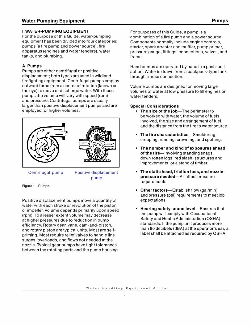
A. PumpsPumps are either centrifugal or positive displacement; both types are used in wildland firefighting equipment. Centrifugal pumps employ outward force from a center of rotation (known as the eye) to move or discharge water. With these pumps the volume will vary with speed (rpm) and pressure. Centrifugal pumps are usually larger than positive displacement pumps and are employed for higher volumes.
Centrifugal pump Positive displacement
pump
Figure 1—Pumps.
Positive displacement pumps move a quantity of water with each stroke or revolution of the piston or impeller. Volume depends primarily upon speed (rpm). To a lesser extent volume may decrease at higher pressures due to reduction in pump efficiency. Rotary gear, vane, cam-and-piston, and rotary piston are typical units. Most are self-priming. Most require relief valves to handle line surges, overloads, and flows not needed at the nozzle. Typical gear pumps have tight tolerances between the rotating parts and the pump housing.
For purposes of this Guide, a pump is a combination of a fire pump and a power source. Components normally include engine controls, starter, spark arrester and muffler, pump primer, pressure gauge, fittings, connections, valves, and frame.
Hand pumps are operated by hand in a push-pull action. Water is drawn from a backpack-type tank through a hose connection.
Volume pumps are designed for moving large volumes of water at low pressure to fill engines or water tenders.
Special Considerations• The size of the job—The perimeter to
be worked with water, the volume of fuels involved, the size and arrangement of fuel, and the distance from the fire to water source.
• The fire characteristics—Smoldering, creeping, running, crowning, and spotting.
• The number and kind of exposures ahead of the fire—Involving standing snags, down rotten logs, red slash, structures and improvements, or a stand of timber.
• The static head, friction loss, and nozzle pressure needed—All affect pressure requirements.
• Other factors—Establish flow (gal/min) and pressure (psi) requirements to meet job expectations.
• Hearing safety sound level—Ensures that the pump will comply with Occupational Safety and Health Administration (OSHA) standards. If the pump unit produces more than 90 decibels (dBA) at the operator’s ear, a label shall be attached as required by OSHA.
Pumps
S i x t h E d i t i o n
5
Water Pumping Equipment
Work AssignmentsThe typical assignments for a wildland fire pump are demanding and require rugged equipment. The following should be taken into consideration during the pump selection process:
• Flow (gal/min) requirements are highly variable; water conservation is important.
• Service is through lightweight, small-diameter hose lines, where friction loss is high.
• Hose lays are often long.
• Hose is often laid up steep slopes, with resulting high static head pressures.
• Water is normally under high suction lifts from source to pump.
• Engine power will be reduced as altitude increases.
• Temperatures are often high.
• Hours of work are long.
• Long service life is required.
• Weight is an extremely important factor, particularly with portable pumps.
• Available water is often abrasive and corrosive.
• Pump reliability is extremely important.
• Ease of operation and maintenance.
• Performance versus initial investment and repairs.
Pumps
This section covering pumps is not meant to be all inclusive. The pumps described herein are a representative sampling based on information received during the national input solicitation for the revision of this publication. They are not intended to be an endorsement of any product and may not meet some agency’s standards.
The lightweight portable and high pressure portable pumps shown are those currently available through the National Interagency Support Cache (NISC) system. The performance listed for these pumps is consistant with the pump performance found in the March 2012 edition of S-211, Portable Pumps and Water Use course.
W a t e r H a n d l i n g E q u i p m e n t G u i d e
6
Water Pumping Equipment
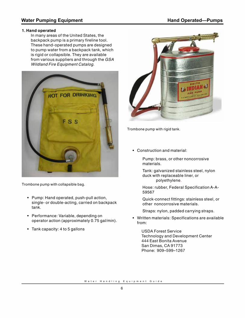
1. Hand operatedIn many areas of the United States, the backpack pump is a primary fireline tool. These hand-operated pumps are designed to pump water from a backpack tank, which is rigid or collapsible. They are available from various suppliers and through the GSA Wildland Fire Equipment Catalog.
Trombone pump with collapsible bag.
• Pump: Hand operated, push-pull action, single- or double-acting, carried on backpack tank.
• Performance: Variable, depending on operator action (approximately 0.75 gal/min).
• Tank capacity: 4 to 5 gallons
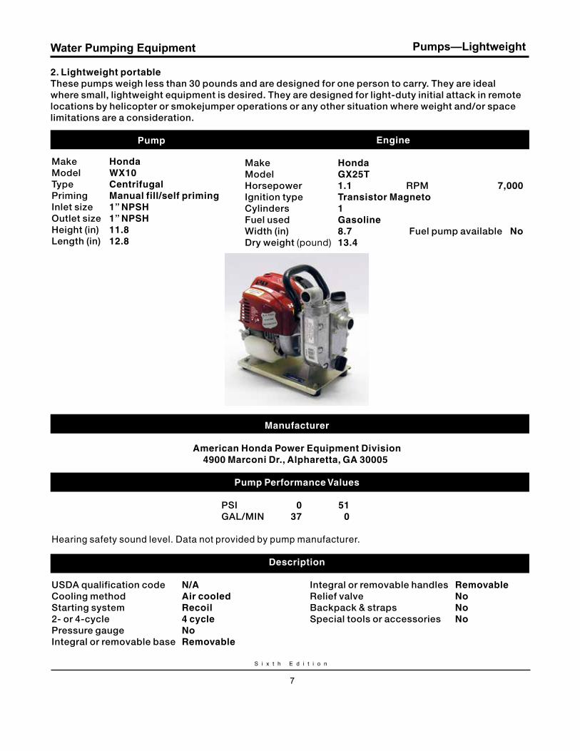
Trombone pump with rigid tank.
• Construction and material:
Pump: brass, or other noncorrosive materials.
Tank: galvanized stainless steel, nylon duck with replaceable liner, or polyethylene.
Hose: rubber, Federal Specification A-A- 59567
Quick-connect fittings: stainless steel, or other noncorrosive materials.
Straps: nylon, padded carrying straps.
• Written materials: Specifications are available from:
USDA Forest ServiceTechnology and Development Center444 East Bonita AvenueSan Dimas, CA 91773Phone: 909–599–1267
Hand Operated—Pumps
S i x t h E d i t i o n
7
Water Pumping Equipment Pumps—Lightweight
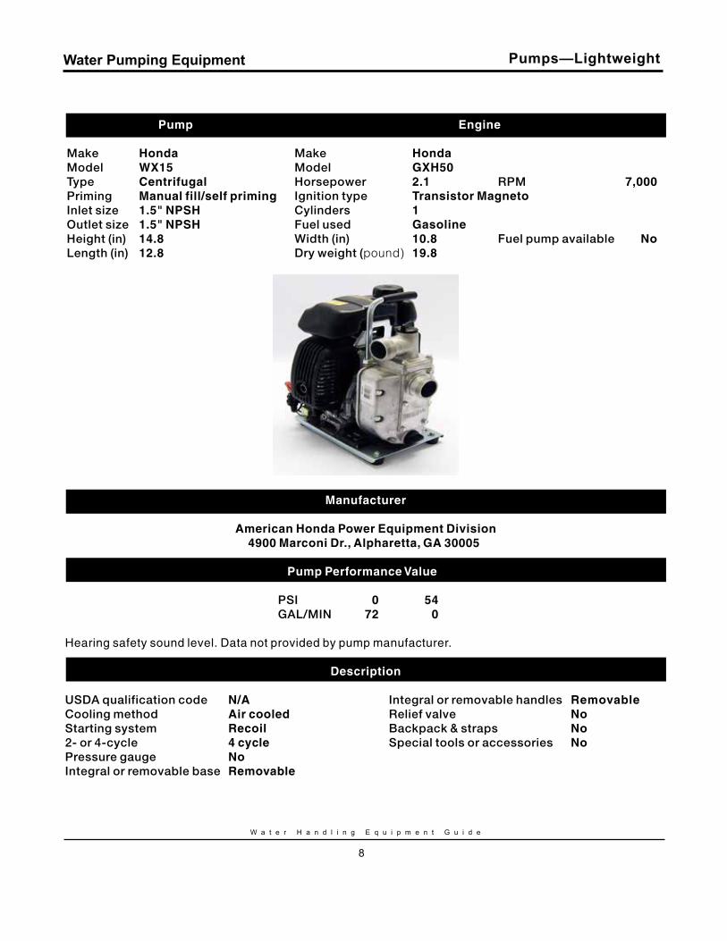
2. Lightweight portable These pumps weigh less than 30 pounds and are designed for one person to carry. They are ideal where small, lightweight equipment is desired. They are designed for light-duty initial attack in remote locations by helicopter or smokejumper operations or any other situation where weight and/or space limitations are a consideration.
Pump
Make Honda. Model Wx10. Type Centrifugal.Priming manual fill/self priming .Inlet size 1” NPSH. Outlet size 1” NPSH. Height (in) 11.8.Length (in) 12.8.
Engine
Make Honda. Model Gx25T. Horsepower 1.1. RPM 7,000.Ignition type Transistor magneto. Cylinders 1. Fuel used Gasoline Width (in) 8.7. .Fuel pump available No.Dry weight (pound) 13.4.
manufacturer
American Honda Power Equipment Division4900 marconi Dr., Alpharetta, GA 30005.
Pump Performance values
PSI 0 51. GAL/MIN 37 0.
Hearing safety sound level. Data not provided by pump manufacturer.
Description USDA qualification code N/A Integral or removable handles removableCooling method Air cooled Relief valve No Starting system recoil Backpack & straps No 2- or 4-cycle 4 cycle Special tools or accessories No Pressure gauge No Integral or removable base removable
W a t e r H a n d l i n g E q u i p m e n t G u i d e
8
Water Pumping Equipment
Pump
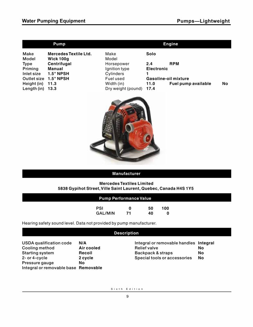
Make Honda..Model Wx15.Type Centrifugal.Priming manual fill/self priming.Inlet size 1.5" NPSH.Outlet size 1.5" NPSH.Height (in) 14.8.Length (in) 12.8.
Pumps—Lightweight
Engine
Make Honda.Model GxH50.Horsepower 2.1. RPM 7,000.Ignition type Transistor magneto.Cylinders 1.Fuel used GasolineWidth (in) 10.8.. Fuel pump available No.Dry weight (pound) 19.8.
manufacturer
American Honda Power Equipment Division4900 marconi Dr., Alpharetta, GA 30005.
Pump Performance values
PSI 0 54. GAL/MIN 72 0.
Hearing safety sound level. Data not provided by pump manufacturer.
Description USDA qualification code N/A. Integral or removable handles removable. Cooling method Air cooled. Relief valve No. Starting system recoil . Backpack & straps No. 2- or 4-cycle 4 cycle. Special tools or accessories No. Pressure gauge No.Integral or removable base removable.
S i x t h E d i t i o n
9
Water Pumping Equipment
Pump
Make mercedes Textile Ltd.Model Wick 100g.Type Centrifugal.Priming manual.Inlet size 1.5" NPSH.Outlet size 1.5" NPSH.Height (in) 11.3.Length (in) 13.3.
Pumps—Lightweight
Engine
Make Solo. Model. Horsepower 2.4. rPm.Ignition type Electronic. Cylinders 1.Fuel used Gasoline-oil mixture.Width (in) 11.0. Fuel pump available No.Dry weight (pound) 17.4.
manufacturer
mercedes Textiles Limited5838 Gypihot Street, ville Saint Laurent, quebec, Canada H4S 1y5.
Pump Performance values
PSI 0 50 100. GAL/MIN 71 40 0.
Hearing safety sound level. Data not provided by pump manufacturer.
Description USDA qualification code N/A. Integral or removable handles Integral.Cooling method Air cooled. Relief valve No. Starting system recoil . Backpack & straps No. 2- or 4-cycle 2 cycle. Special tools or accessories No. Pressure gauge No.Integral or removable base removable.
W a t e r H a n d l i n g E q u i p m e n t G u i d e
10
Water Pumping Equipment
Pump
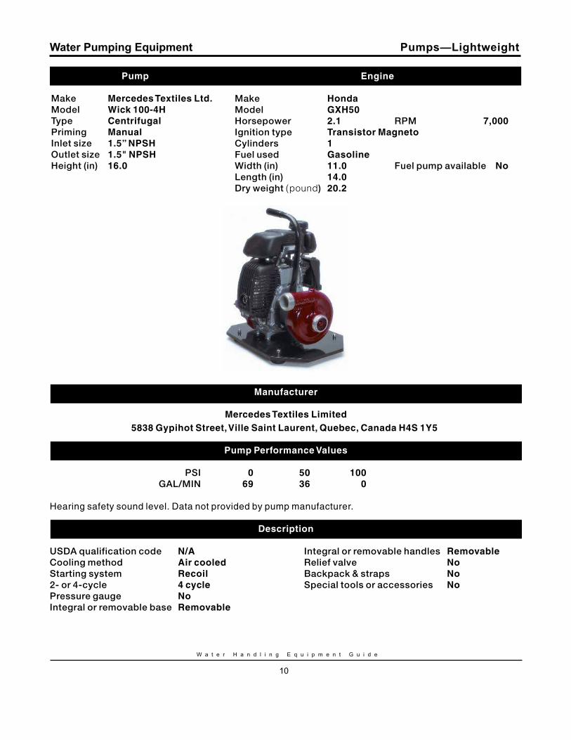
Make mercedes Textiles Ltd.Model Wick 100-4H.Type Centrifugal.Priming manual.Inlet size 1.5” NPSH.Outlet size 1.5" NPSH.Height (in) 16.0.
Pumps—Lightweight
Engine
Make Honda.Model GxH50.Horsepower 2.1. RPM 7,000.Ignition type Transistor magneto.Cylinders 1.Fuel used Gasoline.Width (in) 11.0. Fuel pump available No.Length (in) 14.0. Dry weight (pound) 20.2.
manufacturer
mercedes Textiles Limited5838 Gypihot Street, ville Saint Laurent, quebec, Canada H4S 1y5.
Pump Performance values
PSI 0 50 100. GAL/MIN 69 36 0.
Hearing safety sound level. Data not provided by pump manufacturer.
Description USDA qualification code N/A. Integral or removable handles removable. Cooling method Air cooled. Relief valve No. Starting system recoil . Backpack & straps No. 2- or 4-cycle 4 cycle. Special tools or accessories No. Pressure gauge No.Integral or removable base removable.
S i x t h E d i t i o n
11
Water Pumping Equipment
Pump
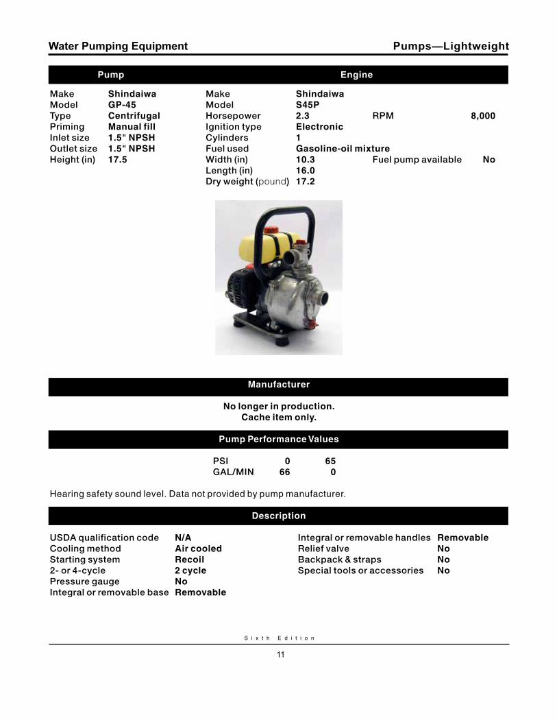
Make Shindaiwa.Model GP-45.Type Centrifugal.Priming manual fill.Inlet size 1.5" NPSH.Outlet size 1.5" NPSH.Height (in) 17.5.
Pumps—Lightweight
Engine
Make Shindaiwa.Model S45P.Horsepower 2.3. RPM 8,000.Ignition type Electronic.Cylinders 1.Fuel used Gasoline-oil mixture.Width (in) 10.3. Fuel pump available No.Length (in) 16.0. Dry weight (pound) 17.2.
manufacturer
No longer in production.Cache item only.
Pump Performance values
PSI 0 65. GAL/MIN 66 0.
Hearing safety sound level. Data not provided by pump manufacturer.
Description USDA qualification code N/A. Integral or removable handles removable.Cooling method Air cooled. Relief valve No. Starting system recoil . Backpack & straps No. 2- or 4-cycle 2 cycle. Special tools or accessories No. Pressure gauge No.Integral or removable base removable.
W a t e r H a n d l i n g E q u i p m e n t G u i d e
12
Water Pumping Equipment
Pump
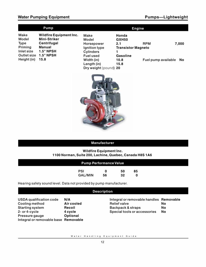
Make Wildfire Equipment Inc.Model mini-Striker.Type Centrifugal.Priming manual.Inlet size 1.5" NPSH.Outlet size 1.5" NPSH.Height (in) 15.8.
Pumps—Lightweight
Engine
Make Honda.Model GxH50.Horsepower 2.1. RPM 7,000.Ignition type Transistor magneto.Cylinders 1.Fuel used Gasoline.Width (in) 10.8. Fuel pump available No.Length (in) 15.8. Dry weight (pound) 20.
manufacturer
Wildfire Equipment Inc.1100 Norman, Suite 200, Lachine, quebec, Canada H8S 1A6.
Pump Performance value
PSI 0 50 85.GAL/MIN 56 32 0.
Hearing safety sound level. Data not provided by pump manufacturer.
Description USDA qualification code N/A. Integral or removable handles removable.Cooling method Air cooled. Relief valve No. Starting system recoil . Backpack & straps No. 2- or 4-cycle 4 cycle. Special tools or accessories No. Pressure gauge Optional. Integral or removable base removable.
S i x t h E d i t i o n
13
Water Pumping Equipment
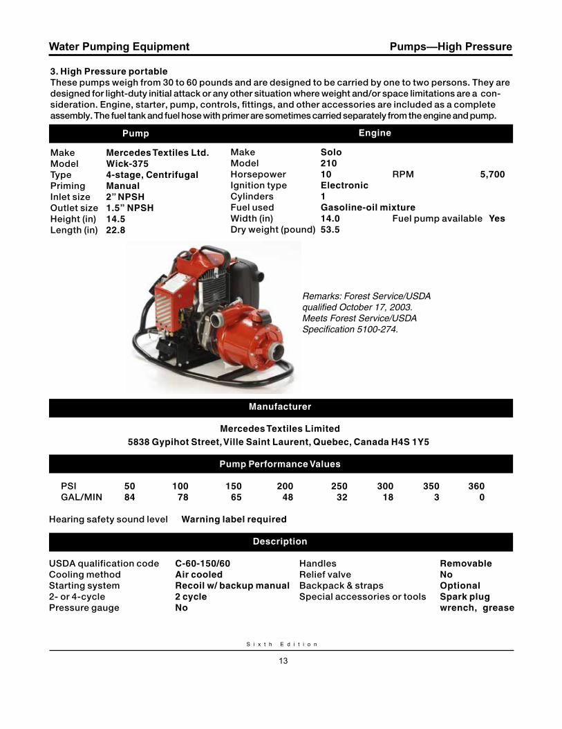
3. High Pressure portableThese pumps weigh from 30 to 60 pounds and are designed to be carried by one to two persons. They are designed for light-duty initial attack or any other situation where weight and/or space limitations are a con-sideration. Engine, starter, pump, controls, fittings, and other accessories are included as a complete assembly. The fuel tank and fuel hose with primer are sometimes carried separately from the engine and pump.
Pumps—High Pressure
Pump
Make mercedes Textiles Ltd.Model Wick-375.Type 4-stage, Centrifugal.Priming manual.Inlet size 2” NPSH.Outlet size 1.5” NPSH.Height (in) 14.5.Length (in) 22.8.
Engine
Make Solo.Model 210.Horsepower 10. RPM 5,700.Ignition type Electronic.Cylinders 1.Fuel used Gasoline-oil mixture .Width (in) 14.0. Fuel pump available yes.Dry weight (pound) 53.5.
Remarks: Forest Service/USDA qualified October 17, 2003.Meets Forest Service/USDA Specification 5100-274.
manufacturer
mercedes Textiles Limited5838 Gypihot Street, ville Saint Laurent, quebec, Canada H4S 1y5.
Pump Performance values
PSI 50 100 150 200 250 300 350 360. GAL/MIN 84 78 65 48 32 18 3 0.
Hearing safety sound level. Warning label required.
Description USDA qualification code C-60-150/60. Handles removable. Cooling method Air cooled. Relief valve No. Starting system recoil w/ backup manual. Backpack & straps Optional. 2- or 4-cycle 2 cycle. Special accessories or tools Spark plugPressure gauge No. wrench, grease

W a t e r H a n d l i n g E q u i p m e n t G u i d e
14
Water Pumping Equipment
Pump
Make Wildfire Equipment Inc.Model mark 3Type 4-stage, centrifugalPriming manualInlet size 2” NPSHOutlet size 1.5” NPSHHeight (in) 16.3Length (in) 23.0
Pumps—High Pressure
Engine
Make rotaxModel 185 ccHorsepower 10 RPM 5,000Ignition type magnetoCylinders 1Fuel used Gasoline-oil mixtureWidth (in) 12.0 Fuel pump available NoDry weight (pound) 55
Remarks: Forest Service/USDA qualified July 25, 2001.Meets Forest Service/USDA Specification 5100-274.
manufacturer
Wildfire Equipment Inc.1100 Norman, Suite 200, Lachine, quebec, Canada H8S 1A6
Pump Performance values PSI 50 100 150 200 250 300 350 380 GAL/MIN 89 78 65 52 38 25 9 0
Hearing safety sound level Warning label required
Description
USDA qualification code C-60-150/50 Integral or removable handles No Cooling method Air cooled Relief valve No Starting system recoil w/ backup manual Backpack & straps Optional 2- or 4-cycle 2 cycle Special accessories or tools Spark plug Pressure gauge No wrench, grease Integral or removable base No gun included
S i x t h E d i t i o n
15
Water Pumping Equipment Pumps—Floatable
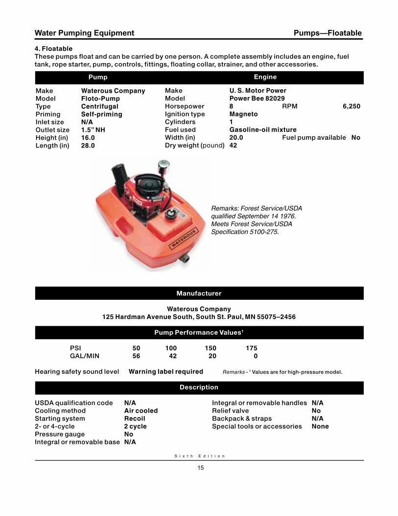
4. FloatableThese pumps float and can be carried by one person. A complete assembly includes an engine, fuel tank, rope starter, pump, controls, fittings, floating collar, strainer, and other accessories.
Pump
Make Waterous CompanyModel Floto-PumpType CentrifugalPriming Self-primingInlet size N/AOutlet size 1.5” NH Height (in) 16.0Length (in) 28.0
Engine
Make u. S. motor PowerModel Power Bee 82029Horsepower 8 RPM 6,250Ignition type magneto Cylinders 1Fuel used Gasoline-oil mixtureWidth (in) 20.0 Fuel pump available NoDry weight (pound) 42
Remarks: Forest Service/USDA qualified September 14 1976.Meets Forest Service/USDA Specification 5100-275.
Manufacturer
Waterous Company125 Hardman Avenue South, South St. Paul, mN 55075–2456
Pump Performance Values1
PSI 50 100 150 175 GAL/MIN 56 42 20 0
Hearing safety sound level Warning label required Remarks - 1 Values are for high-pressure model.
Description USDA qualification code N/A Integral or removable handles N/A Cooling method Air cooled Relief valve No Starting system recoil Backpack & straps N/A 2- or 4-cycle 2 cycle Special tools or accessories None Pressure gauge No Integral or removable base N/A
W a t e r H a n d l i n g E q u i p m e n t G u i d e
16
Water Pumping Equipment
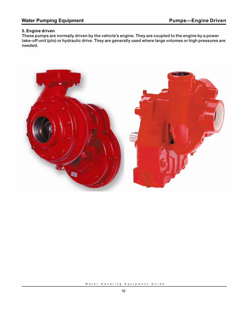
5. Engine drivenThese pumps are normally driven by the vehicle’s engine. They are coupled to the engine by a power take-off unit (pto) or hydraulic drive. They are generally used where large volumes or high pressures are needed.
Pumps—Engine Driven
S i x t h E d i t i o n
17
Water Pumping Equipment Fire Apparatus
1. All types shall meet federal, state and agency requirements for motor vehicle safety standards, including all gross vehicle weight ratings when fully loaded.
2. Type 3 engines and tactical water tenders shall be equipped with a foam proportioner system.
3. All water tenders and engine types 3 through 6 shall be able to prime and pump water from a 10 foot lift.
4. Personnel shall meet the qualification requirements of NWCG Wildland Fire Qualification System Guide, PMS 310-1.
Common Additional Needs – request as Needed• All Wheel Drive (includes four wheel drive)• High pressure pump (250 psi at one half flow of Type) —NFPA 1901 compliant Type 1 and 2 engines will produce one half of rated flow at 250 psi. Type 3 engines are already required to produce rated flow (150 gpm) at 250 psi. If Types 4 through 6 are ordered as high pressure it is recommended that they be required to produce rated flow at 250 psi (50 gpm).• Foam Proportioner• Compressed Air Foam System (CAFS) 40 cfm minimum• Additional Personnel
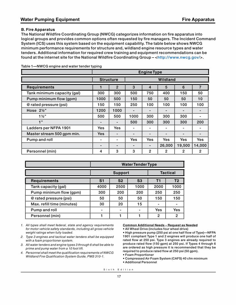
B. Fire ApparatusThe National Wildfire Coordinating Group (NWCG) categorizes information on fire apparatus into logical groups and provides common options often requested by fire managers. The Incident Command System (ICS) uses this system based on the equipment capability. The table below shows NWCG minimum performance requirements for structure and, wildland engine resource types and water tenders. Additional information for required crew training and equipment recommendations can be found at the internet site for the National Wildfire Coordinating Group – <http://www.nwcg.gov/>.
Table 1—NWCG engine and water tender typing
Engine Type
Structure Wildland
requirements 1 2 3 4 5 6 7
Tank minimum capacity (gal) 300 300 500 750 400 150 50
Pump minimum flow (gpm) 1000 500 150 50 50 50 10
@ rated pressure (psi) 150 150 250 100 100 100 100
Hose 2½” 1200 1000 - - - - -
1½” 500 500 1000 300 300 300 -
1” - - 500 300 300 300 200
Ladders per NFPA 1901 Yes Yes - - - - -
Master stream 500 gpm min. Yes - - - - - -
Pump and roll - - Yes Yes Yes Yes Yes
- - - - 26,000 19,500 14,000
Personnel (min) 4 3 3 2 2 2 2
Water Tender Type
Support Tactical
requirements S1 S2 S3 T1 T2
Tank capacity (gal) 4000 2500 1000 2000 1000
Pump minimum flow (gpm) 300 200 200 250 250
@ rated pressure (psi) 50 50 50 150 150
Max. refill time (minutes) 30 20 15 - -
Pump and roll - - - Yes Yes
Personnel (min) 1 1 1 2 2
W a t e r H a n d l i n g E q u i p m e n t G u i d e
18
Water Pumping Equipment Fire Apparatus
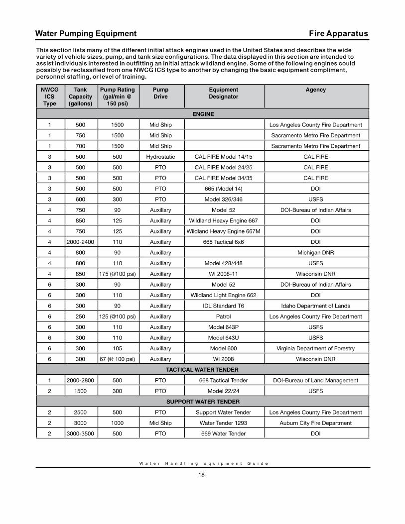
This section lists many of the different initial attack engines used in the United States and describes the wide variety of vehicle sizes, pump, and tank size configurations. The data displayed in this section are intended to assist individuals interested in outfitting an initial attack wildland engine. Some of the following engines could possibly be reclassified from one NWCG ICS type to another by changing the basic equipment compliment, personnel staffing, or level of training.
NWCG ICS
Type
Tank Capacity (gallons)
Pump rating (gal/min @
150 psi)
Pump Drive
EquipmentDesignator
Agency
ENGINE
1 500 1500 Mid Ship Los Angeles County Fire Department
1 750 1500 Mid Ship Sacramento Metro Fire Department
1 700 1500 Mid Ship Sacramento Metro Fire Department
3 500 500 Hydrostatic CAL FIRE Model 14/15 CAL FIRE
3 500 500 PTO CAL FIRE Model 24/25 CAL FIRE
3 500 500 PTO CAL FIRE Model 34/35 CAL FIRE
3 500 500 PTO 665 (Model 14) DOI
3 600 300 PTO Model 326/346 USFS
4 750 90 Auxillary Model 52 DOI-Bureau of Indian Affairs
4 850 125 Auxillary Wildland Heavy Engine 667 DOI
4 750 125 Auxillary Wildland Heavy Engine 667M DOI
4 2000-2400 110 Auxillary 668 Tactical 6x6 DOI
4 800 90 Auxillary Michigan DNR
4 800 110 Auxillary Model 428/448 USFS
4 850 175 (@100 psi) Auxillary WI 2008-11 Wisconsin DNR
6 300 90 Auxillary Model 52 DOI-Bureau of Indian Affairs
6 300 110 Auxillary Wildland Light Engine 662 DOI
6 300 90 Auxillary IDL Standard T6 Idaho Department of Lands
6 250 125 (@100 psi) Auxillary Patrol Los Angeles County Fire Department
6 300 110 Auxillary Model 643P USFS
6 300 110 Auxillary Model 643U USFS
6 300 105 Auxillary Model 600 Virginia Department of Forestry
6 300 67 (@ 100 psi) Auxillary WI 2008 Wisconsin DNR
TACTICAL WATEr TENDEr
1 2000-2800 500 PTO 668 Tactical Tender DOI-Bureau of Land Management
2 1500 300 PTO Model 22/24 USFS
SUPPORT WATER TENDER
2 2500 500 PTO Support Water Tender Los Angeles County Fire Department
2 3000 1000 Mid Ship Water Tender 1293 Auburn City Fire Department
2 3000-3500 500 PTO 669 Water Tender DOI
S i x t h E d i t i o n
19
Water Pumping Equipment
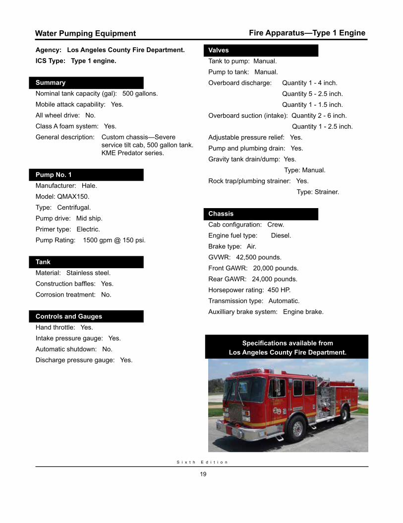
Agency: Los Angeles County Fire Department.ICS Type: Type 1 engine.
Summary.Nominal tank capacity (gal): 500 gallons.Mobile attack capability: Yes.All wheel drive: No.Class A foam system: Yes.General description: Custom chassis—Severe
service tilt cab, 500 gallon tank. KME Predator series.
Pump No. 1.Manufacturer: Hale. Model: QMAX150.Type: Centrifugal. Pump drive: Mid ship.Primer type: Electric.Pump Rating: 1500 gpm @ 150 psi.
Tank.Material: Stainless steel.Construction baffles: Yes.Corrosion treatment: No.
Controls and Gauges.Hand throttle: Yes.Intake pressure gauge: Yes.Automatic shutdown: No.Discharge pressure gauge: Yes.
Valves.Tank to pump: Manual.Pump to tank: Manual.Overboard discharge: Quantity 1 - 4 inch. Quantity 5 - 2.5 inch. Quantity 1 - 1.5 inch.Overboard suction (intake): Quantity 2 - 6 inch. Quantity 1 - 2.5 inch.Adjustable pressure relief: Yes.Pump and plumbing drain: Yes.Gravity tank drain/dump: Yes. Type: Manual.Rock trap/plumbing strainer: Yes. Type: Strainer.
Chassis.Cab configuration: Crew.Engine fuel type: Diesel.Brake type: Air. GVWR: 42,500 pounds. Front GAWR: 20,000 pounds.Rear GAWR: 24,000 pounds.Horsepower rating: 450 HP.Transmission type: Automatic.Auxilliary brake system: Engine brake.
Specifications available from Los Angeles County Fire Department.
Fire Apparatus—Type 1 Engine
W a t e r H a n d l i n g E q u i p m e n t G u i d e
20
Water Pumping Equipment
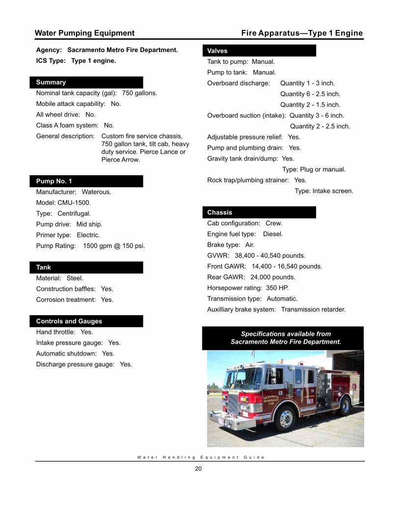
Agency: Sacramento Metro Fire Department.ICS Type: Type 1 engine.
Summary.Nominal tank capacity (gal): 750 gallons.Mobile attack capability: No.All wheel drive: No.Class A foam system: No.General description: Custom fire service chassis,
750 gallon tank, tilt cab, heavy duty service. Pierce Lance or Pierce Arrow.
Pump No. 1.Manufacturer: Waterous. Model: CMU-1500.Type: Centrifugal. Pump drive: Mid ship.Primer type: Electric.Pump Rating: 1500 gpm @ 150 psi.
Tank.Material: Steel.Construction baffles: Yes.Corrosion treatment: Yes.
Controls and Gauges.Hand throttle: Yes.Intake pressure gauge: Yes.Automatic shutdown: Yes.Discharge pressure gauge: Yes.
Valves.Tank to pump: Manual.Pump to tank: Manual.Overboard discharge: Quantity 1 - 3 inch. Quantity 6 - 2.5 inch. Quantity 2 - 1.5 inch.Overboard suction (intake): Quantity 3 - 6 inch. Quantity 2 - 2.5 inch.Adjustable pressure relief: Yes.Pump and plumbing drain: Yes.Gravity tank drain/dump: Yes. Type: Plug or manual.Rock trap/plumbing strainer: Yes. Type: Intake screen.
Chassis.Cab configuration: Crew.Engine fuel type: Diesel.Brake type: Air. GVWR: 38,400 - 40,540 pounds. Front GAWR: 14,400 - 16,540 pounds.Rear GAWR: 24,000 pounds.Horsepower rating: 350 HP.Transmission type: Automatic.Auxilliary brake system: Transmission retarder.
Specifications available from Sacramento Metro Fire Department.
Fire Apparatus—Type 1 Engine
S i x t h E d i t i o n
21
Water Pumping Equipment
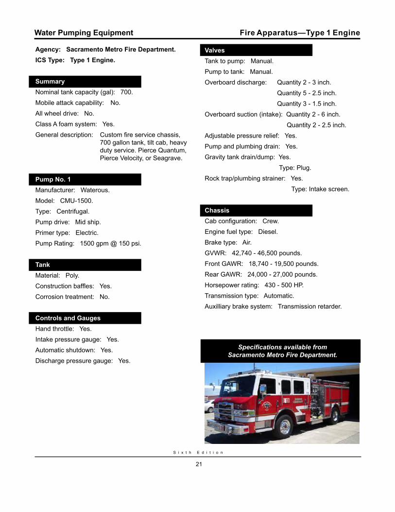
Agency: Sacramento Metro Fire Department.ICS Type: Type 1 Engine.
Summary.Nominal tank capacity (gal): 700.Mobile attack capability: No.All wheel drive: No.Class A foam system: Yes.General description: Custom fire service chassis,
700 gallon tank, tilt cab, heavy duty service. Pierce Quantum, Pierce Velocity, or Seagrave.
Pump No. 1.Manufacturer: Waterous. Model: CMU-1500.Type: Centrifugal.Pump drive: Mid ship.Primer type: Electric.Pump Rating: 1500 gpm @ 150 psi.
Tank.Material: Poly.Construction baffles: Yes.Corrosion treatment: No.
Controls and Gauges..Hand throttle: Yes.Intake pressure gauge: Yes.Automatic shutdown: Yes.Discharge pressure gauge: Yes.
Valves.Tank to pump: Manual.Pump to tank: Manual.Overboard discharge: Quantity 2 - 3 inch. Quantity 5 - 2.5 inch. Quantity 3 - 1.5 inch.Overboard suction (intake): Quantity 2 - 6 inch. Quantity 2 - 2.5 inch.Adjustable pressure relief: Yes.Pump and plumbing drain: Yes.Gravity tank drain/dump: Yes. Type: Plug.Rock trap/plumbing strainer: Yes. Type: Intake screen.
Chassis.Cab configuration: Crew.Engine fuel type: Diesel. Brake type: Air.GVWR: 42,740 - 46,500 pounds. Front GAWR: 18,740 - 19,500 pounds.Rear GAWR: 24,000 - 27,000 pounds.Horsepower rating: 430 - 500 HP.Transmission type: Automatic.Auxilliary brake system: Transmission retarder.
Specifications available from Sacramento Metro Fire Department.
Fire Apparatus—Type 1 Engine
W a t e r H a n d l i n g E q u i p m e n t G u i d e
22
Water Pumping Equipment
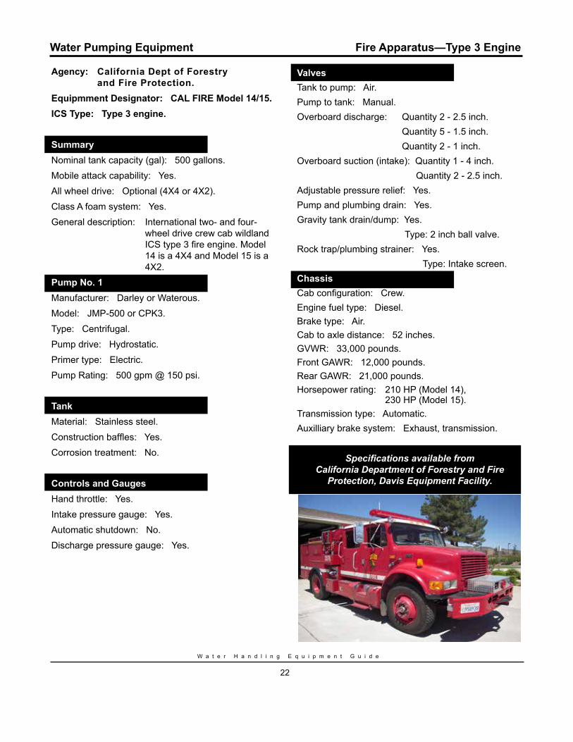
Agency: California Dept of Forestry and Fire Protection.Equipmment Designator: CAL FIRE Model 14/15.ICS Type: Type 3 engine.
Summary.Nominal tank capacity (gal): 500 gallons.Mobile attack capability: Yes.All wheel drive: Optional (4X4 or 4X2).Class A foam system: Yes.General description: International two- and four-
wheel drive crew cab wildland ICS type 3 fire engine. Model 14 is a 4X4 and Model 15 is a 4X2.
Pump No. 1.Manufacturer: Darley or Waterous. Model: JMP-500 or CPK3.Type: Centrifugal.Pump drive: Hydrostatic.Primer type: Electric.Pump Rating: 500 gpm @ 150 psi.
Tank.Material: Stainless steel.Construction baffles: Yes.Corrosion treatment: No.
Controls and Gauges.Hand throttle: Yes.Intake pressure gauge: Yes.Automatic shutdown: No.Discharge pressure gauge: Yes.
Fire Apparatus—Type 3 Engine
Valves.Tank to pump: Air.Pump to tank: Manual.Overboard discharge: Quantity 2 - 2.5 inch. Quantity 5 - 1.5 inch. Quantity 2 - 1 inch.Overboard suction (intake): Quantity 1 - 4 inch. Quantity 2 - 2.5 inch.Adjustable pressure relief: Yes.Pump and plumbing drain: Yes.Gravity tank drain/dump: Yes. Type: 2 inch ball valve.Rock trap/plumbing strainer: Yes. Type: Intake screen.Chassis.Cab configuration: Crew.Engine fuel type: Diesel.Brake type: Air.Cab to axle distance: 52 inches.GVWR: 33,000 pounds.Front GAWR: 12,000 pounds.Rear GAWR: 21,000 pounds.Horsepower rating: 210 HP (Model 14), 230 HP (Model 15).Transmission type: Automatic.Auxilliary brake system: Exhaust, transmission.
Specifications available from California Department of Forestry and Fire
Protection, Davis Equipment Facility.
S i x t h E d i t i o n
23
Water Pumping Equipment
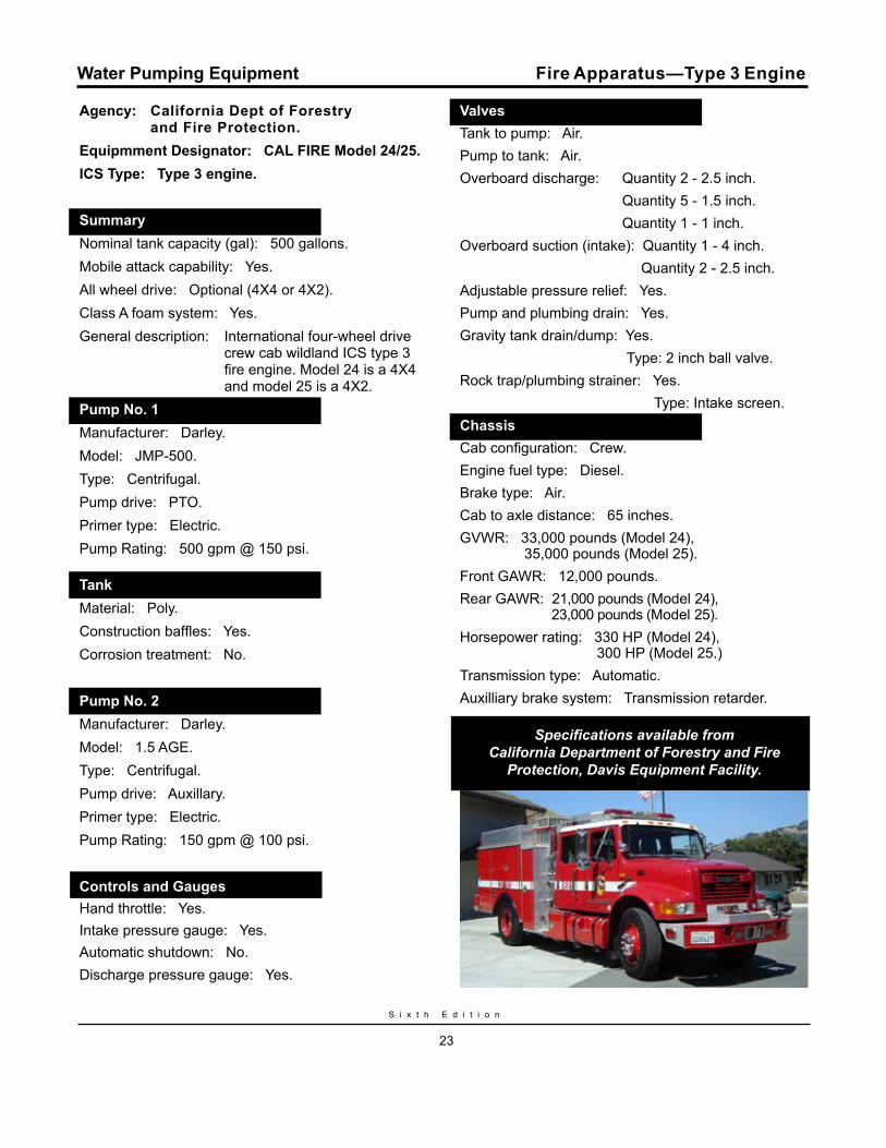
Agency: California Dept of Forestry and Fire Protection.Equipmment Designator: CAL FIRE Model 24/25.ICS Type: Type 3 engine.
Summary.Nominal tank capacity (gal): 500 gallons.Mobile attack capability: Yes.All wheel drive: Optional (4X4 or 4X2).Class A foam system: Yes.General description: International four-wheel drive
crew cab wildland ICS type 3 fire engine. Model 24 is a 4X4 and model 25 is a 4X2.
Pump No. 1.Manufacturer: Darley. Model: JMP-500.Type: Centrifugal.Pump drive: PTO.Primer type: Electric.Pump Rating: 500 gpm @ 150 psi.
Tank.Material: Poly.Construction baffles: Yes.Corrosion treatment: No.
Pump No. 2.Manufacturer: Darley. Model: 1.5 AGE.Type: Centrifugal.Pump drive: Auxillary.Primer type: Electric.Pump Rating: 150 gpm @ 100 psi.
Controls and Gauges.Hand throttle: Yes.Intake pressure gauge: Yes.Automatic shutdown: No.Discharge pressure gauge: Yes.
Fire Apparatus—Type 3 Engine
Valves.Tank to pump: Air.Pump to tank: Air.Overboard discharge: Quantity 2 - 2.5 inch. Quantity 5 - 1.5 inch. Quantity 1 - 1 inch.Overboard suction (intake): Quantity 1 - 4 inch. Quantity 2 - 2.5 inch.Adjustable pressure relief: Yes.Pump and plumbing drain: Yes.Gravity tank drain/dump: Yes. Type: 2 inch ball valve.Rock trap/plumbing strainer: Yes. Type: Intake screen.Chassis.Cab configuration: Crew.Engine fuel type: Diesel.Brake type: Air.Cab to axle distance: 65 inches.GVWR: 33,000 pounds (Model 24), 35,000 pounds (Model 25).Front GAWR: 12,000 pounds.Rear GAWR: 21,000 pounds (Model 24), 23,000 pounds (Model 25).Horsepower rating: 330 HP (Model 24), 300 HP (Model 25.)Transmission type: Automatic.Auxilliary brake system: Transmission retarder.
Specifications available from California Department of Forestry and Fire
Protection, Davis Equipment Facility.
W a t e r H a n d l i n g E q u i p m e n t G u i d e
24
Water Pumping Equipment
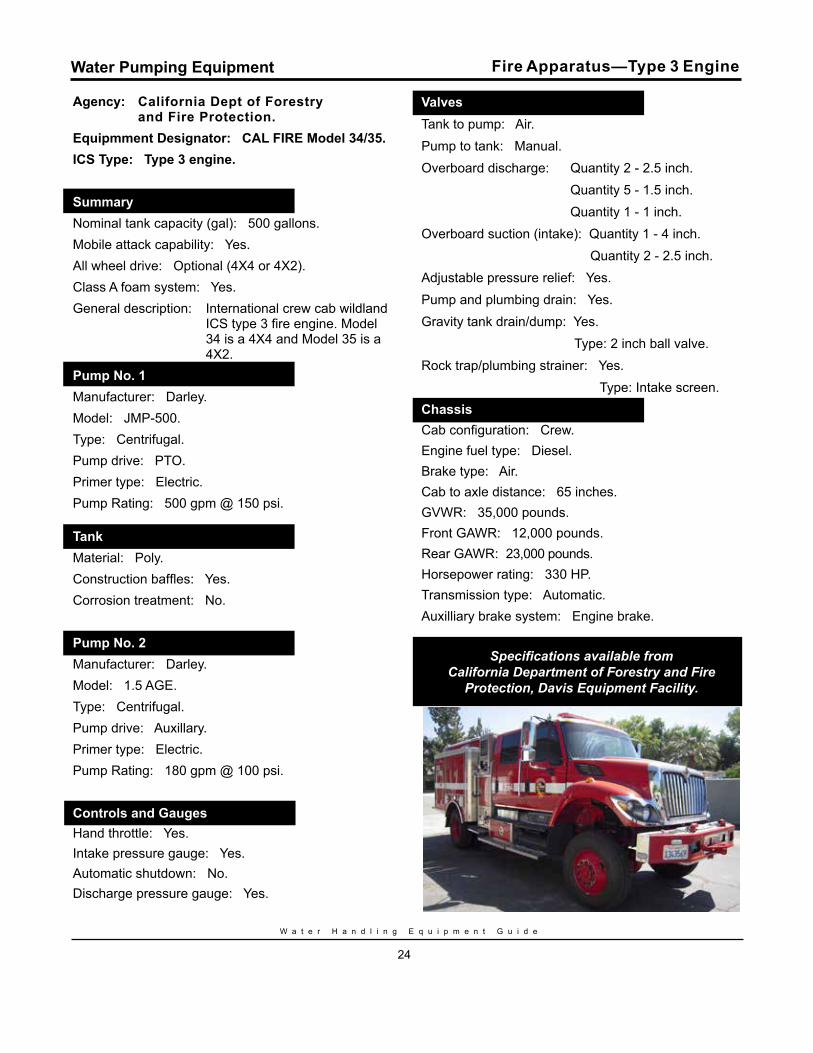
Agency: California Dept of Forestry and Fire Protection.Equipmment Designator: CAL FIRE Model 34/35.ICS Type: Type 3 engine.
Summary.Nominal tank capacity (gal): 500 gallons.Mobile attack capability: Yes.All wheel drive: Optional (4X4 or 4X2).Class A foam system: Yes.General description: International crew cab wildland
ICS type 3 fire engine. Model 34 is a 4X4 and Model 35 is a 4X2.
Pump No. 1.Manufacturer: Darley. Model: JMP-500.Type: Centrifugal.Pump drive: PTO.Primer type: Electric.Pump Rating: 500 gpm @ 150 psi.
Tank.Material: Poly.Construction baffles: Yes.Corrosion treatment: No.
Pump No. 2.Manufacturer: Darley. Model: 1.5 AGE.Type: Centrifugal.Pump drive: Auxillary.Primer type: Electric.Pump Rating: 180 gpm @ 100 psi.
Controls and Gauges.Hand throttle: Yes.Intake pressure gauge: Yes.Automatic shutdown: No.Discharge pressure gauge: Yes.
Fire Apparatus—Type 3 Engine
Valves.Tank to pump: Air.Pump to tank: Manual.Overboard discharge: Quantity 2 - 2.5 inch. Quantity 5 - 1.5 inch. Quantity 1 - 1 inch.Overboard suction (intake): Quantity 1 - 4 inch. Quantity 2 - 2.5 inch.Adjustable pressure relief: Yes.Pump and plumbing drain: Yes.Gravity tank drain/dump: Yes. Type: 2 inch ball valve.Rock trap/plumbing strainer: Yes. Type: Intake screen.Chassis.Cab configuration: Crew.Engine fuel type: Diesel.Brake type: Air.Cab to axle distance: 65 inches.GVWR: 35,000 pounds.Front GAWR: 12,000 pounds.Rear GAWR: 23,000 pounds.Horsepower rating: 330 HP.Transmission type: Automatic.Auxilliary brake system: Engine brake.
Specifications available from California Department of Forestry and Fire
Protection, Davis Equipment Facility.

S i x t h E d i t i o n
25
Water Pumping Equipment
Agency: Department of the Interior. Equipmment Designator: 665 Interface engine (Model 14).ICS Type: Type 3 engine.
Summary.Nominal tank capacity (gal): 500 gallons.Mobile attack capability: Yes.All wheel drive: Yes.Class A foam system: Yes.General description: This is a standard engine
with DOI for the Bureau of Land Management, National Park Service, Bureau of Indian Affairs, and the U.S. Fish and Wildlife Service. Color and striping will vary agency to agency.
Pump No. 1.Manufacturer: Darley. Model: JMP-500.Type: Centrifugal.Pump drive: PTO.Primer type: Electric.Pump Rating: 500 gpm @ 150 psi.
Tank.Material: Poly.Construction baffles: Yes.Corrosion treatment: No.Pump No. 2.Manufacturer: Darley. Model: 1.5 AGE.Type: Centrifugal.Pump drive: Auxillary.Primer type: Electric.Pump Rating: 120 gpm @ 150 psi. Controls and Gauges.Hand throttle: Yes.Intake pressure gauge: Yes.Automatic shutdown: Yes.Discharge pressure gauge: Yes.
Fire Apparatus—Type 3 Engine
Valves.Tank to pump: Electric.Pump to tank: Manual.Overboard discharge: Quantity 2 - 2.5 inch. Quantity 3 - 1.5 inch. Quantity 1 - 1 inch.Overboard suction (intake): Quantity 2 - 4 inch. Quantity 1 - 3 inch.Adjustable pressure relief: Yes.Pump and plumbing drain: Yes.Gravity tank drain/dump: No.Rock trap/plumbing strainer: No.
Chassis.Cab configuration: Crew.Engine fuel type: Diesel.Brake type: Air.Cab to axle distance: 62 inches.GVWR: 33,000 pounds.Front GAWR: 12,000 pounds.Rear GAWR: 23,000 pounds.Horsepower rating: 300 HP.Transmission type: Automatic.Auxilliary brake system: Exhaust.
Specifications available from National Fire Equipment Program, BLM,
National Interagency Fire Center.
W a t e r H a n d l i n g E q u i p m e n t G u i d e
26
Water Pumping Equipment
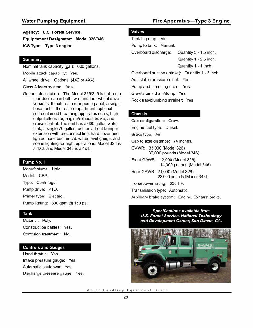
Agency: U.S. Forest Service. Equipmment Designator: Model 326/346.ICS Type: Type 3 engine.
Summary.Nominal tank capacity (gal): 600 gallons.Mobile attack capability: Yes.All wheel drive: Optional (4X2 or 4X4).Class A foam system: Yes.General description: The Model 326/346 is built on a
four-door cab in both two- and four-wheel drive versions. It features a rear pump panel, a single hose reel in the rear compartment, optional self-contained breathing apparatus seats, high output alternator, engine/exhaust brake, and cruise control. The unit has a 600 gallon water tank, a single 70 gallon fuel tank, front bumper extension with preconnect line, hard cover and lighted hose bed, in-cab water level gauge, and scene lighting for night operations. Model 326 is a 4X2, and Model 346 is a 4x4.
Pump No. 1.Manufacturer: Hale. Model: CBP.Type: Centrifugal.Pump drive: PTO.Primer type: Electric.Pump Rating: 300 gpm @ 150 psi.
Tank.Material: Poly.Construction baffles: Yes.Corrosion treatment: No.
Controls and Gauges.Hand throttle: Yes.Intake pressure gauge: Yes.Automatic shutdown: Yes.Discharge pressure gauge: Yes.
Fire Apparatus—Type 3 Engine
Valves.Tank to pump: Air.Pump to tank: Manual.Overboard discharge: Quantity 5 - 1.5 inch. Quantity 1 - 2.5 inch. Quantity 1 - 1 inch.Overboard suction (intake): Quantity 1 - 3 inch.Adjustable pressure relief: Yes.Pump and plumbing drain: Yes.Gravity tank drain/dump: Yes.Rock trap/plumbing strainer: Yes.
Chassis.Cab configuration: Crew.Engine fuel type: Diesel.Brake type: Air.Cab to axle distance: 74 inches.GVWR: 33,000 (Model 326); 37,000 pounds (Model 346).Front GAWR: 12,000 (Model 326); 14,000 pounds (Model 346).Rear GAWR: 21,000 (Model 326); 23,000 pounds (Model 346).Horsepower rating: 330 HP.Transmission type: Automatic.Auxilliary brake system: Engine, Exhaust brake.
Specifications available from U.S. Forest Service, National Technology and Development Center, San Dimas, CA.
S i x t h E d i t i o n
27
Water Pumping Equipment
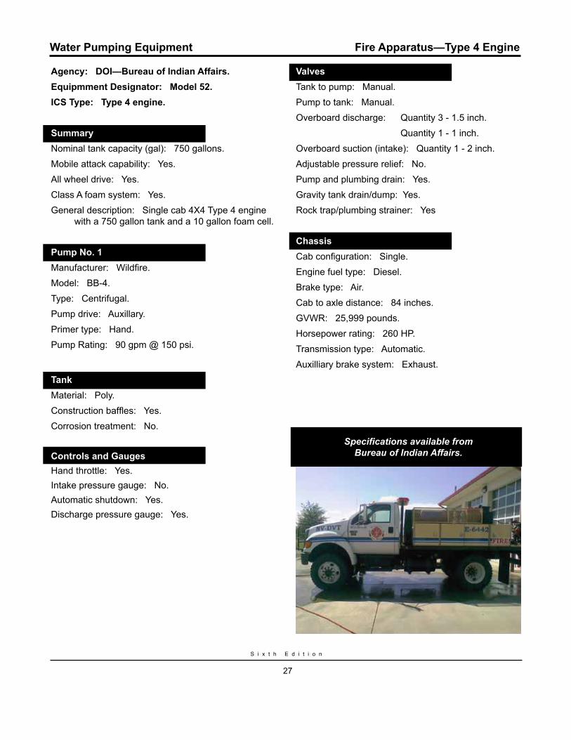
Agency: DOI—Bureau of Indian Affairs. Equipmment Designator: Model 52.ICS Type: Type 4 engine.
Summary.Nominal tank capacity (gal): 750 gallons.Mobile attack capability: Yes.All wheel drive: Yes.Class A foam system: Yes.General description: Single cab 4X4 Type 4 engine
with a 750 gallon tank and a 10 gallon foam cell.
Pump No. 1.Manufacturer: Wildfire. Model: BB-4.Type: Centrifugal.Pump drive: Auxillary.Primer type: Hand.Pump Rating: 90 gpm @ 150 psi.
Tank.Material: Poly.Construction baffles: Yes.Corrosion treatment: No.
Controls and Gauges.Hand throttle: Yes.Intake pressure gauge: No.Automatic shutdown: Yes.Discharge pressure gauge: Yes.
Fire Apparatus—Type 4 Engine
Valves.Tank to pump: Manual.Pump to tank: Manual.Overboard discharge: Quantity 3 - 1.5 inch. Quantity 1 - 1 inch.Overboard suction (intake): Quantity 1 - 2 inch.Adjustable pressure relief: No.Pump and plumbing drain: Yes.Gravity tank drain/dump: Yes.Rock trap/plumbing strainer: Yes
Chassis.Cab configuration: Single.Engine fuel type: Diesel.Brake type: Air.Cab to axle distance: 84 inches.GVWR: 25,999 pounds.Horsepower rating: 260 HP.Transmission type: Automatic.Auxilliary brake system: Exhaust.
Specifications available from Bureau of Indian Affairs.
W a t e r H a n d l i n g E q u i p m e n t G u i d e
28
Water Pumping Equipment
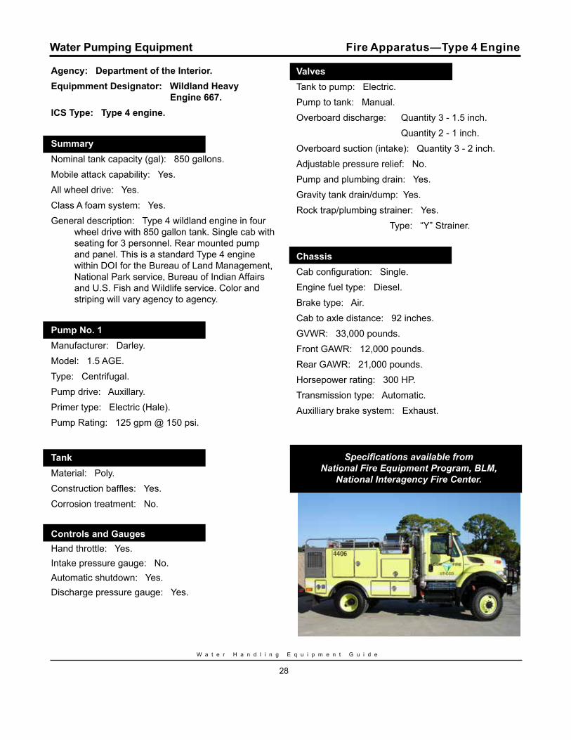
Agency: Department of the Interior. Equipmment Designator: Wildland Heavy Engine 667.ICS Type: Type 4 engine.
Summary.Nominal tank capacity (gal): 850 gallons.Mobile attack capability: Yes.All wheel drive: Yes.Class A foam system: Yes.General description: Type 4 wildland engine in four
wheel drive with 850 gallon tank. Single cab with seating for 3 personnel. Rear mounted pump and panel. This is a standard Type 4 engine within DOI for the Bureau of Land Management, National Park service, Bureau of Indian Affairs and U.S. Fish and Wildlife service. Color and striping will vary agency to agency.
Pump No. 1.Manufacturer: Darley. Model: 1.5 AGE.Type: Centrifugal.Pump drive: Auxillary.Primer type: Electric (Hale).Pump Rating: 125 gpm @ 150 psi.
Tank.Material: Poly.Construction baffles: Yes.Corrosion treatment: No.
Controls and Gauges.Hand throttle: Yes.Intake pressure gauge: No.Automatic shutdown: Yes.Discharge pressure gauge: Yes.
Fire Apparatus—Type 4 Engine
Valves.Tank to pump: Electric.Pump to tank: Manual.Overboard discharge: Quantity 3 - 1.5 inch. Quantity 2 - 1 inch.Overboard suction (intake): Quantity 3 - 2 inch.Adjustable pressure relief: No.Pump and plumbing drain: Yes.Gravity tank drain/dump: Yes.Rock trap/plumbing strainer: Yes. Type: “Y” Strainer.
Chassis.Cab configuration: Single.Engine fuel type: Diesel.Brake type: Air.Cab to axle distance: 92 inches.GVWR: 33,000 pounds.Front GAWR: 12,000 pounds.Rear GAWR: 21,000 pounds.Horsepower rating: 300 HP.Transmission type: Automatic.Auxilliary brake system: Exhaust.
Specifications available from National Fire Equipment Program, BLM,
National Interagency Fire Center.
S i x t h E d i t i o n
29
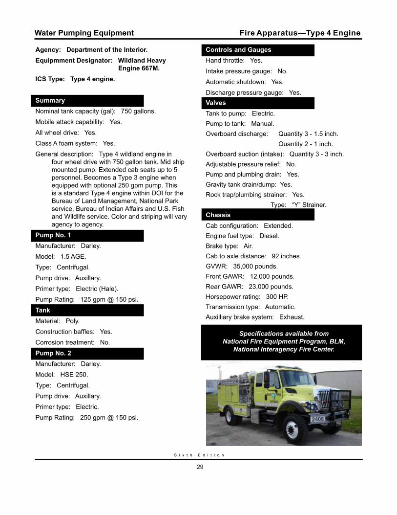
Agency: Department of the Interior. Equipmment Designator: Wildland Heavy Engine 667M.ICS Type: Type 4 engine.
Summary.Nominal tank capacity (gal): 750 gallons.Mobile attack capability: Yes.All wheel drive: Yes.Class A foam system: Yes.General description: Type 4 wildland engine in
four wheel drive with 750 gallon tank. Mid ship mounted pump. Extended cab seats up to 5 personnel. Becomes a Type 3 engine when equipped with optional 250 gpm pump. This is a standard Type 4 engine within DOI for the Bureau of Land Management, National Park service, Bureau of Indian Affairs and U.S. Fish and Wildlife service. Color and striping will vary agency to agency.
Pump No. 1.Manufacturer: Darley. Model: 1.5 AGE.Type: Centrifugal.Pump drive: Auxillary.Primer type: Electric (Hale).Pump Rating: 125 gpm @ 150 psi. Tank.Material: Poly.Construction baffles: Yes.Corrosion treatment: No.Pump No. 2.Manufacturer: Darley. Model: HSE 250.Type: Centrifugal.Pump drive: Auxillary.Primer type: Electric.Pump Rating: 250 gpm @ 150 psi.
Controls and Gauges.Hand throttle: Yes.Intake pressure gauge: No.Automatic shutdown: Yes.Discharge pressure gauge: Yes.ValvesValves. Tank to pump: Electric.Pump to tank: Manual.Overboard discharge: Quantity 3 - 1.5 inch. Quantity 2 - 1 inch.Overboard suction (intake): Quantity 3 - 3 inch.Adjustable pressure relief: No.Pump and plumbing drain: Yes.Gravity tank drain/dump: Yes.Rock trap/plumbing strainer: Yes. Type: “Y” Strainer.Chassis.Cab configuration: Extended.Engine fuel type: Diesel.Brake type: Air.Cab to axle distance: 92 inches.GVWR: 35,000 pounds.Front GAWR: 12,000 pounds.Rear GAWR: 23,000 pounds.Horsepower rating: 300 HP.Transmission type: Automatic.Auxilliary brake system: Exhaust.
Specifications available from National Fire Equipment Program, BLM,
National Interagency Fire Center.
Water Pumping Equipment Fire Apparatus—Type 4 Engine
W a t e r H a n d l i n g E q u i p m e n t G u i d e
30
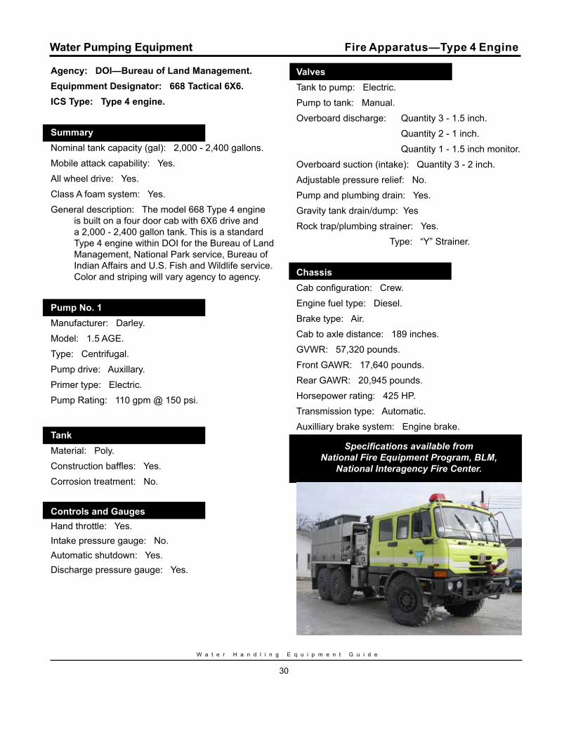
Agency: DOI—Bureau of Land Management. Equipmment Designator: 668 Tactical 6X6.ICS Type: Type 4 engine.
Summary.Nominal tank capacity (gal): 2,000 - 2,400 gallons.Mobile attack capability: Yes.All wheel drive: Yes.Class A foam system: Yes.General description: The model 668 Type 4 engine
is built on a four door cab with 6X6 drive and a 2,000 - 2,400 gallon tank. This is a standard Type 4 engine within DOI for the Bureau of Land Management, National Park service, Bureau of Indian Affairs and U.S. Fish and Wildlife service. Color and striping will vary agency to agency.
Pump No. 1.Manufacturer: Darley. Model: 1.5 AGE.Type: Centrifugal.Pump drive: Auxillary.Primer type: Electric.Pump Rating: 110 gpm @ 150 psi.
Tank.Material: Poly.Construction baffles: Yes.Corrosion treatment: No.
Controls and Gauges.Hand throttle: Yes.Intake pressure gauge: No.Automatic shutdown: Yes.Discharge pressure gauge: Yes.
Valves.Tank to pump: Electric.Pump to tank: Manual.Overboard discharge: Quantity 3 - 1.5 inch. Quantity 2 - 1 inch. Quantity 1 - 1.5 inch monitor.Overboard suction (intake): Quantity 3 - 2 inch.Adjustable pressure relief: No.Pump and plumbing drain: Yes.Gravity tank drain/dump: YesRock trap/plumbing strainer: Yes. Type: “Y” Strainer.
Chassis.Cab configuration: Crew.Engine fuel type: Diesel.Brake type: Air.Cab to axle distance: 189 inches.GVWR: 57,320 pounds.Front GAWR: 17,640 pounds.Rear GAWR: 20,945 pounds.Horsepower rating: 425 HP.Transmission type: Automatic.Auxilliary brake system: Engine brake.
Specifications available from National Fire Equipment Program, BLM,
National Interagency Fire Center.
Water Pumping Equipment Fire Apparatus—Type 4 Engine
S i x t h E d i t i o n
31
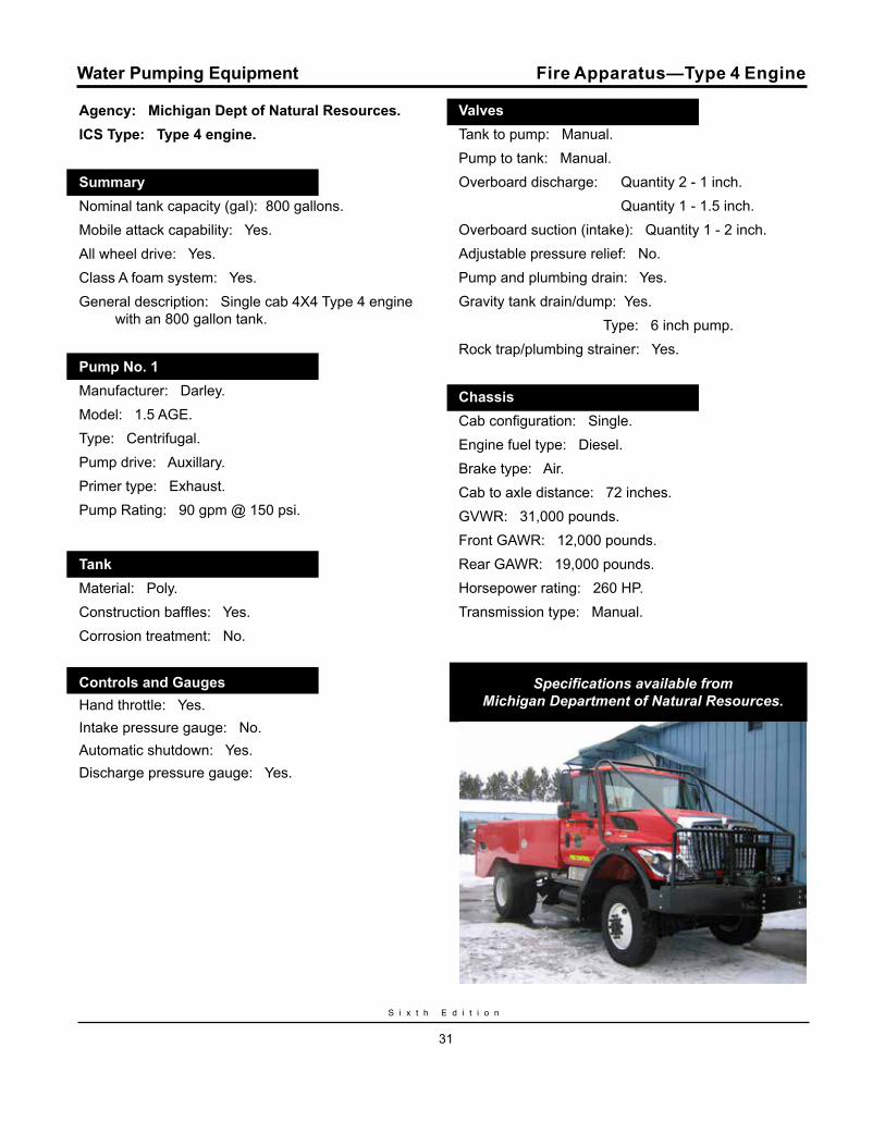
Agency: Michigan Dept of Natural Resources.ICS Type: Type 4 engine.
Summary.Nominal tank capacity (gal): 800 gallons.Mobile attack capability: Yes.All wheel drive: Yes.Class A foam system: Yes.General description: Single cab 4X4 Type 4 engine
with an 800 gallon tank.
Pump No. 1.Manufacturer: Darley. Model: 1.5 AGE.Type: Centrifugal.Pump drive: Auxillary.Primer type: Exhaust.Pump Rating: 90 gpm @ 150 psi.
Tank.Material: Poly.Construction baffles: Yes.Corrosion treatment: No.
Controls and Gauges.Hand throttle: Yes.Intake pressure gauge: No.Automatic shutdown: Yes.Discharge pressure gauge: Yes.
Valves.Tank to pump: Manual.Pump to tank: Manual.Overboard discharge: Quantity 2 - 1 inch. Quantity 1 - 1.5 inch.Overboard suction (intake): Quantity 1 - 2 inch.Adjustable pressure relief: No.Pump and plumbing drain: Yes.Gravity tank drain/dump: Yes. Type: 6 inch pump.Rock trap/plumbing strainer: Yes.
Chassis.Cab configuration: Single.Engine fuel type: Diesel.Brake type: Air.Cab to axle distance: 72 inches.GVWR: 31,000 pounds.Front GAWR: 12,000 pounds.Rear GAWR: 19,000 pounds.Horsepower rating: 260 HP.Transmission type: Manual.
Specifications available from Michigan Department of Natural Resources.
Water Pumping Equipment Fire Apparatus—Type 4 Engine
W a t e r H a n d l i n g E q u i p m e n t G u i d e
32
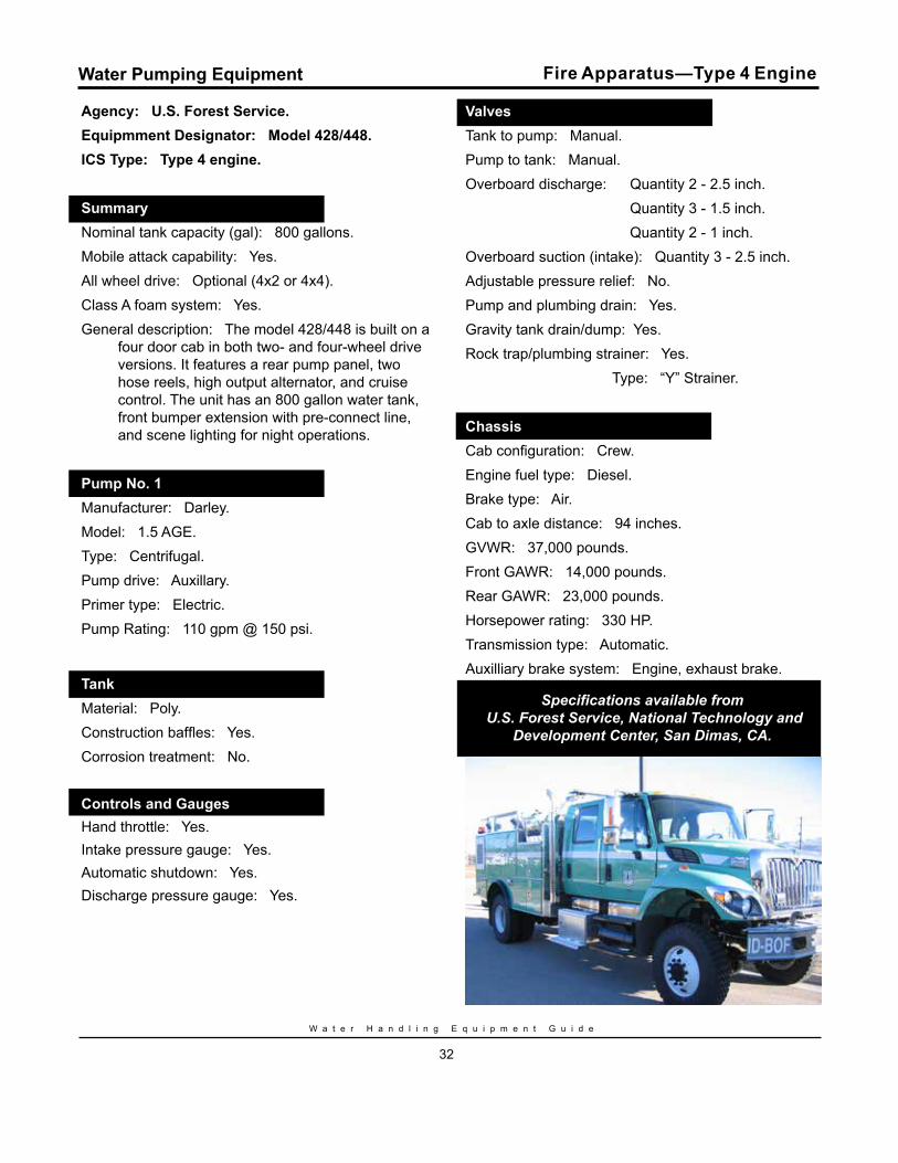
Agency: U.S. Forest Service.Equipmment Designator: Model 428/448.ICS Type: Type 4 engine.
Summary.Nominal tank capacity (gal): 800 gallons.Mobile attack capability: Yes.All wheel drive: Optional (4x2 or 4x4).Class A foam system: Yes.General description: The model 428/448 is built on a
four door cab in both two- and four-wheel drive versions. It features a rear pump panel, two hose reels, high output alternator, and cruise control. The unit has an 800 gallon water tank, front bumper extension with pre-connect line, and scene lighting for night operations.
Pump No. 1.Manufacturer: Darley. Model: 1.5 AGE.Type: Centrifugal.Pump drive: Auxillary.Primer type: Electric.Pump Rating: 110 gpm @ 150 psi.
Tank.Material: Poly.Construction baffles: Yes.Corrosion treatment: No.
Controls and Gauges.Hand throttle: Yes.Intake pressure gauge: Yes.Automatic shutdown: Yes.Discharge pressure gauge: Yes.
Valves.Tank to pump: Manual.Pump to tank: Manual.Overboard discharge: Quantity 2 - 2.5 inch. Quantity 3 - 1.5 inch. Quantity 2 - 1 inch.Overboard suction (intake): Quantity 3 - 2.5 inch.Adjustable pressure relief: No.Pump and plumbing drain: Yes.Gravity tank drain/dump: Yes.Rock trap/plumbing strainer: Yes. Type: “Y” Strainer.
Chassis.Cab configuration: Crew.Engine fuel type: Diesel.Brake type: Air.Cab to axle distance: 94 inches.GVWR: 37,000 pounds.Front GAWR: 14,000 pounds.Rear GAWR: 23,000 pounds.Horsepower rating: 330 HP.Transmission type: Automatic.Auxilliary brake system: Engine, exhaust brake.
Specifications available from U.S. Forest Service, National Technology and
Development Center, San Dimas, CA.
Water Pumping Equipment Fire Apparatus—Type 4 Engine
S i x t h E d i t i o n
33
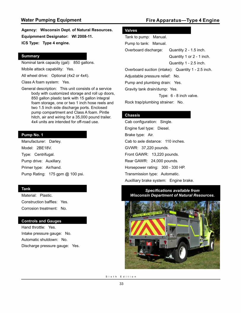
Agency: Wisconsin Dept. of Natural Resources.Equipmment Designator: WI 2008-11.ICS Type: Type 4 engine.
Summary.Nominal tank capacity (gal): 850 gallons.Mobile attack capability: Yes.All wheel drive: Optional (4x2 or 4x4).Class A foam system: Yes.General description: This unit consists of a service
body with customized storage and roll up doors, 850 gallon plastic tank with 15 gallon integral foam storage, one or two 1 inch hose reels and two 1.5 inch side discharge ports. Enclosed pump compartment and Class A foam. Pintle hitch, air and wiring for a 35,000 pound trailer. 4x4 units are intended for off-road use.
Pump No. 1.Manufacturer: Darley. Model: 2BE18V.Type: Centrifugal.Pump drive: Auxillary.Primer type: Air/hand.Pump Rating: 175 gpm @ 100 psi.
Tank.Material: Plastic.Construction baffles: Yes.Corrosion treatment: No.
Controls and Gauges.Hand throttle: Yes.Intake pressure gauge: No.Automatic shutdown: No.Discharge pressure gauge: Yes.
Valves.Tank to pump: Manual.Pump to tank: Manual.Overboard discharge: Quantity 2 - 1.5 inch. Quantity 1 or 2 - 1 inch. Quantity 1 - 2.5 inch.Overboard suction (intake): Quantity 1 - 2.5 inch.Adjustable pressure relief: No.Pump and plumbing drain: Yes.Gravity tank drain/dump: Yes. Type: 6 - 8 inch valve.Rock trap/plumbing strainer: No.
Chassis.Cab configuration: Single.Engine fuel type: Diesel.Brake type: Air.Cab to axle distance: 110 inches.GVWR: 37,220 pounds.Front GAWR: 13,220 pounds.Rear GAWR: 24,000 pounds.Horsepower rating: 300 - 330 HP.Transmission type: Automatic.Auxilliary brake system: Engine brake.
Specifications available from Wisconsin Department of Natural Resources.
Water Pumping Equipment Fire Apparatus—Type 4 Engine
W a t e r H a n d l i n g E q u i p m e n t G u i d e
34
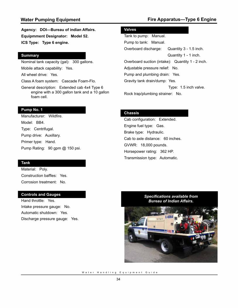
Agency: DOI—Bureau of indian Affairs. Equipmment Designator: Model 52.ICS Type: Type 6 engine.
Summary.Nominal tank capacity (gal): 300 gallons.Mobile attack capability: Yes.All wheel drive: Yes.Class A foam system: Cascade Foam-Flo.General description: Extended cab 4x4 Type 6
engine with a 300 gallon tank and a 10 gallon foam cell.
Pump No. 1.Manufacturer: Wildfire. Model: BB4.Type: Centrifugal.Pump drive: Auxillary.Primer type: Hand.Pump Rating: 90 gpm @ 150 psi.
Tank.Material: Poly.Construction baffles: Yes.Corrosion treatment: No.
Controls and Gauges.Hand throttle: Yes.Intake pressure gauge: No.Automatic shutdown: Yes.Discharge pressure gauge: Yes.
Valves.Tank to pump: Manual.Pump to tank: Manual.Overboard discharge: Quantity 3 - 1.5 inch. Quantity 1 - 1 inch.Overboard suction (intake): Quantity 1 - 2 inch.Adjustable pressure relief: No.Pump and plumbing drain: Yes.Gravity tank drain/dump: Yes. Type: 1.5 inch valve.Rock trap/plumbing strainer: No.
Chassis.Cab configuration: Extended.Engine fuel type: Gas.Brake type: Hydraulic.Cab to axle distance: 60 inches.GVWR: 18,000 pounds.Horsepower rating: 362 HP.Transmission type: Automatic.
Specifications available from Bureau of Indian Affairs.
Water Pumping Equipment Fire Apparatus—Type 6 Engine
S i x t h E d i t i o n
35
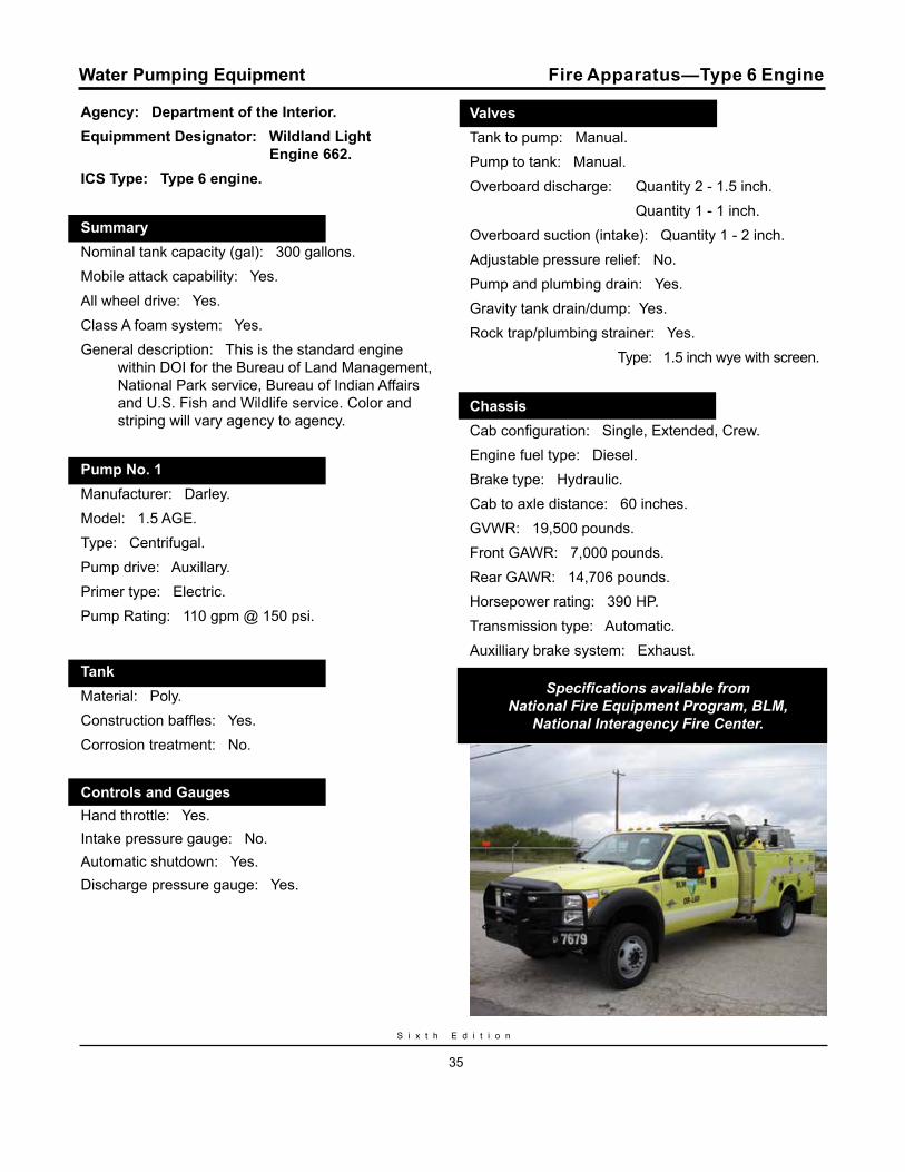
Agency: Department of the Interior.Equipmment Designator: Wildland Light Engine 662.ICS Type: Type 6 engine.
Summary.Nominal tank capacity (gal): 300 gallons.Mobile attack capability: Yes.All wheel drive: Yes.Class A foam system: Yes.General description: This is the standard engine
within DOI for the Bureau of Land Management, National Park service, Bureau of Indian Affairs and U.S. Fish and Wildlife service. Color and striping will vary agency to agency.
Pump No. 1.Manufacturer: Darley. Model: 1.5 AGE.Type: Centrifugal.Pump drive: Auxillary.Primer type: Electric.Pump Rating: 110 gpm @ 150 psi.
Tank.Material: Poly.Construction baffles: Yes.Corrosion treatment: No.
Controls and Gauges.Hand throttle: Yes.Intake pressure gauge: No.Automatic shutdown: Yes.Discharge pressure gauge: Yes.
Valves.Tank to pump: Manual.Pump to tank: Manual.Overboard discharge: Quantity 2 - 1.5 inch. Quantity 1 - 1 inch.Overboard suction (intake): Quantity 1 - 2 inch.Adjustable pressure relief: No.Pump and plumbing drain: Yes.Gravity tank drain/dump: Yes.Rock trap/plumbing strainer: Yes. Type: 1.5 inch wye with screen.
Chassis.Cab configuration: Single, Extended, Crew.Engine fuel type: Diesel.Brake type: Hydraulic.Cab to axle distance: 60 inches.GVWR: 19,500 pounds.Front GAWR: 7,000 pounds.Rear GAWR: 14,706 pounds.Horsepower rating: 390 HP.Transmission type: Automatic.Auxilliary brake system: Exhaust.
Specifications available from National Fire Equipment Program, BLM,
National Interagency Fire Center.
Water Pumping Equipment Fire Apparatus—Type 6 Engine
W a t e r H a n d l i n g E q u i p m e n t G u i d e
36
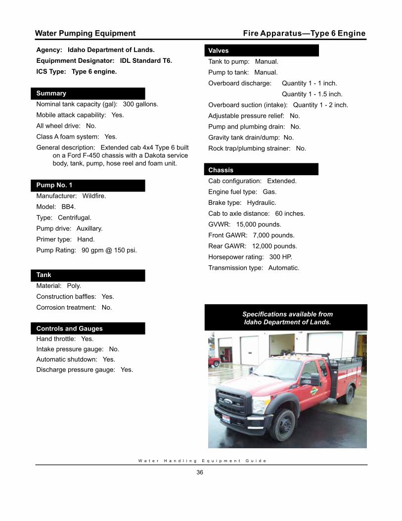
Agency: Idaho Department of Lands.Equipmment Designator: IDL Standard T6.ICS Type: Type 6 engine.
Summary.Nominal tank capacity (gal): 300 gallons.Mobile attack capability: Yes.All wheel drive: No.Class A foam system: Yes.General description: Extended cab 4x4 Type 6 built
on a Ford F-450 chassis with a Dakota service body, tank, pump, hose reel and foam unit.
Pump No. 1.Manufacturer: Wildfire. Model: BB4.Type: Centrifugal.Pump drive: Auxillary.Primer type: Hand.Pump Rating: 90 gpm @ 150 psi.
Tank.Material: Poly.Construction baffles: Yes.Corrosion treatment: No.
Controls and Gauges.Hand throttle: Yes.Intake pressure gauge: No.Automatic shutdown: Yes.Discharge pressure gauge: Yes.
Valves.Tank to pump: Manual.Pump to tank: Manual.Overboard discharge: Quantity 1 - 1 inch. Quantity 1 - 1.5 inch.Overboard suction (intake): Quantity 1 - 2 inch.Adjustable pressure relief: No.Pump and plumbing drain: No.Gravity tank drain/dump: No.Rock trap/plumbing strainer: No.
Chassis.Cab configuration: Extended.Engine fuel type: Gas.Brake type: Hydraulic.Cab to axle distance: 60 inches.GVWR: 15,000 pounds.Front GAWR: 7,000 pounds.Rear GAWR: 12,000 pounds.Horsepower rating: 300 HP.Transmission type: Automatic.
Specifications available from Idaho Department of Lands.
Water Pumping Equipment Fire Apparatus—Type 6 Engine
S i x t h E d i t i o n
37
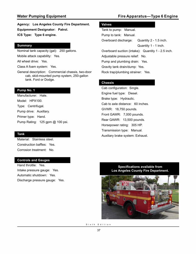
Agency: Los Angeles County Fire Department.Equipmment Designator: Patrol.ICS Type: Type 6 engine.
Summary.Nominal tank capacity (gal): 250 gallons.Mobile attack capability: Yes.All wheel drive: Yes.Class A foam system: Yes.General description: Commercial chassis, two-door
cab, skid-mounted pump system, 250-gallon tank. Ford or Dodge.
Pump No. 1.Manufacturer: Hale. Model: HPX100.Type: Centrifugal.Pump drive: Auxillary.Primer type: Hand.Pump Rating: 125 gpm @ 100 psi.
Tank.Material: Stainless steel.Construction baffles: Yes.Corrosion treatment: No.
Controls and Gauges.Hand throttle: Yes.Intake pressure gauge: Yes.Automatic shutdown: Yes.Discharge pressure gauge: Yes.
Fire Apparatus—Type 6 Engine
Valves.Tank to pump: Manual.Pump to tank: Manual.Overboard discharge: Quantity 2 - 1.5 inch. Quantity 1 - 1 inch.Overboard suction (intake): Quantity 1 - 2.5 inch.Adjustable pressure relief: No.Pump and plumbing drain: Yes.Gravity tank drain/dump: Yes.Rock trap/plumbing strainer: Yes.
Chassis.Cab configuration: Single.Engine fuel type: Diesel.Brake type: Hydraulic.Cab to axle distance: 60 inches.GVWR: 18,750 pounds.Front GAWR: 7,000 pounds.Rear GAWR: 13,500 pounds.Horsepower rating: 305 HP.Transmission type: Manual.Auxiliary brake system: Exhaust.
Specifications available from Los Angeles County Fire Department.
Water Pumping Equipment
W a t e r H a n d l i n g E q u i p m e n t G u i d e
38
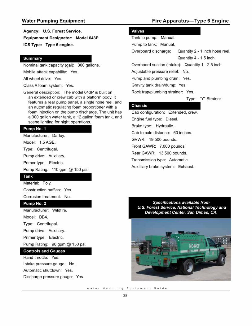
Agency: U.S. Forest Service.Equipmment Designator: Model 643P.ICS Type: Type 6 engine.
Summary.Nominal tank capacity (gal): 300 gallons.Mobile attack capability: Yes.All wheel drive: Yes.Class A foam system: Yes.General description: The model 643P is built on
an extended or crew cab with a platform body. It features a rear pump panel, a single hose reel, and an automatic regulating foam proportioner with a foam injection on the pump discharge. The unit has a 300 gallon water tank, a 12 gallon foam tank, and scene lighting for night operations.
Pump No. 1.Manufacturer: Darley. Model: 1.5 AGE.Type: Centrifugal.Pump drive: Auxillary.Primer type: Electric.Pump Rating: 110 gpm @ 150 psi. Tank.Material: Poly.Construction baffles: Yes.Corrosion treatment: No.Pump No. 2.Manufacturer: Wildfire. Model: BB4.Type: Centrifugal.Pump drive: Auxillary.Primer type: Electric.Pump Rating: 90 gpm @ 150 psi. Controls and Gauges.Hand throttle: Yes.Intake pressure gauge: No.Automatic shutdown: Yes.Discharge pressure gauge: Yes.Valves
Valves.Tank to pump: Manual.Pump to tank: Manual.Overboard discharge: Quantity 2 - 1 inch hose reel. Quantity 4 - 1.5 inch.Overboard suction (intake): Quantity 1 - 2.5 inch.Adjustable pressure relief: No.Pump and plumbing drain: Yes.Gravity tank drain/dump: Yes.Rock trap/plumbing strainer: Yes. Type: “Y” Strainer.Chassis.Cab configuration: Extended, crew.Engine fuel type: Diesel.Brake type: Hydraulic.Cab to axle distance: 60 inches.GVWR: 19,500 pounds.Front GAWR: 7,000 pounds.Rear GAWR: 13,500 pounds.Transmission type: Automatic.Auxilliary brake system: Exhaust.
Specifications available from U.S. Forest Service, National Technology and
Development Center, San Dimas, CA.
Water Pumping Equipment Fire Apparatus—Type 6 Engine
S i x t h E d i t i o n
39
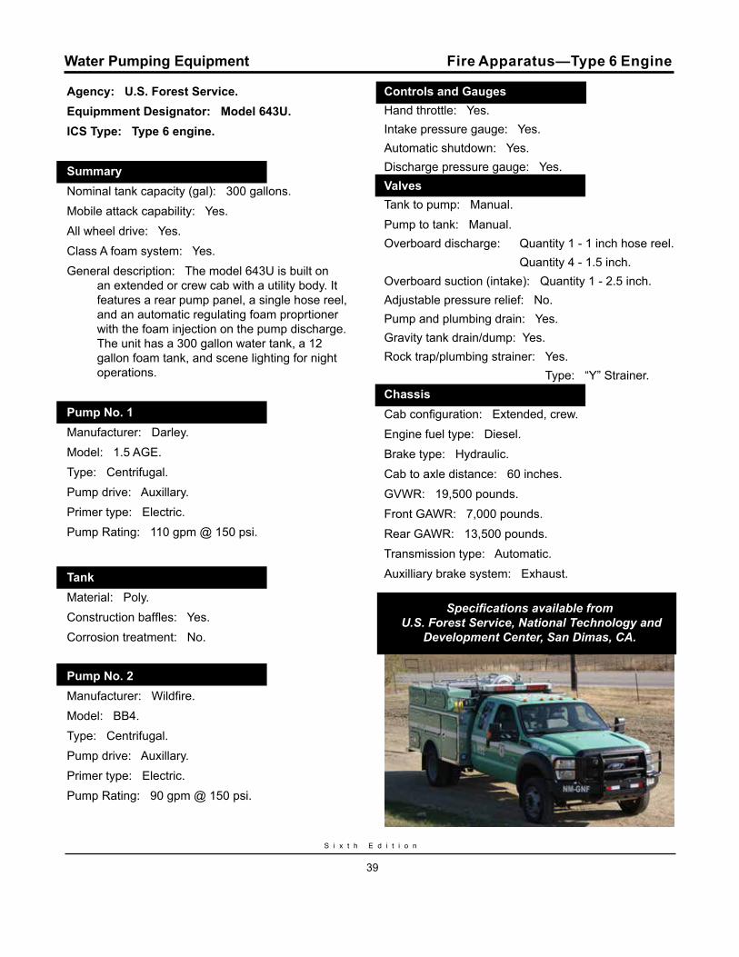
Agency: U.S. Forest Service.Equipmment Designator: Model 643U.ICS Type: Type 6 engine.
Summary.Nominal tank capacity (gal): 300 gallons.Mobile attack capability: Yes.All wheel drive: Yes.Class A foam system: Yes.General description: The model 643U is built on
an extended or crew cab with a utility body. It features a rear pump panel, a single hose reel, and an automatic regulating foam proprtioner with the foam injection on the pump discharge. The unit has a 300 gallon water tank, a 12 gallon foam tank, and scene lighting for night operations.
Pump No. 1.Manufacturer: Darley. Model: 1.5 AGE.Type: Centrifugal.Pump drive: Auxillary.Primer type: Electric.Pump Rating: 110 gpm @ 150 psi.
Tank.Material: Poly.Construction baffles: Yes.Corrosion treatment: No.
Pump No. 2.Manufacturer: Wildfire. Model: BB4.Type: Centrifugal.Pump drive: Auxillary.Primer type: Electric.Pump Rating: 90 gpm @ 150 psi.
Controls and Gauges.Hand throttle: Yes.Intake pressure gauge: Yes.Automatic shutdown: Yes.Discharge pressure gauge: Yes.ValveValves.Tank to pump: Manual.Pump to tank: Manual.Overboard discharge: Quantity 1 - 1 inch hose reel. Quantity 4 - 1.5 inch.Overboard suction (intake): Quantity 1 - 2.5 inch.Adjustable pressure relief: No.Pump and plumbing drain: Yes.Gravity tank drain/dump: Yes.Rock trap/plumbing strainer: Yes. Type: “Y” Strainer.Chassis.Cab configuration: Extended, crew.Engine fuel type: Diesel.Brake type: Hydraulic.Cab to axle distance: 60 inches.GVWR: 19,500 pounds.Front GAWR: 7,000 pounds.Rear GAWR: 13,500 pounds.Transmission type: Automatic.Auxilliary brake system: Exhaust.
Specifications available from U.S. Forest Service, National Technology and
Development Center, San Dimas, CA.
Water Pumping Equipment Fire Apparatus—Type 6 Engine
W a t e r H a n d l i n g E q u i p m e n t G u i d e
40
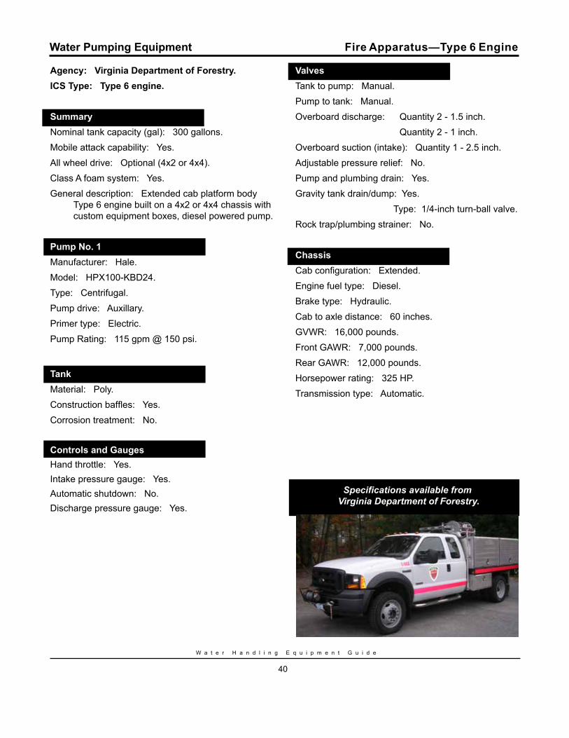
Agency: Virginia Department of Forestry.ICS Type: Type 6 engine.
Summary.Nominal tank capacity (gal): 300 gallons.Mobile attack capability: Yes.All wheel drive: Optional (4x2 or 4x4).Class A foam system: Yes.General description: Extended cab platform body
Type 6 engine built on a 4x2 or 4x4 chassis with custom equipment boxes, diesel powered pump.
Pump No. 1.Manufacturer: Hale. Model: HPX100-KBD24.Type: Centrifugal.Pump drive: Auxillary.Primer type: Electric.Pump Rating: 115 gpm @ 150 psi.
Tank.Material: Poly.Construction baffles: Yes.Corrosion treatment: No.
Controls and Gauges.Hand throttle: Yes.Intake pressure gauge: Yes.Automatic shutdown: No.Discharge pressure gauge: Yes.
Valves.Tank to pump: Manual.Pump to tank: Manual.Overboard discharge: Quantity 2 - 1.5 inch. Quantity 2 - 1 inch.Overboard suction (intake): Quantity 1 - 2.5 inch.Adjustable pressure relief: No.Pump and plumbing drain: Yes.Gravity tank drain/dump: Yes. Type: 1/4-inch turn-ball valve.Rock trap/plumbing strainer: No.
Chassis.Cab configuration: Extended.Engine fuel type: Diesel.Brake type: Hydraulic.Cab to axle distance: 60 inches.GVWR: 16,000 pounds.Front GAWR: 7,000 pounds.Rear GAWR: 12,000 pounds.Horsepower rating: 325 HP.Transmission type: Automatic.
Specifications available from Virginia Department of Forestry.
Water Pumping Equipment Fire Apparatus—Type 6 Engine
S i x t h E d i t i o n
41
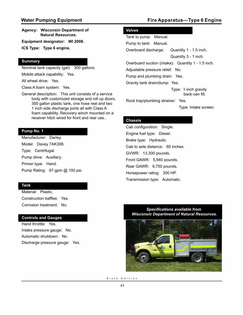
Agency: Wisconsin Department of Natural Resources.Equipment designator: WI 2008.ICS Type: Type 6 engine.
Summary.Nominal tank capacity (gal): 300 gallons.Mobile attack capability: Yes.All wheel drive: Yes.Class A foam system: Yes.General description: This unit consists of a service
body with customized storage and roll up doors, 300 gallon plastic tank, one hose reel and two 1 inch side discharge ports all with Class A foam capability. Recovery winch mounted on a receiver hitch wired for front and rear use..
Pump No. 1.Manufacturer: Darley. Model: Davey 7AK308.Type: Centrifugal.Pump drive: Auxillary.Primer type: Hand.Pump Rating: 67 gpm @ 100 psi.
Tank.Material: Plastic.Construction baffles: Yes.Corrosion treatment: No.
Controls and Gauges.Hand throttle: Yes.Intake pressure gauge: No.Automatic shutdown: No.Discharge pressure gauge: Yes.
Fire Apparatus—Type 6 Engine
Valves.Tank to pump: Manual.Pump to tank: Manual.Overboard discharge: Quantity 1 - 1.5 inch. Quantity 3 - 1 inch.Overboard suction (intake): Quantity 1 - 1.5 inch.Adjustable pressure relief: No.Pump and plumbing drain: Yes.Gravity tank drain/dump: Yes. Type: 1-inch gravity back-can fill.Rock trap/plumbing strainer: Yes. Type: Intake screen.
Chassis.Cab configuration: Single.Engine fuel type: Diesel.Brake type: Hydraulic.Cab to axle distance: 60 inches.GVWR: 13,300 pounds.Front GAWR: 5,940 pounds.Rear GAWR: 9,750 pounds.Horsepower rating: 300 HP.Transmission type: Automatic.
Specifications available from Wisconsin Department of Natural Resources.
Water Pumping Equipment
W a t e r H a n d l i n g E q u i p m e n t G u i d e
42
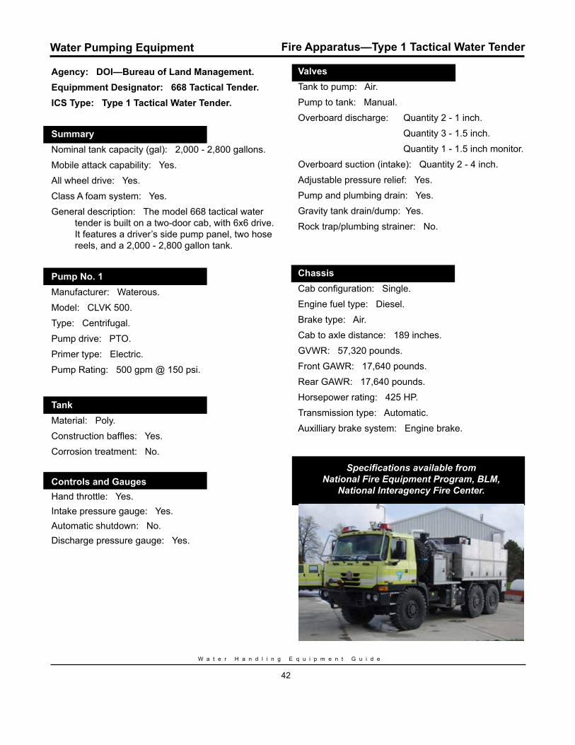
Agency: DOI—Bureau of Land Management. Equipmment Designator: 668 Tactical Tender.ICS Type: Type 1 Tactical Water Tender.
Summary.Nominal tank capacity (gal): 2,000 - 2,800 gallons.Mobile attack capability: Yes.All wheel drive: Yes.Class A foam system: Yes.General description: The model 668 tactical water
tender is built on a two-door cab, with 6x6 drive. It features a driver’s side pump panel, two hose reels, and a 2,000 - 2,800 gallon tank.
Pump No. 1.Manufacturer: Waterous. Model: CLVK 500.Type: Centrifugal.Pump drive: PTO.Primer type: Electric.Pump Rating: 500 gpm @ 150 psi.
Tank.Material: Poly.Construction baffles: Yes.Corrosion treatment: No.
Controls and Gauges.Hand throttle: Yes.Intake pressure gauge: Yes.Automatic shutdown: No.Discharge pressure gauge: Yes.
Valves.Tank to pump: Air.Pump to tank: Manual.Overboard discharge: Quantity 2 - 1 inch. Quantity 3 - 1.5 inch. Quantity 1 - 1.5 inch monitor.Overboard suction (intake): Quantity 2 - 4 inch.Adjustable pressure relief: Yes.Pump and plumbing drain: Yes.Gravity tank drain/dump: Yes.Rock trap/plumbing strainer: No.
Chassis.Cab configuration: Single.Engine fuel type: Diesel.Brake type: Air.Cab to axle distance: 189 inches.GVWR: 57,320 pounds.Front GAWR: 17,640 pounds.Rear GAWR: 17,640 pounds.Horsepower rating: 425 HP.Transmission type: Automatic.Auxilliary brake system: Engine brake.
Specifications available from National Fire Equipment Program, BLM,
National Interagency Fire Center.
Water Pumping Equipment Fire Apparatus—Type 1 Tactical Water Tender
S i x t h E d i t i o n
43
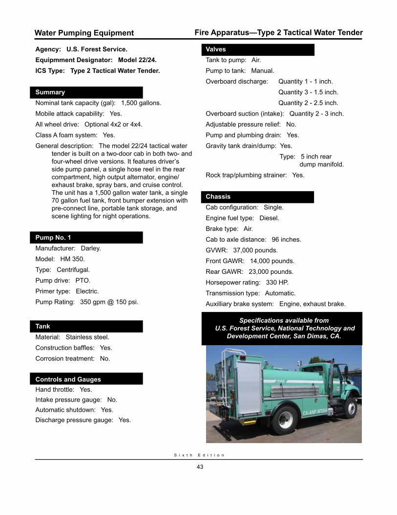
Agency: U.S. Forest Service. Equipmment Designator: Model 22/24.ICS Type: Type 2 Tactical Water Tender.
Summary.Nominal tank capacity (gal): 1,500 gallons.Mobile attack capability: Yes.All wheel drive: Optional 4x2 or 4x4.Class A foam system: Yes.General description: The model 22/24 tactical water
tender is built on a two-door cab in both two- and four-wheel drive versions. It features driver’s side pump panel, a single hose reel in the rear compartment, high output alternator, engine/exhaust brake, spray bars, and cruise control. The unit has a 1,500 gallon water tank, a single 70 gallon fuel tank, front bumper extension with pre-connect line, portable tank storage, and scene lighting for night operations.
Pump No. 1.Manufacturer: Darley. Model: HM 350.Type: Centrifugal.Pump drive: PTO.Primer type: Electric.Pump Rating: 350 gpm @ 150 psi.
Tank.Material: Stainless steel.Construction baffles: Yes.Corrosion treatment: No.
Controls and Gauges.Hand throttle: Yes.Intake pressure gauge: No.Automatic shutdown: Yes.Discharge pressure gauge: Yes.
Valves.Tank to pump: Air. Pump to tank: Manual.Overboard discharge: Quantity 1 - 1 inch. Quantity 3 - 1.5 inch. Quantity 2 - 2.5 inch.Overboard suction (intake): Quantity 2 - 3 inch.Adjustable pressure relief: No.Pump and plumbing drain: Yes.Gravity tank drain/dump: Yes. Type: 5 inch rear dump manifold.Rock trap/plumbing strainer: Yes.
Chassis.Cab configuration: Single.Engine fuel type: Diesel.Brake type: Air.Cab to axle distance: 96 inches.GVWR: 37,000 pounds.Front GAWR: 14,000 pounds.Rear GAWR: 23,000 pounds.Horsepower rating: 330 HP.Transmission type: Automatic.Auxilliary brake system: Engine, exhaust brake.
Specifications available from U.S. Forest Service, National Technology and
Development Center, San Dimas, CA.
Water Pumping Equipment Fire Apparatus—Type 2 Tactical Water Tender

W a t e r H a n d l i n g E q u i p m e n t G u i d e
44
Water Pumping Equipment
Agency: Los Angeles County Fire Department. ICS Type: Type 1 Tactical Water Tender.
Summary.Nominal tank capacity (gal): 2,500 gallons.Mobile attack capability: Yes.All wheel drive: Yes.Class A foam system: No.General description: Commercial chassis, two-door
cab, 500 gallons per minute PTO pump, 2,500 gallon tank. Intenational, Freightliner or Peterbilt.
Pump No. 1.Manufacturer: Hale. Model: AP 500.Type: Centrifugal.Pump drive: PTO.Primer type: Electric.Pump Rating: 500 gpm @ 150 psi.
Tank.Material: Stainless steel.Construction baffles: Yes.Corrosion treatment: No.
Controls and Gauges.Hand throttle: Yes.Intake pressure gauge: Yes.Automatic shutdown: No.Discharge pressure gauge: Yes.
Valves.Tank to pump: Manual.Pump to tank: Manual.Overboard discharge: Quantity 4 - 2.5 inch. Quantity 2 - 1.5 inch.Overboard suction (intake): Quantity 2 - 2.5 inch.Adjustable pressure relief: No.Pump and plumbing drain: Yes.Gravity tank drain/dump: Yes.Rock trap/plumbing strainer: Yes.
Chassis.Cab configuration: Single.GVWR: 56,000 pounds.Front GAWR: 16,000 pounds.Rear GAWR: 40,000 pounds.Horsepower rating: 400 HP.Transmission type: Automatic.Auxilliary brake system: Exhaust.
Specifications available from Los Angeles County Fire Department.
Fire Apparatus—Type 2 Support Water Tender
S i x t h E d i t i o n
45
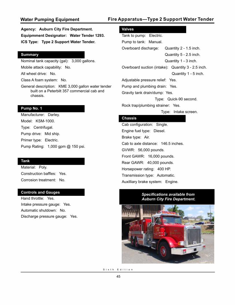
Agency: Auburn City Fire Department.Equipmment Designator: Water Tender 1293.ICS Type: Type 2 Support Water Tender.
Summary..Nominal tank capacity (gal): 3,000 gallons.Mobile attack capability: No.All wheel drive: No.Class A foam system: No.General description: KME 3,000 gallon water tender
built on a Peterbilt 357 commercial cab and chassis.
Pump No. 1..Manufacturer: Darley. Model: KSM-1000.Type: Centrifugal.Pump drive: Mid ship.Primer type: Electric.Pump Rating: 1,000 gpm @ 150 psi.
Tank..Material: Poly.Construction baffles: Yes.Corrosion treatment: No.
Controls and Gauges..Hand throttle: Yes.Intake pressure gauge: Yes.Automatic shutdown: No.Discharge pressure gauge: Yes.
Valves..Tank to pump: Electric.Pump to tank: Manual.Overboard discharge: Quantity 2 - 1.5 inch. Quantity 5 - 2.5 inch. Quantity 1 - 3 inch.Overboard suction (intake): Quantity 3 - 2.5 inch. Quantity 1 - 5 inch.Adjustable pressure relief: Yes.Pump and plumbing drain: Yes.Gravity tank drain/dump: Yes. Type: Quick-90 second.Rock trap/plumbing strainer: Yes. Type: Intake screen.Chassis..Cab configuration: Single.Engine fuel type: Diesel.Brake type: Air.Cab to axle distance: 146.5 inches.GVWR: 56,000 pounds.Front GAWR: 16,000 pounds.Rear GAWR: 40,000 pounds.Horsepower rating: 400 HP.Transmission type: Automatic.Auxilliary brake system: Engine.
Specifications available from Auburn City Fire Department.
Water Pumping Equipment Fire Apparatus—Type 2 Support Water Tender
W a t e r H a n d l i n g E q u i p m e n t G u i d e
46
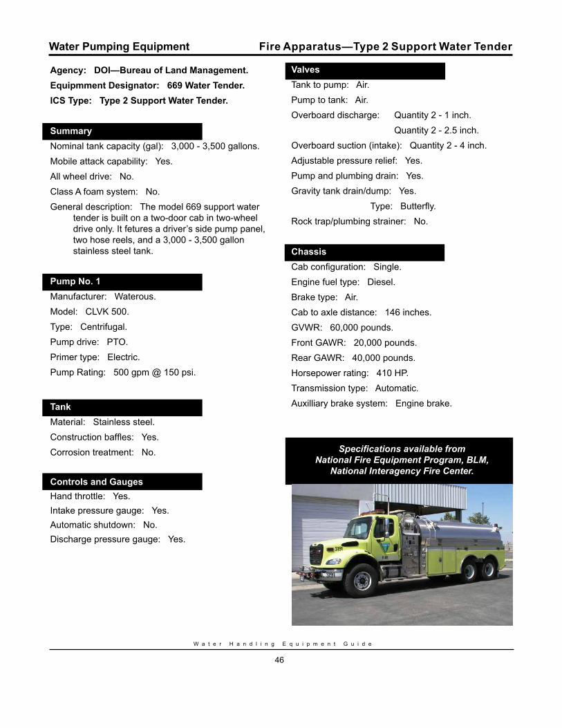
Agency: DOI—Bureau of Land Management.Equipmment Designator: 669 Water Tender.ICS Type: Type 2 Support Water Tender.
Summary..Nominal tank capacity (gal): 3,000 - 3,500 gallons.Mobile attack capability: Yes.All wheel drive: No.Class A foam system: No.General description: The model 669 support water
tender is built on a two-door cab in two-wheel drive only. It fetures a driver’s side pump panel, two hose reels, and a 3,000 - 3,500 gallon stainless steel tank.
Pump No. 1..Manufacturer: Waterous. Model: CLVK 500.Type: Centrifugal.Pump drive: PTO.Primer type: Electric.Pump Rating: 500 gpm @ 150 psi.
Tank..Material: Stainless steel.Construction baffles: Yes.Corrosion treatment: No.
Controls and Gauges..Hand throttle: Yes.Intake pressure gauge: Yes.Automatic shutdown: No.Discharge pressure gauge: Yes.
Valves..Tank to pump: Air.Pump to tank: Air.Overboard discharge: Quantity 2 - 1 inch. Quantity 2 - 2.5 inch.Overboard suction (intake): Quantity 2 - 4 inch.Adjustable pressure relief: Yes.Pump and plumbing drain: Yes.Gravity tank drain/dump: Yes. Type: Butterfly.Rock trap/plumbing strainer: No.
Chassis..Cab configuration: Single.Engine fuel type: Diesel.Brake type: Air.Cab to axle distance: 146 inches.GVWR: 60,000 pounds.Front GAWR: 20,000 pounds.Rear GAWR: 40,000 pounds.Horsepower rating: 410 HP.Transmission type: Automatic.Auxilliary brake system: Engine brake.
Specifications available from National Fire Equipment Program, BLM,
National Interagency Fire Center.
Water Pumping Equipment Fire Apparatus—Type 2 Support Water Tender
S i x t h E d i t i o n
47
Water Pumping Equipment Water Tanks
D. Water TanksWater tank design should contribute to the safety and longevity of the fire vehicle. The vehicle’s center of gravity should be as low as possible, and because a tank full of water is very heavy, the placement and size of tank is important. Low profile rectangular shaped tanks are preferred. They provide good stability on side slopes and while driving. Tanks should be placed at a position on the vehicle frame that will correctly distribute the weight of water to both front and rear axles under loaded conditions. This position is normally found on, or just in front of the rear axle. If the payload is too far forward, the result is often overloading of the front axle. If it is too far to the rear, the steering of the vehicle will be affected.
Baffles in the tank are essential to prevent rapid movement of water on slopes, cornering, and stopping. Without baffles, inertia of the water in the tank could cause vehicle rollover, contribute to tank failure, or cause braking difficulties. When installed, baffles should allow movement of water at the bottom of the tank and airflow at the top.
Tanks may be constructed of mild steel, stainless steel, fiberglass, polypropylene, aluminum, or polyurethane. Choice of material will be based on cost, ease of manufacture, tank weight, and resistance to corrosion. Steel tanks should be coated to protect from corrosion. Stainless steel may be more expensive, but the costs may be offset by factors such as warranties, longevity, ease of maintenance, and resistance to corrosion.
Fiberglass tanks are generally more costly than steel tanks, but are corrosion free.
High impact copolymer plastics (polypropylene) are the material of choice for the construction of fire engine water tanks by a large number of municipalities, States, and Federal agencies. This material is extremely strong, durable, and is ultraviolet-light stabilized to prevent deterioration from exposure to sunlight. This material has a long service life, cannot be affected by fire fighting chemicals, and can be used in potable water applications. This material can be used in the construction of tanks in almost any size or shape.
Polyurethane tanks should be avoided if at all possible. Plastics of this type are normally found in rotationally molded round tanks. These tanks tend to be brittle and subject to breakage from impact. They are normally not stabilized to resist deterioration due to sunlight (ultraviolet rays).
Due to the cleaning action of foam concentrate in solution, steel tanks in fire equipment with a foam system should be avoided if possible. Foam concentrates reduce the useful life of steel tanks several fold. Tank fabrication should be left to experienced manufacturers possessing the experience to properly design and engineer the tanks, baffles, inlets, outlets, and sumps.
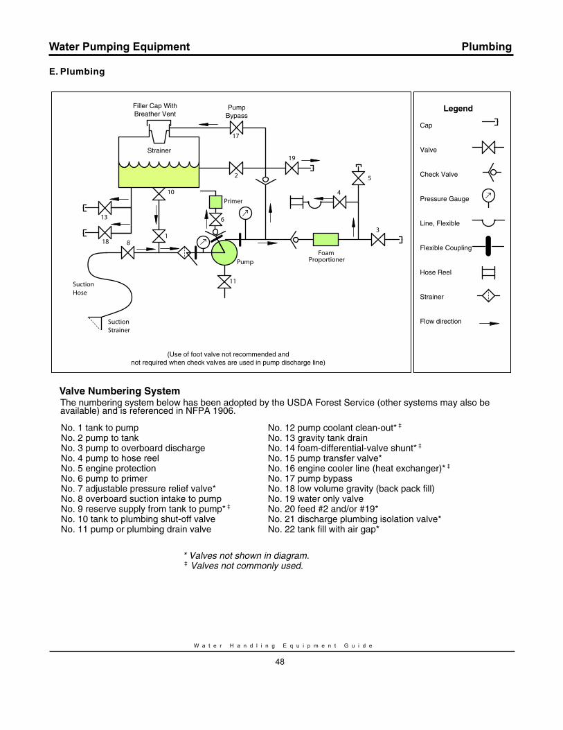
W a t e r H a n d l i n g E q u i p m e n t G u i d e
48
Water Pumping Equipment Plumbing
E. Plumbing
2
19
3
5
4
11
6
18
13
10
Primer
Pump
Strainer
FoamProportioner
SuctionStrainer
SuctionHose
Filler Cap WithBreather Vent
18
17
PumpBypass
No. 1 tank to pumpNo. 2 pump to tankNo. 3 pump to overboard dischargeNo. 4 pump to hose reelNo. 5 engine protection No. 6 pump to primerNo. 7 adjustable pressure relief valve*No. 8 overboard suction intake to pumpNo. 9 reserve supply from tank to pump* ‡ No. 10 tank to plumbing shut-off valveNo. 11 pump or plumbing drain valve
No. 12 pump coolant clean-out* ‡ No. 13 gravity tank drainNo. 14 foam-differential-valve shunt* ‡ No. 15 pump transfer valve*No. 16 engine cooler line (heat exchanger)* ‡ No. 17 pump bypassNo. 18 low volume gravity (back pack fill)No. 19 water only valveNo. 20 feed #2 and/or #19*No. 21 discharge plumbing isolation valve*No. 22 tank fill with air gap*
* Valves not shown in diagram. ‡ Valves not commonly used.
(Use of foot valve not recommended andnot required when check valves are used in pump discharge line)
Legend
Cap
Valve
Check Valve
Pressure Gauge
Line, Flexible
Flexible Coupling
Hose Reel
Strainer
Flow direction
Valve Numbering SystemThe numbering system below has been adopted by the USDA Forest Service (other systems may also be available) and is referenced in NFPA 1906.
CH
AP
TE
R I
IF
OA
M
GE
NE
RA
TI
NG
E
QU
IP
ME
NT

S i x t h E d i t i o n
51
Foam Generating Equipment
II. FOAm GENErATING EquIPmENT
A. Foam ProportionersThere are a number of systems used to proportion foam concentrate into water streams for use with standard nozzles, aspirating nozzles, or compressed air foam systems (CAFS). The two basic types of foam concentrate proportioning systems are manually regulated and automatic regulating. The system that gives the most consistent and desirable results is an automatic regulating proportioning system that injects directly into the discharge side of the water pump.
Manually regulated proportioning systems include:• Batch mixing• Suction-side proportioner• In-line eductor • Variable flow bypass eductor• Around-the-pump proportioner• Direct injection manually regulated proportioner
Automatic regulating proportioning systems include:
• Balanced pressure venturi proportioning systems —Bladder tank proportioner —Pump proportioner• Water motor meter proportioner• Direct injection automatic regulating proportioner
1. manually regulated Proportioning SystemsManual regulation systems, must be monitored and changed manually. They have less precise regulation of concentrate addition and the resulting foam quality is highly variable.
a. Batch mixingThe simplest method of making a foam solution is to manually add foam concentrate to the water supply. This method, called batch mixing, is convenient for conventional water pumping systems. A measured volume of concentrate is poured into a measured volume of water to yield a foam solution of the recommended strength. Batching is potentially wasteful
because the required volumes of both water and concentrate must be estimated, especially when refilling a partially full tank.The concentrate should be added to water, because adding water to the foam concentrate causes excessive foaming in the tank as the water is added. Mixing or recirculation of the concentrate/water mixture is required to obtain a homogeneous solution. The solution should be used as soon as possible for optimum performance. Despite a number of limitations, batch mixing is a common proportioning method for engines, portable tanks, bladders, and extinguishers, and is considered a backup method if the on-line proportioner fails to work.
b. Suction-side proportioner The suction-side proportioner uses a water pump vacuum to add foam concentrate, via an in-line tee and a regulating valve, to the water stream on the inlet side of the pump. At specific flow conditions the regulator is proportional. However, the in-line tee has no influence on vacuum, so the regulator cannot maintain a given mix ratio as waterflow changes without a manual adjustment. Because the regulator sends concentrate through the pump and the tank, when recirculating, its limitations are similar to those of batch mixing. System will not work with positive pump inlet pressure.
c. In-line eductorThe in-line eductor (or in-line proportioning system) drafts foam concentrate from a container to the pressure side of the water stream using venturi action. As pressurized water flows through the venturi, an area of negative pressure is created at the venturi throat. Atmospheric pressure forces the foam concentrate into the negative pressure area of the eductor.
Eductors work on any pump that can generate sufficient pressure and are compatible with pump capabilities. They are usually proportional at one waterflow rate. Because they are designed to operate
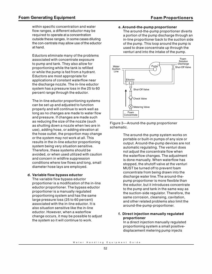
W a t e r H a n d l i n g E q u i p m e n t G u i d e
52
Foam Generating Equipment
within specific concentration and water flow ranges, a different eductor may be required to operate at a concentration outside these ranges. In some cases diluting the con-centrate may allow use of the eductor at hand.
Eductors eliminate many of the problems associated with concentrate exposure to pump and tank. They also allow for proportioning while the tank is refilled or while the pump is fed from a hydrant. Eductors are most appropriate for applications of constant waterflow near the discharge nozzle. The in-line eductor system has a pressure loss in the 25 to 60 percent range through the eductor.
The in-line eductor proportioning systems can be set up and adjusted to function properly and will continue to work well as long as no changes are made to water flow and pressure. If changes are made such as reducing the size of the nozzle (such as shutting down a nozzle when two are in use), adding hose, or adding elevation at the hose outlet, the proportion may change or the system may not work at all. This results in the in-line eductor proportioning system being very situation sensitive. Therefore, these systems should be avoided, or when used utilized with caution and concern in wildfire suppression conditions where low flows and long, small diameter hose lays are employed.
d. variable flow bypass eductorThe variable flow bypass eductor proportioner is a modification of the in-line eductor proportioner. The bypass eductor proportioner is a manually regulated proportioning system and has the same large pressure loss (25 to 60 percent) associated with the in-line eductor. It is also situation sensitive like the in-line eductor. However, when a waterflow change occurs, it may be possible to adjust the system so it will continue to work.
e. Around-the-pump proportionerThe around-the-pump proportioner diverts a portion of the pump discharge through an in-line proportioner back to the suction side of the pump. This loop around the pump is used to draw concentrate up through the venturi and into the intake of the pump.
PumpWaterSuction
Line
Eductor
Shut-Off Valve
Shut-Off Valve
Check Valve
Metering Valve
FoamConcentrate
Foam Solution
Discharge
Figure 3—Around-the-pump proportioner schematic.
The around-the-pump system works on portable or built-in pumps of any size or output. Around-the-pump devices are not automatic regulating. The venturi does not adjust the concentrate flow when the waterflow changes. The adjustment is done manually. When waterflow has stopped, the shutoff valve at the venturi MUST be turned off to prevent foam concentrate from being drawn into the discharge water line.The around-the-pump proportioner is more flexible than the eductor, but it introduces concentrate to the pump and tank in the same way as the suction-side regulator. Therefore, the same corrosion, cleansing, cavitation, and other related problems also limit the around-the-pump-proportioner.
f. Direct injection manually regulated proportionerIn a direct injection manually regulated proportioning system a small positive-displacement metering pump injects
Foam Proportioners

S i x t h E d i t i o n
53
Foam Generating Equipment
foam concentrate directly into the water stream on the discharge side or intake side of the pump. The rate of foam concentrate injection can be adjusted to give the desired foam solution. However, when the water flow rate changes, the foam concentrate injection rate must be manually changed in order to keep the foam solution at the same desired percentage. These units usually have a low water cut-off switch to stop foam concentrate flow when waterflow is stopped.
2. Automatic regulating Proportioning SystemsAutomatic regulating proportioning systems are designed to minimize the limitations of manually regulated proportioning systems. Specifically, they proportion accurately over wide ranges of water flow and pressure, adjusting automatically to changes in water flow and pressure to maintain the desired mix ratio. Foam concentrate is added on the discharge side of the pump to avoid tank and pump problems. The mix ratio can be quickly changed during operation. The proportioners place no restrictions on hose length, number of hoselays, or nozzles.
a. Balanced pressure venturi proportioning systemsThe automatic regulating, balanced pressure venturi proportioning system is in wide use—both in the bladder tank system and the pump system.
Bladder tank proportioner—The balanced pressure bladder tank proportioner uses water pressure to pressurize a tank with a bladder containing foam concentrate. The concentrate passes through a metering valve before it enters the water stream on the low pressure section of a pressure differential valve or venturi. Concentrate is added according to the difference in pressure at the differential valve or venturi. As waterflow increases, the difference in pressure increases and foam concentrate flow increases proportionately. The bladder tank proportioner has no moving
parts and requires no external power. It can be portable for storage and dispensing. When the bladder is being filled on a single tank unit, concentrate flow is interrupted.
Pump proportioner—The balanced pressure pump proportioner senses water pressure with a pilot operated relief valve. The pilot operated relief valve makes foam concentrate pressure equal to water pressure. A pump delivers concentrate to a venturi in the water line at the same pressure as the water pressure controlled by the relief valve. A metering valve allows for selection or change of the desired mix ratio. If the relief valve senses water pressure of 150 psi, then the foam concentrate pressure will be 150 psi. Concentrate enters the water stream in proportion to the pressure differential across the venturi. Excess foam concentrate is relieved to the concentrate tank. Refilling the concentrate tank does not interrupt concentrate flow. Foam concentrate flow and pressure are provided by an externally powered pump.
b. Water motor meter proportionerIn a water motor meter proportioning system a positive displacement water motor drives a positive displacement foam concentrate metering pump. The ratio of the water motor displacement to the displacement of the metering pump is the ratio of the foam solution.
The water motor meter proportioning system requires no external power. However, when operating near zero flow the system tends not to run. Also in the design of the system, the water motor must have an output shaft on each side to balance the side loading. If a water motor is used with only a shaft coming out one side, the unit will start and run well when there is no downstream pressure; however, when there is downstream pressure (as is generally the case when firefighting) the unit tends not to start.
Foam Proportioners
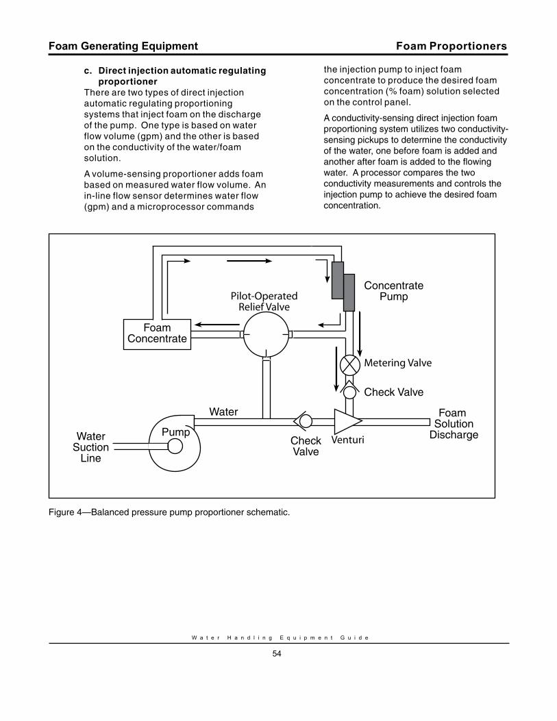
W a t e r H a n d l i n g E q u i p m e n t G u i d e
54
Foam Generating Equipment
c. Direct injection automatic regulating proportionerThere are two types of direct injection automatic regulating proportioning systems that inject foam on the discharge of the pump. One type is based on water flow volume (gpm) and the other is based on the conductivity of the water/foam solution.
A volume-sensing proportioner adds foam based on measured water flow volume. An in-line flow sensor determines water flow (gpm) and a microprocessor commands
the injection pump to inject foam concentrate to produce the desired foam concentration (% foam) solution selected on the control panel.
A conductivity-sensing direct injection foam proportioning system utilizes two conductivity-sensing pickups to determine the conductivity of the water, one before foam is added and another after foam is added to the flowing water. A processor compares the two conductivity measurements and controls the injection pump to achieve the desired foam concentration.
Foam Proportioners
PumpWaterSuction
Line
Check Valve
Foam Solution
DischargeCheckValve
ConcentratePump
Water
FoamConcentrate
Metering Valve
Venturi
Pilot-OperatedRelief Valve
Figure 4—Balanced pressure pump proportioner schematic.
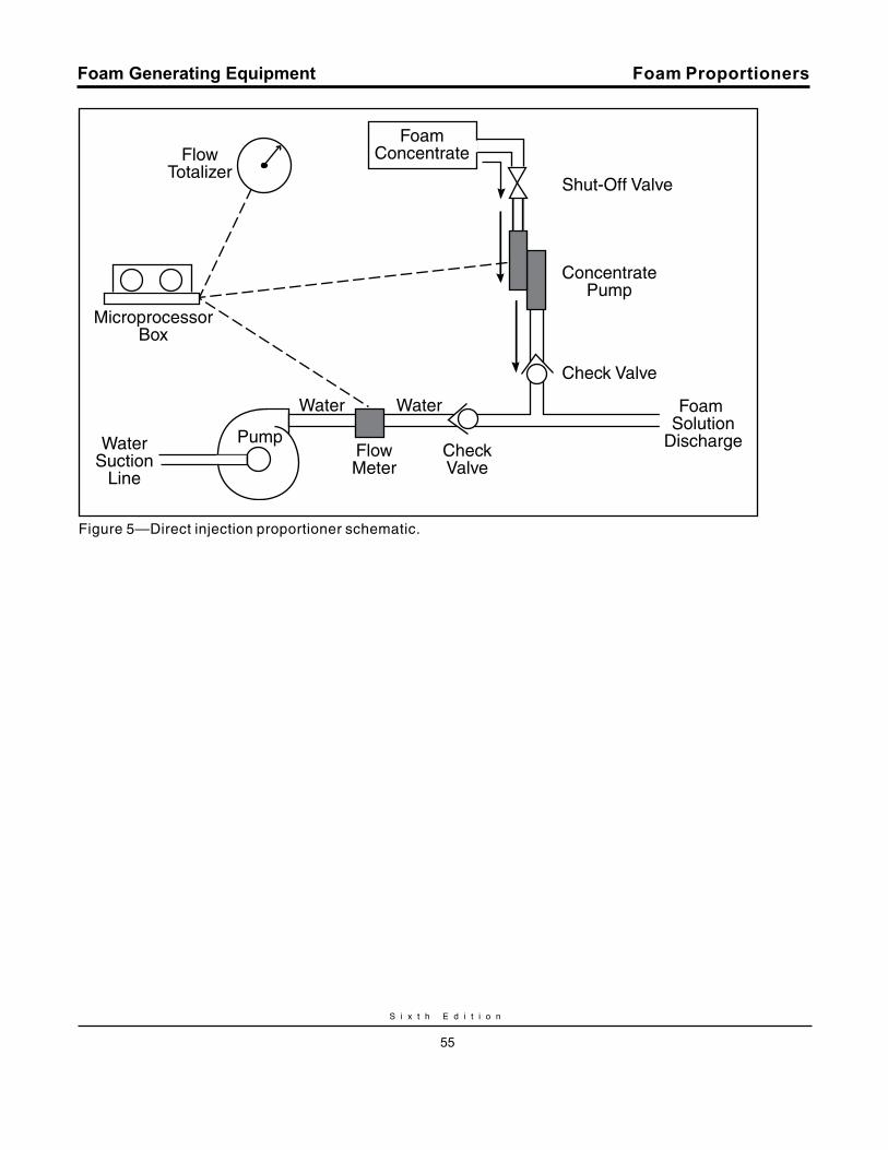
S i x t h E d i t i o n
55
Foam Generating Equipment
PumpWaterSuction
Line
Shut-Off Valve
Check Valve
Foam Solution
Discharge
FoamConcentrate
CheckValve
ConcentratePump
FlowMeter
Water Water
MicroprocessorBox
FlowTotalizer
Figure 5—Direct injection proportioner schematic.
Foam Proportioners
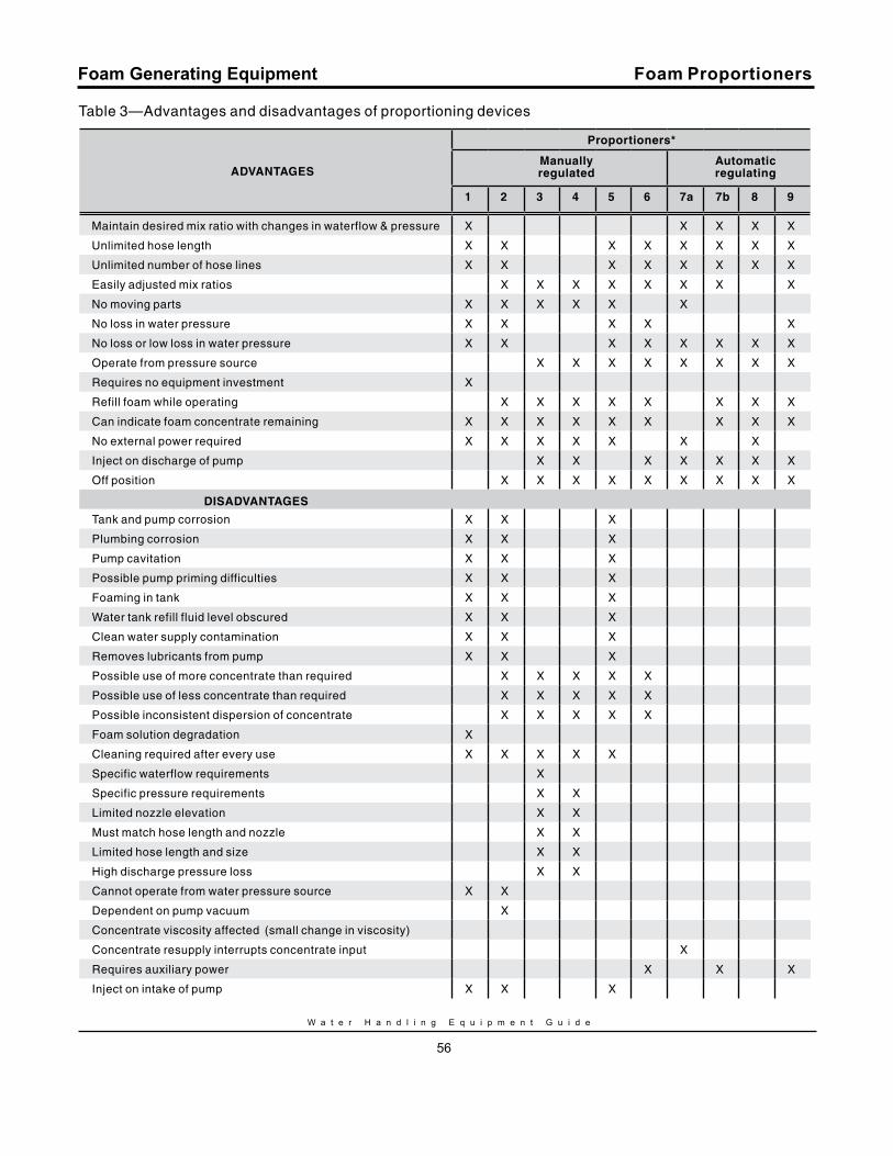
W a t e r H a n d l i n g E q u i p m e n t G u i d e
56
Foam Generating Equipment Foam Proportioners
Table 3—Advantages and disadvantages of proportioning devices
ADvANTAGES
Proportioners*
manuallyregulated
Automaticregulating
1 2 3 4 5 6 7a 7b 8 9
Maintain desired mix ratio with changes in waterflow & pressure X X X X X
Unlimited hose length X X X X X X X X
Unlimited number of hose lines X X X X X X X X
Easily adjusted mix ratios X X X X X X X X
No moving parts X X X X X X
No loss in water pressure X X X X X
No loss or low loss in water pressure X X X X X X X X
Operate from pressure source X X X X X X X X
Requires no equipment investment X
Refill foam while operating X X X X X X X X
Can indicate foam concentrate remaining X X X X X X X X X
No external power required X X X X X X X
Inject on discharge of pump X X X X X X X
Off position X X X X X X X X X
DISADvANTAGES
Tank and pump corrosion X X X
Plumbing corrosion X X X
Pump cavitation X X X
Possible pump priming difficulties X X X
Foaming in tank X X X
Water tank refill fluid level obscured X X X
Clean water supply contamination X X X
Removes lubricants from pump X X X
Possible use of more concentrate than required X X X X X
Possible use of less concentrate than required X X X X X
Possible inconsistent dispersion of concentrate X X X X X
Foam solution degradation X
Cleaning required after every use X X X X X
Specific waterflow requirements X
Specific pressure requirements X X
Limited nozzle elevation X X
Must match hose length and nozzle X X
Limited hose length and size X X
High discharge pressure loss X X
Cannot operate from water pressure source X X
Dependent on pump vacuum X
Concentrate viscosity affected (small change in viscosity)
Concentrate resupply interrupts concentrate input X
Requires auxiliary power X X X
Inject on intake of pump X X X
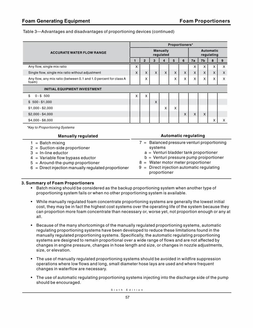
S i x t h E d i t i o n
57
Foam Generating Equipment
Table 3—Advantages and disadvantages of proportioning devices (continued)
Proportioners*
ACCurATE WATEr FLOW rANGEmanually regulated
Automatic regulating
1 2 3 4 5 6 7a 7b 8 9
Any flow, single mix ratio X X X X X
Single flow, single mix ratio without adjustment X X X X X X X X X X
Any flow, any mix ratio (between 0.1 and 1.0 percent for class A foam)
X X X X X X X
INITIAL EquIPmENT INvESTmENT
$ 0 - $ 500 X X
$ 500 - $1,000 X
$1,000 - $2,000 X X
$2,000 - $4,000 X X X
$4,000 - $8,000 X X
*Key to Proportioning Systems
Foam Proportioners
manually regulated
1 = Batch mixing 2 = Suction-side proportioner 3 = In-line eductor 4 = Variable flow bypass eductor 5 = Around-the-pump proportioner 6 = Direct injection manually regulated proportioner
Automatic regulating
7 = Balanced pressure venturi proportioning systems a = Venturi bladder tank proportioner b = Venturi pressure pump proiportioner8 = Water motor meter proportioner
9 = Direct injection automatic regulating proportioner
3. Summary of Foam Proportioners• Batch mixing should be considered as the backup proportioning system when another type of
proportioning system fails or when no other proportioning system is available.
• While manually regulated foam concentrate proportioning systems are generally the lowest initial cost, they may be in fact the highest cost systems over the operating life of the system because they can proportion more foam concentrate than necessary or, worse yet, not proportion enough or any at all.
• Because of the many shortcomings of the manually regulated proportioning systems, automatic regulating proportioning systems have been developed to reduce these limitations found in the manually regulated proportioning systems. Specifically, the automatic regulating proportioning systems are designed to remain proportional over a wide range of flows and are not affected by changes in engine pressure, changes in hose length and size, or changes in nozzle adjustments, size, or elevation.
• The use of manually regulated proportioning systems should be avoided in wildfire suppression operations where low flows and long, small diameter hose lays are used and where frequent changes in waterflow are necessary.
• The use of automatic regulating proportioning systems injecting into the discharge side of the pump should be encouraged.
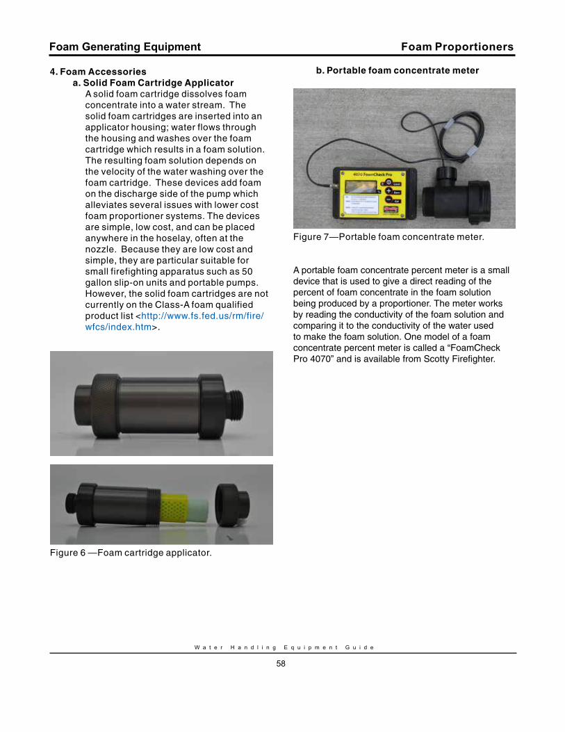
W a t e r H a n d l i n g E q u i p m e n t G u i d e
58
Foam Generating Equipment
4. Foam Accessoriesa. Solid Foam Cartridge Applicator
A solid foam cartridge dissolves foam concentrate into a water stream. The solid foam cartridges are inserted into an applicator housing; water flows through the housing and washes over the foam cartridge which results in a foam solution. The resulting foam solution depends on the velocity of the water washing over the foam cartridge. These devices add foam on the discharge side of the pump which alleviates several issues with lower cost foam proportioner systems. The devices are simple, low cost, and can be placed anywhere in the hoselay, often at the nozzle. Because they are low cost and simple, they are particular suitable for small firefighting apparatus such as 50 gallon slip-on units and portable pumps. However, the solid foam cartridges are not currently on the Class-A foam qualified product list <http://www.fs.fed.us/rm/fire/wfcs/index.htm>.
Figure 6 —Foam cartridge applicator.
b. Portable foam concentrate meter
Figure 7—Portable foam concentrate meter.
A portable foam concentrate percent meter is a small device that is used to give a direct reading of the percent of foam concentrate in the foam solution being produced by a proportioner. The meter works by reading the conductivity of the foam solution and comparing it to the conductivity of the water used to make the foam solution. One model of a foam concentrate percent meter is called a “FoamCheck Pro 4070” and is available from Scotty Firefighter.
Foam Proportioners
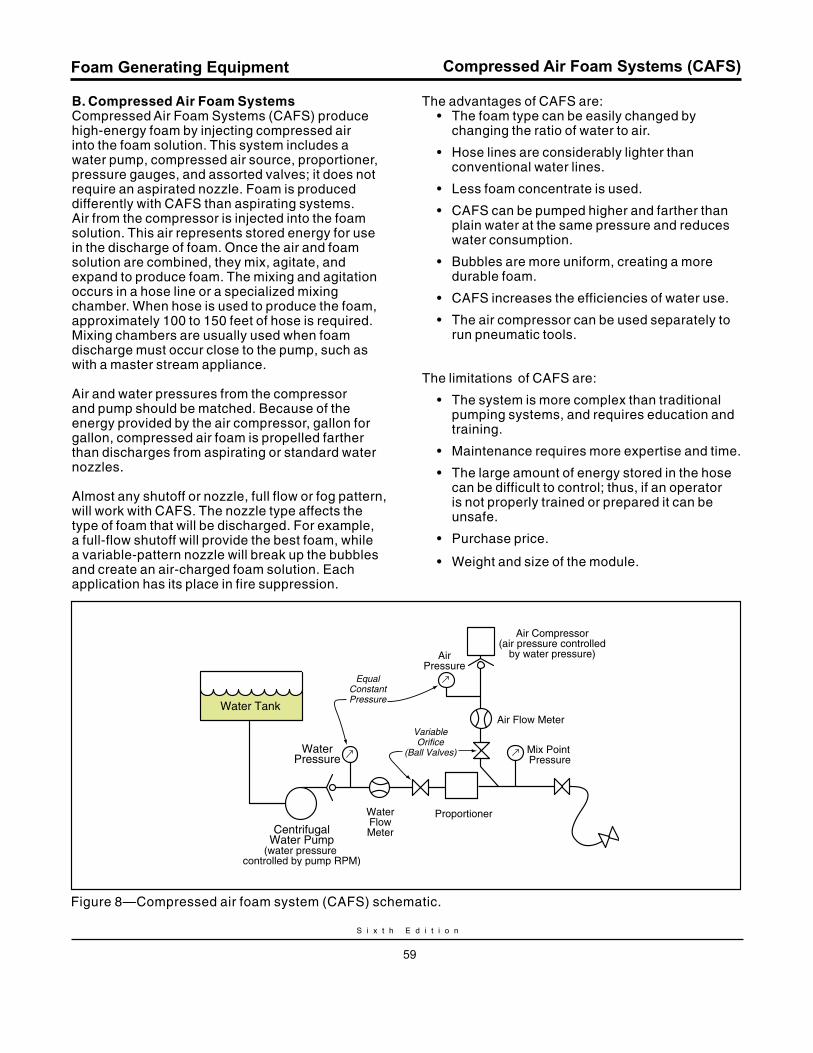
S i x t h E d i t i o n
59
Foam Generating Equipment
B. Compressed Air Foam Systems Compressed Air Foam Systems (CAFS) produce high-energy foam by injecting compressed air into the foam solution. This system includes a water pump, compressed air source, proportioner, pressure gauges, and assorted valves; it does not require an aspirated nozzle. Foam is produced differently with CAFS than aspirating systems. Air from the compressor is injected into the foam solution. This air represents stored energy for use in the discharge of foam. Once the air and foam solution are combined, they mix, agitate, and expand to produce foam. The mixing and agitation occurs in a hose line or a specialized mixing chamber. When hose is used to produce the foam, approximately 100 to 150 feet of hose is required. Mixing chambers are usually used when foam discharge must occur close to the pump, such as with a master stream appliance.
Air and water pressures from the compressor and pump should be matched. Because of the energy provided by the air compressor, gallon for gallon, compressed air foam is propelled farther than discharges from aspirating or standard water nozzles.
Almost any shutoff or nozzle, full flow or fog pattern, will work with CAFS. The nozzle type affects the type of foam that will be discharged. For example, a full-flow shutoff will provide the best foam, while a variable-pattern nozzle will break up the bubbles and create an air-charged foam solution. Each application has its place in fire suppression.
The advantages of CAFS are:• The foam type can be easily changed by
changing the ratio of water to air.
• Hose lines are considerably lighter than conventional water lines.
• Less foam concentrate is used.
• CAFS can be pumped higher and farther than plain water at the same pressure and reduces water consumption.
• Bubbles are more uniform, creating a more durable foam.
• CAFS increases the efficiencies of water use.
• The air compressor can be used separately to run pneumatic tools.
The limitations of CAFS are:
• The system is more complex than traditional pumping systems, and requires education and training.
• Maintenance requires more expertise and time.
• The large amount of energy stored in the hose can be difficult to control; thus, if an operator is not properly trained or prepared it can be unsafe.
• Purchase price.
• Weight and size of the module.
Compressed Air Foam Systems (CAFS)
Water Tank
WaterPressure
CentrifugalWater Pump
(water pressure controlled by pump RPM)
WaterFlowMeter
Proportioner
Mix Point Pressure
Air Flow Meter
AirPressure
Air Compressor(air pressure controlled
by water pressure)
EqualConstantPressure
VariableOrifice
(Ball Valves)
Figure 8—Compressed air foam system (CAFS) schematic.
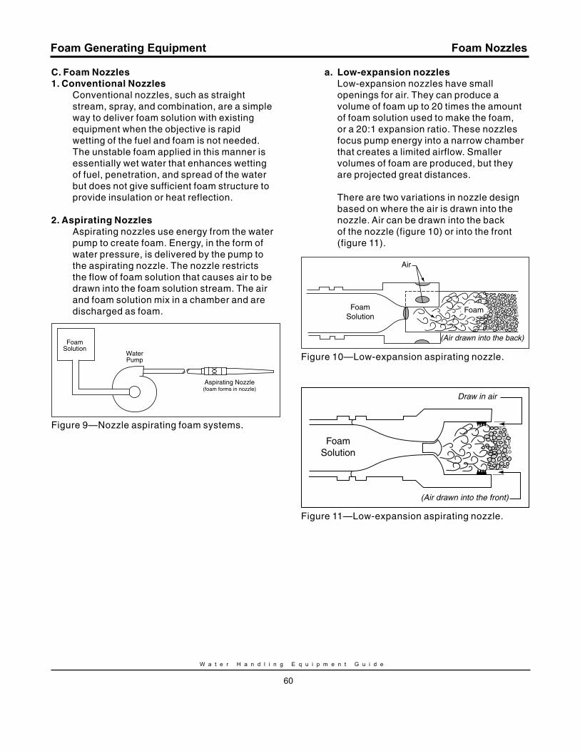
W a t e r H a n d l i n g E q u i p m e n t G u i d e
60
Foam Generating Equipment
C. Foam Nozzles1. Conventional Nozzles
Conventional nozzles, such as straight stream, spray, and combination, are a simple way to deliver foam solution with existing equipment when the objective is rapid wetting of the fuel and foam is not needed. The unstable foam applied in this manner is essentially wet water that enhances wetting of fuel, penetration, and spread of the water but does not give sufficient foam structure to provide insulation or heat reflection.
2. Aspirating NozzlesAspirating nozzles use energy from the water pump to create foam. Energy, in the form of water pressure, is delivered by the pump to the aspirating nozzle. The nozzle restricts the flow of foam solution that causes air to be drawn into the foam solution stream. The air and foam solution mix in a chamber and are discharged as foam.
FoamSolution
WaterPump
Aspirating Nozzle(foam forms in nozzle)
Figure 9—Nozzle aspirating foam systems.
a. Low-expansion nozzlesLow-expansion nozzles have small openings for air. They can produce a volume of foam up to 20 times the amount of foam solution used to make the foam, or a 20:1 expansion ratio. These nozzles focus pump energy into a narrow chamber that creates a limited airflow. Smaller volumes of foam are produced, but they are projected great distances.
There are two variations in nozzle design based on where the air is drawn into the nozzle. Air can be drawn into the back of the nozzle (figure 10) or into the front (figure 11).
FoamSolution
Air
Foam
(Air drawn into the back)
Figure 10—Low-expansion aspirating nozzle.
FoamSolution
(Air drawn into the front)
Draw in air
Figure 11—Low-expansion aspirating nozzle.
Foam Nozzles
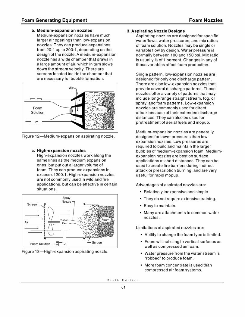
S i x t h E d i t i o n
61
Foam Generating Equipment
b. medium-expansion nozzlesMedium-expansion nozzles have much larger air openings than low-expansion nozzles. They can produce expansions from 20:1 up to 200:1, depending on the design of the nozzle. A medium-expansion nozzle has a wide chamber that draws in a large amount of air, which in turn slows down the stream velocity. There are screens located inside the chamber that are necessary for bubble formation.
Air
FoamSolution
Foam
Figure 12—Medium-expansion aspirating nozzle.
c. High-expansion nozzlesHigh-expansion nozzles work along the same lines as the medium expansion ones, but put out a larger volume of foam. They can produce expansions in excess of 200:1. High-expansion nozzles are not commonly used in wildland fire applications, but can be effective in certain situations.
Air
Foam Solution
FoamTurbanFan
SprayNozzle
Screen
Screen
Figure 13—High-expansion aspirating nozzle.
3. Aspirating Nozzle DesignsAspirating nozzles are designed for specific waterflows, water pressures, and mix ratios of foam solution. Nozzles may be single or variable flow by design. Water pressure is normally between 100 and 150 psi. Mix ratio is usually ½ of 1 percent. Changes in any of these variables affect foam production.
Single pattern, low-expansion nozzles are designed for only one discharge pattern. There are also low-expansion nozzles that provide several discharge patterns. These nozzles offer a variety of patterns that may include long-range straight stream, fog, or spray, and foam patterns. Low-expansion nozzles are commonly used for direct attack because of their extended discharge distances. They can also be used for pretreatment of aerial fuels and mopup.
Medium-expansion nozzles are generally designed for lower pressures than low-expansion nozzles. Low pressures are required to build and maintain the larger bubbles of medium-expansion foam. Medium-expansion nozzles are best on surface applications at short distances. They can be used to create fire barriers during indirect attack or prescription burning, and are very useful for rapid mopup.
Advantages of aspirated nozzles are:
• Relatively inexpensive and simple.
• They do not require extensive training.
• Easy to maintain.
• Many are attachments to common water nozzles.
Limitations of aspirated nozzles are:
• Ability to change the foam type is limited.
• Foam will not cling to vertical surfaces as well as compressed air foam.
• Water pressure from the water stream is “robbed” to produce foam.
• More foam concentrate is used than compressed air foam systems.
Foam Nozzles


CH
AP
TE
R I
IIW
AT
ER
D
EL
IV
ER
Y
CO
NP
ON
EN
TS


S i x t h E d i t i o n
65
Water Delivery Components and Accessories
III. WATEr DELIvEry COmPONENTS AND ACCESSOrIES
A. Hose1. General
Firehose provides the essential means of transporting water from a stream, lake, hydrant, or engine to the fire. The hose selected must be abrasion-resistant and withstand the necessary pressures involved, yet be flexible and lightweight enough to carry. Most hose in use is purchased by the General Service Administration (GSA) under specifications developed by the USDA Forest Service. Wildland firefighting agencies purchase approximately 3 million feet of small diameter (1 and 1½ inch) firehose annually.
Appendix D of this guide provides service test information for fire hose. The care and maintenance of firehose is also described in NFPA 1962. A review of the appropriate acronyms and definitions will be helpful when using this section on firehose (see appendixes I and J).
2. Design CriteriaThe nominal outside diameters of all jacketed hose furnished under USDA Forest Service specifications are controlled. A saving thereby results, since coupling bowls for all jacketed hoses are identical and interchangeable. The outside diameter (OD) for 1-inch hose is 1¼ inches and for 1½-inch hose, it is 1¾ inches. In general fire department practice, the inside diameter (ID) is controlled and the OD varies with the jacket thickness, the type of liner, and other variables.
Jacketed fire hose elongates when pressurized. Most hose also twists under working pressure, and the direction of twist must tighten, not loosen, the couplings. Jacketed hose also tends to warp and rise. Fire hose is hydrostatically tested in accordance with the testing procedure as required by the procurement contract, if procured under USDA Forest Service specifications.
3. Hose Typesa. Cotton jacket rubber lined
Standard cotton jacket hose has a working pressure of 250 psi. Cotton is more resistant to heat and flame damage than synthetic fibers. Hot embers, however, may cause small pinholes. Cotton-jacketed hose in most agencies has been replaced with lightweight, synthetic hose (see b, c, and d).
Type: Single-jacket fabric, elastomer lined.
Construction and material: The jacket consists of woven cotton yarn. The liner is petroleum-based thermoplastic polyester elastomer with a smooth inner surface. The jacket and liner are bonded together.
Flow rate: Friction loss relative to hose diameters is basically the same as the cotton-synthetic lined hose. Slight differences may be due to type of lining and roughness of inside surface of the lining.
Weight: 1-inch has maximum weight of 28 lb/100 ft; 1½ inch 33 lb/100 ft.
Written material: Federal specification A-A-59226 available from General Supply Administration (GSA).
b. Cotton-synthetic lined This hose is used where higher working pressures are required. It has a working pressure of 300 psi. The cotton fibers run lengthwise (warp), and the synthetic fillers run crosswise, to form the weave. This combination makes a lighter, stronger jacket, but is subject to heat and flame damage. Grade A liners, capable of withstanding long periods of weather aging and high ozone conditions without checking or cracking are also available. Combination fabric jackets come in both 1- and 1½ inch diameters, and are usually furnished in 50- and 100-foot lengths.
Type: Single jacket fabric, elastomer lined.
Hose
W a t e r H a n d l i n g E q u i p m e n t G u i d e
66
Water Delivery Components and Accessories
Construction and materials: The jacket consists of woven cotton and polyester filler yarn. The liner is a petroleum-based thermoplastic polyester elastomer with a smooth inner surface. The jacket and liner are bonded together.
Written material: Specification 5100-186 is available from: USDA Forest Service Technology and Development Center 444 East Bonita Avenue San Dimas, CA 91773 Phone: 909–599–1267
c. Synthetic lightweight lined type I hose
Type: Single jacket fabric, lined, mildew resistant, with a working pressure of 300 psi.
Construction and materials: The jacket consists of 100 percent filament polyester warp and filler yarns. The liner consists of synthetic rubber or a combination of other synthetic material with a smooth inner surface. The lining is fully bonded to the jacket.
Available from GSA:
100 foot1 inch (9.5 lb/100 feet*)NSN 4210-01-166-8122
100 foot1½ inch (13.0 lb/100 feet*)NSN 4210-01-165-6597
(*Weight is with the couplings.)
Written material: Specification 5100-187 is available from:
USDA Forest Service Technology and Development Center 444 East Bonita Avenue San Dimas, CA 91773 Phone: 909–599–1267
d. Abrasion resistant synthetic lightweight lined type II hose
Type: Lined, woven single-jacket, abrasion, and mildew resistant, with a working pressure of 300 psi.
Construction and materials: The jacket is a twill pattern and consistes of spun polyester warp yarn and filament polyester filler (weft) yarn to enhance abrasion resistance. The liner is composed of natural or synthetic rubber compound or thermoplastic. The hose is mildew resistant.
Available from GSA:
100 foot1 inch (10.0 lb/100 feet*)NSN 4210-01-526-3000
100 foot1½ inch (16.00 lb/100 feet*)
NSN 4210-01-526-2977(*Weight is with the couplings.)
Written materials: Specification 5100-187 is available from:
USDA Forest Service Technology and Development Center 444 East Bonita Avenue San Dimas, CA 91773 Phone: 909–599–1267
Hose
S i x t h E d i t i o n
67
Water Delivery Components and Accessories
e. Double-jacketed hoseDouble-jacketed hose is heavier and more costly than single-jacketed hose. In practice, some engines carry one or two lengths of double-jacketed hose for the first lengths in the lay to reduce excessive water losses from bursts closer to the engine.
Type: Double-jacketed, rubber-lined, with a working pressure of 400 psi.
Construction and materials: There are two jackets constructed of 100 percent spun polyester yarn. The liner is a petroleum-based thermoplastic polyester elastomer with a smooth inner surface. The inside jacket and liner are bonded together.
Flow rate: Friction loss relative to hose diameters is basically the same as the cotton-synthetic lined hose. Slight differences may be due to the type of lining and roughness of the inside surface of the lining.
Weight: Weights of hoses are as follows (weights may vary depending on tolerance):
1½ inch 38 lb/100 ft; 2½ inch 68 lb/100 ft.
Written material: Federal specification A-A-59226 is available from General Services Administration (GSA).
f. rubber lined, braided high pressure hose Rubber-lined, rubber-covered, high-pressure hose is used as “hardline” on engine live reels. Current Forest Service specifications require a heavy-duty, noncollapsible water hose of braided and molded construction. This hose is designed for use on hose reels and hot fire lines with little possibility of damage. The hose can be wiped off with a dry rag after use. Abrasion resistance is high and the exterior covering is not readily damaged by the usual solvents. High-pressure hose (¾ inch ID) is available in 50-foot coupled lengths. This category also includes booster hose, which is not included in Specification 5100-185.
Type: Compound rubber cover, multiple plies yarn reinforcement, and rubber-inner lining, with a working pressure of 600 psi. Booster hose has a working pressure of 800 psi.
Construction and materials: Multiple layers of braided or knit piles of cotton or synthetic yarn are embedded in rubber compound cover. The inner lining consists of a tube of rubber. The lining and cover are bonded together.
Available from GSA:
50 foot¾ inch ID (28 lb/50 feet)NSN 4210-00-595-1838
Written material: Specification 5100-185 is available from:
USDA Forest Service Technology and Development Center 444 East Bonita Avenue San Dimas, CA 91773 Phone: 909–599–1267
g. Woven fabric hardline hose This hose is used as an initial attack hose and is available in ¾-inch and 1-inch diameter and in 50-, 100-, and 150-foot lengths. The lightweight construction includes a woven fabric jacket, a plastic helical reinforcement component, and a coating to improve abrasion resistance. It handles like a lay-flat hose yet performs like a rigid reel hose and provides water repellency, abrasion, oil and chemical resistance.
Type: Semi-rigid hardline hose, with a working pressure of 300 psi. Construction and materials: Lightweight woven fabric of spun polyester warp yarns with plastic helical reinforcement component and elastomer extruded tubing.
Weight: Uncoupled ¾-inch (lb/100 feet) = 16; 1-inch (lb/100 feet) = 21.
Hose
W a t e r H a n d l i n g E q u i p m e n t G u i d e
68
Water Delivery Components and Accessories
Available: Fire equipment suppliers.
50 foot1 inch
10.5 lb/50 feet (uncoupled)Commercially available
100 foot1 inch
21.0 lb/100 feet (uncoupled)Commercially available
Written material: Hardline Hose Comparison Study, Tech Tip 0251 1307—SDTDC, is available from:
USDA Forest Service Technology and Development Center 444 East Bonita Avenue San Dimas, CA 91773 Phone: 909–599–1267
h. relay-supply large diameter hose A single-jacket relay-supply hose has seen increasing use in the United States by fire departments. The single-jacket, made of all-synthetic fibers, is coated inside and out with a thin protective coating. The hose is available in 3½- , 4-, 4½- , 5-, and 6-inch diameters, and is often coupled with a lightweight aluminum alloy quick-connect coupling.
The hose is intended for supply line use only from a water source to the engine. It is not intended to move large volumes of water long distances, and never to a manifold or on the discharge side of an engine. Limited use has been made of this hose at airtanker bases for loading. Usually this hose performs poorly when subjected to a kink test.
i. Garden hose Type: Single jacket, lined. Operating pressure is 200 psi.
Construction and materials: 100 percent synthetic, woven jacket with liner.
Available from GSA:
50 footNSN 4210-01-167-1061
j. Suction hose, heavy dutyHard-suction draft hose is used on all engines and with all portable pumps. Under Forest Service Specification 5100-184, the hose is made of a natural or synthetic-rubber tube; a jacket consisting of cotton warp yarns or other suitable yarns interwoven with a helix or helixes of round spring-temper wire and fillers of yarn; and a synthetic-rubber outer covering. The coupled hose is designed for a hydrostatic-proof pressure test of 100 psi and a vacuum of 25 inches of mercury without internal blistering, undue distortion, or leakage. Suction hoses are usually furnished in 8- and 10-foot lengths. Soft suction is now widely accepted in fire department practice where engines connect directly to hydrants. The weight savings and flexibility of these 2½- to 6-inch diameters are significant factors.
Available from GSA:
8 foot1½ inch
10.5 lb/8 footNSN 4210-00-889-1774
Hose
S i x t h E d i t i o n
69
Water Delivery Components and Accessories
10 foot 1½ inch
12.9 lb/10 footNSN 4210-00-889-1775
8 foot2½ inch
20.4 lb/8 footCommercially available
10 foot2½ inch
25.0 lb/10 footCommercially available
Written material: Specification 5100-184 is available from:
USDA Forest Service Technology and Development Center 444 East Bonita Avenue San Dimas, CA 91773 Phone: 909–599–1267
k. Suction hose, lightweightNew technology presents a lighter construction with comparable performance, capable of holding a vacuum of 25 inches of mercury and a hydrostatic proof pressure higher than the rubber draft hose, at a proof of 600 psi. It has an encapsulation treatment for enhanced abrasion resistance and the manufacturer claims an increased resistance to acids, oils, chemicals, and salt water.
Type: Woven fabric jacket suction hose
Construction and materials: Woven fabric jacket and a plastic helical reinforcement component have an encapsulation treatment. The extruded tubing is an ozone resistant, and age resistant EPDM extruded elastomer.
Weight: 1½ inch 45 lb/100 foot; 2 inch 50 lb/100 foot.
Available: Fire equipment suppliers.
Written materials: Draft Hose Comparison Study, Tech Tip 0351 1309, March 2003 SDTDC, is available from:
USDA Forest Service Technology and Development Center 444 East Bonita Avenue San Dimas, CA 91773 Phone: 909–599–1267
l. Cotton-synthetic self-protecting (weeping) hosesWeeping hose is used as replacement for linen (unlined) hose. Cotton-synthetic weeping hose is lightweight, treated to prevent mildew, and designed for uniform weeping, fast drying time, and high-heat resistance. Synthetic hose/weeping hose is designed for high working pressures, high temperatures, and abrasion-resistance; they may be lined for antifriction and hose-weep control to protect the hose.
Hose
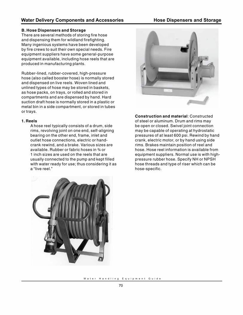
W a t e r H a n d l i n g E q u i p m e n t G u i d e
70
Water Delivery Components and Accessories
B. Hose Dispensers and StorageThere are several methods of storing fire hose and dispensing them for wildland firefighting. Many ingenious systems have been developed by fire crews to suit their own special needs. Fire equipment suppliers have some general-purpose equipment available, including hose reels that are produced in manufacturing plants.
Rubber-lined, rubber-covered, high-pressure hose (also called booster hose) is normally stored and dispensed on live reels. Woven lined and unlined types of hose may be stored in baskets, as hose packs, on trays, or rolled and stored in compartments and are dispensed by hand. Hard suction draft hose is normally stored in a plastic or metal bin in a side compartment, or stored in tubes or trays.
1. reelsA hose reel typically consists of a drum, side rims, revolving joint on one end, self-aligning bearing on the other end, frame, inlet and outlet hose connections, electric or hand-crank rewind, and a brake. Various sizes are available. Rubber or fabric hoses in ¾ or 1 inch sizes are used on the reels that are usually connected to the pump and kept filled with water ready for use; thus considering it as a “live reel.”
Construction and material: Constructed of steel or aluminum. Drum and rims may be open or closed. Swivel joint connection may be capable of operating at hydrostatic pressures of at least 600 psi. Rewind by hand crank, electric motor, or by hand using side rims. Brakes maintain position of reel and hose. Hose reel information is available from equipment suppliers. Normal use is with high-pressure rubber hose. Specify NH or NPSH hose threads and type of riser which can be hose-specific.
Hose Dispensers and Storage
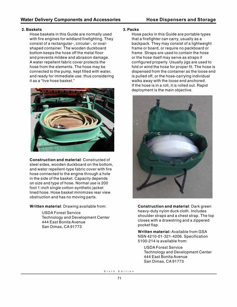
S i x t h E d i t i o n
71
Water Delivery Components and Accessories
2. BasketsHose baskets in this Guide are normally used with fire engines for wildland firefighting. They consist of a rectangular-, circular-, or oval-shaped container. The wooden duckboard bottom keeps the hose off the metal floor and prevents mildew and abrasion damage. A water repellent fabric cover protects the hose from the elements. The hose may be connected to the pump, kept filled with water, and ready for immediate use; thus considering it as a “live hose basket.”
Construction and material: Constructed of steel sides, wooden duckboard on the bottom, and water repellent-type fabric cover with fire hose connected to the engine through a hole in the side of the basket. Capacity depends on size and type of hose. Normal use is 200 foot 1-inch single cotton-synthetic jacket lined hose. Hose basket minimizes rear view obstruction and has no moving parts.
Written material: Drawing available from:
USDA Forest Service Technology and Development Center 444 East Bonita Avenue San Dimas, CA 91773
3. PacksHose packs in this Guide are portable types that a firefighter can carry, usually as a backpack. They may consist of a lightweight frame or board, or require no packboard or frame. Straps are used to contain the hose or the hose itself may serve as straps if configured properly. Usually jigs are used to fold or wind the hose for proper fit. The hose is dispensed from the container as the loose end is pulled off, or the hose-carrying individual walks away with the loose end anchored. If the hose is in a roll, it is rolled out. Rapid deployment is the main objective.
a. Forester hose packsack
Construction and material: Dark green heavy-duty nylon duck cloth. Includes shoulder straps and a chest strap. The top closes with a drawstring and a zippered pocket flap.
Written material: Available from GSA NSN 4210-01-321-4206. Specification 5100-214 is available from:
USDA Forest Service Technology and Development Center 444 East Bonita Avenue San Dimas, CA 91773
Hose Dispensers and Storage
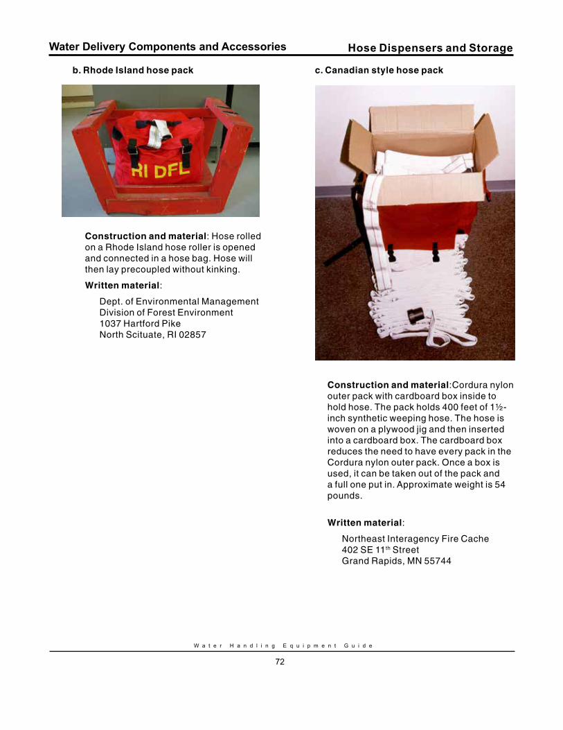
W a t e r H a n d l i n g E q u i p m e n t G u i d e
72
Water Delivery Components and Accessories
b. rhode Island hose pack
Construction and material: Hose rolled on a Rhode Island hose roller is opened and connected in a hose bag. Hose will then lay precoupled without kinking.
Written material:
Dept. of Environmental Management Division of Forest Environment 1037 Hartford Pike North Scituate, RI 02857
c. Canadian style hose pack
Construction and material:Cordura nylon outer pack with cardboard box inside to hold hose. The pack holds 400 feet of 1½-inch synthetic weeping hose. The hose is woven on a plywood jig and then inserted into a cardboard box. The cardboard box reduces the need to have every pack in the Cordura nylon outer pack. Once a box is used, it can be taken out of the pack and a full one put in. Approximate weight is 54 pounds.
Written material:
Northeast Interagency Fire Cache 402 SE 11th Street Grand Rapids, MN 55744
Hose Dispensers and Storage
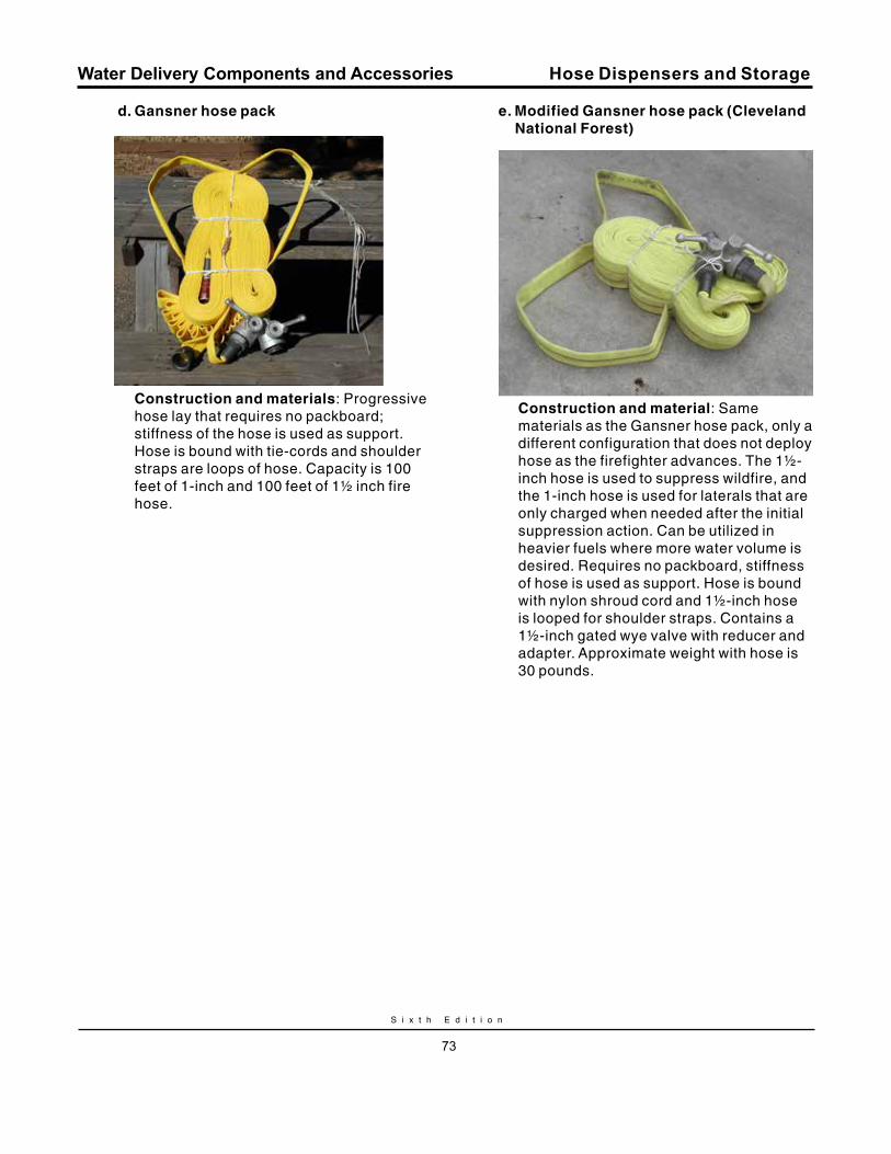
S i x t h E d i t i o n
73
Water Delivery Components and Accessories
d. Gansner hose pack
Construction and materials: Progressive hose lay that requires no packboard; stiffness of the hose is used as support. Hose is bound with tie-cords and shoulder straps are loops of hose. Capacity is 100 feet of 1-inch and 100 feet of 1½ inch fire hose.
e. modified Gansner hose pack (Cleveland National Forest)
Construction and material: Same materials as the Gansner hose pack, only a different configuration that does not deploy hose as the firefighter advances. The 1½- inch hose is used to suppress wildfire, and the 1-inch hose is used for laterals that are only charged when needed after the initial suppression action. Can be utilized in heavier fuels where more water volume is desired. Requires no packboard, stiffness of hose is used as support. Hose is bound with nylon shroud cord and 1½-inch hose is looped for shoulder straps. Contains a 1½-inch gated wye valve with reducer and adapter. Approximate weight with hose is 30 pounds.
Hose Dispensers and Storage
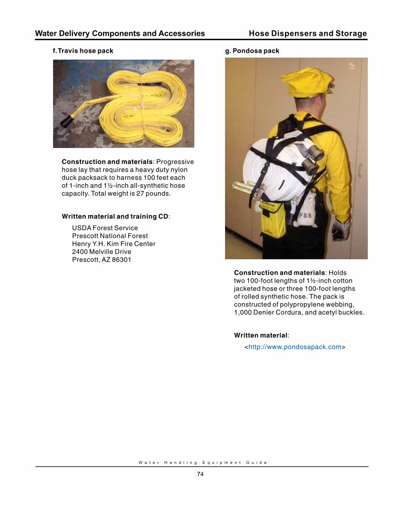
W a t e r H a n d l i n g E q u i p m e n t G u i d e
74
Water Delivery Components and Accessories
f. Travis hose pack
Construction and materials: Progressive hose lay that requires a heavy duty nylon duck packsack to harness 100 feet each of 1-inch and 1½-inch all-synthetic hose capacity. Total weight is 27 pounds.
Written material and training CD:
USDA Forest Service Prescott National Forest Henry Y.H. Kim Fire Center 2400 Melville Drive Prescott, AZ 86301
Hose Dispensers and Storage
g. Pondosa pack
Construction and materials: Holds two 100-foot lengths of 1½-inch cotton jacketed hose or three 100-foot lengths of rolled synthetic hose. The pack is constructed of polypropylene webbing, 1,000 Denier Cordura, and acetyl buckles.
Written material:
<http://www.pondosapack.com>
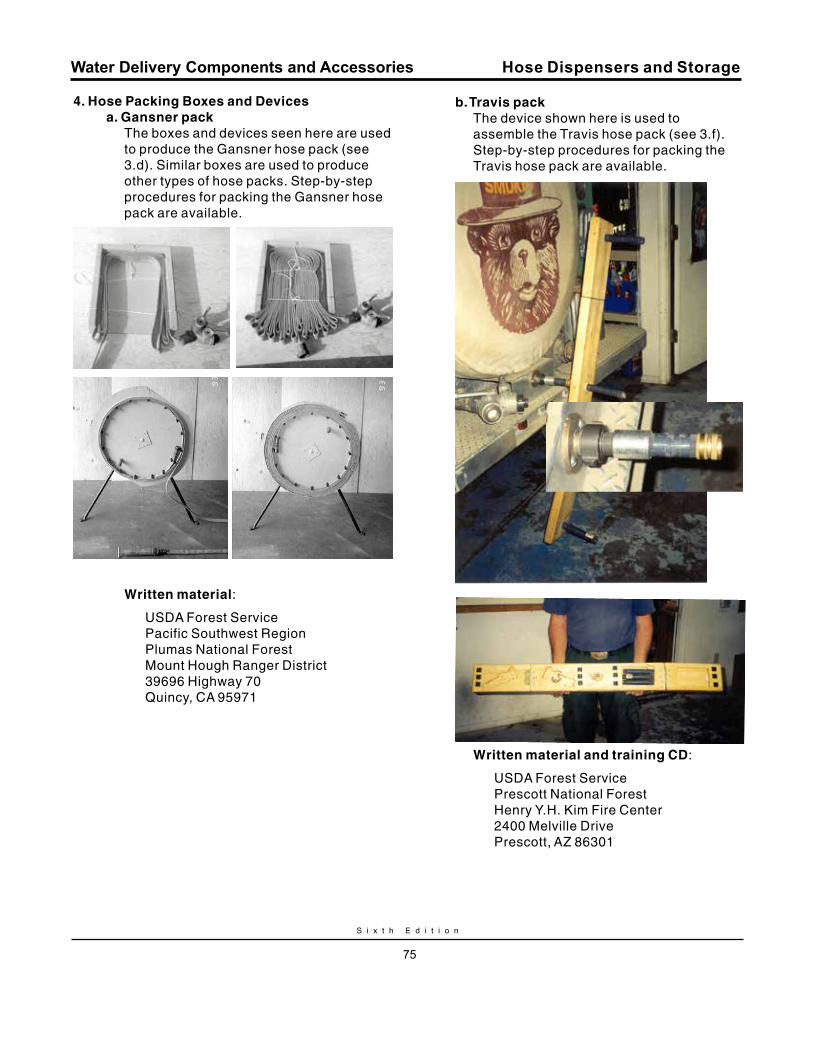
S i x t h E d i t i o n
75
Water Delivery Components and Accessories
4. Hose Packing Boxes and Devicesa. Gansner pack
The boxes and devices seen here are used to produce the Gansner hose pack (see 3.d). Similar boxes are used to produce other types of hose packs. Step-by-step procedures for packing the Gansner hose pack are available.
Written material:
USDA Forest Service Pacific Southwest Region Plumas National Forest Mount Hough Ranger District 39696 Highway 70 Quincy, CA 95971
Hose Dispensers and Storage
b. Travis packThe device shown here is used to assemble the Travis hose pack (see 3.f). Step-by-step procedures for packing the Travis hose pack are available.
Written material and training CD:
USDA Forest Service Prescott National Forest Henry Y.H. Kim Fire Center 2400 Melville Drive Prescott, AZ 86301
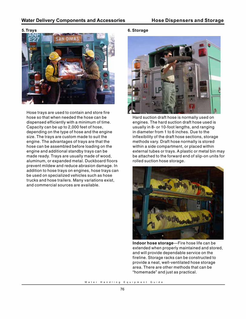
W a t e r H a n d l i n g E q u i p m e n t G u i d e
76
Water Delivery Components and Accessories
5. Trays
Hose trays are used to contain and store fire hose so that when needed the hose can be dispensed efficiently with a minimum of time. Capacity can be up to 2,000 feet of hose, depending on the type of hose and the engine size. The trays are custom made to suit the engine. The advantages of trays are that the hose can be assembled before loading on the engine and additional standby trays can be made ready. Trays are usually made of wood, aluminum, or expanded metal. Duckboard floors prevent mildew and reduce abrasion damage. In addition to hose trays on engines, hose trays can be used on specialized vehicles such as hose trucks and hose trailers. Many variations exist, and commercial sources are available.
Hose Dispensers and Storage
6. Storage
Hard suction draft hose is normally used on engines. The hard suction draft hose used is usually in 8- or 10-foot lengths, and ranging in diameter from 1 to 6 inches. Due to the inflexibility of the draft hose sections, storage methods vary. Draft hose normally is stored within a side compartment, or placed within external tubes or trays. A plastic or metal bin may be attached to the forward end of slip-on units for rolled suction hose storage.
Indoor hose storage—Fire hose life can be extended when properly maintained and stored, and will provide dependable service on the fireline. Storage racks can be constructed to provide a neat, well-ventilated hose storage area. There are other methods that can be “homemade” and just as practical.
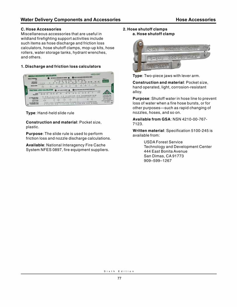
S i x t h E d i t i o n
77
Water Delivery Components and Accessories
C. Hose AccessoriesMiscellaneous accessories that are useful in wildland firefighting support activities include such items as hose discharge and friction loss calculators, hose shutoff clamps, mop-up kits, hose rollers, water storage tanks, hydrant wrenches, and others.
1. Discharge and friction loss calculators
Type: Hand-held slide rule
Construction and material: Pocket size, plastic.
Purpose: The slide rule is used to perform friction loss and nozzle discharge calculations.
Available: National Interagency Fire Cache System NFES 0897, fire equipment suppliers.
2. Hose shutoff clampsa. Hose shutoff clamp
Type: Two-piece jaws with lever arm.
Construction and material: Pocket size, hand operated, light, corrosion-resistant alloy.
Purpose: Shutoff water in hose line to prevent loss of water when a fire hose bursts, or for other purposes—such as rapid changing of nozzles, hoses, and so on.
Available from GSA: NSN 4210-00-767-7123.
Written material: Specification 5100-245 is available from:
USDA Forest Service Technology and Development Center 444 East Bonita Avenue San Dimas, CA 91773 909–599–1267
Hose Accessories
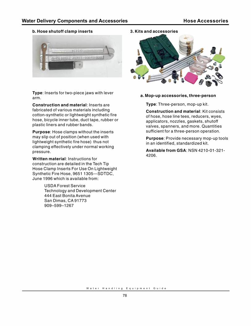
W a t e r H a n d l i n g E q u i p m e n t G u i d e
78
Water Delivery Components and Accessories
b. Hose shutoff clamp inserts
Type: Inserts for two-piece jaws with lever arm.
Construction and material: Inserts are fabricated of various materials including cotton-synthetic or lightweight synthetic fire hose, bicycle inner tube, duct tape, rubber or plastic liners and rubber bands.
Purpose: Hose clamps without the inserts may slip out of position (when used with lightweight synthetic fire hose) thus not clamping effectively under normal working pressure.
Written material: Instructions for construction are detailed in the Tech Tip Hose Clamp Inserts For Use On Lightweight Synthetic Fire Hose, 9651 1305—SDTDC, June 1996 which is available from:
USDA Forest Service Technology and Development Center 444 East Bonita Avenue San Dimas, CA 91773 909–599–1267
3. Kits and accessories
a. mop-up accessories, three-person
Type: Three-person, mop-up kit.
Construction and material: Kit consists of hose, hose line tees, reducers, wyes, applicators, nozzles, gaskets, shutoff valves, spanners, and more. Quantities sufficient for a three-person operation.
Purpose: Provide necessary mop-up tools in an identified, standardized kit.
Available from GSA: NSN 4210-01-321-4206.
Hose Accessories
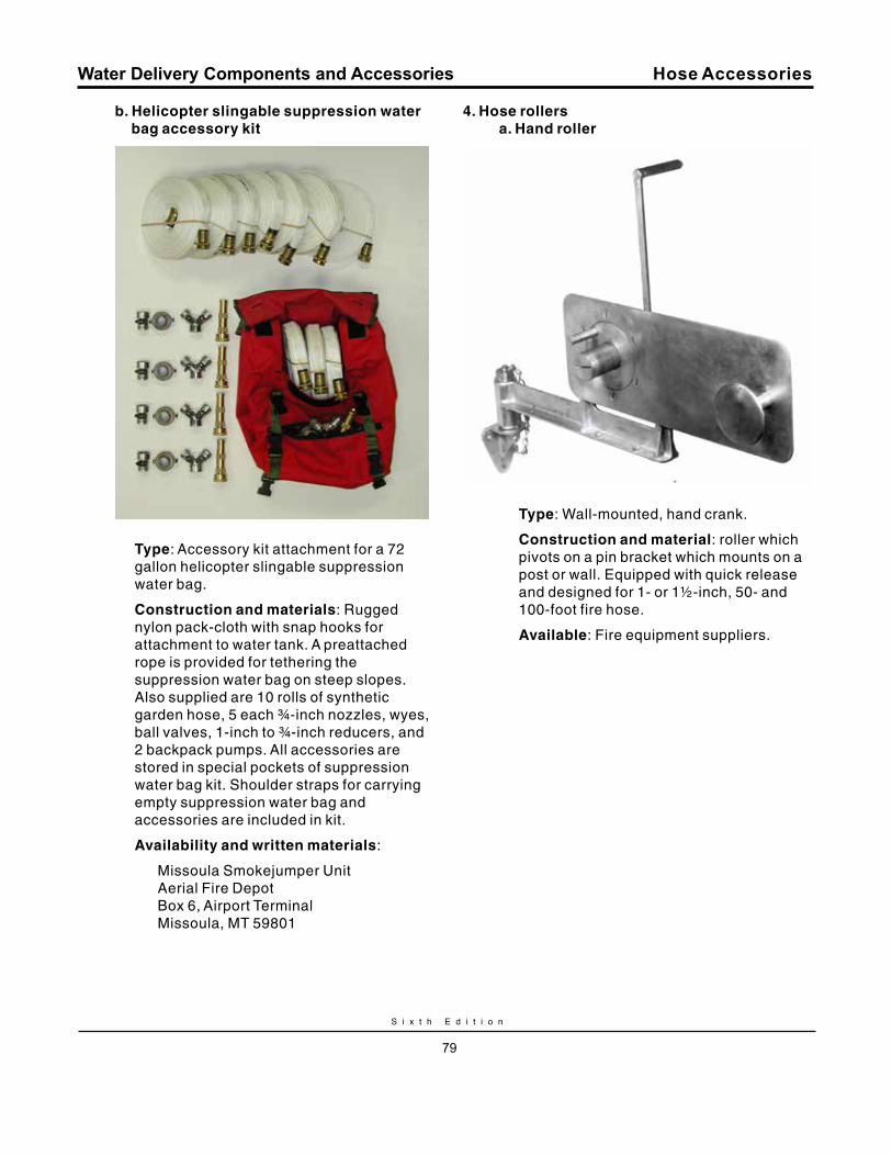
S i x t h E d i t i o n
79
Water Delivery Components and Accessories
b. Helicopter slingable suppression water bag accessory kit
Type: Accessory kit attachment for a 72 gallon helicopter slingable suppression water bag.
Construction and materials: Rugged nylon pack-cloth with snap hooks for attachment to water tank. A preattached rope is provided for tethering the suppression water bag on steep slopes. Also supplied are 10 rolls of synthetic garden hose, 5 each ¾-inch nozzles, wyes, ball valves, 1-inch to ¾-inch reducers, and 2 backpack pumps. All accessories are stored in special pockets of suppression water bag kit. Shoulder straps for carrying empty suppression water bag and accessories are included in kit.
Availability and written materials:
Missoula Smokejumper Unit Aerial Fire Depot Box 6, Airport Terminal Missoula, MT 59801
4. Hose rollersa. Hand roller
Type: Wall-mounted, hand crank.
Construction and material: roller which pivots on a pin bracket which mounts on a post or wall. Equipped with quick release and designed for 1- or 1½-inch, 50- and 100-foot fire hose.
Available: Fire equipment suppliers.
Hose Accessories
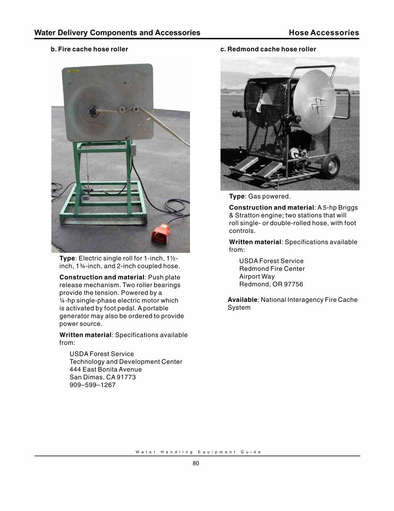
W a t e r H a n d l i n g E q u i p m e n t G u i d e
80
Water Delivery Components and Accessories
b. Fire cache hose roller
Type: Electric single roll for 1-inch, 1½-inch, 1¾-inch, and 2-inch coupled hose.
Construction and material: Push plate release mechanism. Two roller bearings provide the tension. Powered by a ¼-hp single-phase electric motor which is activated by foot pedal. A portable generator may also be ordered to provide power source.
Written material: Specifications available from:
USDA Forest Service Technology and Development Center 444 East Bonita Avenue San Dimas, CA 91773 909–599–1267
c. redmond cache hose roller
Type: Gas powered.
Construction and material: A 5-hp Briggs & Stratton engine; two stations that will roll single- or double-rolled hose, with foot controls.
Written material: Specifications available from:
USDA Forest Service Redmond Fire Center Airport Way Redmond, OR 97756
Available: National Interagency Fire Cache System
Hose Accessories
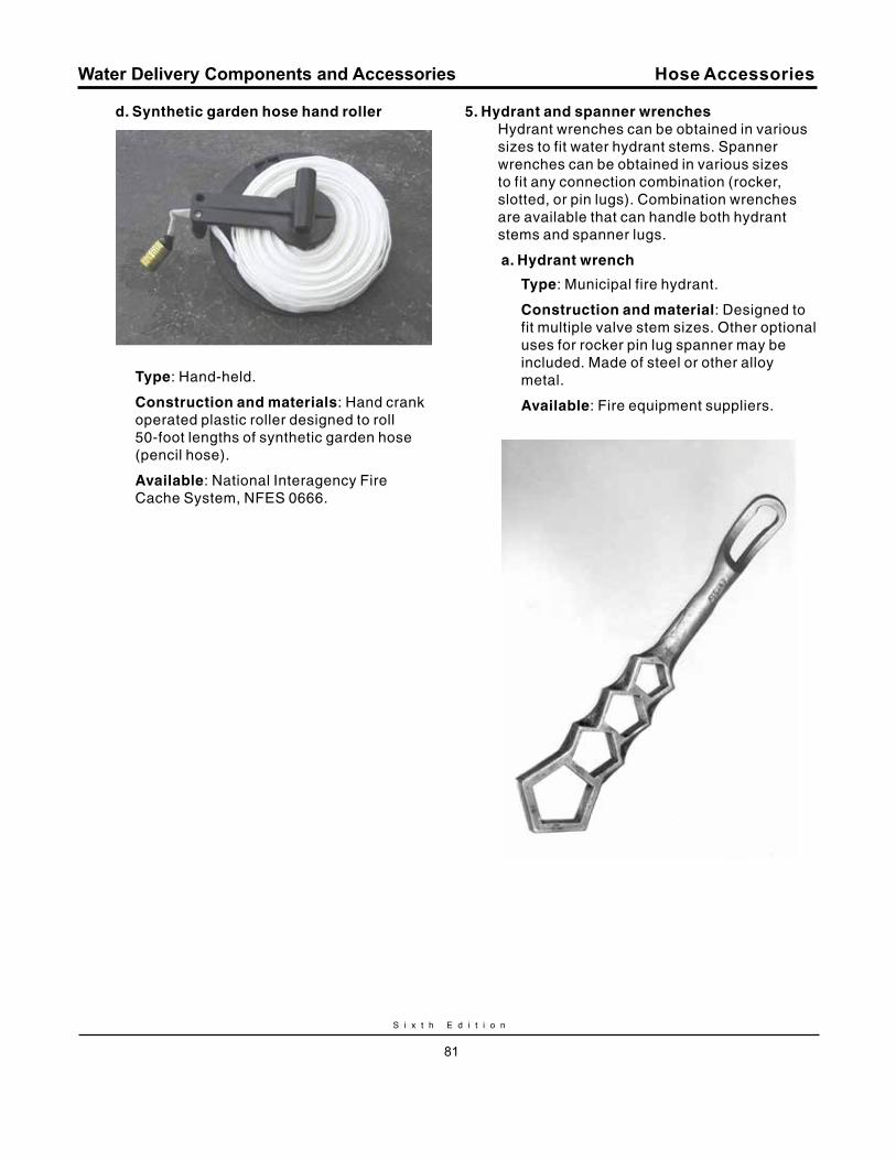
S i x t h E d i t i o n
81
Water Delivery Components and Accessories
d. Synthetic garden hose hand roller
Type: Hand-held.
Construction and materials: Hand crank operated plastic roller designed to roll 50-foot lengths of synthetic garden hose (pencil hose).
Available: National Interagency Fire Cache System, NFES 0666.
5. Hydrant and spanner wrenchesHydrant wrenches can be obtained in various sizes to fit water hydrant stems. Spanner wrenches can be obtained in various sizes to fit any connection combination (rocker, slotted, or pin lugs). Combination wrenches are available that can handle both hydrant stems and spanner lugs.
a. Hydrant wrench
Type: Municipal fire hydrant.
Construction and material: Designed to fit multiple valve stem sizes. Other optional uses for rocker pin lug spanner may be included. Made of steel or other alloy metal.
Available: Fire equipment suppliers.
Hose Accessories
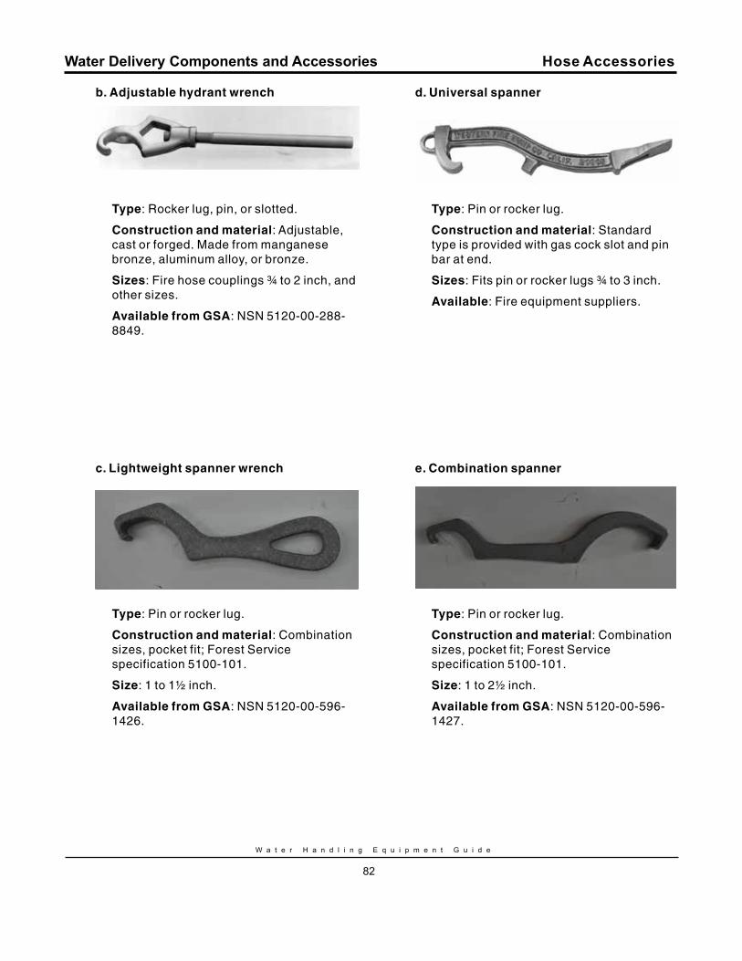
W a t e r H a n d l i n g E q u i p m e n t G u i d e
82
Water Delivery Components and Accessories
b. Adjustable hydrant wrench
Type: Rocker lug, pin, or slotted.
Construction and material: Adjustable, cast or forged. Made from manganese bronze, aluminum alloy, or bronze.
Sizes: Fire hose couplings ¾ to 2 inch, and other sizes.
Available from GSA: NSN 5120-00-288-8849.
c. Lightweight spanner wrench
Type: Pin or rocker lug.
Construction and material: Combination sizes, pocket fit; Forest Service specification 5100-101.
Size: 1 to 1½ inch.
Available from GSA: NSN 5120-00-596-1426.
d. universal spanner
Type: Pin or rocker lug.
Construction and material: Standard type is provided with gas cock slot and pin bar at end.
Sizes: Fits pin or rocker lugs ¾ to 3 inch.
Available: Fire equipment suppliers.
e. Combination spanner
Type: Pin or rocker lug.
Construction and material: Combination sizes, pocket fit; Forest Service specification 5100-101.
Size: 1 to 2½ inch.
Available from GSA: NSN 5120-00-596-1427.
Hose Accessories
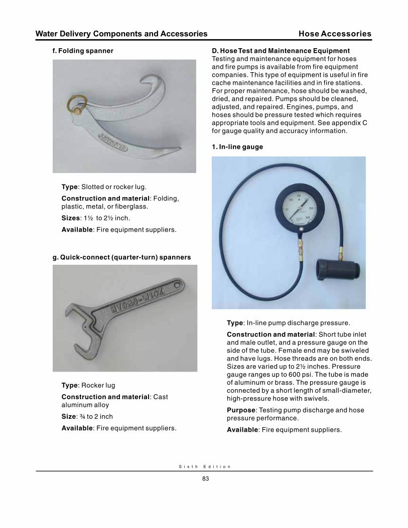
S i x t h E d i t i o n
83
Water Delivery Components and Accessories
f. Folding spanner
Type: Slotted or rocker lug.
Construction and material: Folding, plastic, metal, or fiberglass.
Sizes: 1½ to 2½ inch.
Available: Fire equipment suppliers.
g. quick-connect (quarter-turn) spanners
Type: Rocker lug
Construction and material: Cast aluminum alloy
Size: ¾ to 2 inch
Available: Fire equipment suppliers.
Hose Accessories
D. Hose Test and maintenance EquipmentTesting and maintenance equipment for hoses and fire pumps is available from fire equipment companies. This type of equipment is useful in fire cache maintenance facilities and in fire stations. For proper maintenance, hose should be washed, dried, and repaired. Pumps should be cleaned, adjusted, and repaired. Engines, pumps, and hoses should be pressure tested which requires appropriate tools and equipment. See appendix C for gauge quality and accuracy information.
1. In-line gauge
Type: In-line pump discharge pressure.
Construction and material: Short tube inlet and male outlet, and a pressure gauge on the side of the tube. Female end may be swiveled and have lugs. Hose threads are on both ends. Sizes are varied up to 2½ inches. Pressure gauge ranges up to 600 psi. The tube is made of aluminum or brass. The pressure gauge is connected by a short length of small-diameter, high-pressure hose with swivels.
Purpose: Testing pump discharge and hose pressure performance.
Available: Fire equipment suppliers.
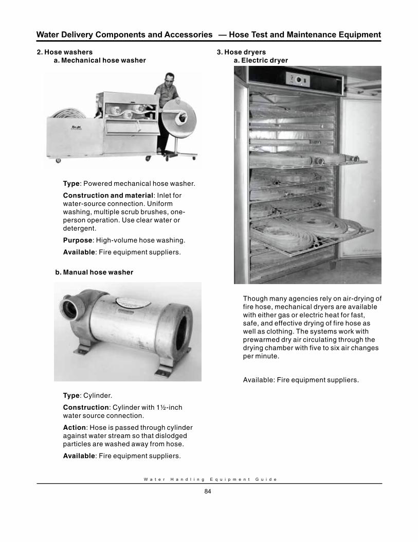
W a t e r H a n d l i n g E q u i p m e n t G u i d e
84
Water Delivery Components and Accessories
2. Hose washersa. mechanical hose washer
Type: Powered mechanical hose washer.
Construction and material: Inlet for water-source connection. Uniform washing, multiple scrub brushes, one-person operation. Use clear water or detergent.
Purpose: High-volume hose washing.
Available: Fire equipment suppliers.
b. manual hose washer
Type: Cylinder.
Construction: Cylinder with 1½-inch water source connection.
Action: Hose is passed through cylinder against water stream so that dislodged particles are washed away from hose.
Available: Fire equipment suppliers.
3. Hose dryersa. Electric dryer
Though many agencies rely on air-drying of fire hose, mechanical dryers are available with either gas or electric heat for fast, safe, and effective drying of fire hose as well as clothing. The systems work with prewarmed dry air circulating through the drying chamber with five to six air changes per minute.
Available: Fire equipment suppliers.
— Hose Test and Maintenance Equipment
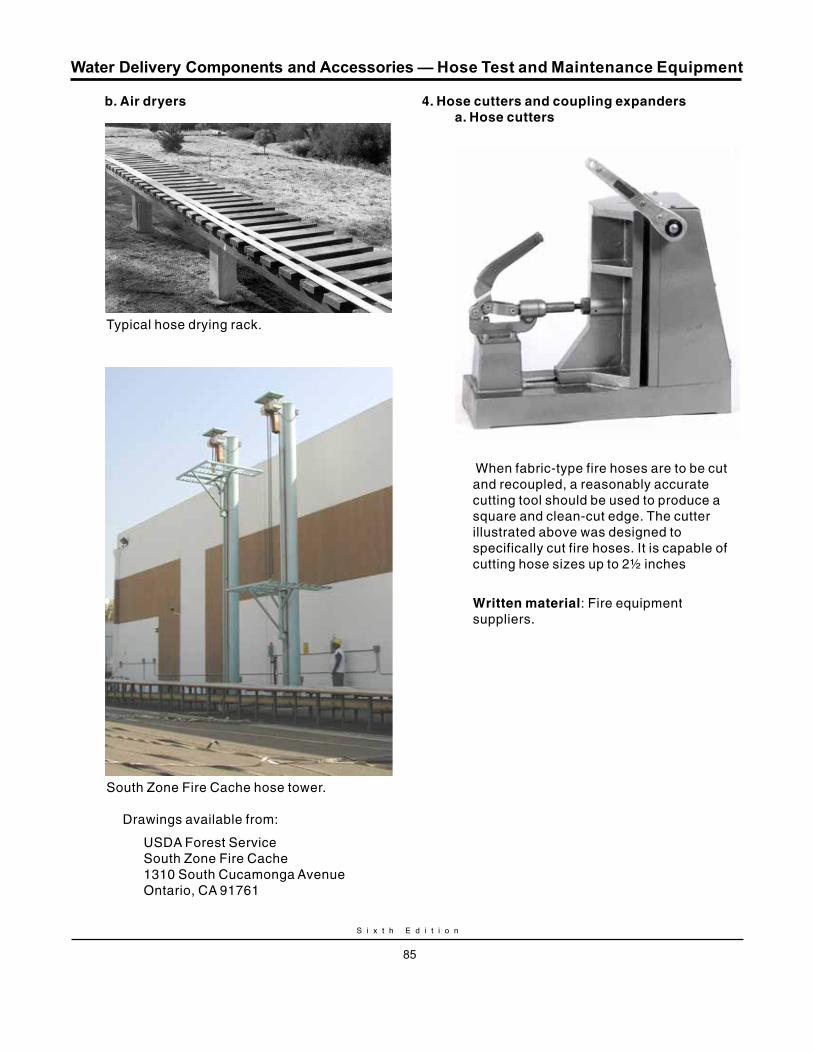
S i x t h E d i t i o n
85
Water Delivery Components and Accessories
b. Air dryers
Typical hose drying rack.
South Zone Fire Cache hose tower.
Drawings available from:
USDA Forest Service South Zone Fire Cache 1310 South Cucamonga Avenue Ontario, CA 91761
4. Hose cutters and coupling expandersa. Hose cutters
When fabric-type fire hoses are to be cut and recoupled, a reasonably accurate cutting tool should be used to produce a square and clean-cut edge. The cutter illustrated above was designed to specifically cut fire hoses. It is capable of cutting hose sizes up to 2½ inches
Written material: Fire equipment suppliers.
— Hose Test and Maintenance Equipment
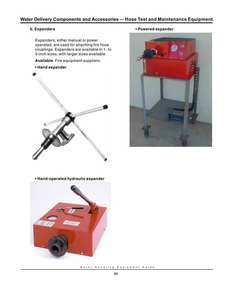
W a t e r H a n d l i n g E q u i p m e n t G u i d e
86
Water Delivery Components and Accessories
b. Expanders
Expanders, either manual or power operated, are used for attaching fire hose couplings. Expanders are available in 1- to 3-inch sizes, with larger sizes available.
Available: Fire equipment suppliers.
• Hand expander
• Hand-operated hydraulic expander
• Powered expander
— Hose Test and Maintenance Equipment

S i x t h E d i t i o n
87
Water Delivery Components and Accessories
5. Hose testers
Fire hose is subject to deterioration after use on fires and prolonged storage (subject to the elements of nature). A high-pressure test pump is essential for acceptance and service testing of all fire hose to assure compliance with specification, determine serviceability, permit discarding or repair of defective material, and for testing the adequacy of recoupling. Standard equipment usually includes a pump, suction connection, hose connection(s), pressure gauge, bypass and pressure-regulating valves, and may be hand operated or engine driven. Specific features and additional details are given in suppliers’ catalogs. The use of fire pumps for hose testing is not recommended.
— Hose Test and Maintenance Equipment
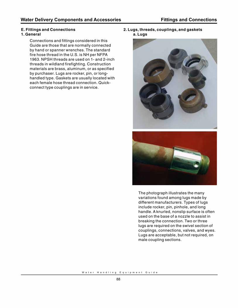
W a t e r H a n d l i n g E q u i p m e n t G u i d e
88
Water Delivery Components and Accessories
E. Fittings and Connections1. General
Connections and fittings considered in this Guide are those that are normally connected by hand or spanner wrenches. The standard fire hose thread in the U.S. is NH per NFPA 1963. NPSH threads are used on 1- and 2-inch threads in wildland firefighting. Construction materials are brass, aluminum, or as specified by purchaser. Lugs are rocker, pin, or long-handled type. Gaskets are usually located with each female hose thread connection. Quick-connect type couplings are in service.
2. Lugs, threads, couplings, and gasketsa. Lugs
The photograph illustrates the many variations found among lugs made by different manufacturers. Types of lugs include rocker, pin, pinhole, and long handle. A knurled, nonslip surface is often used on the base of a nozzle to assist in breaking the connection. Two or three lugs are required on the swivel section of couplings, connections, valves, and wyes. Lugs are acceptable, but not required, on male coupling sections.
Fittings and Connections
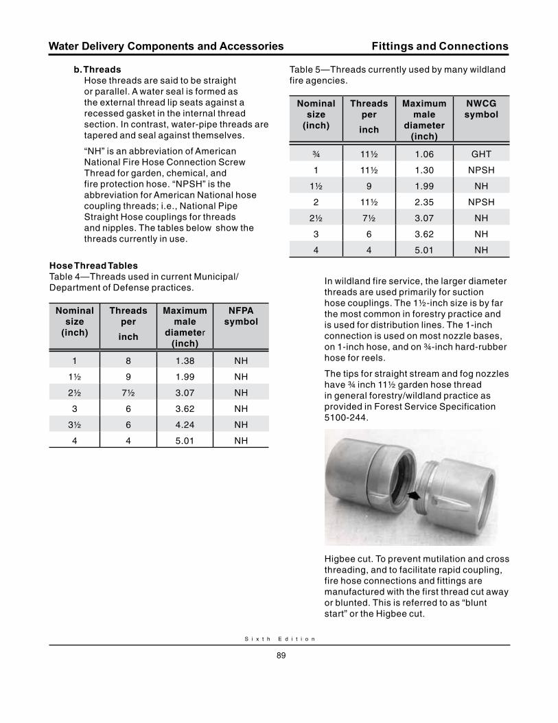
S i x t h E d i t i o n
89
Water Delivery Components and Accessories
b. ThreadsHose threads are said to be straight or parallel. A water seal is formed as the external thread lip seats against a recessed gasket in the internal thread section. In contrast, water-pipe threads are tapered and seal against themselves.
“NH” is an abbreviation of American National Fire Hose Connection Screw Thread for garden, chemical, and fire protection hose. “NPSH” is the abbreviation for American National hose coupling threads; i.e., National Pipe Straight Hose couplings for threads and nipples. The tables below show the threads currently in use.
Hose Thread TablesTable 4—Threads used in current Municipal/Department of Defense practices.
Nominal size
(inch)
Threads per
inch
maximum male
diameter (inch)
NFPA symbol
1 8 1.38 NH
1½ 9 1.99 NH
2½ 7½ 3.07 NH
3 6 3.62 NH
3½ 6 4.24 NH
4 4 5.01 NH
Table 5—Threads currently used by many wildland fire agencies.
Nominal size
(inch)
Threads per
inch
maximum male
diameter (inch)
NWCG symbol
¾ 11½ 1.06 GHT
1 11½ 1.30 NPSH
1½ 9 1.99 NH
2 11½ 2.35 NPSH
2½ 7½ 3.07 NH
3 6 3.62 NH
4 4 5.01 NH
In wildland fire service, the larger diameter threads are used primarily for suction hose couplings. The 1½-inch size is by far the most common in forestry practice and is used for distribution lines. The 1-inch connection is used on most nozzle bases, on 1-inch hose, and on ¾-inch hard-rubber hose for reels.
The tips for straight stream and fog nozzles have ¾ inch 11½ garden hose thread in general forestry/wildland practice as provided in Forest Service Specification 5100-244.
Higbee cut. To prevent mutilation and cross threading, and to facilitate rapid coupling, fire hose connections and fittings are manufactured with the first thread cut away or blunted. This is referred to as “blunt start” or the Higbee cut.
Fittings and Connections
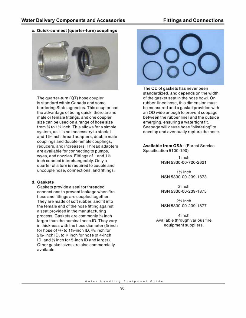
W a t e r H a n d l i n g E q u i p m e n t G u i d e
90
Water Delivery Components and Accessories
c. quick-connect (quarter-turn) couplings
The quarter-turn (QT) hose coupler is standard within Canada and some bordering State agencies. This coupler has the advantage of being quick, there are no male or female fittings, and one coupler size can be used on a range of hose size from ¾ to 1½ inch. This allows for a simple system, as it is not necessary to stock 1- and 1½-inch thread adapters, double male couplings and double female couplings, reducers, and increasers. Thread adapters are available for connecting to pumps, wyes, and nozzles. Fittings of 1 and 1½ inch connect interchangeably. Only a quarter of a turn is required to couple and uncouple hose, connections, and fittings.
d. GasketsGaskets provide a seal for threaded connections to prevent leakage when fire hose and fittings are coupled together. They are made of soft rubber, and fit into the female end of the hose fitting against a seat provided in the manufacturing process. Gaskets are commonly z inch larger than the nominal hose ID. They vary in thickness with the hose diameter (8 inch for hose of ¾- to 1½-inch ID, x inch for 2½- inch ID, to ¼ inch for hose of 4-inch ID, and a inch for 5-inch ID and larger). Other gasket sizes are also commercially available.
The OD of gaskets has never been standardized, and depends on the width of the gasket seat in the hose bowl. On rubber-lined hose, this dimension must be measured and a gasket provided with an OD wide enough to prevent seepage between the rubber liner and the outside emerging, ensuring a watertight fit. Seepage will cause hose “blistering” to develop and eventually rupture the hose.
Available from GSA : (Forest Service Specification 5100-190)
1 inch NSN 5330-00-720-2621
1½ inch NSN 5330-00-239-1873
2 inch NSN 5330-00-239-1875
2½ inch NSN 5330-00-239-1877
4 inchAvailable through various fire
equipment suppliers.
Fittings and Connections
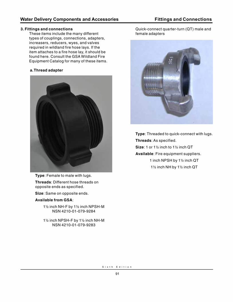
S i x t h E d i t i o n
91
Water Delivery Components and Accessories
3. Fittings and connectionsThese items include the many different types of couplings, connections, adapters, increasers, reducers, wyes, and valves required in wildland fire hose lays. If the item attaches to a fire hose lay, it should be found here. Consult the GSA Wildland Fire Equipment Catalog for many of these items.
a. Thread adapter
Type: Female to male with lugs.
Threads: Different hose threads on opposite ends as specified.
Size: Same on opposite ends.
Available from GSA:
1½ inch NH-F by 1½ inch NPSH-MNSN 4210-01-079-9284
1½ inch NPSH-F by 1½ inch NH-M NSN 4210-01-079-9283
Quick-connect quarter-turn (QT) male and female adapters
Type: Threaded to quick-connect with lugs.
Threads: As specified.
Size: 1 or 1½ inch to 1½ inch QT
Available: Fire equipment suppliers.
1 inch NPSH by 1½ inch QT
1½ inch NH by 1½ inch QT
Fittings and Connections
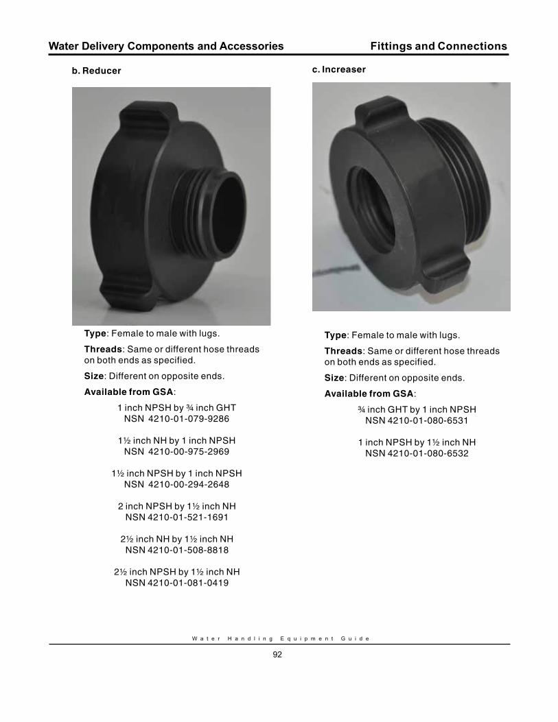
W a t e r H a n d l i n g E q u i p m e n t G u i d e
92
Water Delivery Components and Accessories
b. reducer
Type: Female to male with lugs.
Threads: Same or different hose threads on both ends as specified.
Size: Different on opposite ends.
Available from GSA:
1 inch NPSH by ¾ inch GHTNSN 4210-01-079-9286
1½ inch NH by 1 inch NPSHNSN 4210-00-975-2969
1½ inch NPSH by 1 inch NPSHNSN 4210-00-294-2648
2 inch NPSH by 1½ inch NHNSN 4210-01-521-1691
2½ inch NH by 1½ inch NHNSN 4210-01-508-8818
2½ inch NPSH by 1½ inch NHNSN 4210-01-081-0419
c. Increaser
Type: Female to male with lugs.
Threads: Same or different hose threads on both ends as specified.
Size: Different on opposite ends.
Available from GSA:
¾ inch GHT by 1 inch NPSHNSN 4210-01-080-6531
1 inch NPSH by 1½ inch NHNSN 4210-01-080-6532
Fittings and Connections
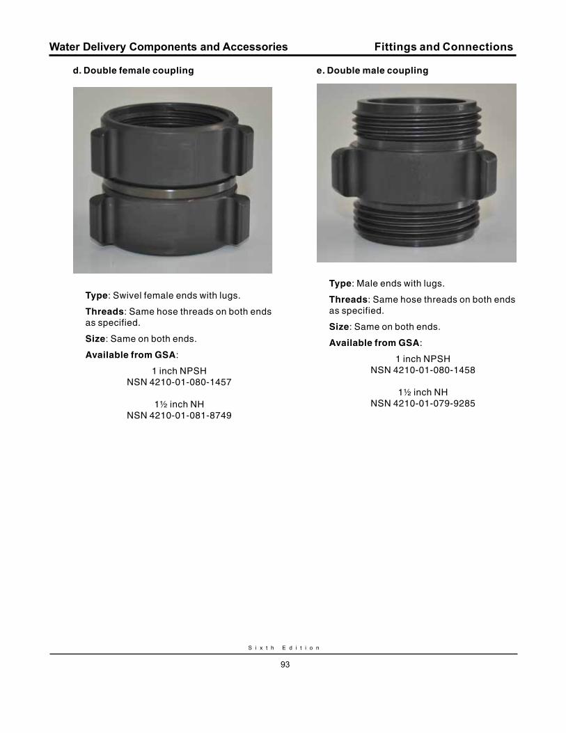
S i x t h E d i t i o n
93
Water Delivery Components and Accessories
d. Double female coupling
Type: Swivel female ends with lugs.
Threads: Same hose threads on both ends as specified.
Size: Same on both ends.
Available from GSA:
1 inch NPSHNSN 4210-01-080-1457
1½ inch NHNSN 4210-01-081-8749
e. Double male coupling
Type: Male ends with lugs.
Threads: Same hose threads on both ends as specified.
Size: Same on both ends.
Available from GSA:
1 inch NPSHNSN 4210-01-080-1458
1½ inch NH NSN 4210-01-079-9285
Fittings and Connections
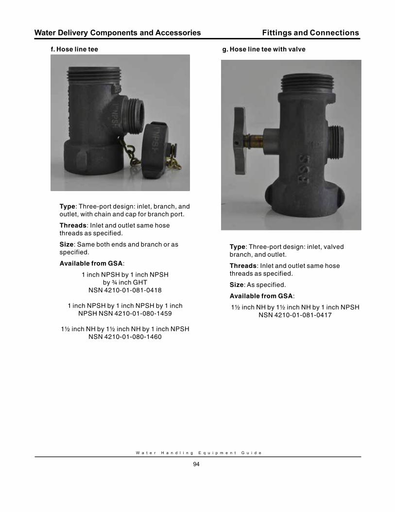
W a t e r H a n d l i n g E q u i p m e n t G u i d e
94
Water Delivery Components and Accessories
f. Hose line tee
Type: Three-port design: inlet, branch, and outlet, with chain and cap for branch port.
Threads: Inlet and outlet same hose threads as specified.
Size: Same both ends and branch or as specified.
Available from GSA:
1 inch NPSH by 1 inch NPSH by ¾ inch GHT
NSN 4210-01-081-0418
1 inch NPSH by 1 inch NPSH by 1 inch NPSH NSN 4210-01-080-1459
1½ inch NH by 1½ inch NH by 1 inch NPSHNSN 4210-01-080-1460
g. Hose line tee with valve
Type: Three-port design: inlet, valved branch, and outlet.
Threads: Inlet and outlet same hose threads as specified.
Size: As specified.
Available from GSA:
1½ inch NH by 1½ inch NH by 1 inch NPSH NSN 4210-01-081-0417
Fittings and Connections
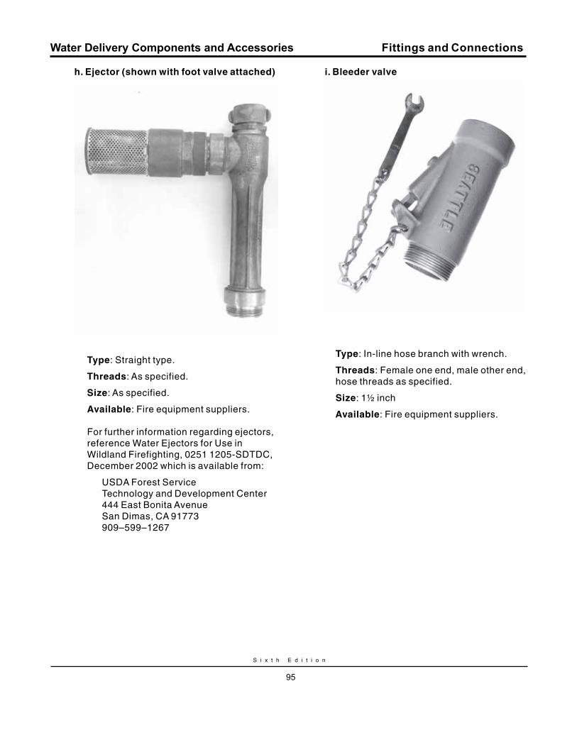
S i x t h E d i t i o n
95
Water Delivery Components and Accessories
h. Ejector (shown with foot valve attached)
Type: Straight type.
Threads: As specified.
Size: As specified.
Available: Fire equipment suppliers.
For further information regarding ejectors, reference Water Ejectors for Use in Wildland Firefighting, 0251 1205-SDTDC, December 2002 which is available from:
USDA Forest ServiceTechnology and Development Center444 East Bonita AvenueSan Dimas, CA 91773909–599–1267
i. Bleeder valve
Type: In-line hose branch with wrench.
Threads: Female one end, male other end, hose threads as specified.
Size: 1½ inch
Available: Fire equipment suppliers.
Fittings and Connections
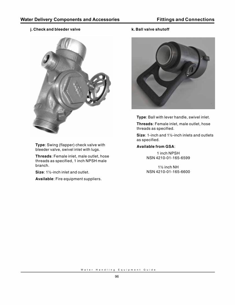
W a t e r H a n d l i n g E q u i p m e n t G u i d e
96
Water Delivery Components and Accessories
j. Check and bleeder valve
Type: Swing (flapper) check valve with bleeder valve, swivel inlet with lugs.
Threads: Female inlet, male outlet, hose threads as specified, 1 inch NPSH male branch.
Size: 1½-inch inlet and outlet.
Available: Fire equipment suppliers.
k. Ball valve shutoff
Type: Ball with lever handle, swivel inlet.
Threads: Female inlet, male outlet, hose threads as specified.
Size: 1-inch and 1½-inch inlets and outlets as specified.
Available from GSA:
1 inch NPSHNSN 4210-01-165-6599
1½ inch NHNSN 4210-01-165-6600
Fittings and Connections
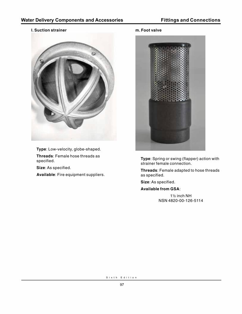
S i x t h E d i t i o n
97
Water Delivery Components and Accessories
l. Suction strainer
Type: Low-velocity, globe-shaped.
Threads: Female hose threads as specified.
Size: As specified.
Available: Fire equipment suppliers.
m. Foot valve
Type: Spring or swing (flapper) action with strainer female connection.
Threads: Female adapted to hose threads as specified.
Size: As specified.
Available from GSA:
1½ inch NHNSN 4820-00-126-5114
Fittings and Connections
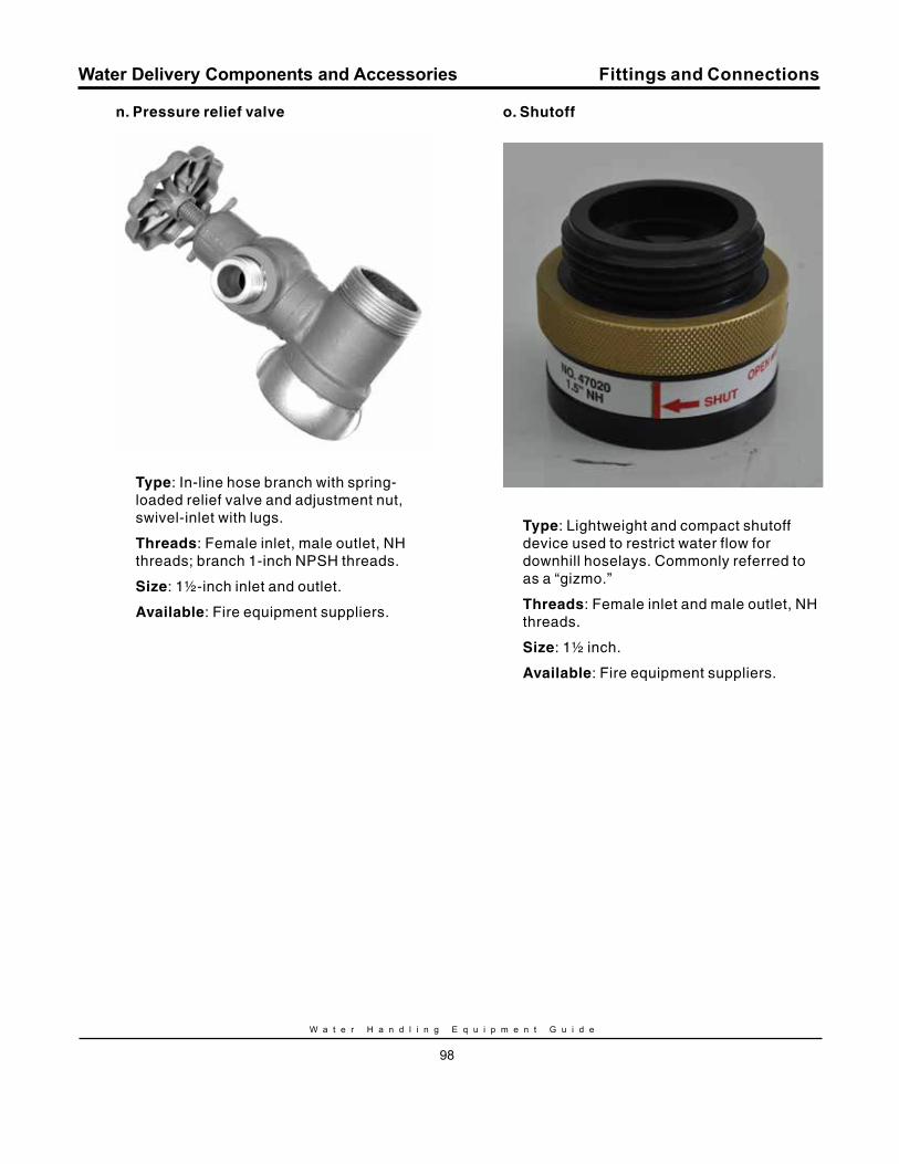
W a t e r H a n d l i n g E q u i p m e n t G u i d e
98
Water Delivery Components and Accessories
n. Pressure relief valve
Type: In-line hose branch with spring-loaded relief valve and adjustment nut, swivel-inlet with lugs.
Threads: Female inlet, male outlet, NH threads; branch 1-inch NPSH threads.
Size: 1½-inch inlet and outlet.
Available: Fire equipment suppliers.
o. Shutoff
Type: Lightweight and compact shutoff device used to restrict water flow for downhill hoselays. Commonly referred to as a “gizmo.”
Threads: Female inlet and male outlet, NH threads.
Size: 1½ inch.
Available: Fire equipment suppliers.
Fittings and Connections
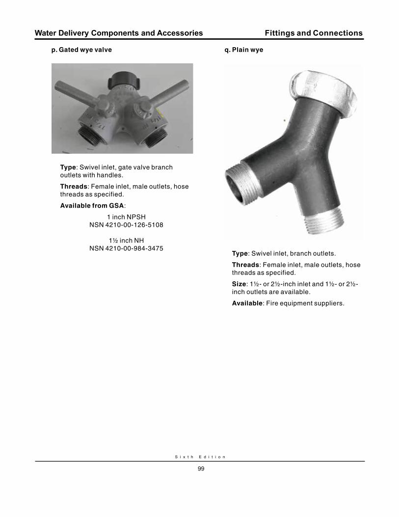
S i x t h E d i t i o n
99
Water Delivery Components and Accessories
p. Gated wye valve
Type: Swivel inlet, gate valve branch outlets with handles.
Threads: Female inlet, male outlets, hose threads as specified.
Available from GSA:
1 inch NPSHNSN 4210-00-126-5108
1½ inch NHNSN 4210-00-984-3475
q. Plain wye
Type: Swivel inlet, branch outlets.
Threads: Female inlet, male outlets, hose threads as specified.
Size: 1½- or 2½-inch inlet and 1½- or 2½- inch outlets are available.
Available: Fire equipment suppliers.
Fittings and Connections
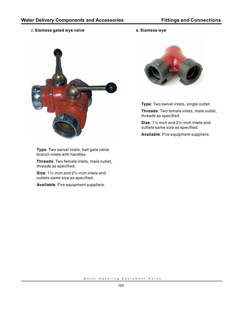
W a t e r H a n d l i n g E q u i p m e n t G u i d e
100
Water Delivery Components and Accessories
r. Siamese gated wye valve
Type: Two swivel inlets, ball gate valve branch inlets with handles.
Threads: Two female inlets, male outlet, threads as specified.
Size: 1½-inch and 2½-inch inlets and outlets same size as specified.
Available: Fire equipment suppliers.
s. Siamese wye
Type: Two swivel inlets, single outlet.
Threads: Two female inlets, male outlet, threads as specified.
Size: 1½-inch and 2½-inch inlets and outlets same size as specified.
Available: Fire equipment suppliers.
Fittings and Connections
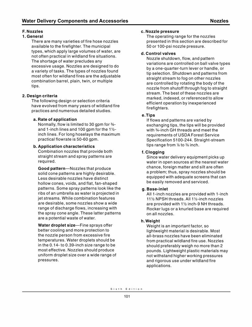
S i x t h E d i t i o n
101
Water Delivery Components and Accessories
F. Nozzles1. General
There are many varieties of fire hose nozzles available to the firefighter. The municipal types, which apply large volumes of water, are not often practical in wildland fire situations. The shortage of water precludes any excessive usage. Nozzles are designed to do a variety of tasks. The types of nozzles found most often for wildland fires are the adjustable combination barrel, plain, twin, or multiple tips.
2. Design criteriaThe following design or selection criteria have evolved from many years of wildland fire practices and numerous detailed studies.
a. rate of applicationNormally, flow is limited to 30 gpm for ¾- and 1-inch lines and 100 gpm for the 1½- inch lines. For long hoselays the maximum practical flowrate is 50-60 gpm.
b. Application characteristicsCombination nozzles that provide both straight stream and spray patterns are required.
Good pattern—Nozzles that produce solid cone patterns are highly desirable. Less desirable nozzles have distinct hollow cones, voids, and flat, fan-shaped patterns. Some spray patterns look like the ribs of an umbrella as water is projected in jet streams. While combination features are desirable, some nozzles show a wide range of discharge flows, increasing with the spray cone angle. These latter patterns are a potential waste of water.
Water droplet size—Fine sprays offer better cooling and more protection to the nozzle person from excessive fire temperatures. Water droplets should be in the 0.14- to 0.39-inch size range to be most effective. Nozzles should produce uniform droplet size over a wide range of pressures.
c. Nozzle pressureThe operating range for the nozzles presented in this section are described for 50 or 100-psi nozzle pressure.
d. Control valvesNozzle shutdown, flow, and pattern variations are controlled on ball valve types by a one-quarter-turn lever or handle, or tip selection. Shutdown and patterns from straight stream to fog on other nozzles are controlled by rotating the body of the nozzle from shutoff through fog to straight stream. The best of these nozzles are marked, indexed, or referenced to allow efficient operation by inexperienced firefighters.
e. TipsIf flows and patterns are varied by exchanging tips, the tips will be provided with ¾-inch GH threads and meet the requirements of USDA Forest Service Specification 5100-244. Straight-stream tips range from 8 to a inch.
f. CloggingSince water delivery equipment picks up water in open sources at the nearest water chance, foreign matter and silt are often a problem; thus, spray nozzles should be equipped with adequate screens that can be easily removed and serviced.
g. Base-inletAll 1-inch nozzles are provided with 1-inch 11½ NPSH threads. All 1½-inch nozzles are provided with 1½ inch-9 NH threads. Rocker lugs or a knurled base are required on all nozzles.
h. WeightWeight is an important factor, so lightweight material is desirable. Most all-brass nozzles have been eliminated from practical wildland fire use. Nozzles should preferably weigh no more than 2 pounds. Lightweight plastic materials may not withstand higher working pressures and rigorous use under wildland fire applications.
Nozzles
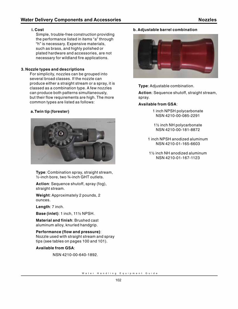
W a t e r H a n d l i n g E q u i p m e n t G u i d e
102
Water Delivery Components and Accessories
i. CostSimple, trouble-free construction providing the performance listed in items “a” through “h” is necessary. Expensive materials, such as brass, and highly polished or plated hardware and accessories, are not necessary for wildland fire applications.
3. Nozzle types and descriptionsFor simplicity, nozzles can be grouped into several broad classes. If the nozzle can produce either a straight stream or a spray, it is classed as a combination type. A few nozzles can produce both patterns simultaneously, but their flow requirements are high. The more common types are listed as follows:
a. Twin tip (forester)
Type: Combination spray, straight stream, ½-inch bore, two ¾-inch GHT outlets.
Action: Sequence shutoff, spray (fog), straight stream.
Weight: Approximately 2 pounds, 2 ounces.
Length: 7 inch.
Base (inlet): 1 inch, 11½ NPSH.
material and finish: Brushed cast aluminum alloy, knurled handgrip.
Performance (flow and pressure): Nozzle used with straight stream and spray tips (see tables on pages 100 and 101).
Available from GSA:
NSN 4210-00-640-1892.
b. Adjustable barrel combination
Type: Adjustable combination.
Action: Sequence shutoff, straight stream, spray.
Available from GSA:
1 inch NPSH polycarbonate NSN 4210-00-085-2291
1½ inch NH polycarbonate NSN 4210-00-181-8872
1 inch NPSH anodized aluminum NSN 4210-01-165-6603
1½ inch NH anodized aluminum
NSN 4210-01-167-1123
Nozzles
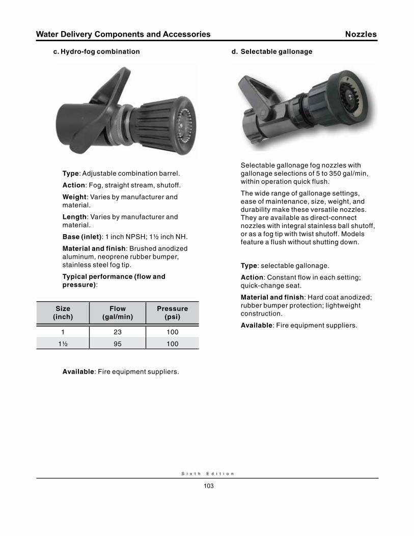
S i x t h E d i t i o n
103
Water Delivery Components and Accessories
c. Hydro-fog combination
Type: Adjustable combination barrel.
Action: Fog, straight stream, shutoff.
Weight: Varies by manufacturer and material.
Length: Varies by manufacturer and material.
Base (inlet): 1 inch NPSH; 1½ inch NH.
material and finish: Brushed anodized aluminum, neoprene rubber bumper, stainless steel fog tip.
Typical performance (flow and pressure):
Size (inch)
Flow (gal/min)
Pressure (psi)
1 23 100
1½ 95 100
Available: Fire equipment suppliers.
d. Selectable gallonage
Selectable gallonage fog nozzles with gallonage selections of 5 to 350 gal/min, within operation quick flush.
The wide range of gallonage settings, ease of maintenance, size, weight, and durability make these versatile nozzles. They are available as direct-connect nozzles with integral stainless ball shutoff, or as a fog tip with twist shutoff. Models feature a flush without shutting down.
Type: selectable gallonage.
Action: Constant flow in each setting; quick-change seat.
material and finish: Hard coat anodized; rubber bumper protection; lightweight construction.
Available: Fire equipment suppliers.
Nozzles

W a t e r H a n d l i n g E q u i p m e n t G u i d e
104
Water Delivery Components and Accessories
g. Fire hose mop-up nozzle (garden hose)
Garden hose nozzles are used for mop-up work. USDA Forest Service Specification 5100-243 covers material and construction of this nozzle.Type: Adjustable ¾-inch inlet.
Action: Adjustable spray, straight stream.
material and finish: Brass or aluminum.
Garden Hose Nozzle Performance ratings:
Position
min. discharge @ 100 psi (gal/min)
1—High-velocity, low- discharge, wide-angle spray
4
2—Straight-stream spray 5
3—Low-velocity, high-discharge spray
8
Available from GSA:
NSN 4730-00-595-1103
4. Nozzle tipsSince nozzle tips are comparatively small (in size), ¾-inch GHT has been adopted for the base thread. The USDA Forest Service maintains Specification 5100-244 on straight stream and spray tips. This specification lists five different diameter straight-stream tips and eight different flows (gal/min) in spray tips. The bore diameter is identified on the outlet flange of the straight-stream tips, and the flow (gal/min) is stamped on the body of the spray tips. The spray tips are designed to withstand a pressure of 600 psi. Straight-stream tips are designed to withstand a pressure of 200 psi. Materials and construction are detailed in Forest Service Specification 5100-244.
a. Straight stream
Straight-stream tips are designed and inspected to produce the following performance:
Tip size (inch)
min. stream @
100 psi (feet)*
min. Flow rate @ 100 psi
(gal/min)
max. Flow rate @ 100 psi
(gal/min)
8 29 4.2 5.2
x 34 9.4 11.6
¼ 40 16.8 20.6
c 41 25.3 32.1
a 41 37.9 46.3
*Measured 36 inches above the ground, and to the center of the area where the stream strikes the ground.
Available from GSA:
x inchNSN 4210-00-203-3855
¼ inchNSN 4210-00-177-6135
a inchNSN 4210-00-203-3845
Nozzles
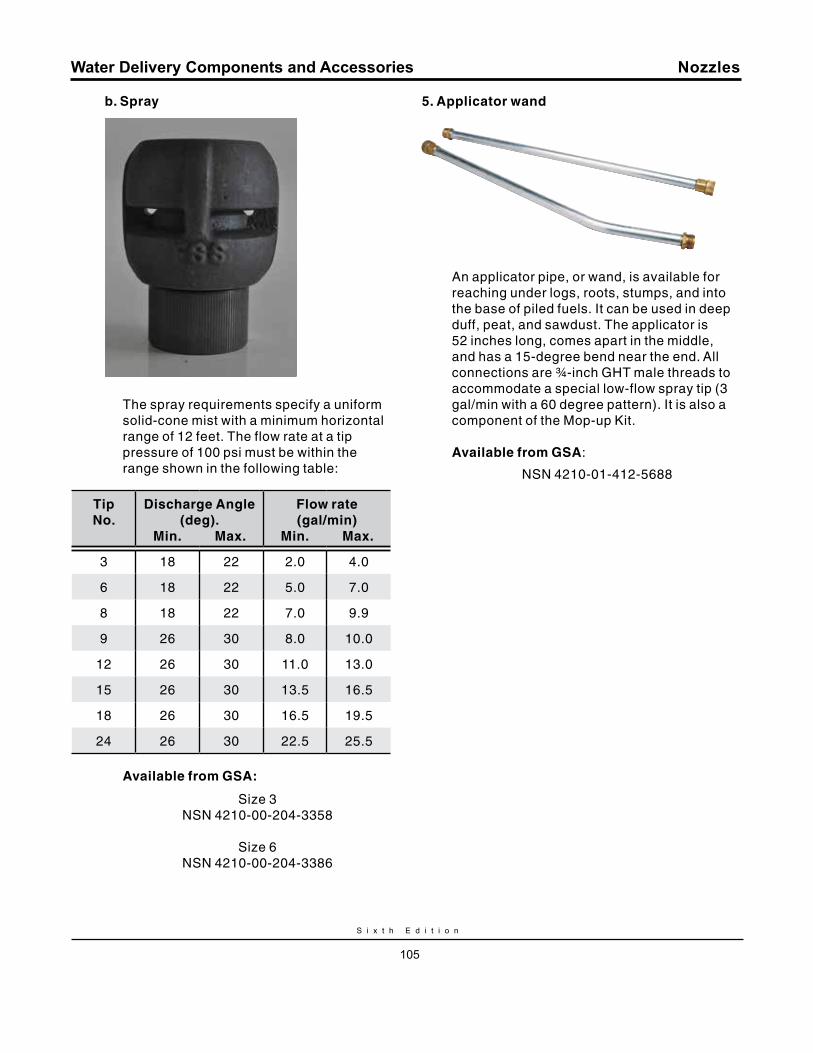
S i x t h E d i t i o n
105
Water Delivery Components and Accessories
b. Spray
The spray requirements specify a uniform solid-cone mist with a minimum horizontal range of 12 feet. The flow rate at a tip pressure of 100 psi must be within the range shown in the following table:
Tip No.
Discharge Angle (deg).
min. max.
Flow rate (gal/min)
min. max.
3 18 22 2.0 4.0
6 18 22 5.0 7.0
8 18 22 7.0 9.9
9 26 30 8.0 10.0
12 26 30 11.0 13.0
15 26 30 13.5 16.5
18 26 30 16.5 19.5
24 26 30 22.5 25.5
Available from GSA:
Size 3NSN 4210-00-204-3358
Size 6NSN 4210-00-204-3386
5. Applicator wand
An applicator pipe, or wand, is available for reaching under logs, roots, stumps, and into the base of piled fuels. It can be used in deep duff, peat, and sawdust. The applicator is 52 inches long, comes apart in the middle, and has a 15-degree bend near the end. All connections are ¾-inch GHT male threads to accommodate a special low-flow spray tip (3 gal/min with a 60 degree pattern). It is also a component of the Mop-up Kit.
Available from GSA:
NSN 4210-01-412-5688
Nozzles
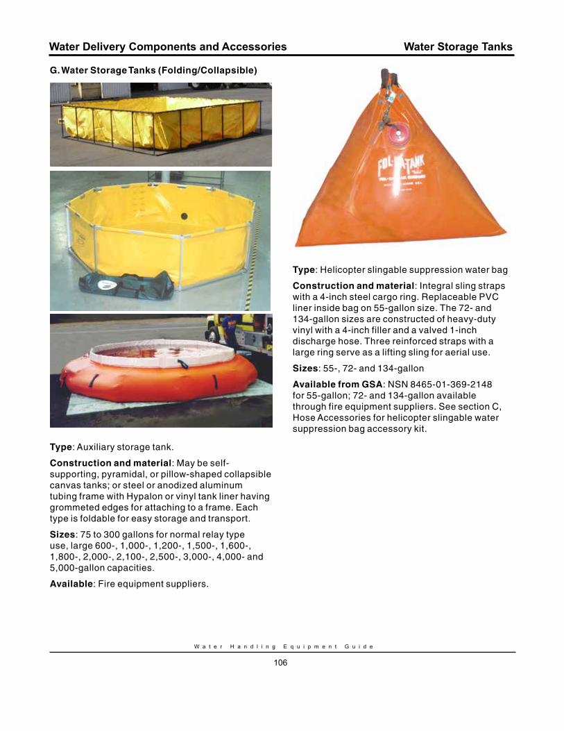
W a t e r H a n d l i n g E q u i p m e n t G u i d e
106
Water Delivery Components and Accessories
G. Water Storage Tanks (Folding/Collapsible)
Type: Auxiliary storage tank.
Construction and material: May be self-supporting, pyramidal, or pillow-shaped collapsible canvas tanks; or steel or anodized aluminum tubing frame with Hypalon or vinyl tank liner having grommeted edges for attaching to a frame. Each type is foldable for easy storage and transport.
Sizes: 75 to 300 gallons for normal relay type use, large 600-, 1,000-, 1,200-, 1,500-, 1,600-, 1,800-, 2,000-, 2,100-, 2,500-, 3,000-, 4,000- and 5,000-gallon capacities.
Available: Fire equipment suppliers.
Type: Helicopter slingable suppression water bag
Construction and material: Integral sling straps with a 4-inch steel cargo ring. Replaceable PVC liner inside bag on 55-gallon size. The 72- and 134-gallon sizes are constructed of heavy-duty vinyl with a 4-inch filler and a valved 1-inch discharge hose. Three reinforced straps with a large ring serve as a lifting sling for aerial use.
Sizes: 55-, 72- and 134-gallon
Available from GSA: NSN 8465-01-369-2148 for 55-gallon; 72- and 134-gallon available through fire equipment suppliers. See section C, Hose Accessories for helicopter slingable water suppression bag accessory kit.
Water Storage Tanks
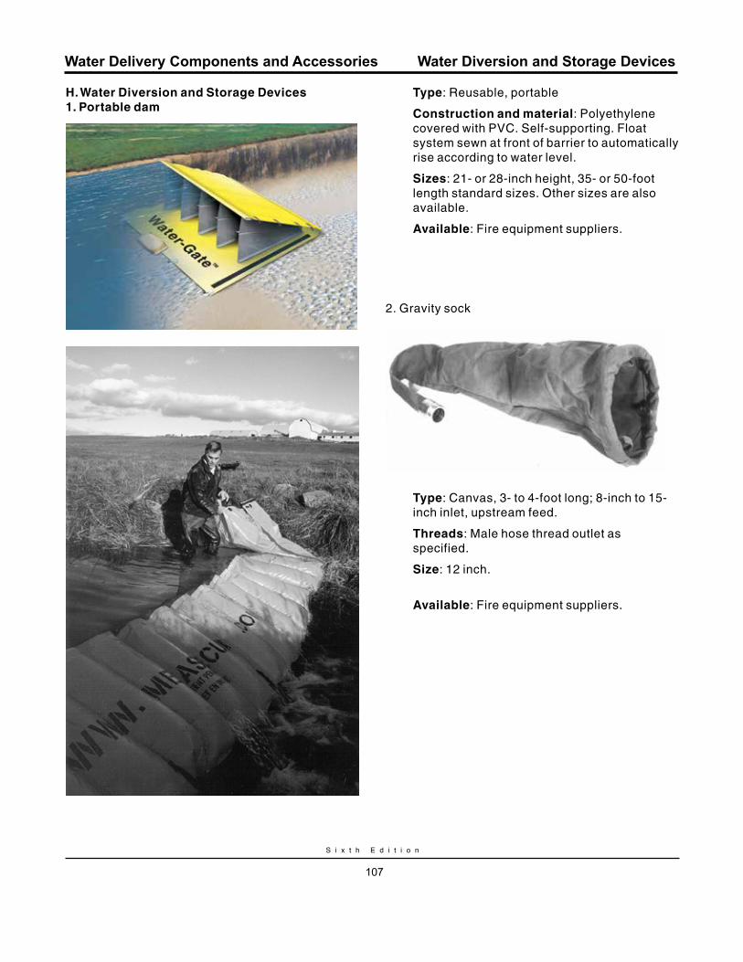
S i x t h E d i t i o n
107
Water Delivery Components and Accessories
H. Water Diversion and Storage Devices1. Portable dam
Type: Reusable, portable
Construction and material: Polyethylene covered with PVC. Self-supporting. Float system sewn at front of barrier to automatically rise according to water level.
Sizes: 21- or 28-inch height, 35- or 50-foot length standard sizes. Other sizes are also available.
Available: Fire equipment suppliers.
2. Gravity sock
Type: Canvas, 3- to 4-foot long; 8-inch to 15-inch inlet, upstream feed.
Threads: Male hose thread outlet as specified.
Size: 12 inch.
Available: Fire equipment suppliers.
Water Diversion and Storage Devices
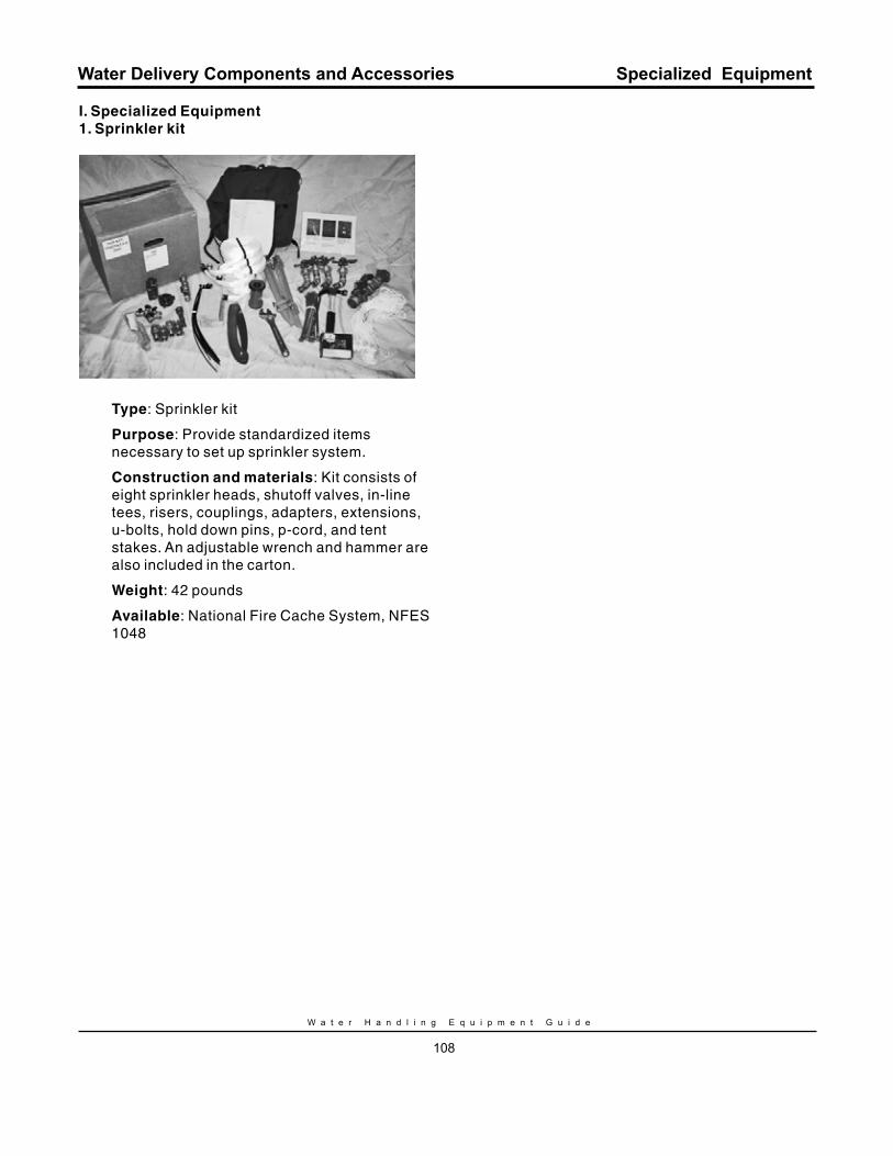
W a t e r H a n d l i n g E q u i p m e n t G u i d e
108
Water Delivery Components and Accessories
I. Specialized Equipment1. Sprinkler kit
Type: Sprinkler kit
Purpose: Provide standardized items necessary to set up sprinkler system.
Construction and materials: Kit consists of eight sprinkler heads, shutoff valves, in-line tees, risers, couplings, adapters, extensions, u-bolts, hold down pins, p-cord, and tent stakes. An adjustable wrench and hammer are also included in the carton.
Weight: 42 pounds
Available: National Fire Cache System, NFES 1048
Specialized Equipment

CH
AP
TE
R I
VA
PP
EN
DI
XE
S

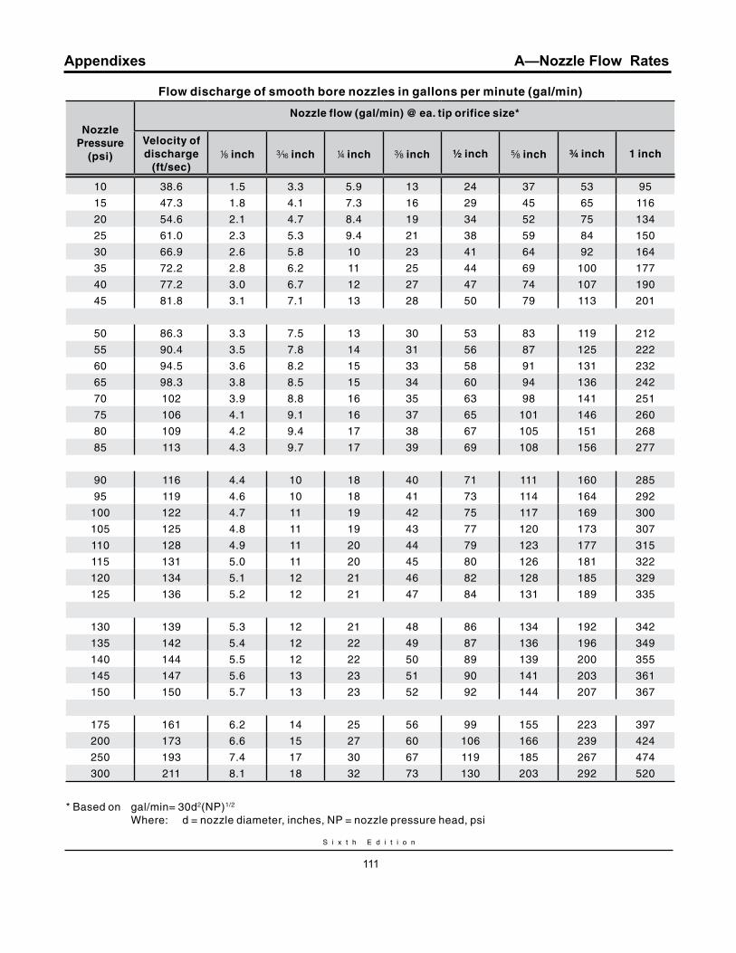
S i x t h E d i t i o n
111
Appendixes
Flow discharge of smooth bore nozzles in gallons per minute (gal/min)
Nozzle Pressure
(psi)
Nozzle flow (gal/min) @ ea. tip orifice size*
velocity of discharge
(ft/sec)8 inch x inch 4 inch a inch ½ inch s inch ¾ inch 1 inch
10 38.6 1.5 3.3 5.9 13 24 37 53 95
15 47.3 1.8 4.1 7.3 16 29 45 65 116
20 54.6 2.1 4.7 8.4 19 34 52 75 134
25 61.0 2.3 5.3 9.4 21 38 59 84 150
30 66.9 2.6 5.8 10 23 41 64 92 164
35 72.2 2.8 6.2 11 25 44 69 100 177
40 77.2 3.0 6.7 12 27 47 74 107 190
45 81.8 3.1 7.1 13 28 50 79 113 201
50 86.3 3.3 7.5 13 30 53 83 119 212
55 90.4 3.5 7.8 14 31 56 87 125 222
60 94.5 3.6 8.2 15 33 58 91 131 232
65 98.3 3.8 8.5 15 34 60 94 136 242
70 102 3.9 8.8 16 35 63 98 141 251
75 106 4.1 9.1 16 37 65 101 146 260
80 109 4.2 9.4 17 38 67 105 151 268
85 113 4.3 9.7 17 39 69 108 156 277
90 116 4.4 10 18 40 71 111 160 285
95 119 4.6 10 18 41 73 114 164 292
100 122 4.7 11 19 42 75 117 169 300
105 125 4.8 11 19 43 77 120 173 307
110 128 4.9 11 20 44 79 123 177 315
115 131 5.0 11 20 45 80 126 181 322
120 134 5.1 12 21 46 82 128 185 329
125 136 5.2 12 21 47 84 131 189 335
130 139 5.3 12 21 48 86 134 192 342
135 142 5.4 12 22 49 87 136 196 349
140 144 5.5 12 22 50 89 139 200 355
145 147 5.6 13 23 51 90 141 203 361
150 150 5.7 13 23 52 92 144 207 367
175 161 6.2 14 25 56 99 155 223 397
200 173 6.6 15 27 60 106 166 239 424
250 193 7.4 17 30 67 119 185 267 474
300 211 8.1 18 32 73 130 203 292 520
* Based on gal/min= 30d2(NP)1/2
Where: d = nozzle diameter, inches, NP = nozzle pressure head, psi
A—Nozzle Flow Rates

S i x t h E d i t i o n
113
Appendixes
BackgroundDuring fire suppression activities that require hose lays it is important to size up the situation and make some quick but beneficial hydraulic calculations. Some items to consider are pump capability needed, adequacy of water source, and the type of hose lay to use. Friction loss in fire hose may result in the inability of firefighters to complete their mission.
Friction loss is the result of turbulence within the water (fluids) and the resistance along the inside wall of fire hose. Friction loss is one of the factors that must be taken into consideration when determining pump capabilities. Friction loss depends on the volume of water moving through the hose, diameter and length of hose, and the internal roughness of the hose.
The National Technology and Development Center, San Dimas, CA published a Tech Tip titled Friction Loss in Wildland Hoselays (0651 1309—SDTDC).
Five Significant Hydraulic relationships…Governing Friction Loss
1. For the same flow, friction loss varies approximately inversely as the fifth power of the diameter of the hose.
This means if the flow remains the same, increasing the size of the hose can drastically reduce the friction loss; or, the bigger the hose (with the same flow) the smaller the friction loss. Double the diameter of the hose (with the same flow) and the friction loss will be reduced to 1/32,or about 3 percent.
2. In the same size hose, friction loss varies approximately as the square of the flow.
This means that the resultant friction loss increases more rapidly than the increase in flow. For example, if the flow is doubled, the friction loss becomes 4 times as much. If the flow is tripled, the friction loss becomes 9 times as much; if the flow is quadrupled, the friction loss becomes 16 times as much as it was originally.
3. Friction loss is directly proportional to length, provided all other conditions are equal.
If identical gallons per minute are flowing, the friction loss in 500 feet of hose will be five times the friction loss in 100 feet of the same size and quality hose. (If you double the length of the line you double the friction loss).
4. Friction loss is affected by the roughness of the inside of the hose in relation to the diameter.
The rougher the hose, the more the friction loss. The smaller the hose with the same roughness, the greater the friction loss.
5. Friction loss is nearly independent of pressure.
For a given flow, the friction loss is the same whether the pressure is 50 psi or 400 psi.
B—Pressure and Flow Rates

W a t e r H a n d l i n g E q u i p m e n t G u i d e
114
AppendixesC
om
pa
rati
ve
Dia
me
ters
an
d W
eig
hts
(10
0-f
t) L
en
gth
s(C
ou
ple
d)
Ho
se
Ty
pe
ID (i
n)
FS
Sp
ec
Ja
cke
t
Wo
rkin
g
(ra
ted
) P
ress
ure
(p
si)
Dry
W
eig
ht
(lb
)
Wa
ter
(ga
l)W
eig
ht
Wa
ter
(lb
)
Tota
l W
eig
ht
(lb
)
Ga
rde
n (
GH
)s
No
ne
Sin
gle
20
02
1.6
13
15
Hig
h p
ress
ure
ru
bb
er
ha
rdlin
e¾
18
5—
60
05
6 2
.31
97
5
Hig
h p
ress
ure
ru
bb
er
ha
rdlin
e (
Bo
ost
er)
1N
on
e—
80
06
3 4
.13
49
7
Co
tto
n-s
ynth
eti
c ru
bb
er-
line
d (
CS
RL
)1
18
6S
ing
le3
00
20
4.1
34
54
Lig
htw
eig
ht S
ynth
eti
c T
ype
11
18
7S
ing
le3
00
10
4.1
34
44
Lig
htw
eig
ht S
ynth
eti
c T
ype
21
18
7S
ing
le3
00
10
4.1
34
44
Wo
ven
fab
ric
ha
rdlin
e1
No
ne
Sin
gle
30
01
7 4
.13
45
1
Co
tto
n-s
ynth
eti
c ru
bb
er-
line
d (
CS
RL
)1
½1
86
Sin
gle
30
02
7 9
.27
71
04
Lig
htw
eig
ht S
ynth
eti
c T
ype
11
½1
87
Sin
gle
30
01
3 9
.27
79
0
Lig
htw
eig
ht S
ynth
eti
c T
ype
21
½1
87
Sin
gle
30
01
6 9
.27
79
3
Lin
ed
2½
No
ne
Do
ub
le4
00
23
25
.42
13
23
6
NA
= n
ot a
vaila
ble
Co
up
ling
se
ts (
12
inch
) va
ry in
we
igh
t fro
m 0
.9 to
1.6
po
un
ds.
B—Pressure and Flow Rates
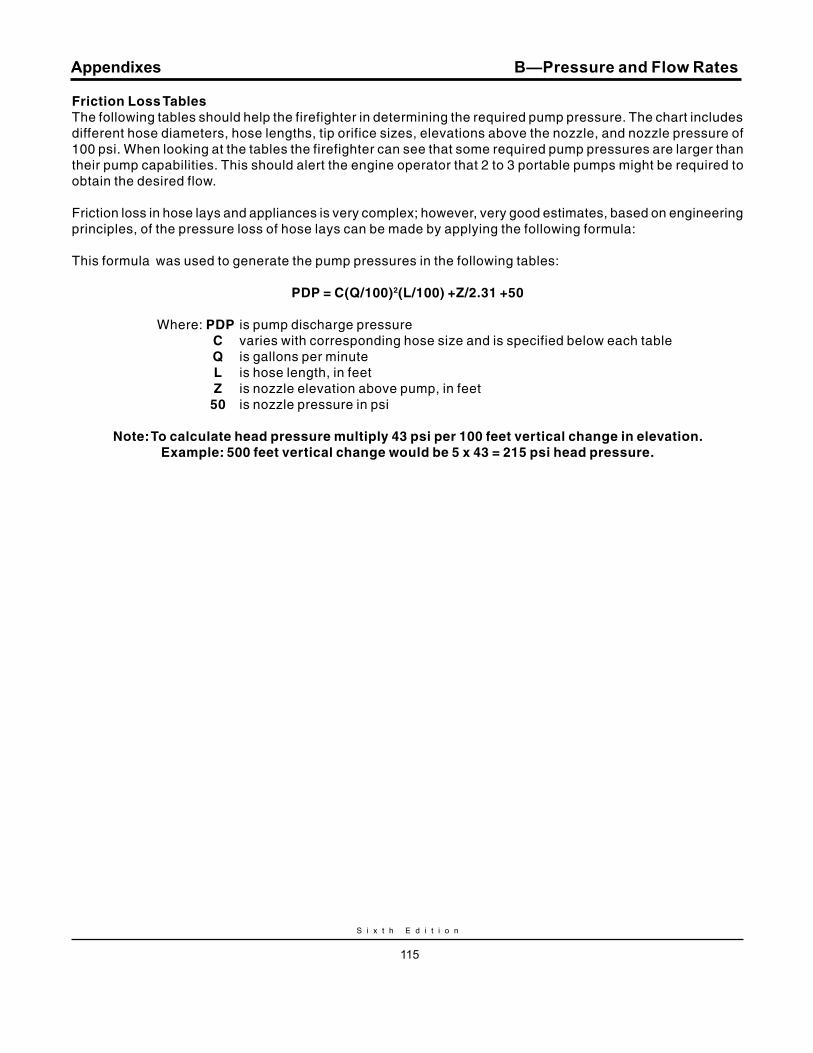
S i x t h E d i t i o n
115
Appendixes
Friction Loss TablesThe following tables should help the firefighter in determining the required pump pressure. The chart includes different hose diameters, hose lengths, tip orifice sizes, elevations above the nozzle, and nozzle pressure of 100 psi. When looking at the tables the firefighter can see that some required pump pressures are larger than their pump capabilities. This should alert the engine operator that 2 to 3 portable pumps might be required to obtain the desired flow.
Friction loss in hose lays and appliances is very complex; however, very good estimates, based on engineering principles, of the pressure loss of hose lays can be made by applying the following formula:
This formula was used to generate the pump pressures in the following tables:
PDP = C(q/100)2(L/100) +Z/2.31 +50
Where: PDP is pump discharge pressure C varies with corresponding hose size and is specified below each table q is gallons per minute L is hose length, in feet Z is nozzle elevation above pump, in feet 50 is nozzle pressure in psi
Note: To calculate head pressure multiply 43 psi per 100 feet vertical change in elevation. Example: 500 feet vertical change would be 5 x 43 = 215 psi head pressure.
B—Pressure and Flow Rates
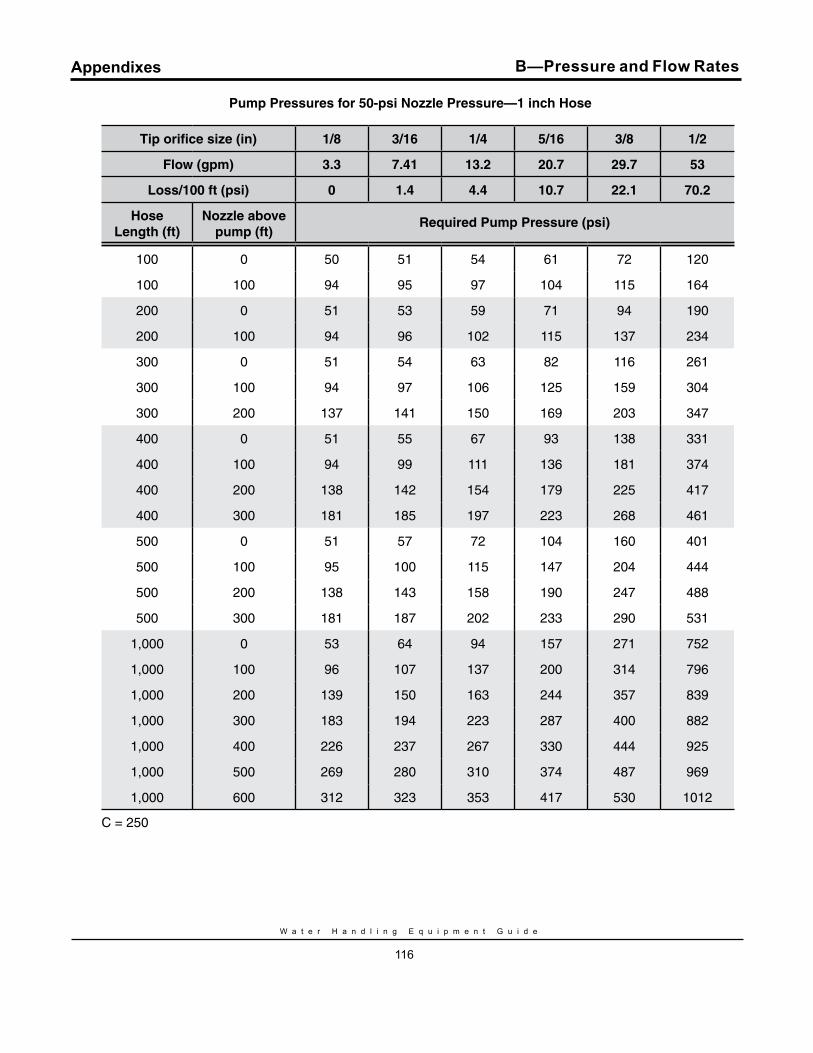
W a t e r H a n d l i n g E q u i p m e n t G u i d e
116
Appendixes
Pump Pressures for 50-psi Nozzle Pressure —1 inch Hose
Tip orifice size (in) 1/8 3/16 1/4 5/16 3/8 1/2
Flow (gpm) 3.3 7.41 13.2 20.7 29.7 53
Loss/100 ft (psi) 0 1.4 4.4 10.7 22.1 70.2
Hose Length (ft)
Nozzle above pump (ft)
required Pump Pressure (psi)
100 0 50 51 54 61 72 120
100 100 94 95 97 104 115 164
200 0 51 53 59 71 94 190
200 100 94 96 102 115 137 234
300 0 51 54 63 82 116 261
300 100 94 97 106 125 159 304
300 200 137 141 150 169 203 347
400 0 51 55 67 93 138 331
400 100 94 99 111 136 181 374
400 200 138 142 154 179 225 417
400 300 181 185 197 223 268 461
500 0 51 57 72 104 160 401
500 100 95 100 115 147 204 444
500 200 138 143 158 190 247 488
500 300 181 187 202 233 290 531
1,000 0 53 64 94 157 271 752
1,000 100 96 107 137 200 314 796
1,000 200 139 150 163 244 357 839
1,000 300 183 194 223 287 400 882
1,000 400 226 237 267 330 444 925
1,000 500 269 280 310 374 487 969
1,000 600 312 323 353 417 530 1012
C = 250
B—Pressure and Flow Rates
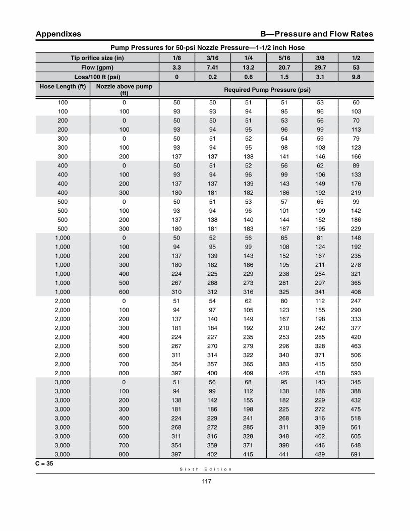
S i x t h E d i t i o n
117
AppendixesPump Pressures for 50-psi Nozzle Pressure—1-1/2 inch Hose
Tip orifice size (in) 1/8 3/16 1/4 5/16 3/8 1/2
Flow (gpm) 3.3 7.41 13.2 20.7 29.7 53
Loss/100 ft (psi) 0 0.2 0.6 1.5 3.1 9.8
Hose Length (ft) Nozzle above pump (ft)
required Pump Pressure (psi)
100 0 50 50 51 51 53 60
100 100 93 93 94 95 96 103
200 0 50 50 51 53 56 70
200 100 93 94 95 96 99 113
300 0 50 51 52 54 59 79
300 100 93 94 95 98 103 123
300 200 137 137 138 141 146 166
400 0 50 51 52 56 62 89
400 100 93 94 96 99 106 133
400 200 137 137 139 143 149 176
400 300 180 181 182 186 192 219
500 0 50 51 53 57 65 99
500 100 93 94 96 101 109 142
500 200 137 138 140 144 152 186
500 300 180 181 183 187 195 229
1,000 0 50 52 56 65 81 148
1,000 100 94 95 99 108 124 192
1,000 200 137 139 143 152 167 235
1,000 300 180 182 186 195 211 278
1,000 400 224 225 229 238 254 321
1,000 500 267 268 273 281 297 365
1,000 600 310 312 316 325 341 408
2,000 0 51 54 62 80 112 247
2,000 100 94 97 105 123 155 290
2,000 200 137 140 149 167 198 333
2,000 300 181 184 192 210 242 377
2,000 400 224 227 235 253 285 420
2,000 500 267 270 279 296 328 463
2,000 600 311 314 322 340 371 506
2,000 700 354 357 365 383 415 550
2,000 800 397 400 409 426 458 593
3,000 0 51 56 68 95 143 345
3,000 100 94 99 112 138 186 388
3,000 200 138 142 155 182 229 432
3,000 300 181 186 198 225 272 475
3,000 400 224 229 241 268 316 518
3,000 500 268 272 285 311 359 561
3,000 600 311 316 328 348 402 605
3,000 700 354 359 371 398 446 648
3,000 800 397 402 415 441 489 691
C = 35
B—Pressure and Flow Rates

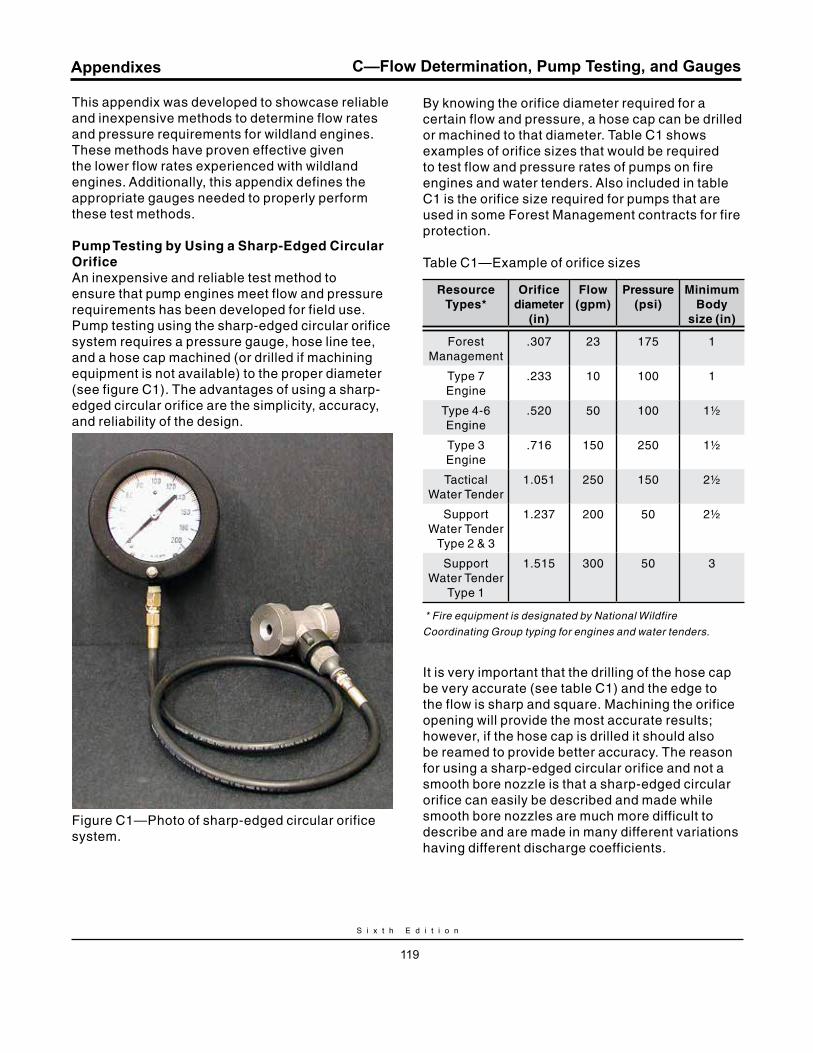
S i x t h E d i t i o n
119
Appendixes C—Flow Determination, Pump Testing, and Gauges
This appendix was developed to showcase reliable and inexpensive methods to determine flow rates and pressure requirements for wildland engines. These methods have proven effective given the lower flow rates experienced with wildland engines. Additionally, this appendix defines the appropriate gauges needed to properly perform these test methods.
Pump Testing by using a Sharp-Edged Circular OrificeAn inexpensive and reliable test method to ensure that pump engines meet flow and pressure requirements has been developed for field use. Pump testing using the sharp-edged circular orifice system requires a pressure gauge, hose line tee, and a hose cap machined (or drilled if machining equipment is not available) to the proper diameter (see figure C1). The advantages of using a sharp-edged circular orifice are the simplicity, accuracy, and reliability of the design.
Figure C1—Photo of sharp-edged circular orifice system.
By knowing the orifice diameter required for a certain flow and pressure, a hose cap can be drilled or machined to that diameter. Table C1 shows examples of orifice sizes that would be required to test flow and pressure rates of pumps on fire engines and water tenders. Also included in table C1 is the orifice size required for pumps that are used in some Forest Management contracts for fire protection.
Table C1—Example of orifice sizes
resource Types*
Orifice diameter
(in)
Flow (gpm)
Pressure (psi)
minimum Body
size (in)
Forest Management
.307 23 175 1
Type 7 Engine
.233 10 100 1
Type 4-6 Engine
.520 50 100 1½
Type 3 Engine
.716 150 250 1½
Tactical Water Tender
1.051 250 150 2½
Support Water Tender
Type 2 & 3
1.237 200 50 2½
Support Water Tender
Type 1
1.515 300 50 3
* Fire equipment is designated by National Wildfire
Coordinating Group typing for engines and water tenders.
It is very important that the drilling of the hose cap be very accurate (see table C1) and the edge to the flow is sharp and square. Machining the orifice opening will provide the most accurate results; however, if the hose cap is drilled it should also be reamed to provide better accuracy. The reason for using a sharp-edged circular orifice and not a smooth bore nozzle is that a sharp-edged circular orifice can easily be described and made while smooth bore nozzles are much more difficult to describe and are made in many different variations having different discharge coefficients.
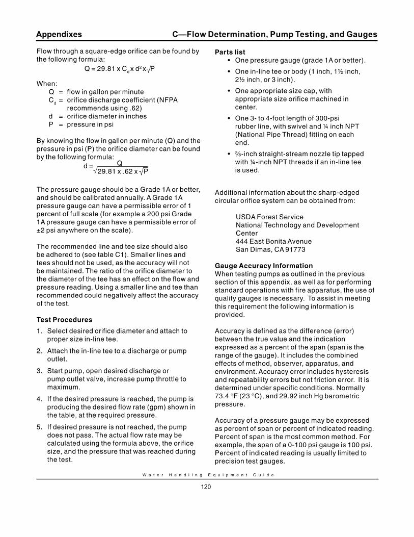
W a t e r H a n d l i n g E q u i p m e n t G u i d e
120
Appendixes
Flow through a square-edge orifice can be found by the following formula:
When: Q = flow in gallon per minute Cd = orifice discharge coefficient (NFPA
recommends using .62) d = orifice diameter in inches P = pressure in psi
By knowing the flow in gallon per minute (Q) and the pressure in psi (P) the orifice diameter can be found by the following formula:
The pressure gauge should be a Grade 1A or better, and should be calibrated annually. A Grade 1A pressure gauge can have a permissible error of 1 percent of full scale (for example a 200 psi Grade 1A pressure gauge can have a permissible error of ±2 psi anywhere on the scale).
The recommended line and tee size should also be adhered to (see table C1). Smaller lines and tees should not be used, as the accuracy will not be maintained. The ratio of the orifice diameter to the diameter of the tee has an effect on the flow and pressure reading. Using a smaller line and tee than recommended could negatively affect the accuracy of the test. Test Procedures
1. Select desired orifice diameter and attach to proper size in-line tee.
2. Attach the in-line tee to a discharge or pump outlet.
3. Start pump, open desired discharge or pump outlet valve, increase pump throttle to maximum.
4. If the desired pressure is reached, the pump is producing the desired flow rate (gpm) shown in the table, at the required pressure.
5. If desired pressure is not reached, the pump does not pass. The actual flow rate may be calculated using the formula above, the orifice size, and the pressure that was reached during the test.
Parts list• One pressure gauge (grade 1A or better).
• One in-line tee or body (1 inch, 1½ inch, 2½ inch, or 3 inch).
• One appropriate size cap, with appropriate size orifice machined in center.
• One 3- to 4-foot length of 300-psi rubber line, with swivel and ¼ inch NPT (National Pipe Thread) fitting on each end.
• a-inch straight-stream nozzle tip tapped with ¼-inch NPT threads if an in-line tee is used.
Additional information about the sharp-edged circular orifice system can be obtained from:
USDA Forest Service National Technology and Development Center 444 East Bonita Avenue San Dimas, CA 91773
Gauge Accuracy InformationWhen testing pumps as outlined in the previous section of this appendix, as well as for performing standard operations with fire apparatus, the use of quality gauges is necessary. To assist in meeting this requirement the following information is provided.
Accuracy is defined as the difference (error) between the true value and the indication expressed as a percent of the span (span is the range of the gauge). It includes the combined effects of method, observer, apparatus, and environment. Accuracy error includes hysteresis and repeatability errors but not friction error. It is determined under specific conditions. Normally 73.4 °F (23 °C), and 29.92 inch Hg barometric pressure.
Accuracy of a pressure gauge may be expressed as percent of span or percent of indicated reading. Percent of span is the most common method. For example, the span of a 0-100 psi gauge is 100 psi. Percent of indicated reading is usually limited to precision test gauges.
C—Flow Determination, Pump Testing, and Gauges
d = Q 29.81 x .62 x P
Q = 29.81 x Cd x d2 x P
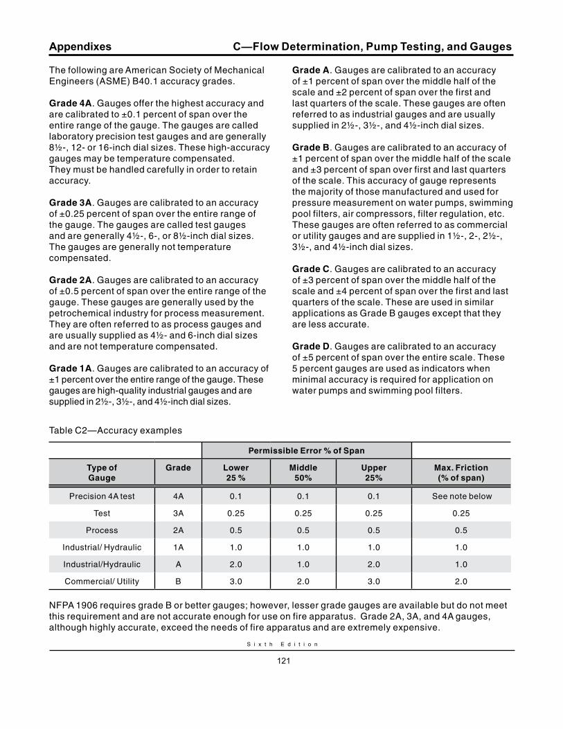
S i x t h E d i t i o n
121
Appendixes
The following are American Society of Mechanical Engineers (ASME) B40.1 accuracy grades.
Grade 4A. Gauges offer the highest accuracy and are calibrated to ±0.1 percent of span over the entire range of the gauge. The gauges are called laboratory precision test gauges and are generally 8½-, 12- or 16-inch dial sizes. These high-accuracy gauges may be temperature compensated. They must be handled carefully in order to retain accuracy.
Grade 3A. Gauges are calibrated to an accuracy of ±0.25 percent of span over the entire range of the gauge. The gauges are called test gauges and are generally 4½-, 6-, or 8½-inch dial sizes. The gauges are generally not temperature compensated.
Grade 2A. Gauges are calibrated to an accuracy of ±0.5 percent of span over the entire range of the gauge. These gauges are generally used by the petrochemical industry for process measurement. They are often referred to as process gauges and are usually supplied as 4½- and 6-inch dial sizes and are not temperature compensated.
Grade 1A. Gauges are calibrated to an accuracy of ±1 percent over the entire range of the gauge. These gauges are high-quality industrial gauges and are supplied in 2½-, 3½-, and 4½-inch dial sizes.
Grade A. Gauges are calibrated to an accuracy of ±1 percent of span over the middle half of the scale and ±2 percent of span over the first and last quarters of the scale. These gauges are often referred to as industrial gauges and are usually supplied in 2½-, 3½-, and 4½-inch dial sizes.
Grade B. Gauges are calibrated to an accuracy of ±1 percent of span over the middle half of the scale and ±3 percent of span over first and last quarters of the scale. This accuracy of gauge represents the majority of those manufactured and used for pressure measurement on water pumps, swimming pool filters, air compressors, filter regulation, etc. These gauges are often referred to as commercial or utility gauges and are supplied in 1½-, 2-, 2½-, 3½-, and 4½-inch dial sizes.
Grade C. Gauges are calibrated to an accuracy of ±3 percent of span over the middle half of the scale and ±4 percent of span over the first and last quarters of the scale. These are used in similar applications as Grade B gauges except that they are less accurate.
Grade D. Gauges are calibrated to an accuracy of ±5 percent of span over the entire scale. These 5 percent gauges are used as indicators when minimal accuracy is required for application on water pumps and swimming pool filters.
C—Flow Determination, Pump Testing, and Gauges
Table C2—Accuracy examples
Permissible Error % of Span
Type of Gauge
Grade Lower 25 %
middle 50%
upper 25%
max. Friction (% of span)
Precision 4A test 4A 0.1 0.1 0.1 See note below
Test 3A 0.25 0.25 0.25 0.25
Process 2A 0.5 0.5 0.5 0.5
Industrial/ Hydraulic 1A 1.0 1.0 1.0 1.0
Industrial/Hydraulic A 2.0 1.0 2.0 1.0
Commercial/ Utility B 3.0 2.0 3.0 2.0
NFPA 1906 requires grade B or better gauges; however, lesser grade gauges are available but do not meet this requirement and are not accurate enough for use on fire apparatus. Grade 2A, 3A, and 4A gauges, although highly accurate, exceed the needs of fire apparatus and are extremely expensive.
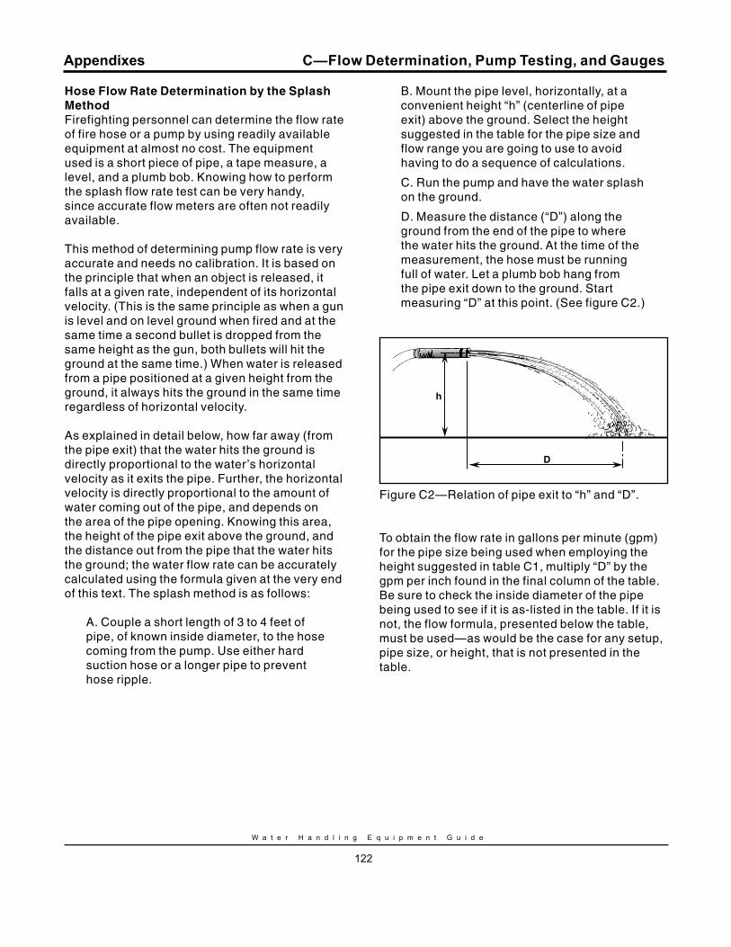
W a t e r H a n d l i n g E q u i p m e n t G u i d e
122
Appendixes
Hose Flow rate Determination by the Splash methodFirefighting personnel can determine the flow rate of fire hose or a pump by using readily available equipment at almost no cost. The equipment used is a short piece of pipe, a tape measure, a level, and a plumb bob. Knowing how to perform the splash flow rate test can be very handy, since accurate flow meters are often not readily available.
This method of determining pump flow rate is very accurate and needs no calibration. It is based on the principle that when an object is released, it falls at a given rate, independent of its horizontal velocity. (This is the same principle as when a gun is level and on level ground when fired and at the same time a second bullet is dropped from the same height as the gun, both bullets will hit the ground at the same time.) When water is released from a pipe positioned at a given height from the ground, it always hits the ground in the same time regardless of horizontal velocity.
As explained in detail below, how far away (from the pipe exit) that the water hits the ground is directly proportional to the water’s horizontal velocity as it exits the pipe. Further, the horizontal velocity is directly proportional to the amount of water coming out of the pipe, and depends on the area of the pipe opening. Knowing this area, the height of the pipe exit above the ground, and the distance out from the pipe that the water hits the ground; the water flow rate can be accurately calculated using the formula given at the very end of this text. The splash method is as follows:
A. Couple a short length of 3 to 4 feet of pipe, of known inside diameter, to the hose coming from the pump. Use either hard suction hose or a longer pipe to prevent hose ripple.
B. Mount the pipe level, horizontally, at a convenient height “h” (centerline of pipe exit) above the ground. Select the height suggested in the table for the pipe size and flow range you are going to use to avoid having to do a sequence of calculations.
C. Run the pump and have the water splash on the ground.
D. Measure the distance (“D”) along the ground from the end of the pipe to where the water hits the ground. At the time of the measurement, the hose must be running full of water. Let a plumb bob hang from the pipe exit down to the ground. Start measuring “D” at this point. (See figure C2.)
D
h
Figure C2—Relation of pipe exit to “h” and “D”.
To obtain the flow rate in gallons per minute (gpm) for the pipe size being used when employing the height suggested in table C1, multiply “D” by the gpm per inch found in the final column of the table. Be sure to check the inside diameter of the pipe being used to see if it is as-listed in the table. If it is not, the flow formula, presented below the table, must be used—as would be the case for any setup, pipe size, or height, that is not presented in the table.
C—Flow Determination, Pump Testing, and Gauges
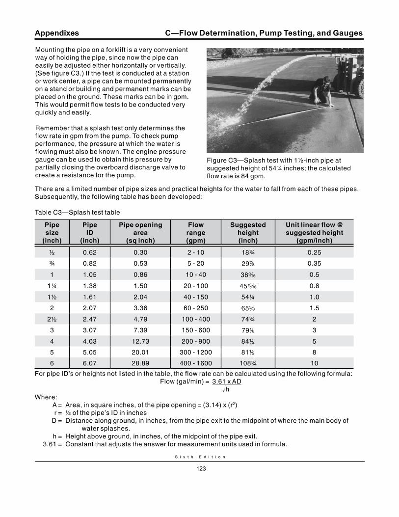
S i x t h E d i t i o n
123
Appendixes
Mounting the pipe on a forklift is a very convenient way of holding the pipe, since now the pipe can easily be adjusted either horizontally or vertically. (See figure C3.) If the test is conducted at a station or work center, a pipe can be mounted permanently on a stand or building and permanent marks can be placed on the ground. These marks can be in gpm. This would permit flow tests to be conducted very quickly and easily.
Remember that a splash test only determines the flow rate in gpm from the pump. To check pump performance, the pressure at which the water is flowing must also be known. The engine pressure gauge can be used to obtain this pressure by partially closing the overboard discharge valve to create a resistance for the pump.
Figure C3—Splash test with 1½-inch pipe at suggested height of 54¼ inches; the calculated flow rate is 84 gpm.
There are a limited number of pipe sizes and practical heights for the water to fall from each of these pipes. Subsequently, the following table has been developed:
Table C3—Splash test table
Pipe size
(inch)
Pipe ID
(inch)
Pipe opening area
(sq inch)
Flow range (gpm)
Suggested height (inch)
unit linear flow @ suggested height
(gpm/inch)
½ 0.62 0.30 2 - 10 18¾ 0.25
¾ 0.82 0.53 5 - 20 29d 0.35
1 1.05 0.86 10 - 40 38b 0.5
1¼ 1.38 1.50 20 - 100 45m 0.8
1½ 1.61 2.04 40 - 150 54¼ 1.0
2 2.07 3.36 60 - 250 65a 1.5
2½ 2.47 4.79 100 - 400 74¾ 2
3 3.07 7.39 150 - 600 798 3
4 4.03 12.73 200 - 900 84½ 5
5 5.05 20.01 300 - 1200 81½ 8
6 6.07 28.89 400 - 1600 108¾ 10
For pipe ID’s or heights not listed in the table, the flow rate can be calculated using the following formula: Flow (gal/min) = 3.61 x AD hWhere: A = Area, in square inches, of the pipe opening = (3.14) x (r2) r = ½ of the pipe’s ID in inches D = Distance along ground, in inches, from the pipe exit to the midpoint of where the main body of
water splashes. h = Height above ground, in inches, of the midpoint of the pipe exit. 3.61 = Constant that adjusts the answer for measurement units used in formula.
C—Flow Determination, Pump Testing, and Gauges

S i x t h E d i t i o n
125
Appendixes
Service Test Pressure ProcedureLong-term maintenance includes testing, repair or replacement of impaired hose, cleaning and drying, and proper long-term storage. Service testing is performed in order to determine if hose is suitable to continue in use.
Before subjecting any hose to a hydrostatic pressure test, visual examination should be performed. Identify and remove damaged hose from the test area.
Safety in testingWhen conducting a hose test involving high pressures, there is a potential for serious accidents. Follow all recommended procedures. Be careful and use common sense.
General safety measuresCouplings mounted crooked on the hose are easier to find when the hose is charged. It is also more dangerous.
When testing, personnel should never stand: (1) in front of the free end of the hose, (2) on the right side of the hose, (3) closer than 15 feet on the left side of the hose, or (4) straddle a hose in the test layout during the test. Left is referenced when facing the free end of the hose, opposite the pressure source. Wear appropriate PPE, including eye protection.
Air is a compressible substanceIn performing Service Pressure Tests, remove all air from the hose before the nozzle or end cap is closed and the pressure is raised. Air is a compressible substance and when greatly compressed, the hose may burst at a pinpoint. In addition, the hose may whip around violently if the pressure is released suddenly, such as when a hose bursts. A blown-off coupling or an expansion ring can act as a projectile, resulting in serious injury or damage to property.
retesting recoupled hoseRetesting repaired or recoupled fire hose can be dangerous. Hose that has been repaired or recoupled should be retested at a test pressure of at least 50 percent greater than the service test pressure.
Test setupProvide a test area that will allow connection of the hydrostatic test equipment to an adequate water source. Only use water to pressure test fire hose. The surface of the test area should be level, smooth, and free of any materials that could damage the hose. The hose should be hydrostatic pressure tested at a minimum of 300 psi.
A hose testing machine or a stationary pump, can be used. Fire engines can be used but it is not recommended. The test hose should be connected to the pump source. If the pump source is a fire engine, it should not be attached to any discharge outlet at, or adjacent to, the pump operator’s position. Shut-off nozzles or test caps should be attached to the far end of the line.
The gauge used to read the test pressure should be certified at least annually.
The water connection on the test valve outlet should be as close to the ground as possible. This will decrease the amount of trapped air at the inlet end when filling the hose for pressure testing.
Hose test sample preparation
Each length of hose to be tested simultaneously should be of the same service test pressure and, collectively, should be considered the hose test layout. The total length of any hose line is limited by the facility/grounds. The hose test layout should be straight without kinks or twists.
Hose that has just been repaired or recoupled should be tested at one length increments only for safety purposes, before being returned to service. Each hose should be marked at the back of each coupling to assist in determining any coupling hose slippage during the test.
D—Service Test for Fire Hose
W a t e r H a n d l i n g E q u i p m e n t G u i d e
126
Appendixes
Test methodWith the inlet valve open and the nozzle or test cap valve open, the pressure should be gradually raised to 45 psi (+ 5 psi tolerance). Fully charge the hose by exhausting all the air out of the hose line. This is done by raising the discharge end of each hose line above the highest point in the system. Close the nozzle or cap slowly, and then the inlet valve should be closed. It is very important that all safety requirements be observed. This includes being very careful to remove all air from the hose before the nozzle or end cap is closed and the pressure is raised.
After pressurizing the hose to 45 psi (+ 5 psi tolerance), check for leakage at the coupling. Tighten with a spanner wrench if necessary. If the coupling appears to be mounted crooked, remove the hose from service.
All personnel, other than those required to perform the remainder of the procedure, should leave the area. The pressure will be raised slowly, over more than 15 seconds, to the service test pressure of a minimum 300 psi and held for 3 minutes (rule of 3’s).
When the service test pressure is achieved, inspect the hose for leaks along the hose length and at the couplings. Test personnel should maintain a distance of at least 15 feet to the left side of the nearest hose line. Left referenced when facing the free end, opposite the pressure source.
After maintaining the service test pressure of 300 psi for 3 minutes, drain the hose lay by shutting down the pump, closing the hose valve, and opening the nozzle or cap.
The marks placed on the hose at the back of the couplings should be observed for coupling slippage. If the coupling has slipped, the hose will have failed the test.
Additional Test requirements For unlined, Hardline, and Suction HoseHardline and suction hose
Hardline hose should be service tested annually, if possible, to 150 percent of its rated working pressure. Hardline hose is rated for a working pressure up to 600 psi and should be service tested at 900 psi. Suction hose should be service tested annually at 50 percent of its proof pressure. Suction hose is rated for a proof pressure up to 100 psi and should be service tested at 50 psi.
In addition, suction hose should be dry vacuum tested annually, if possible, to a vacuum of 25-inches mercury. Attach the hose to a suction source with the free end sealed and connected to an accurate vacuum-measuring instrument. Obtain a vacuum of 25-inches mercury and shut the vacuum pump off. The hose should maintain 25-inches mercury vacuum for 5 minutes, with no loss of vacuum, with the vacuum pump off. Disconnect the hose from the suction source and examine the lining for collapse or failure.
D—Service Test for Fire Hose

S i x t h E d i t i o n
127
Appendixes
Cleaning and dryingAfter use, all hose should be thoroughly cleaned, including hose that has been tested or retested. Hose may be washed and drained outside when necessary, though hose should not be dried in intense direct sunlight. If dirt and dust cannot be removed thoroughly by brushing, or if the hose has come in contact with harmful chemicals, it should be washed. If detergent is used, use a mild solution and rinse thoroughly with clean water.
Wet hose should be drained and completely dried before being placed in service or storage. Hose should not be dried on hot pavements or under intense sunlight. Wet hose, even the lightweight all-synthetic, should be thoroughly dried. Cotton-synthetic hose has been treated for mildew protection but will mildew under prolonged wet conditions. In addition, linen hose must be thoroughly dried immediately after testing to avoid mildew.avoid mildew.
Allow the jacket to dry completely by hanging a 50-foot length of hose from the middle. Hang a 100-foot length of hose from the middle and allow to drain for a minimum of 4 hours. After 4 hours, double the hose and continue to dry for 2 to 3 days or longer as required. The couplings should be off the ground at all times.
Salvaging bad hoseAll hose failing the visual exam and the pressure test should be tagged, repaired, or disposed of as per your agencies guidelines. In the field, tie a knot in failed hose to avoid reuse. If a 100-foot length of hose fails, it can be shortened to 50 feet. If a 50-foot length of hose fails, it should be shortened to no less than 45 feet. Good couplings should be salvaged from discarded hose.
Hose that has been repaired or recoupled should be retested at a test pressure of at least 50 percent greater than the service test pressure.
Place a readily visible, distinguishing mark noting the location of the hose defect, before sending it in. Good couplings should be salvaged from any hose not repairable. For defective couplings, the couplings should be cut from the hose and the hose sent in for recoupling. When a length of hose is recoupled, the tailpiece gasket should be replaced. For additional information, consult the “Fire Equipment Storage and Refurbishing Standards,” National Wildfire Coordinating Group, NFES Number 2249.
D—Service Test for Fire Hose

S i x t h E d i t i o n
129
Appendixes
Centrifugal pumps can be primed with either the pump running or not running. The prime can be taken from the inlet of the pump or the discharge of the pump. For consistently reliable priming a centrifugal pump should be primed from the inlet of the pump when running or from the discharge of the pump when not running.
The four methods that can be used to prime a centrifugal pump are:
1. Prime from suction with pump running. This method primes consistently.
2. Prime from suction with pump not running. This method does not prime consistently.
3. Prime from discharge with pump not running. This method primes consistently.
4. Prime from discharge with pump running. This method does not prime consistently.
The recommended and most commonly used priming method for fire apparatus is to prime from the suction with the pump running. With this method air trapped in the suction plumbing or suction hose is more readily removed. The recommended practice is to set up the draft, operate the primer until water is discharged from the primer, and then start or engage the pump. If the pump is not primed and producing pressure and water flow, operate the primer until pressure and water flow are produced. This keeps running a dry pump to a minimum.
Having 100 percent of the pump discharge pass through check valve(s) is recommended. These check valves eliminate the need for a foot valve on the end of the suction hose and in the pump-to-tank line. They also make priming quicker, easier and consistently reliable by allowing the pump to be primed with a pump to tank valve (No. 2 valve) or a pump to discharge valve (Nos. 3, 4 or 19 valve) open. If 100 percent of the pump discharge does not pass through check valve(s) or the check valve(s) are not working, the discharge valves must be closed until prime is achieved (indicated by pump pressure) and then a discharge valve can be opened slowly to achieve water flow.
Check valves(s) on the discharge-side of the pump can be tested by closing the tank-to-pump valve (No. 1) and the overboard suction valve (No. 8) and opening all discharge valves (Nos. 2, 3, 4, 5, 17, 19), then operating the primer to produce a good vacuum (17-in Hg at sea level or more). If the vacuum does not fall more than 10-in Hg in 5 minutes, the pump discharge check valve(s) are working.
An issue, which will result in poor priming, is a hump in the suction hose or plumbing, every effort should be made to eliminate this situation. If there is a hump in the plumbing that cannot be eliminated, take prime at the top of the hump as well as at the intake to the pump.
Summary of recommendations for optimal priming and pump performance:
1. 100 percent of the pump discharge should pass through check valve(s). This can be accomplished with multiple check valves or with a single check valve on the pump discharge.
2. The prime should be taken at the eye of the impeller or at the top of the inlet to the pump.
3. There should be no humps in the suction hose or plumbing. (If there is a hump in the plumbing, take an additional prime at the top of the hump.)
4. Suction hose should be no longer than necessary.
5. A smooth bell-shaped strainer inlet should be used on the end of the suction hose. Foot valves reduce pump performance and are not needed if check valve(s) are installed on the pump discharge.
6. Set up the draft, operate the primer until water is discharge from the primer, and then start or engage the pump. If the pump is not primed and producing pressure and water flow, operate the primer until pressure and water flow are produced.
E—Priming Centrifugal Pumps

S i x t h E d i t i o n
131
Appendixes F—Centrifugal Pump Cooling Line (Bleed Line) Centrifugal pumps can be run deadhead (without flow) without damage as long as some water is allowed to bleed off (1 to 2 gpm). If a centrifugal pump is al-lowed to deadhead without some water bleeding off, the water in the pump will become very hot and turn to steam resulting in loss of pressure and damage to the packing or mechanical seal. To avoid this problem, all Forest Service standard engines have a bleed rate of 1 to 2 gpm at 150 psi built into the engine plump-ing controlled by the No. 17 valve. The No. 17 valve should never be closed during normal operations except when drafting or relaying and it is assured that water flow will be continuous and an overflowing tank is a serious problem (Forest Service standard engines have a warning label affixed near the No. 17 valve that states “pump damage can occur if valve is closed”).
On Forest Service standard engines bleed flow is through a small diameter tube or a small orifice (about z-inch in diameter) which can easily become plugged. On Forest Service standard engines bleed line water flow can be verified by looking in the fill tower to see if water is flowing out of the bleed line connected to the fill tower.
Bleed line flow can also be verified by the following test if bleed line is not connected to fill tower:
Test for Bleed Line Open
1. Have water in tank.
2. Open valves Nos. 1 and 2 and be sure valve No. 17 is open.
3. Start pump, establish prime and circulate water.
4. Close No. 2 valve, observe pressure of 50 to 100 psi.
5. Close No. 1 valve.
If no drop in pressure, bleed line is not open, if drop in pressure after 30 to 40 seconds bleed line is open.

S i x t h E d i t i o n
133
Appendixes
uSDA Forest Service Specifications/Standards
5100-101 Wrench, spanner, fire hose
5100-102 Couplings, fire and suction hose
5100-105 Strainer, suction hose
5100-107 Fire hose connections and fittings
5100-108 Couplings, lightweight, fire and suction hose
5100-184 Hose suction
5100-185 Hose, rubber, high-pressure w-in
5100-186 Hose, cotton-synthetic jacketed, lined, 1-inch and 1½-inch
5100-187 Hose, fire, lightweight synthetic, type 1 & type 2, lined, woven jacket, 1 inch and 1½ inch
5100-190 Threads, gaskets, and rocker lugs, connections and fittings, fire hose
5100-238 Shut-off, valve, ball
5100-239 Nozzle with shut-off, combination barrel
5100-240 Nozzle, twin tip, shut-off, 1-in base
5100-241 Nozzle, shut-off
5100-242 Nozzle, screw-tip, 1½-inch inlet
5100-243 Nozzle, garden hose
5100-244 Nozzle tips, straight-stream and spray
5100-245 Clamp, fire hose, shut-off
5100-256 Pump, fire, backpack, hand-operated
5100-273 Pumper, engine-driven
5100-274 Pumper, lightweight, portable
5100-275 Pumper, portable, floating
5100-380 Valve, wye
5100-382 Valve, check and bleeder
5100-383 Valve, foot, with strainer
5100-01 Spark arresters for internal combustion engines
National Fire Protection Association (NFPA), Inc. StandardsNFPA 1901 Standards for Automotive Fire
Apparatus
NFPA 1906 Standard for Wildland Fire Apparatus
NFPA 1961 Standard for Fire Hose
NFPA 1962 Standard for the Inspection, Care and Use of Fire Hose, Couplings, and Nozzles and the Service Testing of Fire Hose
NFPA 1963 Standard for Fire Hose Connections
NFPA 1964 Standard for Spray Nozzles
NFPA 1965 Standard for Fire Hose Appliances
G—Specifications and Standards

S i x t h E d i t i o n
135
Appendixes
The following conversion factors are provided for common measurements encountered in the wildland fire agencies.
vOLumE (CAPACITy) u.S. mEASurE
One hose length = 100 feet
s-inch ID = 1.6 gallons
¾-inch ID = 2.3 gallons
1-inch ID = 4.1 gallons
1½-inch ID = 9.2 gallons
1¾-inch ID = 12.5 gallons
Tank size (gallons)
Rectangle = Length x width x height (inches) x 0.00433
Cylinder = 3.14 x diameter squared x height (or length) (inches) x 0.00108
WEIGHT
1 gallon of water at 20 °C (68 °F) = 8.3 pounds
PrESSurE
1 foot of water head (column of water)= approx. ½ psi (.433 psi)
1 psi = approx. 2 feet of water head (2.31 feet )
1 psi = approx. 2 inch Hg (2.04 inch Hg)
1 inch of Hg = approx. ½ psi (.491 psi)
Atmospheric pressure = 14.696 psi @ sea level (or 29.92 inch Hg)
1,000-foot increase in elevation = approx.½ psi decrease in atmospheric pressure
DrAFT
1 inch of mercury = approx. 1-foot lift (1.135 ft)
1,000-foot increase in elevation = 1-foot loss in suction lift capability
DrAFTING GuIDELINES
Elevation Suction Lift (feet) Practical
Sea level 22
2,000 feet 20
4,000 feet 18
8,000 feet 14
H—Conversion Factors

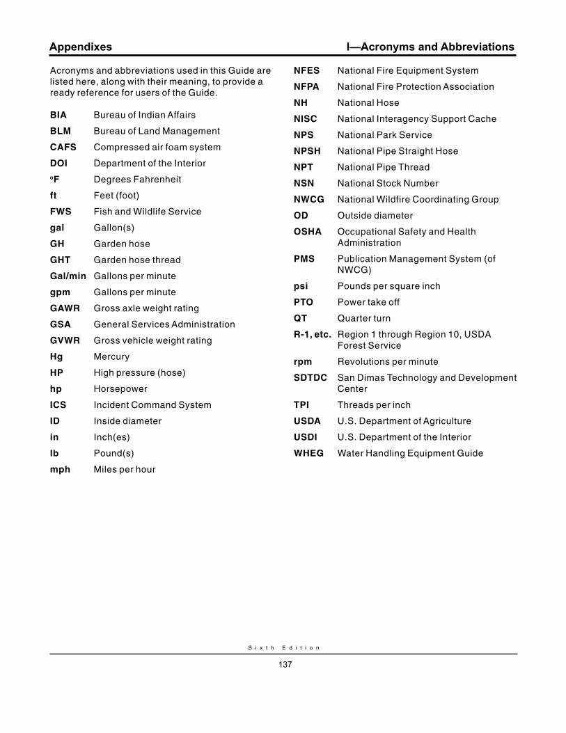
S i x t h E d i t i o n
137
Appendixes
Acronyms and abbreviations used in this Guide are listed here, along with their meaning, to provide a ready reference for users of the Guide.
BIA Bureau of Indian Affairs
BLm Bureau of Land Management
CAFS Compressed air foam system
DOI Department of the InterioroF Degrees Fahrenheit
ft Feet (foot)
FWS Fish and Wildlife Service
gal Gallon(s)
GH Garden hose
GHT Garden hose thread
Gal/min Gallons per minute
gpm Gallons per minute
GAWr Gross axle weight rating
GSA General Services Administration
GvWr Gross vehicle weight rating
Hg Mercury
HP High pressure (hose)
hp Horsepower
ICS Incident Command System
ID Inside diameter
in Inch(es)
lb Pound(s)
mph Miles per hour
NFES National Fire Equipment System
NFPA National Fire Protection Association
NH National Hose
NISC National Interagency Support Cache
NPS National Park Service
NPSH National Pipe Straight Hose
NPT National Pipe Thread
NSN National Stock Number
NWCG National Wildfire Coordinating Group
OD Outside diameter
OSHA Occupational Safety and Health Administration
PmS Publication Management System (of NWCG)
psi Pounds per square inch
PTO Power take off
qT Quarter turn
r-1, etc. Region 1 through Region 10, USDA Forest Service
rpm Revolutions per minute
SDTDC San Dimas Technology and Development Center
TPI Threads per inch
uSDA U.S. Department of Agriculture
uSDI U.S. Department of the Interior
WHEG Water Handling Equipment Guide
I—Acronyms and Abbreviations

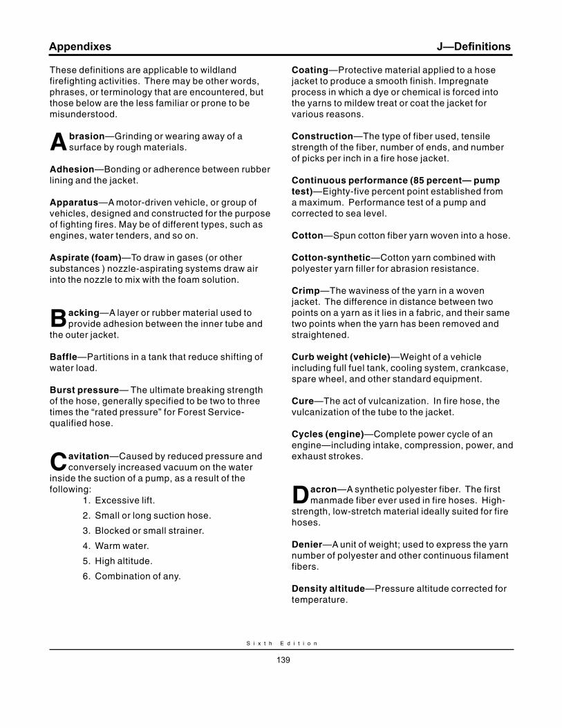
S i x t h E d i t i o n
139
Appendixes
These definitions are applicable to wildland firefighting activities. There may be other words, phrases, or terminology that are encountered, but those below are the less familiar or prone to be misunderstood.
Abrasion—Grinding or wearing away of a surface by rough materials.
Adhesion—Bonding or adherence between rubber lining and the jacket.
Apparatus—A motor-driven vehicle, or group of vehicles, designed and constructed for the purpose of fighting fires. May be of different types, such as engines, water tenders, and so on. Aspirate (foam)—To draw in gases (or other substances ) nozzle-aspirating systems draw air into the nozzle to mix with the foam solution.
Backing—A layer or rubber material used to provide adhesion between the inner tube and
the outer jacket.
Baffle—Partitions in a tank that reduce shifting of water load.
Burst pressure— The ultimate breaking strength of the hose, generally specified to be two to three times the “rated pressure” for Forest Service-qualified hose.
Cavitation—Caused by reduced pressure and conversely increased vacuum on the water
inside the suction of a pump, as a result of the following: 1. Excessive lift.
2. Small or long suction hose.
3. Blocked or small strainer.
4. Warm water.
5. High altitude.
6. Combination of any.
Coating—Protective material applied to a hose jacket to produce a smooth finish. Impregnate process in which a dye or chemical is forced into the yarns to mildew treat or coat the jacket for various reasons.
Construction—The type of fiber used, tensile strength of the fiber, number of ends, and number of picks per inch in a fire hose jacket.
Continuous performance (85 percent— pump test)—Eighty-five percent point established from a maximum. Performance test of a pump and corrected to sea level.
Cotton—Spun cotton fiber yarn woven into a hose.
Cotton-synthetic—Cotton yarn combined with polyester yarn filler for abrasion resistance.
Crimp—The waviness of the yarn in a woven jacket. The difference in distance between two points on a yarn as it lies in a fabric, and their same two points when the yarn has been removed and straightened.
Curb weight (vehicle)—Weight of a vehicle including full fuel tank, cooling system, crankcase, spare wheel, and other standard equipment.
Cure—The act of vulcanization. In fire hose, the vulcanization of the tube to the jacket.
Cycles (engine)—Complete power cycle of an engine—including intake, compression, power, and exhaust strokes.
Dacron—A synthetic polyester fiber. The first manmade fiber ever used in fire hoses. High-
strength, low-stretch material ideally suited for fire hoses.
Denier—A unit of weight; used to express the yarn number of polyester and other continuous filament fibers.
Density altitude—Pressure altitude corrected for temperature.
J—Definitions
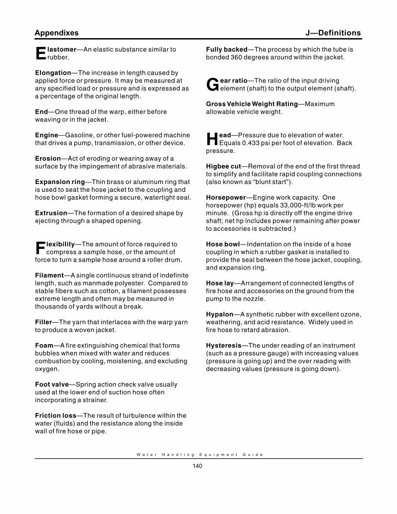
W a t e r H a n d l i n g E q u i p m e n t G u i d e
140
Appendixes
Elastomer—An elastic substance similar to rubber.
Elongation—The increase in length caused by applied force or pressure. It may be measured at any specified load or pressure and is expressed as a percentage of the original length.
End—One thread of the warp, either before weaving or in the jacket.
Engine—Gasoline, or other fuel-powered machine that drives a pump, transmission, or other device.
Erosion—Act of eroding or wearing away of a surface by the impingement of abrasive materials.
Expansion ring—Thin brass or aluminum ring that is used to seat the hose jacket to the coupling and hose bowl gasket forming a secure, watertight seal.
Extrusion—The formation of a desired shape by ejecting through a shaped opening.
Flexibility—The amount of force required to compress a sample hose, or the amount of
force to turn a sample hose around a roller drum.
Filament—A single continuous strand of indefinite length, such as manmade polyester. Compared to stable fibers such as cotton, a filament possesses extreme length and often may be measured in thousands of yards without a break.
Filler—The yarn that interlaces with the warp yarn to produce a woven jacket.
Foam—A fire extinguishing chemical that forms bubbles when mixed with water and reduces combustion by cooling, moistening, and excluding oxygen.
Foot valve—Spring action check valve usually used at the lower end of suction hose often incorporating a strainer.
Friction loss—The result of turbulence within the water (fluids) and the resistance along the inside wall of fire hose or pipe.
Fully backed—The process by which the tube is bonded 360 degrees around within the jacket.
Gear ratio—The ratio of the input driving element (shaft) to the output element (shaft).
Gross vehicle Weight rating—Maximum allowable vehicle weight.
Head—Pressure due to elevation of water. Equals 0.433 psi per foot of elevation. Back
pressure.
Higbee cut—Removal of the end of the first thread to simplify and facilitate rapid coupling connections (also known as “blunt start”).
Horsepower—Engine work capacity. One horsepower (hp) equals 33,000-ft/lb work per minute. (Gross hp is directly off the engine drive shaft; net hp includes power remaining after power to accessories is subtracted.)
Hose bowl—Indentation on the inside of a hose coupling in which a rubber gasket is installed to provide the seal between the hose jacket, coupling, and expansion ring.
Hose lay—Arrangement of connected lengths of fire hose and accessories on the ground from the pump to the nozzle.
Hypalon—A synthetic rubber with excellent ozone, weathering, and acid resistance. Widely used in fire hose to retard abrasion.
Hysteresis—The under reading of an instrument (such as a pressure gauge) with increasing values (pressure is going up) and the over reading with decreasing values (pressure is going down).
J—Definitions
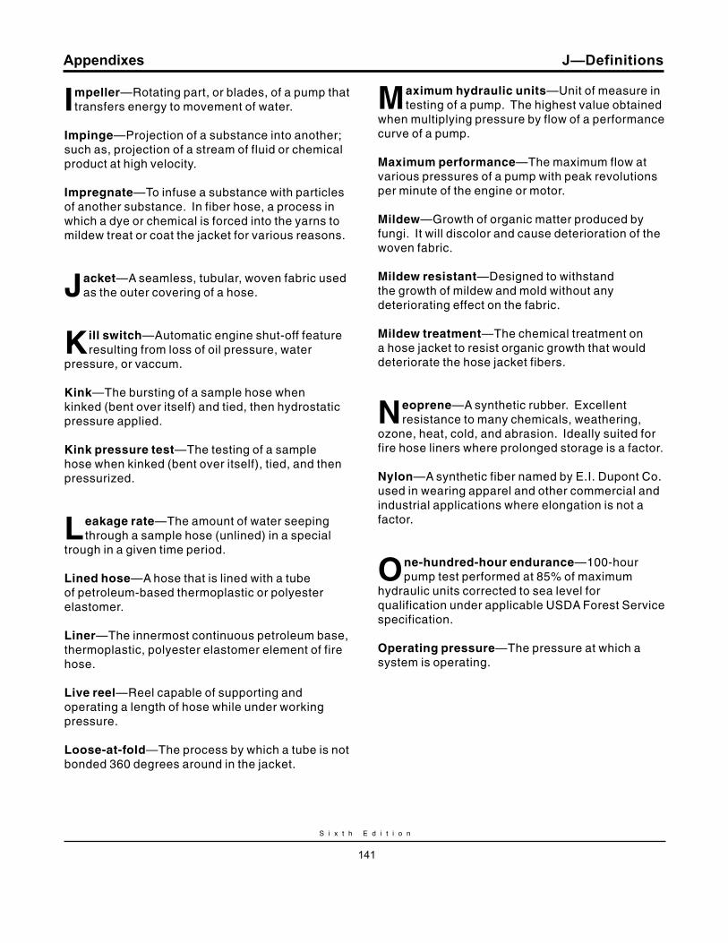
S i x t h E d i t i o n
141
Appendixes
Impeller—Rotating part, or blades, of a pump that transfers energy to movement of water.
Impinge—Projection of a substance into another; such as, projection of a stream of fluid or chemical product at high velocity.
Impregnate—To infuse a substance with particles of another substance. In fiber hose, a process in which a dye or chemical is forced into the yarns to mildew treat or coat the jacket for various reasons.
Jacket—A seamless, tubular, woven fabric used as the outer covering of a hose.
Kill switch—Automatic engine shut-off feature resulting from loss of oil pressure, water
pressure, or vaccum.
Kink—The bursting of a sample hose when kinked (bent over itself) and tied, then hydrostatic pressure applied.
Kink pressure test—The testing of a sample hose when kinked (bent over itself), tied, and then pressurized.
Leakage rate—The amount of water seeping through a sample hose (unlined) in a special
trough in a given time period.
Lined hose—A hose that is lined with a tube of petroleum-based thermoplastic or polyester elastomer.
Liner—The innermost continuous petroleum base, thermoplastic, polyester elastomer element of fire hose.
Live reel—Reel capable of supporting and operating a length of hose while under working pressure.
Loose-at-fold—The process by which a tube is not bonded 360 degrees around in the jacket.
maximum hydraulic units—Unit of measure in testing of a pump. The highest value obtained
when multiplying pressure by flow of a performance curve of a pump.
maximum performance—The maximum flow at various pressures of a pump with peak revolutions per minute of the engine or motor.
mildew—Growth of organic matter produced by fungi. It will discolor and cause deterioration of the woven fabric.
mildew resistant—Designed to withstand the growth of mildew and mold without any deteriorating effect on the fabric.
mildew treatment—The chemical treatment on a hose jacket to resist organic growth that would deteriorate the hose jacket fibers.
Neoprene—A synthetic rubber. Excellent resistance to many chemicals, weathering,
ozone, heat, cold, and abrasion. Ideally suited for fire hose liners where prolonged storage is a factor.
Nylon—A synthetic fiber named by E.I. Dupont Co. used in wearing apparel and other commercial and industrial applications where elongation is not a factor.
One-hundred-hour endurance—100-hour pump test performed at 85% of maximum
hydraulic units corrected to sea level for qualification under applicable USDA Forest Service specification.
Operating pressure—The pressure at which a system is operating.
J—Definitions
W a t e r H a n d l i n g E q u i p m e n t G u i d e
142
Appendixes
Pick—Circular yarn woven between longitudinal warp ends that form a pick on one turn of the
finished jacket.
Polyester—A synthetic material either spun or filament. Can be used in both the warp and filler yarn in fire hose.
Polyethylene—Any of various partially crystalline lightweight thermoplastics that are resistant to chemicals and moisture, have good insulating properties, and are used especially in packaging, insulation and sometimes for wildland engine water tanks.
Polypropylene—A copolymer plastic, usually black, that is strong, ultraviolet resistant, not effected by chemicals and a good choice for wildland engine water tanks.
Polyurethane—This type plastic normally is used for round molded tanks, is not ultraviolet resistant, a poor choice for fire apparatus.
Power take-off—An output shaft on an engine, transmission, or transfer case of a motorized vehicle that delivers engine power to auxiliary equipment.
Priming—Filling pump with water when pump is taking water not under a pressure head. Necessary for centrifugal pumps.
Pump performance value—85% of maximum hydraulic units. (Also same as qualified rating. USDA Forest Service specification.)
qualified rating—Same value as pump performance value (USDA Forest Service
standard).
rated Pressure—The maximum “operating pressure” of a component or system. Also
known as “working pressure” in Forest Service specifications.
retardant (fire)—A substance that reduces or inhibits flammability of combustible material by chemical or physical action.
rise—The height hose lifts from its original flat position once hydrostatic pressure is applied.
Service test pressure—The pressure applied to a hose during periodic testing to determine if
the hose can remain in service.
Slip-on unit—A self-contained unit including an auxiliary engine driven pump, piping, a tank, and hose storage that is designed to be placed on a truck chassis, utility bed, flat bed, or trailer. Such units can typically be attached and removed from the vehicle with a minimum amount of time and effort.
Spun yarn—A textile yarn spun and twisted from staple-length fiber, either natural or synthetic.
Suppressant—Agent that extinguishes the flaming and glowing phases of combustion by direct application to the burning fuel. (Water is a suppressant agent.)
Surge—Rapid increase in flow resulting in rise in pressure.
Tandem—One behind another. (In firefighting operation, a relay operation with short lines
between pumps.)
Twist—The twisting of a hose when hydrostatic pressure is applied. The twisting is either left or right as observed in the direction of flow.
J—Definitions
S i x t h E d i t i o n
143
Appendixes
uniform leakage—The wetting and close up period of a dry unlined hose.
unlined hose—A woven hose that does not incorporate a tube. Designed to seep, and manufactured of linen yarn. Normally used as emergency hose, but used in wildland fires due to its resistance to hot spots that would burn through other types of hose.
uSDA qualification—The purpose of the qualification process is to determine if a manufacturer’s product conforms to USDA Forest Service specifications. For example, the qualification of pumps includes a visual inspection, a priming test, a drafting test, an engine test, an endurance performance test, a spark arrester test, and a sound test. Testing and evaluation is conducted by the government at the expense of the contractor. Once a product is determined to meet the minimum specification requirements, the product is assigned a Qualified Products List (QPL) number and is added to the QPL. The QPL is a USDA Forest Service list of products that have been examined, tested, and have satisfied all applicable qualification requirements and may be used by any interested party.
Warp—The amount of deviation from a straight line when the hose is hydrostatically tested;
usually expressed in inches.
Water extraction—The pH content of a hose jacket determined after boiling in distilled water in a laboratory test.
Water hammer—The series of shocks, sounding like hammer blows, produced by suddenly reducing the flow of a fluid in a pipe or hose such as when a valve is rapidly closed.
Wetting agent—Detergent type chemical that when added to water reduces surface tension and increases penetration into fuels.
Wet water—Water treated with wetting agent.
Wheel base —Distance from centerlines of front axle to rear axle of a motor-driven vehicle or center of tandem axles
Working pressure—The maximum “operating pressure” of a component or system. Identified as “WP” on Forest Service-qualified fire hose. Also known as “rated pressure.”
yarn number (cotton)—A conventional relative measure of fineness as applied to yarns.
Coarse yarns have low numbers and fine yarns have high numbers.
J—Definitions

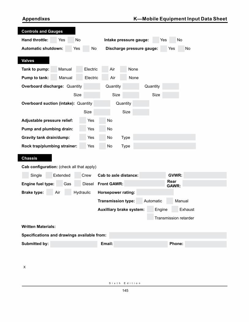
Controls and Gauges
Hand throttle: Yes No Intake pressure gauge: Yes No
Automatic shutdown: Yes No Discharge pressure gauge: Yes No
Valves
Tank to pump: Manual Electric Air None
Pump to tank: Manual Electric Air None
Overboard discharge: Quantity Quantity Quantity
Size Size Size
Overboard suction (intake): Quantity Quantity
Size Size
Adjustable pressure relief: Yes No
Pump and plumbing drain: Yes No
Gravity tank drain/dump: Yes No Type
Rock trap/plumbing strainer: Yes No Type
Chassis
Cab configuration: (check all that apply)
Single Extended Crew Cab to axle distance: GVWR:
Engine fuel type: Gas Diesel Front GAWR: Rear
Brake type: Air Hydraulic Horsepower rating: GAWR:
Transmission type: Automatic Manual
Auxilliary brake system: Engine Exhaust
Transmission retarder
Written Materials:
Specifications and drawings available from:
Submitted by: Email: Phone:
X
S i x t h E d i t i o n
145
Appendixes K—Mobile Equipment Input Data Sheet
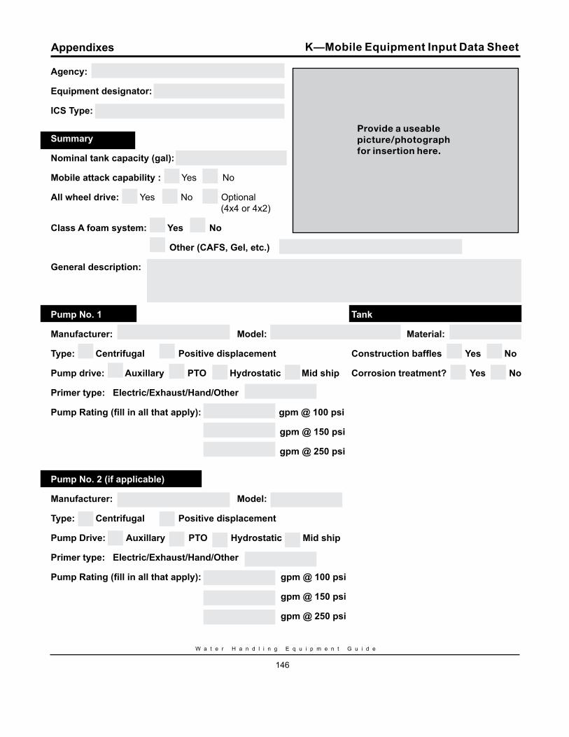
W a t e r H a n d l i n g E q u i p m e n t G u i d e
146
Agency:
Equipment designator:
ICS Type:
Summary
Nominal tank capacity (gal):
Mobile attack capability : Yes No
All wheel drive: Yes No Optional (4x4 or 4x2)
Class A foam system: Yes No
Other (CAFS, Gel, etc.)
General description:
Pump No. 1 Tank
Manufacturer: Model: Material:
Type: Centrifugal Positive displacement Construction baffles Yes No
Pump drive: Auxillary PTO Hydrostatic Mid ship Corrosion treatment? Yes No
Primer type: Electric/Exhaust/Hand/Other
Pump Rating (fill in all that apply): gpm @ 100 psi
gpm @ 150 psi
gpm @ 250 psi
Pump No. 2 (if applicable)
Manufacturer: Model:
Type: Centrifugal Positive displacement
Pump Drive: Auxillary PTO Hydrostatic Mid ship
Primer type: Electric/Exhaust/Hand/Other
Pump Rating (fill in all that apply): gpm @ 100 psi
gpm @ 150 psi
gpm @ 250 psi
Appendixes K—Mobile Equipment Input Data Sheet
Provide a useablepicture/photographfor insertion here.
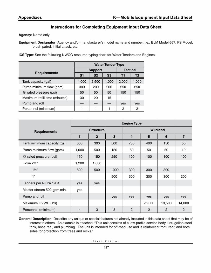
S i x t h E d i t i o n
147
Appendixes K—Mobile Equipment Input Data Sheet
Instructions for Completing Equipment Input Data Sheet
Agency: Name only
Equipment Designator: Agency and/or manufacturer’s model name and number, i.e., BLM Model 667, FS Model, brush patrol, initial attack, etc.
ICS Type: See the following NWCG resource-typing chart for Water Tenders and Engines.
requirements
Water Tender Type
Support Tactical
S1 S2 S3 T1 T2
Tank capacity (gal) 4,000 2,500 1,000 2,000 1,000
Pump minimum flow (gpm) 300 200 200 250 250
@ rated pressure (psi) 50 50 50 150 150
Maximum refill time (minutes) 30 20 15 — —
Pump and roll — — — yes yes
Personnel (minimum) 1 1 1 2 2
requirements
Engine Type
Structure Wildland
1 2 3 4 5 6 7
Tank minimum capacity (gal) 300 300 500 750 400 150 50
Pump minimum flow (gpm) 1,000 500 150 50 50 50 10
@ rated pressure (psi) 150 150 250 100 100 100 100
Hose 2½” 1,200 1,000
1½” 500 500 1,000 300 300 300
1” 500 300 300 300 200
Ladders per NFPA 1901 yes yes
Master stream 500 gpm min. yes
Pump and roll yes yes yes yes yes
Maximum GVWR (lbs) 26,000 19,500 14,000
Personnel (minimum) 4 3 3 2 2 2 2
General Description: Describe any unique or special features not already included in this data sheet that may be of interest to others. An example is attached: “This unit consists of a low-profile service body, 250-gallon steel tank, hose reel, and plumbing. The unit is intended for off-road use and is reinforced front, rear, and both sides for protection from trees and rocks.”
W a t e r H a n d l i n g E q u i p m e n t G u i d e
148
Appendixes
Equipment Input Data Sheet
The National Wildfire Coordinating Group (NWCG), Equipment Technology Committee, Water Handling Equipment Guide (WHEG) task team requests that the format presented here be used when submitting infor-mation to be added to the next edition of this Guide. This equipment must meet NWCG engine or water ten-der typing requirements (see page 2), be in use cur-rently, and have a set of standards or specifications so that it may be duplicated. Please do not submit infor-mation on apparatus used in a “reserve” capacity or that is no longer in service.
Submit two pictures (300 dpi minimum):
1. Front quarter view, passenger side
2. Rear quarter view, driver side
Additional photos of other variants/options if available (cab configuration, etc)
Tank: Material—i.e., mild steel, stainless steel, poly-propylene, plastic, fiberglass, aluminum.
Controls and Gauges: Automatic shutdown—Does the unit have an automatic shutdown of the pumping system controlled by oil pressure, water temperature, or low water?
valves: Drain/Dump—Are these valves controlled manually, electrically, or pneumatically?
Rock trap/plumbing strainer—Is apparatus equipped with a plumbed strainer/rock trap or an inlet screen on the inlet side of the [ump (excluding any devcie on the suction hose)?
Written materials: Agency name, contact person, mailing address, telephone number, fax num-ber, e-mail address.
K—Mobile Equipment Input Data Sheet


