wakey wakey autonomous alarm robot - university of florida · wakey wakey autonomous alarm robot...
TRANSCRIPT
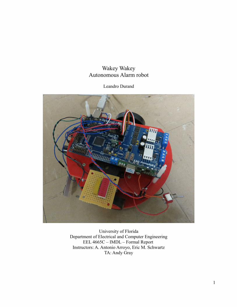
Wakey WakeyAutonomous Alarm robot
Leandro Durand
University of FloridaDepartment of Electrical and Computer Engineering
EEL 4665C – IMDL – Formal Report Instructors: A. Antonio Arroyo, Eric M. Schwartz
TA: Andy Gray
1

ContentsAbstract.........................................................................................................................................3Executive Summary.......................................................................................................................4Introduction ..................................................................................................................................5Integrated System..........................................................................................................................6Mobile Platform.............................................................................................................................7Actuation.........................................................................................................................................8Sensors............................................................................................................................................9Behaviors......................................................................................................................................11Experimental Layout and Results.................................................................................................12Conclusion.....................................................................................................................................13Documentation .............................................................................................................................14Appendices....................................................................................................................................15
2

AbstractSometimes it's hard to wake up in the morning. Multiple alarms can be set or one can use alarms that require the user to solve a puzzle to turn it off, but most of the time, people can get around those and fall back sleep, rendering those alarms ineffective. To fix this issue, a robot was designed to move around and be a moving alarm clock that would force the user to physically get up to turn it off. This is more effective because once the user is out of the bed and up and moving, its harder for them to fall back sleep since they are up.
3

Executive SummaryWakey Wakey is an autonomous robot created to wake me up when all my alarms can't. This is done by giving the system a set time that I want to sleep for and then this robot will act as a moving alarm, so I have to get up, follow it and then turn it off.
Propulsion is provided by 2 hacked servos, with 2 casters (one in the front and the other in the back) for stability. Two bump sensors and 2 sonars were placed in the front for obstacle avoidance and for safety purposes since there is a chance that the user can step on this robot. Inside Wakey Wakey resides the battery pack. On top of this robot lies the rest of the electronics, which include the Epiphany DIY board with all the extra parts, the buzzer, LED circuit and then the switch.
When Wakey is first turned on, the robot will not move. All that it is doing right now is sending a wait signal to the xbee connected to the computer. This is necessary, so the matlab code doesn’t open the file from the dropbox account while it's being uploaded. Once the phone has scanned the QR code and has then uploaded it to the dropbox folder, then the user can hold one of the bump sensors for 2-3 seconds. Th robot will send a ready signal to the laptop and then the laptop will get the data from the dropbox file and based on the value, send different signals to the xbee on the robot. Once this signal is received, then the robot will wait the time specified. After that's done, the robot will go into obstacle avoidance mode.
In obstacle avoidance mode, Wakey will turn on the buzzer and the LED circuit. It will then use the 2 sonars in the front to detect objects in its way and move around them The servos change direction based on the data received from the sonars. If the value obtained from the sonars drops below a certain point, then the robot knows there is something in the way and it will move.
4

IntroductionMy robot idea is an alarm robot. I'm using a mobile platform similar to the one Dr. Arroyo showed in class. It will use two hacked servos and a caster wheel for actuation. It will have 2 sonars, and 2 Bump sensors for obstacle avoidance. It will have LED’s for brightness and to show the state of the robot, and a buzzer to make noise so the user has to get up. It will have a switch for the user to press once they are awake. The special sensor with be a camera, that detect AR tags and and by communication with my laptop, a signal can be sent using xbee's to the Epiphany DYI board to then figure out when to go off. This report will cover in more detail the development of “Wakey Wakey”.
5

Integrated SystemsFor my board, I'm using Tim's Epiphany DIY board because its versatile and very powerful. This acts as the center of the system. The platform consists of 2 hacked servos, 3 bump sensors, an LED circuit, a buzzer, a battery, and an xbee to communicate with my laptop that has another xbee. The data from the phone is sent to my computer and then analyzed and the sent to the Epiphany board.
Fig 1. System Block Diagram
6

Mobile Platform
Fig 2. Platform
The mobile platform is composed of 2 layers. Each one of these layers holds different components. The bottom layers hold the battery, the hacked servos, and the bump sensors. The top layers holds the rest of the electronics. This includes the epiphany board, the LED circuit, the buzzer, the power switch, and the xbee. The sonars are actually stuck between the two layers, allowing the sonars to face forward and not move while the robot moves. For the bump sensors, I used the whiskers method along the front of the robot. In the end, these whiskers were made of out cardboard.
7

Actuation
Fig 3. Servo
Polulu DC motors were meant to be used but after some testing, I realized the servos where better for this kind of scenario. Since the robot will be in a room, the motors were too much. Instead, I'm using hacked servos. The servo Tiny controller within the Epiphany board is being used to move the servos. The robot will remain stationary until it receives the signal to go off. That’s when the servos will be powered and move the robot while it makes all kinds of noises and lights.
8

Sensors
Fig 4. Sonars
Sonars are used to detect obstacles and avoid them. This is necessary for this project so the robot can move until the user turns it off. Two of these sensors were used so I had to do some testing to see how far they can go and how close the can get.
Fig 5. Bump sensors
Bump sensors were also used. They are both used as a switch to start the system and as a way to stop the robot if it gets too close to the user. 5v were applied to one end with the other connected to an interrupt with a pull down resistor. Pressing the switch connected the circuit pulling the interrupt pin high. This is then read in the code and makes the robot stop, because the user got too close and I don’t want the user stepping on the robot while looking for it. This is more of a safety mechanism.
9

Fig 6. Camera
The camera is used as a separate sensor. It is not connected to the robot but it is used to scan the qr codes and then upload them to dropbox account in the form of a txt file. This file is then pulled and used to send data to the robot about how long it should wait before it goes off. This is done through some matlab code I wrote to pull the file only when it receives the signal from the robot. If this is not done, the code has problems dealing with the timing of the file being updated.
10

BehaviorWakey Wakey has two behaviors. One of them is waiting for the phone to update the file using the QR code, and then delaying accordingly. The other behaviors is the autonomous one where it goes around making noise and lights while avoiding obstacles until the user turns it off.
Fig 7. Software Block Diagram
11

Experimental Layouts and ResultsTo make sure the data from the camera worked, The robot was presented with different QR codes, which then were read from the dropbox file, and outputted into a small screen. Next, that data was sent via xbee to the Epiphany DIY board to send figure out how much time it should wait before it starts running.
Due to delays in the xbee's, I had to try out different connections to see what was the average delay and include that in the code. I ran into some issues with my delays because they would either be too short or too long and the robot never moved. For the purposes of demoing the robot, I came to the conclusion that smaller times would be better. So, my delays are now 20 seconds, 30 seconds, 1 minute, 2 minutes, and 5 minutes as the max. This will allow for easy demoing and it should give me enough time to explain the robot, its components, and behaviors while it waits.
12

ConclusionSo far, the biggest issue I had was timing when it comes to pooling the file along with the delay. This was fixed by using a input from the user to tell the robot to start. This is done after the file has been updated so there is no problem with polling a file while its being created. This project could be improved by increasing the speed of the robot so its harder to catch while still maintaining its behavior. Maybe even adding a puzzle when its caught to add to the complexity and to make sure the user is up. I will also try adding a light sensor to change behavior based on the lighting of the room. If it's dark, then the lights are needed for the user to find the robot. If it's bright, then the LED's are not really required and maybe some other device will be used instead.
13

DocumentationEpiphany DIY home page: http://ootbrobotics.com/wiki/ -Header files are located there Maxbotix Sonar EZ1 http://maxbotix.com/documents/MB1010_Datasheet.pdfXbee Series 1 - https://www.sparkfun.com/datasheets/Wireless/Zigbee/XBee-Manual.pdf
14
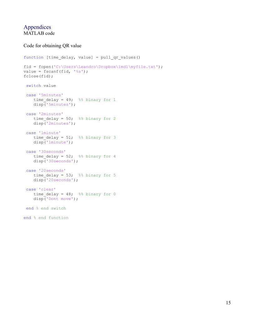
AppendicesMATLAB code
Code for obtaining QR value
function [time_delay, value] = pull_qr_values() fid = fopen('C:\Users\Leandro\Dropbox\imdl\myfile.txt'); value = fscanf(fid, '%s'); fclose(fid); switch value case '5minutes' time_delay = 49; %% binary for 1 disp('5minutes'); case '2minutes' time_delay = 50; %% binary for 2 disp('2minutes'); case '1minute' time_delay = 51; %% binary for 3 disp('1minute'); case '30seconds' time_delay = 52; %% binary for 4 disp('30seconds'); case '20seconds' time_delay = 53; %% binary for 5 disp('20seconds'); case 'clear' time_delay = 48; %% binary for 0 disp('Dont move'); end % end switch end % end function
15

Main function
clear all clc time_delay = 0; %initializing valuesvalue = 0;signal =''; time_delay = uint8(time_delay);value = uint8(value); % //////////// opening the serial port ///////////////// serialport = serial('com8'); set(serialport,'baudrate', 9600); set(serialport, 'databits',8); set(serialport,'stopbits', 1); set(serialport, 'flowcontrol', 'none'); set(serialport, 'terminator', 'CR'); fopen(serialport) % ////////////////////////////////////////////////////// fwrite(serialport, [time_delay]); while(1) signal = fscanf(serialport, '%c', 1); % reads data from xbee on robot (the signal to star) disp('not matched'); % displayed not macthed to show we are still waiting if(strcmp(signal, 'Y')) % compares data from xbee to Y disp('matched'); % if they match, then display match [time_delay, value] = pull_qr_excel; % get data from file time_delay = uint8(time_delay); % format that data fwrite(serialport, [time_delay]); % output the data from the xbee on my computer to the robot endend
16

Atmel code in C/* * Lab.c * * Created: 9/18/2013 1:37:04 PM * Author: Leandro */
#include "Epiphany.h"uint8_t order = 0;uint16_t sonar1;uint16_t sonar2;void move();
void setup(){
//initialize system clock to 32MHzclockInit();
//initialize the real time clockRTC_DelayInit();
//initialize the uart connected to the USB interfaceusbInit(115200);xbeeInit(9600);
//initialize the ADCadcInit();
ATtinyServoInit();
// making pins 0 and 1 on port d pull down resistors activated inputsPORTB.DIRCLR = 0xFF; // sets all of D as inputPORTB.PIN0CTRL |= 0x10;PORTB.PIN1CTRL |= 0x10;
PORTD.DIRSET = 0xFF; // sets all of D as outputs
//global interrupt enablesei();
}
void loop(){
//fscanf(&USB_str,"%c", &order);//fprintf(&Xbee_str,"order received = %c \r\n\r\n",order); //fprintf(&USB_str,"order received = %c \r\n\r\n",order); if (!((PORTB.IN & 0b00000001) == 0b00000001) && !((PORTB.IN & 0b00000010) ==
0b00000010))fprintf(&Xbee_str,"N");
else if (((PORTB.IN & 0b00000001) == 0b00000001) || ((PORTB.IN & 0b00000010) == 0b00000010)){
fprintf(&Xbee_str,"Y");fscanf(&Xbee_str,"%c", &order);if (order == 49) {
/*for(int i = 0; i<5; i++){_delay_ms(600); //5 minutes
17

}*/PORTD.OUTSET = 0x08;_delay_ms(3050); //5 minutesmove();
}else if (order == 50) {
/*for(int i = 0; i<10; i++){_delay_ms(600); //10 minutes
}*/PORTD.OUTSET = 0x08;_delay_ms(1250); //2 minutesmove();
}else if (order == 51) {
/*for(int i = 0; i<15; i++){_delay_ms(600); //15 minutes
}*/PORTD.OUTSET = 0x08;_delay_ms(650); //1 minutesmove();
}else if (order == 52) {
/*for(int i = 0; i<30; i++){_delay_ms(600); //30 minutes
}*/PORTD.OUTSET = 0x08;_delay_ms(350); //30 secondsmove();
}else if (order == 53) {
PORTD.OUTSET = 0x08;_delay_ms(250); //20 secondsmove();
}}
}void move(){
while(1){PORTD.OUTSET = 0x0A; //buzzer and lights outputif (((PORTB.IN & 0b00000001) == 0b00000001) || ((PORTB.IN & 0b00000010) ==
0b00000010)){disableServo(1);disableServo(3);RTC_Delay_ms(5);
}else{
sonar1 = analogRead(0);sonar2 = analogRead(1);
if(sonar1 > 80 && sonar2 >80){setServoPosition(1, -150);setServoPosition(3, 150);RTC_Delay_ms(5);
}else if(sonar1 >80 && sonar2 < 80){
setServoPosition(1, -10);setServoPosition(3, -150);
18

RTC_Delay_ms(5);
}else if(sonar1 < 80 && sonar2 > 80){
setServoPosition(1, 150);setServoPosition(3, 0);RTC_Delay_ms(5);
}else{
setServoPosition(1, 150);setServoPosition(3, -150);RTC_Delay_ms(5);
}}
}}
19