vulnerability of wireless networks to interception · vulnerability of wireless networks to...
TRANSCRIPT

40 Journal of Information Warfare (2004) 3, 2: 40 – 51 ISSN 1445-3312 print/ISSN 1445-3347 online
Vulnerability of Wireless Networks to Interception
David C. Jenn1, Lim Wee Pin2, and Paul P. Sumagaysay3
1Department of Electrical and Computer Engineering Naval Postgraduate School, Monterey, CA
E-mail: [email protected]
2Singapore Ministry of Defense, Singapore
3Lieutenant, United States Navy, Washington, DC
Abstract This paper examines the vulnerability of wireless systems to interception, and provides some simple steps that can be taken to improve security. A commercially available computational electromagnetics software package was used to predict signal levels in complex indoor and urban environments. The simulation results can be used to determine the detection range of the network. Two basic scenarios are presented: (1) indoor-to-outdoor propagation for a local area network operating in a two story building, and (2) a wireless point-to-point link on an airbase. The simulations illustrate some of the unique propagation conditions that occur inside of buildings and in urban areas. This research has identified several possible system weaknesses and suggested some simple, yet effective, methods of improving security. Introduction A variety of wireless systems are used in both the civilian and military sectors. Some reasons for choosing wireless local area networks (WLANs) and point-to-point (PTP) systems over hardwired networks are their real-time information availability, achievable high bandwidths, resilience to failures, and simple and rapid installation (Boerner, 1995; Pahlavan, 1995).
One concern in deploying systems that radiate in free space is the possibility of signals being intercepted by unauthorized users. The first step in the hacking process is to gain unauthorized access to network traffic. In many cases this is most easily accomplished by intercepting wireless signals. Authentication and encryption provide data security. Complex encryption techniques make it difficult for the average person to penetrate the system, however, the algorithms that are built into the network software have been defeated by knowledgeable hackers (Singhal, 2001; Conjungi, 2003). Although wireless security is vastly improved since the first generation systems, the threats continue to grow, and maintaining security is a constant challenge (ITworld, 2004). Predicting and subsequently controlling the electromagnetic radiation is an effective means of securing the network.
In the case of WLANs, even though the power levels involved are low, a person in a public lobby or just outside of a building could conceivably tap into a system in a restricted area. Even for PTP systems that use directive antennas, the antenna illumination area on the ground (i.e., its “footprint”) increases with the range between two network nodes. Additionally, there are unique propagation conditions that occur

Report Documentation Page Form ApprovedOMB No. 0704-0188
Public reporting burden for the collection of information is estimated to average 1 hour per response, including the time for reviewing instructions, searching existing data sources, gathering andmaintaining the data needed, and completing and reviewing the collection of information. Send comments regarding this burden estimate or any other aspect of this collection of information,including suggestions for reducing this burden, to Washington Headquarters Services, Directorate for Information Operations and Reports, 1215 Jefferson Davis Highway, Suite 1204, ArlingtonVA 22202-4302. Respondents should be aware that notwithstanding any other provision of law, no person shall be subject to a penalty for failing to comply with a collection of information if itdoes not display a currently valid OMB control number.
1. REPORT DATE 2004
2. REPORT TYPE N/A
3. DATES COVERED -
4. TITLE AND SUBTITLE Vulnerability of Wireless Networks to Interception
5a. CONTRACT NUMBER
5b. GRANT NUMBER
5c. PROGRAM ELEMENT NUMBER
6. AUTHOR(S) 5d. PROJECT NUMBER
5e. TASK NUMBER
5f. WORK UNIT NUMBER
7. PERFORMING ORGANIZATION NAME(S) AND ADDRESS(ES) Naval Postgraduate School Department of Electrical and ComputerEngineering Monterey, CA 93943
8. PERFORMING ORGANIZATIONREPORT NUMBER
9. SPONSORING/MONITORING AGENCY NAME(S) AND ADDRESS(ES) 10. SPONSOR/MONITOR’S ACRONYM(S)
11. SPONSOR/MONITOR’S REPORT NUMBER(S)
12. DISTRIBUTION/AVAILABILITY STATEMENT Approved for public release, distribution unlimited
13. SUPPLEMENTARY NOTES The original document contains color images.
14. ABSTRACT This paper examines the vulnerability of wireless systems to interception, and provides some simple stepsthat can be taken to improve security. A commercially available computational electromagnetics softwarepackage was used to predict signal levels in complex indoor and urban environments. The simulationresults can be used to determine the detection range of the network. Two basic scenarios are presented: (1)indoor-to-outdoor propagation for a local area network operating in a two story building, and (2) awireless point-to-point link on an airbase. The simulations illustrate some of the unique propagationconditions that occur inside of buildings and in urban areas. This research has identified several possiblesystem weaknesses and suggested some simple, yet effective, methods of improving security.
15. SUBJECT TERMS
16. SECURITY CLASSIFICATION OF: 17. LIMITATION OF ABSTRACT
SAR
18. NUMBEROF PAGES
11
19a. NAME OFRESPONSIBLE PERSON
a. REPORT unclassified
b. ABSTRACT unclassified
c. THIS PAGE unclassified
Standard Form 298 (Rev. 8-98) Prescribed by ANSI Std Z39-18

Vulnerability of Wireless Networks to Interception
Journal of Information Warfare 41
inside of buildings and in urban areas that can enhance signal detection under certain circumstances. Thus, wireless systems are vulnerable to uninvited intruders who could collect sensitive information or possibly even disrupt the computer network by injecting deceptive signals.
Electromagnetic wave propagation modeling in indoor and urban environments is difficult because of the interactions between a large number of scattering objects such as walls and furniture. Modern buildings and furnishings use many materials that affect propagation by attenuation, reflection, and diffraction. Building walls, floors, landscapes, and even passing cars affect the manner in which these signals propagate. The underlying electromagnetic theory is well understood (Balanis, 1989; Molkdar, 1991), and accurate propagation simulations are achievable with sufficient computational resources (i.e., computer processing time and memory) and high-fidelity building models. It is often the lack of knowledge of the materials enclosed in a building wall that limits the accuracy of a simulation, rather than any shortcoming in the electromagnetic analysis. Overview This paper examines the vulnerability of WLAN and PTP systems to interception, and provides some simple steps that can be taken to improve security. A commercially available computational electromagnetics (CEM) software package was used to predict signal levels in complex indoor and urban environments. The simulations assume that the WLAN access point or one of the PTP nodes is transmitting. The simulation outputs are contours of power levels on a grid of observation points that can be used to predict the radiated power distribution of the network. Given the specification of an intercept receiver, it is possible to convert the power contours to detection ranges.
Two basic scenarios are presented, which represent a small fraction of the many cases simulated in the course of the research (Sumagaysay, 2002; Lim, 2003). The first is WLAN indoor-to-outdoor propagation for a two-story building that might be occupied by a small business. The second is a wireless PTP link on an airbase that is used to transmit targeting data to a hangar where it is then disseminated through a local WLAN to the various aircraft being housed. These cases were selected because they illustrate some of the unique propagation effects that can occur in urban areas. Propagation Modeling Radio wave propagation in urban areas is complicated, but it is traditionally attributed to three basic mechanisms: (1) reflection, (2) diffraction, and (3) scattering (Anderson, et al 1995). As a result of these propagation mechanisms, the received signal strength from an access point can be roughly characterized by three nearly independent phenomena of large-scale path loss, large-scale shadowing, and multi-path fading. Network links in urban environments are subjected to severe degradation due to the superposition of many contributions to the three components.
For a narrow band wireless system operating at frequency f, the received power rP from an access point transmitting a power tP with antenna gain tG at range R is given by the Friis equation (Balanis, 1997)
22
2 2 | |(4 )
t t r pr
PG G LGP F
R
λ
π= . (1)

Vulnerability of Wireless Networks to Interception
42 Journal of Information Warfare
The wavelength is /c fλ = where 83 10c = × m/s is the phase velocity in free space. For a WLAN, the user’s antenna gain is assumed to be isotropic (omni-directional),
1rG = . The miscellaneous loss and processing gain factors, L and pG , respectively, are system dependent. The path-gain factor (PGF) F gives the total signal (electric field intensity) at the user’s location relative to the direct free-space signal. The PPF is computed by the software using the given geometry and media electrical parameters. Because the reflecting and diffracting objects are large compared to the wavelength, high-frequency ray-tracing approximations can be applied, as illustrated in Figure 1 (Deschamps, 1972). In addition to the direct path signal, for ray-based propagation modeling, the contributors to the total electric field intensity are the many reflected and diffracted signals that occur in the environment. They arise from the ground and foliage, or buildings and other manmade objects on the ground or in the air. At a given an observation point in space, the total field will be the sum of all of the direct, reflected, and diffracted fields arriving at that point.
ACCESS POINTTRANSMITTER
USER 1
USER 2
USER 3
METAL
GLASS
DIFFRACTION
REFLECTION
TRANSMISSION
REFLECTION
Figure 1: Illustration of some possible ray paths for the simple case of a glass slab and metal wall (top view).
Formulas are available for the reflected and diffracted fields based on geometrical optics (GO) and the geometrical theory of diffraction (GTD) (Balanis, 1989). They incorporate coefficients that linearly relate the reflected and diffracted fields to the incident fields at the reflection and diffraction points, respectively. In the case of reflection, the traditional Fresnel coefficients for planar boundaries can be used (Balanis, 1989). Specular (mirror-like) reflections must satisfy Snell’s law: the angle of reflection equals the angle of incidence. Edge-diffracted fields also follow known trajectories; they lie on a cone whose axis is coincident with the diffracting edge and half angle is determined by the angle of the incident ray with the edge (Keller 1962). The formulas for the reflection and diffraction coefficients depend on the electrical properties of the materials. The materials are defined by their relative permittivity, relative permeability, and surface resistivity (Balanis, 1989). Combinations of these

Vulnerability of Wireless Networks to Interception
Journal of Information Warfare 43
parameters can be used to achieve the electrical characteristics of any building material. While there are several engineering tools to predict antenna radiation and wave propagation, Urbana (SAIC 1999) was selected for this research. It was selected because of its pre- and post-processing capabilities, as well as having been extensively validated (Andersh, et al ,1996). The propagation model is a three-dimensional ray-tracing process that in principle predicts the local mean power received at any given point. For each observation point, reflection and diffraction points on all surfaces are determined, the ray paths between the transmitter and receiver are traced, and then the vector sum of multi-path signals computed. The observation points are at the centers of user-defined cells. The model includes the effects of wave polarization and antenna patterns. The number of reflected and diffracted rays needed for a converged solution must be determined from the minimum signal level that is to be reliably computed, and in an urban environment this is difficult to predict in advance. Convergence is established by increasing the number of ray contributions until the computed result has stabilized. Indoor-To-Outdoor Propagation Figure 2 shows a model of a two-story building that might be occupied by a small business. The building footprint is a square that is 40 feet (12.12 m) on a side. The building walls are a metal composite, and standard glass windows are used. A WLAN access point antenna was considered to be transmitting. The signal levels were calculated at points inside and outside of the building. The observation cell size is a square with edge lengths of 1 ft (30.48 cm). Therefore the “pixel” size for the resulting contour image is 1 ft by 1 ft (30.48 by 30.48 cm). Since this is much greater than the wavelength of the frequencies under consideration (λ = 0.125 m at 2.54 GHz), the field strength at other points in the cell will fluctuate about the center value. Small-scale variations in the field are not captured, but large-scale path loss and shadowing is. More resolution can be achieved at the expense of increased computation time.
Figure 2: Computer model of a two-story office building.
The receiver sensitivity is the minimum power required for maintaining the link. WLAN sensitivities range from –94 dBm for 1 Mbps to –85 dBm for 11 Mbps (Cisco, 2002), where dBm is a decibel relative to a milliwatt reference (Balanis, 1997)

Vulnerability of Wireless Networks to Interception
44 Journal of Information Warfare
[ ]10in dBm 10log in milliwattsP P= . (2)
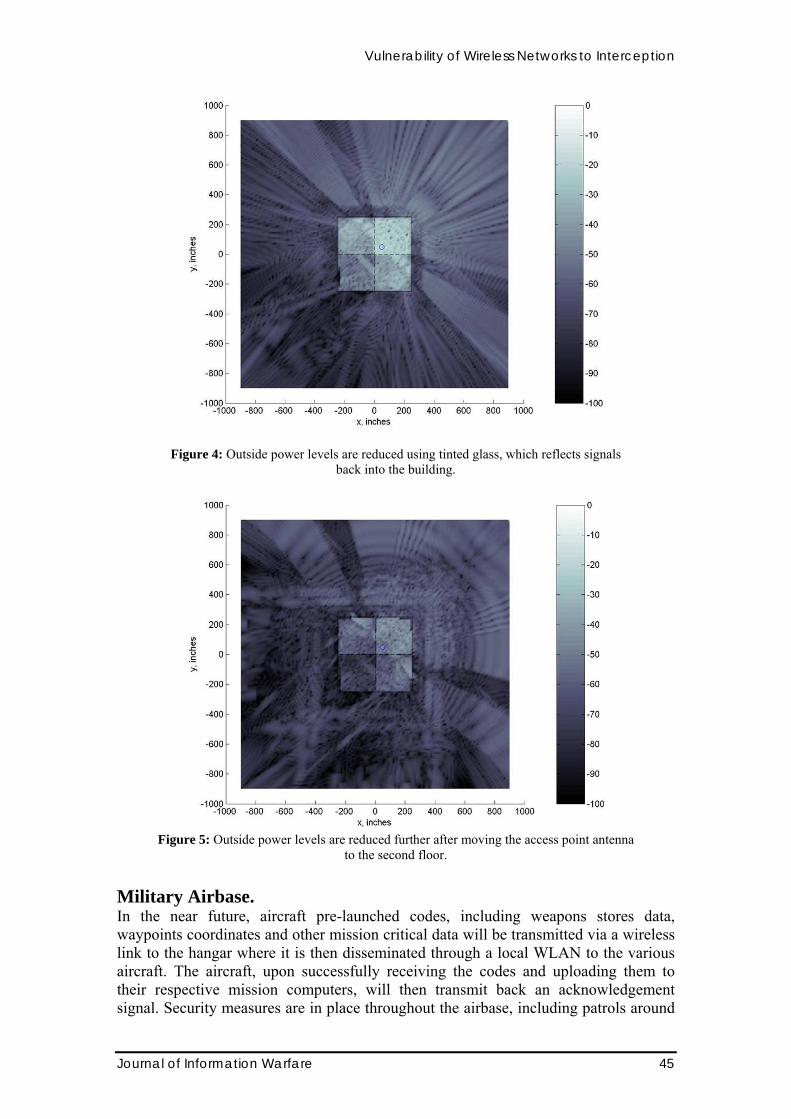
Figure 3 shows the signal distribution for a transmitter power of 100 milliwatts. The solid and dashed lines represent exterior and interior wall locations, respectively. The access point antenna is on the first floor, at x = y = 50 inches (denoted by the location of the “o” in the figure). Strong signals passing through the windows are evident. Although the strongest signals are confined to the interior of the building, significant levels are transmitted through the walls and windows. Roughly speaking, no interception would be possible in the dark areas using standard network receivers. Note that at the lowest data rate, interception is possible over most of the computational grid of 1800 inches (150 feet = 45.45 m) on a side. Sophisticated intercept receivers can be designed with much lower receiver sensitivities. For the data in Figure 4 the standard glass windows are replaced by tinted glass. There has been a significant reduction in the power outside of the building. A further reduction in the signal level outside can be achieved by moving the transmit antenna to the second floor, as evident in Figure 5.
Figure 3: Power levels for a building with metal composite walls and standard glass windows. Units
are decibels relative to a milliwatt (dBm).
Vulnerability of Wireless Networks to Interception
Journal of Information Warfare 45
Figure 4: Outside power levels are reduced using tinted glass, which reflects signals
back into the building.
Figure 5: Outside power levels are reduced further after moving the access point antenna
to the second floor.
Military Airbase. In the near future, aircraft pre-launched codes, including weapons stores data, waypoints coordinates and other mission critical data will be transmitted via a wireless link to the hangar where it is then disseminated through a local WLAN to the various aircraft. The aircraft, upon successfully receiving the codes and uploading them to their respective mission computers, will then transmit back an acknowledgement signal. Security measures are in place throughout the airbase, including patrols around

Vulnerability of Wireless Networks to Interception
46 Journal of Information Warfare
the perimeter, except perhaps a limited number of office buildings that are open to contractors and visitors. The objective of this scenario is to determine if there are possible security weaknesses that could arise. In particular, are there areas inside of the public buildings where sufficient signal strength exists so that interception is possible?
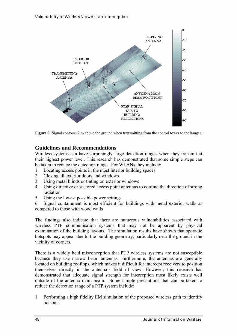
Figure 6 shows the airbase model with a point-to-point link between the control tower and aircraft hanger. The buildings are comprised of glass and concrete. PTP networks use high gain antennas with relatively narrow beam widths compared to those of WLAN access point antennas. Figure 7 shows the signal levels at two heights for a vertically polarized antenna with a 15-degree half power beam width (HPBW), when transmitting 30 dBm. At the higher observation level, the fine structure of the antenna sidelobes is evident. In the airbase model, the heights of the transmitting and receiving antennas are not the same. In order to point the main beam of the two antennas directly at each other, they have to be rotated. A downward pointing of the antenna results in more sidelobe peaks intercepting the ground plane. The peaks lead to localized areas of high signal strength, or so-called “hotspots.” Figure 8 shows the signal contours at a height of 2 meters above the ground when the antenna at the hanger is transmitting and pointed directly at the tower. Figure 9 shows the contours that result when the antenna at on the control tower is transmitting. In the second case, it was observed that there was a hotspot, as indicated in Figure 9, with a level near 30 dBm. This is due to the orientation of the cluster of the buildings, which were closer to the control tower than to the aircraft hangar. The junctions of two vertical building walls along with the ground serve as an effective “corner reflector” that can focus the signal at a limited number of nearby points. This presents a potential opportunity for covert entities to hack into the system. It is interesting to note that the hotspots caused by local features in the geometry (e.g., a corner reflector) are not reciprocal in the sense that they may be present when transmitting from control tower to the hangar, but not when transmitting from the hangar to the control tower.
Figure 6: Airbase model with a point-to-point link between a control tower and aircraft hanger.
Building edges are highlighted.

Vulnerability of Wireless Networks to Interception
Journal of Information Warfare 47
–5 dBm
–70 dBm
5 dBm
–70 dBm
GROUND z = 0
z
z = 0 m
z = 7 m
ANTENNAHEIGHTz = 16 m
Figure 7: The antenna radiation at observation points on the ground (z = 0) and at z = 7 m above the
ground. The antenna height is z = 16 m.
Figure 8: Signal contours 2 m above the ground when transmitting from the hanger to the control tower.
Vulnerability of Wireless Networks to Interception
48 Journal of Information Warfare
Figure 9: Signal contours 2 m above the ground when transmitting from the control tower to the hanger.
Guidelines and Recommendations Wireless systems can have surprisingly large detection ranges when they transmit at their highest power level. This research has demonstrated that some simple steps can be taken to reduce the detection range. For WLANs they include: 1. Locating access points in the most interior building spaces 2. Closing all exterior doors and windows 3. Using metal blinds or tinting on exterior windows 4. Using directive or sectored access point antennas to confine the direction of strong
radiation 5. Using the lowest possible power settings 6. Signal containment is most efficient for buildings with metal exterior walls as compared to those with wood walls
The findings also indicate that there are numerous vulnerabilities associated with wireless PTP communication systems that may not be apparent by physical examination of the building layouts. The simulation results have shown that sporadic hotspots may appear due to the building geometry, particularly near the ground in the vicinity of corners. There is a widely held misconception that PTP wireless systems are not susceptible because they use narrow beam antennas. Furthermore, the antennas are generally located on building rooftops, which makes it difficult for intercept receivers to position themselves directly in the antenna’s field of view. However, this research has demonstrated that adequate signal strength for interception most likely exists well outside of the antenna main beam. Some simple precautions that can be taken to reduce the detection range of a PTP system include: 1. Performing a high fidelity EM simulation of the proposed wireless path to identify
hotspots

Vulnerability of Wireless Networks to Interception
Journal of Information Warfare 49
2. Properly selecting the user’s receiver sensitivity so that the minimum power level can be transmitted (this technique is known as power management)
3. Stepping up physical security in the regions where the signal is strong enough for interception
4. Implementation of more advanced software encryption techniques 5. Incorporating low probability of intercept methods in the waveform design, e.g.,
frequency hopping (Couch 1995) Conclusions The fact that a WLAN is contained inside of a closed building, or PTP antennas are in a restricted area, may lead to a false sense of security. Many small businesses use these networks, yet their system administrators are not aware of the susceptibility of the systems to interception, or feel that they do not have the resources to tighten security. This research has identified several possible system weaknesses and suggested some simple, yet effective, methods of improving security. References Andersen, J. B., Rappaport, T. S. and Yoshida, S. (1995) Propagation measurements and models for wireless communications channels, IEEE Communications Magazine, 33, 1:42 − 49. Andersh, D. J., Lee, S. W., Ling, H. (1996) A High Frequency Electromagnetic Scattering Prediction Code Using Shooting and Bouncing Rays, IEEE Antennas and Propagation Magazine, 38, 3: 28-38. Balanis, C. A. (1997) Antenna Theory, Analysis and Design, second edition, Wiley, New York. Balanis, C. A. (1989) Advanced Engineering Electromagnetics, Wiley, New York. Boerner, G. L. (1995) The Brave new World of Wireless Technologies, Syllabus, October. Cheng, D. K. (1992) Field and Wave Electromagnetics, second edition, Addison Wesley, New York. Cisco (2004) on URL, http://www.cisco.com/en/US/products/hw/wireless/ps430/products_data_sheet09186a00800937a6.html, [date accessed: 10 February 2004]. Conjungi Networks (2003) Wireless Security Notes: A Brief Analysis of Risk, White Paper, Conjungi Networks, URL: http://portweb.flukenetworks.com, [date accessed: 2 March 2004]. Couch, L. W. (1995) Modern Communication Systems, Principles and Applications, Prentice Hall, Upper Saddle River, NJ. Deschamps, G. A. (1972) Ray Techniques in Electromagnetics, Proceedings of the IEEE, 60, 1022-2035.

Vulnerability of Wireless Networks to Interception
50 Journal of Information Warfare
ITworld (2003) Defensive Positions: Countering the growing threats to mobile and wireless security, webcast produced by ITworld, URL: http://security.itworld.com/webcasts/analyst_briefings/, [date accessed: 28 February 2004]. Keller, J. B. (1962) Geometrical Theory of Diffraction, Journal of the Optical Society of America, 52, 2: 116. Lim, Melvin Wee Pin, (2003) Vulnerability of Wireless Point-to-Point Systems to Interception, Masters thesis, Naval Postgraduate School, December. Loredo, S., Valle, L, and Torres, R. P. (2001) Accuracy Analysis of GO/UTD Radio-channel Modeling in Indoor Scenarios at 1.8 and 2.5 GHz, IEEE Antennas and Propagation Magazine, 43,5:37-51. Molkdar, D. (1991) Review on Radio Propagation into and Within Buildings, IEE Proceedings-H, 138,1:61-73. Pahlavan, K. (1995) Trends in Local Wireless Networks, IEEE Communications Magazine, 33, 3:88-95. Science Applications International Corporation (SAIC) (1998) Urbana Wireless Toolset, unpublished training notes; information available at URL: http://www.saic.com/products/software/urbana/ [date accessed: 10 March 2004]. Singhal, S., Probert, T. H., and Chase, M. E. (2001) The Seven Deadly Sins of Wireless LANS, on URL www.reefedge.com, [date accessed: 10 December]. Sumagasay, Paul P. (2002) Vulnerability of WLANs to Interception, Masters thesis, Naval Postgraduate School, September.