vrf, mpls and mpbgp - alcatron.net live 2015 melbourne/cisco live cont… · – mpls vpn over...
TRANSCRIPT


#clmel
VRF, MPLS and MPBGP Fundamentals
BRKCRT-2601
Andre Laurent, 3X CCIE/CCDE
© 2015 Cisco and/or its affi liates. All rights reserved.BRKCRT-2601 Cisco Public
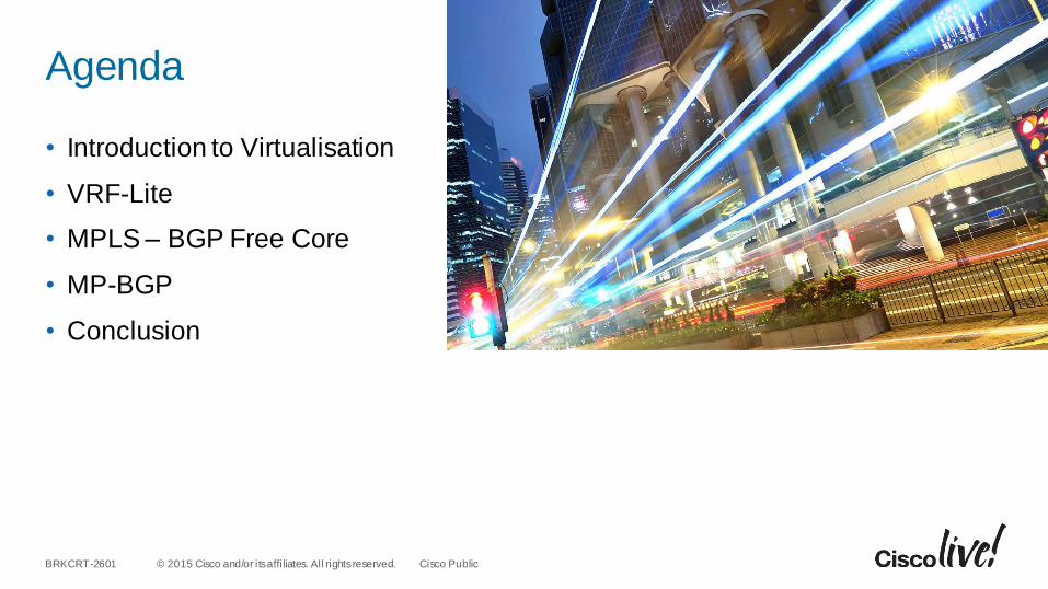
Agenda
• Introduction to Virtualisation
• VRF-Lite
• MPLS – BGP Free Core
• MP-BGP
• Conclusion

Introduction

© 2015 Cisco and/or its affi liates. All rights reserved.BRKCRT-2601 Cisco Public
MPLSThe Common Perception
• CE Routers owned by customer
• PE Routers owned by SP
• Customer “peers” to “PE” via IP
• Exchanges routing with SP via routing protocol (or static route)
• Customer relies on SP to advertise routes to reach other customer CEs
Provider
MPLS
VPNSite 2
Site3
Site1
IP Routing Peer
(BGP, Static, IGP)
PE PE
SP Demarcation
CE
CE
CE
Customer
Managed
Customer
Managed
* No Labels Are Exchanged with the SP

© 2015 Cisco and/or its affi liates. All rights reserved.BRKCRT-2601 Cisco Public
SiSi
Enterprise Network VirtualisationKey Building Blocks
Device Partitioning Virtualised Interconnect
“Virtualising” the Routing
and Forwarding of the DeviceExtending and Maintaining the
“Virtualised” Devices/Pools over Any Media
VRFVRF
Global

© 2015 Cisco and/or its affi liates. All rights reserved.BRKCRT-2601 Cisco Public
VRF VRFVRF
Global
VRF—Virtual Routing and ForwardingVLAN—Virtual LAN
Virtualise at Layer 3 forwarding
Associates to one or more Layer 3 interfaces on
router/switch
Each VRF has its own
Forwarding table (CEF)
Routing process (RIP, EIGRP, OSPF, BGP)
Interconnect options (VRF-Lite)?
802.1q, GRE, sub-interfaces, physical cables,
signalling
Virtualise at Layer 2 forwarding
Associates to one or more L2 interfaces on switch
Has its own MAC forwarding table and spanning-tree instance per VLAN
Interconnect options?
VLANs are extended via a physical cable or virtual
802.1q trunk
Device PartioningLayer 2 vs. Layer 3 Virtualisation
© 2015 Cisco and/or its affi liates. All rights reserved.BRKCRT-2601 Cisco Public
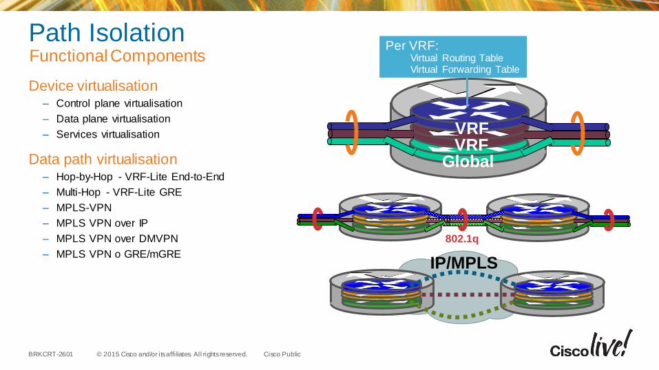
Path IsolationFunctional Components
Device virtualisation– Control plane virtualisation
– Data plane virtualisation
– Services virtualisation
Data path virtualisation– Hop-by-Hop - VRF-Lite End-to-End
– Multi-Hop - VRF-Lite GRE
– MPLS-VPN
– MPLS VPN over IP
– MPLS VPN over DMVPN
– MPLS VPN o GRE/mGRE
VRFVRF
Global
IP/MPLS
802.1q
Per VRF:Virtual Routing TableVirtual Forwarding Table

VRF-Lite

© 2015 Cisco and/or its affi liates. All rights reserved.BRKCRT-2601 Cisco Public
WAN/Campus
VRFVRFVRF
VRFVRFVRF
Defined router supports routing (RIB), forwarding (FIB), and interface per VRF
Leverages “Virtual” encapsulation for separation:
Ethernet/802.1Q, GRE, Frame Relay
The routing protocol is also “VRF aware”
RIP/v2, EIGRP, OSPF, BGP, static (per VFR)
Layer 3 VRF interfaces cannot belong to more than a single VRF
802.1q, GRE, DLCI
Per VRF:Virtual Routing TableVirtual Forwarding Table
What is VRF-Lite?Functional Components

© 2015 Cisco and/or its affi liates. All rights reserved.BRKCRT-2601 Cisco Public
VLAN 10
VLAN 20
IGPs
End to End segmentation, per VRF and per interface
Targets a small number of VRFs as requirement
Seen frequently in Access Distribution (vs. end to end)
No MP-BGP or control plane signalling is required and does not use labels
No LDP is required (i.e. MPLS)
Still leverages existing QoS model and supports IP multicast
Full range of platform support within the Cisco portfolio of switches and routers
VLAN 16
VLAN 26
VLAN 12
VLAN 22
VLAN 13
VLAN 23
VLAN 15
VLAN 25
VLAN 11
VLAN 21
VLAN 14
VLAN 24
VRF-Lite End-to-EndTarget Requirements
© 2015 Cisco and/or its affi liates. All rights reserved.BRKCRT-2601 Cisco Public
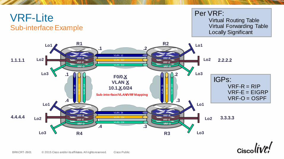
VRF-LiteSub-interface Example
Per VRF:Virtual Routing TableVirtual Forwarding TableLocally Significant
Sub-interface/VLAN/VRF Mapping
VRF-R
VRF-E
VRF-O
VRF-R
VRF-E
VRF-O
VLAN 12
VLAN 112
VLAN 212
VRF-R
VRF-E
VRF-O
VRF-R
VRF-E
VRF-O
VLAN 34
VLAN 134
VLAN 234
VLA
N 23
VLA
N 123
VLA
N 223
VLA
N 14
VLA
N 114
VLA
N 214
R1 R2
R4 R3
F0/0.X
VLAN X
10.1.X.0/24
1.1.1.1 2.2.2.2
3.3.3.34.4.4.4
Lo1
Lo2
Lo3
Lo1
Lo2
Lo3
Lo1
Lo2
Lo3
Lo1
Lo2
Lo3
.1
.1
.2
.2
.3
.3.4
.4
IGPs:VRF-R = RIPVRF-E = EIGRPVRF-O = OSPF
© 2015 Cisco and/or its affi liates. All rights reserved.BRKCRT-2601 Cisco Public
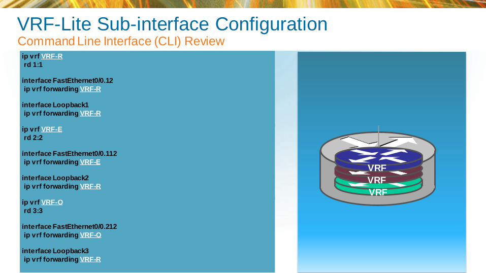
VRF-Lite Sub-interface ConfigurationCommand Line Interface (CLI) Review
ip vrf VRF-R
rd 1:1
interface FastEthernet0/0.12
ip vrf forwarding VRF-R
interface Loopback1
ip vrf forwarding VRF-R
ip vrf VRF-E
rd 2:2
interface FastEthernet0/0.112
ip vrf forwarding VRF-E
interface Loopback2
ip vrf forwarding VRF-R
ip vrf VRF-O
rd 3:3
interface FastEthernet0/0.212
ip vrf forwarding VRF-O
interface Loopback3
ip vrf forwarding VRF-R
VRF
VRF
VRF
© 2015 Cisco and/or its affi liates. All rights reserved.BRKCRT-2601 Cisco Public
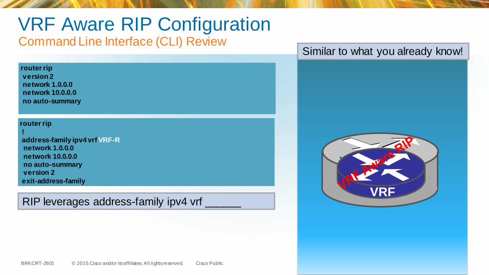
VRF Aware RIP ConfigurationCommand Line Interface (CLI) Review
router rip
version 2network 1.0.0.0network 10.0.0.0
no auto-summary
router rip
!address-family ipv4 vrf VRF-Rnetwork 1.0.0.0
network 10.0.0.0no auto-summaryversion 2
exit-address-family
VRF
Similar to what you already know!
RIP leverages address-family ipv4 vrf ______

© 2015 Cisco and/or its affi liates. All rights reserved.BRKCRT-2601 Cisco Public
VRF Aware EIGRP ConfigurationCommand Line Interface (CLI) Review
router eigrp 10
network 1.1.1.1 0.0.0.0network 10.1.112.0 0.0.0.255no auto-summary
router eigrp 10
auto-summary!address-family ipv4 vrf VRF-E
network 1.1.1.1 0.0.0.0network 10.1.112.0 0.0.0.255no auto-summary
autonomous-system 10exit-address-family
VRF
Similar to what you already know!
EIGRP leverages address-family ipv4 vrf ______
Set unique autonomous system number per VRF
© 2015 Cisco and/or its affi liates. All rights reserved.BRKCRT-2601 Cisco Public
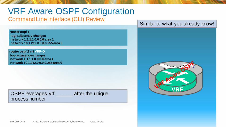
VRF Aware OSPF ConfigurationCommand Line Interface (CLI) Review
router ospf 1
log-adjacency-changesnetwork 1.1.1.1 0.0.0.0 area 1network 10.1.212.0 0.0.0.255 area 0
router ospf 2 vrf VRF-O
log-adjacency-changesnetwork 1.1.1.1 0.0.0.0 area 1network 10.1.212.0 0.0.0.255 area 0
VRF
Similar to what you already know!
OSPF leverages vrf ______ after the unique process number

Live Exploration
© 2015 Cisco and/or its affi liates. All rights reserved.BRKCRT-2601 Cisco Public
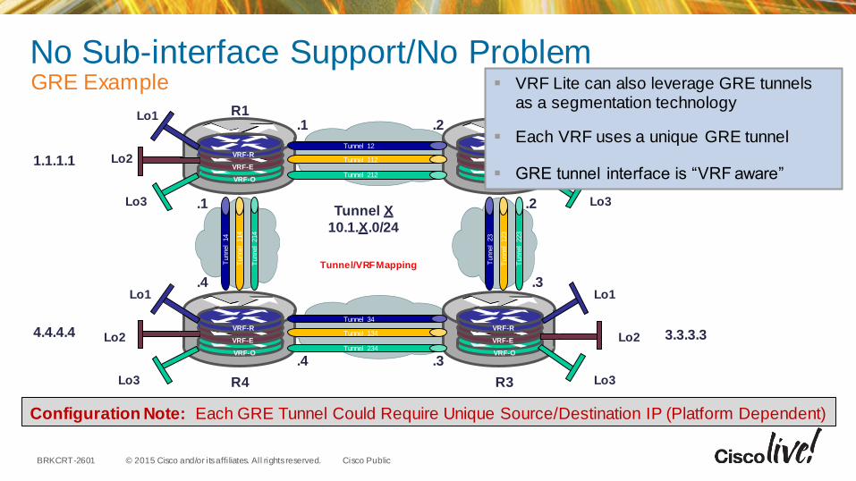
No Sub-interface Support/No ProblemGRE Example
Tunnel/VRF Mapping
VRF-R
VRF-E
VRF-O
VRF-R
VRF-E
VRF-O
Tunnel 12
Tunnel 112
Tunnel 212
VRF-R
VRF-E
VRF-O
VRF-R
VRF-E
VRF-O
Tunnel 34
Tunnel 134
Tunnel 234
Tunnel
23
Tunnel
123
Tunnel
223
Tunnel
14
Tunnel
114
Tunnel
214
R1 R2
R4 R3
Tunnel X
10.1.X.0/24
1.1.1.1
3.3.3.34.4.4.4
Lo1
Lo2
Lo3
Lo1
Lo2
Lo3
Lo1
Lo3
Lo1
Lo2
Lo3
.1
.1
.2
.2
.3
.3.4
.4
VRF Lite can also leverage GRE tunnels as a segmentation technology
Each VRF uses a unique GRE tunnel
GRE tunnel interface is “VRF aware”
Configuration Note: Each GRE Tunnel Could Require Unique Source/Destination IP (Platform Dependent)
© 2015 Cisco and/or its affi liates. All rights reserved.BRKCRT-2601 Cisco Public
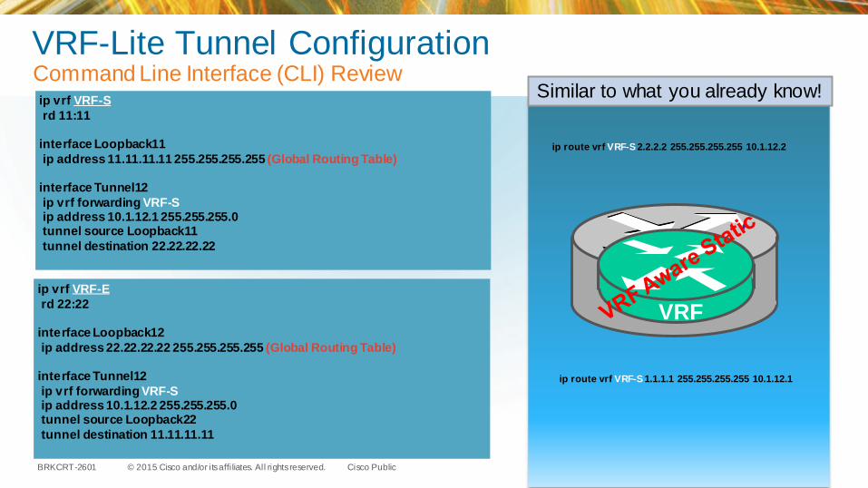
VRF-Lite Tunnel ConfigurationCommand Line Interface (CLI) Reviewip vrf VRF-S
rd 11:11
interface Loopback11
ip address 11.11.11.11 255.255.255.255 (Global Routing Table)
interface Tunnel12
ip vrf forwarding VRF-Sip address 10.1.12.1 255.255.255.0tunnel source Loopback11
tunnel destination 22.22.22.22
ip vrf VRF-E
rd 22:22
interface Loopback12
ip address 22.22.22.22 255.255.255.255 (Global Routing Table)
interface Tunnel12
ip vrf forwarding VRF-Sip address 10.1.12.2 255.255.255.0tunnel source Loopback22
tunnel destination 11.11.11.11
Similar to what you already know!
VRF
ip route vrf VRF-S 2.2.2.2 255.255.255.255 10.1.12.2
ip route vrf VRF-S 1.1.1.1 255.255.255.255 10.1.12.1

© 2015 Cisco and/or its affi liates. All rights reserved.BRKCRT-2601 Cisco Public
Layer 2 Serial Link/No ProblemBack-to-Back Frame Relay Example
FR VC/VRF Mapping
VRF-R
VRF-E
VRF-O
VRF-R
VRF-E
VRF-O
Serial0/0.12
Serial0/0.112
Serial0/0.212
VRF-R
VRF-E
VRF-O
VRF-R
VRF-E
VRF-O
Serial0/0.34
Serial0/0.134
Serial0/0.234
Seri
al0
/1.2
3
Seri
al0
/1.1
23
Seri
al0
/1.2
23
Seri
al0
/1.1
4
Seri
al0
/1.1
14
Seri
al0
/1.2
14
R1 R2
R4 R3
Serial0/0.X
Serial0/1.X
10.1.X.0/24
1.1.1.1
3.3.3.34.4.4.4
Lo1
Lo2
Lo3
Lo1
Lo2
Lo3
Lo1
Lo3
Lo1
Lo2
Lo3
.1
.1
.2
.2
.3
.3.4
.4
VRF Lite can also leverage Frame Relay Sub-interfaces as a segmentation
technology
Each VRF uses a unique Frame-Relay
sub-interface and DLCI
Frame Relay sub-interface is “VRF aware”
Configuration Note: Leveraging Back-to-Back Frame-Relay Configuration
© 2015 Cisco and/or its affi liates. All rights reserved.BRKCRT-2601 Cisco Public
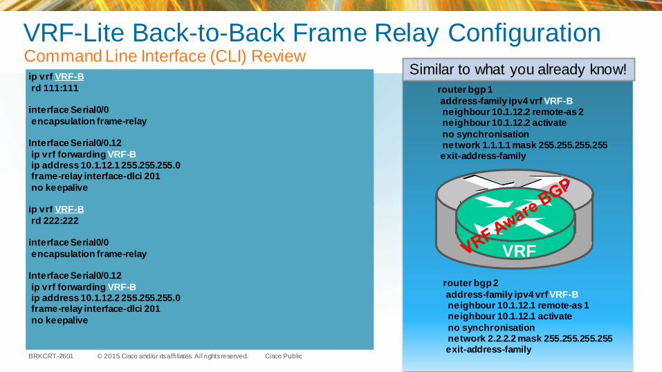
ip vrf VRF-B
rd 222:222
interface Serial0/0
encapsulation frame-relay
Interface Serial0/0.12
ip vrf forwarding VRF-Bip address 10.1.12.2 255.255.255.0frame-relay interface-dlci 201
no keepalive
VRF-Lite Back-to-Back Frame Relay ConfigurationCommand Line Interface (CLI) Reviewip vrf VRF-B
rd 111:111
interface Serial0/0
encapsulation frame-relay
Interface Serial0/0.12
ip vrf forwarding VRF-Bip address 10.1.12.1 255.255.255.0frame-relay interface-dlci 201
no keepalive
Similar to what you already know!
VRF
router bgp 1
address-family ipv4 vrf VRF-Bneighbour 10.1.12.2 remote-as 2neighbour 10.1.12.2 activate
no synchronisationnetwork 1.1.1.1 mask 255.255.255.255exit-address-family
router bgp 2
address-family ipv4 vrf VRF-Bneighbour 10.1.12.1 remote-as 1neighbour 10.1.12.1 activate
no synchronisationnetwork 2.2.2.2 mask 255.255.255.255exit-address-family

Live Exploration
© 2015 Cisco and/or its affi liates. All rights reserved.BRKCRT-2601 Cisco Public
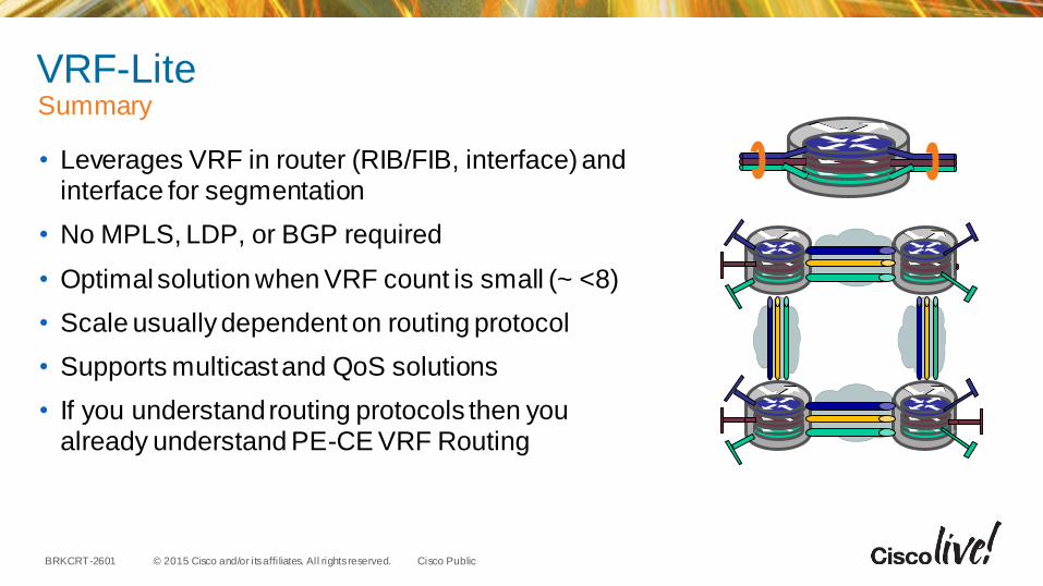
VRF-Lite Summary
• Leverages VRF in router (RIB/FIB, interface) and interface for segmentation
• No MPLS, LDP, or BGP required
• Optimal solution when VRF count is small (~ <8)
• Scale usually dependent on routing protocol
• Supports multicast and QoS solutions
• If you understand routing protocols then you already understand PE-CE VRF Routing

MPLS – BGP Free Core
© 2015 Cisco and/or its affi liates. All rights reserved.BRKCRT-2601 Cisco Public
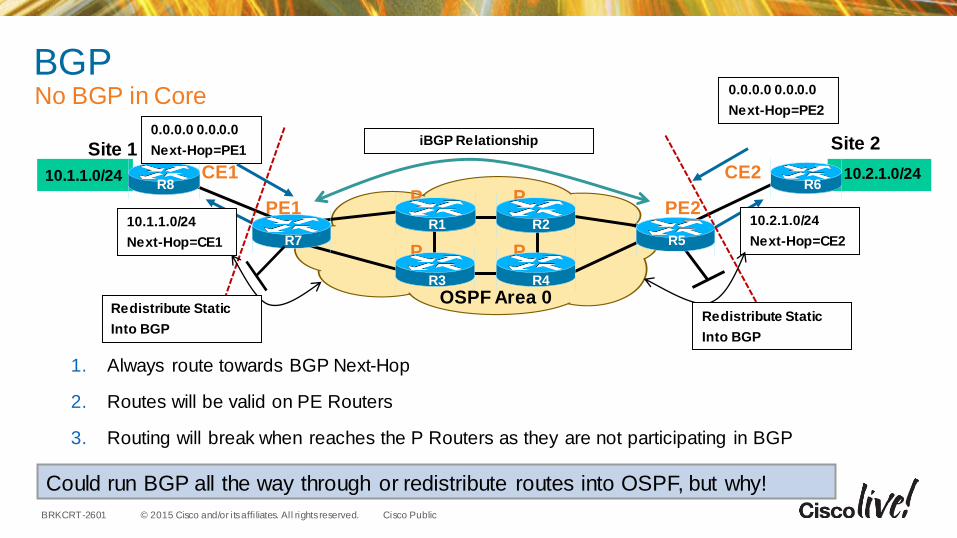
BGPNo BGP in Core
1. Always route towards BGP Next-Hop
2. Routes will be valid on PE Routers
3. Routing will break when reaches the P Routers as they are not participating in BGP
10.1.1.0/24
Next-Hop=CE1
iBGP Relationship
10.1.1.0/24
PE1 PE2P
P P
P
CE2CE1
OSPF Area 0
Site 1 Site 2
10.2.1.0/24
10.2.1.0/24
Next-Hop=CE2
Redistribute Static
Into BGP
Redistribute Static
Into BGP
Could run BGP all the way through or redistribute routes into OSPF, but why!
R1 R2
R3 R4
R5
R6
R7
R8
0.0.0.0 0.0.0.0
Next-Hop=PE2
0.0.0.0 0.0.0.0
Next-Hop=PE1
© 2015 Cisco and/or its affi liates. All rights reserved.BRKCRT-2601 Cisco Public
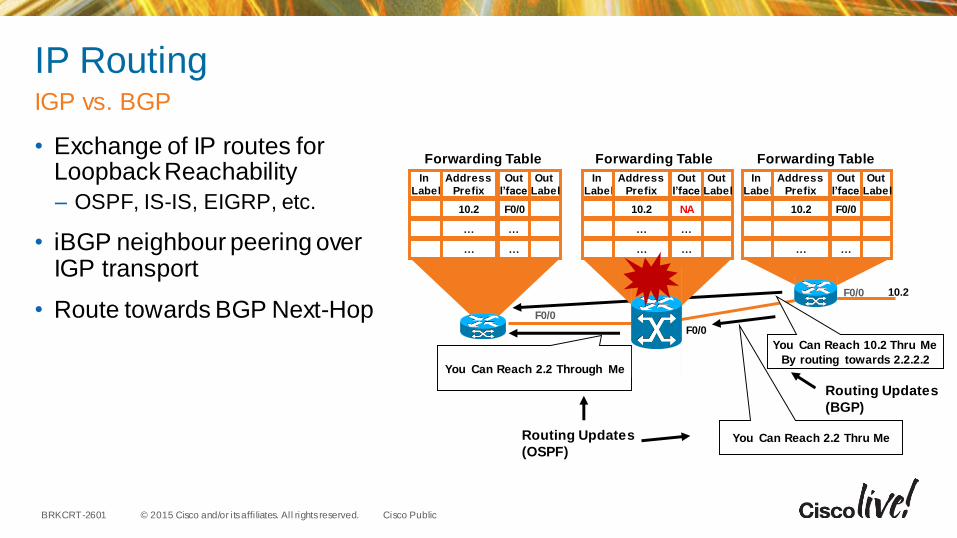
IP Routing
• Exchange of IP routes for Loopback Reachability
– OSPF, IS-IS, EIGRP, etc.
• iBGP neighbour peering over IGP transport
• Route towards BGP Next-Hop
IGP vs. BGP
10.2
F0/0
In
Label
Address
Prefix
…
Out
I’face
10.2 F0/0
… …
…
Out
Label
In
Label
Address
Prefix
…
Out
I’face
10.2 NA
… …
…
Out
Label
In
Label
Address
Prefix
10.2
…
Out
I’face
F0/0
…
Out
Label
F0/0
You Can Reach 2.2 Through Me
Routing Updates
(OSPF)
You Can Reach 10.2 Thru Me
By routing towards 2.2.2.2
Forwarding Table Forwarding Table Forwarding Table
F0/0
You Can Reach 2.2 Thru Me
Routing Updates
(BGP)
© 2015 Cisco and/or its affi liates. All rights reserved.BRKCRT-2601 Cisco Public
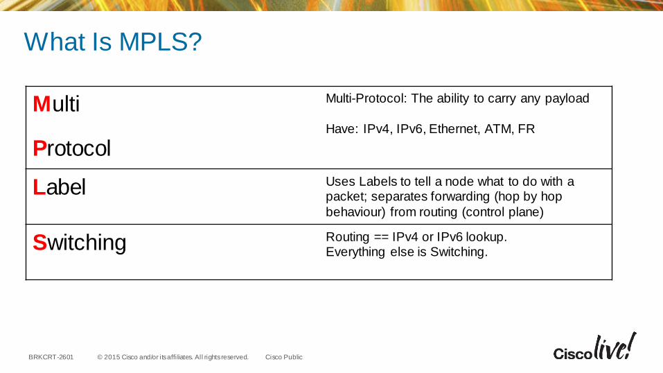
What Is MPLS?
Multi Multi-Protocol: The ability to carry any payload
Have: IPv4, IPv6, Ethernet, ATM, FR
Protocol
Label Uses Labels to tell a node what to do with a packet; separates forwarding (hop by hop
behaviour) from routing (control plane)
Switching Routing == IPv4 or IPv6 lookup.Everything else is Switching.

© 2015 Cisco and/or its affi liates. All rights reserved.BRKCRT-2601 Cisco Public
MPLS Path (LSP) Setup with LDP
• Local label mapping are sent to connected nodes
• Receiving nodes update forwarding table– Out label
• LDP label advertisement happens in parallel (downstream unsolicited)
Assignment of Remote Labels
1
10.2
F0/0F0/0
Use Label 30 for 2.2
Use Label 20 for 2.2
Label Distribution
Protocol (LDP)(Downstream
Allocation)
In
Label
Address
Prefix
2.2
…
…
Out
I’face
F0/0
…
…
Out
Label
In
Label
Address
Prefix
2.2
…
…
Out
I’face
F0/0
…
…
Out
Label
In
Label
Address
Prefix
10.2
…
Out
I’face
F0/0
…
Out
Label
20
…
-
-
…
30
…
20
…
…
-
…
30
…
Forwarding Table Forwarding Table Forwarding Table
F0/0
……
You Can Reach 10.2 Thru Me
By routing towards 2.2.2.2
© 2015 Cisco and/or its affi liates. All rights reserved.BRKCRT-2601 Cisco Public
You Can Reach 10.2 Thru Me
By routing towards 2.2.2.2
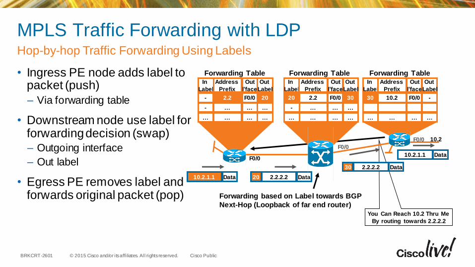
MPLS Traffic Forwarding with LDP
• Ingress PE node adds label to packet (push)
– Via forwarding table
• Downstream node use label for forwarding decision (swap)– Outgoing interface
– Out label
• Egress PE removes label and forwards original packet (pop)
Hop-by-hop Traffic Forwarding Using Labels
F0/0
10.2.1.1 Data 2.2.2.2 Data20
2.2.2.2 Data30
Forwarding based on Label towards BGP
Next-Hop (Loopback of far end router)
10.2.1.1 Data
10.2F0/0
In
Label
Address
Prefix
2.2
…
…
Out
I’face
F0/0
…
…
Out
Label
In
Label
Address
Prefix
2.2
…
…
Out
I’face
F0/0
…
…
Out
Label
In
Label
Address
Prefix
10.2
…
Out
I’face
F0/0
…
Out
Label
20
…
…
-
-
…
30
…
…
20
-
…
-
…
30
…
Forwarding Table Forwarding Table Forwarding Table
F0/0

© 2015 Cisco and/or its affi liates. All rights reserved.BRKCRT-2601 Cisco Public
BGPMPLS in Core
1. Always route towards BGP Next-Hop
2. Routes will be valid on PE Routers
3. Will label switch towards BGP Next-Hop with MPLS enabled
10.1.1.0/24
Next-Hop=CE1
iBGP Relationship
10.1.1.0/24
PE1 PE2P
P P
P
CE2CE1
OSPF Area 0
Site 1 Site 2
10.2.1.0/24
10.2.1.0/24
Next-Hop=CE2
0.0.0.0 0.0.0.0
Next-Hop=PE20.0.0.0 0.0.0.0
Next-Hop=PE1
End-to-End BGP and redistribution of routes into OSPF not necessary!
R1 R2
R3 R4
R5
R6
R7
R8

Live Exploration

MP-BGP

© 2015 Cisco and/or its affi liates. All rights reserved.BRKCRT-2601 Cisco Public
MPLS VPN Technology - RefresherMPLS VPN Connection Model
PE Routers
• MPLS Edge routers
• MPLS forwarding to P routers
• IGP/BGP – IP to CE routers
• Distributes VPN information through MP-BGP to other PE routers with VPN-IPv4 addresses, extended community, VPN labels
P Routers
• P routers are in the core of the MPLS cloud
• P routers do not need to run BGP
• Do not have knowledge of VPNs
• Switches packets based on labels (push/pop) not IP
PE
VPN Backbone IGP
MP-iBGP – VPNv4 Label Exchange
PEP P
P P
VRF Blue
VRF Green
EIGRP, OSPF, IS-IS, RIPv2, BGP, Static
CE
CE
VPN 1
VPN 2
CE Routers
VRF Associates to one or more interfaces on PE
Has its own routing table and forwarding table (CEF)
VRF has its own instance for the routing protocol
(static, RIP, BGP, EIGRP, OSPF)
Global Address Space
© 2015 Cisco and/or its affi liates. All rights reserved.BRKCRT-2601 Cisco Public
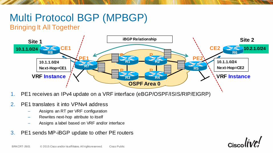
Multi Protocol BGP (MPBGP)Bringing It All Together
1. PE1 receives an IPv4 update on a VRF interface (eBGP/OSPF/ISIS/RIP/EIGRP)
2. PE1 translates it into VPNv4 address
– Assigns an RT per VRF configuration
– Rewrites next-hop attribute to itself
– Assigns a label based on VRF and/or interface
3. PE1 sends MP-iBGP update to other PE routers
10.1.1.0/24
Next-Hop=CE1
iBGP Relationship
10.1.1.0/24
PE1 PE2P
P P
P
CE2CE1
OSPF Area 0
Site 1 Site 2
10.2.1.0/24
10.1.1.0/24
Next-Hop=CE2
VRF InstanceVRF Instance
R1 R2
R3 R4
R5
R6
R7
R8
© 2015 Cisco and/or its affi liates. All rights reserved.BRKCRT-2601 Cisco Public
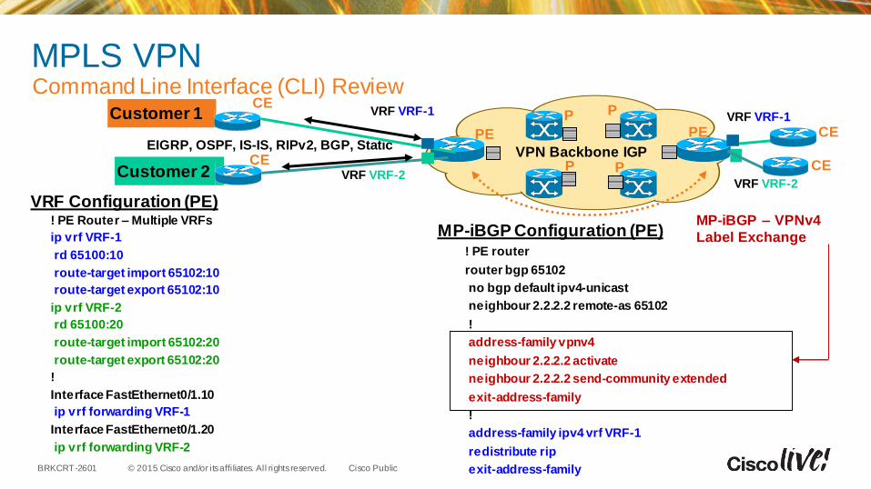
! PE router
router bgp 65102
no bgp default ipv4-unicast
neighbour 2.2.2.2 remote-as 65102
!
address-family vpnv4
neighbour 2.2.2.2 activate
neighbour 2.2.2.2 send-community extended
exit-address-family
!
address-family ipv4 vrf VRF-1
redistribute rip
exit-address-family
PE
VPN Backbone IGP
MP-iBGP – VPNv4
Label Exchange
PEP P
P P
MPLS VPNCommand Line Interface (CLI) Review
VRF VRF-1
VRF VRF-2
EIGRP, OSPF, IS-IS, RIPv2, BGP, Static
CE
CE
Customer 1
Customer 2
MP-iBGP Configuration (PE)
VRF VRF-1
VRF VRF-2
CE
CE
! PE Router – Multiple VRFs
ip vrf VRF-1
rd 65100:10
route-target import 65102:10
route-target export 65102:10
ip vrf VRF-2
rd 65100:20
route-target import 65102:20
route-target export 65102:20
!
Interface FastEthernet0/1.10
ip vrf forwarding VRF-1
Interface FastEthernet0/1.20
ip vrf forwarding VRF-2
VRF Configuration (PE)

Live Exploration

© 2015 Cisco and/or its affi liates. All rights reserved.BRKCRT-2601 Cisco Public
Closing Tips
• Separate the building blocks of “MPLS” to foster an improved understanding
• Don’t over complicate things
• PE-CE VRF based routing is not much different than regular routing
• MPLS LDP Configuration is pretty simple
• MPBGP and traditional IPv4 BGP configuration is nearly the same
• If routes are not present on CE routers check route-target import/export and redistribution between IPv4 VRF address-families under IGP and BGP
• If routes are present but you are having problems with reachability, check MPLS configuration
• Remember that on PE devices you are living in a VRF world
Personal Insights

Q & A
© 2015 Cisco and/or its affi liates. All rights reserved.BRKCRT-2601 Cisco Public
Give us your feedback and receive a
Cisco Live 2015 T-Shirt!
Complete your Overall Event Survey and 5 Session
Evaluations.
• Directly from your mobile device on the Cisco Live
Mobile App
• By visiting the Cisco Live Mobile Site
http://showcase.genie-connect.com/clmelbourne2015
• Visit any Cisco Live Internet Station located
throughout the venue
T-Shirts can be collected in the World of Solutions
on Friday 20 March 12:00pm - 2:00pm
Complete Your Online Session Evaluation
Learn online with Cisco Live! Visit us online after the conference for full
access to session videos and
presentations. www.CiscoLiveAPAC.com

Thank you.