volvo xc90 pcv system replacement - - volvo · pdf file · 2012-01-27microsoft word...
TRANSCRIPT
VOLVO XC90 PCV SYSTEM REPLACEMENT 2004 2.5T ENGINE NUMBER B5254T2
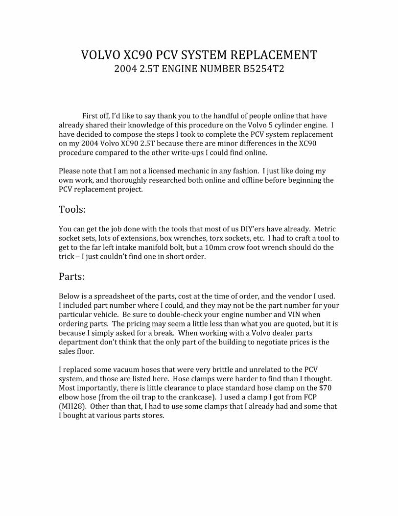
First off, I’d like to say thank you to the handful of people online that have already shared their knowledge of this procedure on the Volvo 5 cylinder engine. I have decided to compose the steps I took to complete the PCV system replacement on my 2004 Volvo XC90 2.5T because there are minor differences in the XC90 procedure compared to the other write-‐ups I could find online. Please note that I am not a licensed mechanic in any fashion. I just like doing my own work, and thoroughly researched both online and offline before beginning the PCV replacement project. Tools: You can get the job done with the tools that most of us DIY’ers have already. Metric socket sets, lots of extensions, box wrenches, torx sockets, etc. I had to craft a tool to get to the far left intake manifold bolt, but a 10mm crow foot wrench should do the trick – I just couldn’t find one in short order. Parts: Below is a spreadsheet of the parts, cost at the time of order, and the vendor I used. I included part number where I could, and they may not be the part number for your particular vehicle. Be sure to double-‐check your engine number and VIN when ordering parts. The pricing may seem a little less than what you are quoted, but it is because I simply asked for a break. When working with a Volvo dealer parts department don’t think that the only part of the building to negotiate prices is the sales floor. I replaced some vacuum hoses that were very brittle and unrelated to the PCV system, and those are listed here. Hose clamps were harder to find than I thought. Most importantly, there is little clearance to place standard hose clamp on the $70 elbow hose (from the oil trap to the crankcase). I used a clamp I got from FCP (MH28). Other than that, I had to use some clamps that I already had and some that I bought at various parts stores.
Part
Number Quantity Description Vendor Cost 11994 4 Copper Gasket (12) fcpeuro $1.00
30650578 1 Tube Assembly (10) Volvo $169.20 8692211 1 oil trap (1) fcpeuro $35.95
30677388 1 hose (oil trap to crankcase) (2) fcpeuro $68.95
8692217 1 hose (oil trap to head) (8) fcpeuro $25.95
8653339 1 hose (lower oil trap gromet) (6) fcpeuro $5.96
8653883 1 hollow screw (16) Volvo $21.70 9458534 1 Manifold Gasket fcpeuro $13.18 8636753 1 Throttle Body Gasket Volvo $5.43
8636573 1 Thermostat Housing Gasket Volvo $5.98
2' 5/16 ID Vaccum hose AutoZone $2.38 4' 3/8 ID Vaccum hose O'Reilly $5.96
1 40-60mm clamp 7mm wide fcpeuro $1.00
6 3/4" Hose Clamps AutoZone $7.14 9434699 1 Gallon Antifreeze Volvo $24.63
$394.41
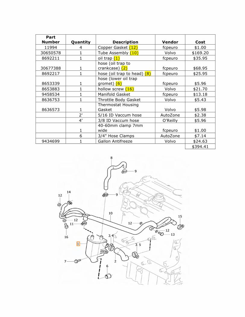
Getting Started The first step is to de-‐pressurize the fuel system. To do this, start the car then remove the fuel pump. The engine will run for about 20 seconds and then quit. Crank the engine for another 3-‐5 seconds, and then replace the fuse. Disconnect the battery at the negative terminal. It is best practice to wait for at least 10 minutes after turning the ignition off before disconnecting the battery. The reason is so that all of the information can store properly on the ECU. After the battery is disconnected you are ready to start disassembly. Remove the splash shield under the car. Remove the charge air pipe that runs over the engine. Remove the plastic injector cover, timing belt cover, and spark plug coil covers.
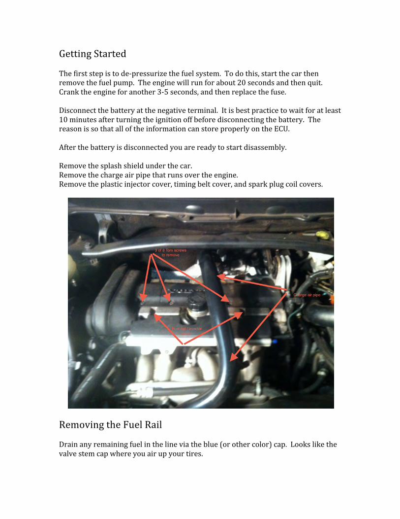
Removing the Fuel Rail Drain any remaining fuel in the line via the blue (or other color) cap. Looks like the valve stem cap where you air up your tires.
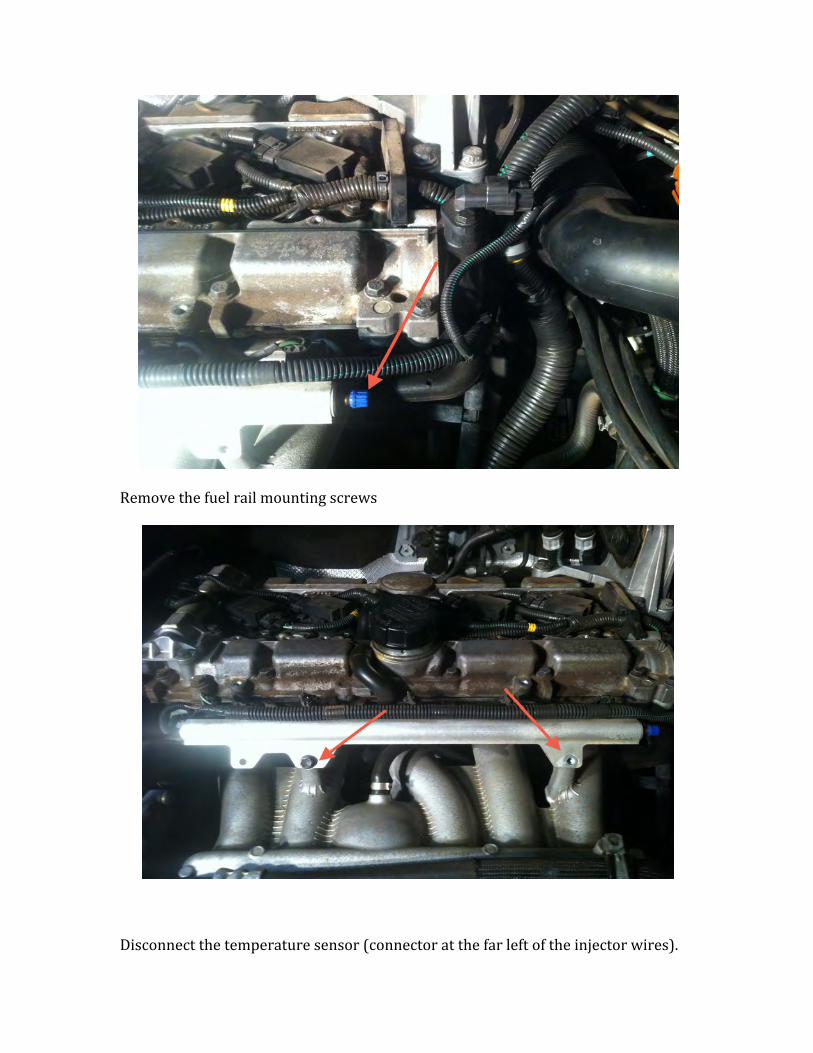
Remove the fuel rail mounting screws
Disconnect the temperature sensor (connector at the far left of the injector wires).
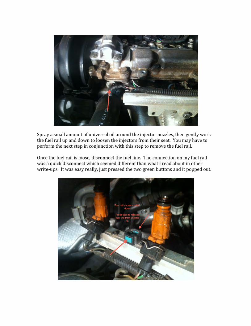
Spray a small amount of universal oil around the injector nozzles, then gently work the fuel rail up and down to loosen the injectors from their seat. You may have to perform the next step in conjunction with this step to remove the fuel rail. Once the fuel rail is loose, disconnect the fuel line. The connection on my fuel rail was a quick disconnect which seemed different than what I read about in other write-‐ups. It was easy really, just pressed the two green buttons and it popped out.
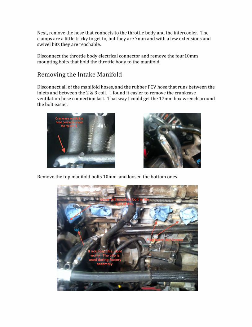
Next, remove the hose that connects to the throttle body and the intercooler. The clamps are a little tricky to get to, but they are 7mm and with a few extensions and swivel bits they are reachable. Disconnect the throttle body electrical connector and remove the four10mm mounting bolts that hold the throttle body to the manifold. Removing the Intake Manifold Disconnect all of the manifold hoses, and the rubber PCV hose that runs between the inlets and between the 2 & 3 coil. I found it easier to remove the crankcase ventilation hose connection last. That way I could get the 17mm box wrench around the bolt easier.
Remove the top manifold bolts 10mm. and loosen the bottom ones.
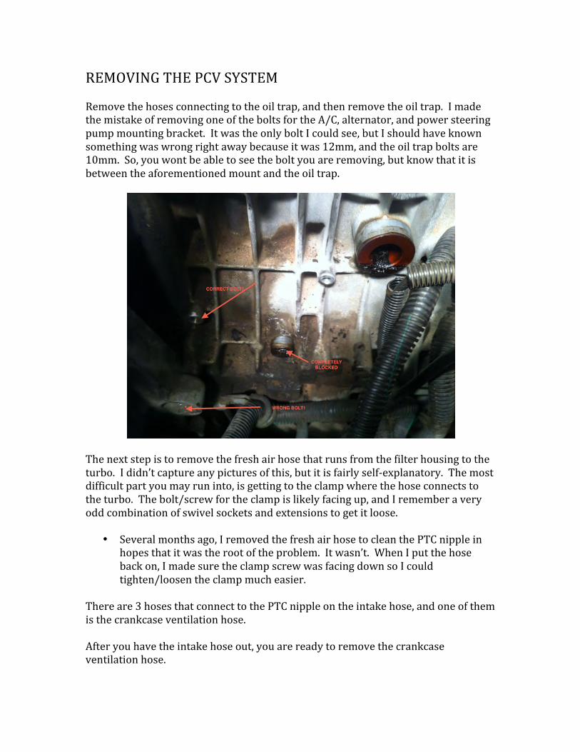
REMOVING THE PCV SYSTEM Remove the hoses connecting to the oil trap, and then remove the oil trap. I made the mistake of removing one of the bolts for the A/C, alternator, and power steering pump mounting bracket. It was the only bolt I could see, but I should have known something was wrong right away because it was 12mm, and the oil trap bolts are 10mm. So, you wont be able to see the bolt you are removing, but know that it is between the aforementioned mount and the oil trap.
The next step is to remove the fresh air hose that runs from the filter housing to the turbo. I didn’t capture any pictures of this, but it is fairly self-‐explanatory. The most difficult part you may run into, is getting to the clamp where the hose connects to the turbo. The bolt/screw for the clamp is likely facing up, and I remember a very odd combination of swivel sockets and extensions to get it loose.
• Several months ago, I removed the fresh air hose to clean the PTC nipple in hopes that it was the root of the problem. It wasn’t. When I put the hose back on, I made sure the clamp screw was facing down so I could tighten/loosen the clamp much easier.
There are 3 hoses that connect to the PTC nipple on the intake hose, and one of them is the crankcase ventilation hose. After you have the intake hose out, you are ready to remove the crankcase ventilation hose.
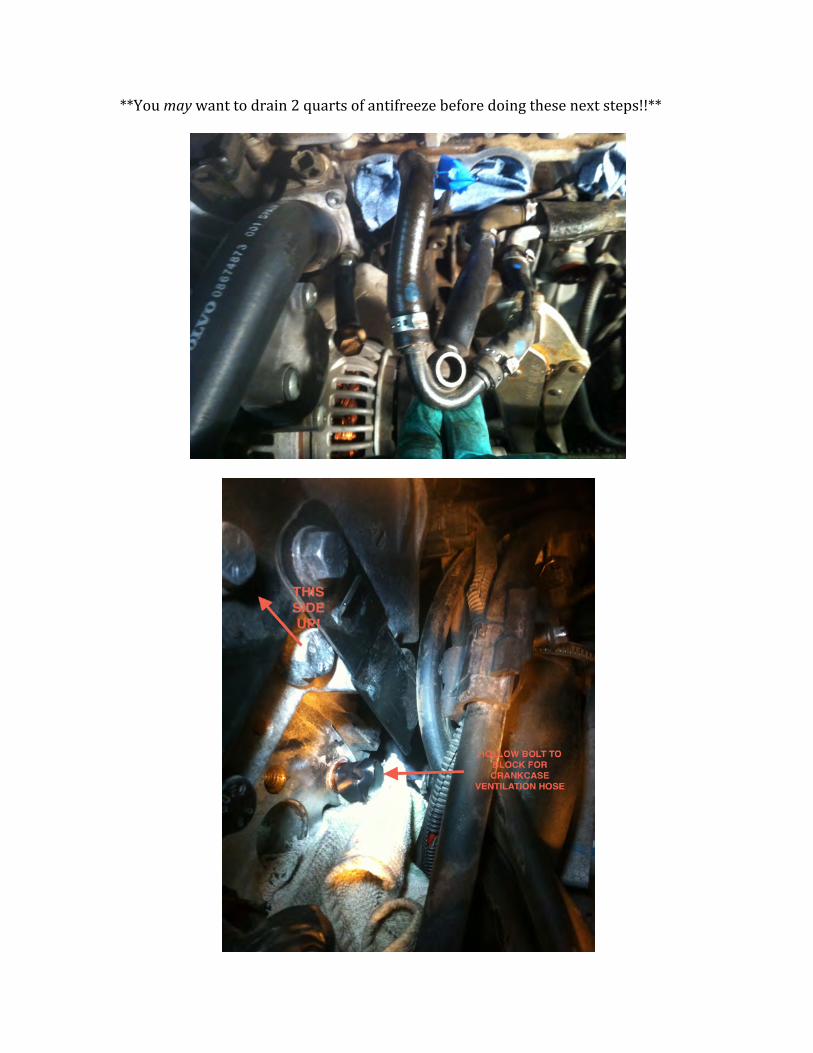
**You may want to drain 2 quarts of antifreeze before doing these next steps!!**
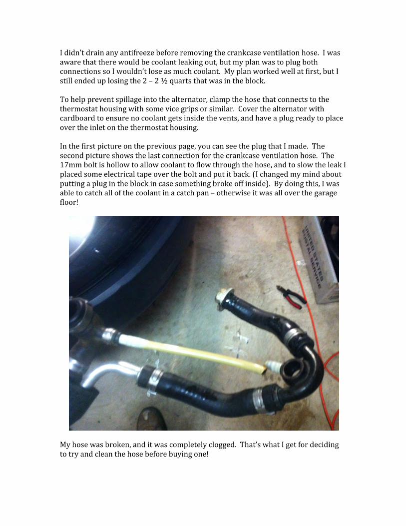
I didn’t drain any antifreeze before removing the crankcase ventilation hose. I was aware that there would be coolant leaking out, but my plan was to plug both connections so I wouldn’t lose as much coolant. My plan worked well at first, but I still ended up losing the 2 – 2 ½ quarts that was in the block. To help prevent spillage into the alternator, clamp the hose that connects to the thermostat housing with some vice grips or similar. Cover the alternator with cardboard to ensure no coolant gets inside the vents, and have a plug ready to place over the inlet on the thermostat housing. In the first picture on the previous page, you can see the plug that I made. The second picture shows the last connection for the crankcase ventilation hose. The 17mm bolt is hollow to allow coolant to flow through the hose, and to slow the leak I placed some electrical tape over the bolt and put it back. (I changed my mind about putting a plug in the block in case something broke off inside). By doing this, I was able to catch all of the coolant in a catch pan – otherwise it was all over the garage floor!
My hose was broken, and it was completely clogged. That’s what I get for deciding to try and clean the hose before buying one!
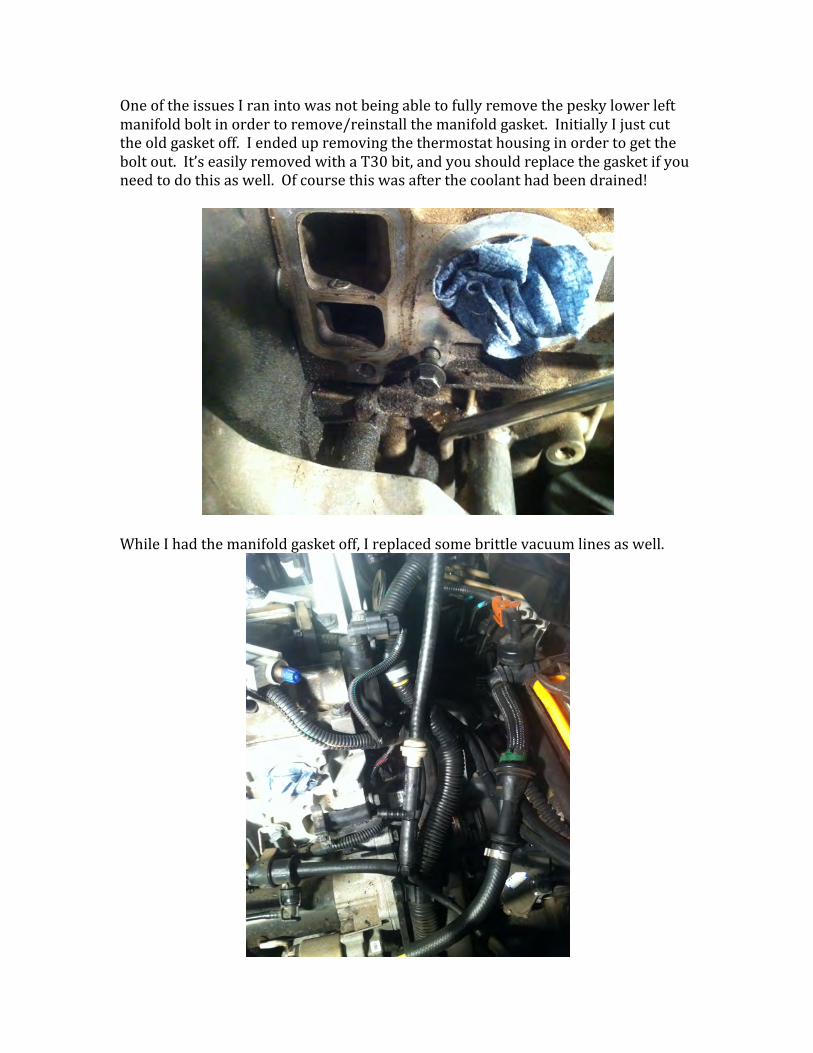
One of the issues I ran into was not being able to fully remove the pesky lower left manifold bolt in order to remove/reinstall the manifold gasket. Initially I just cut the old gasket off. I ended up removing the thermostat housing in order to get the bolt out. It’s easily removed with a T30 bit, and you should replace the gasket if you need to do this as well. Of course this was after the coolant had been drained!
While I had the manifold gasket off, I replaced some brittle vacuum lines as well.
Installation is the reverse of this procedure. If you had to remove the thermostat housing, be sure to place the manifold gasket and the lower left bolt prior to re-‐installing. Do a double and triple check to make sure everything that will be covered by the intake manifold is connected and routed properly. Take before and after pictures if it will help you remember.
Additional Information If your ports are blocked as mine were, clean out the sludge being careful not to push any back into the engine block. I used a shop vac, drill bit, and a paint can opener as suggested in other write-‐ups. When re-‐installing everything, be sure to torque the bolts properly. Below are the torque specs I could find for the important parts. I found a handy calculator online to convert from Newton meters to inch pounds, etc. www.unitconversion.org *** Be sure to use new copper gaskets (4 total) on the crankcase ventilation hose*** When reconnecting the battery, Volvo recommends the key being in position II in case an airbag module activates when the power is connected. After reconnecting the battery you must press the unlock button on your remote to initiate the upper electronic module. I was able to get the proper clamps from FCP euro, and any that I missed I picked up from the Volvo dealership. Don’t waste your time going to Auto Zone or O’Reillys. The clamps they sell are too wide for some of the hoses. Additionally, the clamps Volvo has will likely be 7mm – not SAE; no sense in getting out more tools than necessary. Applicable Torque Specs Intake manifold 19Nm Oil trap 15 Nm Knock sensor (if removed) 20 Nm Hollow pipe screw to block (c.c.v. hose) 26 Nm These are the only tightening torques I used. Your local Volvo dealership may provide you with any additional information you might need/want. In all, the job took me around 8 hours. I’ve seen others say that they were able to do it in around 6 hours. I spent a lot of time cleaning oil out of the air hoses and sludge out of the ports on the engine block. If three or four bolts were more accessible, this would be a pretty easy job. Good Luck!