voices of experience | advanced distribution management ... of... · insights into advanced...
TRANSCRIPT
Insights into Advanced Distribution Management Systems
VOICES of Experience
February, 2015
Voices of Experience | Advanced Distribution Management Systems_brochure.indd 1 2/11/15 12:52 PM

Prepared for the U.S. Department of Energy by the National Renewable
Energy Laboratory under contract No. DE-AC36-08G028308, Subtask
SG10.1011 in conjunction with Energetics Incorporated under contract
No. GS-10F-0103J, Subtask J3806.0002.
Voices of Experience | Advanced Distribution Management Systems_brochure.indd 2 2/11/15 12:52 PM
INSIGHTS INTO ADVANCED DISTRIBUTION MANAGEMENT SYSTEMS | DOE 3
Voices of Experience | Advanced Distribution Management SystemsWhen people think of the electric power grid, they tend to picture the massive high-voltage transmission lines and tall
towers that march across the countryside. But the smaller medium- and low-voltage lines of the electric distribution
system cover the most distance and deliver power to almost every home and business in the country.
Considering that this is an era in which smart phones and Google Maps are ubiquitous, it may come as a surprise that
utilities have very little visibility into their distribution systems. Most systems still rely on breakers to disconnect the lines
in the event of a fault, customers to call in to report an outage, and line crews to fi nd the e� ected circuit and restore
power. However, this may be changing.
Today, a number of utilities are implementing advanced distribution management systems (ADMS), a software platform
that integrates numerous utility systems and provides automated outage restoration and optimization of distribution
grid performance. ADMS functions can include automated fault location, isolation, and service restoration (FLISR);
conservation voltage reduction; peak demand management; and volt/volt-ampere reactive (volt/VAR) optimization. In
e� ect, an ADMS transitions utilities from paperwork, manual processes, and siloed software systems to systems with
real-time and near-real-time data, automated processes, and integrated systems.
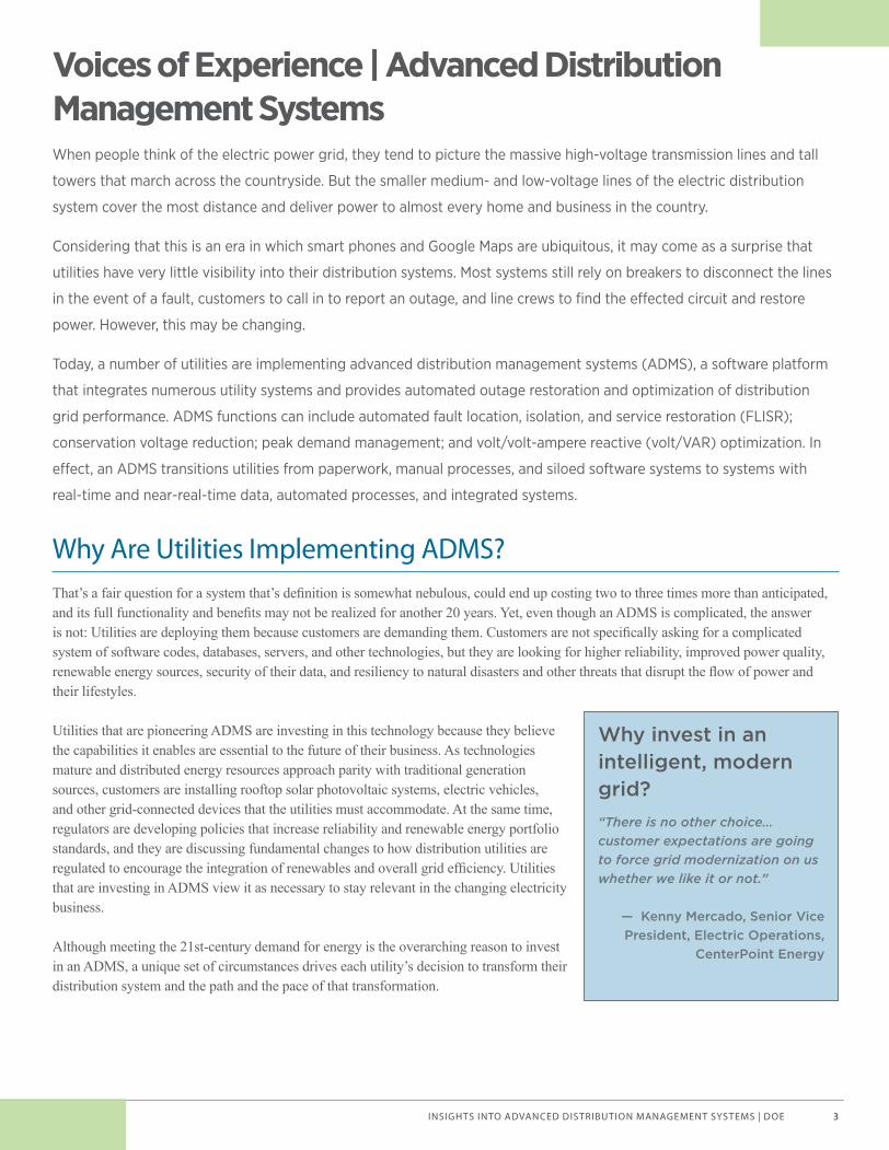
Why Are Utilities Implementing ADMS?That’s a fair question for a system that’s defi nition is somewhat nebulous, could end up costing two to three times more than anticipated, and its full functionality and benefi ts may not be realized for another 20 years. Yet, even though an ADMS is complicated, the answer is not: Utilities are deploying them because customers are demanding them. Customers are not specifi cally asking for a complicated system of software codes, databases, servers, and other technologies, but they are looking for higher reliability, improved power quality, renewable energy sources, security of their data, and resiliency to natural disasters and other threats that disrupt the fl ow of power and their lifestyles.
Utilities that are pioneering ADMS are investing in this technology because they believe the capabilities it enables are essential to the future of their business. As technologies mature and distributed energy resources approach parity with traditional generation sources, customers are installing rooftop solar photovoltaic systems, electric vehicles, and other grid-connected devices that the utilities must accommodate. At the same time, regulators are developing policies that increase reliability and renewable energy portfolio standards, and they are discussing fundamental changes to how distribution utilities are regulated to encourage the integration of renewables and overall grid effi ciency. Utilities that are investing in ADMS view it as necessary to stay relevant in the changing electricity business.
Although meeting the 21st-century demand for energy is the overarching reason to invest in an ADMS, a unique set of circumstances drives each utility’s decision to transform their distribution system and the path and the pace of that transformation.
Why invest in an intelligent, modern grid? “There is no other choice… customer expectations are going to force grid modernization on us whether we like it or not.”
— Kenny Mercado, Senior Vice President, Electric Operations,
CenterPoint Energy
Voices of Experience | Advanced Distribution Management Systems_brochure.indd 3 2/11/15 12:52 PM
INSIGHTS INTO ADVANCED DISTRIBUTION MANAGEMENT SYSTEMS | DOE4
The Reason for This GuideThe American Recovery and Reinvestment Act (ARRA) of 2009 spurred investments in smart grid technology and programs at utilities across the country. The Smart Grid Investment Grant program and Smart Grid Demonstration projects that it funded provided unprecedented opportunities to learn from smart grid implementation.
In 2011, the U.S. Department of Energy, Offi ce of Electricity Delivery and Energy Reliability (DOE OE), in partnership with electric utilities that received ARRA funds, convened a series of Regional Smart Grid Peer-to-Peer Workshops. These were designed to bring together utilities to engage in dialogues about the most compelling smart grid topics in each region. The meetings offered a platform for smart grid implementers at all stages of project deployment to share their experiences and learn from each other.
Realizing the benefi ts of bringing utilities together to share their experiences, in February 2014 DOE OE formed the ADMS Working Group by assembling a leadership team of representatives from the utility industry with the mission to collect the experiences, insights, and lessons learned from implementing these systems. This guide is the result of a one-day meeting held at CenterPoint Energy in Houston, Texas, in May 2014 that was followed by a series of conference calls about specifi c aspects of ADMS, interviews with individuals leading ADMS projects at their utilities, and a fi nal small group meeting at San Diego Gas & Electric in California in October 2014. The information in this guide came directly from the people in the industry on the leading edge of transforming their distribution systems. Although the working group included more than 40 people and represented 30 utilities and organizations, the following were key contributors of their experience:
· San Diego Gas & Electric (SDG&E)
· CenterPoint Energy (CPE)
· Austin Energy
· Duke Energy
· Kansas City Power & Light (KCP&L)
· Pacifi c Gas & Electric (PG&E)
We hope that sharing this information will help other utilities overcome or avoid some of the challenges these fi rst adopters identifi ed and be able to deploy their own ADMS successfully and effi ciently.
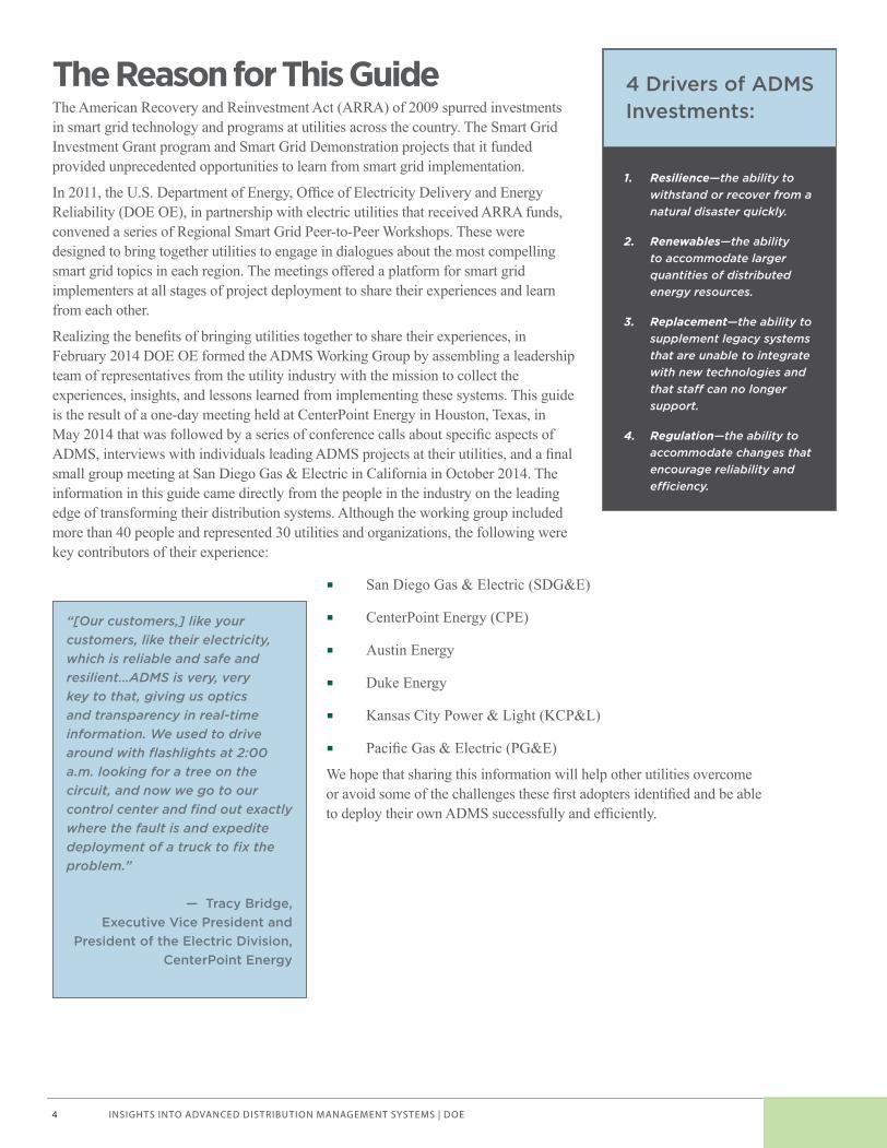
4 Drivers of ADMS Investments:
1. Resilience—the ability to withstand or recover from a natural disaster quickly.
2. Renewables—the ability to accommodate larger quantities of distributed energy resources.
3. Replacement—the ability to supplement legacy systems that are unable to integrate with new technologies and that sta� can no longer support.
4. Regulation—the ability to accommodate changes that encourage reliability and e� ciency.
“[Our customers,] like your customers, like their electricity, which is reliable and safe and resilient…ADMS is very, very key to that, giving us optics and transparency in real-time information. We used to drive around with fl ashlights at 2:00 a.m. looking for a tree on the circuit, and now we go to our control center and fi nd out exactly where the fault is and expedite deployment of a truck to fi x the problem.”
— Tracy Bridge, Executive Vice President and
President of the Electric Division, CenterPoint Energy
Voices of Experience | Advanced Distribution Management Systems_brochure.indd 4 2/11/15 12:52 PM

INSIGHTS INTO ADVANCED DISTRIBUTION MANAGEMENT SYSTEMS | DOE 5
Using This GuideThe goal of this guide is to provide practical advice to assist you in deploying an ADMS at your utility. Utilities that have deployed smart grid technologies have learned lessons and gained insights along the way—sometimes the hard way—that can be applied to new projects as well as existing projects that may be expanding or are presenting challenges. A few things to note:
· All utilities are different and have unique systems and requirements. This document is not a road map that must be followed; it is a compilation of advice and insights that other utilities have learned through their own ADMS deployments.
· A goal of this project was to capture information in the utilities’ own words. These are presented throughout the document in quotations and sections called “What We Did,” and “Looking Back—What We Learned.”
· Much of the advice and insights are not attributed to a single source, because they are summaries from group discussions. Likewise, some examples are not sourced to an individual or particular utility, because we wanted participants to speak freely about what they learned—even if they learned what not to do.
· Also, the working group identifi ed a number of resources that might be helpful as you embark on your ADMS implementation, including a number of documents produced by the Electric Power Research Institute (EPRI). The list provided below is not intended to be comprehensive, but it offers additional information that might be useful.
Additional Resouces—EPRI
• Guidebook for Cost/Benefi t Analysis of Smart Grid Demonstration Projects
• Program on Technology Innovation: Seamless Energy Management System, Part I: Assessment of Energy Management Systems and Key Technological Requirements
• Distribution Management Systems Planning Guide
• Integrating Smart Distributed Energy Resources with Distribution Management Systems
• Common Information Model (CIM) Conformity and Interoperability Test Procedure Development
• IntelliGrid Architecture Development for Distribution Systems
• Guidelines for Assisting Understanding and Use of IntelliGrid Architecture Recommendations: Distribution Operations
• Critical Needs for Distribution System Operations
What is an ADMS? “An advanced distribution management system (ADMS) is the software platform that supports the full suite of distribution management and optimization. An ADMS includes functions that automate outage restoration and optimize the performance of the distribution grid. ADMS functions being developed for electric utilities include fault location, isolation and restoration; volt/volt-ampere reactive optimization; conservation through voltage reduction; peak demand management; and support for microgrids and electric vehicles.”
— Gartner IT Glossary.
Source: EPRI
Voices of Experience | Advanced Distribution Management Systems_brochure.indd 5 2/11/15 12:52 PM
INSIGHTS INTO ADVANCED DISTRIBUTION MANAGEMENT SYSTEMS | DOE6
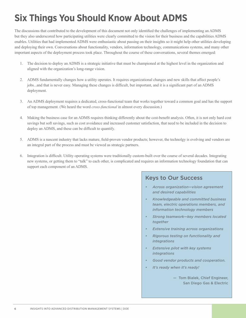
Keys to Our Success • Across organization—vision agreement
and desired capabilities
• Knowledgeable and committed business team, electric operations members, and information technology members
• Strong teamwork—key members located together
• Extensive training across organizations
• Rigorous testing on functionality and integrations
• Extensive pilot with key systems integrations
• Good vendor products and cooperation.
• It’s ready when it’s ready!
— Tom Bialek, Chief Engineer, San Diego Gas & Electric
Six Things You Should Know About ADMSThe discussions that contributed to the development of this document not only identifi ed the challenges of implementing an ADMS but they also underscored how participating utilities were clearly committed to the vision for their business and the capabilities ADMS enables. Utilities that had implemented ADMS were enthusiastic about passing on their insights so it might help other utilities developing and deploying their own. Conversations about functionality, vendors, information technology, communications systems, and many other important aspects of the deployment process took place. Throughout the course of these conversations, several themes emerged:
1. The decision to deploy an ADMS is a strategic initiative that must be championed at the highest level in the organization and aligned with the organization’s long-range vision.
2. ADMS fundamentally changes how a utility operates. It requires organizational changes and new skills that affect people’s jobs...and that is never easy. Managing these changes is diffi cult, but important, and it is a signifi cant part of an ADMS deployment.
3. An ADMS deployment requires a dedicated, cross-functional team that works together toward a common goal and has the support of top management. (We heard the word cross-functional in almost every discussion.)
4. Making the business case for an ADMS requires thinking differently about the cost-benefi t analysis. Often, it is not only hard cost savings but soft savings, such as cost avoidance and increased customer satisfaction, that need to be included in the decision to deploy an ADMS, and these can be diffi cult to quantify.
5. ADMS is a nascent industry that lacks mature, fi eld-proven vendor products; however, the technolgy is evolving and vendors are an integral part of the process and must be viewed as strategic partners.
6. Integration is diffi cult. Utility operating systems were traditionally custom-built over the course of several decades. Integrating new systems, or getting them to “talk” to each other, is complicated and requires an information technology foundation that can support each component of an ADMS.
Voices of Experience | Advanced Distribution Management Systems_brochure.indd 6 2/11/15 12:52 PM
INSIGHTS INTO ADVANCED DISTRIBUTION MANAGEMENT SYSTEMS | DOE 7
At a Glance Getting Started: Is This the Right Time? 8
Making the Business Case: Think Di� erently 10
Developing a Road Map: Plan Ahead 13
De� ning Your Requirements: Be Speci� c 15
Selecting a Vendor: Pick a Good Partner 18
Preparing Your Data: Clean It Up (and Keep It Clean) 22
Integrating Your Systems: Nothing Integrates Easily 27
Managing Change: Change Is Di� cult 30
Governing the Project: Key to Success 35
Appendix A: Requirements—Examples
B: Kansas City Power &
Light Distribution System Inventory
C: DOE Working Group Members
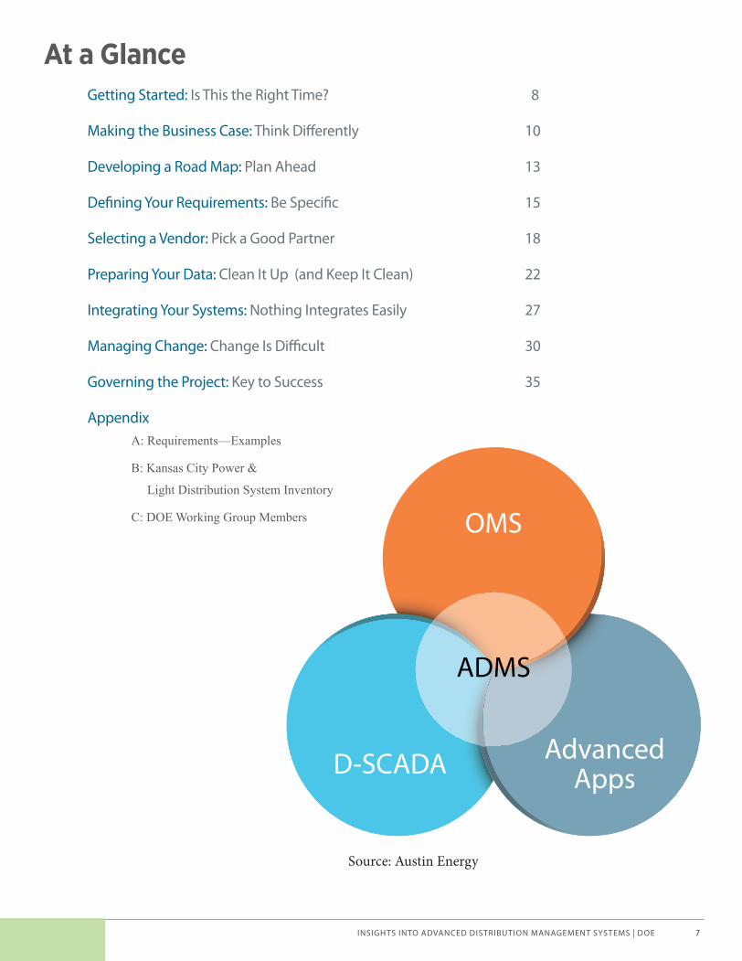
ADMS
OMS
Advanced AppsD-SCADA
Source: Austin Energy
Voices of Experience | Advanced Distribution Management Systems_brochure.indd 7 2/11/15 12:52 PM

INSIGHTS INTO ADVANCED DISTRIBUTION MANAGEMENT SYSTEMS | DOE8
Getting Started: Is This the Right Time?Utilities that are in the very early stages of planning or deciding whether to invest in an ADMS want to know when is the right time to start. So we asked the working group if there is a tipping point at which they knew they needed an ADMS. Not surprisingly, the answer was “It depends.” What it depends on is not only the vision of the utility, but also externalities—such as policies, weather events, and customer expectations—specifi c to each utility’s location or organization that impact (or could impact) the business. Some of the externalities mentioned by participating utilities include:
· Projections showing a growing number of rooftop solar photovoltaic systems;
· Local, state, or national policies requiring utilities to show a reduction in greenhouse gas emissions or an increase in the use of renewable generation;
· Analysis showing that enabling volt/VAR optimization capabilities is more cost-effective than acquiring or building additional peaking capacity;
· Having one or more legacy systems nearing the end of its life;
· Being located in a region where hurricanes or other severe weather events create frequent and extensive outages; and
· Changing customer expectations. The availability of new options and choices for customers means that a utility must meet new demands or risk decreasing customer satisfaction.
The decision to implement an ADMS starts with a vision of where the utility would like to be at some future date that is based on the externalities specifi c to the utility. In addition, clearly articulating the utility’s vision and end goals is important and needs to come from the executive leadership of the organization. Everyone working on the ADMS-including your vendors-must understand where the company is going and how it will operate in the future. And you need to think ahead. An ADMS deployment is a long and complex project. You do not want to wait until your current system fails.
Bottom line: Think ahead. It’s time to consider an ADMS when you foresee that your current system will not be able to respond to the externalities a� ecting your business in 5 to 10 years.
Insights · Business priorities unique to each utility will drive the design and timeline of your ADMS.
· There has to be a clear vision—from the executive leadership—for how the utility will operate in the future. A change in executive leadership may change the corporate vision and subsequently the requirements for your deployment plan.
· Vendors and utilities are learning together—both functionally and technically—as they implement ADMS. As the technology matures, some of these challenges may be resolved. The timing of your project will depend on your utility’s goals and the state of your existing system. For some, waiting is an option; but for others, it is not. (Note: No utility in the working group advised waiting for the technology to mature. If you keep waiting for the next version, you may never jump in.)
· Utilities need to evaluate smart grid technology similar to how they plan for future power needs; i.e., you don’t wait until you run out of power to build new generation. Implementing an ADMS tends to be a long-term project; it is not unusual for a utility spend two to four years implementing the technology. You don’t want to wait until after your current system fails to meet your needs to start your ADMS project.
· ADMS is an optimization tool. It is possible to do similar functions using other systems, but it cannot be done as well. Once implemented, an ADMS offers additional functionality that you cannot get following a traditional path of siloed systems.
· Like other capital projects, an ADMS deployment takes time—usually several years—and it requires time for planning. You do not want to wait until your current system fails to start considering an ADMS at your utility.
Voices of Experience | Advanced Distribution Management Systems_brochure.indd 8 2/11/15 12:52 PM
INSIGHTS INTO ADVANCED DISTRIBUTION MANAGEMENT SYSTEMS | DOE 9
Advice · Start early and dedicate a lot of resources.
· Think long term. Plans that look ahead 10, 20, and even 30 years are the norm. Utilities in the working group viewed ADMS as evolving to integrate all types of “stuff” that will try to disrupt their grid in the future.
· Start the project when the time is right for your organization. Do not wait until the next evolution of the technology; there will always be something new.
· Involve the right people—every business unit that will be using the system—in the planning stages. ADMS has a large number of interdependencies that cut across many departments. You have to break down those silos and bring people together.
· Front-load your project with time to develop use cases and other specifi cations. Planning is expensive and can be diffi cult to justify to executives, but it is key to a successful project.
· Include regulators in the conversation. The conversation may depend on the relationship you have with your regulator and what they think is important. If they need a business case that works from a fi nancial perspective, you need to give them that. You will also need to educate them on the technology and explain the benefi ts to them – this is a new product and the benefi ts might not be readily apparent.
· Build fl exibility into your project plan that allows for scope changes as the project progresses or new capabilities are desired.
· Include stopgaps and contingency plans throughout the multiple project plans so that when there is a slippage in one project the overall implementation can continue and isn’t held up by the delay.
Lessons Learned—InterfacesTreat interfaces as separate projects because they are huge, and that’s a big deal. ADMS implementation has a lot of interfaces—all those interfaces were all separate projects, and they should have been treated as such.
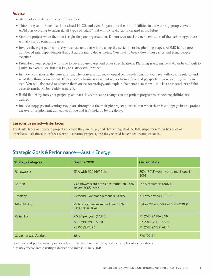
Strategic Goals & Performance—Austin Energy
Strategy Category Goal by 2020 Current State
Renewables 35% with 200 MW Solar 20% (2013)—on track to meet goal in 2016
Carbon CO2 power plant emissions reduction, 20% below 2005 levels
17.6% reduction (2012)
E� cieny Demand Side Management 800 MW 371 MW savings (2013)
A� ordability <2% rate increase, in the lower 50% of Texas retail sales
Below 2% and 50% of State (2013)
Reliability <0.80 per year (SAIFI)
<60 minutes (SAIDI)
<3.00 (SATLPI)
FY 2013 SAIFI—0.59
FY 2013 SAIDI—46.24
FY 2013 SATLPI—1.44
Customer Satisfaction 83% 71% (2013)
Strategic and performance goals such as these from Austin Energy are examples of externalities that may factor into a utility’s decision to invest in an ADMS.
Voices of Experience | Advanced Distribution Management Systems_brochure.indd 9 2/11/15 12:52 PM

INSIGHTS INTO ADVANCED DISTRIBUTION MANAGEMENT SYSTEMS | DOE10
Making the Business Case: Think Di� erentlyMaking the business case is one of the most signifi cant challenges associated with ADMS. An ADMS can be diffi cult to justify using traditional business case methodology that compares the cost of the technology to the cost savings or increased revenue associated with the benefi ts. Time frames for implementation tend to be long, and because it is an emerging technology, there is a lack of solid information about the true cost and the long-term benefi ts of this signifi cant investment.
Even so, the utilities that have implemented ADMS viewed it as a business strategy. It is a decision about how the utility will operate in the future and the functionality that will be needed to meet customer expectations—now and into the future. These utilities based their business cases on the value of increased reliability, societal and soft savings such as the ability to combine systems to provide optimization, run advanced applications, increased situational awareness, and others. And you have to ask, what are the benefi ts of getting information faster? Putting a value on these nontraditional elements can be a challenge, but it is necessary to make a strong business case for ADMS.
Bottom line: You have to think di� erently about your business case. An ADMS is not a technology that necessarily cuts costs; it adds capabilities and functionalities to support the company’s long-range vision.
Insights · Utilities are fi nding that when using traditional methods, the costs of the system can quickly outweigh the benefi ts largely because the benefi ts are incremental and already accounted for in other systems.
· Utilities must use nontraditional methods of determining benefi ts such as cost avoidance rather than relying on hard cost savings to make the business case. These savings can be diffi cult to identify and quantify and even more diffi cult to get others in the utility to accept as part of the analysis.
· Many of the intangible benefi ts such as faster outage response times, increased customer satisfaction, increased visibility, and other operational benefi ts that come from ADMS are diffi cult to quantify and can stall the business case and project implementation, but you are unlikely to make a positive business case without including them in the equations.
· The cost of an ADMS project has many variables including the level of integration (how seamless is seamless), the degree of accuracy of the data you require, the functionality you want, the size of your system, and the current accuracy of your GIS. (GIS is usually the system on which the model is based.)
· Operations and maintenance costs that are associated with new technologies once implementation is complete can be a signifi cant expense for the utility. Factor this into the budget and determine what can be capitalized up front.
Advice · Use available tools such as the Value of Service Study from the Lawrence Berkeley National Laboratory (LBNL) to help put a value on increased reliability. Then consider how increased reliability or faster recovery times contribute to increased customer satisfaction and what value can be placed on this.
· Work with your subject matter experts from each operational unit to identify the benefi ts of your proposed ADMS. It’s hard to quantify some of the things you don’t yet know exist, but it’s a necessary step. Get your team to think about what will be possible. This may take some time; one utility spent two weeks working through this exercise.
· Identify effi ciencies that can be gained by having an automated system in place rather than using multiple manual processes. For example, ADMS has been reported to be very helpful in identifying nested outages. Think about your own system and estimate how much time will be saved by not having to redeploy a second crew.
The Cost of a Power Outage “The U.S. Energy Information Administration estimates that the $150 billion in annual economic losses because of outages is equivalent to adding 4 cents per kWh of costs to consumers nationwide.”
— Annual Energy Outlook 2010, U.S. Department of Energy
Voices of Experience | Advanced Distribution Management Systems_brochure.indd 10 2/11/15 12:52 PM
INSIGHTS INTO ADVANCED DISTRIBUTION MANAGEMENT SYSTEMS | DOE 11
· Consider what happens to your organization when your ADMS implementation project is complete and your ADMS is operational. Does it reduce headcount? Or increase it? Do you need a more skilled workforce? A data scientist? Will additional support from IT or other business units be required?
· Estimate the cost to both obtain and then maintain the level of data model integrity that you have specifi ed. The cost of adopting processes and procedures needed to maintain the data on an ongoing basis is signifi cant.
· Include money to clean up your data. For example, you may need to verify that your GIS (if it is your system of record) is accurate and includes all the attributes of the distribution network that will be required for the ADMS.
· Include the cost and time to build a connectivity model for every single customer and every transformer. It is crucial to get the network model right and maintain it. Advanced applications require an accurate model.
· Beware of unintended consequences. Trying to tie the business case too closely to reliability increases alone is risky because with advanced metering infrastructure (AMI) outage notifi cations are received quicker so SAIDI/SAIFI numbers could increase because of more accurate reporting.
Looking Back—What We Learned
Unexpected Bene� ts · Initiate emergency voltage reduction faster (2.9% voltage reduction in 10 minutes); this is possible with SCADA but it’s faster with ADMS
· Initiate demand response from ADMS
· Integrate with microgrids
· Incorporate distributed energy resources and forecasted load into the load model
· Truly model distributed generation and not just negative load
Sta� ng
Utilities in the working group reported needing additional staff, and typically this staff required a different skill set—more information technology and electrical engineering skills. Plan for this up front. One company planned for one of the project team members to transition to the ADMS team once the implementation was complete. This allowed for increased buy-in and continuity.
Capital Cost vs. Rate Base
Some utilities were able to include ADMS as part of their rate case (e.g., Duke Energy); others self-funded the project and counted on improved operational effi ciencies (e.g., SDG&E). If you plan to include your ADMS implementation as part of your rate case, begin informing and educating your regulators early in the process—inlcude them in the conversation. You may need to include time in your project plan to help inform your regulator/board so they understand the value of the new system and how it can improve operations and benefi t customers.
Data Cleanup
I just urge anybody that’s starting out on this to recognize that you will fi nd one of those gaps that lead to your GIS data. Even if you’ve got good, clean data and you’ve got a good model, there will be land mines you can step on so just prepare your budget and schedule for that. Put months in there for GIS data cleanup.
Integration Costs
If I look back in time when we did the original business case, we ran out of money for most of the functionality specifi ed in the original business case. And really, that money was spent around the integration pieces. I would have included more money for integration.
Integration costs will probably be double or triple what you might expect.
Voices of Experience | Advanced Distribution Management Systems_brochure.indd 11 2/11/15 12:52 PM
INSIGHTS INTO ADVANCED DISTRIBUTION MANAGEMENT SYSTEMS | DOE12
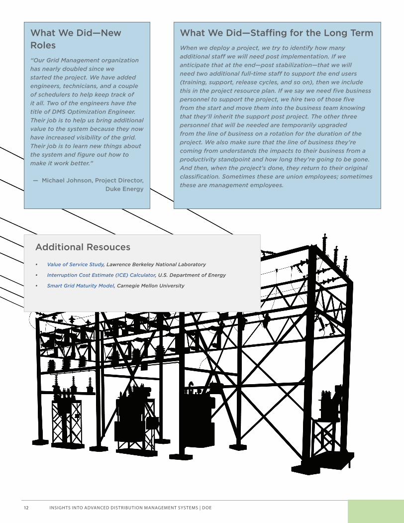
What We Did—New Roles “Our Grid Management organization has nearly doubled since we started the project. We have added engineers, technicians, and a couple of schedulers to help keep track of it all. Two of the engineers have the title of DMS Optimization Engineer. Their job is to help us bring additional value to the system because they now have increased visibility of the grid. Their job is to learn new things about the system and fi gure out how to make it work better.”
— Michael Johnson, Project Director, Duke Energy
What We Did—Sta� ng for the Long Term When we deploy a project, we try to identify how many additional sta� we will need post implementation. If we anticipate that at the end—post stabilization—that we will need two additional full-time sta� to support the end users (training, support, release cycles, and so on), then we include this in the project resource plan. If we say we need fi ve business personnel to support the project, we hire two of those fi ve from the start and move them into the business team knowing that they’ll inherit the support post project. The other three personnel that will be needed are temporarily upgraded from the line of business on a rotation for the duration of the project. We also make sure that the line of business they’re coming from understands the impacts to their business from a productivity standpoint and how long they’re going to be gone. And then, when the project’s done, they return to their original classifi cation. Sometimes these are union employees; sometimes these are management employees.
Additional Resouces
• Value of Service Study, Lawrence Berkeley National Laboratory
• Interruption Cost Estimate (ICE) Calculator, U.S. Department of Energy
• Smart Grid Maturity Model, Carnegie Mellon University
Voices of Experience | Advanced Distribution Management Systems_brochure.indd 12 2/11/15 12:52 PM
INSIGHTS INTO ADVANCED DISTRIBUTION MANAGEMENT SYSTEMS | DOE 13
Developing a Road Map: Plan AheadDeveloping a road map is a necessary exercise that is important not only for implementing an ADMS but for determining how the company will need to evolve to meet future customer needs. A road map will help stakeholders—including operators, engineers, and executives—better understand where the organization is headed, the technology that will be needed, and the value of that technology. An ADMS road map is a multifaceted plan that covers not only the technology and capabilities the utility would like to have at some point but also the resources—both human and fi nancial—needed to get there. There may be other technology road maps within or in addition to the ADMS road map, and all must align with the corporation’s long-range vision.
Participants in the working group stressed the importance of developing a road map and revisiting it often. Implementing complex systems like an ADMS can take several years to complete. Consider a 3- to 5-year plan for a typical ADMS, whereas, an IT road map should look 5, 10, and even 15 years out. Putting in the effort up front to develop a road map will pay off down the road. It will keep everyone “marching” down the same path and ensure that the capabilities are available when your utility needs them.
Bottom line: Don’t skip the road map. You need to know where you are going or you may end up heading down a path that you didn’t want to be on.
Insights · The road map is about the future capabilities your company will require and the technology needed to realize those capabilities.
· Some utilities develop an enterprise road map and consider their ADMS road map more of a project plan. The enterprise road map ensures that technology investments are aligned with the corporate strategy.
· The road map sets the expectations for deliverables and time frames for development. It can help your organization defi ne the sophistication of the system and the level of integration you are expecting. It will also help you manage the expectations of your executive team.
· Developing a road map requires dedicated resources, and it needs to be “owned” by both the IT department and business planning group. Ownership of the road map can be a challenge for utilities due to the historically siloed nature of departments, but it can also help bridge the silos among departments.
· Many systems—such as meters, outage reporting; outage management, SCADA, FLISR—are generally not owned by the same business or IT group. It is important to periodically confi rm that their road maps align with the systems you own. Everyone needs to understand the expectations around deliverables and schedules from their road maps and how those might impact the ADMS road map.
· A road map will also provide benchmarks that can help with vendor selection. Ensure that your vendor’s road map is aligned with yours so that the vendor you choose will have the capabilities you want in the time frame you have identifi ed.
Advice · Review your corporate vision (or road map) and current competencies, then think about what capabilities you want to deliver and the technology required to deliver them.
· Consider developing two road maps—one for technology and a separate one for the business—then make sure they align.
· Recognize that although it is diffi cult to plan 10 to 15 years out, you need to look that far ahead. An ADMS lays the foundation for the capabilities you will need in the future.
· Develop a road map of capabilities and then create a technology portfolio of projects to enable them, including identifying the equipment or other devices that will be needed to achieve desired functionalities.
Voices of Experience | Advanced Distribution Management Systems_brochure.indd 13 2/11/15 12:52 PM
INSIGHTS INTO ADVANCED DISTRIBUTION MANAGEMENT SYSTEMS | DOE14
· Take a holistic approach. Don’t look at only the ADMS product, but consider how ADMS and its functionalities fi t into the corporate vision. Having an advanced functionality but not being able to utilize it for 10 years—especially if a lot of interfacing is required to make that happen—may not be the best use of your resources. The corollary is also true: You may realize you need a particular functionality sooner rather than later, and it takes years to implement an ADMS.
· Include technology upgrades that are needed to existing systems, such as to your GIS. Likewise, there are many options for fi eld communication systems. Think this through early in your planning process to determine what you want or need now and into the future.
· Involve all departments that will use the system in the road map development process, including IT, business planning, fi eld crews, engineers, operators, and even fi nance, human resources (HR), and regulatory colleagues. Involving these departments up front helps achieve long-term buy-in and allows the perspectives and needs of all departments to be incorporated.
· Specify future workforce needs, changing skill sets, and how those skills will be developed or acquired. This will also help determine when you are going to need to hire new staff or provide training to existing staff and areas where you may benefi t from some change management expertise.
· Involve HR in the process to ensure that the appropriate resources are available at the right time. This may include hiring people with the right skills and reintegrating staff as they roll off the deployment project.
· Consider the changing needs of your fi eld workforce. Look at what skills will be needed for an ADMS and how those skills will be developed or acquired. More IT skills might be needed, but the individuals with these technology skills might not have the skills linemen need (such as how to use a wrench).
· Build in fl exibility. The capabilities you desire will determine choices you make in regard to your ADMS. Make sure your system is fl exible enough to add new capabilities in the future.
· Perform regular (quarterly or biannual) reviews and updates of your road map to make sure new functionalities are added (technology changes fast). As the new systems and functionalities are deployed, the road map needs to be updated with the new processes and staff requirements as well.
Looking Back—What We Learned
Worth the E� ort
If you’re earlier in the process, and going through the diffi culties in taking the time to develop your road map, you might ask yourself, “Is this really worth the amount of effort I’m putting in?” Being on the back end of it now, I would say yes. Then I would ask another question. If I were to go back in time and talk to myself seven years ago, for example, I might ask, “Well, how much is too much?” And if I ask myself that question now, I don’t know that we’ve hit that point. I don’t know that there is a ‘too much.’ Meaning, is there ever too much effort that you put into your road map or to your project plan? We haven’t hit that yet.
Planning
I wish we’d followed our plan maybe a little bit better. We have a plan. We have a road map, but then things kind of got dropped into that road map from on high and they didn’t always mesh with the plan that we had laid out, so we just have to squeeze it in and absorb it. But sometimes I wish we did a better job of following our plan.
Schedule
What I think I would have done differently, or tried to get done differently, is to develop a schedule, but I would’ve built fl oat into it, using project management terms and decision points, so management knows when there will be a proof-of-concept phase, and there’s a staggered rollout, and the schedule can change from there based on what you’ve learned at that point. Those are key things that we could have done better on our project a few years ago.
Deployment Time
We realized it was going to take 5 to 10 times longer to deploy than we had planned.
Voices of Experience | Advanced Distribution Management Systems_brochure.indd 14 2/11/15 12:52 PM

INSIGHTS INTO ADVANCED DISTRIBUTION MANAGEMENT SYSTEMS | DOE 15
Defi ning Your Requirements: Be Specifi cWhat functionality do you want your system to have? The functional requirements will defi ne what will be included in your ADMS. This needs to be a very detailed list. The more specifi c you are, the better chance you have of getting what you envision. Utilities in the working group listed many requirements—from 1,500 to more than 4,200—in their request for proposals (RFPs). Your list of requirements will depend on what systems and functionalities you include in your ADMS.
Developing use cases that map how information will be used—by who, when, where, and why—will help you to more accurately defi ne your requirements and help ensure that nothing is forgotten or left out. High-level use cases are the blueprint that will help you defi ne the requirements for your RFP. Pick your vendor based on road map compatibility, then use your detailed requirements and use cases to determine fi nal pricing and deliverables.
Bottom line: Success is in the details. Specifying your requirements and developing use cases for your system is key to getting the end result you want.
Insights · Your requirements will be driven by the corporate vision and road map. Examples of requirements are included in Appendix A.
· Use cases are the foundation of ADMS development. They document the process, the input, and the output. Use them to evaluate the systems and how to make them work together.
· Requirements may be subject to interpretation both internally and externally. Your understanding of a requirement may not be the same as your vendor’s understanding of that same requirement. This can cause (huge) problems during implementation.
· Some utilities found it useful to hire a consultant to help with this process. It is a signifi cant effort, and the consultants may have knowledge and expertise you do not have within your staff or might be able to help individuals better articulate what will be needed. A consultant who won’t be bidding on your ADMS project but who has helped other utilities defi ne their requirements may be able to provide a baseline of requirements that could help you jump-start the process and save time.
Advice · Take the time up front to clearly defi ne your system requirements and develop your use cases. This can be a lengthy and somewhat costly process, but it could end up saving time and money further into your deployment.
· Think about everything you might want to do in the future, as well as everything you do today, and how can you do it better. Put that in your requirements. If you don’t, in the future you might fi nd yourself boxed into a solution and unable to expand to achieve the functionalities you want.
· Use detailed and specifi c language to describe your requirement in both the RFP and contract.
· Include people from all affected departments—operations, systems and control engineering, IT, planning, business, and so on. If a group has a hard time specifying requirements, enlist a liaison. Include individuals familiar with the independent modules as well as direct users and information architects.
· Include operators in the process. They need to be actively involved, because they will be using the ADMS. This will help increase buy-in, and it’s valuable to get their perspective on what works for them.
· Evaluate the modules already in place and determine how the utility wants to integrate those functions.
· Look at the functionalities of your legacy systems. Determine what functionalities from those systems must continue to be included in the ADMS. Sometimes an old functionality may get lost—and this might be okay—but make sure the functionality that is critical is identifi ed and kept.
Voices of Experience | Advanced Distribution Management Systems_brochure.indd 15 2/11/15 12:52 PM
INSIGHTS INTO ADVANCED DISTRIBUTION MANAGEMENT SYSTEMS | DOE16
· Determine who and what is involved with using the new system. For example, What reports will need to use data from the model? How will it be characterized?
· Defi ne early on the role of ADMS versus the role of OMS. Will your OMS load fl ow feed to your ADMS?
· Determine what components will be done in-house and what will be handled by the vendor.
· After selecting a vendor, but before signing a contract, sit down with your vendor and talk through the requirements—preferably with the developers and not only sales people—to make sure they are interpreting the requirements the way you intend and can deliver a system to meet your specifi cations. (If a misunderstanding is exposed later in the project, the resolution process can be contentious.)
· Push hard on vendors for “use case” support. Writing use cases is a joint task between utility and vendor because implementing vendor algorithms is different for each operating environment.
Looking Back—What We Learned
Write Detailed Requirements“We consider all of the vendors that we’ve worked with partners, and we are able to have conversations with them. In most cases, when we say, ‘Hey, we want this to happen,’ they work with us to make sure that they understand what we’re talking about and that we’re all saying the same thing. So you get to the point where your contract says whatever the language is, and we think it says this, and the vendor thinks it says something different. We push back and say, ‘Oh, you’re reading this too much line by line, word by word, and that wasn’t the intent.’ So don’t assume intent on those things. One of the skills I believe we acquired as a company through our smart grid project was being able to gather better business requirements. So when I say, ‘I want these two systems synchronized,’ what I really want is to see the same data at the same time and to be able to ask questions about what that actually means, to be able to probe and get what it means so a developer could actually develop something off of it. It’s challenging. The more time you spend on defi ning that stuff, the less painful it is down the road.” —Andrea Dennis, Manager Distribution Operations, OGE
Develop Good Business Requirements
I would say one of the biggest lessons learned—or one of the things that we learned throughout the project—was the importance of developing good business requirements and use cases.
Spend More Time on Requirements
We would have spent more time defi ning requirements, and we would have done a better job of putting those in the contract. If we had better defi ned requirements, we would have had a better contract. We still have contention points today about requirements.
Voices of Experience | Advanced Distribution Management Systems_brochure.indd 16 2/11/15 12:52 PM

INSIGHTS INTO ADVANCED DISTRIBUTION MANAGEMENT SYSTEMS | DOE 17
Writing Use Cases—Example
A use case is a software and system engineering term that describes how a user uses a system to accomplish a particular goal. A use case acts as a software modeling technique that defi nes the features to be implemented and the resolution of any errors that may be encountered.
Use cases defi ne interactions among external actors and the system to attain particular goals. Three basic elements comprise a use case:
· Actors: Actors are the type of users that interact with the system.
· System: Use cases capture functional requirements that specify the intended behavior of the system.
· Goals: Use cases are typically initiated by a user to fulfi ll goals describing the activities and variants involved in attaining the goal.
Use cases are modeled using unifi ed modeling language and are represented by ovals containing the names of the use case. Actors are represented using lines with the name of the actor written below the line. To represent an actor’s participation in a system, a line is drawn between the actor and the use case. Boxes around the use case represent the system boundary.
Characteristics associated with use cases are: · Organizing functional requirements
· Modeling the goals of system user interactions
· Recording scenarios from trigger events to ultimate goals
· Describing the basic course of actions and exceptional fl ow of events
· Permitting a user to access the functionality of another event
The steps in designing use cases are: · Identifying the users of the system
· Creating a user profi le for each category of users. This includes all roles played by the users relevant to the system.
· Identifying signifi cant goals associated with each role to support the system. The system’s value proposition identifi es the signifi cant role.
· Creating use cases for every goal associated with a use case template and maintaining the same abstraction level throughout the use case. Higher-level use case steps are treated as goals for the lower level.
· Structuring the use cases
Review and validate the users.
Source: Posted on Techopedi.com by Cory Janssen
Voices of Experience | Advanced Distribution Management Systems_brochure.indd 17 2/11/15 12:52 PM
INSIGHTS INTO ADVANCED DISTRIBUTION MANAGEMENT SYSTEMS | DOE18
Selecting a Vendor: Pick a Good PartnerSelecting and working with vendors was one of the topics that permeated nearly every working group discussion. The relationship you develop with your vendor is a very important part of the ADMS. You and your ADMS vendor will essentially be in long-term partnership—possibly 20 years—so make sure you select a good partner.
Developing an RFP and selecting a vendor for your ADMS can be a long process. The stakes are high, and mistakes can be costly, so take your time and commit the necessary resources to the process—including developing the RFP. Pick the company that can best fulfi ll your requirements and has demonstrated that they are committed to not only winning your business but providing service for the long term.
Bottom line: Take your time, pick a good partner, and then make it work.
Insights · Vendor products are at various stages of development. Know your vendor’s capabilities and their product development road map; make sure it matches your technology road map. The functionalities you want should align with the timing in the vendor road map.
· You will get what you ask for. If you want a specifi c functionality in your fi nal system, include it in your RFP. Do not assume that any capabilities, functionalities, or services are included unless they are specifi ed in the RFP and subsequent contract.
· Capabilities and functionalities are subject to interpretation. Your RFP and contract must be specifi c, and you need to make sure your vendor understands your requirements the same as you do. Interpretation is critical!
· Confi guration is preferable over a custom product. If you are requiring heavy modifi cations to the vendor’s base product, make sure you know if they consider your confi guration a “custom product” or a new version of their standard offering. This will impact how the vendor will provide support and maintenance after implementation.
· Even though a vendor may offer a full suite of products, they may not be fully integrated. Companies offering a software suite may include products acquired through mergers and acquisitions that are not necessarily compatible.
Advice · Engage a cross-functional team in the RFP development process. Include subject matter experts in planning, management, operators, fi eld personnel, systems and control engineering, and IT. Include every business unit that will be impacted by the ADMS or that is involved in the legacy system being replaced by or integrated into the ADMS. Involving all of these groups will help ensure the development of a more complete list of requirements. It is key to include the operators because they will be the ones using the system.
· Include requirements that depend on another supplier in the main vendor language. If the vendor needs that equipment/product to meet their deliverable, include it in their contract.
· Visit other utilities that are using the vendors that your are considering and ask questions not only about the vendor’s products but also their responsiveness to changes and commitment to the project.
· Consider including a small pilot prior to full-scale implementation to test it out. Possibly run two pilots simultaneously with two different products to determine which one more closely meets your needs.
· Have your operators review and “play” with a sample model from the vendors you are considering. Set up a model in your operations center. This will help operators understand the nuances of each system and will also give them an idea of what is possible, which can help buy-in.
Voices of Experience | Advanced Distribution Management Systems_brochure.indd 18 2/11/15 12:52 PM

INSIGHTS INTO ADVANCED DISTRIBUTION MANAGEMENT SYSTEMS | DOE 19
· Spell out everything in the contract. (Don’t assume anything!) For example, specify by name the vendor personnel that will support your project, how many hours per month or week they will be on-site, and how quickly they must respond. This might seem like overkill, but it was a resounding item with the utilities in the working group. One utility included an entire chapter on vendor personnel in their contract.
· Ask to have separate production and development environments so that employees can train on the new system without effecting operations.
· Pick a partner that will be able to focus on your project and dedicate the attention the project will require—this is especially important for smaller utilities.
· Provide each prospective vendor with a data set (usually from your GIS) and have them provide an on-site demonstration using your data. By having a demo with your own data, the vendor selection team will be familiar with it and will be able to better understand how the product works—or doesn’t work.
· During the demo, choose individuals from your team who are “opinionated” and aren’t afraid to ask questions so that issues can surface and be addressed early in the process.
· Do not assume products are compatible or will integrate easily—even if they come from the same vendor. Ask specifi cally about integration, and have the vendor demonstrate compatibility.
· After selecting a vendor, but before signing the contract, fund work for a detailed review of the requirements with your vendor (this could take a week or more). It’s important to know that you and your vendor understand the requirements the same way. Make sure product developers—not only the sales team—are part of the discussion.
· Make sure your contract includes a long-term maintenance plan and upgrades to the product.
· This should go without being said, but look beyond the graphics interface of the product and base your decision on sound technical reasons. It might “look” like a product has a specifi c capability based on the interface, but make sure you actually see it work.
What We Learned—Elements of the Contract
Finance · Include milestones and pay for performance. Require a critical path schedule and periodic updates throughout the project. Consider whether the project will be implemented all at one time or in stages.
· Backload the contract as much as possible to provide an incentive for the vendor to meet the specifi ed time line for deliverables. You may also want to negotiate a holdback of 10% for one year, to make sure you get the support you need after the system goes live, which is essentially a warranty that you write into the contract.
Personnel · Specify personnel (by name) you want working on your project and that a personnel change requires utility concurrence. Include how many hours they will be on-site each week or month.
· Require key personnel to participate in contract negotiations.
· Specify how support will be handled and how quickly the vendor must respond.
· Require participation (either by phone or in person) of vendor personnel in project team meetings.
· Require biweekly meetings with utility and vendor executive teams to discuss the status of the project, issues, and resolution, especially if the product is not yet mature. This might increase to weekly meetings when nearing the go-live date.
Voices of Experience | Advanced Distribution Management Systems_brochure.indd 19 2/11/15 12:52 PM

INSIGHTS INTO ADVANCED DISTRIBUTION MANAGEMENT SYSTEMS | DOE20
Scope of Work · Articulate clearly and completely the scope of work—and don’t change it!
· Identify whether the scope includes all distribution networks, including overhead, underground, three-phase, substation, and so on.
· Develop a detailed list of every system and/or report that does or might interface with the ADMS—for example, GIS, SAP, mobile data.
· Specify the application program interface, in-circuit programing, or other connections you desire and their purpose.
· When specifying compatible products, include not only the same type but identify the version.
· Include compatibility testing requirements.
· Identify the communication systems for all your grid-operable items and specify the department responsible for designing and providing the connectivity.
· Provide details on the GIS interface and how often it will be updated.
· Understand AMS meter data usage and specify what you intend to do with it.
· Include a vulnerability testing requirement.
· Include product testing requirements.
Hardware · Specify who buys it.
· Defi ne architecture.
· Sandbox
· Question-and-answer box
· Main system
· Backup system
· Dual redundancy
· What does 99.99% availability mean?
· Specify whether any down time is allowed and for how long.
· How will software uploads be handled and when can they take place?
· Security/NERCIP aspects
· How many monitors does it support?
· Specify maintenance expectations.
· Specify the service levels desired. Specify names, whether there is phone or on-site support, and how frequently someone must be on-site. Specify the required response times. If there are issues on the weekend or after hours, what level of support will the vendor provide?
· Who is responsible for third-party vendor patches?
· How often are updates allowed?
Sizing Considerations · Now plus future growth (10–20 years from now)
· Capacity testing criteria
Voices of Experience | Advanced Distribution Management Systems_brochure.indd 20 2/11/15 12:52 PM
INSIGHTS INTO ADVANCED DISTRIBUTION MANAGEMENT SYSTEMS | DOE 21
· Performance testing criteria
· EOP event sizing
· How quickly the system recalculates and presents data
Reporting · Defi ne the scope and timing expectations of your management.
· Understand and articulate all business aspects and make sure these are clear.
Software/Implementation · Is software proprietary? If so, it might limit your ability to fi nd additional resources if the project gets in trouble. Make provisions for this and how it will be handled.
· What system does it run on? For example, Windows 7 or 8? Linux?
· What software does the vendor support and which versions? How long do they support each version? When versions of supporting software change, how does that impact the ADMS?
What We Did—On-Site Demonstration
Austin Energy’s ADMS, which went live in June 2014, fi rst started with a pilot DMS project in 2008. The piloted system was a European product adapted to fi t the U.S. market. Austin Energy successfully completed their DMS pilot but realized some of the limitations of a stand-alone DMS, and therefore decided to sit it out for a couple of years to see how the market might evolve.
In 2011, Austin Energy released an ADMS RFP. The RFP, developed with the help of a consulting fi rm, was a 500-page document containing 4,200 requirements. Hiring a consultant to develop a general ADMS specifi cation based on stand-alone OMS, DMS, and SCADA projects expedited the process and was less daunting than starting from scratch, but it still required a signifi cant effort because ADMS merges all these functionalities. The Austin Energy team—11 people that included individuals from planning, system engineering, control engineering, and operations—spent about a month reviewing and editing the RFP to tailor it to Austin Energy’s needs.
Four vendors returned proposals by the deadline and were invited for an on-site demonstration. The idea was that a demonstration using Austin Energy’s own data would help the review team better understand the capabilities of the product.
For the demonstration, Austin Energy supplied each vendor a shape fi le export from their GIS and a separate electrical characteristics database for four circuits that could be tied together so it would be possible to test mesh analysis, switching operations, and other advanced functionalities. Each vendor was given three weeks to prepare and was scheduled for an eight-hour demonstration.
For the demonstration, Austin Energy brought in a number of individuals—most from the requirements team—who were not afraid of speaking up and willing to ask a lot of questions to help them understand the capabilities of each product and to make sure that they were understanding the functionalities in the same way as the vendor. In the end, only one of the four vendors was able to successfully demonstrate the majority of the functionalities requested by utilizing Austin Energy’s data.
The bottom line is that anyone can put something on paper and do a great presentation, but a demonstration using your own data will quickly tell you who has a real product and who is still in the development phase. Giving the vendor a cut of your data and having an on-site demonstration will give you a better understanding of how the product will work on your system and some of the issues you are likely to encounter during your deployment. In addition, the effort on the vendors’ part is signifi cant and may tell you who really wants your business—something especially important for smaller utilities.
Voices of Experience | Advanced Distribution Management Systems_brochure.indd 21 2/11/15 12:52 PM
INSIGHTS INTO ADVANCED DISTRIBUTION MANAGEMENT SYSTEMS | DOE22
Preparing Your Data: Clean It Up (and Keep It Clean)The foundation of an ADMS is the data. The ADMS is a control hub, and it must have accurate data to correctly model your system. Data collection and maintenance in your GIS is critical to your ADMS implementation, and business processes to maintain clean data is just as important.
Utilities deploying ADMS spent signifi cant resources and time developing clean data by inventorying their systems and developing processes to ensure that data integrity is maintained. In addition, signifi cant foundational investments in information, communications, and operational systems may be required to support the security, access, and storage of your data. The data management strategy you deploy depends on the security level needed for various types of data, the level of integration you want, and the future capabilities you have planned. And, like other aspects of an ADMS project, data management drives change management—organizational responsibilities have to adapt to meet your new data requirements.
Bottom line: If you want your state information to work well, your model must accurately represent what is actually on your system. That means you need good data.
Insights · Each level of ADMS sophistication will require additional information that was never needed or collected before and will require greater accuracy to achieve that functionality. For example, outage analysis load fl ow calculations require information about wire sizes, conductivity, and so on, and being able to notify specifi c customers of outages will require information on the exact phasing of each transformer.
· Even if you think your GIS is “clean,” it probably isn’t clean enough for ADMS. Utilities reported that even when they thought they had clean GIS data, there was still a lot of work to do to get it accurate enough for the ADMS. Remember, the model will only be as good as the data in your GIS.
· Data cleanup and data mapping can be a substantial effort. It could take many months to complete and amount to 10% to 25% of your ADMS project costs. Some utilities in the working group recommended that you consider it a separate project.
· Processes need to be in place to keep the data current during normal operations. You might fi nd resistance to this from fi eld crews, but it’s important to identify who is responsible for keeping the data accurate and hold their management accountable.
· The more granular and accurate your data, the more robust your communications system will need to be. Additional capacity on the communications system may be required to support data from your ADMS. Upgrading foundational IT systems to support an ADMS can be expensive; it may require a signifi cant capital investment and take years to complete depending on the size of your system and its current state.
· Data management is a signifi cant and ongoing cost and effort. Having a global corporate strategy for data management can help you weigh the costs verses the benefi ts of your options for sharing, accessing, and storing data.
Advice · Start developing a strategy for managing and storing data early in the planning process.
· Involve end users, IT, engineering, and business units in data design. Distribution engineers and control center personnel should be involved in data discussions.
· Know what data is collected in your GIS. It may have been built to support OMS, so data was collected only if it was needed for the OMS. New data may need to be collected to support an ADMS.
· Ensure that the system is accurately mapped before beginning your project. Collect and document information on every transformer phase to make sure that the connectivity is accurately documented, because any failures will be picked up by the ADMS model. Correct and document mapping errors.
Voices of Experience | Advanced Distribution Management Systems_brochure.indd 22 2/11/15 12:52 PM

INSIGHTS INTO ADVANCED DISTRIBUTION MANAGEMENT SYSTEMS | DOE 23
· Make GIS data cleanup a separate project. Don’t roll it into your ADMS implementation.
· Do a thorough inventory. Know exactly what you want inventoried and what data you’re going to need. Then fi gure out how it’s going to happen and how to maintain accuracy.
· Modeling distribution attributes is crucial. Information that wasn’t important before—such as phasing, connectivity, and wire size—is now critical for model integrity. You may even have to modify the graphic symbols in the model to identify nodes. This was an issue with load fl ow analysis for one utility.
· Decide where your model will start—at the substation or at the transformer? One utility originally started their model at the substation breaker but during implementation decided to start at the high side of the station power transformer and modeled everything within the substation.
· Develop a process for accurately collecting changes in the fi eld and how those changes will be transferred and documented for the model. Field crews make daily modifi cations, and these have to be captured accurately.
· Develop a process for capturing changes during large-scale outages when mutual assistance crews come in to help restore the lines. With mutual assistance crews, the priority is usually quick restoration, but capturing fi eld changes is critical for model integrity.
· Design your communications infrastructure to allow for additional data requirements. As your system evolves, each level of sophistication will need data that was never collected before and may require additional capacity on the communications system.
· Do a futuristic data exercise to determine what data might be needed. Look at the life cycle of data and the communications infrastructure to determine what and how much data there will be so the system can be correctly sized. One utility is collecting 6 data points at the substation breaker and bringing that back. On some locations, they are bringing back 100 or more points.
· Your data architecture should have good touch and transfer points for data and the ability to silo data so that working in one system will not harm other, interconnected systems.
· Specify what data will be needed—for reporting, measuring performance, for different functionalities such as CVR, volt/VAR, etc.—how it will be used, how it will be stored and for how long, and who will need access to it. Your engineers may want everything, but it is prudent to build your design around “useful” data points.
· To help reduce or eliminate confl icts and to work out any data issues, use a phased approach. Test and validate your data at each phase before moving on to the next.
· The goal is to have one standardized language, but in reality you may need to use two or three for different groups.
· Understand the algorithms so you are collecting and utilizing the right data to make the analytics useful to your utility.
· Data design should be an iterative process. As you add applications, you will need to go back and map your data points again. And as you implement, issues around data will arise that will need to be addressed.
· Include your vendor in company discussions about your data requirements. Your vendor may have a specifi c idea of how the data will be viewed, but it might not match your data characteristics. In addition, vendors might not be aware of the type of data you have available and how that could be leveraged for the functionality you want to incorporate
· Work with your vendor regarding how data is historicized (create an archive copy or journal when data is updated or deleted). Keep short-term (for operations) and long-term (to archive or for reporting) data in two separate areas so there aren’t latency issues. Also, make your vendor aware of your existing data repository, if it is available, and discuss how it could be leveraged.
· The amount of data you have to store can be an issue. Prepare for the volume of data that will be coming in. One utility decided to go offsite to a data farm and expressed being surprised by the amount of data to store. Similarly, another utility mentioned being surprised by how much they needed to spend on random-access memory.
· Also, hang on to your paper maps. Although IT systems are typically built with a signifi cant level of redundancy, they can fail. So keep your paper maps and keep them up to date as a backup for your electronic system.
Voices of Experience | Advanced Distribution Management Systems_brochure.indd 23 2/11/15 12:52 PM
INSIGHTS INTO ADVANCED DISTRIBUTION MANAGEMENT SYSTEMS | DOE24
Looking Back—What We Learned
Costs
It costs approximately $25 to $30/pole to do a walk down to validate GPS location, put an identifi er tag on a pole, take a photo, capture wire sizing and brand information, check connectivity and phasing, validate wire sizing, trace it to the customer, and validate meter numbers.
Modeling the System Is Not Easy!
We started this project more than six years ago, in early 2008. We had a lot of fi eldwork to do and a lot of substation work to do. And that’s been done for about two years, so that was actually the easy part. It took us about four years to deploy all that work. But we’re still fi nishing the DMS itself, we’re still working on this thing, we’re still patching it, and we signed the contract in April 2009, so that’s been fi ve years. And, again, a similar kind of story, our plan was to do it completely by the end of 2012. So we gave ourselves three and a half years and still didn’t hit that time line. So, what is the biggest driver? The model. We thought we had a large amount of work to do and then a couple years into it we realized that we needed to double the resources on the project team to get the model correct. And then we went another year and doubled it again. So I think if you have an idea that you have a lot of model work to do and you’re at the beginning of the project, you should probably think you’ve got 5 to 10 times the amount of work that you think you have. And that’s only a slight exaggeration. It’s an enormous undertaking to get real-time state estimation working on your whole network.
Model the Substations
Doing it over, I would model the substations in the GIS.
Mapping Your System
It took us one and a half years to go out and collect phase information on every transformer and build a connectivity model for every single customer for every transformer. We identifi ed about 44,000 mapping errors in our GIS. There are about 200 circuits that are affected by those, and we’re about 90 percent done today. We’re working our way through the system, so we’ll fi nish that by the middle or so of next year.
It’s really the GIS technician that needs to make sure that there’s perfect connectivity going through and that the connectivity follows the right attributes all the way through every transformer, every switch, every fuse, every electrically connected device in our system, because any failures in the connectivity model get picked up in the ADMS.
Pushing vs. Polling
One of the problems we found was that when you go out to specify distribution equipment, these things are set up not to be polled for information, but to push information. So they’re broadcasting. We found that it jammed up our DMS, because we weren’t set up to poll, we were just set up to accept, so it was sitting there fl ooding the DMS. We had to shut that part of the system down for a little while, go back, and then set up a polling protocol and actually slow down the data acquisition. So it was the opposite problem of what you would expect. And this was for only nine of our feeders, and it was choking the system. And 40 remote points were constantly pushing data.
Voices of Experience | Advanced Distribution Management Systems_brochure.indd 24 2/11/15 12:52 PM
INSIGHTS INTO ADVANCED DISTRIBUTION MANAGEMENT SYSTEMS | DOE 25
What We Did—Keeping the Data Current
Our process is that the crews in the fi eld have to tell us what the connectivity is. They have to build it the way it’s designed, and they need to communicate what’s different about it. We also have some phase detection devices that a line mechanic can hang on the pole to determine the phase. We took the devices leftover from the project implementation and located them in every single service center. Each service center is required to check 10 discreet locations per week—that’s two a day—and so far that has given us about a 95 to 96 percent success rate (they’re tracking matches now in GIS, so that’s really good). We’ve decided to double the number of phase-detection devices we have, because the scheduling to make sure that the right crews always have them is a bit cumbersome, and the devices are kind of expensive. We’re putting them on big crews, what we call construction crews, so any time a construction crew is out they are obligated to check and make sure they revalidate that it’s correct as built or that it’s wrong as built.
What We Did—Walked Our System
As we worked through how ADMS would perform analysis, we realized that without accurate phasing information, you cannot get the full functionality out of an ADMS. You can make assumption about phasing, but your model will not be accurate. If you want to be able to notify customers about outages (that was one of our objectives), you need to know which phase of each circuit each customer is tied to.
About a year into the project, we decided to pause our project and walk our system to determine the phase of conductors at every pole where there was a transition. This was done with a skilled union worker using a hot stick on the conductor to determine the phase that was then stenciled on the pole. This was followed by a technician who entered the stenciled information into the GIS. We bought two detection tools for each service territory to do regular spot checks to make sure GIS is accurate. It can quickly become inaccurate if you not have quality assurance processes in place. Walking our system was a huge effort that we had not included in our original schedule, but necessary to get accurate data.
Voices of Experience | Advanced Distribution Management Systems_brochure.indd 25 2/11/15 12:52 PM

INSIGHTS INTO ADVANCED DISTRIBUTION MANAGEMENT SYSTEMS | DOE26
What We Did—Distribution System Inventory Plan
A Comprehensive Energy Plan: 2004–2009
In 2004, Great Plains Energy and KCP&L undertook a comprehensive strategic planning process. A keystone element of the strategic intent is KCP&L’s fi ve-year Comprehensive Energy Plan (CEP), designed to supply the region with reliable, affordable energy from cleaner sources now and for future generations. A comprehensive Transmission & Distribution (T&D) Infrastructure Improvements Program was one of the fi ve components of the CEP. The Distribution System Inventory and Condition Assessment (DSIA) program was a foundational element of the T&D Infrastructure Program.
DSIA Program: 2007–2009
This DSIA program involves conducting a full overhead distribution system fi eld inventory to verify and augment existing distribution asset information at the component level. Based on the inventory data, the Asset Management and Engineering group conducted targeted asset management and reliability studies focused on reducing outage minutes caused by problem- or failure-prone equipment, wildlife, lightning, overhead wire issues, and inadequate line design and construction. Benefi ts resulting from the studies and resulting system improvements include improved reliability and customer satisfaction due to reduced outages.
KCP&L conducted a pilot inventory program in 2005. Based on the pilot, changes were made to increase the emphasis on network connectivity, customer location verifi cation, and improved transactional processing of fi eld-collected updates. The fi eld portion of the program for KCP&L was completed on an 18-month schedule. This included the collection of GPS coordinates for all facility locations, verifi cation of all assets and grid connectivity from substation to customer, and verifi cation of customer service locations.
DSIA Pilot: 2005
In 2005, KCP&L contracted a pilot DSIA of 5% of the overhead electrical distribution system. This pilot was performed using the contractor’s data collection software in conjunction with KCP&L’s GIS mobile viewer. The pilot was very successful, and several issues were identifi ed that have been addressed in the requirements (see Appendix A) for the remainder of the DSIA project. These items are as follows:
· Using two disconnected applications (ALPS & G/Mobile) was too cumbersome. A single integrated fi eld data collection tool needs to be used.
· The post processing of the data to load into a GIS job put too much burden on KCP&L. This needs to be the responsibility of the contractor so that quality assurance/quality control (A/QC issues can be identifi ed and processed in a timely manner.
· Much more emphasis on electrical connectivity and ownership must be maintained through the DSIA process. It is a key part of the GIS data structure that must be maintained for OMS and DMS.
· The focus of the inventory needs to be on larger components, spatial accuracy, age, and electrical connectivity to support multiple existing and future asset management and distribution automation initiatives.
· Some inventory attribute data needed to be shifted to assessment conditions, because this is a more effective way to maintain the level of information collected.
The requirements for KCP&L’s DSIA are in Appendix B.
Voices of Experience | Advanced Distribution Management Systems_brochure.indd 26 2/11/15 12:52 PM
INSIGHTS INTO ADVANCED DISTRIBUTION MANAGEMENT SYSTEMS | DOE 27
Integrating Your Systems: Nothing Integrates EasilyReal functionality in an ADMS requires integrating all the pieces—especially your OMS and DMS—but also other systems, many of which were developed decades ago and likely were homegrown. This integration, or the sharing of data and information among systems, is complex and requires a common architecture, access from multiple systems, and a common understanding of the level of integration you are seeking. The entire utility team must understand the capabilities of not only the new or planned system but also the existing system, and how the new system may impact those existing systems.
Integration will trigger data issues and demand changes to workfl ows and organizational structures that can strain budgets and create workforce challenges. Many utilities in the working group reported underestimating just how diffi cult integration would be and how diffi cult it really was to get the systems to talk to each other.
Bottom line: Nothing integrates easily—even when the software and systems were developed by the same vendor.
Insights · The more seamless the integration, the greater the complexity. You must decide up front how seamless you want the system to be. This will determine the level of integration you will need.
· Because an ADMS is an integrated system (different from the siloed functionalities of the past), decisions and actions can impact multiple departments or work groups within an organization. Decisions such as upgrading a single piece of software can have a ripple effect throughout the system.
· Integration standards for Common Information Models, such as MultiSpeak, may be helpful.
· Although you want to minimize the amount of customization needed, expect that you will need 10 to 20% of your system to be customized to make it work correctly.
· Most utilities must use their legacy systems (too expensive to abandon). Planning starts by evaluating the modules already in place and determining how the utility wants to integrate existing functions with the functionalities you want in the future.
Advice · Defi ne what you mean by “seamless” integration. Not only will this help create a common understanding within your organization, but it will help communicate requirements to your vendor.
· Map out the system with all of the applications to get a complete view of how they will work together, which modules need to talk to each other, the data that is shared, and the reports that need to be generated. As you work out integration, do an enterprise-wide data map.
· Think through the GIS and how it is currently working with OMS. How will it work with DMS, and how will the two work together in the future? Determine who will own the data.
· Determine up front which systems—now and in the future—will integrate with the ADMS. Talk to vendors about how those interfaces will be handled and how the vendors that supply those systems will work together. Conversations about integration between two vendors can be diffi cult, but they are extremely important. Try to get the vendors to provide details on how the systems will talk to each other. It’s best to have this conversation with both vendors in the same room so the interface details can be more easily worked out.
“The key is to look at where you go—from paperwork, manual processes, and non-integrated software systems, to real-time and near-real-time data, automated processes, integration with many systems, fast response times, and improved outage communications. So if you want the real functionality and the benefi ts of that functionality, you have to integrate all the pieces.”
— Tom Bialek, Chief Engineer, San Diego Gas & Electric
Voices of Experience | Advanced Distribution Management Systems_brochure.indd 27 2/11/15 12:52 PM
INSIGHTS INTO ADVANCED DISTRIBUTION MANAGEMENT SYSTEMS | DOE28
· Make sure that when buying different components from the same company those components are tested for compatibility. Understand what protocols the vendor has in place to support the exchange of information. Do they have translators in place or will you need to build those? You will probably need to build some sort of translators in between various systems. Developing these could add costs. Even with two applications from the same vendor, translators might be needed.
· Make sure information in DMS and OMS are handled the same, including the transfer buses.
· Your GIS and DMS should be architected together and have a common data design. Your DMS vendor should be able to tell you what data elements you will need.
· Use a common information model to exchange data among systems—including your GIS, analytics, or publishing information—and to other enterprise systems.
· Decide early in the project whether you will be using an enterprise service bus (ESB) for data/message transformation from one system to another. Implementing one in the middle of the project can be costly.
Looking Back—What We Learned
Interfaces
I don’t think we paid enough attention to the interfaces and what that was going to do to the business. That’s where the business performance got roped in is because we have to interface all this, and it is going to change the world. How do they understand this?
Access to Systems
One of the other challenges that we had from a process perspective is the ability to access various systems by clicking through the ADMS. So the question became how familiar are the individuals with those systems? You have to think about this in terms of the expectations for the operators moving forward. How many will you have or won’t you have? One of the things we were looking at was a development of an automated reliability-reporting tool within the context of ADMS. Now you potentially have something that was manually done in three or four different groups being automated. This is a big change.
Enterprise Service Bus
Using an ESB or data bus to enable data to be accessed across systems may be a good interface option; however, implementing it can also add signifi cant cost and time to the ADMS project. An ESB can allow for plug-and-play functionality, making is easier for multiple systems to use the same data, but sometimes a point-to-point solution is more effi cient. An ESB can also cause performance issues when large amounts of data must be moved across it. And you must decide up front whether to use an ESB; it is diffi cult to implement midway through the ADMS deployment.
Voices of Experience | Advanced Distribution Management Systems_brochure.indd 28 2/11/15 12:52 PM

INSIGHTS INTO ADVANCED DISTRIBUTION MANAGEMENT SYSTEMS | DOE 29
Source: Austin Energy
Voices of Experience | Advanced Distribution Management Systems_brochure.indd 29 2/11/15 12:52 PM

INSIGHTS INTO ADVANCED DISTRIBUTION MANAGEMENT SYSTEMS | DOE30
Managing Change: Change Is Di� cultAn ADMS involves many business processes, advanced applications, and sophisticated system integration concepts that are new to the industry. It is essentially a new way of doing business, especially for the grid operators. Implementing an ADMS could impact hundreds of processes at your utility and will require workers to perform new tasks and develop different skill sets. Utilities may need to make adjustments to their hiring and training programs to ensure they have people with the right skills and knowledge to deploy and operate the ADMS.
Communicating the changes and helping workers understand the value of the new system is critical to the success of an ADMS, and a change management strategy is a key component of implementation. You can draw on change management practices you have used with other projects, but know that new considerations are also needed. Participants in the working group shared many stories and insights into how their organization managed the changes that their ADMS required. (And there are a lot.)
Bottom line: Do not underestimate the value of change management. It may be the most signi� cant and challenging aspects of your ADMS project.
Insights · ADMS and its advanced functionalities will impact not only the control room but also the groups that support it. More analysis, optimization, and modeling of the integrated systems and a move from reactive to predictive models increases the need for electrical engineering knowledge and IT skills in the operations center as well as in the fi eld. It is critical to evaluate your workforce to ensure that you have the required skill set for each position.
· ADMS requires 24/7 IT support to maintain reliability—operations can’t wait until Monday if the system goes down on Saturday night. This will be a cultural shift from back-offi ce IT support. Communicating this changing expectation is critical. Think about how this will be handled operationally so the requirement/expectation can be met and personnel understand the new demands.
· It’s diffi cult to talk about the aging workforce, but the electricity industry workforce is aging along with the electric infrastructure in the United States. This issue can complicate the changes required to implement an ADMS because changing skill sets are required.
· You may encounter scenarios where some individuals, who after starting down the training and implementation path, decide the change is too great. Have a plan in place to handle these situations.
· Realize that there will be two sides of the business process that change: (1) changing processes based on functionalities that the new system will provide to improve business functions, and (2) changing business processes to work within the bounds or constraints of the new system. Identifying and training personnel on process changes is important.
Advice · Make change management part of the process from the beginning, and it must be end-to-end. ADMS touches all groups, and you have to think through the entire process.
· Spend time up front working through the required process changes. Some utilities felt they should have spent more time on the processes before deployment.
· Begin communicating about the project and the value of the new system early. Make sure the whole organization is aware of how ADMS will change how business is done. The fi rst step is to communicate what you are doing and the last step is training.
· Use your business performance improvement group (if you have one) from the beginning to start talking about process changes. Include operators and supervisors from the control center in those discussions.
Voices of Experience | Advanced Distribution Management Systems_brochure.indd 30 2/11/15 12:52 PM
INSIGHTS INTO ADVANCED DISTRIBUTION MANAGEMENT SYSTEMS | DOE 31
· Invest in training. Use your training group to help develop content and materials for training, but have an operator and/or engineer from the project team do the training. They will understand the nuances of the project and can help to dispel skepticism. Employees have been more receptive to training and change when it comes from their supervisors and team members.
· Explain to employees what’s in it for them, what benefi ts will they see. Some vendors offer training modules, but utilities reported the need to also develop their own supporting materials.
· Start training your operators and other staff mid-deployment in a test environment. Six months after implementation, have a refresher training session. As staff become more familiar with the system, they will have different questions.
· Defi ne how the system will be supported operationally once it is implemented. The business units will need to know what to do with the product you’re delivering with these advanced applications, how it will impact their business, and what do they need to do differently.
· Put good processes in place to communicate changes to your fi eld crew. It’s an effort to get engineering and fi eld crews to work together to design the process.
· Identify and articulate the processes and organizational changes that will be necessary. (There will be many!) In one utility, the business process change group mapped current state/interim state/future state, and it was very useful.
· Set up a system and allot some time so that dispatchers and operators can see the new system while still being able to look at the old system. This might help smooth the transition.
· Consider possible labor issues that may arise as a result of skill set changes. Determine how represented labor might be impacted. Work with these groups up front and enlist HR to help. Skill set changes might not match current job categories, and new or refi ned categories might need to be negotiated. In addition to skill set changes, it might not be possible for the same person to simultaneously optimize a grid and dispatch distributed generation or other functions. Be mindful of this.
Looking Back—What We Learned
Moving to One Model
In hindsight, we wish that we had spent more time on some of the processes before going live. The biggest thing that we’ve been seeing from a process standpoint is basically the model promotion. It used to be separate groups, but now it’s all one model. We’ve had to do cross-training so that the groups—SCADA, GIS, OMS, etc.—understand that they’re in it together now.
Support Processes
The processes that did change, that we did not initially recognize, were the support processes. For a device out in the substation that we need to “talk,” when we point check it, because of the way we have everything implemented, we have to point check through our EMS SCADA system and through our DMS SCADA system. We recognized that the overall processes for this would change, but we did not understand the full extent of all the processes that would be impacted. There are still some gaps in the communication and coordination of this process. We also missed some of the process changes that were needed for confi guration and system protection and for control of substations at the circuit level. Pre-ADMS, that level of coordination for line devices wasn’t needed. Now people are actually doing the controls and building all of that. That’s been a struggle for us, because our substation people aren’t used to doing that kind of work, and it’s different. And we didn’t quite recognize all of that.
Voices of Experience | Advanced Distribution Management Systems_brochure.indd 31 2/11/15 12:52 PM

INSIGHTS INTO ADVANCED DISTRIBUTION MANAGEMENT SYSTEMS | DOE32
Understanding the System
Operators will need new skill sets and will need to analyze data in ways they never had to before. In the past, operators needed to understand the system, how it worked, how to put it back together, and whether to switch or not, but with ADMS they also need to understand the theory about what is being done. This change will require not only different skill sets but also a change in mind-set for the operators. Operators will have to look at ADMS as a tool to help them operate the grid, but really as a tool to optimize what’s actually going on. Putting in a technical support team with the necessary electrical engineering skills to support operators could help bridge this change, so when an issue arises operators can turn to that engineering staff and say, “Hey, what’s going on here?” And they can provide a more theoretical understanding of what’s really occurring on the system.
Change from the Operator’s Perspective
It is important to help your operators understand the value of ADMS and how the new tools can be leveraged. Change is very challenging within their environment. When you start talking about other functions to optimize the grid and change the way the grid functions—and that is what we are looking at—there is almost no interest in that at the operator level. A lot of the DMS and the ADMS functions are coming from within the parts of the organization that are looking at the changes going on in the industry and how those are going to change the way the grid functions and operates. Depending on how your company is structured, that may be in engineering, operations, or even in marketing. It is wherever people are looking at how the changes in the industry are going to impact the grid and how we, as utilities, have to evolve the grid. That’s where the people who are going to be advocating for ADMS will be emanating from.
Operator of the Future
The operator of the future may very well be an engineer, not a fi eld guy. The other thing that will likely happen, we believe, is that there will be effectively a control room simulator environment, very similar to what you already see in lots of other areas. You’re going to need something like that because of the complexity of what is occurring. You’re not just going to be able to sit somebody down to allow them to suddenly start operating the system.
Engineering Support
As you implement advanced functionalities into the ADMS, you’re going to need engineering to come in and get it set up, and then they can teach the operators on the system. There will be a lot more information provided to the operators, and even though the system breaks it down and summarizes it, what that information means will require a different type of understanding—especially if the system for some reason is not working. ADMS will require more engineering support inside the control center, which historically hasn’t been the case for utilities. On the support side, the biggest change we’ve seen is the merging of skill sets required for support staff. To have these skills in the control room, it will be necessary to either cross-train the current personnel or bring in new staff. All of a sudden people begin to realize that they used to work inside a vacuum, and now what they’re doing may impact another group.
Voices of Experience | Advanced Distribution Management Systems_brochure.indd 32 2/11/15 12:52 PM
INSIGHTS INTO ADVANCED DISTRIBUTION MANAGEMENT SYSTEMS | DOE 33
What We Did—ADMS Communications Plan Example
Campaign Goal
Establish understanding and acceptance of the ADMS and related components among company management and all employees.
Communication Objectives
· Defi ne ADMS, its components, and its benefi ts.
· Implement tiered communication that empowers supervisors to be a primary resource for direct reports and encourage leadership support of ADMS.
· Effectively educate and communicate impacts of changes and promote tools, resources, and e-learning to mitigate change resistance.
· Promote use of intranet, resources, and tools.
Communication Tactics
· ADMS newsletters
· Employee website
· e-news features
· Quarterly newsletters
· Email messages from executives
· Live, hands-on demonstrations
· Awareness presentations to employees and management
· Employee readiness survey(s)
· Executive and leadership meetings
· Pocket guides
· Employee training
· Executive sneak peeks
· FastFacts for management
· Celebrations and video recognition
· WebEx question-and-answer sessions
What We Did—Customer Service
“We now have someone from customer services sitting next to the dispatchers. Today, we have call center folks in the operations center to deal with customers during outages so they have a better understanding of what is happening.” —CenterPoint Energy
What We Did—Training
“We had dedicated operators who were working through the systems, working through the functionality, but as the ADMS implementation got closer, the operators started getting exposure to the new system through training. It certainly wasn’t right away. One of the other things we did was to develop a test environment so that operators could actually work through the test environment as opposed to the actual production tool.” —SDG&E
Voices of Experience | Advanced Distribution Management Systems_brochure.indd 33 2/11/15 12:52 PM

INSIGHTS INTO ADVANCED DISTRIBUTION MANAGEMENT SYSTEMS | DOE34
What We Did—Engineers as Operators“We’ve more than doubled the number of engineers that are attached to the control room, but we’re not a huge organization. We originally had three SCADA engineers in the entire department. Now we call it the OT department, and it includes code writers and engineers. We have a real-time engineer in the control room. The OT group reports to our engineering department. Our vision is still that the fi eldworkers will be operators, but right now we’re in advisory-mode-only on DMS. And we’ve told the IBEW we’re going to be going into an automated system, and that would be a job expectation. So what we see in the very long run is that we’ll have fi eld people who eventually become possibly engineers or operators in the future. But all of the analysis and the optimization, everything else, will be done in the OT in the engineering groups.” —Snohomish PUD
What We Did—Changing Roles and New Skill Sets in the Control RoomAt Duke Energy, we developed a model to help us manage the new technologies we are deploying where you have a control room with operators that do the work that utilities traditionally have done. They operate SCADA, do switching, outage restoration, and those types of things; they’re very skilled at that. We’ve been doing that for a while. About 10 years ago, we built a grid management organization that reports to the control center, and their job is to handle some of the more complex switching for them. Now in this ADMS world their role has expanded to be responsible for advanced functionalities. It’s their responsibility and accountability to manage the optimization of the distribution system and work with our transmission control center to make sure ADMS is operated in sync with their needs. Now system-level power factor changes, emergency voltage reduction, peak shaving, voltage reduction, and distribution system demand response (DSDR) are all coordinated by them. They’re monitoring the system and the 10,000 feeder devices out on the system. If something’s not working right, they’re the troubleshooters that determine which resources are needed to repair the problem. Because grid management has brought additional manpower and skill sets to the control room, our operators can stay focused on key day-to-day work such as outage restoration. Long-term, we think this is a good model going forward, particularly as we deploy self-healing teams on the system, do more complicated optimizations, and bring AMI data into the ADMS. We have added folks with two-year degrees, four-year degrees, and a PhD. Grid management also has lead engineers and managers, so it’s not a small organization. It’s about half the size of the control room itself.
What We Did—TrainingThrough the whole project, we developed training along the way, in a phased approach, as we rolled out the project. First it was SCADA, then it was power fl ow, then it was fault location, and then it was fault isolation and service restoration, etc. We pulled individuals from the operations group and trained them. We brought them up to be more like subject matter experts, and we did a “train the trainer” type program. We then looked to them to deliver the training and continue to promote it. Now that we have all these training materials, we’ve brought back two operators with 30-plus years’ experience and hired them as contract employees, and we’re having them go through and plug the DMS and all those training modules into the existing training program that we have.
Voices of Experience | Advanced Distribution Management Systems_brochure.indd 34 2/11/15 12:52 PM
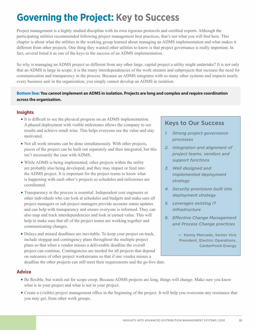
INSIGHTS INTO ADVANCED DISTRIBUTION MANAGEMENT SYSTEMS | DOE 35
Governing the Project: Key to SuccessProject management is a highly studied discipline with its own rigorous protocols and certifi ed experts. Although the participating utilities recommended following project management best practices, that’s not what you will fi nd here. This chapter is about what the utilities in the working group learned about managing an ADMS implementation and what makes it different from other projects. One thing they wanted other utilities to know is that project governance is really important. In fact, several listed it as one of the keys to the success of an ADMS implementation.
So why is managing an ADMS project so different from any other large, capital project a utility might undertake? It is not only that an ADMS is large in scope; it is the many interdependencies of the work streams and subprojects that increase the need for communication and transparency in the process. Because an ADMS integrates with so many other systems and impacts nearly every business unit in the organization, you simply cannot develop an ADMS in isolation.
Bottom line: You cannot implement an ADMS in isolation. Projects are long and complex and require coordination across the organization.
Insights · It is diffi cult to see the physical progress on an ADMS implementation. A phased deployment with visible milestones allows the company to see results and achieve small wins. This helps everyone see the value and stay motivated.
· Not all work streams can be done simultaneously. With other projects, pieces of the project can be built out separately and then integrated, but this isn’t necessarily the case with ADMS.
· While ADMS is being implemented, other projects within the utility are probably also being developed, and they may impact or feed into the ADMS project. It is important for the project teams to know what is happening with each other’s projects so schedules and milestones are coordinated.
· Transparency in the process is essential. Independent cost engineers or other individuals who can look at schedules and budgets and make sure all project managers or sub project managers provide accurate status updates and can help with transparency and ensure everyone is informed. They can also map and track interdependencies and look at earned value. This will help to make sure that all of the project teams are working together and communicating changes.
· Delays and missed deadlines are inevitable. To keep your project on track, include stopgap and contingency plans throughout the multiple project plans so that when a vendor misses a deliverable deadline the overall project can continue. Contingencies are needed for all projects that depend on outcomes of other project workstreams so that if one vendor misses a deadline the other projects can still meet their requirements and the go-live date.
Advice
· Be fl exible, but watch out for scope creep. Because ADMS projects are long, things will change. Make sure you know what is in your project and what is not in your project.
· Create a (visible) project management offi ce in the beginning of the project. It will help you overcome any resistance that you may get, from other work groups.
Keys to Our Success
1. Strong project governance processes
2. Integration and alignment of project teams, vendors and support functions
3. Well designed and implemented deployment strategy
4. Security provisions built into deployment strategy
5. Leverages existing IT infrastructure
6. E� ective Change Management and Process Change practices
— Kenny Mercado, Senior Vice President, Electric Operations,
CenterPoint Energy
Voices of Experience | Advanced Distribution Management Systems_brochure.indd 35 2/11/15 12:52 PM

INSIGHTS INTO ADVANCED DISTRIBUTION MANAGEMENT SYSTEMS | DOE36
· Develop an integrated loaded schedule that includes all of the projects (and sub projects) that might impact or be impacted by the ADMS project. Mapping project interdependencies is critical.
· Consider adding a cost engineer—independent from the project—who asks a lot of questions and challenges project costs.
· Have an independent person in the project management offi ce track the schedules and ping the project managers weekly for status and schedule changes. This can help to show earned value (the value achieved as interlinked projects are completed and new functionalities are available).
· Consider creating a team dedicated to ADMS rather than asking people to work on it part time while also operating the grid. The project requires the team’s full attention.
· Establish a team that cuts across all departments and involves individuals in the departments that will be impacted by the new system. And make sure you have someone from the department that will be responsible for supporting the system when it is live. Physically locate the core team together. Colocation will help break down silos.
· Develop a strategy for recruiting good people to join the project team. ADMS is a long-term project, and personnel might be reluctant to leave their current job for fear that they won’t have a job to return to when the project ends. The strategy should include a plan for either keeping positions open for the project team or the transitions to a new positions or departments.
· Find people in your organization who have the interest and drive to learn the ADMS. (This might be more important that having a strong skill set match.)
· Employees working on the EMS/transmission operations have skills that are also needed with for ADMS. Think about leveraging their knowledge as well.
· Make sure to confi rm that staff will be available when needed—or are dedicated full time to the project. It will be critical for making sure that the right people are in meetings and that their perspectives are heard and incorporated.
· Understand that the project will need a strong OT/IT partnership, because even though it is an operational tool, the systems are owned by IT.
· Form a high-level steering committee to provide consistent direction across your organization and to help break down the functional silos that may exist in your utility. The Smart Grid Steering Committee at one smaller utility consists of the CEO, CIO, CFO, chief legal counsel, and chief customer offi cer. At a larger utility, it may include a crosscut of directors or senior vice presidents.
· Actively involve HR from the beginning. It’s better to work with them up front rather than telling them later, “Hey, we want you to do this for us.” HR can help make sure there will be a job for project team members when the project ends—and help develop strategies for this.
· Think about utilizing contractors. Utilities that hadn’t done this type of project found it helpful to leverage their knowledge, and they suggested having a balance between contractors and full-time employees.
· Set up weekly meetings to review the various project schedules and milestones and talk about any delays or challenges that might have arisen. Weekly meetings can provide transparency to the process and help mitigate risks by exposing problems and discussing how to resolve them.
· Include vendors in project management status meetings. Mandate this in the contract. They might push back at fi rst, but utilities reported that there is tremendous value in having the vendors at the table when discussing delays or project impacts so they can provide answers fi rsthand and help develop solutions.
Voices of Experience | Advanced Distribution Management Systems_brochure.indd 36 2/11/15 12:52 PM

INSIGHTS INTO ADVANCED DISTRIBUTION MANAGEMENT SYSTEMS | DOE 37
Looking Back—What We Learned
Managing a Technology Project
IT projects are different from capital projects such as building or upgrading power plants. With power plant projects or distribution projects, it is possible to see stuff being built, to see foundations going in, structures going up, wires being pulled, and all that. It is possible to visually see the stages of the project. An ADMS project is not like that. Although both can be long, it is diffi cult to see progress during an ADMS project. For example, there is a testing phase, which will fi nd defects. But what is a defect? This is kind of a nebulous, weird thing—it’s the lack of something working, and it’s really hard to measure. You don’t know how many you’re going to have and you don’t know how many will get fi xed or how long it will take. Theoretically they all need to be fi xed, but in reality they’re not all going to be fi xed. So you have to rank them and decide where to focus your resources.
Project Control
Project controls staff actually came from the generation construction side of the company and came over and helped us build the project controls discipline, which included having independent people challenge our costs and update the schedule. They would ping all the project managers and the sub project managers to get their status on a weekly basis and the overall project manager and program offi ce could then see an actual versus planned schedule update. The other thing that they did that I thought was critically important in this project was to create an integrated schedule. They mapped the inter-dependencies and they tracked at “earned value.” Originally we had four different tracks on our ADMS project, and they all had their independent schedules. Each one was running their project on their schedule and they were listening to each other, but what they hadn’t thought about was integration: my substation work in this area completed at the same time as your circuit work so that if the technology component was completed and available to control the circuits/substation I would have “earned a value” because I could deliver benefi ts by being able to execute the function in this area. Without the integrated schedule, there was no way to ensure that any of the capabilities would have been delivered until the very end of the project, so all the “earned value” would have been delayed until the end of the project.
Building a Team
I can tell you it was a struggle, but I would say we didn’t know what we didn’t know. I mean that’s the reality. We tried really hard…we brought in operators, we brought in engineers, but we probably didn’t bring in enough people to participate on the project at the start, and that’s probably what I would have done a little bit differently.
Voices of Experience | Advanced Distribution Management Systems_brochure.indd 37 2/11/15 12:52 PM

INSIGHTS INTO ADVANCED DISTRIBUTION MANAGEMENT SYSTEMS | DOE38
What We Did—Leadership Internships
CenterPoint Energy developed a leadership development intern program. Although the customer manger was dedicated to the ADMS project team, an intern fi lled their job on a rotational basis. HR helped to develop the program. The intern program gave the individual pulled onto the project team the confi dence to go to the project team without the fear of not having a job when the project was done. It gave the intern new leadership exposure/development.
What We Did—Weekly Meetings
Every Thursday morning at 9:00, we go through every work stream, all the specifi c milestones, and everything that changed from the week before—any pluses or minuses or completions—and we have integrated views of all of the various project plans. We do this so everybody’s in the same room together talking about their aspect of the project, and everyone can ask questions, and fi nd out how their project might be impacted. Everybody is involved in that simultaneously. This provides a lot of transparency.
Voices of Experience | Advanced Distribution Management Systems_brochure.indd 38 2/11/15 12:52 PM
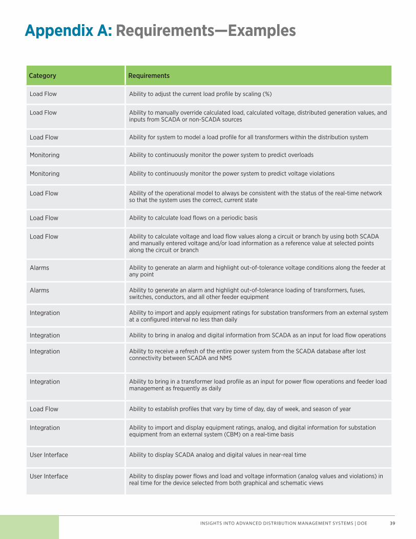
INSIGHTS INTO ADVANCED DISTRIBUTION MANAGEMENT SYSTEMS | DOE 39
Appendix A: Requirements—Examples
Category Requirements
Load Flow Ability to adjust the current load profi le by scaling (%)
Load Flow Ability to manually override calculated load, calculated voltage, distributed generation values, and inputs from SCADA or non-SCADA sources
Load Flow Ability for system to model a load profi le for all transformers within the distribution system
Monitoring Ability to continuously monitor the power system to predict overloads
Monitoring Ability to continuously monitor the power system to predict voltage violations
Load Flow Ability of the operational model to always be consistent with the status of the real-time network so that the system uses the correct, current state
Load Flow Ability to calculate load fl ows on a periodic basis
Load Flow Ability to calculate voltage and load fl ow values along a circuit or branch by using both SCADA and manually entered voltage and/or load information as a reference value at selected points along the circuit or branch
Alarms Ability to generate an alarm and highlight out-of-tolerance voltage conditions along the feeder at any point
Alarms Ability to generate an alarm and highlight out-of-tolerance loading of transformers, fuses, switches, conductors, and all other feeder equipment
Integration Ability to import and apply equipment ratings for substation transformers from an external system at a confi gured interval no less than daily
Integration Ability to bring in analog and digital information from SCADA as an input for load fl ow operations
Integration Ability to receive a refresh of the entire power system from the SCADA database after lost connectivity between SCADA and NMS
Integration Ability to bring in a transformer load profi le as an input for power fl ow operations and feeder load management as frequently as daily
Load Flow Ability to establish profi les that vary by time of day, day of week, and season of year
Integration Ability to import and display equipment ratings, analog, and digital information for substation equipment from an external system (CBM) on a real-time basis
User Interface Ability to display SCADA analog and digital values in near-real time
User Interface Ability to display power fl ows and load and voltage information (analog values and violations) in real time for the device selected from both graphical and schematic views
Voices of Experience | Advanced Distribution Management Systems_brochure.indd 39 2/11/15 12:52 PM
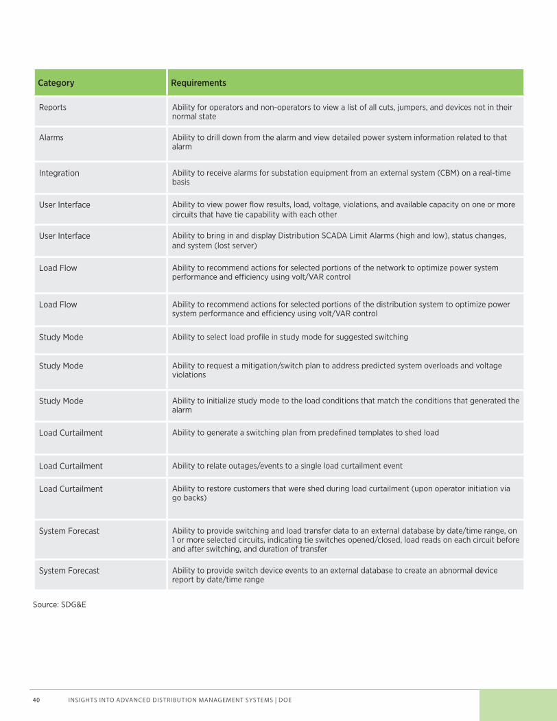
INSIGHTS INTO ADVANCED DISTRIBUTION MANAGEMENT SYSTEMS | DOE40
Category Requirements
Reports Ability for operators and non-operators to view a list of all cuts, jumpers, and devices not in their normal state
Alarms Ability to drill down from the alarm and view detailed power system information related to that alarm
Integration Ability to receive alarms for substation equipment from an external system (CBM) on a real-time basis
User Interface Ability to view power fl ow results, load, voltage, violations, and available capacity on one or more circuits that have tie capability with each other
User Interface Ability to bring in and display Distribution SCADA Limit Alarms (high and low), status changes, and system (lost server)
Load Flow Ability to recommend actions for selected portions of the network to optimize power system performance and e� ciency using volt/VAR control
Load Flow Ability to recommend actions for selected portions of the distribution system to optimize power system performance and e� ciency using volt/VAR control
Study Mode Ability to select load profi le in study mode for suggested switching
Study Mode Ability to request a mitigation/switch plan to address predicted system overloads and voltage violations
Study Mode Ability to initialize study mode to the load conditions that match the conditions that generated the alarm
Load Curtailment Ability to generate a switching plan from predefi ned templates to shed load
Load Curtailment Ability to relate outages/events to a single load curtailment event
Load Curtailment Ability to restore customers that were shed during load curtailment (upon operator initiation via go backs)
System Forecast Ability to provide switching and load transfer data to an external database by date/time range, on 1 or more selected circuits, indicating tie switches opened/closed, load reads on each circuit before and after switching, and duration of transfer
System Forecast Ability to provide switch device events to an external database to create an abnormal device report by date/time range
Source: SDG&E
Voices of Experience | Advanced Distribution Management Systems_brochure.indd 40 2/11/15 12:52 PM

INSIGHTS INTO ADVANCED DISTRIBUTION MANAGEMENT SYSTEMS | DOE 41
Appendix B: Distribution System Inventory
REQUIREMENTS
FOR A DISTRIBUTION
SYSTEM INVENTORY AND
CONDITION ASSESSMENT
November 2, 2006
Voices of Experience | Advanced Distribution Management Systems_brochure.indd 41 2/11/15 12:52 PM

INSIGHTS INTO ADVANCED DISTRIBUTION MANAGEMENT SYSTEMS | DOE42
UTILITY DSIA RFP 1 11/02/2006
1. DSIA Requirements 1.1 Project Scope
The DSIA project is focused on the overhead electric distribution system. This project will encompass approximately 600 circuits consisting of approximately 275,000 poles within a 4,700 square mile service area. This project is to be completed on urban and rural circuits with 12.47kV, 13.2kV, and 34.5 kV voltages.
1.1.1 DSIA Inventory Overview As UTILITY already has had a fully functional GIS system for a number of years, the inventory component of the DSIA project would be better characterized as verification and correction project instead of a traditional facility inventory that is primarily new data capture. Facilities to be inventoried include all overhead UTILITY facilities beginning with the first pole of a circuit outside of the serving substation fence up to and including the service conductors and in some cases the meter. The requirements of the DSIA inventory will be specified in detail in later sections, but in general this portion of the project will validate and correct: • Facility/feature existence • Location correctness • Electrical connectivity • Facility attribute verification • Pole Age
1.1.2 DSIA Asset Condition Assessment Overview The asset condition assessment component of the DSIA project will identify significant existing mechanical, electrical, and environmental conditions in the field that should be corrected in the near future. Again, facilities to be assessed include all overhead facilities beginning with the first pole of a circuit outside of the serving substation fence up to and including the service conductors and in some cases the meter. The requirements of the DSIA condition assessment will be specified in detail later but in general this portion of the project will identify the assessment conditions and classify then according to the following priorities: • 0 – Critical (needs immediate repair • 1 – Urgent (needs repair <6mo) • 2 – Seasonal (needs repair <2yr) • 3 – Routine (needs repair >2yr) • 4 – Non-Std (needs changed sometime)
The term "condition assessment" refers to collection of field data to be used in evaluating various Asset Management strategies and to assess the overall "health" of the distribution system. UTILITY plans to make repairs to conditions classified as Critical and Urgent as Corrective Maintenance. Other conditions are considered Elective Maintenance and will be evaluated as part of various programmatic approaches and possibly tracked for trending purposes. Elective Maintenance conditions may or may not be repaired based solely on the conditions own merits.
Voices of Experience | Advanced Distribution Management Systems_brochure.indd 42 2/11/15 12:52 PM
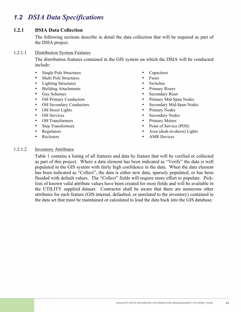
INSIGHTS INTO ADVANCED DISTRIBUTION MANAGEMENT SYSTEMS | DOE 43
UTILITY DSIA RFP 2 11/02/2006
1.2 DSIA Data Specifications
1.2.1 DSIA Data Collection The following sections describe in detail the data collection that will be required as part of the DSIA project.
1.2.1.1 Distribution System Features The distribution features contained in the GIS system on which the DSIA will be conducted include: • Single Pole Structures • Multi Pole Structures • Lighting Structures • Building Attachments • Guy Schemes • OH Primary Conductors • OH Secondary Conductors • OH Street Lights • OH Services • OH Transformers • Step Transformers • Regulators • Reclosers
• Capacitors • Fuses • Switches • Primary Risers • Secondary Riser • Primary Mid-Span Nodes • Secondary Mid-Span Nodes • Primary Nodes • Secondary Nodes • Primary Meters • Point of Service (POS) • Area (dusk-to-dawn) Lights • AMR Devices
1.2.1.2 Inventory Attributes Table 1 contains a listing of all features and data by feature that will be verified or collected as part of this project. Where a data element has been indicated as “Verify” the data is well populated in the GIS system with fairly high confidence in the data. When the data element has been indicated as “Collect”, the data is either new data, sparsely populated, or has been flooded with default values. The “Collect” fields will require more effort to populate. Pick-lists of known valid attribute values have been created for most fields and will be available in the UTILITY supplied dataset. Contractor shall be aware that there are numerous other attributes for each feature (GIS internal, defaulted, or unrelated to the inventory) contained in the data set that must be maintained or calculated to load the data back into the GIS database.
Voices of Experience | Advanced Distribution Management Systems_brochure.indd 43 2/11/15 12:52 PM
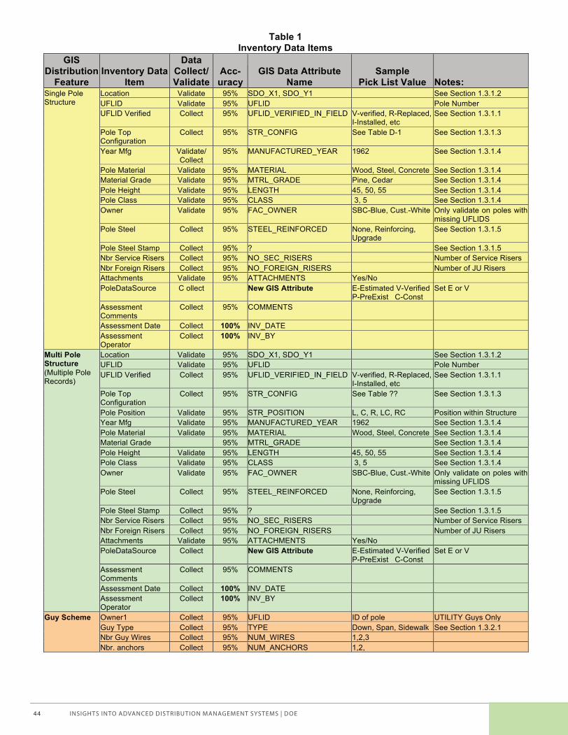
INSIGHTS INTO ADVANCED DISTRIBUTION MANAGEMENT SYSTEMS | DOE44
UTILITY DSIA RFP 3 11/02/2006
Table 1 Inventory Data Items
GIS Distribution
Feature Inventory Data
Item
Data Collect/ Validate
Acc-uracy
GIS Data Attribute Name
Sample Pick List Value Notes:
Single Pole Structure
Location Validate 95% SDO_X1, SDO_Y1 See Section 1.3.1.2 UFLID Validate 95% UFLID Pole Number UFLID Verified Collect 95% UFLID_VERIFIED_IN_FIELD V-verified, R-Replaced,
I-Installed, etc See Section 1.3.1.1
Pole Top Configuration
Collect 95% STR_CONFIG See Table D-1 See Section 1.3.1.3
Year Mfg Validate/ Collect
95% MANUFACTURED_YEAR 1962 See Section 1.3.1.4
Pole Material Validate 95% MATERIAL Wood, Steel, Concrete See Section 1.3.1.4 Material Grade Validate 95% MTRL_GRADE Pine, Cedar See Section 1.3.1.4 Pole Height Validate 95% LENGTH 45, 50, 55 See Section 1.3.1.4 Pole Class Validate 95% CLASS 3, 5 See Section 1.3.1.4 Owner Validate 95% FAC_OWNER SBC-Blue, Cust.-White Only validate on poles with
missing UFLIDS Pole Steel Collect 95% STEEL_REINFORCED None, Reinforcing,
Upgrade See Section 1.3.1.5
Pole Steel Stamp Collect 95% ? See Section 1.3.1.5 Nbr Service Risers Collect 95% NO_SEC_RISERS Number of Service Risers Nbr Foreign Risers Collect 95% NO_FOREIGN_RISERS Number of JU Risers Attachments Validate 95% ATTACHMENTS Yes/No PoleDataSource C ollect New GIS Attribute E-Estimated V-Verified
P-PreExist C-Const Set E or V
Assessment Comments
Collect 95% COMMENTS
Assessment Date Collect 100% INV_DATE Assessment Operator
Collect 100% INV_BY
Multi Pole Structure (Multiple Pole Records)
Location Validate 95% SDO_X1, SDO_Y1 See Section 1.3.1.2 UFLID Validate 95% UFLID Pole Number UFLID Verified Collect 95% UFLID_VERIFIED_IN_FIELD V-verified, R-Replaced,
I-Installed, etc See Section 1.3.1.1
Pole Top Configuration
Collect 95% STR_CONFIG See Table ?? See Section 1.3.1.3
Pole Position Validate 95% STR_POSITION L, C, R, LC, RC Position within Structure Year Mfg Validate 95% MANUFACTURED_YEAR 1962 See Section 1.3.1.4 Pole Material Validate 95% MATERIAL Wood, Steel, Concrete See Section 1.3.1.4 Material Grade 95% MTRL_GRADE See Section 1.3.1.4 Pole Height Validate 95% LENGTH 45, 50, 55 See Section 1.3.1.4 Pole Class Validate 95% CLASS 3, 5 See Section 1.3.1.4 Owner Validate 95% FAC_OWNER SBC-Blue, Cust.-White Only validate on poles with
missing UFLIDS Pole Steel Collect 95% STEEL_REINFORCED None, Reinforcing,
Upgrade See Section 1.3.1.5
Pole Steel Stamp Collect 95% ? See Section 1.3.1.5 Nbr Service Risers Collect 95% NO_SEC_RISERS Number of Service Risers Nbr Foreign Risers Collect 95% NO_FOREIGN_RISERS Number of JU Risers Attachments Validate 95% ATTACHMENTS Yes/No PoleDataSource Collect New GIS Attribute E-Estimated V-Verified
P-PreExist C-Const Set E or V
Assessment Comments
Collect 95% COMMENTS
Assessment Date Collect 100% INV_DATE Assessment Operator
Collect 100% INV_BY
Guy Scheme Owner1 Collect 95% UFLID ID of pole UTILITY Guys Only Guy Type Collect 95% TYPE Down, Span, Sidewalk See Section 1.3.2.1 Nbr Guy Wires Collect 95% NUM_WIRES 1,2,3 Nbr. anchors Collect 95% NUM_ANCHORS 1,2,
Voices of Experience | Advanced Distribution Management Systems_brochure.indd 44 2/11/15 12:52 PM
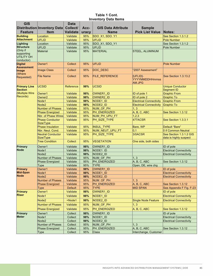
INSIGHTS INTO ADVANCED DISTRIBUTION MANAGEMENT SYSTEMS | DOE 45
UTILITY DSIA RFP 4 11/02/2006
Table 1 Cont. Inventory Data Items
GIS Distribution
Feature Inventory Data
Item
Data Collect/ Validate
Acc-uracy
GIS Data Attribute Name
Sample Pick List Value Notes:
Building Attachment
Location Validate 95% SDO_X1, SDO_Y1 See Section 1.3.1.2 UFLID Validate 95% UFLID Pole Number
Lighting Structure (Only if supporting UTILITY OH conductor)
Location Validate 95% SDO_X1, SDO_Y1 See Section 1.3.1.2 UFLID Validate 95% UFLID Pole Number Material Validate 95% MATERIAL STEEL, ALUMINUM
Digital Assessment Image (Where Requested)
Owner1 Collect 95% UFLID Pole Number
Image Class Collect 95% DOC_DESC “2007 Assessment”
File Name Collect 95% FILE_REFERENCE [UFLID]-YYYYMMDDHHmmssAM.JPG
See Section 1.3.13.2
Primary Line Section (Multiple Wire Records)
UCSID Reference 98% UCSID Unique Conductor Segment ID
Owner1 Validate 98% OWNER1_ID ID of pole 1 Graphic From Owner2 Validate 98% OWNER2_ID ID of pole 2 Graphic To Node1 Validate 98% NODE1_ID Electrical Connectivity Graphic From Node2 Validate 98% NODE2_ID Electrical Connectivity Graphic To Number of Phases Validate 95% NUM_OF_PH 1, 3 Phase Energized Validate 95% PH_ENERGIZED A, B, C, ABC See Section 1.3.12 Nbr. of Phase Wires Validate 95% NUM_PH_UPU_FT 1,2,3 Phase Conductor Size/Type
Validate 95% PH_SIZE_TYPE 477ACSR See Section 1.3.3.1
Phase Insulation Validate 95% INSUL_TYPE Bare, WP Default “Bare” Nbr. Neut. Cond. Validate 95% NUM_NEUT_UPU_FT 0,1 0 if Common Neutral Neutral Conductor Size/Type
Validate 95% PH_SIZE_TYPE 3/0ACSR See Section 1.3.1.2 GIS data is highly suspect
Tree Condition Collect 95% VEGETATION One side, both sides
Primary Node
Owner1 Validate 98% OWNER1_ID ID of pole Node1 Validate 98% NODE1_ID Electrical Connectivity Node2 Validate 98% NODE2_ID Electrical Connectivity Number of Phases Validate 95% NUM_OF_PH 1, 3 Phase Energized Validate 95% PH_ENERGIZED A, B, C, ABC See Section 1.3.12 Type Validate 95% TYPE Open, DE, wire chg
Primary Mid-Span Node
Owner1 Validate 98% OWNER1_ID ID of pole Node1 Validate 98% NODE1_ID Electrical Connectivity Node2 Validate 98% NODE2_ID Electrical Connectivity Number of Phases Validate 95% NUM_OF_PH 1, 3 Phase Energized Validate 95% PH_ENERGIZED A, B, C, ABC See Section 1.3.12 Type Default 95% TYPE MID SPAN See Appendix F Fig. F-23
Primary Riser
Owner1 Validate 98% OWNER1_ID ID of pole Node1 Validate 98% NODE1_ID Electrical Connectivity Node2 =Node1 98% NODE2_ID Single Node Feature Electrical Connectivity Number of Phases Validate 95% NUM_OF_PH 1, 3 Phase Energized Validate 95% PH_ENERGIZED A, B, C, ABC See Section 1.3.12
Primary Meter
Owner1 Collect 98% OWNER1_ID ID of pole Node1 Collect 98% NODE1_ID Electrical Connectivity Node2 Collect 98% NODE2_ID Electrical Connectivity Number of Phases Collect 95% NUM_OF_PH 1, 3 Phase Energized Collect 95% PH_ENERGIZED A, B, C, ABC See Section 1.3.12 Type Collect 95% Class Interchange, Customer
Voices of Experience | Advanced Distribution Management Systems_brochure.indd 45 2/11/15 12:52 PM
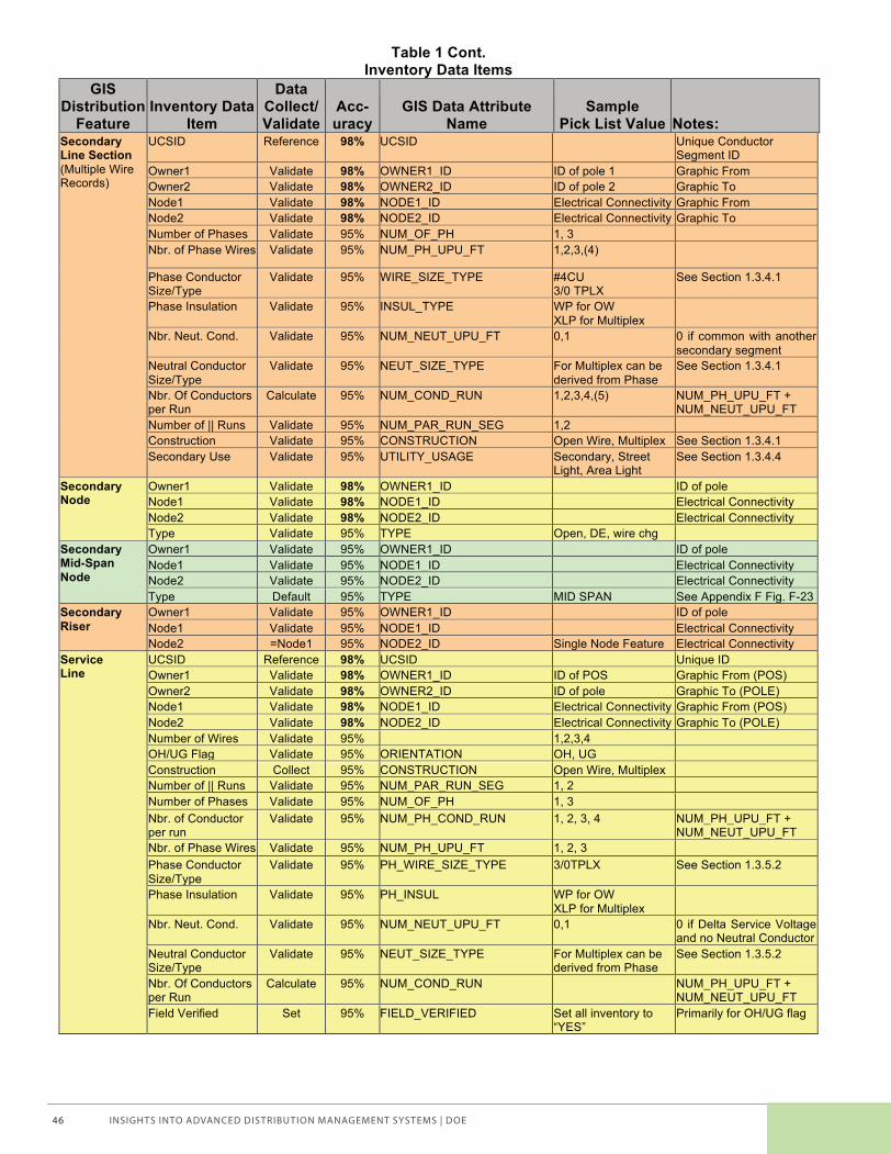
INSIGHTS INTO ADVANCED DISTRIBUTION MANAGEMENT SYSTEMS | DOE46
UTILITY DSIA RFP 5 11/02/2006
Table 1 Cont. Inventory Data Items
GIS Distribution
Feature Inventory Data
Item
Data Collect/ Validate
Acc-uracy
GIS Data Attribute Name
Sample Pick List Value Notes:
Secondary Line Section (Multiple Wire Records)
UCSID Reference 98% UCSID Unique Conductor Segment ID
Owner1 Validate 98% OWNER1_ID ID of pole 1 Graphic From Owner2 Validate 98% OWNER2_ID ID of pole 2 Graphic To Node1 Validate 98% NODE1_ID Electrical Connectivity Graphic From Node2 Validate 98% NODE2_ID Electrical Connectivity Graphic To Number of Phases Validate 95% NUM_OF_PH 1, 3 Nbr. of Phase Wires Validate 95% NUM_PH_UPU_FT 1,2,3,(4)
Phase Conductor Size/Type
Validate 95% WIRE_SIZE_TYPE #4CU 3/0 TPLX
See Section 1.3.4.1
Phase Insulation Validate 95% INSUL_TYPE WP for OW XLP for Multiplex
Nbr. Neut. Cond. Validate 95% NUM_NEUT_UPU_FT 0,1 0 if common with another secondary segment
Neutral Conductor Size/Type
Validate 95% NEUT_SIZE_TYPE For Multiplex can be derived from Phase
See Section 1.3.4.1
Nbr. Of Conductors per Run
Calculate 95% NUM_COND_RUN 1,2,3,4,(5) NUM_PH_UPU_FT + NUM_NEUT_UPU_FT
Number of || Runs Validate 95% NUM_PAR_RUN_SEG 1,2 Construction Validate 95% CONSTRUCTION Open Wire, Multiplex See Section 1.3.4.1 Secondary Use Validate 95% UTILITY_USAGE Secondary, Street
Light, Area Light See Section 1.3.4.4
Secondary Node
Owner1 Validate 98% OWNER1_ID ID of pole Node1 Validate 98% NODE1_ID Electrical Connectivity Node2 Validate 98% NODE2_ID Electrical Connectivity Type Validate 95% TYPE Open, DE, wire chg
Secondary Mid-Span Node
Owner1 Validate 95% OWNER1_ID ID of pole Node1 Validate 95% NODE1_ID Electrical Connectivity Node2 Validate 95% NODE2_ID Electrical Connectivity Type Default 95% TYPE MID SPAN See Appendix F Fig. F-23
Secondary Riser
Owner1 Validate 95% OWNER1_ID ID of pole Node1 Validate 95% NODE1_ID Electrical Connectivity Node2 =Node1 95% NODE2_ID Single Node Feature Electrical Connectivity
Service Line
UCSID Reference 98% UCSID Unique ID Owner1 Validate 98% OWNER1_ID ID of POS Graphic From (POS) Owner2 Validate 98% OWNER2_ID ID of pole Graphic To (POLE) Node1 Validate 98% NODE1_ID Electrical Connectivity Graphic From (POS) Node2 Validate 98% NODE2_ID Electrical Connectivity Graphic To (POLE) Number of Wires Validate 95% 1,2,3,4 OH/UG Flag Validate 95% ORIENTATION OH, UG Construction Collect 95% CONSTRUCTION Open Wire, Multiplex Number of || Runs Validate 95% NUM_PAR_RUN_SEG 1, 2 Number of Phases Validate 95% NUM_OF_PH 1, 3 Nbr. of Conductor per run
Validate 95% NUM_PH_COND_RUN 1, 2, 3, 4 NUM_PH_UPU_FT + NUM_NEUT_UPU_FT
Nbr. of Phase Wires Validate 95% NUM_PH_UPU_FT 1, 2, 3 Phase Conductor Size/Type
Validate 95% PH_WIRE_SIZE_TYPE 3/0TPLX See Section 1.3.5.2
Phase Insulation Validate 95% PH_INSUL WP for OW XLP for Multiplex
Nbr. Neut. Cond. Validate 95% NUM_NEUT_UPU_FT 0,1 0 if Delta Service Voltage and no Neutral Conductor
Neutral Conductor Size/Type
Validate 95% NEUT_SIZE_TYPE For Multiplex can be derived from Phase
See Section 1.3.5.2
Nbr. Of Conductors per Run
Calculate 95% NUM_COND_RUN NUM_PH_UPU_FT + NUM_NEUT_UPU_FT
Field Verified Set 95% FIELD_VERIFIED Set all inventory to “YES”
Primarily for OH/UG flag
Voices of Experience | Advanced Distribution Management Systems_brochure.indd 46 2/11/15 12:52 PM
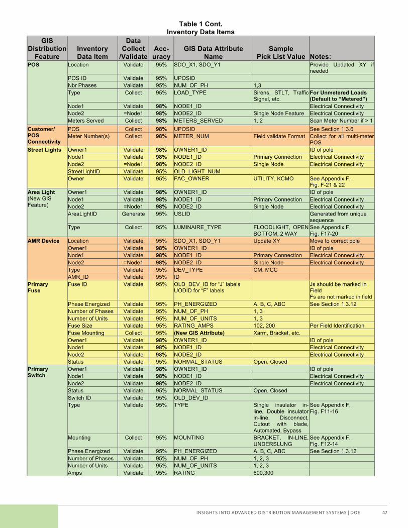
INSIGHTS INTO ADVANCED DISTRIBUTION MANAGEMENT SYSTEMS | DOE 47
UTILITY DSIA RFP 6 11/02/2006
Table 1 Cont. Inventory Data Items
GIS Distribution
Feature Inventory Data Item
Data Collect
/Validate Acc-uracy
GIS Data Attribute Name
Sample Pick List Value Notes:
POS
Location Validate 95% SDO_X1, SDO_Y1 Provide Updated XY if needed
POS ID Validate 95% UPOSID Nbr Phases Validate 95% NUM_OF_PH 1,3 Type Collect 95% LOAD_TYPE Sirens, STLT, Traffic
Signal, etc. For Unmetered Loads (Default to “Metered”)
Node1 Validate 98% NODE1_ID Electrical Connectivity Node2 =Node1 98% NODE2_ID Single Node Feature Electrical Connectivity Meters Served Collect 98% METERS_SERVED 1, 2 Scan Meter Number if > 1
Customer/ POS Connectivity
POS Collect 98% UPOSID See Section 1.3.6 Meter Number(s) Collect 98% METER_NUM Field validate Format Collect for all multi-meter
POS Street Lights Owner1 Validate 98% OWNER1_ID ID of pole
Node1 Validate 98% NODE1_ID Primary Connection Electrical Connectivity Node2 =Node1 98% NODE2_ID Single Node Electrical Connectivity StreetLightID Validate 95% OLD_LIGHT_NUM Owner Validate 95% FAC_OWNER UTILITY, KCMO See Appendix F,
Fig. F-21 & 22 Area Light (New GIS Feature)
Owner1 Validate 98% OWNER1_ID ID of pole Node1 Validate 98% NODE1_ID Primary Connection Electrical Connectivity Node2 =Node1 98% NODE2_ID Single Node Electrical Connectivity AreaLightID Generate 95% USLID Generated from unique
sequence Type Collect 95% LUMINAIRE_TYPE FLOODLIGHT, OPEN
BOTTOM, 2 WAY See Appendix F, Fig. F17-20
AMR Device Location Validate 95% SDO_X1, SDO_Y1 Update XY Move to correct pole Owner1 Validate 98% OWNER1_ID ID of pole Node1 Validate 98% NODE1_ID Primary Connection Electrical Connectivity Node2 =Node1 98% NODE2_ID Single Node Electrical Connectivity Type Validate 95% DEV_TYPE CM, MCC AMR_ID Validate 95% ID
Primary Fuse
Fuse ID Validate 95% OLD_DEV_ID for “J” labels UODID for “F” labels
Js should be marked in Field Fs are not marked in field
Phase Energized Validate 95% PH_ENERGIZED A, B, C, ABC See Section 1.3.12 Number of Phases Validate 95% NUM_OF_PH 1, 3 Number of Units Validate 95% NUM_OF_UNITS 1, 3 Fuse Size Validate 95% RATING_AMPS 102, 200 Per Field Identification Fuse Mounting Collect 95% (New GIS Attribute) Xarm, Bracket, etc. Owner1 Validate 98% OWNER1_ID ID of pole Node1 Validate 98% NODE1_ID Electrical Connectivity Node2 Validate 98% NODE2_ID Electrical Connectivity Status Validate 95% NORMAL_STATUS Open, Closed
Primary Switch
Owner1 Validate 98% OWNER1_ID ID of pole Node1 Validate 98% NODE1_ID Electrical Connectivity Node2 Validate 98% NODE2_ID Electrical Connectivity Status Validate 95% NORMAL_STATUS Open, Closed Switch ID Validate 95% OLD_DEV_ID Type Validate 95% TYPE Single insulator in-
line, Double insulator in-line, Disconnect, Cutout with blade, Automated, Bypass
See Appendix F, Fig. F11-16
Mounting Collect 95% MOUNTING BRACKET, IN-LINE, UNDERSLUNG
See Appendix F, Fig. F12-14
Phase Energized Validate 95% PH_ENERGIZED A, B, C, ABC See Section 1.3.12 Number of Phases Validate 95% NUM_OF_PH 1, 2, 3 Number of Units Validate 95% NUM_OF_UNITS 1, 2, 3 Amps Validate 95% RATING 600,300
Voices of Experience | Advanced Distribution Management Systems_brochure.indd 47 2/11/15 12:52 PM
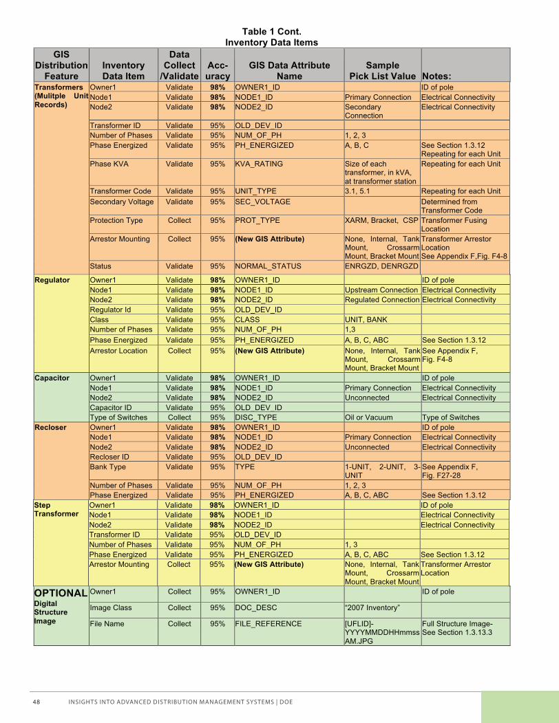
INSIGHTS INTO ADVANCED DISTRIBUTION MANAGEMENT SYSTEMS | DOE48
UTILITY DSIA RFP 7 11/02/2006
Table 1 Cont. Inventory Data Items
GIS Distribution
Feature Inventory Data Item
Data Collect
/Validate Acc-uracy
GIS Data Attribute Name
Sample Pick List Value Notes:
Transformers (Mulitple Unit Records)
Owner1 Validate 98% OWNER1_ID ID of pole Node1 Validate 98% NODE1_ID Primary Connection Electrical Connectivity Node2 Validate 98% NODE2_ID Secondary
Connection Electrical Connectivity
Transformer ID Validate 95% OLD_DEV_ID Number of Phases Validate 95% NUM_OF_PH 1, 2, 3 Phase Energized Validate 95% PH_ENERGIZED A, B, C See Section 1.3.12
Repeating for each Unit Phase KVA Validate 95% KVA_RATING Size of each
transformer, in kVA, at transformer station
Repeating for each Unit
Transformer Code Validate 95% UNIT_TYPE 3.1, 5.1 Repeating for each Unit Secondary Voltage Validate 95% SEC_VOLTAGE Determined from
Transformer Code Protection Type Collect 95% PROT_TYPE XARM, Bracket, CSP Transformer Fusing
Location Arrestor Mounting Collect 95% (New GIS Attribute) None, Internal, Tank
Mount, Crossarm Mount, Bracket Mount
Transformer Arrestor Location See Appendix F,Fig. F4-8
Status Validate 95% NORMAL_STATUS ENRGZD, DENRGZD
Regulator Owner1 Validate 98% OWNER1_ID ID of pole Node1 Validate 98% NODE1_ID Upstream Connection Electrical Connectivity Node2 Validate 98% NODE2_ID Regulated Connection Electrical Connectivity Regulator Id Validate 95% OLD_DEV_ID Class Validate 95% CLASS UNIT, BANK Number of Phases Validate 95% NUM_OF_PH 1,3 Phase Energized Validate 95% PH_ENERGIZED A, B, C, ABC See Section 1.3.12 Arrestor Location Collect 95% (New GIS Attribute) None, Internal, Tank
Mount, Crossarm Mount, Bracket Mount
See Appendix F, Fig. F4-8
Capacitor Owner1 Validate 98% OWNER1_ID ID of pole Node1 Validate 98% NODE1_ID Primary Connection Electrical Connectivity Node2 Validate 98% NODE2_ID Unconnected Electrical Connectivity Capacitor ID Validate 95% OLD_DEV_ID Type of Switches Collect 95% DISC_TYPE Oil or Vacuum Type of Switches
Recloser Owner1 Validate 98% OWNER1_ID ID of pole Node1 Validate 98% NODE1_ID Primary Connection Electrical Connectivity Node2 Validate 98% NODE2_ID Unconnected Electrical Connectivity Recloser ID Validate 95% OLD_DEV_ID Bank Type Validate 95% TYPE 1-UNIT, 2-UNIT, 3-
UNIT See Appendix F, Fig. F27-28
Number of Phases Validate 95% NUM_OF_PH 1, 2, 3 Phase Energized Validate 95% PH_ENERGIZED A, B, C, ABC See Section 1.3.12
Step Transformer
Owner1 Validate 98% OWNER1_ID ID of pole Node1 Validate 98% NODE1_ID Electrical Connectivity Node2 Validate 98% NODE2_ID Electrical Connectivity Transformer ID Validate 95% OLD_DEV_ID Number of Phases Validate 95% NUM_OF_PH 1, 3 Phase Energized Validate 95% PH_ENERGIZED A, B, C, ABC See Section 1.3.12 Arrestor Mounting Collect 95% (New GIS Attribute) None, Internal, Tank
Mount, Crossarm Mount, Bracket Mount
Transformer Arrestor Location
OPTIONAL Digital Structure Image
Owner1 Collect 95% OWNER1_ID ID of pole
Image Class Collect 95% DOC_DESC “2007 Inventory”
File Name Collect 95% FILE_REFERENCE [UFLID]-YYYYMMDDHHmmssAM.JPG
Full Structure Image- See Section 1.3.13.3
Voices of Experience | Advanced Distribution Management Systems_brochure.indd 48 2/11/15 12:52 PM

INSIGHTS INTO ADVANCED DISTRIBUTION MANAGEMENT SYSTEMS | DOE 49
UTILITY DSIA RFP 8 11/02/2006
1.2.1.3 Assessment Condition Attributes Table 2 contains a listing of all asset assessment conditions that we expect to find. The conditions are grouped in two categories, ‘maintenance’ and ‘non-standard’ conditions. For example a blown arrester is a ‘maintenance’ condition where a ‘brown arrester’ is a ‘non-standard condition’. For each condition the Contractor will identify the quantity of items and specify a priority as outlined in Section 1.1.2 . The Table provides a default priority but, depending on the severity of the field condition, this may be increased by the Contractor. UTILITY will provide guidance in increasing the priority designation during the project start-up phase.
Table 2 Asset Assessment Conditions
GIS Distribution
Feature Cat-
egory Assessment Condition Default Priority Picture Figure Notes:
Structure Maint Arrestor-Blown 2 No G-1 Features Maint Arrestor-HV Lead Disconnected 2 No G-2 Maint Arrestor-Ground Lead Disconnected 2 No G-3 Maint Arrestor-Missing 2 No G-4 Condition does not apply to CSP Transf. Non-Std Arrestor-Brown 3 No G-1 Maint Arrestor-HV Cap (VarmitGuard) Missing 2 No G16 Maint Arrester-No Protect-Equip 1 No G-5 Maint Arrester-No Protect-Riser 1 No G-6 Non-Std Arrester-No Protect-DE 4 No G-7 Non-Std Arrester-No Protect-Open 4 No G-8 Provide Sw/Fuse No. Maint Crossarm-Broken 1 Yes G-9 Maint Crossarm-Damaged 2 Yes G-10 Maint Crossarm-Brace Damaged 2 Yes G-11 Non-Std Cutout-Brown 4 No Non-Std Cutout-Joslyn 4 No G-12 Non-Std Equip-Varmint Guard Missing 3 No G-13 Non-Std Equip- No G-14 Non-Std Equip-Bird Guard NonStd 4 No G-15 Maint Equip-Bushing-Bad 2 Yes G-17 Maint Equip-Damaged 3 Yes G-18 Maint Equip-Fuse Blown E Yes G-19 Note ID Number Maint Equip-ID Nbr. Missing 3 No G-20 Note ID Number Maint Equip-Leaking Oil E Yes G-21 Note ID Number Maint Equip-Tank Bad 3 Yes G-22 Non-Std Equip-Uninsulated Jumper 4 No G23/24 Maint Fuse-Blown 1 Yes G-25 Maint Fuse-ID Nbr. (J) Missing 3 No G-26 Note ID Number Maint Ground-Broken 3 No ‘- - - Maint Ground-Disconnected 3 No ‘- - - Non-Std Ground-Shield Loop 4 No G-27 Non-Std Ground-Shield None 4 No G-28 Maint Guy-Anchor Pulled 2 Yes G-29 Maint Guy-Wire Broken 2 Yes G-30 Maint Guy-Wire Slack 3 Yes G-31 Maint Guy-No Insulator 4 No G-32 Does not apply to dn guy for span guy Maint Insulator-DE Broken 1 Yes G-33 Non-Std Insulator-DE Brown 4 No G-40 Non-Std Insulator-DE-Polymer 4 No G-76 Non-Std Insulator-DE-Alum Cap 4 No G-75 Non-Std Insulator-DE-Cast Cap 4 No G-75 Maint Insulator-Pin Broken 2 Yes G-34 Non-Std Insulator-Pin Brown 4 No G-35 Maint Insulator-Pin Loose 3 Yes G-35 Maint Insulator-Pin Missing 2 Yes G-36
Voices of Experience | Advanced Distribution Management Systems_brochure.indd 49 2/11/15 12:52 PM

INSIGHTS INTO ADVANCED DISTRIBUTION MANAGEMENT SYSTEMS | DOE50
UTILITY DSIA RFP 9 11/02/2006
Table 2 (Cont.) Condition Assessment Items
GIS Distribution
Feature Cat-
egory Assessment Condition Default Priority Picture Figure Notes:
Maint Pole-Broken 2 Yes G-37 Maint Pole-Leaning>10 deg 3 Yes G-38 Maint Pole-Rotten/Decay/Damage Butt 3 Yes G-39 Maint Pole-Split/Damaged Top 3 Yes G-40 Maint Pole-Vegetation on Equip 1 Yes G-41 Maint Pole-Vegetation on Pole 2 Yes G-42 Excessive Conditions Only Maint Pole-Vegetation in Primary 1 Yes G-43 Excessive Conditions Only Maint Pole-Vegetation in Secondary 1 Yes G-44 Excessive Conditions Only Maint Pole-Woodpecker Damage 3 Yes G-45 Non-Std Pole-Stubbed 4 Yes G-46 Non-Std Pole-Brace (Push) 4 Yes G-47 G-48 Non-Std Sec Rack-3/4 Spool 4 No G-49 Non-Std Sec Rack-Standoff 4 No G-50 Maint Sec Rack-3/4 Spool Damaged 3 Yes G-51 Maint Sec Rack-Standoff Damaged 3 Yes G-52 Non-Std Switch-Brown 4 No Maint Switch-ID Nbr. Missing 3 No G-26 Note ID Number Maint URD PriRiser-Damaged 2 Yes G-55 Maint URD Riser-Pulled From Pole 3 Yes G-56 Maint URD Sec/Serv Riser-Damaged 2 Yes G-57 Maint URD Sec/Serv Riser-Pulled from Pole 3 Yes G-58 Linear Features Maint Conductor-Bird Caged 3 No G-59 Maint Conductor-Broken Strand 3 No G-60 Maint Conductor-Contact w/ other Equip 1 Yes ‘- - - Maint Conductor-Unattached @ Pole 1 Yes G61/G-62 Maint Conductor-Clearance Problem 1 Yes G-63 Maint Conductor-Damage 3 Yes G-64 Maint Conductor-Splices 4 No G-65/G-
66
Maint Conductor-Excess Sag 3 Yes G-67 Maint Conductor-Hanging Insulation 4 No G-68 Maint Line Covering 4 Yes G-69 Protective for Line Work Maint Service Line-Improper Bldg Attach 3 Yes G-71 Pulled from house etc. Maint Service Entrance-Damage 4 Yes G-72 Maint Service Entrance-Pulled from Bldg. 1 Yes G-73 Note Address Maint Service-Entrance Wired Direct 1 Yes G-74 Note Address
1.3 Inventory Requirements The following sub-sections specify additional inventory considerations and requirements that could not be adequately described in Table 1.
1.3.1 Single-and Multi-Pole Structures The following sub-sections outline the inventory issues that apply to all overhead structure features.
1.3.1.1 UFLID Contractor shall verify the in-field structure UFLID number against the UFLID provided in the UTILITY data set. See Appendix C for an illustration of the in-field UFLID tag. UTILITY will provide all marking materials.
• If the Contractor can verify the UFLID the “UFLID_Verified” flag is set to “V”.
Voices of Experience | Advanced Distribution Management Systems_brochure.indd 50 2/11/15 12:52 PM
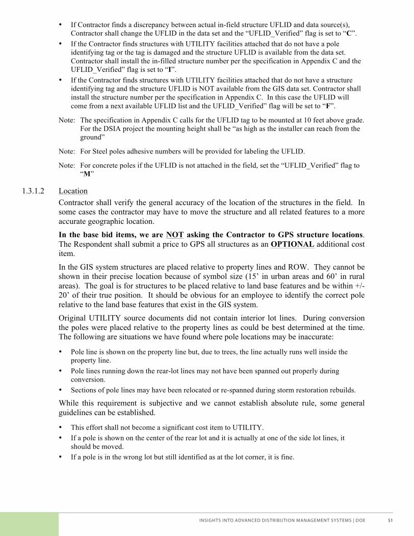
INSIGHTS INTO ADVANCED DISTRIBUTION MANAGEMENT SYSTEMS | DOE 51
UTILITY DSIA RFP 10 11/02/2006
• If Contractor finds a discrepancy between actual in-field structure UFLID and data source(s), Contractor shall change the UFLID in the data set and the “UFLID_Verified” flag is set to “C”.
• If the Contractor finds structures with UTILITY facilities attached that do not have a pole identifying tag or the tag is damaged and the structure UFLID is available from the data set. Contractor shall install the in-filled structure number per the specification in Appendix C and the UFLID_Verified” flag is set to “I”.
• If the Contractor finds structures with UTILITY facilities attached that do not have a structure identifying tag and the structure UFLID is NOT available from the GIS data set. Contractor shall install the structure number per the specification in Appendix C. In this case the UFLID will come from a next available UFLID list and the UFLID_Verified” flag will be set to “F”.
Note: The specification in Appendix C calls for the UFLID tag to be mounted at 10 feet above grade. For the DSIA project the mounting height shall be “as high as the installer can reach from the ground”
Note: For Steel poles adhesive numbers will be provided for labeling the UFLID.
Note: For concrete poles if the UFLID is not attached in the field, set the “UFLID_Verified” flag to “M”
1.3.1.2 Location Contractor shall verify the general accuracy of the location of the structures in the field. In some cases the contractor may have to move the structure and all related features to a more accurate geographic location. In the base bid items, we are NOT asking the Contractor to GPS structure locations. The Respondent shall submit a price to GPS all structures as an OPTIONAL additional cost item.
In the GIS system structures are placed relative to property lines and ROW. They cannot be shown in their precise location because of symbol size (15’ in urban areas and 60’ in rural areas). The goal is for structures to be placed relative to land base features and be within +/-20’ of their true position. It should be obvious for an employee to identify the correct pole relative to the land base features that exist in the GIS system. Original UTILITY source documents did not contain interior lot lines. During conversion the poles were placed relative to the property lines as could be best determined at the time. The following are situations we have found where pole locations may be inaccurate:
• Pole line is shown on the property line but, due to trees, the line actually runs well inside the property line.
• Pole lines running down the rear-lot lines may not have been spanned out properly during conversion.
• Sections of pole lines may have been relocated or re-spanned during storm restoration rebuilds.
While this requirement is subjective and we cannot establish absolute rule, some general guidelines can be established.
• This effort shall not become a significant cost item to UTILITY. • If a pole is shown on the center of the rear lot and it is actually at one of the side lot lines, it
should be moved. • If a pole is in the wrong lot but still identified as at the lot corner, it is fine.
Voices of Experience | Advanced Distribution Management Systems_brochure.indd 51 2/11/15 12:52 PM

INSIGHTS INTO ADVANCED DISTRIBUTION MANAGEMENT SYSTEMS | DOE52
UTILITY DSIA RFP 11 11/02/2006
• Where there are no visually identifiable land base features controlling the placement of individual poles, their location is less important. These pole locations will be judged relative to poles that are controlled by land base features.
1.3.1.3 Pole Top Configuration Contractor shall identify and record the pole top configuration style as identified in Appendix D of this RFP. Please note that while there are many construction variations (tangent, angle, corner, double dead end, etc.) possible within a given configuration style, we are only looking for the pole top configuration style which will generally remain consistent for a section of line.
If an actual pole top configuration style is not available from the selections in Table D-1, Contractor shall select “other” and take a digital photograph of the pole top showing the phase and neutral conductor spatial relationships.
1.3.1.4 Wood Pole Age and Other Attributes The age of our structures has been identified as one of the key data item for most asset reliability and aging studies. During any previous inspections (pole treatment, joint use, etc.) contractors have been instructed to only capture pole attribute (Ownership, Year of Mfgr, Height, and Class) data if it was legible from the pole brand. As a result UTILITY only has the Age on 18% of our single pole structures.
The contractor will validate/capture the Year of Mfgr. and other pole attributes for all steel and concrete poles based on the manufacture markings. This will require the contractor to closely inspect approximately 2,000 of these type poles. For wood pole structures the Contractor will not be expected to inspect each pole but rather will be allowed to use ‘engineering judgment’ to validate/capture the Year of Mfgr. and other pole attributes.
• For line sections that were constructed at the same time (apparent from dead ends, etc.) and all (or the majority of) poles are of the same vintage, the Contractor can use existing GIS or field data of one pole to populate the pole information on all similar poles. (An educated determination is better than no information).
• For poles that visibly conflict with the GIS information provided, the Contractor will capture new information by inspecting the pole brand or where multiple poles are involved the previous method can be used.
• For poles in a pole line that are visibly newer than the rest of the line, and the information provided by GIS appear to be incorrect, the Contractor will capture new information by inspecting the pole brand.
It is expected that with these methods of determining pole age and attribution, the data capture costs for these attributes will be minimal as it minimizes the number of pole brands the Contractor will need to visually inspect. Where these ‘engineering judgment’ methods are used we expect that pole height will be determined within +/-5 feet; pole class will be determined within +/- one UTILITY standard class; age will be determined +/- 5 years of actual age; and material grade (cedar, pine, etc.) will be determined with the standard data accuracy requirement. In the base bid items, the Contractor will assume the above process. The Respondent shall submit a price to visually inspect the pole brand of all poles to determine age and other attributes as an OPTIONAL additional cost item. For poles where the pole brand is not legible, the above process shall then be used.
Voices of Experience | Advanced Distribution Management Systems_brochure.indd 52 2/11/15 12:52 PM
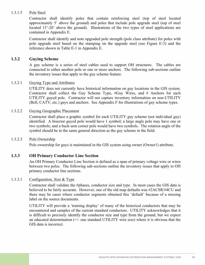
INSIGHTS INTO ADVANCED DISTRIBUTION MANAGEMENT SYSTEMS | DOE 53
UTILITY DSIA RFP 12 11/02/2006
1.3.1.5 Pole Steel Contractor shall identify poles that contain reinforcing steel (top of steel located approximately 5’ above the ground) and poles that include pole upgrade steel (top of steel located 15’-20’ above the ground). Illustrations of the two types of steel applications are contained in Appendix E.
Contractor shall identify and note upgraded pole strength (pole class attribute) for poles with pole upgrade steel based on the stamping on the upgrade steel (see Figure E-3) and the reference shown in Table E-1 in Appendix E.
1.3.2 Guying Scheme A guy scheme is a series of steel cables used to support OH structures. The cables are connected to either another pole or one or more anchors. The following sub-sections outline the inventory issues that apply to the guy scheme feature.
1.3.2.1 Guying Type and Attributes UTILITY does not currently have historical information on guy locations in the GIS system. Contractor shall collect the Guy Scheme Type, #Guy Wires, and # Anchors for each UTILITY guyed pole. Contractor will not capture inventory information on non-UTILITY (Bell, CATV, etc.) guys and anchors. See Appendix F for illustrations of guy scheme types.
1.3.2.2 Guying Geographic Placement Contractor shall place a graphic symbol for each UTILITY guy scheme (not individual guy) identified. A bisector guyed pole would have 1 symbol; a large angle pole may have one or two symbols; and a buck-arm corner pole would have two symbols. The rotation angle of the symbol should be in the same general direction as the guy scheme in the field.
1.3.2.3 Pole Ownership Pole ownership for guys is maintained in the GIS system using owner (Owner1) attribute.
1.3.3 OH Primary Conductor Line Section An OH Primary Conductor Line Section is defined as a span of primary voltage wire or wires between two poles. The following sub-sections outline the inventory issues that apply to OH primary conductor line sections.
1.3.3.1 Configuration, Size & Type Contractor shall validate the #phases, conductor size and type. In most cases the GIS data is believed to be fairly accurate. However, one of the old map defaults was #2ACSR/#4CU and there may be cases where conductor segments obtained this ‘default’ because of a missing label on the source documents. UTILITY will provide a ‘training display’ of many of the historical conductors that may be encountered and samples of the current standard conductors. UTILITY acknowledges that it is difficult to precisely identify the conductor size and type from the ground, but we expect an educated determination (+/- one standard UTILITY wire size) where it is obvious that the GIS data is incorrect.
Voices of Experience | Advanced Distribution Management Systems_brochure.indd 53 2/11/15 12:52 PM
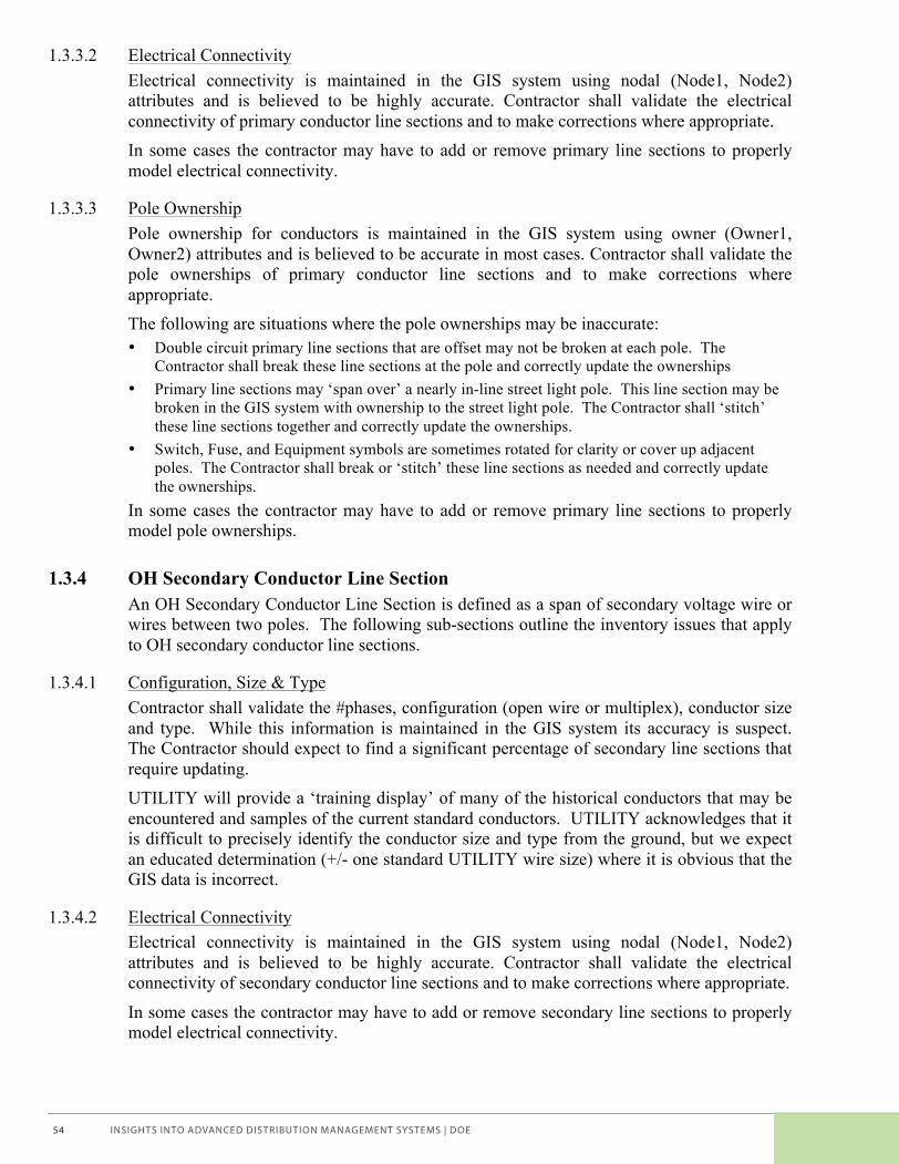
INSIGHTS INTO ADVANCED DISTRIBUTION MANAGEMENT SYSTEMS | DOE54
UTILITY DSIA RFP 13 11/02/2006
1.3.3.2 Electrical Connectivity Electrical connectivity is maintained in the GIS system using nodal (Node1, Node2) attributes and is believed to be highly accurate. Contractor shall validate the electrical connectivity of primary conductor line sections and to make corrections where appropriate. In some cases the contractor may have to add or remove primary line sections to properly model electrical connectivity.
1.3.3.3 Pole Ownership Pole ownership for conductors is maintained in the GIS system using owner (Owner1, Owner2) attributes and is believed to be accurate in most cases. Contractor shall validate the pole ownerships of primary conductor line sections and to make corrections where appropriate. The following are situations where the pole ownerships may be inaccurate: • Double circuit primary line sections that are offset may not be broken at each pole. The
Contractor shall break these line sections at the pole and correctly update the ownerships • Primary line sections may ‘span over’ a nearly in-line street light pole. This line section may be
broken in the GIS system with ownership to the street light pole. The Contractor shall ‘stitch’ these line sections together and correctly update the ownerships.
• Switch, Fuse, and Equipment symbols are sometimes rotated for clarity or cover up adjacent poles. The Contractor shall break or ‘stitch’ these line sections as needed and correctly update the ownerships.
In some cases the contractor may have to add or remove primary line sections to properly model pole ownerships.
1.3.4 OH Secondary Conductor Line Section An OH Secondary Conductor Line Section is defined as a span of secondary voltage wire or wires between two poles. The following sub-sections outline the inventory issues that apply to OH secondary conductor line sections.
1.3.4.1 Configuration, Size & Type Contractor shall validate the #phases, configuration (open wire or multiplex), conductor size and type. While this information is maintained in the GIS system its accuracy is suspect. The Contractor should expect to find a significant percentage of secondary line sections that require updating. UTILITY will provide a ‘training display’ of many of the historical conductors that may be encountered and samples of the current standard conductors. UTILITY acknowledges that it is difficult to precisely identify the conductor size and type from the ground, but we expect an educated determination (+/- one standard UTILITY wire size) where it is obvious that the GIS data is incorrect.
1.3.4.2 Electrical Connectivity Electrical connectivity is maintained in the GIS system using nodal (Node1, Node2) attributes and is believed to be highly accurate. Contractor shall validate the electrical connectivity of secondary conductor line sections and to make corrections where appropriate.
In some cases the contractor may have to add or remove secondary line sections to properly model electrical connectivity.
Voices of Experience | Advanced Distribution Management Systems_brochure.indd 54 2/11/15 12:52 PM
INSIGHTS INTO ADVANCED DISTRIBUTION MANAGEMENT SYSTEMS | DOE 55
UTILITY DSIA RFP 14 11/02/2006
1.3.4.3 Pole Ownership Pole ownership for conductors is maintained in the GIS system using owner (Owner1, Owner2) attributes and is believed to be accurate in most cases. Contractor shall validate the pole ownerships of secondary conductor line sections and to make corrections where appropriate.
The following are situations where the pole ownerships may be inaccurate: • Multi-circuit secondary line sections that are offset may not have proper ownerships set. The
Contractor shall correctly update the ownerships. • Secondary line sections may not be shown attached to the correct pole. Contractor shall correct
the secondary attachment location graphically and correctly update the ownerships. In some cases the contractor may have to add or remove secondary line sections to properly model pole ownerships.
1.3.4.4 Utility Use Contractor is required to validate the ‘Utility Use’ attribute on secondary line sections. Most secondary line sections will have the utility use set to ‘Secondary’. When the secondary line section serves only street lights (no services, meters, or un-metered loads) the utility use will be set to ‘STLT’. If the secondary line section serves only Area Lights (typically on private property) the utility use will be set to ‘AREA LIGHT.
1.3.5 OH Service Lines OH Service Lines are defined as a span of service level voltage wire or wires between a pole and the customer’s point-of-service (POS), typically a service mast. The following sub-sections outline the inventory issues that apply to OH service lines.
1.3.5.1 GIS Service and POS Background Historically, services were never mapped at UTILITY and a customer-to-transformer relationship had never been established. As we constructed the GIS system we programmatically placed POS features at addresses and in the center of property parcels. Services were then constructed between the POS and the nearest pole with secondary conductor. This process had an immediate benefit in that it established a customer-to-transformer relationship with each customer (address). However, because of multi-address buildings, it created more POS and services than actually exist, i.e. ‘fans’ and sometimes incorrectly connected customers to the wrong transformer.
1.3.5.2 Configuration, Size & Type Contractor shall collect/validate the OH/UG flag, #phases, configuration (open wire or multiplex), conductor size and type. While services are modeled in the GIS this information is currently not maintained. UTILITY will provide a ‘training display’ of many of the historical conductors that may be encountered and samples of the current standard conductors. UTILITY acknowledges that it is difficult to precisely identify the conductor size and type from the ground, but we expect an educated determination (+/- one standard UTILITY wire size) where it is obvious that the GIS data is incorrect.
Voices of Experience | Advanced Distribution Management Systems_brochure.indd 55 2/11/15 12:52 PM
INSIGHTS INTO ADVANCED DISTRIBUTION MANAGEMENT SYSTEMS | DOE56
UTILITY DSIA RFP 15 11/02/2006
1.3.5.3 Electrical Connectivity Electrical connectivity is maintained in the GIS system using nodal (Node1 connects to the service, Node2 connects to the POS) attributes and is believed to be highly accurate. Contractor shall validate the electrical connectivity of service conductors and to make corrections where appropriate. Where the secondary conductors are open at a pole (modeled with a secondary “open” node), the service must be connected to the correct node of the secondary node.
In some cases the contractor may have to add or remove services and POS features to properly model electrical connectivity.
1.3.5.4 Pole Ownership Pole ownership for services is maintained in the GIS system using owner (Owner1 to POS, Owner2 to pole attributes and is believed to be accurate in most cases. Contractor shall validate the pole ownerships of services and to make corrections where appropriate. The Contractor may have to graphically move a service from one pole to an adjacent pole and correct the owner attribute. In some cases the Contractor may have to add or remove services to properly model electrical connectivity.
1.3.6 POS to Customer Connection The POS to Customer relationship is stored in UTILITY’s Customer Information System (CIS) system and is updated daily by automated GIS processes. As outlined in Section 1.3.5.1, this relationship was established programmatically and is fairly accurate in single-family neighborhoods. The POS-to-customer relationship becomes less reliable in commercial and congested areas. Typical situations where customers are not connected to the correct POS include:
• Strip malls with multiple addresses with one service/POS. Many of these were programmatically created with multiple POS and service drops.
• Apartment and condominium buildings with multiple service/POS locations may be missing service/POS locations and/or have customers connected to the wrong POS.
The contractor will record the meter numbers for each POS/service line having more than one meter. UTILITY meters also have the meter number bar-coded on the face of the meter. If the contractor uses a bar-code scanner to collect this information, their application must ensure that they capture a properly formatted meter number. Contractor shall field verify any meter number discrepancies at Contractor’s expense. Note: In the pilot we did not have the field validation of the meter number format that was scanned. During the post processing we found a small percentage of meter numbers that were too short or had alpha characters imbedded. We believe this was due to scanning the bar code through the plastic lens.
1.3.7 Equipment Features The following sub-sections outline the inventory issues that apply to all electrical equipment features. Subsequent sections will outline specific issues for several features.
1.3.7.1 Feature Existence Validation Electrical equipment features are maintained in the GIS system and are believed to be highly accurate. However, in some cases the equipment may not be located on the correct pole.
Voices of Experience | Advanced Distribution Management Systems_brochure.indd 56 2/11/15 12:52 PM
INSIGHTS INTO ADVANCED DISTRIBUTION MANAGEMENT SYSTEMS | DOE 57
UTILITY DSIA RFP 16 11/02/2006
The Contractor may have to graphically move an equipment feature from one pole to an adjacent pole and correct the electrical connectivity and ownership. In some cases the Contractor may have to add or remove equipment features to properly model current field situations.
1.3.7.2 Attribute Validation Most attribute information for electrical features is maintained in the GIS system. Contractor shall validate (and in some cases collect) the attribute information as identified in Table 1. In most cases the GIS data is believed to be fairly accurate.
1.3.7.3 Lightning Protection Location Several electrical devices are protected by lightning arresters. Contractor shall capture the ‘Protection Location’ for specific equipment features as outlined in Table 1. Illustration of the various lightning arrester protection location types is contained in Appendix F.
1.3.7.4 Electrical Connectivity Electrical connectivity is maintained in the GIS system using nodal (Node1, Node2) attributes and is believed to be highly accurate. Most features are two node devices (Node1<>Node2), but some are single node devices (Node1=Node2). Contractor shall validate the electrical connectivity of electrical equipment and to make corrections where appropriate.
1.3.7.5 Pole Ownership Pole ownership for electrical equipment is maintained in the GIS system using owner (Owner1 to pole) attributes and is believed to be accurate in most cases. Contractor shall validate the pole ownerships of electrical equipment and to make corrections where appropriate.
1.3.7.6 Graphic Symbol Placement & Rotation Most equipment features are represented as symbols with an insertion point at one edge (source, usually Node1) the symbols are typically placed with this insertion point common to the center of the structure feature to which it is mounted. The symbol is rotated so that the opposite side of the symbol (load, usually Node2) is in line with the conductor to which it is connected. Other conventions apply for special circumstances (double circuits, etc.) and will be discussed during the project start-up phase.
1.3.8 OH Transformer Features The following sub-sections outline the additional inventory issues that apply to overhead transformer features.
1.3.8.1 Transformer Type Contractor shall collect/validate the Transformer Type in addition to other general attribute information. The majority of UTILITY’s overhead transformers are ‘Conventional’, but for a period of years we purchased CSP (completely self protected) transformers. Appendix F contains illustrations that show the different characteristics of the two types.
Voices of Experience | Advanced Distribution Management Systems_brochure.indd 57 2/11/15 12:52 PM

INSIGHTS INTO ADVANCED DISTRIBUTION MANAGEMENT SYSTEMS | DOE58
UTILITY DSIA RFP 17 11/02/2006
1.3.8.2 Electrical Connectivity Electrical connectivity for transformers is maintained in the GIS system using nodal (Node1 connects to Primary Conductor, Node2 connects to Secondary) attributes and is believed to be highly accurate. Contractor shall validate the electrical connectivity of transformers and to make corrections where appropriate.
1.3.9 Switch Features The following sub-sections outline the additional inventory issues that apply to switch features.
1.3.9.1 Switch Type Contractor shall collect/validate the Switch Type in addition to other general attribute information. The majority of UTILITY’s overhead switches are 600 amp ‘Underslung’ or 300 amp ‘Cutout’. ‘Cutout’ switches are similar to Fuse ‘Cutouts’ but, they have a solid blade instead of the fuse tube. Appendix F contains illustrations that show the different characteristics of the various types of overhead switches.
1.3.10 Area Light Features The following sub-sections outline the additional inventory issues that apply to area (dusk-to-dawn) features.
1.3.10.1 Area Light Type UTILITY does not currently have historical information on Area Lights features in the GIS system. Contractor shall collect the “Light Type” classification for each light found. Appendix F contains illustrations that show the characteristics of the various types of Area Lights.
1.3.10.2 Geographic Placement Contractor shall place a graphic symbol for each UTILITY Area Light identified. The rotation angle of the symbol should be in the same general direction as the light in the field.
1.3.11 AMR Features The following sub-sections outline the additional inventory issues that apply to AMR communication features.
1.3.11.1 Geographic Placement AMR features were placed in the GIS system based on an geographic coordinates (XY) provided by the AMR installation vendor. Contractor shall move the GIS graphic symbol for each AMR feature to the pole to which it is attached.
1.3.12 Primary Conductor Phase Determination The UTILITY GIS data maintains the system phasing information. For all laterals and equipment the Contractor shall verify the phasing information. UTILITY has rigorously followed a phasing convention based on structure position outlined below. Where phasing differs from this convention it is marked in the field and circuit maps.
Voices of Experience | Advanced Distribution Management Systems_brochure.indd 58 2/11/15 12:52 PM

INSIGHTS INTO ADVANCED DISTRIBUTION MANAGEMENT SYSTEMS | DOE 59
UTILITY DSIA RFP 18 11/02/2006
1.3.12.1 Standard System Phasing Layout Typical system phasing is A-B-C West to East and North to South for crossarm or bracket construction. For vertical and armless construction the configuration is A-B-C from top to bottom.
1.3.12.2 Neutral Conductor Layout For unshielded construction the neutral (if present) is located below the primary conductors and above the secondary and/or communication conductors. The neutral conductor is usually attached on the street side of the pole on unshielded configurations.
On shielded construction the neutral conductor is located at the top of the pole as a “shield” wire.
UTILITY commonly builds common neutral construction where there is no primary neutral wire and the primary relies on the secondary system neutral.
1.3.13 Pictures Contractor will obtain a digital photograph of a situation when specified in other sections/subsections of this RFP.
In the base bid items, we are NOT asking the Contractor to photograph each pole.
1.3.13.1 Camera Specifications During the DSIA pilot the contractor used a 3-mega pixel digital camera with a 6X optical zoom. A camera with these (or greater) specifications will provide the quality photographs desired.
1.3.13.2 Inventory Photos As specified in Section 1.3.1.3, Contractor shall document any non-standard pole top configurations. The Contractor shall obtain a photograph that clearly shows the pole top configuration being highlighted. The Contractor will also link this photograph with the location (UFLID).
1.3.13.3 Assessment Condition Photos Contractor shall document asset assessment conditions by taking a photograph of the condition when specified in Table 2. The Contractor shall obtain a photograph that clearly shows the condition being highlighted. The Contractor will also link this photograph with the location (UFLID) and the assessment condition issue being recorded.
1.3.13.4 Option – Pricing to Photograph All Poles In the Pricing spreadsheet the Respondent shall provide an optional price quote to obtain a photograph of all structures. UTILITY would expect that these photographs would be framed to 1) maximize the structure in frame, 2) show the entire structure, ground to pole-top, but 3) include any relevant environmental items of interest.
Voices of Experience | Advanced Distribution Management Systems_brochure.indd 59 2/11/15 12:52 PM
INSIGHTS INTO ADVANCED DISTRIBUTION MANAGEMENT SYSTEMS | DOE60
UTILITY DSIA RFP 19 11/02/2006
1.4 Typical Field Inventory Update Transactions 1.4.1.1 Map Corrections, Pole locations not correct on maps
Contractor may encounter situations where UTILITY poles are represented on the maps in a significantly incorrect location. The Contractor will correct the pole locations using their field data collection tool and provide an appropriate GIS feature update transactions for all effected facilities. The specific process will be established by mutual agreement of UTILITY and the Contractor.
1.4.1.2 Map Corrections, Poles Not Found on Map Contractor may encounter situations where UTILITY facilities are attached to poles that do not appear on maps. The Contractor will report the found pole using their field data collection tool, create a uniquely identifiable UFLID (using the UFLID physically on the pole or from a list of unused UFLIDs provided by UTILITY when the pole in the field is not marked) for the pole and collect all required attributes. The Contractor will provide an appropriate GIS job insert transaction for the new pole and appropriate feature update transactions for all effected facilities. The specific process will be established by mutual agreement of UTILITY and the Contractor.
1.4.1.3 Map Corrections, Facilities Not Found on Map Contractor may encounter situations where UTILITY facilities are found that do not appear on maps. The Contractor will report the found facilities using their field data collection tool and collect the required information in the same manner as for known facilities. The Contractor will provide an appropriate GIS job insert transaction for the new facility and appropriate feature update transactions for all effected facilities. The specific process will be established by mutual agreement of UTILITY and the Contractor.
1.4.1.4 Map Corrections, Conductors Not Found on Map Contractor may encounter situations where UTILITY conductors installed in the field do not appear on maps. The Contractor will report the found conductor using their field data collection tool, assign a uniquely identifiable UCSID (from a list of unused UCSIDs provided by UTILITY) for the conductor segment and collect the required information in the same manner as for known conductors. The Contractor will provide an appropriate GIS job insert transaction for the new conductor and appropriate feature update transactions for all effected facilities. The specific process will be established by mutual agreement of UTILITY and the Contractor.
1.4.1.5 Map Corrections, Facilities Found on Different Pole Contractor may encounter situations where UTILITY facilities are found on different poles than as they appear on maps. The Contractor will identify the correct structure for the facility and report the correct location and other DSIA information using their field data collection tool. The Contractor will provide an appropriate GIS job update transaction for the new facility location and appropriate feature update transactions for all effected facilities. The specific process will be established by mutual agreement of UTILITY and the Contractor.
1.4.1.6 Map Corrections, Facilities Not Found in the Field Contractor may encounter situations where UTILITY facilities are shown on the maps that no longer exist in the field. The Contractor will report the missing facility using their field
Voices of Experience | Advanced Distribution Management Systems_brochure.indd 60 2/11/15 12:52 PM
INSIGHTS INTO ADVANCED DISTRIBUTION MANAGEMENT SYSTEMS | DOE 61
UTILITY DSIA RFP 20 11/02/2006
data collection tool and provide an appropriate GIS job delete feature transaction for the new pole and appropriate feature update transactions for all effected facilities. The specific process will be established by mutual agreement of UTILITY and the Contractor.
1.4.1.7 Customer-to-POS Association Contractor has been required to capture meter numbers for POS that have multiple meters. The Contractor will report this using their field data collection tool with a bar-code scanner. This information is not maintained in the GIS system, therefore this information will not flow through the GIS job environment. The Contractor will provide this data in a simple three-column table by delivery unit (Delivery_Unit, POS, MeterNum) The specific process will be established by mutual agreement of UTILITY and the Contractor.
1.5 Condition Assessment Requirements The following points outline additional condition assessment considerations and requirements that could not be adequately described in Table 2. • Asset assessment conditions will be collected at the structure features and for each linear feature. • For each asset assessment condition reported the following attributes must be collected.
(Associated feature ID; assessment item from Table 2; quantity; priority code) • Multiple asset assessment conditions can be noted for each structure or linear feature. • Unless noted in Table 2 pictures will NOT be taken for Non-Standard conditions • Unless noted in Table 2 pictures will be taken for Maintenance conditions
Many of the asset assessment conditions listed in Table 2 are illustrated in Appendix G. UTILITY will work with the Contractor to establish additional asset assessment condition reporting guidelines during the development of the project Procedures Manual.
Voices of Experience | Advanced Distribution Management Systems_brochure.indd 61 2/11/15 12:52 PM

INSIGHTS INTO ADVANCED DISTRIBUTION MANAGEMENT SYSTEMS | DOE62
Leadership Team
Tom BialekSan Diego Gas & Electric
Jared GreenElectric Power Research Institute
Becky HarrisonGridWise Alliance
Gregg KnightCenterPoint Energy
Puesh KumarAmerican Public Power Association
Tony ThomasNational Rural Electric Cooperative Association
Joseph WaligorskiFirstEnergy
U.S. Department of Energy Team
Eric LightnerU.S. Department of Energy
Tanya BurnsEnergetics Incorporated
Sonja BerdahlNational Renewable Energy Laboratory
Participants
Nicholas Abi-SamraCenterPoint Energy
Hong AblackCenterPoint Energy
Michael AdamsLebanon Utilities
Walter BartelCenterPoint Energy
Stephen CallahanIBM
Brian ConroyIberdrola USA
Daniel BowdenDTE Energy Electric
Normand BrienNew Hampshire Electric Cooperative, Inc.
Kari GlassPacifi c Gas & Electric Company
Gary CassilagioPacifi c Gas & Electric Company
Jeff ColemanBerkeley Electric Cooperative
William ErnzenAccenture
Andrea DennisOklahoma Gas & Electric
Brian DickieNortheast Utilities
Robert JaguschMinnesota Municipal Utilities Association
John GagnonAccenture
Arthur GonzalezAustin Energy
Robby HamlinCoServ Electric
Edward HedgesKansas City Power & Light Co.
Tuba KhawajaCenterPoint Energy
Chris HeimgartnerSnohomish County Public Utility District
Milton HollowayCenter for the Commercialization of Electric Technologies
Michael JohnsonDuke Energy
Aseem KapurCon Edison
Damon LoboiPublic Service Enterprise Group Incorporated
Allan LongMemphis Light, Gas and Water Division
Adam MathenyFirstEnergy
Diane MarshDuke Energy
Kenneth MercadoCenterPoint Energy
Katarina MiletijevSacramento Municipal Utility District
Jeff MitlerPepco Holdings, Inc.
Philip MorneaultIberdrola USA
Richard MurphyCenter for the Commercialization of Electric Technologies
Jeff MyersonCenterPoint Energy
Ricky OrumCenterPoint Energy
Pradeep PatraFlorida Power & Light
Chip PinionMiddle Tennessee Electric Membership Corporation
Appendix C: DOE ADMS Working Group Members
Voices of Experience | Advanced Distribution Management Systems_brochure.indd 62 2/11/15 12:52 PM

INSIGHTS INTO ADVANCED DISTRIBUTION MANAGEMENT SYSTEMS | DOE 63
Dan RimelspachFirst Energy Corporation
Quentin RogersPowder River Energy Corp.
Lisa RouseFirstEnergy
Camilo SernaNortheast Utilities
Bruce StephensGunnison County Electric Association
Heather StoryDTE Energy Electric
Dave TomczyszynAustin Energy
Steven ZinserPublic Service Enterprise Group Incorporated
Pat WilliamsEast Mississippi Electric Power Association
Kyle WoodFirstEnergy
Voices of Experience | Advanced Distribution Management Systems_brochure.indd 63 2/11/15 12:52 PM

INSIGHTS INTO ADVANCED DISTRIBUTION MANAGEMENT SYSTEMS | DOE64
DOE/GO-OT-6A42-63689 • February 2015
Voices of Experience | Advanced Distribution Management Systems_brochure.indd 64 2/11/15 12:52 PM