visual weld acceptance criteriadeveloping weld acceptance criteria and inspection guidance for...
TRANSCRIPT
~ectric Power.search Institute
Topics:WeldingNuclear power plantsConstructionInspection
Enclosure 2
EPRI NP-5380Volume 2Project 0101Final ReportSeptember 1987
Visual Weld Acceptance CriteriaVolume 2: Sampling Phn for VisualReinspection of Welds (NCIG-02, Revision 2)
Prepared byNuclear Construction Issues Group
- 8803220y7gPDR pO 8803gg.
0500027~DCD™
0
Jl
0
ABSTRACT
The Kuclear Construction Issues Group (NCIG) was formed to resolve co+non problems
being experienced at nuclear power plants in the assurance of hardware quality forwhich common solutions likely existed. The initial activity undertaken by thisgroup was development of visual weld acceptance criteria and inspection guidance
for structural welds. This report documents the results of this NCIG activity and
is composed of:
Volume 1 Visual Keld Acceptance Criteria for Structural Kelding at NuclearPower Plants (NCIG-01, Revision 2)
Volume 2 Sampling Plan for Visual Reinspection of Kelds (NCIG-02, Revision 2)
Volume 3 Training Manual for Inspectors of Structural fields at Kuclear PowerPlants using the Acceptance Criteria of NCIG-01 (NCIG-03,Revision 1)
Volumes 1, 2, and 3 are published in entirety as prepared by KCIG and formerlyreferenced as KCIG-01, NCIG-02, and NCIG-03, respectively. Volume 3 includes
errata previously approved by NCIG but not incorporated into a revision of the
original NCIG-03 document. Thus, Volume 3 is identified as NCIG-03, Revision l.Errata incorporated in Volume 3 are identified by vertical bars in the rightmargin.
0
k
IK
E
I
PREFACE
In early 1984, representat1ves of the nuclear industry met for a nuclearconstruct1on issues forum sponsored by the Amer1can Society of Hechnical Engineers
(ASIDE). The consensus of the forum was that utilities currently constructingnuclear generat1ng stations were experiencing co+non problems in the assurance ofhard~are quality for which coneon solutions likely existed and which should be
pursued in some manner.
At subsequent meetings of utility representatives, it was agreed that althoughthere are a number of construction issues which could be addressed, the task ofdeveloping weld acceptance criteria and inspection guidance for structural weldsshould be the first task undertaken by a utility group. The Nuclear ConstructionIssues Group (NCIG) was formed and undertook the development of visual weld
acceptance criteria. This Visual Meld Acceptance Criter1a (VWAC) task subsequentlyresulted in a VWAC manual, Sampling Plan, Training Hanual and an ASME Code Case
for s1milar type welds. The Nuclear Regulatory Commission (NRC) issued a
favorable review letter for VWAC on June 26, 1985 (Appendix A of Volume I) and forthe Sampling Plan on April 9, 1987 (Appendix 8 of Volume 2). Since initial NRC
acceptance, VWAC has been implemented at a number of nuclear plants. In addition,ASME Code Case N-430 allowing the use of VWAC for code supports has been approvedand published by ASHE (Appendix B of Volume I). This document is the first NCIG
product published as an EPRI report and is a compilation of the VMAC manual
(Volume I), the Sampling Plan (Volume 2), and the Training Manual (Volume 3).
Contributing to the timely development and success of VWAC was the voluntaryparticipation by a number of technical representatives from architect/engineer(A/E) organizations and a direct, positive 1nteraction with NRC regulatory staffthroughout the duration of the task.
With the completion of VWAC, the HCIG members decided to pursue a number ofadditional tasks designed to provide effective industry resolution of issuesassociated w1th engineering, construction, mod1fication, and repair of nuclearpower plants. In December 1985, NCIG members requested EPRI to serve as Program
0
I *
Manager for HCIG and EPRI accepted this responsib111ty. HCIG has now been
established as a separately funded EPRI Owners'roup Program.
The goals and obfectives of the Nuclear Construction Issues Group are to:
Develop a comnon approach to the resolut1on of issues regardingnew construction, modification and repair of operat1ng nuclearpower plants that are acceptable to the nuclear industry andthe NRC, as appropriate.
Provide a means of sharing information and concerns withprofess1onal organizations and societies for obta1ning theirinvolvement and support in the resolution of NCIG issues.
Provide continuing support to the documents developed by HCIGto mainta1n consistency w1th 1ndustry changes until such timeas these documents are incorporated, as appropriate, intoestablished consensus standards.
Support the needs of the NCIG Members and pursue thosetechnical Tasks wh1ch have a general applicat1on to the1ndustry.
Provide a Forum for sharing information on nuclear issues forthe concerned organizations, i.e., utilities, A/E's,constructors, proFessional organizations and societies,industry, and the HRC.
Twenty-two (22) domestic utilites and eight (8) A/E organizations support NCIG
activities. Utilities who accept and fund one or more NCIG tasks are designatedas HCIG Members. Other utilit1es, wh1le not funding HCIG tasks, provide activetechnical support and participation 1n HCIG activities.
Utilities supporting NCIG are:
Arkansas Power & LightArizona Public Service CompanyCarolina Power & LightCommonwealth EdisonOuke Power CompanyGeorgia Power CompanyGPU HuclearGulf States UtilitiesHouston Lighting & PowerIllinois Power CompanyIowa Electric Light & Power
Kansas Gas & ElectricNew Hampshire YankeeHiagara MohawkPacific Gas & ElectricPhiladelph1a ElectricSouthern Cal1fornia EdisonTennessee Valley AuthorityTU ElectricUnion ElectricV1rginia Power CompanyWashington Public Power Supply System
The A/E organizations currently support1ng NCIG on a regular, voluntary basis are:
Bechtel Power CorporationBlack 8 VeatchEbasco Services, Inc.Gibbs C Hill, Inc.
Gilbert/Ceanonwealth, Inc.Sargent 4 Lundy EngineersSouthern Company ServicesStone 4 Webster Engineering
HCIG operates as a separately funded EPRI Owners'roup Program. The HCIG
organization 1s structured to rap1dly develop effective engineering solutions toplant modifications and construction problems affecting a number of ut111ties.HCIG meets every 2-3 months and is chaired by a selected utility representative.Candidate HCIG tasks are proposed by 1nterested ut1lities. Once approved by HCIG,
the tasks are led by a ut1lity task chairman. In general, a contractor under
contract to EPRI is responsible for completion of all or part of an HCIG task.Ass1stance in completing a task 1s provided by staff from NCIG utilities,
'nterestedA/E organizations on a volunteer basis, and EPRI staff. Meetings are
held on indiv1dual task subjects as necessary. Task status 1s reported to HCIG by
the task chairman at the NCIG meetings. Completion of a task will usually involvereview and acceptance of a task product by the HRC and/or adoption by the
appropriate codes and standards group. This broad participation helps ensure theusefulness and quality of the HCIG task products and strengthens KCIG recognitionas representative of the nuclear ut1lity industry.
EPRI, serving as the NCIG Program Hanager, provides technical, administrative and
contractual management. EPRI )ointly funds HCIG activities.
NCIG 1s sponsoring several tasks which are currently being performed forcompletion in 1987. The products of these tasks may also be published as EPRI
reports.
The results of the various NCIG efforts have established the effectiveness oF theHCIG organization and approach. Utility leadership and A/E participation helpsensure the usefulness and quality of the HCIG task products and strengthens HCIG
recognition as representative of the nuclear ut1lity industry.
The HCIG approach of generic resolut1on of high priority plant engineering and
construction issues based on accumulated industry experience and sound eng1neeringprinciples represents a prudent ut111zation of 1ndustry resources.
vii
ACKHOWLEDGMEHT
The following personnel participated in the development of this document:
John Adkins
Nohianad Amin
Douglas Dutton
Bob Jessee
Tony Mark
Roger Reedy
Amad Shaabar
Bob Small
Ruble Thomas
Walter Weber
John White
Paul Wilson
Southern Company ServicesSargent and Lundy
Southern Company ServicesTennessee Valley AuthorityBechtel Power CorporationReedy AssociatesEbasco Services, Inc.Sargent and Lundy
Southern Company ServicesUnion ElectricTennessee Valley AuthorityStone & Webster
CONTEHTS
Section
1 IHTRODUCTION
1.1 Background
1.2 Purpose and Scope
1.3 Implementation
1.4 Plan Su+nary
1.5 Contents
2 DEFINITIONS
2. 1 Inspection Item
2.2 Discrepant Weld, Discrepant Item
2.3 Population2.4 Cumulative Sample Size, n
2.5 Cumulative Humber of Discrepant Items, dn
2.6 Percent Discrepant, p
2.7 Acceptance Humber, an
2.8 Rejection Humber, rn2.9 Engineering Evaluation2.10 Inaccessible Item
2. 11 Symbol s
3 SAMPLING PROCEDURE
3. 1 Population and Reinspection Attributes3.2 Sampling Plan Type
3.3 Procedure for Single Sampling Plan
3.4 Procedure for Multiple Sampling Plan
APPEHDIX A COMMENTARY
APPENDIX B HRC Letter Accepting Sampling Plan for VisualReinspection of Welds (HCIG-02, Revision 2)
~Pa e
1-1
1-1
1-2
1-3
1-4
2-1
2-1
2-1
2-1
2-1
2-2
2-2
2-2
2-22-2
3-1
3-1
3-2
3-23-3
A-1
B-1
ILLUSTRATIONS
~F$ ere ~Pa e
I Flowchart for Single Sampling Plan 3-8
2 Flowchart for Multiple Sampling Plan 3-9
A-I Operating Characteristic Curves for Recomnended Single and
multiple Plans
A-6
0
i
TABLES
Table~Pa e
1 Three-Stage Hultfple Sampling Plan for VWAC-Discrepant items 3-7
b
Section I
IHTRODUCTION
1.1 BACKGROUND
The Huclear Construction Issues Group (HCIG) was formed by several ut111ties forthe purpose of developing a caanon approach to issues at nuclear power plantconstruction sites.
The first issue considered by HCIG covers visual acceptance criteria for1nspection of com leted structural welds. The resolut1on of that issue iscontained in document HCIG-01, "V1sual Meld Acceptance Criteria for StructuralMeld1ng at Nuclear Power Plants" (VMAC), and in the HRC letter to HCIG datedJune 26, 1985. The development of VMAC 1nvolved the participation of a number ofdifferent Utility Companies and Architect/Engineers.
A Training Hanual, HCIG-03, has been developed to provide a common basis fortraining of the Inspectors responsible for final acceptance inspection ofcompleted structural welds us1ng the HCIG-01 Acceptance Criteria.
The Acceptance Criteria of KCIG-Ol and the guidelines and inspection princ1plescontained in HCIG-03 are also applicable to reinspections of welds.
1.2 PURPOSE AHD SCOPE
The purpose of this Sampling Plan 1s to provide a uniform basis for conductingreinspections using the Acceptance Criteria of NCIG-Ol.
The Engineer ) w111 identify the structures to which the NCIG-Ol Acceptance(I)Criteria w1l1 be applied in con5unction with th1s Sampling Plan. Examples of
(1)The Engineer, as used 1n this document, is the indiv1dual or the organizationdesignated by the Owner as being responsible for the design of the structuresbeing welded or inspected.

'P
(F
r
l
'1
typical structures to which these criteria apply include, but are not necessarilylimited to, steel components such as:
Hain building frame members and connecting members;
Supports for equipment, components and piping,~ ~ cable traysand condu1t, and HVAC ducts;
Miscellaneous steel 1ncluding bracing and stiffeners;aabedments; stairways and handra1ls; doors and door frames;window frames, gratings; covers, etc.
1. 3 IKPLENEHTATIOH
Each Project is responsible for reviewing HCIG-Ol to assure that its use Isconsistent with the design and analysis of the structures to be re1nspected. The
Engineer is responsible for specifying the structures to wh1ch this Sampling Plan
w1ll be applied. The application and distribution of the Acceptance Criteria and
th1s Sampling Plan shall be controlled in accordance w1th applicable document
control procedures.
The Acceptance Criteria contained in HCIG-01 are intended to be used for finalacceptance inspections and any later reinspect1ons of completed structural welds.
Rhen approved by the Eng1neer, these Acceptance Criteria are also appl1cable tothe reinspection of welds wh1ch have been previously inspected using HCIG-01 orother acceptance criteria. With the concurrence of the Engineer, coated welds may
be reinspected w1thout removal of the coating for presence, location, length,size, profile, and spatter. For reinspection of the other weld attributes inHCIG-01, the Engineer must evaluate the characteristics of the attribute be1ng
1nspected 1n relat1on to the thickness and propert1es of the coating in developing
a procedure or approach for the subject reinspections. Thick coatings for fireprotection, architectural finishes, insulation or excessive dry film thicknesswhich may mask the weld attribute shall be removed before the re1nspection of theweld.
A reinspection procedure through coated welds east demonstrate the validity of the
inspection method to provide acceptance of the coated welds. As an alternative todeveloping and qualifying an acceptance procedure for the reinspection of coated
(1)Excluding component supports stamped in accordance w1th the ASHE Code,Section III, Subsection HF.
1-2
'I „
l
~t
Jl
i
welds, the Engineer may spec1fy that welds wh1ch exh1b1t the designated attributeshall have the coating reproved and reinspected to determine acceptance. Melds
which do not exhib1t the attribute being reinspected shall be cons1dered
acceptable. A qualified procedure for removal of the coat1ng is required forreinspection of lack of fus1on or cracks, if the reason to reinspect for cracked
welds occurred prior to the coating of the weld.
Visual weld retnspections are to be performed by qual1fied personnel. These
reinspect1ons are to be perforwed 1n accordance with Pro)ect Procedures and the
Prospect guality Assurance Program.
Other sampling plans using different approaches Nay also be suitable forreinspection of welds w1th the purpose of assessIng the qual1ty of a populat1on ofstructural welds. It 1s not the 1ntent of th1s document to preclude the
development of other sampl1ng plans.
1.4 PLAN SUWARY
These Sampling Plans have been developed to provide a un1form method ofreevaluating and accepting a large population of structural welds which have
already been inspected and accepted, without the need to perform a 100K
reinspection. The need to sample is based on the premise that someone (inspector,HRC, or other) has ra1sed questions regarding the weld acceptability. The use ofthese plans will allow evaluation of the problem by review of a reasonable sample
of the population in question.
Two sampling plans are receanended in this document: the single plan and the
multiple plan. The sampling plan to be used is chosen before reinspection. Once
sampl1ng has coneenced, the sampling plan cannot be changed during reinspect1on.
For the s1ngle plan, the sample size is 58 welded connections or components chosen
at random from the population. The m1nimum sample s1ze for the multiple plan 1s
64. For both plans, 1f all the sampled 1tems meet the requirements of VMAC, the
entire population is considered acceptable and sampling stops. For the singleplan, if one or more VMAC discrepant items are found in the sample of 58, and forthe multiple plan, 1f three or wore VMAC d1screpant items are found 1n the sample
of 64, both an engineering evaluation of discrepancies and their root cause
analys1s are requ1red to determine populat1on acceptance. A population isaccepted 1f every discrepancy found 1s acceptable and the root cause analysis
1-3
Sect1on 2
DEFINITIONS
This section contains definitions of special terms used in the Sampling Plan.
2.1 INSPECTION ITEH
An inspection 1tem 1s defined as e1ther a welded connection or a component
consisting of welded members and connections designed to carry loads.
2.2 DISCREPANT WELDED DISCREPANT ITEM
A discrepant weld is a weld that does not meet WAC in one or more attribute(s)specified for reinspection. A discrepant 1tem 1s an inspection 1tem which has one
or more discrepant welds.
2.3 POPULATION
A population (lot) is a collection of the inspection items determined by theEngineer to be suitable for reinspection collect1vely under the Sampling Plan.The size of a population is identified as N.
2.4 CUMULATIVE SAHPLE SIZE, n
The cumulative sample size is the portion of the population which is selected forreinspect1on pursuant to Paragraph 3.
2 ~ 5 CUHULATIVE NUHBER OF DISCREPANT ITEMS~ dn
This is the cumulative number of discrepant items observed in the sample ofs1ze n.
2.6 PERCENT DISCREPANT, p
The percent discrepant, p, is the proportion of discrepant items in the populationexpressed 1n percent.
2-1
L<
2.7 ACCEPTANCE NlNBER, a
This is the maximum cumulative number of discrepant 1tems 1n the sample thatpermits acceptance of the population with no further sampling.
2.8 REJECTION NLNBER, rn
This is the minimum cumulative number of d1screpant items in the sample which does
not permit population acceptance without eng1neering evaluation of discrepanciesto determine population acceptability.
2.9 ENGINEERING EVALUATION
hn evaluation made on individual discrepant items in the sample to determ1neacceptab111ty of items to carry their loads with1n the specif1ed des1gn
allowables, and thus meet the applicable code or standard. Depending on thenature of discrepancies, the scope of this evaluation varies from document1ng
)udgment to carry loads within design allowables to detailed evaluations where1nactual loads, actual material properties or properties representat1ve of a batchor lot of materials and detailed analysis are used. Engineering evaluations shallbe documented as part of the Sampling Plan documentation requ1rements (seeAppendix A.4) and as a design record which will be available for NRC review.
2. 10 INACCESSIBLE ITEH
An inaccessible item is one for which excessive dismantling, access-relatedactiv1ties or radiation exposure would be required to perform a reinspection.Inaccessibility is determined by the Engineer on a case-by-case basis.
If a portion of the population is coated and the coating 1s required to be removed
by the Engineer before reinspection, the pa1nted weld may be classified by theEngineer as inaccessible when other randomly selected welds are available.
2.11 SYMBOLS
An alphabetical lIsting of symbols used is as follows:
an Acceptance numberd„ ~ Cumulative number of discrepant itemsN Population sizen Cumulative sample sizep ~ Percent discrepantrn Re)ection number
2-2
0
Section 3
SAMPLING PROCEDURE
This section descr1bes procedures for the spec1fication of population and the
selection of sampling plan type, and gives details for implementing each of theselected sampling plans.
3.1 POPULATION AND REIHSPECTION hTTRIBUTES
Khen structural welds are to be sampled for evaluation to resolve an issue orconcern, the Engineer shall define the population of welded connections or welded
components which collectively constitute the population from which samples are tobe taken. To assure adequate results from the implementat1on of the sampling
plan, ft is necessary for the Engineer to define the 11miting parameters of theconcern or issue and select a population that is representative of these
parameters. Definition of the population to address the concern or issue is a key
aspect of a successful sampling evaluation. If the population 1s not properlyselected, the sampling may lead to a lower reliability/confidence level than
desired (see Appendix A, Paragraph A.l).
A concern or issue that is well defined and of a limited scope allows the Engineerto select a population where each inspection item has the potential of exhib1tinga discrepant weld attribute related to the original concern or issue. Some
examples of concerns or 1ssues that could be limited in scope include impropermaterials, incorrect weld procedures, inadequate inspector training, improperwelder qualifications or improper acceptance criter ia. Khen the concerns orissues are related to different parameters and parts of the total plantpopulation, 1t 1s inappropr1ate to combine different concerns or issues under a
single population. 01fferent concerns or issues may, however, be comb1ned underone populat1on 1f the respective parameters for these concerns or issues
completely overlap each other, i.e., where each connection or component has thepotential to exhibit all the issues or concerns.
3-1
In contrast to a single, well defined issue or concern, the s1tuat1on may arisewhere the concerns or issueC are numerous and/or nondescriptive. Examples of thissituation could include a lack of adequate inspection records or numerous
1nterrelated welding concerns. An approach to selecting a population or a number
of populat1ons for these s1tuations 1s to tabulate the associated parameters and
related weld attributes for the concerns or issues. If the tabulat1on identifiesone or a number of populat1ons that encompass the issues or concerns, then the
selection 1s appropriate. However, 1f the tabulation is not conduc1ve foridentifying one or a number of populations, it say be appropriate to establ1sh a
number of populations based on the types of applicable structures to encompass
both the welding process and 1nspect1on parameters.
In situations where mult1ple, complex, 1nterrelated issues or concerns exist, itis reconeended that the Engineer discuss the sampling plan program with the NRC
prior to init1ation.
The Engineer shall specify the specific weld attributes which are to be considered
in the reinspection of samples from the population. The list of weld attributesto be re1nspected need not include all weld attributes for which acceptance
criteria are given in the VWAC.
The Engineer shall also develop and maintain, in accordance with project cr1teria,documentation of the sampling plan activities which support the results (see
Appendix A, Paragraph A.4).
3.2 SAMPLING PLAN TYPE
E1ther the s1ngle sampling plan 1n Paragraph 3.3 or the multiple sampl1ng plan tnParagraph 3.4 shall be used. Once sampling has commenced, the sampling plan shallnot be changed.
3.3 PROCEOURE FOR SINGLE SAMPLING PLAN
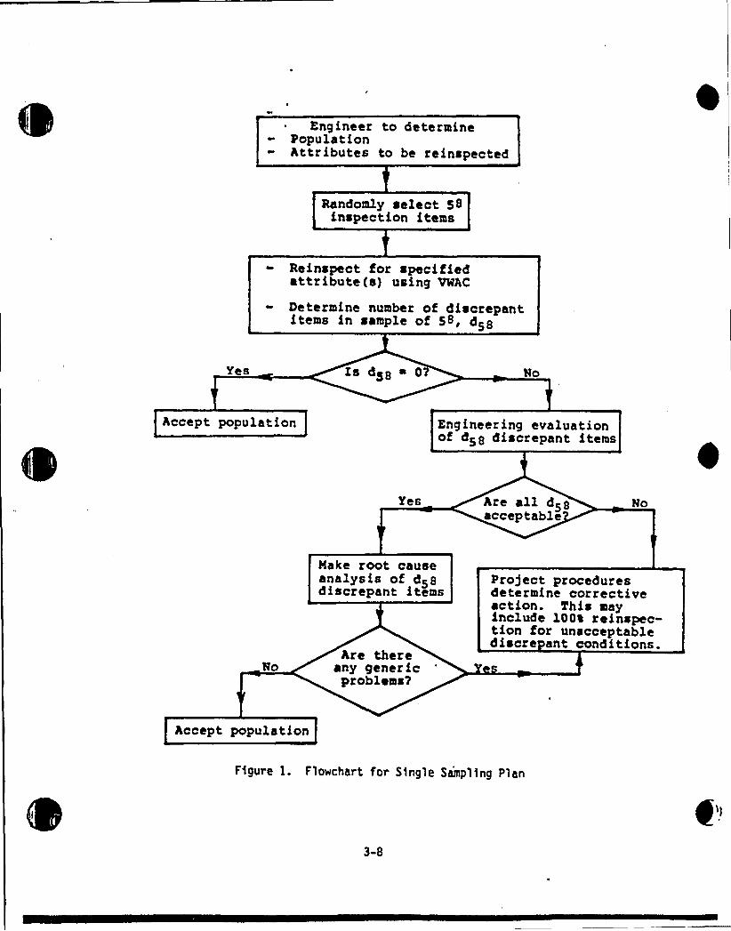
The flowchart forethis sampling plan is given 1n Figure 1. The sample size n
equals 58. The corresponding acceptance and rejection numbers are a58 0 and
r58 I, respectively. The steps of the procedure are as follows.
~Ste t. From the spectrted populatton of stze N, select 58 tnspectton stems atrandom.
3-2
~5te 3 heinspect the selected inspection 1tems for spec1f led attribute(s) using
the acceptance criteria of VNC. For each 1nspection 1tem which is considered0
inaccessible for reinspection, another randomly selected alternative 1tem shall be
substituted 1n the sample. The number of discrepant 1tems 1n th1s sample of 58 is
identified as d58.
~Ste 3s Compare the number of discrepant items dgg to the acceptance number zero.
a) If the number of d1screpant 1tems 1s zero, stop sampl1ng and accept the
popul ation.
b) If the number of discrepant items d58 is one or more, an evaluat1on of
d1screpancies as described in Step 4 1s necessary before population
acceptability can be determined.
~5te 4. Oetensine population acceptability by evaluating observed d1screpancies.
a) If all d58 discrepancies are evaluated as acceptable and 1f a root cause
analysis of these discrepanc1es does not indicate any generic problems,
the population is accepted.
b) If any of the d58 d1screpancies fa11 engineering evaluation or 1f any
generic problems are indicated by the root cause analysis of
discrepancies, the population cannot be accepted on the basis of the
present sampl1ng reinspect1on. Appropriate corrective action shall be
determined using Project Procedures. This may 1nclude IOOX reinspectionfor unacceptable d1screpant conditions and repair or evaluation on a
case-by-case basis. If the root cause is determined to affect only a
small port1on of the or1ginal population, 100% reinspection may be
limited to th1s portion of the populat1on.
3.4 PROCEOURE FOR MULTIPLE SAMPLING PLAN
This is a three-stage sampling plan. The cumulative sample s1ze at each stage and
the corresponding acceptance/rejection numbers are given 1n Table 1. Figure 2
exhibits the flowchart of the plan. The steps of the procedure are as follows.
3-3
~Ste I. Identify 64 lnspect1on 1tems randomly selected from the populat1on ofsize N. This process represents a Stage I sample in Table I where n 64 and
values of acceptance/refection numbers are a64 0/r64 3, respectively.
S~te 2. Reinspect the selected Inspection 1tems for speclf led attribute(s) us1ng
the acceptance criteria of VKAC. For each inspection Item which is cons1dered
inaccessible for reinspection, another randomly selected alternat1ve item shall be
subst1tuted 1n the sample. The number of discrepant items observed 1n the f1rstsample of size 64 1s designated d64.
4
~Ste 3. Compare the number of discrepant 1tems d64 to the acceptance and
re5ection numbers (0, 3) applicable to the first stage 1n Table I'.
a) If the number of discrepant 1tems d64 1s equal to zero, stop sampling and
accept the population.
b) If the number of d1screpant items d64 1s one or two, take one of thefollowing actions:
(i) Continue sampling by going to Step 5.
(11) Stop sampling and determine populat1on acceptability by evaluatingfound discrepancies as described in Step 4.
c) If the number of discrepant items d64 1s three or more, determine
population acceptability by evaluating found discrepancies as describedin Step 4.
~Ste 4. Determine population acceptab111ty by evaluating d64 observed
d1screpancies.
a) If the eng1neering evaluat1on of d64 discrepancies finds all of them
acceptable and if a root cause analysis of these discrepancies does not1ndicate any generic problems, the population 1s accepted.
b) If any of the d64 discrepancies fa11 engineering evaluation or 1f any
generic problems are indicated by the root cause analysis of d64discrepancies, the populat1on cannot be accepted on the basis of presentsampling reinspection. Proceed to Step 9.
3-4
III
lq
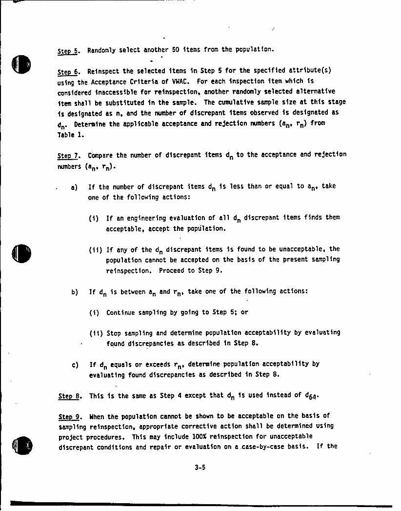
S. Randomly select another 60 items from the population.
~Ste 6. Reinspect the selected items in Step 6 for the specified attribute(s)
using the Acceptance Criter1a of VWAC~ For each inspection item which is
considered inaccessible for re1nspection, another randomly selected alternative
1tem shall be substituted in the sample. The cumulative sample size at this stage
is designated as n, and the number of discrepant items observed is designated as
dn. Oetermine the applicable acceptance and rejection numbers (an, rn) from
Table 1.
~Ste 7. Compare the number of discrepant items d„ to the acceptance and redaction
numbers (anan)')
If the number of d1screpant 1tems dn is less than or equal to an, take
one of the following actions:
(1) If an engineer1ng evaluation of all dn discrepant 1tems f1nds them
acceptable, accept the population.
(11) If any of the dn discrepant items is found to be unacceptable, the
population cannot be accepted on the basis of the present sampling
re1nspection. Proceed to Step 9.
b) If dn 1s between an and rn, take one of the following act1ons:
(1) Continue sampling by going to Step 5; or
(ii) Stop sampl1ng and determine populat1on acceptabil1ty by evaluating
found discrepancies as descr1bed 1n Step 8.
c) If dn equals or exceeds rn, determine population acceptability by
evaluat1ng found discrepancies as described 1n Step 8.
~Ste 8. This is the same as Step a except that d„ is used instead of dda.
~Ste 9 N.hen the population cannot be shown to be acceptable on the basis of
sampl1ng reinspection, appropriate corrective action shall be determined using
project procedures. Th1s may 1nclude IOOL reinspection for unacceptable
d1screpant conditions and repa1r or evaluation on a.case-by-case basis. If the
3-5
root cause $ s determined to affect only a small portion of the originalpopulation, 100K reinspection may be 11mfted to this portion of the populat1on.
3-6
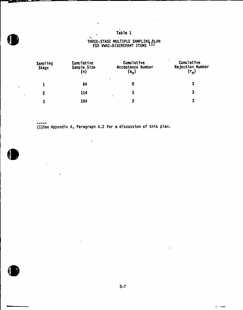
Table 1
THREE-STAGE MULTIPLE SAHPLIHQ, (LANFOR VWAC-DISCREPAHT ITEHS L )
Sampl 3ngStage
CumulativeSample Size
(n)
Cumul at1veAcceptance Humber
(an)
CumulativeRe5ectkon Humber
(rn)
114
164
(1)See Appendix A, Paragraph A.2 for a discussion of th$ s plan.
3-7
Eng ineer to determinePopulationAttributes to be reinspected
Randomly select 58inspection items
Reinspect for specifiedattribute(s) using VWAC
Determine number of discrepantitems in sample of 58/ d58
Yes Is dg8 ~ 02
Accept population Engineering evaluationof d58 discrepant items
Yes Are al) d 5acceptableNo
No
Make root causeanalysis of d58discrepant items
Are thereany genericproblems2
Project proceduresdetermine corrective~ction. This anyinclude 100% reinspec-tion for unacceptablediscre ant conditions.
Accept population
Figure 1. Flowchart for S1ngle Sampling Plan
3-8
i ~
I
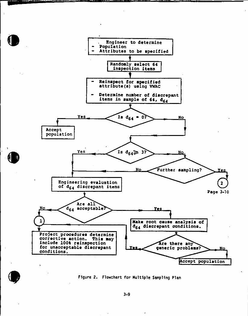
Engineer to determinePopulationAttributes to be specified
Randomly select 64ins ction items
Reinspect for specifiedattribute (s) using VWAC
Determine number of discrepantitems in sample of 64, d64
Yes Zs d64 0 No
Acceptpopulation
Yes Zs d64W~ 3?
Further sampling?
Engineering evaluationof d64 discrepant items
Page 3-10
Are alld64 acceptable
Pro)ect procedures determinecorrective action. This mayinclude 100% reinspectionfor unacceptable discrepantconditions.
Nake root cause analysis ofd64 discrepant conditions.
re there anygeneric problems?
ccept population
F)gure 2. Flowchart for Multiple Sampl)ng Plan
3-9
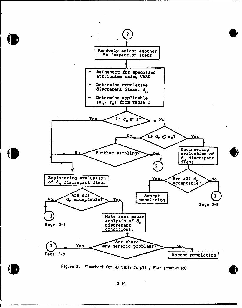
Randomly select another50 inspection items
Reinspect for specifiedattributes using V%AC
Determine cumulativediscrepant items, d„Determine applicable(an, rn) from Table 1
Y s Is dn~ 3?
Is dn W an? Yes
Further samplingEngineeringevaluation ofd discrepanti9ems
Engineering evaluationof d„ discrepant items
Are all dnacceptable?
No
NAre all
d„ acceptable YesAccept
populationPage 3-9
Page 3-9
Nake root causeanalysis of dndiscrepantconditions.
Page 3-9
YesAre there
any generic problems
Accept population
Figure 2. Flowchart for Hultfple Sampling Plan (cont1nued)
3-10
Appendix A
COMHEHTARY
A. 1 General Coaeents on Sampling Plan Implementation
A.2 Parameters of Reconmended Sampling Plans
A.3 Comnents on Treatment of inaccessible ?tems
A.4 Sampling Plan Oocumentation
Q['
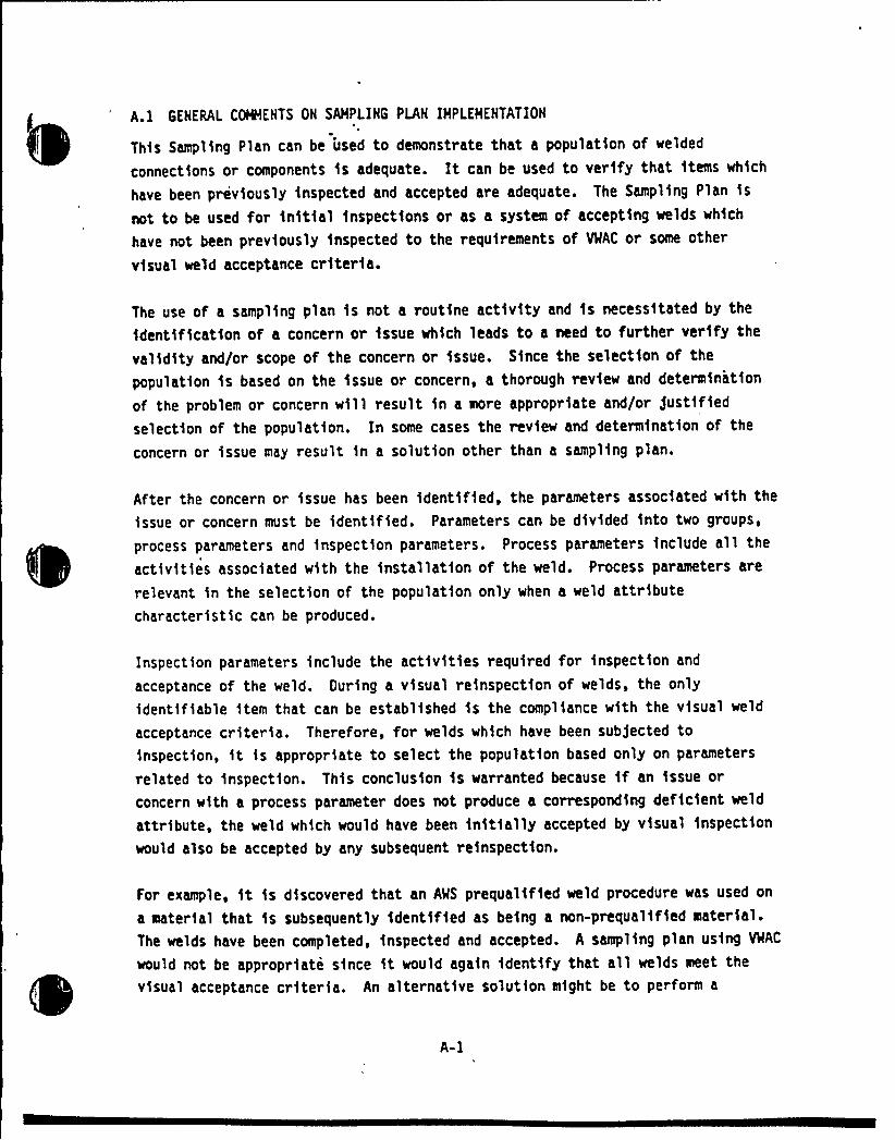
A.l GENERAL COHHENTS OH SAMPLIHG PLAN IMPLEMENTATION'
This Sampling Plan can be used to demonstrate that a population of welded
connect1ons or components is adequate. It can be used to verify that 1tems which
have been previously inspected and accepted are adequate. The Sampling Plan 1s
not to be used for initial inspections or as a system of accepting welds wh1ch
have not been previously 1nspected to the requirements of VWAC or some other
visual weld acceptance criteria.
The use of a sampling plan is not a routine activ1ty and is necess1tated by the
identification of a concern or 1ssue which leads to a need to further verify the
validity and/or scope of the concern or issue. Since the selection of the
populat1on 1s based on the 1ssue or concern, a thorough rev1ew and determination
of the problem or concern will result in a more appropriate and/or just1fiedselection of the populat1on. In some cases the review and determination of the
concern or issue may result 1n a solution other than a sampl1ng plan.
After the concern or issue has been ident1f1ed, the parameters associated w1th the
issue or concern must be identified. Parameters can be divided into two groups,
process parameters and inspection parameters. Process parameters 1nclude all the
act1vit1es associated w1th the 1nstallat1on of the weld. Process parameters are
relevant in the selection of the populat1on only when a weld attributecharacteristic can be produced.
Inspection parameters include the activities required for inspection and
acceptance of the weld. Ouring a v1sual reinspection of welds, the onlyidentifiable 1tem that can be established is the compliance with the visual weld
acceptance cr1teria. Therefore, for welds which have been subjected to1nspection, it is appropriate to select the population based only on parameters
related to inspect1on. This conclus1on 1s warranted because 1f an 1ssue or
concern with a process parameter does not produce a corresponding deficient weld
attribute, the weld wh1ch would have been init1ally accepted by v1sual inspection
would also be accepted by any subsequent re1nspect1on.
For example, 1t is discovered that an A'KS prequalified weld procedure was used on
a material that 1s subsequently ident1fied as being a non-prequal1fied material.The welds have been completed, 1nspected and accepted. A sampling plan using VMAC
would not be appropr1ate s1nce 1t would aga1n 1dent1fy that all welds meet the
visual acceptance criteria. An alternative solution might be to perform a
A-I
procedure qual1fication test on the new material using the same essent1al
variables of the weld procedure and then disposition the issue based on the testresults.
Nen inspection parameters are a concern or issue, it 1s appropriate to cons1der
both the inspection and process criteria parameters in select1on the population.The Engineer shall 1dentify for the reinspection the appropr1ate weld attr1bute(s)which could ex1st as a result of the initial concern or issue.
For example, in a situation w1th numerous concerns related to both process and
inspection parameters, the Engineer may 1dentify all the weld attributes forreinspection. To cover all the associated process and inspection parameters, theEng1neer could elect to select the populat1on based on types of structures, i.e.,structural steel, p1pe hangers, electr1cal supports, HVAC supports, etc. In thistype situation, 1t may be appropr1ate for the HRC to review the sampling planprogram prior to 1nitiat1on.
Inspection parameters affecting populat1on may include:
l. Organization Inspection the fields
Inspect1on organizations are 11kely to vary 1n 1nspectortra1ning, inspect1on documentation methods, degree ofsupervision and the educational background and/or experience of1ts inspectors.
2. Inspection Procedure
Inspection procedures may be plant w1de, may vary fromorganizat1on to organization, may vary with the type of work(electr1cal, mechn1cal, civ11/structural) and may vary 1n thetype of welding (submerged arc, s111con bronze, etc.)
3. Shop Versus F1eld fields
Unless 1t can be shown that the same 1nspection procedures wereutilized by a particular organization under s1milar conditionsfor both shop and f1eld welds, populations should not combineshop and field welds.
4. Inspector
The individual inspector's ability and performance of hisdut1es to the established requirements is a parameter. Itemsto consider are training, qual1fication, and his compliancewith the requirements.
A-2
Process parameters affecting population selection may include:
2.
Organizat1on Haking Welds
Oifferent contractors are 11kely to have d1fferences 1n weldertraining, degree of supervis1on and work documentation methods.
Type of Structure and Craft
The different types of structures (i.e., structural steel, pipehangers, electrical supports, or HVAC supports) at nuclearpower plants require several different construction crafts(i.e., iron workers, pipe f1tters, boiler makers,electr1cians). These d1fferent construction crafts may beemployed by a s1ngle general contractor. Therefore, the typeof structure and craft should be evaluated to determine theappropriate representative parameters to be used in def1ningthe populat1on.
3. We 1 ding Procedures
Welding procedures have a sign1ficant bearing on the nature ofthe finished weld. Therefore, 1t is important to identify theweld procedures wh1ch are representat1ve of the 1n1tial 1ssueor concern. For example, some 1tems for consideration inselecting the weld procedure are type of product, size, type ofjo1nt, position, and other essential variables. Althoughprocedures may undergo revisions during the course of aproject, only significant procedural changes could warrantconsideration of an additional sample. Since contractorsgenerally work to their own weld procedures, it is likely thata population can be defined according to the contractor whoperformed the work. If, on the other hand, severalsubcontractors were involved 1n similar work in which astandard prequalified AMS welding procedure was used, thepopulation would not necessarily need to be divided among thesubcontractors.
4. Shop Versus Field Welds
Unless it can be shown that the same welding procedures andtechniques wer e util1zed by a particular organization undersimilar conditions for both shop and field welds, populationshould not combine work done in both the shop and field.
5. Welder
The ind1v1dual welder's ab111ty and performance of his dut1esto the established requirements is a parameter for def1ning apopulation. Items to be considered are training, qualificat1onand his compliance with the requirements.
A general parameter that must always be considered is the t1me period for the1dentified issue or concern. It 1s essential that the population selected be
representative of the appropriate time period of the welding or inspection. If
A-3
the time period can not be defined, the Engineer should select the populat1on toencompass the concern or. issue.
Mhen the Engineer performs an engineering evaluation of the observeddiscrepanc1es, it is permissible to use:
1. Allowable stresses based on specified, actual or representativephysical properties.
2. Specified or actual loads.
3. Nore refined stress analysis.
A.2 PARAMETERS OF RECOMMEKOED SAMPLIKG PLAKS
The operating character1stic curve of each of the single and multiple samplingplans 1s shown 1n Figure Al. The population percent discrepant 1n F1gure Alrefers to VWAC discrepancies. If a population has SX VNAC discrepancies,Figure Al shows that the probability of this population being accepted by thesingle sampl1ng plan is 5.1X. The corresponding value for the multiple samplingplan is 5.04K. Therefore, both plans at reliability of 95K provide nearly 95Kconfidence; they are 95/95 plans for acceptance using %AC without furtherengineer1ng evaluation. The curve for the s1ngle sampling plan in Figure Al alsoshows that for percent discrepant values smaller than 5% (higher values ofreliability), the single sampling plan is more conservative. This means that themultiple plan has a higher probab111ty of accepting the population.
When eng1neering evaluation is used to accept the populat1on using samplingresults, percent discrepant will refer to its fa1lure to meet engineeringevaluation. The sampl1ng procedures in this document have a zero discrepantacceptable condition for this type of d1screpancy. This means that whether thesingle or multiple plan is used, every discrepancy found must be acceptablethrough engineering evaluation before the population is accepted. The operatingcharacteristic curve for the single sampling plan in this case is again the same
as the one shown in Figure A.l. Mhen the multiple plan is used, the sample "sizeat wh1ch engineer1ng evaluat1on is made could be either 64, 114, or 164. For thisreason, the construction of the operating characteristic curve for this case isnot directly available. However, since the sample size w1ll be at least 64 and a
zero discrepant acceptable condition is being used, the operating characteristiccurve for this use of the multiple plan procedure should be more conservative thanfor the single plan. Consequently, the use of the multiple plan will provide
A-4
better than 95K reliability at 95K'confidence when an engineering evaluation isused.
A.3 CONEHTS ON TREATMENT OF INACCESSIBLE ITEMS
Step 2 in Paragraph 3.3 describing implementation of a s1ngle plan, and Steps 2
and 6 1n Paragraph 3.4 for a mltiple plan permit the use of a randomly selected
alternative when the init1ally selected item 1s not physically access1ble due toreasons determined as acceptable by the Engineer. Th1s should not introduce bias
1n sampl1ng when concerns which led to the decision of performing sampling are not
related to inaccess1bility.
A.4 SAMPLIHG PLAN DOCUMENTATION
This sampl1ng plan is considered a design activity for the purpose of accept1ng a
weld populat1on. Sufficient documentation should be developed such that a person
technically qualified can review and understand the applicat1on, implementation
and results of the sampl1ng plan without recourse to the originator.
Documentation should address but not be 11m1ted to the following sampl1ng planactivities:
l. A descr1ption of the concern(s) or 1ssue(s).
2. Identification of parameters and select1on of thepopulation(s).
3. Generat1on and identification of random 1nspection items.
4. Criteria for defining and treat1ng inaccessible items.
5. Inspection procedure and acceptance cr i teria.
6. Select1on of the single or eel tiple sampl1ng plan.
7. Results of reinspect1ons and a review of the valid1ty ofassumptions made in defin1ng the population.
8. Results of any engineering evaluations.
9. Any root cause analysts of discrepent items.
10. Results and/or conclusions.
Design control measures shall be applied to verify the adequacy of the sampling
evaluat1on. Management shall be 1nformed of the intent, act1vities and results ofa sampling plan effort.
A-5
e

I.O
0.9
~gy O.b
hlo 0.7z
~ 08oo
006O
I- OA
~) 0.3
0.2
O. I
PI- ZERO-OISCRPANT ACCEPTABLESlveLK a,AII (n *5e)
P2- THREE-STAGE MULTIPLE PLANOF TABLE I.
0'OSI FOR PI
$ 0504 FOR P2
0 I 2 3 4 5 6
PERCENT VWAC 01SCREPANT, p
Figure A-1. Operating Characteristic Curves for Recomnended Single and Multiple Plans
Appendix B
NRC LETTER ACCEPTING SAMPLING PLAN FOR VISUAL REINSPECTION OF TELOS(NCIG-02, Revksfon 2)

zr
gP +((i(((
«gl 0
y)~ 0 ~ ~ 0
UNITED STATESNUCLEAR REGULATORY COMMISSION
IVASHIHCTON.0, C. 205S5
APR 09 NP
Mr. Malter H. Meber, ChairmanNuclear Construction Issues 6roupVnfon Electric Company2815 Scott AvenueSt. Louis, MO 63103
Dear Mr. 'Mcber:
SUBJECT: 'Sampling Plan For Visual Reinspection of Melds"(NCIG-02) Revision 2
REFERENCE: Letters from R. A. Thomas to R. J. 8osnak,dated March 18, 1987 and March 25, 1987
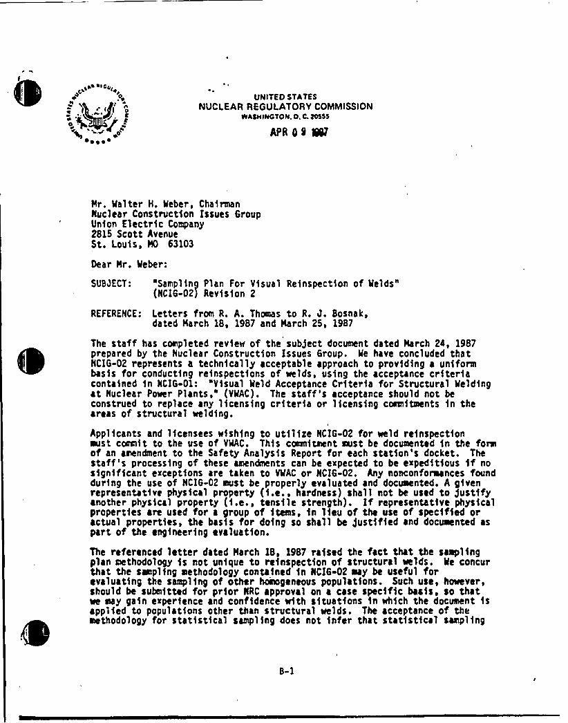
The staff has completed review of the sub)ect document dated March 24, 1987prepared by the Nuclear Construction Issues 6roup. Me have concluded thatNCIG-02 represents a technically acceptable approach to providing a uniformbasfs for conducting refnspectfons of wclds, using the acceptance criteriacontafned fn NCIG-01: "Visual Meld Acceptance Criteria for Structural 'Meldingat Nuclear Power Plants," (VMAC). The staff's acceptance should not beconstrued to replace any licensing criteria or licensing coaeftacnts fn theareas of structural wcldfng.
Applicants and licensees wishing to utilize NCIG-02 for weld reinspectionest coamIit to the use of VMAC. This coanftaent east be documented fn the foraof an aaendmcnt to the Safety Analysis Rcport for each station's docket. Thestaff 's processing of these amendments can be expected to bc expeditious ff nosignificant exceptions are taken to VMAC or NCIG-02. Any nonconforaances foundduring the use of NCIG-02 aust be properly evaluated and docuaented. A givenrepresentative physfcal property (f.e., hardness) shall not be used to gustffyanother physical property (f.e., tensile strength). If representative physicalpropertfes are used for a group of items, fn lieu of the use of specified oractual properties, the basis for doing so shall be )ustified and docuaented aspart of the engineering evaluation.
The referenced letter dated March 18, 1987 raised the fact that the samplingplan methodology fs not unique to reinspection of structural welds. Ke concurthat the sapling methodology contained fn NCI6-02 say be useful forevaluating the sampling of other hoinogeneous populations. Such use, however,should bc submitted for prior KRC approval on a case specific bacfs. so thatwe may gain experience and confidence with situations fn which the document fsapplied to populations other than structural welds. The acceptance of themethodology for statistical sampling does not infer that statistical sampling
B-1
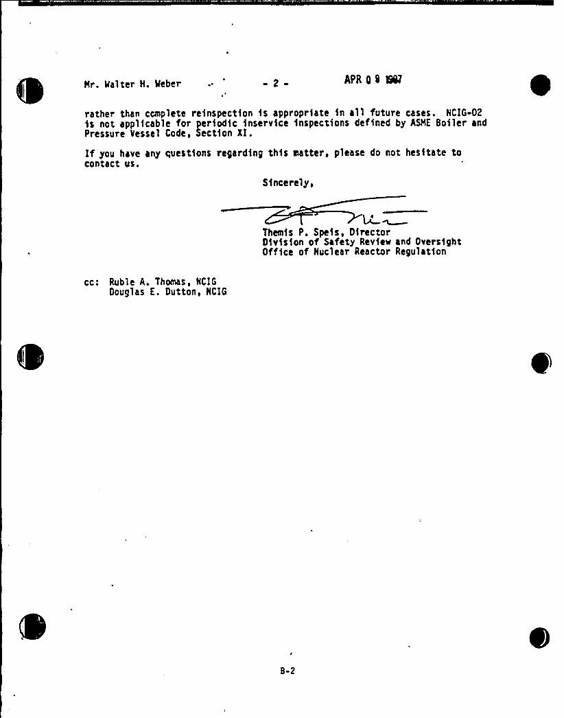
Hr. 'Halter H. Heber 2 a APR 0 Q SN
rather than complete reinspection is appropriate in all future cases. HCIG-02is not applicable for periodic inservice inspections defined by ASHE Boiler andPressure Vessel Code, Section XI.
If you have any questions regarding this Natter, please do not hesitate tocontact us.
Sincerely,
W ~Themis P. Speis, DirectorDivision of Safety Review and OversightOffice of Huclear Reactor Regulation
cc: Ruble A. Thomas, HCIGDouglas E. Dutton, HCIG
B-2


Enclosure 3
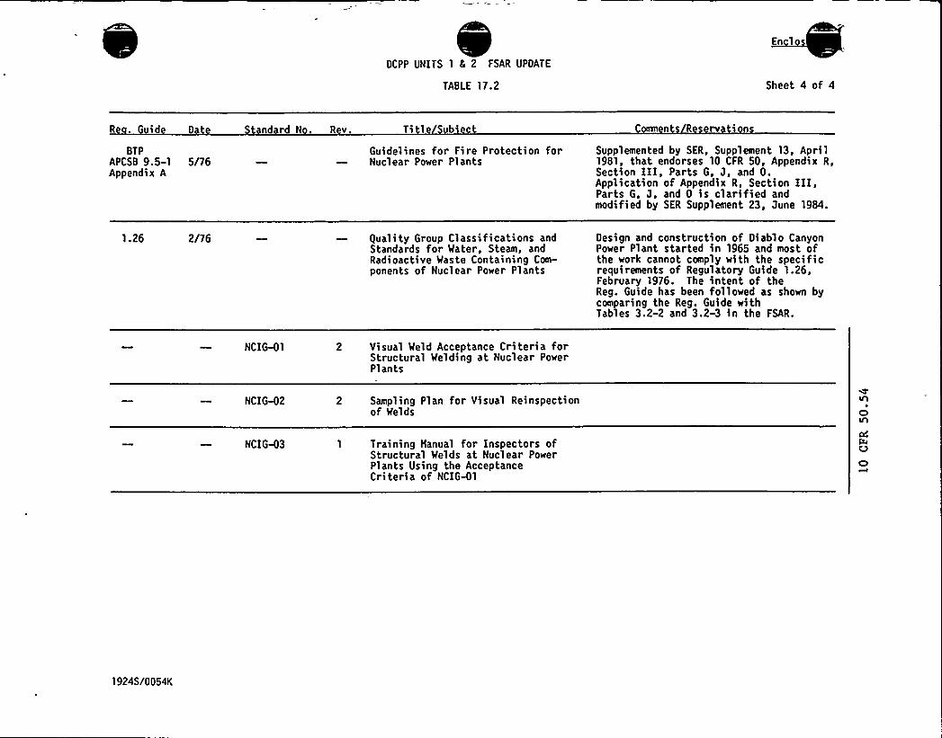
OCPP UNITS 1 & 2 FSAR UPOATE
TABLE 17.2
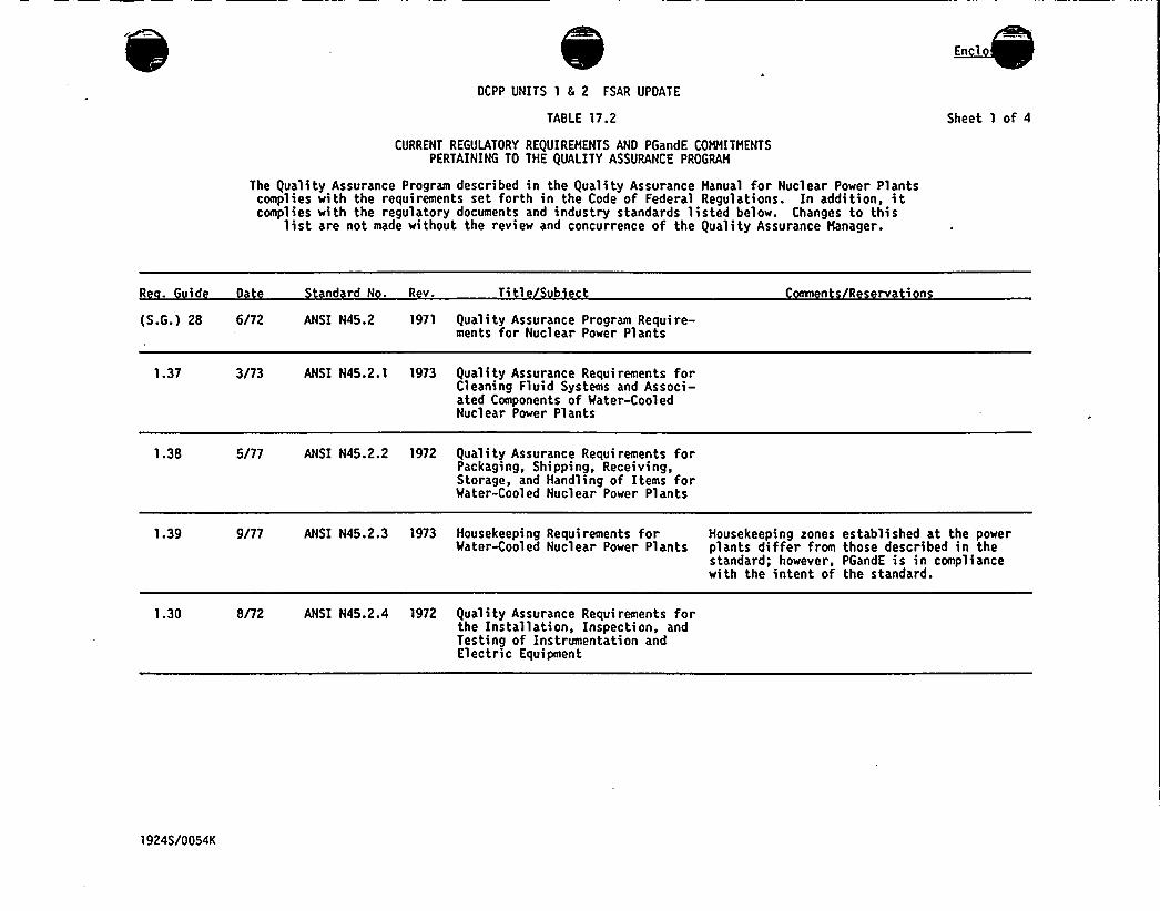
CURRENT REGULATORY REQUIREHENTS ANO PGandE COHHITHENTSPERTAINING TO THE QUALITY ASSURANCE PROGRAH
The Quality Assurance Program described in the Quality Assurance Hanual for Nuclear Power Plantscomplies with the requirements set forth in the Code of Federal Regulations. In addition, itcomplies with the regulatory documents and industry standards listed below. Changes to this
list are not made without the revie~ and concurrence of the Quality Assurance Hanager.
Sheet 1 of 4
R . id 0 nd rd N . R v. Ti 1 b n R rv in(S.G.) 28 6/72 ANSI N45.2 1971 Qual i ty Assurance Program Require-
ments for Nuclear Power Plants
1.37 3/73 ANSI N45.2.1 1973 Quali ty Assurance Requirements forCleaning Fluid Systems and Associ-ated Components of Mater-CooledNuclear Power Plants
1.38 5/77 ANSI N45.2.2 1972 Quality Assurance Requirements forPackaging, Shipping, Receiving,Storage, and Handling of Items forMater-Cooled Nuclear Power Plants
1.39 9/77 ANSI N45.2.3 1973 Housekeeping Requirements for Housekeeping zones established at the powerMaterCooled Nuclear Power Plants plants differ from those described in the
standard; however, PGandE is in compliancewith the intent of the standard.
1.30 8/72 ANSI N45.2.4 1972 Quality Assurance Requirements forthe Installation, Inspection, andTesting of Instrumentation andElectric Equipment
19245/0054K
DCPP UNITS 1 5 FSAR UPDATE
TABLE 17.2
En 1
Sheet 2 of 4
R . uid D nd rd N . R v. Ti 1 b eann R rv i n
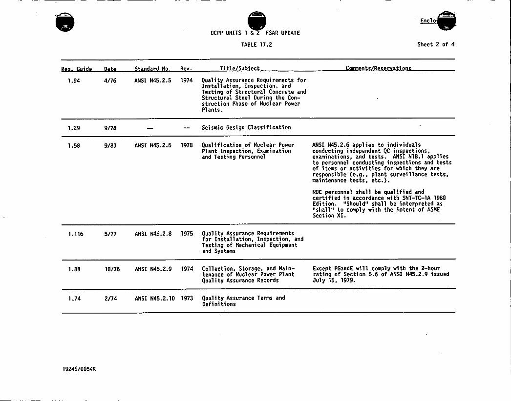
1.94 4/76 ANSI N45.2.5 1974 guali ty Assurance Requirements forInstallation, Inspection, andTesting of Structural Concrete andStructural Steel During the Con-struction Phase of Nuclear PowerPlants.
1.29 9/78 Seismic Design Classification
1.58 9/80 ANSI N45.2.6 1978 gualification of Nuclear PowerPlant Inspection, Examinationand Testing Personnel
ANSI N45.2.6 applies to individualsconducting independent gC inspections,examinations, and tests. ANSI N18.1 appliesto personnel conducting inspections and testsof items or activities for which they areresponsible (e.g., plant surveillance tests,maintenance tests, etc.).
NDE personnel shall be qualified andcertified in accordance with SNT-TC-lA 1980Edition. "Should" shall be interpreted as"shall" to comply with the intent of ASHESection XI.
1.116 5/77 ANSI N45.2.8 1975 guali ty Assurance Requirementsfor Installation, Inspection, andTesting oF Hechanical Equipmentand Systems
1.88 10/76 ANSI N45.2.9 1974 Collection, Storage, and Hain- Except PGandE will comply with the 2-hourtenance of Nuclear Power Plant rating of Section 5.6 of ANSI N45.2.9 issuedguality Assurance Records July 15, 1979.
1.74 2/74 ANSI N45.2.10 1973 guali ty Assurance Terms andDefinitions
1924S/0054K
DCPP UNITS 1 5 2 FSAR UPDATE
TABLE 17.2
En 1
Sheet 3 of 4
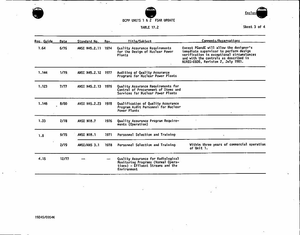
R - id 0 ndrdN. Rv. Ti 1 b n R rv in1.64 6/76 ANSI N45.2. 11 1974 Quality Assurance Requirements
for the Design of Nuclear PowerPlants
Except PGandE will allow the designer'siamediate supervisor to perform designverification in exceptional circumstancesand with the controls as described inNUREG-0800, Revision 2, July 1981.
1.144 1/79. ANSI N45.2.12 1977 Audi ting of (}uality AssurancePiograms for Nuclear Power Plants
1.123 7/77 ANSI N45.2.13 1976 Quality Assurance Requirements forControl of Procurement of Items andServices for Nuclear Power Plants
1.146 8/80 ANSI N45.2.23 1978 qualification of ()uality AssuranceProgram Audit Personnel for NuclearPower Plants
1.33 2/78 ANSI N18.7 1976 guali ty Assurance Program Require-ments (Operation)
1.8 9/75 ANSI N18.1 1971 Personnel Selection and Training
2/79 ANSI/ANS 3.1 1978 Personnel Selection and Training Mithin three years of coamercial operationof Unit 1.
4.15 12/77 guali ty Assurance for RadiologicalMonitoring Programs (Normal Opera-tions) - EfFluent Streams and theEnvironment
1924S/0054K

0
En lo
OCPP UNITS 1 5 2 FSAR UPDATE
TABLE 17.2 Sheet 4 of 4
R . id 0
BTPAPCSB 9.5-1 5/76Appendix A
ndrdN. Rv. Ti 1 b
Guidelines for Fire Protection forNuclear Power Plants
n R rv inSupplemented by SER, Supplement 13, April1981, that endorses 10 CFR 50, Appendix R,Section III, Parts G, J, and 0.Application of Appendix R, Section III,Parts G, J, and 0 is clarified andmodified by SER Supplement 23, June 1984.
1.26 2/76 guality Group Classifications andStandards for Mater, Steam, andRadioactive Waste Containing Com-ponents of Nuclear Power Plants
Oesign and construction of Oiablo CanyonPower Plant started in 1965 and most ofthe work cannot comply with the specificrequirements of Regulatory Guide 1.26,February 1976. The intent of theReg. Guide has been followed as shown bycomparing the Reg. Guide withTables 3.2-2 and 3.2-3 in the FSAR.
NCIG-01 2 Visual Meld Acceptance Criteria forStructural Melding at Nuclear PowerPlants
NCIG-02 2 Sampling Plan for Visual Reinspectionof Melds
NCIG-03 1 Training Manual for Inspectors ofStructural Melds at Nuclear PowerPlants Using the AcceptanceCriteria of NCIG-01
1924S/0054K
4
~ r 0
0