virtualized reconfigurable resources and their secured ... · virtualized reconfigurable resources...
TRANSCRIPT
Faculty of Computer Science Institute of Computer Engineering, Chair of VLSI EDA
Diploma Thesis
Virtualized Reconfigurable Resourcesand Their Secured Provision in anUntrusted Cloud Environment
Paul R. GenßlerBorn on: 26.05.1990 in BerlinMatriculation number: 3569856Matriculation year: 2009
to achieve the academic degree
Diplom-Informatiker (Dipl.-Inf.)
First referee
Prof. Dr.-Ing. habil. Rainer G. SpallekSecond referee
Prof. Dr.-Ing. Diana GöhringerSupervisor
Dipl.-Inf. Oliver Knodel
Submitted on: 20.11.2017

Statement of authorship
I hereby certify that I have authored this Diploma Thesis entitled Virtualized Reconfigurable Re-sources and Their Secured Provision in an Untrusted Cloud Environment independently andwithout undue assistance from third parties. No other than the resources and references indi-cated in this thesis have been used. I have marked both literal and accordingly adopted quota-tions as such. There were no additional persons involved in the intellectual preparation of thepresent thesis. I am aware that violations of this declaration may lead to subsequent withdrawalof the degree.
Dresden, 20.11.2017
Paul R. Genßler


Abstract
The cloud computing business grows year after year. To keep up with increasing demand and tooffer more services, data center providers are always searching for novel architectures. One ofthem are FPGAs, reconfigurable hardware with high compute power and energy efficiency. Butsome clients cannot make use of the remote processing capabilities. Not every involved partyis trustworthy and the complex management software has potential security flaws. Hence,clients’ sensitive data or algorithms cannot be sufficiently protected.
In this thesis state-of-the-art hardware, cloud and security concepts are analyzed and com-bined. On one side are reconfigurable virtual FPGAs. They are a flexible resource and fulfillthe cloud characteristics at the price of security. But on the other side is a strong requirementfor said security. To provide it, an immutable controller is embedded enabling a direct, confi-dential and secure transfer of clients’ configurations. This establishes a trustworthy computespace inside an untrusted cloud environment. Clients can securely transfer their sensitive dataand algorithms without involving vulnerable software or a data center provider. This concept isimplemented as a prototype. Based on it, necessary changes to current FPGAs are analyzed.To fully enable reconfigurable yet secure hardware in the cloud, a new hybrid architecture isrequired.
Zusammenfassung
Das Geschäft mit dem Cloud Computing wächst Jahr für Jahr. Um mit der steigenden Nach-frage mitzuhalten und neue Angebote zu bieten, sind Betreiber von Rechenzentren immer aufder Suche nach neuen Architekturen. Eine davon sind FPGAs, rekonfigurierbare Hardware mithoher Rechenleistung und Energieeffizienz. Aber manche Kunden können die ausgelagertenRechenkapazitäten nicht nutzen. Nicht alle Beteiligten sind vertrauenswürdig und die komple-xe Verwaltungssoftware ist anfällig für Sicherheitslücken. Daher können die sensiblen Datendieser Kunden nicht ausreichend geschützt werden.
In dieser Arbeit werden modernste Hardware, Cloud und Sicherheitskonzept analysiert undkombiniert. Auf der einen Seite sind virtuelle FPGAs. Sie sind eine flexible Ressource und ha-ben Cloud Charakteristiken zum Preis der Sicherheit. Aber auf der anderen Seite steht ein ho-hes Sicherheitsbedürfnis. Um dieses zu bieten ist ein unveränderlicher Controller eingebettetund ermöglicht eine direkte, vertrauliche und sichere Übertragung der Konfigurationen der Kun-den. Das etabliert eine vertrauenswürdige Rechenumgebung in einer nicht vertrauenswürdigenCloud Umgebung. Kunden können sicher ihre sensiblen Daten und Algorithmen übertragen oh-ne verwundbare Software zu nutzen oder den Betreiber des Rechenzentrums einzubeziehen.Dieses Konzept ist als Prototyp implementiert. Darauf basierend werden nötige Änderungenvon modernen FPGAs analysiert. Um in vollem Umfang eine rekonfigurierbare aber dennochsichere Hardware in der Cloud zu ermöglichen, wird eine neue hybride Architektur benötigt.

Contents
Abstract/Zusammenfassung I
List of Figures VII
List of Tables IX
List of Acronyms X
1 Introduction 1
2 Background and Related Work 32.1 Background . . . . . . . . . . . . . . . . . . . . . . . . . . . . . . . . . . . . . . 3
2.1.1 Symmetric Cryptography . . . . . . . . . . . . . . . . . . . . . . . . . . 42.1.1.1 Advanced Encryption Standard . . . . . . . . . . . . . . . . . . 42.1.1.2 Other Symmetric Encryption Algorithms . . . . . . . . . . . . 52.1.1.3 Comparison of Symmetric Cryptographic Systems . . . . . . . 6
2.1.2 Asymmetric Cryptography . . . . . . . . . . . . . . . . . . . . . . . . . . 62.1.2.1 RSA Cryptosystem . . . . . . . . . . . . . . . . . . . . . . . . 62.1.2.2 Elliptic Curve Cryptography . . . . . . . . . . . . . . . . . . . . 82.1.2.3 Comparison of Asymmetric Cryptographic Systems . . . . . . 102.1.2.4 Diffie-Hellman Key Exchange . . . . . . . . . . . . . . . . . . . 10
2.1.3 Digital Signatures . . . . . . . . . . . . . . . . . . . . . . . . . . . . . . . 112.1.4 Hash Functions . . . . . . . . . . . . . . . . . . . . . . . . . . . . . . . . 122.1.5 Message Authentication Code . . . . . . . . . . . . . . . . . . . . . . . 132.1.6 Certificates . . . . . . . . . . . . . . . . . . . . . . . . . . . . . . . . . . 152.1.7 TLS Protocol . . . . . . . . . . . . . . . . . . . . . . . . . . . . . . . . . 16
2.2 Related work . . . . . . . . . . . . . . . . . . . . . . . . . . . . . . . . . . . . . 182.2.1 Security Concerns in Cloud Computing . . . . . . . . . . . . . . . . . . 182.2.2 Approaches on Cloud Security . . . . . . . . . . . . . . . . . . . . . . . 182.2.3 Virtual FPGAs for the Cloud . . . . . . . . . . . . . . . . . . . . . . . . . 192.2.4 FPGA Security Concepts . . . . . . . . . . . . . . . . . . . . . . . . . . 202.2.5 Approaches on Security of Remote FPGAs . . . . . . . . . . . . . . . . 21
3 Design 233.1 Threat Model . . . . . . . . . . . . . . . . . . . . . . . . . . . . . . . . . . . . . 233.2 Trust Model . . . . . . . . . . . . . . . . . . . . . . . . . . . . . . . . . . . . . . 24
III
Contents
3.3 Host/FPGA-Hypervisor . . . . . . . . . . . . . . . . . . . . . . . . . . . . . . . . 263.3.1 Initializing a Secure Connection . . . . . . . . . . . . . . . . . . . . . . . 27
3.3.1.1 Data Encryption . . . . . . . . . . . . . . . . . . . . . . . . . . 283.3.1.2 Sharing a Common Secret . . . . . . . . . . . . . . . . . . . . 283.3.1.3 Authenticity of an Accelerator . . . . . . . . . . . . . . . . . . 293.3.1.4 Message Authentication . . . . . . . . . . . . . . . . . . . . . 293.3.1.5 Bitstream Transfer Protocol . . . . . . . . . . . . . . . . . . . . 30
3.3.2 Robust Virtualization of Reconfigurable Logic . . . . . . . . . . . . . . . 313.3.2.1 Limiting the Reconfigurability . . . . . . . . . . . . . . . . . . . 323.3.2.2 Overlapping Resources . . . . . . . . . . . . . . . . . . . . . . 32
3.4 From Design to Hardware . . . . . . . . . . . . . . . . . . . . . . . . . . . . . . 33
4 SecFPGA-Hypervisor Implementation 354.1 EC Key Processor . . . . . . . . . . . . . . . . . . . . . . . . . . . . . . . . . . 36
4.1.1 Elliptic Curve Multiplier . . . . . . . . . . . . . . . . . . . . . . . . . . . 364.1.2 True Random Number Generator . . . . . . . . . . . . . . . . . . . . . . 384.1.3 Key Derivation . . . . . . . . . . . . . . . . . . . . . . . . . . . . . . . . 404.1.4 ECDSA . . . . . . . . . . . . . . . . . . . . . . . . . . . . . . . . . . . . 40
4.2 Command Decoder . . . . . . . . . . . . . . . . . . . . . . . . . . . . . . . . . 424.2.1 Hash . . . . . . . . . . . . . . . . . . . . . . . . . . . . . . . . . . . . . . 424.2.2 Certificate . . . . . . . . . . . . . . . . . . . . . . . . . . . . . . . . . . . 45
4.3 Key Store . . . . . . . . . . . . . . . . . . . . . . . . . . . . . . . . . . . . . . . 454.4 Configuration Filter . . . . . . . . . . . . . . . . . . . . . . . . . . . . . . . . . . 464.5 Encryption Engines . . . . . . . . . . . . . . . . . . . . . . . . . . . . . . . . . . 46
5 Results 495.1 Security Evaluation . . . . . . . . . . . . . . . . . . . . . . . . . . . . . . . . . . 495.2 Deployment Delay . . . . . . . . . . . . . . . . . . . . . . . . . . . . . . . . . . 50
5.2.1 Precomputations for a TLS Handshake . . . . . . . . . . . . . . . . . . . 515.2.2 Computations during a TLS Handshake . . . . . . . . . . . . . . . . . . 52
5.3 Extra Latency Through AES . . . . . . . . . . . . . . . . . . . . . . . . . . . . . 535.4 Resource Utilization of the SecFPGA-Hypervisor . . . . . . . . . . . . . . . . . 55
5.4.1 Resource Utilization of the EC Key Processor . . . . . . . . . . . . . . . 555.4.2 Resource Utilization of the CMD Decoder . . . . . . . . . . . . . . . . . 565.4.3 Resource Utilization of the AES Cores . . . . . . . . . . . . . . . . . . . 565.4.4 Estimated Utilization of an Optimized Implementation . . . . . . . . . . 57
6 Conclusions and Future Work 61
Bibliography XIII
Appendix A-1A SecFPGA-Hypervisor Commands . . . . . . . . . . . . . . . . . . . . . . . . . . A-1B Certificate of a SecFPGA . . . . . . . . . . . . . . . . . . . . . . . . . . . . . . B-1
IV


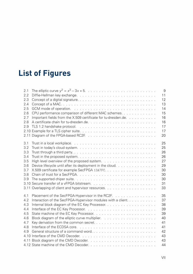
List of Figures
2.1 The elliptic curve y2 = x3 − 3x + 5. . . . . . . . . . . . . . . . . . . . . . . . . . 92.2 Diffie-Hellman key exchange. . . . . . . . . . . . . . . . . . . . . . . . . . . . . 112.3 Concept of a digital signature. . . . . . . . . . . . . . . . . . . . . . . . . . . . . 122.4 Concept of a MAC. . . . . . . . . . . . . . . . . . . . . . . . . . . . . . . . . . . 132.5 GCM mode of operation. . . . . . . . . . . . . . . . . . . . . . . . . . . . . . . 142.6 CPU performance comparison of different MAC schemes. . . . . . . . . . . . . 152.7 Important fields from the X.509 certificate for tu-dresden.de. . . . . . . . . . . 162.8 A certificate chain for tu-dresden.de. . . . . . . . . . . . . . . . . . . . . . . . . 162.9 TLS 1.2 handshake protocol. . . . . . . . . . . . . . . . . . . . . . . . . . . . . 172.10 Example for a TLS cipher suite. . . . . . . . . . . . . . . . . . . . . . . . . . . . 172.11 Diagram of the FPGA-based RC2F. . . . . . . . . . . . . . . . . . . . . . . . . . 20
3.1 Trust in a local workplace. . . . . . . . . . . . . . . . . . . . . . . . . . . . . . . 253.2 Trust in today’s cloud system. . . . . . . . . . . . . . . . . . . . . . . . . . . . . 253.3 Trust through a third party. . . . . . . . . . . . . . . . . . . . . . . . . . . . . . . 263.4 Trust in the proposed system. . . . . . . . . . . . . . . . . . . . . . . . . . . . . 263.5 High level overview of the proposed system. . . . . . . . . . . . . . . . . . . . 273.6 Device lifecycle until after its deployment in the cloud. . . . . . . . . . . . . . . 293.7 X.509 certificate for example SecFPGA 13A7FC. . . . . . . . . . . . . . . . . . . 303.8 Chain of trust for a SecFPGA. . . . . . . . . . . . . . . . . . . . . . . . . . . . . 303.9 The supported chiper suite. . . . . . . . . . . . . . . . . . . . . . . . . . . . . . 303.10 Secure transfer of a vFPGA bitstream. . . . . . . . . . . . . . . . . . . . . . . . 313.11 Overlapping of client and hypervisor resources. . . . . . . . . . . . . . . . . . . 33
4.1 Placement of the SecFPGA-Hypervisor in the RC2F. . . . . . . . . . . . . . . . 354.2 Interaction of the SecFPGA-Hypervisor modules with a client. . . . . . . . . . . 374.3 Internal block diagram of the EC Key Processor. . . . . . . . . . . . . . . . . . . 384.4 Interface of the EC Key Processor. . . . . . . . . . . . . . . . . . . . . . . . . . 394.5 State machine of the EC Key Processor. . . . . . . . . . . . . . . . . . . . . . . 394.6 Block diagram of the elliptic curve multiplier. . . . . . . . . . . . . . . . . . . . 404.7 Key derivation from the common secret. . . . . . . . . . . . . . . . . . . . . . . 414.8 Interface of the ECDSA core. . . . . . . . . . . . . . . . . . . . . . . . . . . . . 414.9 General structure of a command word. . . . . . . . . . . . . . . . . . . . . . . . 424.10 Interface of the CMD Decoder. . . . . . . . . . . . . . . . . . . . . . . . . . . . 434.11 Block diagram of the CMD Decoder. . . . . . . . . . . . . . . . . . . . . . . . . 434.12 State machine of the CMD Decoder. . . . . . . . . . . . . . . . . . . . . . . . . 44
VII
LIST OF FIGURES
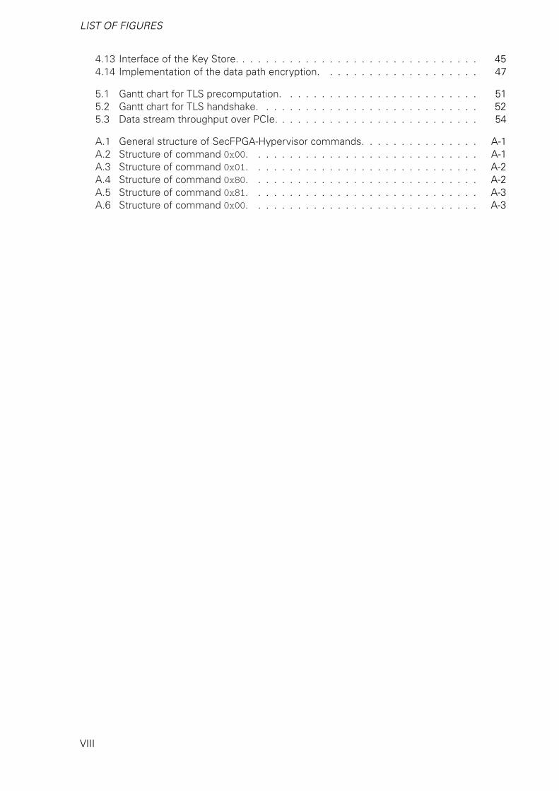
4.13 Interface of the Key Store. . . . . . . . . . . . . . . . . . . . . . . . . . . . . . . 454.14 Implementation of the data path encryption. . . . . . . . . . . . . . . . . . . . 47
5.1 Gantt chart for TLS precomputation. . . . . . . . . . . . . . . . . . . . . . . . . 515.2 Gantt chart for TLS handshake. . . . . . . . . . . . . . . . . . . . . . . . . . . . 525.3 Data stream throughput over PCIe. . . . . . . . . . . . . . . . . . . . . . . . . . 54
A.1 General structure of SecFPGA-Hypervisor commands. . . . . . . . . . . . . . . A-1A.2 Structure of command 0x00. . . . . . . . . . . . . . . . . . . . . . . . . . . . . A-1A.3 Structure of command 0x01. . . . . . . . . . . . . . . . . . . . . . . . . . . . . A-2A.4 Structure of command 0x80. . . . . . . . . . . . . . . . . . . . . . . . . . . . . A-2A.5 Structure of command 0x81. . . . . . . . . . . . . . . . . . . . . . . . . . . . . A-3A.6 Structure of command 0x00. . . . . . . . . . . . . . . . . . . . . . . . . . . . . A-3
VIII
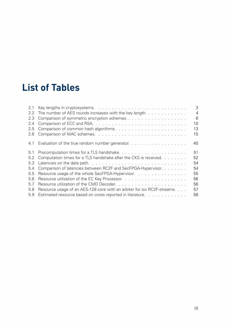
List of Tables
2.1 Key lengths in cryptosystems. . . . . . . . . . . . . . . . . . . . . . . . . . . . 32.2 The number of AES rounds increases with the key length. . . . . . . . . . . . . 42.3 Comparison of symmetric encryption schemes. . . . . . . . . . . . . . . . . . . 62.4 Comparison of ECC and RSA. . . . . . . . . . . . . . . . . . . . . . . . . . . . . 102.5 Comparison of common hash algorithms. . . . . . . . . . . . . . . . . . . . . . 132.6 Comparison of MAC schemes. . . . . . . . . . . . . . . . . . . . . . . . . . . . 15
4.1 Evaluation of the true random number generator. . . . . . . . . . . . . . . . . . 40
5.1 Precomputation times for a TLS handshake. . . . . . . . . . . . . . . . . . . . . 515.2 Computation times for a TLS handshake after the CKS is received. . . . . . . . 525.3 Latencies on the data path. . . . . . . . . . . . . . . . . . . . . . . . . . . . . . 545.4 Comparison of latencies between RC2F and SecFPGA-Hypervisor. . . . . . . . 545.5 Resource usage of the whole SecFPGA-Hypervisor. . . . . . . . . . . . . . . . 555.6 Resource utilization of the EC Key Processor. . . . . . . . . . . . . . . . . . . . 565.7 Resource utilization of the CMD Decoder. . . . . . . . . . . . . . . . . . . . . . 565.8 Resource usage of an AES-128 core with an arbiter for six RC2F-streams. . . . 575.9 Estimated resource based on cores reported in literature. . . . . . . . . . . . . 58
IX

List of AcronymsAE authenticated encryption
AES Advanced Encryption Standard
ASIC application-specific integrated cir-cuit
BRAM Block RAM
BSI Bundesamt für Sicherheit in der In-formationstechnik
CA certificate authority
CKS client key share
CPU central processing unit
CR client random
DSP digital signal processor
ECC elliptic curve cryptography
ECDH Elliptic Curve Diffie-Hellman
ECDHE Ephemeral Elliptic CurveDiffie-Hellman
ECDLP elliptic curve discrete logarithmproblem
ECDSA Elliptic Curve Digital Signature Al-gorithm
ECM elliptic curve multiplier
FIFO first in first out buffer
FPGA Field Programmable Gate Array
GCM Galois/Counter Mode
HLS High Level Synthesis
HMAC keyed-hash message authentica-tion code
IaaS Infrastructure as a Service
IP intellectual property
IV initialization vector
LUT look up table
MAC message authentication code
NIST National Institute of Standardsand Technology
nonce number used once
PaaS Platform as a Service
PCIe Peripheral Component Intercon-nect Express
PRE partial reconfiguration engine
PRNG pseudo random number genera-tor
PUF physically unclonable function
RC2F Reconfigurable Common Comput-ing Framework
ROM read only memory
RSA Rivest-Shamir-Adleman
S-Box substition box
SecFPGA Secured FPGA
SKS session key share
SPK session private key
X

LIST OF TABLES
SR session random
SSL Secure Sockets Layer
TA trusted authority
TLS Transport Layer Security
TPM Trusted Platform Module
TRNG true random number generator
vFPGA virtual FPGA
VM virtual machine
VMM virtual machine manager
XI

1 IntroductionThe flexibility of reconfigurable resources like FPGAs enables a unique combination of highthroughput and computing power with low energy consumption and time to market. Theypresent an excellent opportunity for data center providers to further increase their processingcapabilities without going beyond the boundaries of their power budget. The services providedby the data center are often called the cloud and are used by a wide range of different clients.However, sensitive data is not secure in those remote systems. The multilayered cloud environ-ment involves various different parties able to access the clients’ data. Potential security flawsin the complex software infrastructure enable even more attacks. Thus, a system is needed toestablish a trustworthy and secured space in a remote data center without sacrificing flexibility,energy efficiency and processing power.
Virtualizing the hardware into a flexible resource is essential to fulfill cloud characteristics andis still a topic of research. Other proposals explored security aspects and configuration updatesof remote FPGAs. Some require a secured setup by the client in a trusted environment, othersrely on a third party to establish trust in the remote system. However, most researchers focusonly on one specific area. Virtual FPGAs are not secure against malicious configurations, clients’intellectual property can be effortlessly extracted by the cloud provider and an adversary is ableto easily steal sensitive data. Approaches on security employ either setup strategies infeasiblein a cloud environment or only delegate the responsibility from one party to another, but anadditional third party does not reduce the required trust. Furthermore, virtualization is often notconsidered or only very limited, yet it is an essential part towards a flexible, highly optimizedand efficient cloud system.
This gap in current research is investigated in this thesis. A system should be designedand evaluated to unite energy efficiency and processing power with cloud characteristics likeflexibility and fast provisioning. Based on an FPGA design it can exploit their reconfigurability toprovide each client with an individual virtual FPGA. With security as the highest priority it mustenable a confidential transfer and processing of clients’ algorithms and data. Every connectionmust be trustworthy and protected against different levels of attackers. Even the cloud providershould not be able to access sensitive data. Thus, vulnerable software has to be avoided tooffer this high level of security.
This thesis is structured in the following way. After this introduction, important cryptographicalgorithms are outlined and a literature review investigates previous work in the field of cloudcomputing and virtualization of reconfigurable resources from the perspective of security. InChapter 3 a design is discussed to unite the virtualization and security requirements developedearlier. It is followed by the description of a prototypic implementation to verify crucial aspectsof the design. This prototype is evaluated in chapter 5 to analyze provided security and theoverhead it generates. In chapter 6 this thesis is summarized and future work outlined.
1

2 Background and Related Work
This chapter explores previous work in the field of cryptography, security, cloud computing, re-configurable resources and their virtualization. Each domain contributes with valuable insights,strong algorithms and elaborate concepts to the design of a secure hardware accelerator forthe cloud. In section 2.1 the focus is on established security schemes and protocols mixed withstate-of-the-art implementations whereas section 2.2 investigates more abstract constructs re-garding FPGAs, cloud and virtualization.
2.1 Background
One of the main goals of cryptography is to establish a trustworthy and confidential communi-cation between two parties over an insecure channel. Various fundamentally different schemesexist to solve the unique problems. However, none of them is unbreakable, in the worst casean attackers tries each possible combination, the so called brute-force attack. The security ofan algorithm is therefore determined by the number of operations an attacker has to executein order to break the secrecy. This number is primarily based on the length of the key used asthe starting secret, the underlying mathematical principle and the best known attack algorithm.Hence, different schemes require different key lengths to provide the same level of security,which is compared in Table 2.1.
Table 2.1: Comparison of key lengths in bit of different cryptographic systems. [Bro10, p. 15]
Security Level[operations]
AES(s. 2.1.1.1)
RSA(s. 2.1.2.1)
ECC(s. 2.1.2.2)
280 80 1024 1632128 128 3456 2832192 192 7680 4092256 256 15 360 571
This section outlines symmetric cryptography for fast de- and encryption first followed byasymmetric schemes to create common secrets. Section 2.1.3 describes how these schemescan be used to sign messages. Hash functions and message authentication codes are outlinedin section 2.1.4 and 2.1.5, respectively. Digital certificates and their chain of trust are essentialin a fast verification process and explained in section 2.1.6. Finally, the presented schemes andalgorithms are combined within the Transport Layer Security (TLS) protocol, which is describedin section 2.1.7.
3
2 Background and Related Work
2.1.1 Symmetric Cryptography
The first attempts to symmetrical cryptography were straightforward. Simple rotation ciphersshifted each letter by an offset. Shifting A to C requires a key-value of two, for an A to become anE the key has to be four. Both parties have to use the same key, which is used for decryptionand encryption, hence the name. But the substitution cipher can be broken easily by hand,analyzing the frequency distribution [Sin68] or other methods [PR79; UY06].
Nowadays far more complex but also far more secure algorithms exist, a few of them areoutlined in this section. First, section 2.1.1.1 describes Rijndael, also known as AES. After-wards, other symmetrical cryptographic algorithms are summarized in section 2.1.1.2. Finally,the schemes are compared in section 2.1.1.3.
2.1.1.1 Advanced Encryption Standard
In 1997 the US National Institute of Standards and Technology (NIST) launched a competitionfor a new symmetric block cipher [AES] to replace the slow and aging Data Encryption Standard(DES) [FIPS 46-2]. The winner was an algorithm called Rijndael, a combination of the last namesof its authors Daemen and Rijmen, but it is commonly referred to as Advanced EncryptionStandard (AES). They described a symmetric cipher with different key sizes, which is fast onhardware and software and free of patents [DR99]. This section first outlines the algorithm andafter that its security and possible attacks.
Rationale
AES is a 128-bit block cipher, in other words 128-bit can be encrypted with each run. A singlerun has multiple rounds, depending on the size of the key as shown in Table 2.2.
Table 2.2: The number of AES rounds increases with the key length.
key length rounds
128-bit 10192-bit 12256-bit 14
Before the first run the input is transformed into a 4x4 matrix of 8-bit words:
a0 b0 c0 d0
a1 b1 c1 d1
a2 b2 c2 d2
a3 b3 c3 d3
Each run consists of different steps working on this matrix: SubBytes, ShiftRow, MixColumn,AddRoundKey. SubBytes executes a nonlinear substitution to prevent the ciphertext yieldingany clues about the plaintext. This is done using a substition box (S-Box), each 8-bit word isreplaced with another 8-bit word. The substitution values were carefully chosen to be resilientagainst differential and linear cryptanalysis. This confusion is one of two principles in cipherdesign described by Shannon [Sha45]. The next step, ShiftRow, rotates each row to the left,the first one zero times, the second one once, the third twice and the fourth three times:
a0 b0 c0 d0
a1 b1 c1 d1
a2 b2 c2 d2
a3 b3 c3 d3
⇒
a0 b0 c0 d0
b1 c1 d1 a1
c2 d2 a2 b2
d3 a3 b3 c3
4
2.1 Background
This linear permutation shuffles the data around to change on average half of the output bits ifa single input bit changes. This is called diffusion and the next step, MixColumn, has the samegoal but is more complex and will not be explained further. AddRoundKey is the last step andapplies the key with a bitwise xor operation. To decrypt a ciphertext, the four steps have be toinverted and applied backwards. For a more in-depth coverage of the algorithm the book Thedesign of Rijndael: AES-the advanced encryption standard [DR13] is recommended.
Security and Attacks
To brute force a k-bit key it takes 2k operations. The full AES algorithm executes multiple roundsas shown in Table 2.2. Biryukov et al. have targeted AES-256 with only nine rounds and couldretrieve the key kA after 2131 operations [BKN09]. They used a related key kB, which is derivedfrom the original key kA with a special algorithm, to make this attack possible. The group aroundBiryukov optimized this related key approach further to break a nine round AES-256 in only 239
operations [Bir10]. However, since in practice only the full number of rounds and no related keyswould be used, these attacks are only theoretical. In 2011 Bogdanov et al. described the firstkey-recovery attack on full AES reducing the required time for a 128-bit key to 2126.2 [BKR11].But this attack is only slightly more practical since is only reduced the complexity by 2 bits andrequires 288 bits of data.
A class of threats with importance in practice are side channel attacks. They target hard-ware or software implementations, which are inadvertently leaking data. In 2006 Osvik et al.extracted a key after 800 operations or 65 ms through a cache-timing attack [OST06]. It wasrequired to run their software on the machine performing AES. A more efficient implementa-tion of a cache based attack was proposed by Ashokkumar et al. [AGM16]. Only a few AESoperations sufficed to calculate the secret key.
Even though theoretical and practical attacks are known, AES is recommended by variousauthorities [BSI17; NIST15] and is used in the latest TLS protocol [RFC 5246]. With a robustimplementation AES is considered to be secure.
2.1.1.2 Other Symmetric Encryption Algorithms
Another AES competition participant was the Blowfish successor called Twofish [Sch98]. Likethe other candidates is it a 128-bit block cipher and supports key lengths of 128, 192 and 256bits. It uses 16 rounds, generates S-Boxes from the key and uses whitening. Twofish utilizesmore conservative components than the AES winner Rijndael. Lucks published an attack, which,however, targets only six to eight rounds and is therefore only theoretical [Luc02]. No practicalattacks are known and Twofish is considered to be secure [Sch13, p. 145].
KASUMI is based on MISTY1 and was developed in 1999 to be used in the Universal MobileTelecommunications System standard, hence it is one of the most used symmetrical encryptionschemes [KASUMI01]. The algorithm was designed especially for hardware implementationsand is based on a Feistel cipher with eight rounds. The key length is 128-bit and it has to beexpanded eight times so each round uses a different sub key. This key extension was identifiedas a weak spot by Dunkelman et al. [DKS10]. Using related keys, they showed that KASMUIcan be broken with a time complexity of only 232. Therefore, they recommend to avoid thealgorithm if a related-key attack can be mounted.
Salsa20 was developed by Bernstein and supports keys of 128 and 256 bit length [Ber08b].It is a stream cipher with a different design approach compared to others like RC4 or A5. Moststream ciphers use a complex function to generate pseudo randomness from the symmetrickey and simple extract methods to create the keystream, which will be XORed with the plaintext to output the cipher text. Salsa20, on the other hand, uses the key as the start value fora simple counter. The far more sophisticated extraction method generates a cryptographically
5

2 Background and Related Work
secure keystream. At time of writing, only attacks targeting eight of the twelve or twentyrounds are published [Aum08]. That the slightly changed ChaCha20 algorithm [Ber08a] wasadded as a cipher suite for the TLS protocol in 2016 [RFC 7905] shows the confidence thecommunity places in its security.
2.1.1.3 Comparison of Symmetric Cryptographic Systems
In Table 2.3 different symmetrical encryption schemes are compared. Both AES candidatessupport 128, 192 and 256-bit keys, Salsa20 and ChaCha20 128 and 256-bit keys and KASUMIonly a fixed length of 128 bits. Furthermore, KASUMI is vulnerable to a related-key attack withpractical complexity. No feasible practical attacks are public known for the two AES candidatesas well as Salsa20/ChaCha20. One reason why Rijndeal was selected in favor of Twofish is itsbetter efficiency, both in hardware and software. Today, many central processing units (CPUs)and systems on a chip support dedicated instructions, like Intel’s AES-NI [AES-NI], to acceleratethe AES winning algorithm. Since its selection, a wide variety of implementations have beenreported in literature. They range from high throughputs of 260 149 Mbit/ s [SS15] to a highefficiency of 42.27 Mbit/ s/ slice [SA11]. But to better compare AES and ChaCha20 Table 2.3lists numbers from a single paper. Sugier showed that the stream cipher is faster on FPGAs,but because it is not yet supported by hardware extensions of CPUs it offers less throughputon these platforms. KASUMI was designed for hardware implementations in low-end devicesand a decent throughput can be achieved.
Table 2.3: Comparison of symmetric encryption schemes.
Property AES (Rijndael) Twofish KASUMI ChaCha20
Key length in bit 128, 192, 256 128, 192, 256 128 128, 256Practical attacks none none related-key noneCPU cycles per byte 0.7a, b, c, d 16.6a, b, c 68.8a, e 6.0c, f
Throughput (FPGA)g 24 400a, h 177a, i 3 584a, k 33 700f, h
Speed/Area (FPGA)m 9.87a, h 0.164a, i 0.756a, k 6.36f, h
a 128-bit keyb CTR mode [DH79]c [CryptoPP]d [AES-NI] support
e [BK15]f 256-bit keyg in Mbit/ sh [Sug13], Xilinx Spartan 6
i [GC01], Xilinx XCV-1000k [KGK04], Xilinx XCV300Em in Mbit/ s/ slice
2.1.2 Asymmetric Cryptography
Also known as public key cryptography, these schemes are based on two distinct keys. One ofthem, the private key, has to be kept secret by the sender while the second one is available toanyone, including attackers and eavesdroppers. It is therefore called public key. In 1976 Diffieand Hellman proposed this concept [DH76]. They described how the public key can be derivedfrom a private key using simple operations, e.g. multiplication. However, computation of theprivate key based only on the public key has to be infeasible.
This section describes multiple mathematical operations, which fulfill this requirement, start-ing with integer factorization and the popular RSA scheme based on it. Elliptic curves are usedby various algorithms and outlined in section 2.1.2.2. Afterwards, the two concepts are com-pared and a key exchange scheme concludes the section.
2.1.2.1 RSA Cryptosystem
The concept from Diffie and Hellman lacked an implementation for a one-way function. This in-spired Rivest, Shamir and Adleman to investigate and a year later in 1978 they described such a
6

2.1 Background
function in their paper “A method for obtaining digital signatures and public-key cryptosystems”[RSA78]. The name is composed of the first letters of the researchers’ names: RSA.
Today RSA is used in the Secure Sockets Layer (SSL) standard [RFC 6101] and its succes-sors among others, protocols to ensure secure web hosting, instant messaging, email andmore. It can be used to encrypt messages as well as authentication. However, because RSAis comparatively slow, it is often only used to encrypt and transmit a key for faster symmetricalgorithms. This section first describes the underlying maths while the security and knownattacks are evaluated afterwards.
Rationale
RSA is based on the computational complexity of factoring an integer product. No algorithm ofpolynomial complexity are publicly known and it appears to be a hard problem. In the first steptwo large prime numbers a and b are chosen at random and must be kept secret. Their productn will be used as a modulus and is one part of the public key tuple as well as the private keytuple. Next, the totient t has to be calculated. It is defined by Equation 2.1 where lcm is theleast common multiple.
t = λ(n) = lcm(a − 1, b − 1) (2.1)
The second part of the public key tuple PK is e with 1 < e < t and e coprime to t.
public key PK = (e, n) (2.2)
The private key tuple pk is completed by d, the modular multiplicative inverse to e under t:
d ≡ e−1 mod t (2.3)
private key pk = (d, n) (2.4)
Anyone can encrypt a plaintext message x with the public key tuple PK and function c definedin Equation 2.5 to get the encrypted message x|PK .
x|PK = c(x) ≡ xe mod n (2.5)
Decrypting the ciphertext x|PK is only possible with the private key tuple pk = (d, n) usingfunction m defined in Equation 2.6.
x = m(x|PK ) ≡ x|PKd mod n (2.6)
But not only encryption is possible, the possession of a private key component d can alsobe verified. To prove it the sender sings a plaintext message xs with the decryption functionm. The message xs and the signed one xs|pk are transmitted. Any recipient can now verify thatthe sender is in possession of the private key component d by applying the encryption functionc to the signed message xs|pk with the available public key tuple PK and comparing it to theplaintext xs.
Security and Attacks
The security level of RSA is primarily based on the size of the prime numbers a and b and theresulting product n. The number of bits of n determines the key length. Factoring attacks tryto find the prime numbers used to calculate n. The fastest known method, the General NFSalgorithm [Len93], has a sub-exponential runtime and was used to factor a 768-bit RSA key in2009 [Kle10]. This 768-bit number was one of the RSA numbers published by RSA Security intheir RSA Factoring Challenge [RSAC91]. At the time of writing no larger numbers are factored.
7

2 Background and Related Work
However, even 1024-bit keys are not considered secure. Therefore the German Bundesamt fürSicherheit in der Informationstechnik (BSI) and the US NIST recommend key lengths of at least2000 bit [BSI17; NIST15] to prevent factoring.
But there are other attacks targeting the mathematical system, weaknesses in parameterand prime selection or the hardware implementation itself. Dubey et al. surveys those attacksand lists countermeasures [Dub14]. They conclude that none of the attacks are a serious threatif the algorithm is implemented correctly. Therefore, RSA is considered to be secure. Onlyquantum computers appear able to break the scheme. Shor developed a polynomial time quan-tum algorithm rendering RSA obsolete if those computers reach the required processing power[Sho99].
2.1.2.2 Elliptic Curve Cryptography
Elliptic curve cryptography (ECC) was first independently proposed by Miller [Mil85] and Koblitz[Kob87] in 1985. It was widely adapted in 2005 after the OpenSSL team accepted a relevantpatch and the U.S. National Security Agency announced Suite B [Nat15], a set of cryptographicalgorithms containing a digital signature and a key agreement scheme based on ECC. Oneof the main factors limiting a wider use is the unclear patent situation. BlackBerry holds manypatents relating ECC, but some claim that alternative not patented techniques still allow efficientimplementations [Ful07].
This section first outlines the concepts ECC is based on. For more detailed insights theoriginal papers [Kob87; Mil85] are recommended. The second part focuses on the securityaspects and possible attacks.
Rationale
An elliptic curve is defined by equation 2.7 over a finite field and a point O in infinity.
y2 = x3 + ax + b (2.7)
It can be shown that a line intersecting with the curve always has exactly three points of inter-section.
1. For a line parallel to the y -axis the third point is O.2. If the line is tangent to the curve, the point of intersection counts twice.3. With all other lines the points of intersection are obvious.
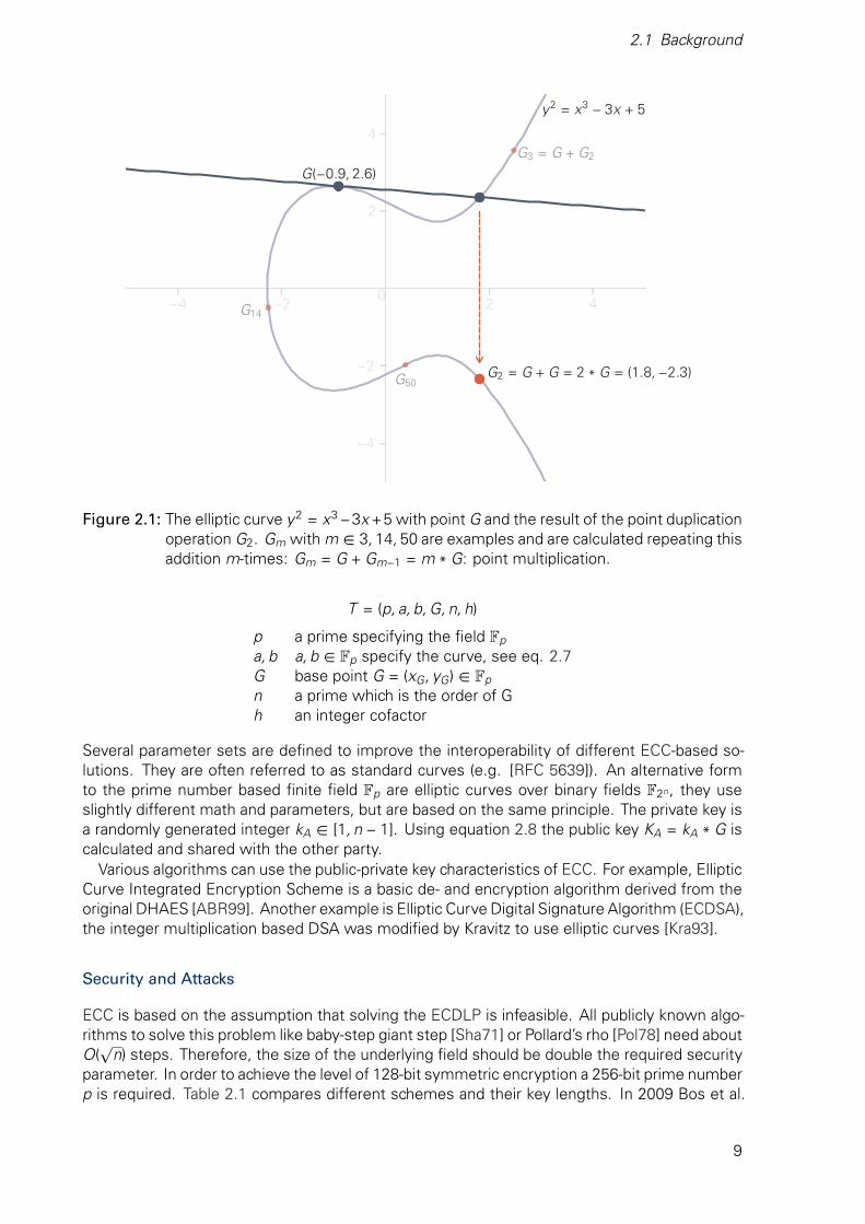
Using this property it is possible to define an addition operation. A special case, point doublingi. e. adding point G to itself, is illustrated in Figure 2.1. Because it is only a single point, case2 is in effect and a line tangent to the curve is used. The resulting point of intersection ismirrored on the x-axis to yield the final sum G2. Repeating this operation m-times is calledpoint multiplication and is defined through equation 2.8.
Q = m * G (2.8)
There are efficient algorithms to calculate Q from m and G, for example the Montgomery lad-der [Mon87]. The inverse operation, calculating m with given Q and G, is the elliptic curvediscrete logarithm problem (ECDLP) and no efficient classical algorithms are publicly known.Therefore, ECC is based on the assumption that the ECDLP is in fact a hard problem and aclassical algorithm with polynomial complexity cannot exist.
To use this asymmetric encryption scheme two parties have to agree on a parameter setwhich is defined by the sextuple T :
8
2.1 Background
−4 −2 2 4
−4
−2
2
4G3 = G + G2
G14
G50
0
y2 = x3 − 3x + 5
G(−0.9, 2.6)
G2 = G + G = 2 * G = (1.8, −2.3)
Figure 2.1: The elliptic curve y2 = x3 −3x +5 with point G and the result of the point duplicationoperation G2. Gm with m ∈ 3, 14, 50 are examples and are calculated repeating thisaddition m-times: Gm = G + Gm−1 = m * G: point multiplication.
T = (p, a, b, G, n, h)
p a prime specifying the field Fp
a, b a, b ∈ Fp specify the curve, see eq. 2.7G base point G = (xG, yG) ∈ Fp
n a prime which is the order of Gh an integer cofactor
Several parameter sets are defined to improve the interoperability of different ECC-based so-lutions. They are often referred to as standard curves (e.g. [RFC 5639]). An alternative formto the prime number based finite field Fp are elliptic curves over binary fields F2n , they useslightly different math and parameters, but are based on the same principle. The private key isa randomly generated integer kA ∈ [1, n − 1]. Using equation 2.8 the public key KA = kA * G iscalculated and shared with the other party.
Various algorithms can use the public-private key characteristics of ECC. For example, EllipticCurve Integrated Encryption Scheme is a basic de- and encryption algorithm derived from theoriginal DHAES [ABR99]. Another example is Elliptic Curve Digital Signature Algorithm (ECDSA),the integer multiplication based DSA was modified by Kravitz to use elliptic curves [Kra93].
Security and Attacks
ECC is based on the assumption that solving the ECDLP is infeasible. All publicly known algo-rithms to solve this problem like baby-step giant step [Sha71] or Pollard’s rho [Pol78] need aboutO(
√n) steps. Therefore, the size of the underlying field should be double the required security
parameter. In order to achieve the level of 128-bit symmetric encryption a 256-bit prime numberp is required. Table 2.1 compares different schemes and their key lengths. In 2009 Bos et al.
9
2 Background and Related Work
computed a discrete logarithm on an elliptic curve with a 112-bit prime in about six monthsusing 200 PlayStation 3 [Bos12]. Almost six years later, in January 2015, the computation in a113-bit binary field was successful. Wenger and Wolfger used a 10-core Kintex-7 FPGA clusterfor 82 days [WW16]. To break 256-bit ECC in one year of computation they estimate basedon their implementation that hardware worth 18.1 · 1024 US$ is needed, hence 256-bit can beconsidered sufficiently secure for the next decade.
However, a novel ground braking algorithm or advances in quantum computers could breakECC. Proos and Zalka [PZ03] and Kaye [Kay05] describe quantum algorithms to calculate thediscrete logarithm in polynomial time over prime and binary fields, respectively. But quantumcomputers are not needed to exploit weaknesses in the implementation. Several physical at-tacks are known and have to be considered during the design. Passive attacks, also called sidechannel analysis, and active or fault attacks require access to the device but have shown to beeffective [De 05; KSZ11; FGV11]. Fan and Verbauwhede surveyed them and showed possiblecounter measurements to limit the effectiveness of such attacks [FV12].
2.1.2.3 Comparison of Asymmetric Cryptographic Systems
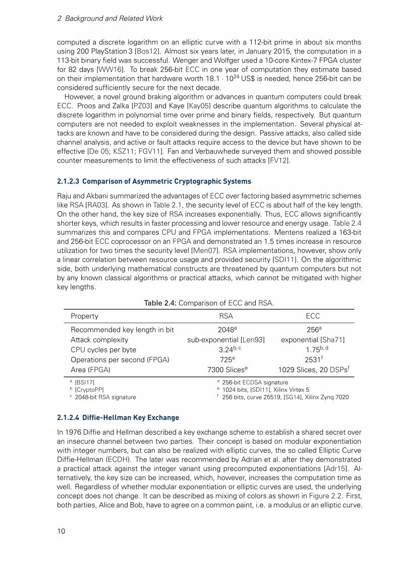
Raju and Akbani summarized the advantages of ECC over factoring based asymmetric schemeslike RSA [RA03]. As shown in Table 2.1, the security level of ECC is about half of the key length.On the other hand, the key size of RSA increases exponentially. Thus, ECC allows significantlyshorter keys, which results in faster processing and lower resource and energy usage. Table 2.4summarizes this and compares CPU and FPGA implementations. Mentens realized a 163-bitand 256-bit ECC coprocessor on an FPGA and demonstrated an 1.5 times increase in resourceutilization for two times the security level [Men07]. RSA implementations, however, show onlya linear correlation between resource usage and provided security [SDI11]. On the algorithmicside, both underlying mathematical constructs are threatened by quantum computers but notby any known classical algorithms or practical attacks, which cannot be mitigated with higherkey lengths.
Table 2.4: Comparison of ECC and RSA.
Property RSA ECC
Recommended key length in bit 2048a 256a
Attack complexity sub-exponential [Len93] exponential [Sha71]CPU cycles per byte 3.24b, c 1.75b, d
Operations per second (FPGA) 725e 2531f
Area (FPGA) 7300 Slicese 1029 Slices, 20 DSPsf
a [BSI17]b [CryptoPP]c 2048-bit RSA signature
d 256-bit ECDSA signaturee 1024 bits, [SDI11], Xilinx Virtex 5f 256 bits, curve 25519, [SG14], Xilinx Zynq 7020
2.1.2.4 Diffie-Hellman Key Exchange
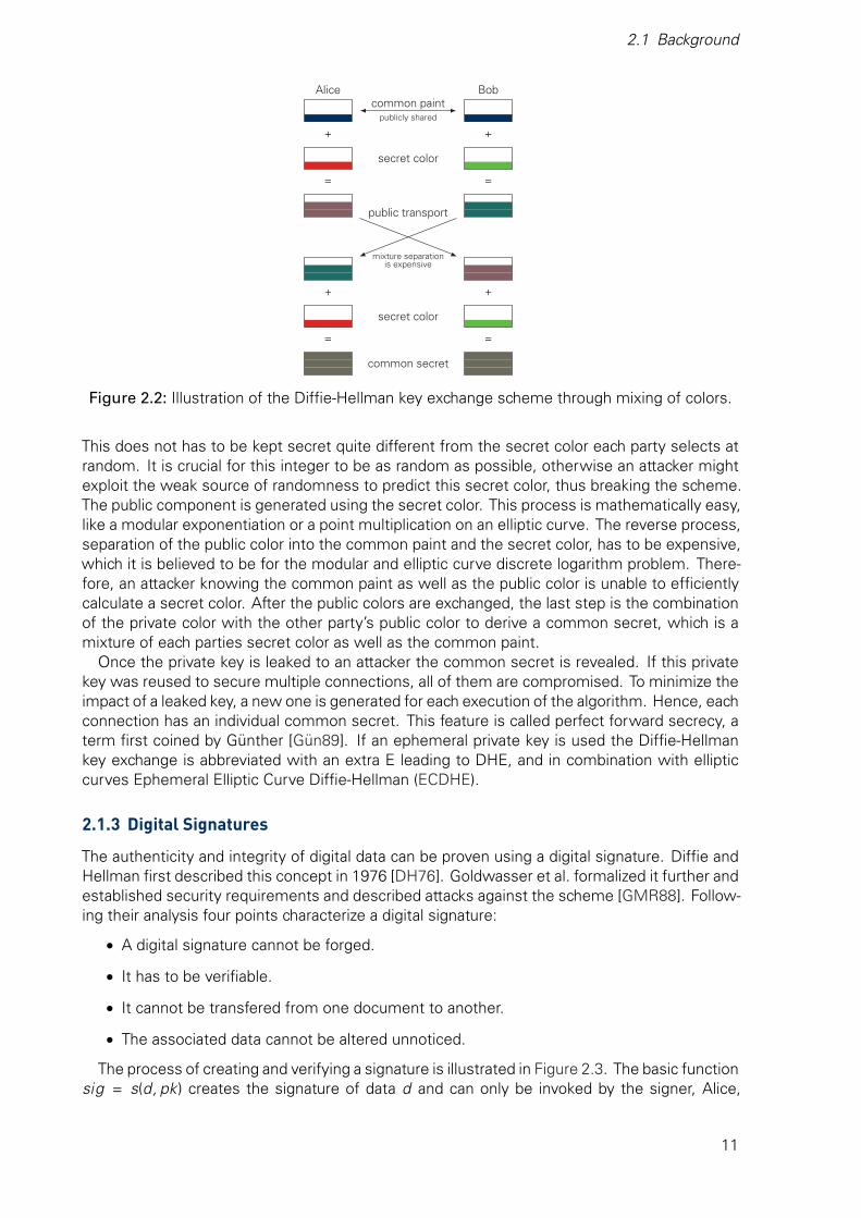
In 1976 Diffie and Hellman described a key exchange scheme to establish a shared secret overan insecure channel between two parties. Their concept is based on modular exponentiationwith integer numbers, but can also be realized with elliptic curves, the so called Elliptic CurveDiffie-Hellman (ECDH). The later was recommended by Adrian et al. after they demonstrateda practical attack against the integer variant using precomputed exponentiations [Adr15]. Al-ternatively, the key size can be increased, which, however, increases the computation time aswell. Regardless of whether modular exponentiation or elliptic curves are used, the underlyingconcept does not change. It can be described as mixing of colors as shown in Figure 2.2. First,both parties, Alice and Bob, have to agree on a common paint, i.e. a modulus or an elliptic curve.
10
2.1 Background
Alice Bob
+
=
+
=
+
=
+
=
secret color
secret color
common secret
common paintpublicly shared
public transport
mixture separationis expensive
Figure 2.2: Illustration of the Diffie-Hellman key exchange scheme through mixing of colors.
This does not has to be kept secret quite different from the secret color each party selects atrandom. It is crucial for this integer to be as random as possible, otherwise an attacker mightexploit the weak source of randomness to predict this secret color, thus breaking the scheme.The public component is generated using the secret color. This process is mathematically easy,like a modular exponentiation or a point multiplication on an elliptic curve. The reverse process,separation of the public color into the common paint and the secret color, has to be expensive,which it is believed to be for the modular and elliptic curve discrete logarithm problem. There-fore, an attacker knowing the common paint as well as the public color is unable to efficientlycalculate a secret color. After the public colors are exchanged, the last step is the combinationof the private color with the other party’s public color to derive a common secret, which is amixture of each parties secret color as well as the common paint.
Once the private key is leaked to an attacker the common secret is revealed. If this privatekey was reused to secure multiple connections, all of them are compromised. To minimize theimpact of a leaked key, a new one is generated for each execution of the algorithm. Hence, eachconnection has an individual common secret. This feature is called perfect forward secrecy, aterm first coined by Günther [Gün89]. If an ephemeral private key is used the Diffie-Hellmankey exchange is abbreviated with an extra E leading to DHE, and in combination with ellipticcurves Ephemeral Elliptic Curve Diffie-Hellman (ECDHE).
2.1.3 Digital Signatures
The authenticity and integrity of digital data can be proven using a digital signature. Diffie andHellman first described this concept in 1976 [DH76]. Goldwasser et al. formalized it further andestablished security requirements and described attacks against the scheme [GMR88]. Follow-ing their analysis four points characterize a digital signature:
• A digital signature cannot be forged.
• It has to be verifiable.
• It cannot be transfered from one document to another.
• The associated data cannot be altered unnoticed.
The process of creating and verifying a signature is illustrated in Figure 2.3. The basic functionsig = s(d, pk) creates the signature of data d and can only be invoked by the signer, Alice,
11

2 Background and Related Work
because only she knowns her private key pk. The associated public key PK is distributedand available to anybody. The receiver Bob uses it and the signature sig and to verify d withd ′ = v (sig, PK ). If d and d ′ match, Alice did in fact send d to Bob.
This issome data.
5c6be9f32a4 ? yes? no
plain datad
private keypk
signaturesig = s(d, pk)
public keyPK
verificationd ?= v (sig, PK )
Figure 2.3: Basic concept of a digital signature (adapted from [Sch13, p. 202]). The signatureis created with the private key and verified with the public key.
The asymmetric encryption algorithm RSA, described in section 2.1.2.1, can also be used tocreate digital signatures. Alice “encrypts” the plain data d with her private key tuple pk. Bobcan verify it by “decrypting” it with the public key tuple PK . Another algorithm is the Digital Sig-nature Algorithm (DSA), it was patented in 1991 by Kravitz but was made available royalty-freeworldwide [Kra93]. Today, the scheme uses a longer SHA-2 hash algorithm and modular arith-metic with prime numbers. A variation called Elliptic Curve Digital Signature Algorithm (ECDSA)uses elliptic curves, hence it is faster and requires smaller keys as shown in Table 2.4.
2.1.4 Hash Functions
Using digital signatures explained in section 2.1.3 to sign a whole message is slow and thesignature is about as long as the message itself. In practice a hash function is applied to themessage to generate a short sequence which can be signed much quicker. The goal of a hashfunction is therefore to map an arbitrary large input to an output with a fixed size, e.g. 160 bitfor SHA-1. To be useful in cryptography a hash function has to have several properties [RS04]:
• The same input results always in the same output.
• A single bit modification of the input changes half of the output - avalanche effect [WT86].
• The mapping must be as unique as possible and evenly distributed.
• It is infeasible to generate a collision, i.e. find a second input with the same hash.
• It is infeasible to reconstruct the message from the hash.
To achieve such a behavior, techniques similar to symmetric encryption are used. Binary op-erations applied to chunks of the data in multiple rounds aim to confuse and diffuse [Sha45].However, this one-way function does not require a key, hence it does not encrypt the message.
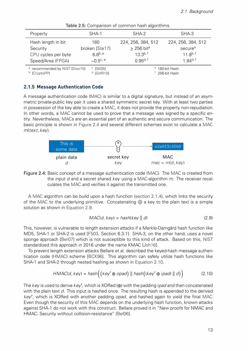
A multitude of hash functions were developed over time. Table 2.5 compares members ofthe popular SHA family. SHA-1 was specified in 1995 [FIPS 180-1]. Its successor SHA-2 wasalso commissioned by the USA and standardized in [FIPS 180-2]. SHA-3, on the other hand,was the winner of a competition organized by NIST and proposed by Bertoni et al. in 2007[Ber07]. It does not replace SHA-2, but complements it. Although SHA-1 is the fastest of theSHA family it should not be used any longer. A collision was found in 2017 by Stevens et al.[Ste17]. No collisions are publicly disclosed for the other algorithms and they continue to berecommended [Dwo15]. Of those two the SHA-3 functions performs more faster on CPUs andmore efficiently on FPGAs.
12
2.1 Background
Table 2.5: Comparison of common hash algorithms.
Property SHA-1 SHA-2 SHA-3
Hash length in bit 160 224, 256, 384, 512 224, 256, 384, 512Security broken [Ste17] >− 256 bita securea
CPU cycles per byte 6.8b, e 13.3b, f 11.8b, f
Speed/Area (FPGA) ~0.5c, e 0.95d, f 1.84d, f
a recommended by NIST [Dwo15]b [CryptoPP]
c [SK05]d [GHR10]
e 160-bit Hashf 256-bit Hash
2.1.5 Message Authentication Code
A message authentication code (MAC) is similar to a digital signature, but instead of an asym-metric private-public key pair it uses a shared symmetric secret key. With at least two partiesin possession of the key able to create a MAC, it does not provide the property non-repudiation.In other words, a MAC cannot be used to prove that a message was signed by a specific en-tity. Nevertheless, MACs are an essential part of an authentic and secure communication. Thebasic principle is shown in Figure 2.4 and several different schemes exist to calculate a MACm(text, key ).
This issome data.
e2a6f3c45b9
plain datad
secret keykey
MACmac = m(d, key )
Figure 2.4: Basic concept of a message authentication code (MAC). The MAC is created fromthe input d and a secret shared key using a MAC-algorithm m. The receiver recal-culates the MAC and verifies it against the transmitted one.
A MAC algorithm can be build upon a hash function (section 2.1.4), which links the securityof the MAC to the underlying primitive. Concatenating (||) a key to the plain text is a simplesolution as shown in Equation 2.9.
MAC(d, key ) = hash(key || d) (2.9)
This, however, is vulnerable to length extension attacks if a Merkle-Damgård hash function likeMD5, SHA-1 or SHA-2 is used [FS03, Section 6.3.1]. SHA-3, on the other hand, uses a novelsponge approach [Ber07] which is not susceptible to this kind of attack. Based on this, NISTstandardized this approach in 2016 under the name KMAC [Joh16].
To prevent length extension attacks Bellare et al. described the keyed-hash message authen-tication code (HMAC) scheme [BCK96]. This algorithm can safely utilize hash functions likeSHA-1 and SHA-2 through nested hashing as shown in Equation 2.10.
HMAC(d, key ) = hash((
key ′ ⊕ opad)
|| hash((key ′ ⊕ ipad) || d
))(2.10)
The key is used to derive key ′, which is XORed (⊕) with the padding ipad and then concatenatedwith the plain text d. This input is hashed once. The resulting hash is appended to the derivedkey ′, which is XORed with another padding opad, and hashed again to yield the final MAC.Even though the security of this MAC depends on the underlying hash function, known attacksagainst SHA-1 do not work with this construct. Bellare proved it in “New proofs for NMAC andHMAC: Security without collision-resistance” [Bel06].
13
2 Background and Related Work
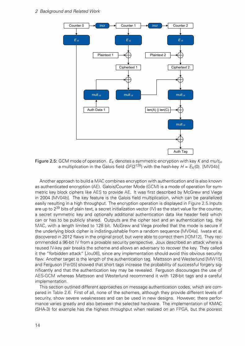
Figure 2.5: GCM mode of operation. EK denotes a symmetric encryption with key K and multH
a multiplication in the Galois field GF (2128) with the hash-key H = EK (0). [MV04b]
Another approach to build a MAC combines encryption with authentication and is also knownas authenticated encryption (AE). Galois/Counter Mode (GCM) is a mode of operation for sym-metric key block ciphers like AES to provide AE. It was first described by McGrew and Viegain 2004 [MV04b]. The key feature is the Galois field multiplication, which can be parallelizedeasily resulting in a high throughput. The encryption operation is displayed in Figure 2.5.Inputsare up to 239 bits of plain text, a secret initialization vector (IV) as the start value for the counter,a secret symmetric key and optionally additional authentication data like header field whichcan or has to be publicly shared. Outputs are the cipher text and an authentication tag, theMAC, with a length limited to 128 bit. McGrew and Viega proofed that the mode is secure ifthe underlying block cipher is indistinguishable from a random sequence [MV04a]. Iwata et al.discovered in 2012 flaws in the original proof, but were able to correct them [IOM12]. They rec-ommended a 96-bit IV from a provable security perspective. Joux described an attack where areused IV-key pair breaks the scheme and allows an adversary to recover the key. They calledit the “forbidden attack“ [Jou06], since any implementation should avoid this obvious securityflaw. Another target is the length of the authentication tag. Mattsson and Westerlund [MW15]and Ferguson [Fer05] showed that short tags increase the probability of successful forgery sig-nificantly and that the authentication key may be revealed. Ferguson discourages the use ofAES-GCM whereas Mattsson and Westerlund recommend it with 128-bit tags and a carefulimplementation.
This section outlined different approaches on message authentication codes, which are com-pared in Table 2.6. First of all, none of the schemes, although they provide different levels ofsecurity, show severe weaknesses and can be used in new designs. However, there perfor-mance varies greatly and also between the selected hardware. The implementation of KMAC(SHA-3) for example has the highest throughput when realized on an FPGA, but the poorest
14

2.1 Background
performance on a CPU, which is compared with the others in Figure 2.6. There, HMAC-SHA-1and GCM perform best with HMAC-SHA-256 only marginally faster than KMAC. It should benoted that the depicted speed includes an AES-128 encryption of the data, a benefit of the AEapproach.
Table 2.6: Comparison of message authentication code schemes.
Property HMAC-SHA-1 HMAC-SHA-256 KMAC-256 GCM
Tag length in bit 160 224-512 224-512 128Security level 160 224-512 224-512 128Usage HMAC HMAC KMAC AECPU cycles per byte see Figure 2.6Throughput (FPGA)a 1 587c, f 10 886e, g 37 632e, h 36 920d, i
Speed/Area (FPGA)b 0.265c, f 2.722e, g 9.141e, h 7.740d, i
a in Mbit/ sb in Mbit/ s/ slicec Xilinx Virtex E
d Xilinx Virtex 5e Xilinx Virtex 6f [Mic04]
g [Mic12]h [MIV15]i [ACM14]
102 103 104 105 106 107 108 109
Data Size in Byte
0
2500
5000
7500
10000
12500
CP
US
peed
inM
bit/
s
HMAC-SHA-1 HMAC-SHA-256 KMAC-256 (SHA-3) AES-GCM
0
2500
5000
7500
10000
12500
Figure 2.6: CPU performance comparison of different MAC schemes. Benchmark was per-formed on a Linux host with OpenSSL 1.1.1.
2.1.6 Certificates
Certificates build upon digital signatures described in section 2.1.3. They are a wrapper andinclude more information, e.g. who signed it. Standards like X.509 [ITU93] or Pretty GoodPrivacy (PGP) [RFC 4880] describe how such a certificate is structured and what informationhave to be included. A X.509 example for the website tu-dresden.de is shown in Figure 2.7.It includes, among others, a name, the public key of the server, a validity period, the publickey PKca of the entity signing it and a fingerprint. This fingerprint is a digital signature in formof a SHA-256 hash encrypted with the private key of the signing entity. The client uses theissuer’s public key PKca to “decrypt” it and compares the plain hash to a locally computed one.If they match, the certificate is authentic and was not modified. Yet the client has to trust inthe legitimacy of the signing entity. In case of tu-dresden.de it is TU Dresden CA - G02, theorganization controlling the server created a certificate for itself. However, another organization,namely DFN-Verein PCA Global - G01, issued a certificate to TU Dresden CA - G02 and allowed
15
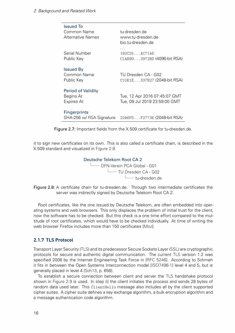
2 Background and Related Work
Issued ToCommon Name tu-dresden.deAlternative Names www.tu-dresden.de
bio.tu-dresden.de. . .
Serial Number 1B2C25...AC71AEPublic Key C1AB9D...3972BD (4096-bit RSA)
Issued ByCommon Name TU Dresden CA - G02Public Key C10E1E...337B27 (2048-bit RSA)
Period of ValidityBegins At Tue, 12 Apr 2016 07:45:07 GMTExpires At Tue, 09 Jul 2019 23:59:00 GMT
FingerprintsSHA-256 w/ RSA Signature 22A6FD...F2773E (2048-bit RSA)
Figure 2.7: Important fields from the X.509 certificate for tu-dresden.de.
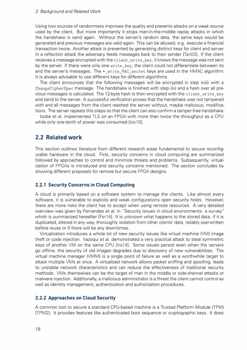
it to sign new certificates on its own. This is also called a certificate chain, is described in theX.509 standard and visualized in Figure 2.8.
Deutsche Telekom Root CA 2DFN-Verein PCA Global - G01
TU Dresden CA - G02tu-dresden.de
Figure 2.8: A certificate chain for tu-dresden.de. Through two intermediate certificates theserver was indirectly signed by Deutsche Telekom Root CA 2.
Root certificates, like the one issued by Deutsche Telekom, are often embedded into oper-ating systems and web browsers. This only displaces the problem of initial trust for the client,now the software has to be checked. But this check is a one time effort compared to the mul-titude of root certificates, which would have to be checked individually. At time of writing theweb browser Firefox includes more than 150 certificates [Moz].
2.1.7 TLS Protocol
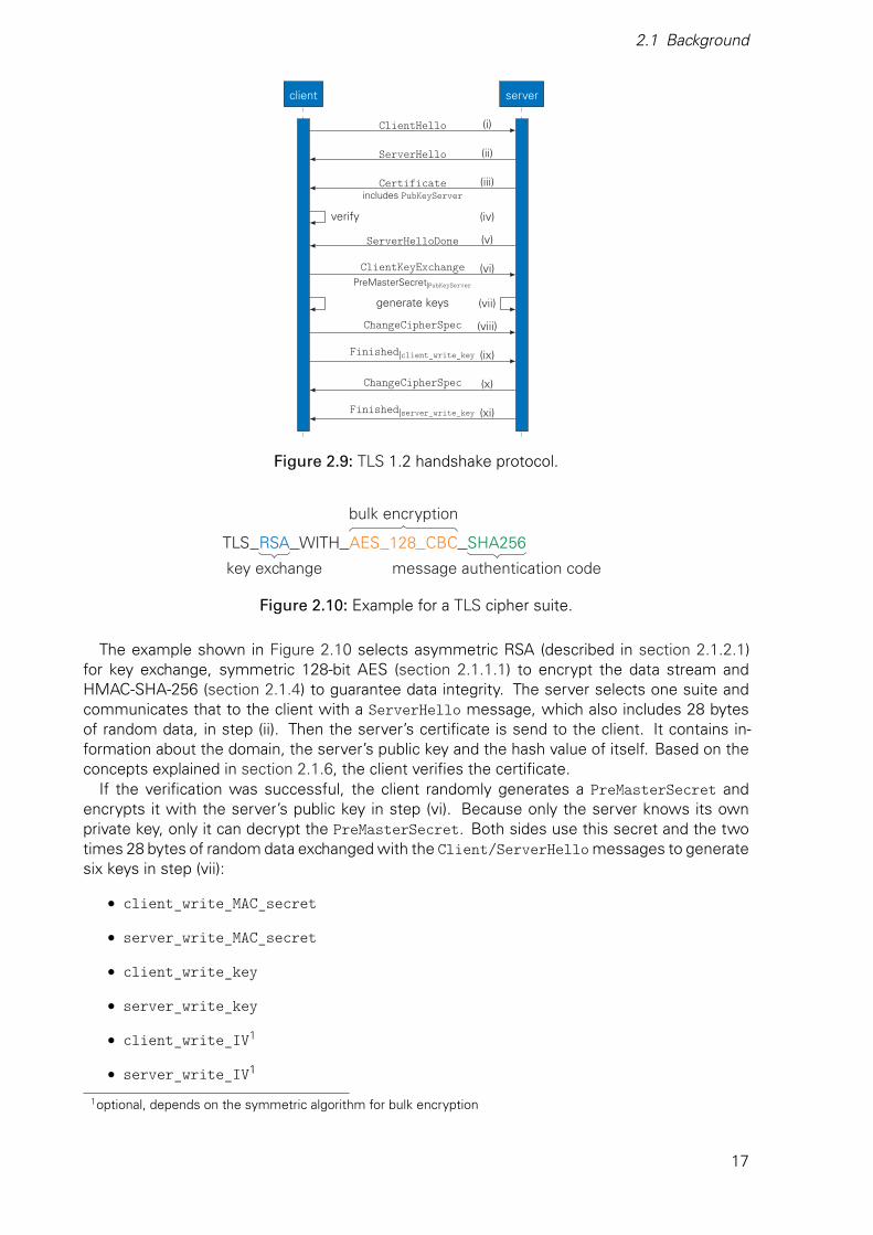
Transport Layer Security (TLS) and its predecessor Secure Sockets Layer (SSL) are cryptographicprotocols for secure and authentic digital communication. The current TLS version 1.2 wasspecified 2008 by the Internet Engineering Task Force in [RFC 5246]. According to Schmehit fits in between the Open Systems Interconnection model [ISO7498-1] level 4 and 5, but isgenerally placed in level 4 [Sch13, p. 656].
To establish a secure connection between client and server the TLS handshake protocolshown in Figure 2.9 is used. In step (i) the client initiates the process and sends 28 bytes ofrandom data used later. This ClientHello message also includes all by the client supportedcipher suites. A cipher suite defines a key exchange algorithm, a bulk encryption algorithm anda message authentication code algorithm.
16
2.1 Background
client server
ClientHello
ServerHello
Certificateincludes PubKeyServer
verify
ServerHelloDone
ClientKeyExchangePreMasterSecret|PubKeyServer
generate keys
ChangeCipherSpec
Finished|client_write_key
ChangeCipherSpec
Finished|server_write_key
(i)
(ii)
(iii)
(iv)
(v)
(vi)
(vii)
(viii)
(ix)
(x)
(xi)
Figure 2.9: TLS 1.2 handshake protocol.
TLS RSA WITH AES 128 CBC SHA256
key exchange
bulk encryption
message authentication code
Figure 2.10: Example for a TLS cipher suite.
The example shown in Figure 2.10 selects asymmetric RSA (described in section 2.1.2.1)for key exchange, symmetric 128-bit AES (section 2.1.1.1) to encrypt the data stream andHMAC-SHA-256 (section 2.1.4) to guarantee data integrity. The server selects one suite andcommunicates that to the client with a ServerHello message, which also includes 28 bytesof random data, in step (ii). Then the server’s certificate is send to the client. It contains in-formation about the domain, the server’s public key and the hash value of itself. Based on theconcepts explained in section 2.1.6, the client verifies the certificate.
If the verification was successful, the client randomly generates a PreMasterSecret andencrypts it with the server’s public key in step (vi). Because only the server knows its ownprivate key, only it can decrypt the PreMasterSecret. Both sides use this secret and the twotimes 28 bytes of random data exchanged with the Client/ServerHello messages to generatesix keys in step (vii):
• client_write_MAC_secret
• server_write_MAC_secret
• client_write_key
• server_write_key
• client_write_IV1
• server_write_IV1
1optional, depends on the symmetric algorithm for bulk encryption
17
2 Background and Related Work
Using two sources of randomness improves the quality and prevents attacks on a weak sourceused by the client. But more importantly it stops man-in-the-middle replay attacks in whichthe handshake is send again. Without the server’s random data, the same keys would begenerated and previous messages are valid again. This can be abused, e.g. execute a financialtransaction twice. Another attack is prevented by generating distinct keys for client and server.In a reflection attack the adversary feeds messages back to their sender [Tan03]. If the clientreceives a message encrypted with the client_write_key, it knows the message was not sentby the server. If there were only one write_key, the client could not differentiate between itsand the server’s messages. The *_write_MAC_secret keys are used in the HMAC algorithm.It is always advisable to use different keys for different algorithms.
The client announces that the following messages will be encrypted in step (viii) with aChangeCipherSpec message. The handshake is finished with step (ix) and a hash over all pre-vious messages is calculated. The 12-byte hash is then encrypted with the client_write_keyand send to the server. A successful verification proves that the handshake was not tamperedwith and all messages from the client reached the server without, maybe malicious, modifica-tions. The server repeats this steps so that the client can also confirm a tamper-free handshake.
Isobe et al. implemented TLS on an FPGA with more than twice the throughput as a CPUwhile only one-tenth of power was consumed [Iso10].
2.2 Related work
This section outlines literature from different research areas fundamental to secure reconfig-urable hardware in the cloud. First, security concerns in cloud computing are summarizedfollowed by approaches to control and minimize threats and problems. Subsequently, virtual-ization of FPGAs is introduced and security concerns mentioned. The section concludes byshowing different proposals for remote but secure FPGA designs.
2.2.1 Security Concerns in Cloud Computing
A cloud is primarily based on a software system to manage the clients. Like almost everysoftware, it is vulnerable to exploits and weak configurations open security holes. However,there are more risks the client has to accept when using remote resources. A very detailedoverview was given by Fernandes et al. in “Security issues in cloud environments: a survey”which is summarized hereafter [Fer14]. It is unknown what happens to the stored data: if it isduplicated, altered in any way, thoroughly isolation from other clients’ data, reliably overwrittenbefore reuse or if there will be any downtimes.
Virtualization introduces a whole lot of new security issues like virtual machine (VM) imagetheft or code injection. Irazoqui et al. demonstrated a very practical attack to steal symmetrickeys of another VM on the same CPU [Ira14]. Some issues persist even when the serversgo offline, the security of old images degrades due to discovery of new vulnerabilities. Thevirtual machine manager (VMM) is a single point of failure as well as a worthwhile target toattack multiple VMs at once. A virtualized network allows packet sniffing and spoofing, leadsto unstable network characteristics and can reduce the effectiveness of traditional securitymethods. VMs themselves can be the target of man in the middle or side-channel attacks ormalware injection. Additionally, a malicious administrator is a threat the client cannot control aswell as identity management, authentication and authorization procedures.
2.2.2 Approaches on Cloud Security
A common tool to secure a standard CPU-based machine is a Trusted Platform Module (TPM)[TPM2]. It provides features like authenticated boot sequence or cryptographic keys. It does
18
2.2 Related work
not prevent modifications of a running program or data extraction, hence it cannot protect thewhole system sufficiently. An FPGA based TPM module was proposed by Eisenbarth et al.in “Reconfigurable trusted computing in hardware”, but it is geared towards a processor sup-ported single user application and requires an initial setup by a trusted third party [Eis07]. Thesensitive internal state of the module cannot be transfered, making migration between nodesvery difficult thus preventing a flexible cloud.
Another approach for secure computing in a cloud is the use of full homomorphic encryptionschemes described by Gentry [Gen09]. They execute special algorithms on encrypted data -without decrypting it at any point. It is a very elegant solution, the user only has to encryptthe data before uploading it. After processing in an unsecured environment, the still encryptedresults can be downloaded and decrypted at client site, which is assumed to be safe. However,Moore et al. concluded in “Practical homomorphic encryption: A survey” that there are still alot of open problems and research to be done [Moo14]. For example could Lee attack partsof the algorithm because of an incorrect choice of parameters [Lee11]. They summarized fur-ther that the performance of the used algorithms has to be drastically improved, homomorphicencryption is far too slow to be used in a productive system.
According to Liu’s definition in “NIST cloud computing reference architecture” a cloud auditoris a “party that can conduct independent assessment of cloud services, information systemoperations, performance and security of the cloud implementation.” [Liu11] Audits are wellestablished in traditional systems, but new cloud environments provide new challenges [RG14;Cho15; Ryo14]. Because multiple clients use the service offered by different Software as aService and Platform as a Service (PaaS) providers, it is difficult to control all aspects and accessspecific subsets of data.
2.2.3 Virtual FPGAs for the Cloud
Following Moore’s Law, the number of transistors doubles approximately every two years,FPGAs are growing in size with every new generation [Moo65]. But not every design can makeuse of the huge amount of available resources using only a portion of the chip. To increase theutilization, the logic can be virtualized to allow multiple different designs on the same device.
This approach was used by El-Araby et al. in “Virtualizing and sharing reconfigurable resourcesin High-Performance Reconfigurable Computing systems” to virtually increase the number ofreconfigurable accelerators available to a CPU although there was only a single physical device[EGE08]. Chen et al. described in 2014 a framework based on the open source cloud softwareOpenStack to enable FPGAs as a shared resource in the cloud [Che14]. They further analyzedthe impediments of deploying today’s FPGAs, security aspects and virtualization overhead. Inthe same year, Byma et al. divided the logic resources into multiple regions which can be allo-cated like standard VMs also using OpenStack [Bym14]. An extended interface was proposedin “Virtualized FPGA Accelerators for Efficient Cloud Computing” by Fahmy et al., allowing notonly prioritized communication to the host, but also provided an interface between the singlevirtual FPGAs (vFPGAs) [FVS15].
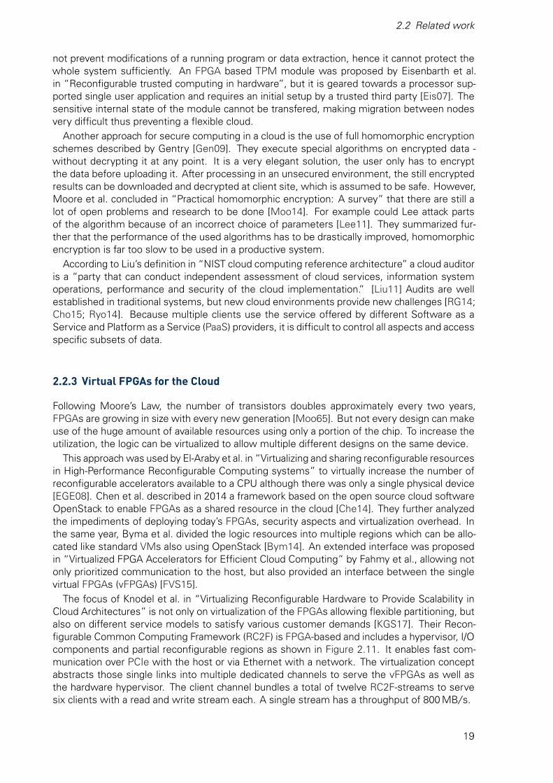
The focus of Knodel et al. in “Virtualizing Reconfigurable Hardware to Provide Scalability inCloud Architectures” is not only on virtualization of the FPGAs allowing flexible partitioning, butalso on different service models to satisfy various customer demands [KGS17]. Their Recon-figurable Common Computing Framework (RC2F) is FPGA-based and includes a hypervisor, I/Ocomponents and partial reconfigurable regions as shown in Figure 2.11. It enables fast com-munication over PCIe with the host or via Ethernet with a network. The virtualization conceptabstracts those single links into multiple dedicated channels to serve the vFPGAs as well asthe hardware hypervisor. The client channel bundles a total of twelve RC2F-streams to servesix clients with a read and write stream each. A single stream has a throughput of 800 MB/ s.
19

2 Background and Related Work
JTAGFlashBBRAM
ChannelInterface
PCIe Core Dom0 Hypervisor Virtualization Layer
Reconfig Area 1: vFPGA 0 Reconfig Area N: vFPGA N
PCI-Express Endpoint
Hypervisor Control Unit
Config SpaceSystem StatusReconfiguration
vFPGAControl Unit
ClockingState TransitionsIPv4-Address
Accelerator Design — DomU Accelerator Design — DomU…
||||||||||
Ethernet
Eth Core
PCI Virtualization VLAN/IP
||||||||||
64
vControl Config SpaceVirtual States
||||||||||
||||||||||
vControlConfig SpaceVirtual States
32
hoststream
netpacket
3264 64 64
hoststream
netpacket
3232
… …
Memory Core
Memory Controller
Memory Virtualization (Pagetable)
256256
256
ICAP Config
EncryptionUnit
AES, RSA, SHA
DDR3 RAM
FPGA Board
Network
Host
BackendInterface
FrontendInterface
HardwareInterface
Channel Virtualization……
Figure 2.11: The RC2F connects vFPGAs with a host over PCIe or with a network over Ethernet.It enables partial reconfiguration of individual regions. [KGS17]
2.2.4 FPGA Security Concepts
The before mentioned proposals focused on enabling FPGAs in the cloud, but they neglectedmajor security concerns. Although software offers a larger attack surface than hardware, dueto their complex multi tasking and resource sharing, FPGAs and their configuration are stillvulnerable to certain attacks and multiple security concerns arise.
First of all, the client’s system designer cannot be sure that the chip is free of hardwareTrojans, either the FPGA vendor or the foundries could have added them. However, Agrawal etal. investigated in “Trojan Detection using IC Fingerprinting” how the vendor can detect hiddenbackdoors using methods from cryptanalysis like power and temperature profiling to create aunique fingerprint for the IC [Agr07]. To generate such a fingerprint, only a few chips have tobe invasively tested if they comply with the vendor’s specifications. In 2012 a backdoor, whichleaked security keys among others, was detected in a military grade Actel/Mircosemi FPGA bySkorobogatov and Woods [SW12].
Thompson challenges the basic trust in software in “Reflections on trusting trust” [Tho84].The EDA tools themselves could extract information or manipulate the developers designs. Thisbasic problem directly affects all approaches on security and is not within the scope of thisthesis. Meanwhile, a strong reputation of the EDA tools developer might ease the concerns ofclients.
20
2.2 Related work
Operating FPGAs or other hardware under direct control of the client is fairly secure, e.g. fire-walls can prevent any data leakage. Yet, many FPGAs are deployed in the field and the systemdesigner looses direct physical access to secure the system. It has to withstand attempts ofreverse engineering, cloning or overbuilding among others. Leading manufactures are awareof such threats and attacks and provide tools to secure the valuable intellectual property (IP)[Tri07; UG470]. However, these systems have their shortcomings and are targeted at specificuse cases. Trimberger and Moore outlines possible attacks in [TM14]. For example, the de-crypted design could be intercepted while it configures the FPGA. Side-channel attacks likepower, timing and electromagnetic emanation analysis can be used to weaken the protectionfrom encryption. Timing based [Bha09], optical [SA03] or EM [SH07] fault injections can breakthe security of the chip as well. But again, there are effective defenses in place to protect thechip which were summarized in “A survey on security and trust of FPGA-based systems” byZhang and Qu [ZQ14].
2.2.5 Approaches on Security of Remote FPGAs
If the engineer has access to the devices before they are deployed, effective security mea-sures can be taken. This process is supported by many vendors as outlined in section 2.2.4.But in a cloud environment where the Infrastructure as a Service (IaaS) provider cannot betrusted, it is impossible for the client to establish any trust. Therefore, third party entities, of-ten called trusted authority (TA), are employed in different proposals to deploy a secured initialconfiguration. Drimer and Kuhn [DK09] and Devic et al. [DTB10] describe both a protocol forsecure remote updates which could also be used in the cloud context. They require additionalNon-Volatile-Memory and the first configuration is done in a trusted environment. Kepa et al.proposed in “Serecon: A secure dynamic partial reconfiguration controller” a few enhance-ments to the FPGA fabric to allow for a secure controller with a strong chain of trust [Kep08]. Athird party TA is utilized to certify the public key generated by the controller. They mediate ac-cess to the internal reconfiguration port to prevent malicious configurations from altering theircontroller. But slow asymmetric encryption, involvement of a host computer and no authenti-cation of the client’s bitstream are weak points. Another single user framework was proposedby Eguro and Venkatesan [EV12]. With the example of medical data they described how a TAwould configure FPGAs with symmetric keys before they are delivered to the data center. After-wards, clients send their design to the TA for encryption. Only the trustworthy preconfiguredFPGA can decrypt and partially reconfigure itself. They point out the difficulties of a securemulti user approach because of route-through wires to hard macros or I/O pins which have tobe protected from an adversary.
But employing a TA just transfers the trust problem from one party to another, the number ofinvolved and trusted participants does not change from the clients perspective. Furthermore,none of the proposals utilize the available fabric efficiently because they do not enable multipleusers.
21

3 DesignA small company wants to accelerate their data processing. Instead of buying expensiveservers and recruiting new personal to run them, they decide to use remote computing capabil-ities, the cloud. As they handle confidential data for their clients a public cloud cannot be used.It would make the data accessible to many different parties like data center administrators orthe PaaS provider, which are possible security flaws. To exclude these, dedicated hardware isrequired to bypass vulnerable and easy to manipulate software. Hence, it must be possible toestablish a secure connection to the device itself. Additionally, it must be authenticatable, thesmall company has to be able to verify the endpoint before sending sensitive data. After theconnection has been set up, a high throughput is required to process large amounts of data.Their algorithms also have a high memory complexity, external but secure remote storage isnecessary.
The cloud provider, on the other hand, has a different perspective. There, the device is anextra resource that has to be flexible, scalable and rapidly provisioned like other cloud resourcessuch as storage, CPUs or GPGPUs. These properties can be achieved through virtualization ofthe reconfigurable fabric into resizable partitions. But the management overhead for the hostsystem should be as low as possible, the more work can be offloaded to the device, the better.
This chapter discusses a possible solution and outlines decisions to meet the goal of an FPGAbased remote but secure and virtualized hardware accelerator in the cloud. The design has tosatisfy the demands of both client and provider. First, in section 3.1 the security requirementsare analyzed by classifying different levels of attacks, followed an evaluation of trust needed.This is used in the design of the hypervisor discussed in section 3.3. The chapter is concludedwith an evaluation of possible ways to realized the design in hardware.
3.1 Threat Model
To design a secure, remote endpoint for clients, different levels of adversaries and threats haveto be analyzed first. The primary concern is the confidentiality of the clients’ data and algorithms.Hence, slow downs, denial of service attacks or even physical destruction are not evaluated.
Level 5: Outside of the Data Center
A level five adversary is located outside of the data center and does not have any access to it,only the traffic to and from the client can be observed and altered. Therefore, the client mustbe able to establish an authenticated connection to the system. The connection has to be atleast as secure as other remote connections, e.g. to a trusted mail server.
23
3 Design
Level 4: Virtualized Access to the Same Host
A multitude of clients are active at the same time in a cloud system and not everyone isallocated a separate machine. Instead a few clients share a single host, which is virtualizedinto VMs by a VMM. Through security flaws in the virtualization layer, the device attached tothis host might be directly accessible to an attacker. However, the adversary could also be theIaaS provider. Therefore, the device has to protect itself and the clients’ data from unfilteredmalformed inputs.
Level 3: Physical Access to the Board
The device is considered to be under attack after it left the vendor’s facilities, hence the boardmanufacturer might be a threat. They could add compromising components, bugged memoryor unwanted external interfaces to the printed circuit board. Any third party in possession of itcan still alter it. Therefore, the board itself is treated as hostile and no unencrypted data canleave the device, unless explicitly sent by the user through a dedicated channel.
Level 2: Virtualized Access to the Same Physical Chip
At threat level two, a virtual partition on the same physical device is provisioned to the attacker.But it should not be possible to affect other users from within the device itself. Hence, sharedresources like network or memory bandwidth cannot be utilized to capacity by a single user.More importantly, a strict separation of the clients’ data is mandatory. Not only in memory orbuffers but the reconfigurable partitions must be isolated to prevent any interference, whichmight compromise the other clients’ security.
Level 1: Physical Access to the Chip
Since the board design cannot be relied on to protect the data, the device itself has to besecured. A threat-level-one attacker could get access to the device at any stage after it leftthe vendor’s facility. This includes transport service, board manufacturer and also data centerpersonal among others. They could, for example, try to extract important secret keys throughside-channel attacks. This is necessary because all encrypted data is assumed to be securewithout access to the keys if intact cryptographic schemes are used. Thus, the device has tobe hardened against physical attacks which would yield the cryptographic keys.
Level 0: Access During Design or Manufacturing
At threat level zero the attacker can alter the design or introduce backdoors during manufactur-ing. As outlined in section 2.2.4, the device vendor can analyze the hardware to find unwantedmodifications. Therefore, the client still has to trust the vendor, the tools and to some extendthe device foundry. But this is the same level of trust the client has to have into hardwarein general, CPUs, hard drives and other components might be modified as well. Hence, thesystem design does not aim to protect from threat-level-zero adversaries. After all, no remotesystem, which was never physically checked and controlled by the user, can be trusted.
3.2 Trust Model
No user of any remote system has total control over it contrary to classic in-house deploymentshown in Figure 3.1. In the later scenario, not even data leaking hardware Trojans are of anyconcern because any network access can be physically prevented or fully controlled by firewalls.
24
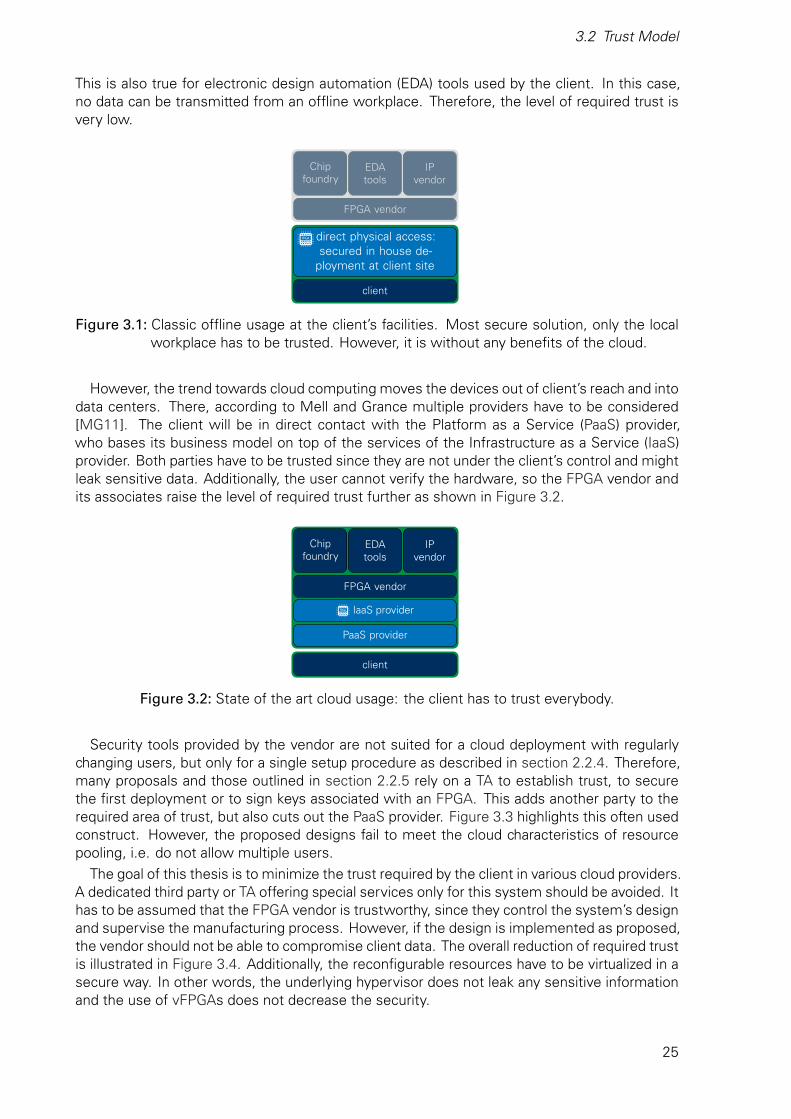
3.2 Trust Model
This is also true for electronic design automation (EDA) tools used by the client. In this case,no data can be transmitted from an offline workplace. Therefore, the level of required trust isvery low.
FPGA vendor
Chipfoundry
EDAtools
IPvendor
direct physical access:secured in house de-
ployment at client site
client
Figure 3.1: Classic offline usage at the client’s facilities. Most secure solution, only the localworkplace has to be trusted. However, it is without any benefits of the cloud.
However, the trend towards cloud computing moves the devices out of client’s reach and intodata centers. There, according to Mell and Grance multiple providers have to be considered[MG11]. The client will be in direct contact with the Platform as a Service (PaaS) provider,who bases its business model on top of the services of the Infrastructure as a Service (IaaS)provider. Both parties have to be trusted since they are not under the client’s control and mightleak sensitive data. Additionally, the user cannot verify the hardware, so the FPGA vendor andits associates raise the level of required trust further as shown in Figure 3.2.
FPGA vendor
Chipfoundry
EDAtools
IPvendor
IaaS provider
PaaS provider
client
Figure 3.2: State of the art cloud usage: the client has to trust everybody.
Security tools provided by the vendor are not suited for a cloud deployment with regularlychanging users, but only for a single setup procedure as described in section 2.2.4. Therefore,many proposals and those outlined in section 2.2.5 rely on a TA to establish trust, to securethe first deployment or to sign keys associated with an FPGA. This adds another party to therequired area of trust, but also cuts out the PaaS provider. Figure 3.3 highlights this often usedconstruct. However, the proposed designs fail to meet the cloud characteristics of resourcepooling, i.e. do not allow multiple users.
The goal of this thesis is to minimize the trust required by the client in various cloud providers.A dedicated third party or TA offering special services only for this system should be avoided. Ithas to be assumed that the FPGA vendor is trustworthy, since they control the system’s designand supervise the manufacturing process. However, if the design is implemented as proposed,the vendor should not be able to compromise client data. The overall reduction of required trustis illustrated in Figure 3.4. Additionally, the reconfigurable resources have to be virtualized in asecure way. In other words, the underlying hypervisor does not leak any sensitive informationand the use of vFPGAs does not decrease the security.
25
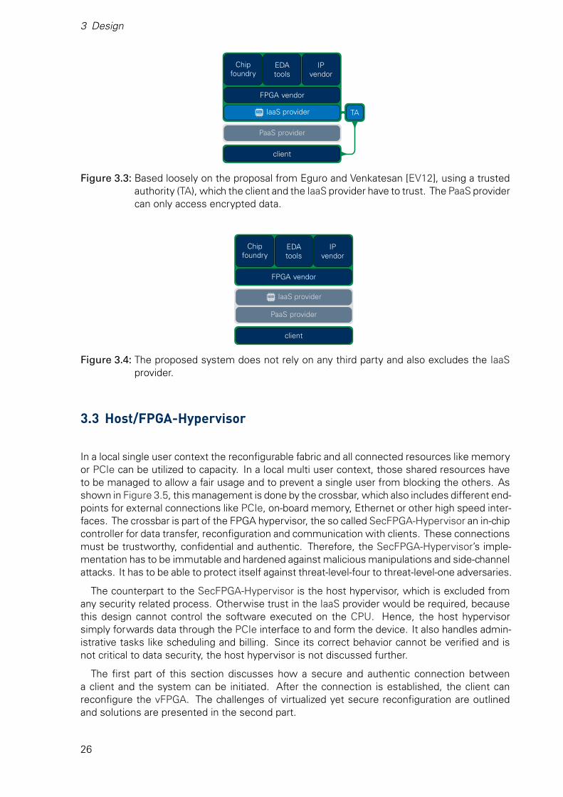
3 Design
FPGA vendor
Chipfoundry
EDAtools
IPvendor
IaaS provider
PaaS provider
client
TA
Figure 3.3: Based loosely on the proposal from Eguro and Venkatesan [EV12], using a trustedauthority (TA), which the client and the IaaS provider have to trust. The PaaS providercan only access encrypted data.
FPGA vendor
Chipfoundry
EDAtools
IPvendor
IaaS provider
PaaS provider
client
Figure 3.4: The proposed system does not rely on any third party and also excludes the IaaSprovider.
3.3 Host/FPGA-Hypervisor
In a local single user context the reconfigurable fabric and all connected resources like memoryor PCIe can be utilized to capacity. In a local multi user context, those shared resources haveto be managed to allow a fair usage and to prevent a single user from blocking the others. Asshown in Figure 3.5, this management is done by the crossbar, which also includes different end-points for external connections like PCIe, on-board memory, Ethernet or other high speed inter-faces. The crossbar is part of the FPGA hypervisor, the so called SecFPGA-Hypervisor an in-chipcontroller for data transfer, reconfiguration and communication with clients. These connectionsmust be trustworthy, confidential and authentic. Therefore, the SecFPGA-Hypervisor’s imple-mentation has to be immutable and hardened against malicious manipulations and side-channelattacks. It has to be able to protect itself against threat-level-four to threat-level-one adversaries.
The counterpart to the SecFPGA-Hypervisor is the host hypervisor, which is excluded fromany security related process. Otherwise trust in the IaaS provider would be required, becausethis design cannot control the software executed on the CPU. Hence, the host hypervisorsimply forwards data through the PCIe interface to and form the device. It also handles admin-istrative tasks like scheduling and billing. Since its correct behavior cannot be verified and isnot critical to data security, the host hypervisor is not discussed further.
The first part of this section discusses how a secure and authentic connection betweena client and the system can be initiated. After the connection is established, the client canreconfigure the vFPGA. The challenges of virtualized yet secure reconfiguration are outlinedand solutions are presented in the second part.
26

3.3 Host/FPGA-Hypervisor
Accelerator board
SecFPGA
endpoints &crossbar
hand-shake
PRE
keystore key gen
chip
on-board memory
external high speed interfaces
vFPGA 0
vFPGA 1
vFPGA 2
reco
nfigu
rabl
ech
ipar
ea
EE
EE
EE
...
...
...
key transfer data transfer reconfiguration immutable
Figure 3.5: High level overview of the proposed system. The SecFPGA-Hypervisors in dark bluemust be immutable to prevent malicious modifications compromising the security.The partial reconfiguration engine (PRE) enables changes to the configuration of thevirtual FPGA (vFPGA), whose data is protected by the encryption engines (EEs).
3.3.1 Initializing a Secure Connection
With available schemes it appears easy to secure a communication channel. Asymmetric cryp-tography allows two parties to make a confidential connection. The authenticity of the otherentity can be verified through a trusted third party. After that, symmetric keys are exchangedto increase the throughput. But a naive implementation of this straightforward process is stillsusceptible to different kinds of attacks, which are even available to a threat-level-five adver-sary. Hence, a more sophisticated protocol is mandatory to establish a reliable, confidentialand authentic connection.
This is not a new requirement, so different protocols can be found in the literature. Manyof them have matured over multiple versions to better withstand against different kinds ofattacks. For example, in the TLS protocol both client and server have to send random data,which is used among others to derive the shared secret keys. This makes attacks on weaksources of randomness on either side more difficult. Therefore, this design is based on alreadyexisting protocols to avoid possible vulnerabilities. One of them, TLS, was specifically designedfor (web)server-client connections. Thus, it will be adapted and used for every connection,overcoming the initial lack of trust in a remote system. If the handshake is directly implementedin hardware, vulnerable software can be bypassed and the attack surface is minimized. Thisincreases the security and causes little to no overhead on the host machine because it doesnot have to negotiate with the client itself. However, as outlined in section 2.1.7, the TLSprotocol allows a wide variety of key exchange, signature, MAC and bulk encryption algorithms.In contrary to software, the available area of a hardware implementation is limited and costly.Thus, only a fixed subset of primitives can be offered to a client.
The choice of those primitives is discussed in the following sections starting with the bulk en-cryption algorithm. Afterwards, different key exchange schemes are discussed, section 3.3.1.3approaches the authentication of a SecFPGA and 3.3.1.4 evaluates various message authenti-cation codes. The final section 3.3.1.5 describes the bitstream transfer protocol.
27
3 Design
3.3.1.1 Data Encryption
The selection of an encryption algorithm is crucial for the performance of the system, since ev-ery byte of data entering or leaving the client’s vFPGA has to be processed. Hence, asymmetricschemes cannot be used, they are neither fast nor designed for encrypting long streams of data.Symmetric algorithms, on the other hand, offer superior performance, a smaller area footprintand shorter keys. But they are not all the same, several symmetric encryption schemes wereoutlined in section 2.1.1 and compared in Table 2.3. Key size, the primary factor for the pro-vided security level, can vary from 128 to 256 bit for most primitives. This allows for differentlevels of security without a new algorithm. However, KASUMI only allows for 128-bit keys,locking the security level. Additionally, a practical attack is known, which increases the likeli-hood of new even more compromising attacks leading to a complete break of the algorithm.The other schemes do not show such weaknesses and, at the same time, offer higher perfor-mance. If only throughput has to be considered, ChaCha20 would be the algorithm of choicefor a hardware implementation. But chip area and client performance, most likely CPU bound,are important as well. There, AES provides better speed per area and thanks to CPU extensionslike AES-NI unmatched client side performance. Since ChaCha20 is a relatively new algorithm,improved implementations and dedicated CPU might become available in the future. Twofishis to slow overall to be a viable option.
In summary, AES is a flexible, secure and on every platform fast option and is thereforeselected as the data encryption algorithm.
3.3.1.2 Sharing a Common Secret
To use a symmetric encryption scheme, both parties have to use the same shared key. Trans-mitting this key without any protection would render the encryption useless since an attackercould easily extract the key and decrypt the data. Therefore, both parties have to establish acommon secret which cannot be accessed by anyone else.
One option is asymmetric encryption with RSA described in section 2.1.2.1. The client gen-erates the symmetric key, encrypts it with the public key of the server and transmits it overthe unsecured channel. Since only the server has access to the private key, no third party candecrypt the symmetric key. This method is an often used option in the TLS handshake protocol(section 2.1.7). Another possible option is the ECDH key exchange outlined in section 2.1.2.4.It has several advantages over RSA, some of which are summarized in Table 2.4. The generalperformance of the basic operation is faster with elliptic curves in terms of CPU cycles as wellas with FPGAs. There, also the resource usage is less and the smaller keys allow for a moreefficient design. Another advantage is easier perfect forward secrecy. With RSA, generating anew public key for every connection takes time, especially on an embedded hardware [LSP02].Also, ephemeral RSA (ERSA) is not supported by TLS. Elliptic curves, on the other hand, allowfor a very fast public key generation and ECDH(E) is fully supported by TLS.
Many different elliptic curves are defined, but the SecFPGA can only support one specificcurve due to resource constraints. It can be assumed that the client does know which curve issupported and therefore sends the suitable public key share as soon as a device was allocated.It can not be assumed though that the client knows all public keys of all devices within the datacenter. If the symmetric key should be shared with RSA, the client has to acquire the specificpublic key first, which adds an extra round trip.
In summary, ECDHE allows for easier implementations of perfect forward secrecy, fasterhandshakes and shorter keys, all in all enabling a more efficient design.
28
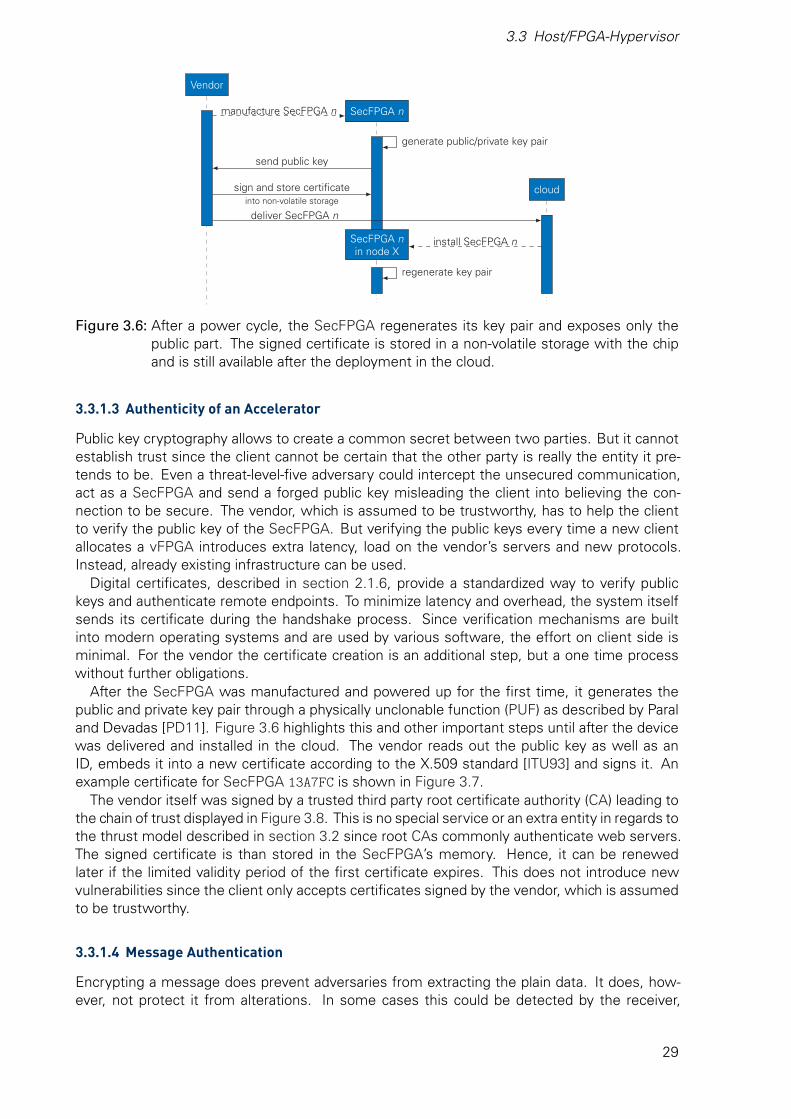
3.3 Host/FPGA-Hypervisor
Vendor
SecFPGA n
SecFPGA nin node X
cloud
manufacture SecFPGA n
generate public/private key pair
send public key
sign and store certificateinto non-volatile storage
deliver SecFPGA n
install SecFPGA n
regenerate key pair
Figure 3.6: After a power cycle, the SecFPGA regenerates its key pair and exposes only thepublic part. The signed certificate is stored in a non-volatile storage with the chipand is still available after the deployment in the cloud.
3.3.1.3 Authenticity of an Accelerator
Public key cryptography allows to create a common secret between two parties. But it cannotestablish trust since the client cannot be certain that the other party is really the entity it pre-tends to be. Even a threat-level-five adversary could intercept the unsecured communication,act as a SecFPGA and send a forged public key misleading the client into believing the con-nection to be secure. The vendor, which is assumed to be trustworthy, has to help the clientto verify the public key of the SecFPGA. But verifying the public keys every time a new clientallocates a vFPGA introduces extra latency, load on the vendor’s servers and new protocols.Instead, already existing infrastructure can be used.
Digital certificates, described in section 2.1.6, provide a standardized way to verify publickeys and authenticate remote endpoints. To minimize latency and overhead, the system itselfsends its certificate during the handshake process. Since verification mechanisms are builtinto modern operating systems and are used by various software, the effort on client side isminimal. For the vendor the certificate creation is an additional step, but a one time processwithout further obligations.
After the SecFPGA was manufactured and powered up for the first time, it generates thepublic and private key pair through a physically unclonable function (PUF) as described by Paraland Devadas [PD11]. Figure 3.6 highlights this and other important steps until after the devicewas delivered and installed in the cloud. The vendor reads out the public key as well as anID, embeds it into a new certificate according to the X.509 standard [ITU93] and signs it. Anexample certificate for SecFPGA 13A7FC is shown in Figure 3.7.
The vendor itself was signed by a trusted third party root certificate authority (CA) leading tothe chain of trust displayed in Figure 3.8. This is no special service or an extra entity in regards tothe thrust model described in section 3.2 since root CAs commonly authenticate web servers.The signed certificate is than stored in the SecFPGA’s memory. Hence, it can be renewedlater if the limited validity period of the first certificate expires. This does not introduce newvulnerabilities since the client only accepts certificates signed by the vendor, which is assumedto be trustworthy.
3.3.1.4 Message Authentication
Encrypting a message does prevent adversaries from extracting the plain data. It does, how-ever, not protect it from alterations. In some cases this could be detected by the receiver,
29
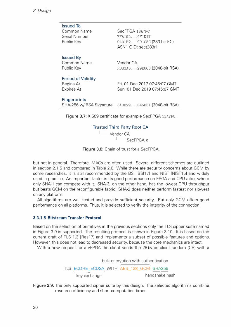
3 Design
Issued ToCommon Name SecFPGA 13A7FCSerial Number 7FA192...4F1D17Public Key 0401B2...9D1C5C (283-bit EC)
ASN1 OID: sect283r1
Issued ByCommon Name Vendor CAPublic Key FDB3A3...29E6C3 (2048-bit RSA)
Period of ValidityBegins At Fri, 01 Dec 2017 07:45:07 GMTExpires At Sun, 01 Dec 2019 07:45:07 GMT
FingerprintsSHA-256 w/ RSA Signature 3ABD29...E46B51 (2048-bit RSA)
Figure 3.7: X.509 certificate for example SecFPGA 13A7FC.
Trusted Third Party Root CA
Vendor CASecFPGA n
Figure 3.8: Chain of trust for a SecFPGA.
but not in general. Therefore, MACs are often used. Several different schemes are outlinedin section 2.1.5 and compared in Table 2.6. While there are security concerns about GCM bysome researches, it is still recommended by the BSI [BSI17] and NIST [NIST15] and widelyused in practice. An important factor is its good performance on FPGA and CPU alike, whereonly SHA-1 can compete with it. SHA-3, on the other hand, has the lowest CPU throughputbut bests GCM on the reconfigurable fabric. SHA-2 does neither perform fastest nor sloweston any platform.
All algorithms are well tested and provide sufficient security. But only GCM offers goodperformance on all platforms. Thus, it is selected to verify the integrity of the connection.
3.3.1.5 Bitstream Transfer Protocol
Based on the selection of primitives in the previous sections only the TLS cipher suite namedin Figure 3.9 is supported. The resulting protocol is shown in Figure 3.10. It is based on thecurrent draft of TLS 1.3 [Res17] and implements a subset of possible features and options.However, this does not lead to decreased security, because the core mechanics are intact.
With a new request for a vFPGA the client sends the 28 bytes client random (CR) with a
TLS ECDHE ECDSA WITH AES 128 GCM SHA256
key exchange
bulk encryption with authentication
handshake hash
Figure 3.9: The only supported cipher suite by this design. The selected algorithms combineresource efficiency and short computation times.
30

3.3 Host/FPGA-Hypervisor
clientSecFPGA nin node X
vFPGA m inSecFPGA n
vFPGA requestclient random (CR) & key share (CKS)
reset requested vFPGA m
generate ECDHE-keys: SPK, SKSsym = PRNG(CR, ECDH(CKS, SPK), SR)
session random (SR) & SKS|certificate & |“verfiy”hash|DPRK & “final” hash|sym
sym = PRNG(CR, ECDH(SKS, CPK), SR)verify certificateverify hash
|client’s “final” hash & bitstream|sym decrypt, verfiy and program bitstream
Figure 3.10: The TLS protocol was adapted to enable the secure and authentic transfers ofvFPGA bitstreams to a SecFPGA. The configuration is protected by symmetricencryption with the key “sym”, which is created during the TLS handshake.
client key share (CKS) suitable for the implemented elliptic curve. The host hypervisor canevaluate the unencrypted request for billing and scheduling and afterwards forward them tothe SecFPGA. If the request is unjustly blocked by a cloud provider or evicts another legitimateclient, only their quality of service suffers, but not the security of clients’ data. Through acomplete reset of the vFPGA previous configurations are no longer accessible, and even if dataremains in buffers or external memory it is still encrypted.
After the vFPGA reset, the true random number generator (TRNG), which is part of theSecFPGA, generates 28 bytes session random (SR) and an ephemeral session private key (SPK).With the SPK the public session key share (SKS) is calculated. This new key pair is used to com-plete the ECDHE key exchange. The resulting shared secret is along with the CR and SR feedinto a well defined pseudo random number generator (PRNG). Its output is used to derive var-ious symmetric keys (sym), which are right away utilized to encrypt the SecFPGA’s certificate.Additionally, a hash over the transaction so far is calculated, signed through the ECDSA withthe device private key, encrypted and appended to the certificate. Finally, a second hash overthe whole handshake including the CR, CKS, SR, SKS, the encrypted certificate and first hashis calculated, then encrypted and the package is send to the client. Upon receiving it, the un-encrypted SR and SKS are used in the same way to derive the symmetric keys (sym) throughECDHE and the PRNG. With them, the rest can be decrypted, the certificate and public keyverified and the hashes checked. At last, the client also calculates a hash over the whole trans-action, now including the second hash, and prepends it to the bitstream. Together they areencrypted with sym and transfered to the SecFPGA. There, after the hash was compared to alocally computed one, the vFPGA bitstream is programmed and the partition ready for use.
If any errors occur or the client uses standardized but not implemented functionalities, thehandshake aborts, resets and returns the system into a safe state in which it accepts newconnections.
3.3.2 Robust Virtualization of Reconfigurable Logic
Partial dynamic reconfiguration enables systems like FPGAs to change their behavior at runtimein one area without interrupting operations in other areas [UG470]. This useful feature is usedby various proposals outline in section 2.2.3 and enables the creation of vFPGAs, partitionswithin the system, which are mediated by a hypervisor. That is made possible by a hard macro,the partial reconfiguration engine (PRE), a fixed component inside the chip to reconfigure itself.FPGAs allow almost every resource to be changed through the PRE, which can be connectedinternally or driven by external pins. To prevent adversaries from altering the configuration,
31
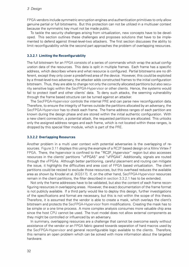
3 Design
FPGA vendors include symmetric encryption engines and authentication primitives to only allowgenuine partial or full bitstreams. But this protection can not be utilized in a multiuser contextbecause the symmetric key must not be made public.
To tackle the security challenges arising from virtualization, new concepts have to be devel-oped. This section outlines these challenges and proposes solutions that have to be imple-mented to defend against threat-level-two attackers. The first section discusses the ability tolimit reconfigurability while the second part approaches the problem of overlapping resources.
3.3.2.1 Limiting the Reconfigurability
The full bitstream for an FPGA consists of a series of commands which wrap the actual config-uration data of the resources. This data is split in multiple frames. Each frame has a specificaddress, which describes where and what resource is configured. Partial bitstreams are no dif-ferent, except they only cover a predefined area of the device. However, this could be exploitedby a threat-level-two adversary, the attacker adds constructed frames to the initial configurationbitstream. Thus, they are able to change not only the correctly allocated partitions but also secu-rity sensitive logic within the SecFPGA-Hypervisor or other clients. Hence, the systems wouldfail to protect itself and other clients’ data. To deny such attacks, the seeming vulnerabilitythrough the frame based structure can be turned against an attacker.
The SecFPGA-Hypervisor controls the internal PRE and can parse new reconfiguration data.Therefore, to ensure the integrity of frames outside the partitions allocated by an adversary, theSecFPGA-Hypervisor has to check each frame. The frame address ranges of each partition areknown during the design phase and are stored within the initial authentic configuration. Witha new client connection, a potential attack, the requested partitions are allocated. This unlocksonly the assigned address ranges and each frame, which is not located within these ranges, isdropped by this special filter module, which is part of the PRE.
3.3.2.2 Overlapping Resources
Another problem in a multi user context with potential adversaries is the overlapping of re-sources. Figure 3.11 displays this using the example of a RC2F based design on a Xilinx Virtex-7FPGA. There, the hypervisor is confined to the “RC2F_Hypervisor” region but also accessesresources in the clients’ partitions “vFPGA5” and “vFPGA4”. Additionally, signals are routedthrough the vFPGAs. Although better partitioning, careful placement and routing can mitigatethe issue, it highlights the difficulties and area cost of FPGA based virtualization. The clientpartitions could be resized to exclude those resources, but this overhead reduces the availablearea as shown by Knodel et al. [KGS17]. If, on the other hand, SecFPGA-Hypervisor resourcesremain in the client partitions, the filter described in section 3.3.2.1 has to be extended.
Not only the frame addresses have to be validated, but also the content of each frame recon-figuring resources in overlapping areas. However, the exact documentation of the frame formatis not publicly available. If a third party would like to deploy this design, further investigationsof the specifications and format are necessary, but this is not within the scope of this thesis.Therefore, it is assumed that the vendor is able to create a mask, which overlays the client’sbitstream and protects the SecFPGA-Hypervisor from modifications. Creating the mask has tobe simple or a one time process. A more complex analysis consumes more valuable chip areasince the host CPU cannot be used. The trust model does not allow external components asthey might be controlled or influenced by an adversary.
In summary, overlapping resources are a challenge that cannot be overcome easily withoutassistance of the vendor or an FPGA fabric geared towards separation of hard macros used bythe SecFPGA-Hypervisor and general reconfigurable logic available to the clients. Therefore,this remains an open problem which can be solved with more information about the targetedhardware.
32
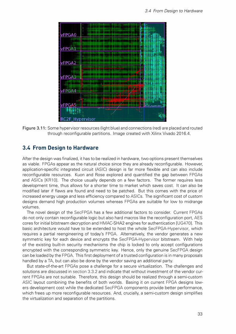
3.4 From Design to Hardware
Figure 3.11: Some hypervisor resources (light blue) and connections (red) are placed and routedthrough reconfigurable partitions. Image created with Xilinx Vivado 2016.4.
3.4 From Design to Hardware
After the design was finalized, it has to be realized in hardware, two options present themselvesas viable. FPGAs appear as the natural choice since they are already reconfigurable. However,application-specific integrated circuit (ASIC) design is far more flexible and can also includereconfigurable resources. Kuon and Rose explored and quantified the gap between FPGAsand ASICs [KR10]. The choice usually depends on a few factors. The former requires lessdevelopment time, thus allows for a shorter time to market which saves cost. It can also bemodified later if flaws are found and need to be patched. But this comes with the price ofincreased energy usage and less efficiency compared to ASICs. The significant cost of customdesigns demand high production volumes whereas FPGAs are suitable for low to midrangevolumes.
The novel design of the SecFPGA has a few additional factors to consider. Current FPGAsdo not only contain reconfigurable logic but also hard macros like the reconfiguration port, AEScores for initial bitstream decryption and HMAC-SHA2 engines for authentication [UG470]. Thisbasic architecture would have to be extended to host the whole SecFPGA-Hypervisor, whichrequires a partial reengineering of today’s FPGA. Alternatively, the vendor generates a newsymmetric key for each device and encrypts the SecFPGA-Hypervisor bitstream. With helpof the existing built-in security mechanisms the chip is locked to only accept configurationsencrypted with the corresponding symmetric key. Hence, only the genuine SecFPGA designcan be loaded by the FPGA. This first deployment of a trusted configuration is in many proposalshandled by a TA, but can also be done by the vendor saving an additional party.
But state-of-the-art FPGAs pose a challenge for a secure virtualization. The challenges andsolutions are discussed in section 3.3.2 and indicate that without investment of the vendor cur-rent FPGAs are not suitable. Therefore, this design should be realized through a semi-customASIC layout combining the benefits of both worlds. Basing it on current FPGA designs low-ers development cost while the dedicated SecFPGA components provide better performance,which frees up more reconfigurable resources. And, crucially, a semi-custom design simplifiesthe virtualization and separation of the partitions.
33

4 SecFPGA-Hypervisor ImplementationIn this chapter an implementation of the SecFPGA-Hypervisor design discussed in chapter 3 isdescribed. The RC2F, outlined in section 2.2.3, is used as the base of this implementation. Itsupports important functionality like data transfer over PCIe, memory virtualization and Ethernetcommunication. A host hypervisor is also available to assist in a fast development. The RC2Fis extended with a prototype of the SecFPGA-Hypervisor to perform necessary operations toallow for a secure and authentic transfer of a vFPGA bitstream. To enable this initial handshake,the SecFPGA-Hypervisor is divided into five modules and acts like a proxy in the RC2F as shownin Figure 4.1. The RC2F System Bus is connected to the host via PCIe. The system channelof the bus handles management data and the vFPGA bitstreams whereas the client channelis dedicated for communication with the vFPGAs after the initial handshake. At the other sideof the SecFPGA-Hypervisor, the RC2F vFPGA Bus connects to the PRE of the FPGA, which isconnected through the RC2F. The client channel on the RC2F vFPGA Bus transfers unencrypteddata between the SecFPGA-Hypervisor and the clients’ vFPGAs.
The interaction of the SecFPGA-Hypervisor modules is shown in Figure 4.2. The sequencefollows the design of the handshake discussed in section 3.3.1.5 closely. Internal details of themodules and their interfaces are described in this chapter. First, the startup and precomputa-tion phase, which mainly involves the SecFPGA-Hypervisor’s EC Key Processor, is depicted insection 4.1. Afterwards, the Command (CMD) Decoder is described in section 4.2 followedby the Key Store in 4.3. After the connection to the client is secured, the received bitstreamhas to be analyzed. A description of the Configuration Filter is given in section 4.4. Finally, theencryption and decryption of the clients’ data is outlined in section 4.5
Internal BusEC Key
Processor
CommandDecoder
Key Storesymmetric keys
symmetric noncesMAC keys
ConfigurationFilter
Encryption
Decryption
RC2F System Bus RC2F vFPGA Bus
system
client client
config
SecFPGA-Hypervisor
Figure 4.1: The SecFPGA-Hypervisor acts like a proxy between the RC2F System and vFPGABus. The internal bus is a representation of the TLS key distribution.
35
4 SecFPGA-Hypervisor Implementation
Implementing efficient, high speed cryptographic schemes is not part of this thesis. Thepurpose of this prototype is to verify the design of chapter 3, hence only critical aspects arerealized. Some elements like AES-GCM are replaced with other algorithms, because publiclyavailable cores have insufficient performance. All implemented cores are also not hardenedagainst a threat-level-one attacker. The design is implemented with Vivado 2016.4 and targetsthe Virtex-7 VC707 Evaluation Platform1, which is equipped with a Xilinx XC7VX485TFFG1761-2[DS180].
4.1 EC Key Processor
The EC (Elliptic Curve) Key Processor handles the asymmetric cryptography operations insidethe SecFPGA-Hypervisor. With a state machine build around the elliptic curve multiplier (ECM),the EC Key Processor enables the ECDHE key exchange and signature generation throughECDSA. Several submodules are needed to provide this functionality as shown in Figure 4.3.The key generator is, however, not based on a PUF as described in section 3.3.1.3. In thisprototype it is a placeholder which provides a predefined value as private key. Hence, it is onlyconnected to the ECDSA core and not to the ECM, which would calculate the public key. Asshown in Figure 4.4, it is closely coupled with the Command Decoder, but the separation intosingle modules allows for a cleaner implementation and an easy exchange of the underlyingsecurity primitives.
To speed up the TLS handshake, the EC Key Processor starts several precomputations, whichinclude:
• Generation of an ephemeral session private key.
• Calculation of the session key share (SKS) based on the session private key.
• Generation of 8-byte session random data.
• Generation of the signature intermediate.
• Calculation of the signature curve point based on the intermediate.
Figure 4.5 visualizes those steps as possible states of the EC Key Processor and highlightsthe precomputation states with a dashed line. These operations primarily depend on the ECMdescribed in section 4.1.1. To generate new values a TRNG is utilized, which is outline in sec-tion 4.1.2. After the precomputation completes, the EC Key Processor waits for a client toconnect. The initial data package is processed by the CMD Decoder and the client key share(CKS) input is asserted. It is used by the ECM to complete the ECDHE key exchange and derivea common secret. Details of the key derivation are described in section 4.1.3. Following that,the “verify” hash of the transaction is processed by the ECDSA core to calculate the signature,which is explain further in section 4.1.4. Finally, the EC Key Processor enters an idle state untilthe CMD Decoder asserts a reset to start the precomputations for a new connection.
4.1.1 Elliptic Curve Multiplier
Elliptic curve arithmetic is the mathematical foundation of the security of this design. The el-liptic curve multiplier (ECM) handles multiplications on a specific curve. Implementing such aprocessor is not within the scope of this thesis, hence an already existing core was used. How-ever, it is optimized solely for the curve sept233r1 [Cer10] fixing the security level to 233 bits.According to Table 2.1, this is similar to about 112-bit AES and is in the same order of magni-tude as the other primitives. The processor itself was developed by Rebeiro and Mukhopadhyay
1https://www.xilinx.com/products/boards-and-kits/ek-v7-vc707-g.html
36

4.1 EC Key Processor
App
Com
man
dD
ecod
erE
CK
eyP
roce
ssor
Key
Sto
reC
onfig
urat
ion
Filte
r..
...
.
Sec
FPG
A-H
yper
viso
rC
lient
Inse
cure
Cha
nnel
cmd
0x00
clie
ntke
ysh
are
(CK
S)
clea
rre
ques
ted
vFP
GA
s
cmd
0x80
sess
ion
key
shar
e(S
KS
)cl
ient
key
shar
e(C
KS
)ca
lcul
ate
shar
edse
cret
deriv
eTL
S-k
eys
upda
teTL
Ske
ysfo
rre
ques
ted
slot
spr
ovid
eke
yan
dno
nce
encr
ypt
cert
ifica
te
“ver
ify”
hash
oftr
ansa
ctio
n
sign
hash
“ver
ify”
EC
DS
Asi
gant
ure
ofha
sh
encr
ypt
sign
atur
e
cmd
0x81
encr
ypte
dce
rtifi
cate
and
sign
atur
eco
mpu
te“fi
nal”
hash
encr
ypt
hash
cmd
0x82
encr
ypte
dha
shof
who
leha
ndsh
ake
upda
teS
ecFP
GA
_writ
e_no
nce
verif
yce
rtifi
cate
,han
dsha
ke
cmd
0x01
encr
ypte
dvF
PG
Abi
tstr
eam
decr
ypte
dvF
PG
Abi
tstr
eam
enab
lere
ques
ted
rang
esfil
tere
dfr
ames
toR
C2F
confi
g
upda
tecl
ient
_writ
e_no
nce
Figu
re4.
2:In
tera
ctio
nof
the
Sec
FPG
A-H
yper
viso
rmod
ules
with
each
othe
rand
with
acl
ient
over
anun
secu
red
chan
nel.
The
goal
isa
secu
red
and
auth
entic
vFP
GA
bits
trea
mtr
ansf
er.
Pre
com
puta
tion
ofin
term
edia
teE
CD
HE
and
EC
DS
Ava
riabl
esis
done
befo
reth
ecl
ient
conn
ects
othe
rwis
eth
ere
ques
tis
stal
led.
The
Sec
FPG
A’s
host
isno
tsh
own
beca
use
iton
lyfo
rwar
dsth
eda
taan
dis
part
ofth
ein
secu
rech
anne
l.
37
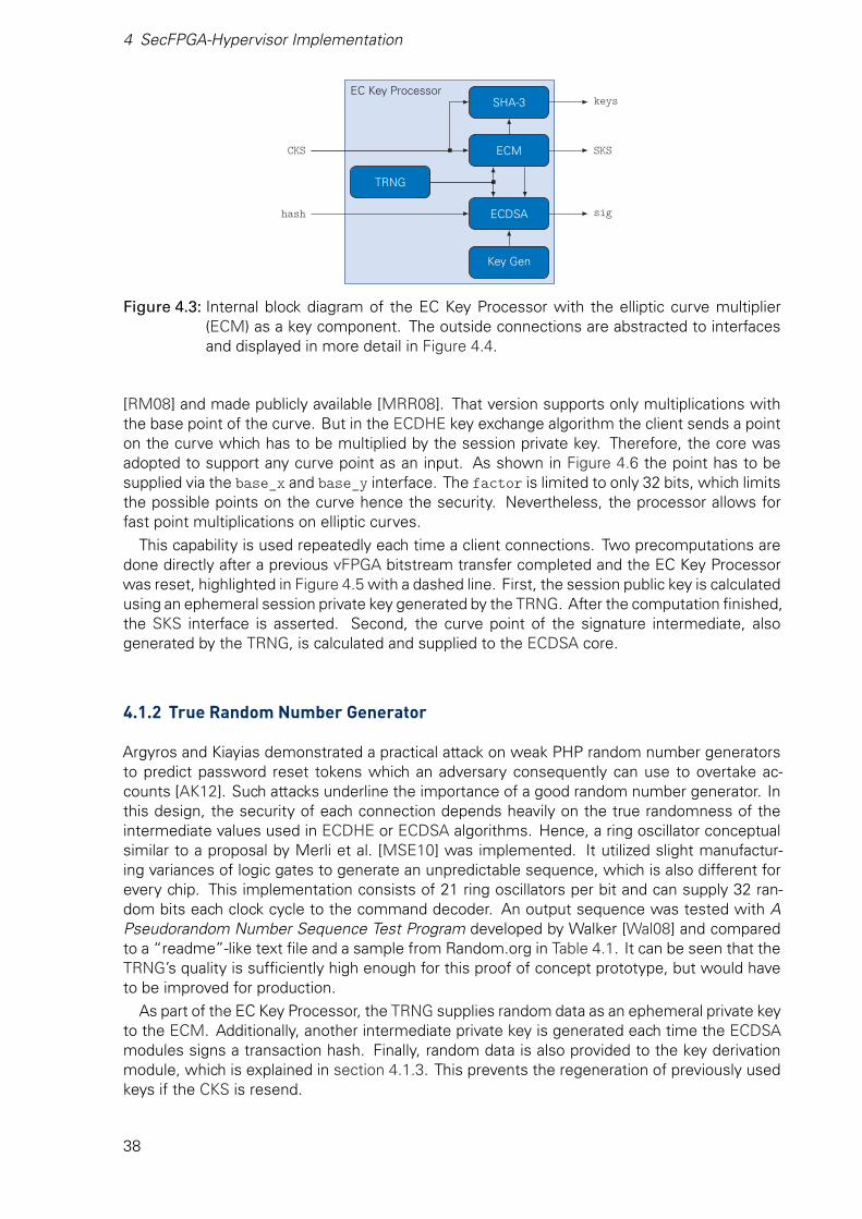
4 SecFPGA-Hypervisor Implementation
EC Key Processor
ECM
SHA-3
ECDSA
TRNG
Key Gen
hash
CKS SKS
sig
keys
Figure 4.3: Internal block diagram of the EC Key Processor with the elliptic curve multiplier(ECM) as a key component. The outside connections are abstracted to interfacesand displayed in more detail in Figure 4.4.
[RM08] and made publicly available [MRR08]. That version supports only multiplications withthe base point of the curve. But in the ECDHE key exchange algorithm the client sends a pointon the curve which has to be multiplied by the session private key. Therefore, the core wasadopted to support any curve point as an input. As shown in Figure 4.6 the point has to besupplied via the base_x and base_y interface. The factor is limited to only 32 bits, which limitsthe possible points on the curve hence the security. Nevertheless, the processor allows forfast point multiplications on elliptic curves.
This capability is used repeatedly each time a client connections. Two precomputations aredone directly after a previous vFPGA bitstream transfer completed and the EC Key Processorwas reset, highlighted in Figure 4.5 with a dashed line. First, the session public key is calculatedusing an ephemeral session private key generated by the TRNG. After the computation finished,the SKS interface is asserted. Second, the curve point of the signature intermediate, alsogenerated by the TRNG, is calculated and supplied to the ECDSA core.
4.1.2 True Random Number Generator
Argyros and Kiayias demonstrated a practical attack on weak PHP random number generatorsto predict password reset tokens which an adversary consequently can use to overtake ac-counts [AK12]. Such attacks underline the importance of a good random number generator. Inthis design, the security of each connection depends heavily on the true randomness of theintermediate values used in ECDHE or ECDSA algorithms. Hence, a ring oscillator conceptualsimilar to a proposal by Merli et al. [MSE10] was implemented. It utilized slight manufactur-ing variances of logic gates to generate an unpredictable sequence, which is also different forevery chip. This implementation consists of 21 ring oscillators per bit and can supply 32 ran-dom bits each clock cycle to the command decoder. An output sequence was tested with APseudorandom Number Sequence Test Program developed by Walker [Wal08] and comparedto a “readme”-like text file and a sample from Random.org in Table 4.1. It can be seen that theTRNG’s quality is sufficiently high enough for this proof of concept prototype, but would haveto be improved for production.
As part of the EC Key Processor, the TRNG supplies random data as an ephemeral private keyto the ECM. Additionally, another intermediate private key is generated each time the ECDSAmodules signs a transaction hash. Finally, random data is also provided to the key derivationmodule, which is explained in section 4.1.3. This prevents the regeneration of previously usedkeys if the CKS is resend.
38

4.1 EC Key Processor
clk
reset
client_pub_x session_key_x
client_pub_y session_key_y
client_random EC KeyProcessor
session_random
client_pub_valid session_key_valid
transaction_hash signature
transaction_hash_valid signature_valid
client_write_key
SecFPGA_write_key
client_write_nonce
SecFPGA_write_nonce
client_write_MAC_secret
SecFPGA_write_MAC_secret
keys_valid
CKS interfacefrom CMD Decoder
hash interfacefrom CMD Decoder
SKS interfaceto CMD Decoder
sig interfaceto CMD Decoder
keys interfaceto Key Store andCMD Decoder
233
233
64
233
233
233
64
466
128
128
128
128
128
128
Figure 4.4: Interface of the EC Key Processor. Various signals are grouped into sub-interfaces.
generate signa-ture intermediate
invert signatureintermediate
generate sessionprivate key
calculate sessionkey share
calculate signa-ture curve point
wait for clientkey share
calculateshared secret
derive key set 0
derive key set 1
wait for trans-action hash
calculate ECDSAsignature
finished
finished/assert SKS finished
finished
CKS asserted finished
finished
finished/assert keys
hash asserted
finished/assert sig
reset
precomputation
Figure 4.5: State machine of the EC Key Processor. The precomputations encircled by a dashedline can be done before a client connects. The signal interfaces are defined inFigure 4.4.
39
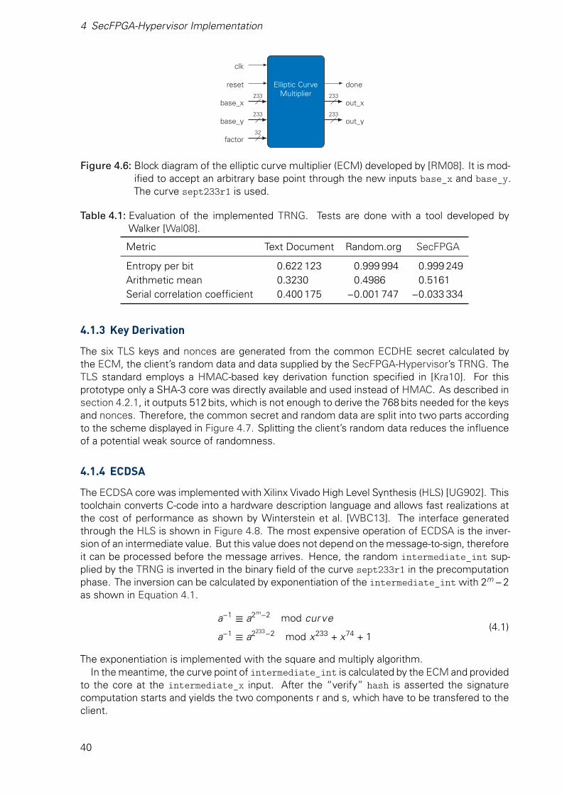
4 SecFPGA-Hypervisor Implementation
clk
reset Elliptic CurveMultiplier
done
base_x out_x
base_y out_y
factor
233
233
32
233
233
Figure 4.6: Block diagram of the elliptic curve multiplier (ECM) developed by [RM08]. It is mod-ified to accept an arbitrary base point through the new inputs base_x and base_y.The curve sept233r1 is used.
Table 4.1: Evaluation of the implemented TRNG. Tests are done with a tool developed byWalker [Wal08].
Metric Text Document Random.org SecFPGA
Entropy per bit 0.622 123 0.999 994 0.999 249Arithmetic mean 0.3230 0.4986 0.5161Serial correlation coefficient 0.400 175 −0.001 747 −0.033 334
4.1.3 Key Derivation
The six TLS keys and nonces are generated from the common ECDHE secret calculated bythe ECM, the client’s random data and data supplied by the SecFPGA-Hypervisor’s TRNG. TheTLS standard employs a HMAC-based key derivation function specified in [Kra10]. For thisprototype only a SHA-3 core was directly available and used instead of HMAC. As described insection 4.2.1, it outputs 512 bits, which is not enough to derive the 768 bits needed for the keysand nonces. Therefore, the common secret and random data are split into two parts accordingto the scheme displayed in Figure 4.7. Splitting the client’s random data reduces the influenceof a potential weak source of randomness.
4.1.4 ECDSA
The ECDSA core was implemented with Xilinx Vivado High Level Synthesis (HLS) [UG902]. Thistoolchain converts C-code into a hardware description language and allows fast realizations atthe cost of performance as shown by Winterstein et al. [WBC13]. The interface generatedthrough the HLS is shown in Figure 4.8. The most expensive operation of ECDSA is the inver-sion of an intermediate value. But this value does not depend on the message-to-sign, thereforeit can be processed before the message arrives. Hence, the random intermediate_int sup-plied by the TRNG is inverted in the binary field of the curve sept233r1 in the precomputationphase. The inversion can be calculated by exponentiation of the intermediate_int with 2m −2as shown in Equation 4.1.
a−1 ≡ a2m−2 mod curve
a−1 ≡ a2233−2 mod x233 + x74 + 1(4.1)
The exponentiation is implemented with the square and multiply algorithm.In the meantime, the curve point of intermediate_int is calculated by the ECM and provided
to the core at the intermediate_x input. After the “verify” hash is asserted the signaturecomputation starts and yields the two components r and s, which have to be transfered to theclient.
40
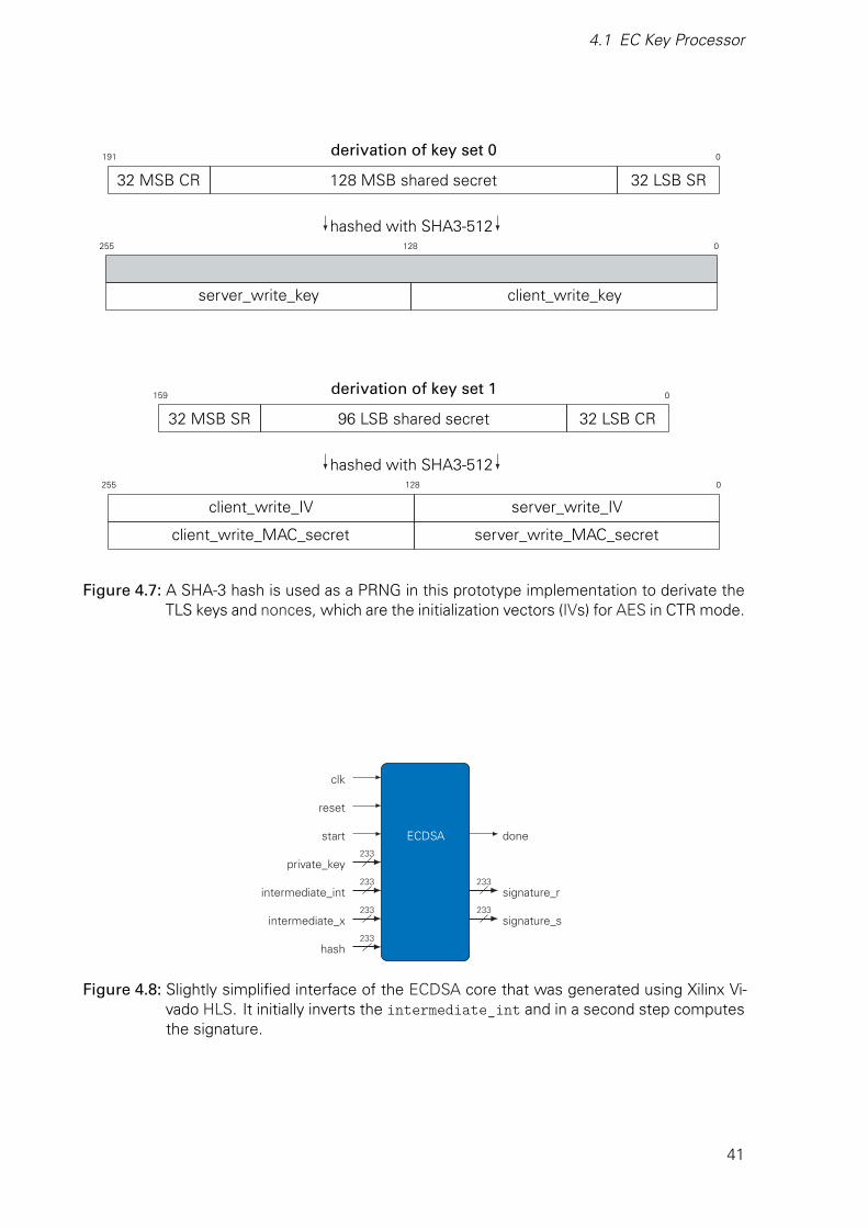
4.1 EC Key Processor
derivation of key set 0191 0
32 MSB CR 128 MSB shared secret 32 LSB SR
hashed with SHA3-512255 128 0
server_write_key client_write_key
derivation of key set 1159 0
32 MSB SR 96 LSB shared secret 32 LSB CR
hashed with SHA3-512255 128 0
client_write_IV server_write_IV
client_write_MAC_secret server_write_MAC_secret
Figure 4.7: A SHA-3 hash is used as a PRNG in this prototype implementation to derivate theTLS keys and nonces, which are the initialization vectors (IVs) for AES in CTR mode.
clk
reset
start ECDSA done
private_key
intermediate_int signature_r
intermediate_x signature_s
hash
233
233
233
233
233
233
Figure 4.8: Slightly simplified interface of the ECDSA core that was generated using Xilinx Vi-vado HLS. It initially inverts the intermediate_int and in a second step computesthe signature.
41
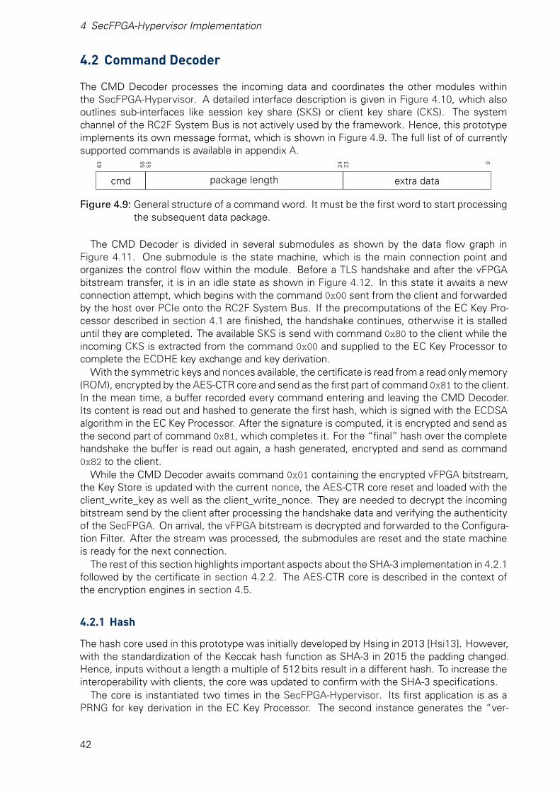
4 SecFPGA-Hypervisor Implementation
4.2 Command Decoder
The CMD Decoder processes the incoming data and coordinates the other modules withinthe SecFPGA-Hypervisor. A detailed interface description is given in Figure 4.10, which alsooutlines sub-interfaces like session key share (SKS) or client key share (CKS). The systemchannel of the RC2F System Bus is not actively used by the framework. Hence, this prototypeimplements its own message format, which is shown in Figure 4.9. The full list of of currentlysupported commands is available in appendix A.
63 56 55 24 23 0
cmd package length extra data
Figure 4.9: General structure of a command word. It must be the first word to start processingthe subsequent data package.
The CMD Decoder is divided in several submodules as shown by the data flow graph inFigure 4.11. One submodule is the state machine, which is the main connection point andorganizes the control flow within the module. Before a TLS handshake and after the vFPGAbitstream transfer, it is in an idle state as shown in Figure 4.12. In this state it awaits a newconnection attempt, which begins with the command 0x00 sent from the client and forwardedby the host over PCIe onto the RC2F System Bus. If the precomputations of the EC Key Pro-cessor described in section 4.1 are finished, the handshake continues, otherwise it is stalleduntil they are completed. The available SKS is send with command 0x80 to the client while theincoming CKS is extracted from the command 0x00 and supplied to the EC Key Processor tocomplete the ECDHE key exchange and key derivation.
With the symmetric keys and nonces available, the certificate is read from a read only memory(ROM), encrypted by the AES-CTR core and send as the first part of command 0x81 to the client.In the mean time, a buffer recorded every command entering and leaving the CMD Decoder.Its content is read out and hashed to generate the first hash, which is signed with the ECDSAalgorithm in the EC Key Processor. After the signature is computed, it is encrypted and send asthe second part of command 0x81, which completes it. For the “final” hash over the completehandshake the buffer is read out again, a hash generated, encrypted and send as command0x82 to the client.
While the CMD Decoder awaits command 0x01 containing the encrypted vFPGA bitstream,the Key Store is updated with the current nonce, the AES-CTR core reset and loaded with theclient_write_key as well as the client_write_nonce. They are needed to decrypt the incomingbitstream send by the client after processing the handshake data and verifying the authenticityof the SecFPGA. On arrival, the vFPGA bitstream is decrypted and forwarded to the Configura-tion Filter. After the stream was processed, the submodules are reset and the state machineis ready for the next connection.
The rest of this section highlights important aspects about the SHA-3 implementation in 4.2.1followed by the certificate in section 4.2.2. The AES-CTR core is described in the context ofthe encryption engines in section 4.5.
4.2.1 Hash
The hash core used in this prototype was initially developed by Hsing in 2013 [Hsi13]. However,with the standardization of the Keccak hash function as SHA-3 in 2015 the padding changed.Hence, inputs without a length a multiple of 512 bits result in a different hash. To increase theinteroperability with clients, the core was updated to confirm with the SHA-3 specifications.
The core is instantiated two times in the SecFPGA-Hypervisor. Its first application is as aPRNG for key derivation in the EC Key Processor. The second instance generates the “ver-
42
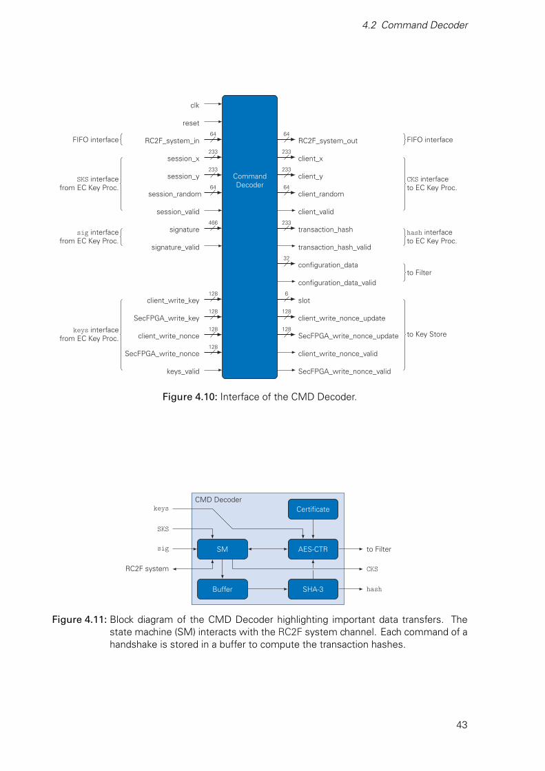
4.2 Command Decoder
clk
reset
RC2F_system_in RC2F_system_out
session_x client_x
session_y CommandDecoder
client_y
session_random client_random
session_valid client_valid
signature transaction_hash
signature_valid transaction_hash_valid
configuration_data
configuration_data_valid
client_write_key slot
SecFPGA_write_key client_write_nonce_update
client_write_nonce SecFPGA_write_nonce_update
SecFPGA_write_nonce client_write_nonce_valid
keys_valid SecFPGA_write_nonce_valid
FIFO interface
SKS interfacefrom EC Key Proc.
sig interfacefrom EC Key Proc.
keys interfacefrom EC Key Proc.
FIFO interface
CKS interfaceto EC Key Proc.
hash interfaceto EC Key Proc.
to Filter
to Key Store
64
233
233
64
466
128
128
128
128
64
233
233
64
233
32
6
128
128
Figure 4.10: Interface of the CMD Decoder.
CMD Decoder
AES-CTR
Certificate
SHA-3
SM
Buffer
keys
sig
SKS
RC2F system
to Filter
hash
CKS
Figure 4.11: Block diagram of the CMD Decoder highlighting important data transfers. Thestate machine (SM) interacts with the RC2F system channel. Each command of ahandshake is stored in a buffer to compute the transaction hashes.
43

4 SecFPGA-Hypervisor Implementation
idle
send0x80
process0x00
wait
forE
CD
HE
send0x81
wait
for“verify”
hashw
aitfor
EC
DS
A
send0x81
(sig)
wait
for“final”
hash
send0x82
wait
for0x01
process0x01
0x00received/send
sessionkey
share0x00
received
0x80sent
clientkey
shareextracted
symm
etrickeys
valid/encrypt
certificateand
sendsignature
calculated/encrypt
signatureand
send
signauresend/
starthashing
hashdone/
encryptand
sendverify
handshakehash
sent/updatenonce
0x01received/de-
cryptvFP
GA
bitstream
vFPG
Abitstream
forwarded
tofilter
hashdone/
startE
CD
SA
certificateencrypted/
starthashing
Figure4.12:S
tatem
achineof
theC
MD
Decoder.
Com
mands
aresend
andreceived
throughthe
RC
2FS
ystemB
us’ssystem
channeltoand
fromthe
client.
44
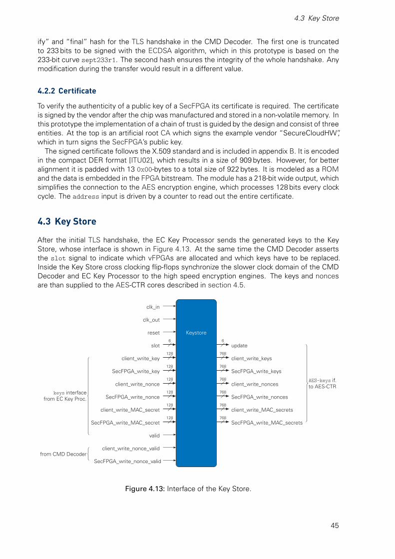
4.3 Key Store
ify” and “final” hash for the TLS handshake in the CMD Decoder. The first one is truncatedto 233 bits to be signed with the ECDSA algorithm, which in this prototype is based on the233-bit curve sept233r1. The second hash ensures the integrity of the whole handshake. Anymodification during the transfer would result in a different value.
4.2.2 Certificate
To verify the authenticity of a public key of a SecFPGA its certificate is required. The certificateis signed by the vendor after the chip was manufactured and stored in a non-volatile memory. Inthis prototype the implementation of a chain of trust is guided by the design and consist of threeentities. At the top is an artificial root CA which signs the example vendor “SecureCloudHW”,which in turn signs the SecFPGA’s public key.
The signed certificate follows the X.509 standard and is included in appendix B. It is encodedin the compact DER format [ITU02], which results in a size of 909 bytes. However, for betteralignment it is padded with 13 0x00-bytes to a total size of 922 bytes. It is modeled as a ROMand the data is embedded in the FPGA bitstream. The module has a 218-bit wide output, whichsimplifies the connection to the AES encryption engine, which processes 128 bits every clockcycle. The address input is driven by a counter to read out the entire certificate.
4.3 Key Store
After the initial TLS handshake, the EC Key Processor sends the generated keys to the KeyStore, whose interface is shown in Figure 4.13. At the same time the CMD Decoder assertsthe slot signal to indicate which vFPGAs are allocated and which keys have to be replaced.Inside the Key Store cross clocking flip-flops synchronize the slower clock domain of the CMDDecoder and EC Key Processor to the high speed encryption engines. The keys and noncesare than supplied to the AES-CTR cores described in section 4.5.
clk_in
clk_out
reset Keystore
slot update
client_write_key client_write_keys
SecFPGA_write_key SecFPGA_write_keys
client_write_nonce client_write_nonces
SecFPGA_write_nonce SecFPGA_write_nonces
client_write_MAC_secret client_write_MAC_secrets
SecFPGA_write_MAC_secret SecFPGA_write_MAC_secrets
valid
client_write_nonce_valid
SecFPGA_write_nonce_valid
keys interfacefrom EC Key Proc.
from CMD Decoder
AES-keys if.to AES-CTR
6
128
128
128
128
128
128
6
768
768
768
768
768
768
Figure 4.13: Interface of the Key Store.
45
4 SecFPGA-Hypervisor Implementation
4.4 Configuration Filter
The Configuration Filter protects the SecFPGA-Hypervisor as well as other clients’ vFPGAsfrom disallowed modifications. This is possible due to the frame based structure of a bitstream,which is a sequence of commands and data. After a synchronization pattern and some setup, a repeating series of addresses and data includes the actual configuration. On a Xilinx 7Series FPGA each frame consists of 101 words and a full bitstream of a XC7VX485T contains50 176 frames [UG470]. A vFPGA is smaller and constraint to a specific area on the chip, whichis described by a certain set of frames. The addresses of those frames are determined duringthe design phase and do not change later. They set the allowed area a client’s bitstream caninfluence.
The Configuration Filter acts as a proxy and is placed in between the CMD Decoder andthe RC2F vFPGA Bus, which is connected to the PRE of the FPGA. It receives the decryptedbitstream, scans for interrupting commands like global reset or shut down and blocks them. Italso detects the command to set the frame address, which is passed to a set of six detectors,one for each vFPGA. They use the set of predefined ranges to determine if the address is withinthe enabled area. Their results are masked by to the slot signal so that the check is only validfor the allocated vFPGAs. If there is a hit, i.e. the address is within the allowed ranges, theconfiguration is passed through to the RC2F vFPGA Bus. Otherwise this part of the bitstreamis replaced with no-operation commands.
The bitstream format is designed as a continuous stream, in other words not each frame hasto have a header specifying its address. A modified bitstream could start at a valid location andwrite through a continuous sequence outside of the allowed ranges. Thus, the Filter cannotonly scan for commands to set the frame address. Through an internal counter the end ofa 101-word frame is detected and if another one follows directly afterwards, its address iscalculated based on the start address and the current offset. The same six detectors check thecalculated address and the process repeats.
4.5 Encryption Engines
Protection of the clients’ data has the highest priority. Therefore, the strong AES algorithm,described in section 2.1.1.1, was selected in section 3.3.1.1. But instead of implementing itall over again, a publicly available core by Hsing called “Tiny AES” was used [Hsi15]. It has athroughput of 128 bit/ cycle at 300 MHz. However, it only supports one-way encryption, henceadditional logic is needed to also enable decryption. The CTR mode, introduced 1979 by Diffieand Hellman [DH79], allows both ways with a single implementation. A steadily increasingcounter value is added to a nonce, also referred to as an initialization vector (IV), and encryptedwith the provided key. The resulting bit pattern is than XORed with the plain text to get thecipher. To decrypt it, the same key, nonce and the correct counter value have to be used toregenerate the same bit pattern for another XOR operation, this time with the cipher to get theplain text.
This CTR mode was implemented on top of the existing AES core, which has 21 pipelinestages. A stage was added to execute the XOR operation and two additional stages to synchro-nize the round robin interface.Because of the core’s high throughput of 4.8 GB/ s, a single corecan handle up to six RC2F-streams at the same time. Hence, only two instances are necessaryand placed between the RC2F System Bus and the vFPGA Bus. Each clock cycle the roundrobin interface handles data for a different client connected through cross clocking FIFOs asshown in Figure 4.14.
46
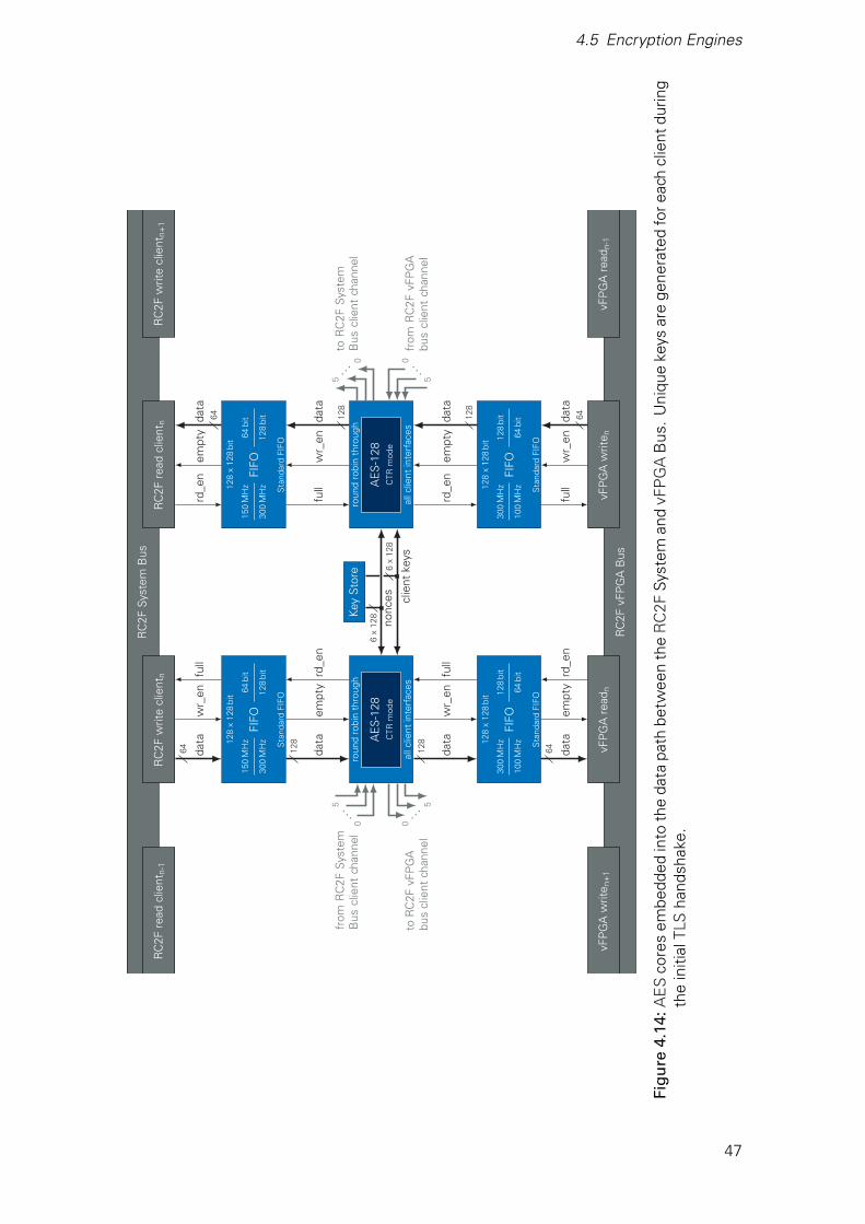
4.5 Encryption Engines
AE
S-1
28C
TRm
ode
roun
dro
bin
thro
ugh
allc
lient
inte
rfac
es
AE
S-1
28C
TRm
ode
roun
dro
bin
thro
ugh
allc
lient
inte
rfac
es
FIFO
150
MH
z
300
MH
z
64bi
t
128
bit
128
x12
8bi
t
Sta
ndar
dFI
FO
FIFO
300
MH
z
100
MH
z
128
bit
64bi
t
128
x12
8bi
t
Sta
ndar
dFI
FO
FIFO
150
MH
z
300
MH
z
64bi
t
128
bit
128
x12
8bi
t
Sta
ndar
dFI
FO
FIFO
300
MH
z
100
MH
z
128
bit
64bi
t
128
x12
8bi
t
Sta
ndar
dFI
FO
Key
Sto
re
RC
2FS
yste
mB
usR
C2F
read
clie
ntn
RC
2Fw
rite
clie
ntn
RC
2Fre
adcl
ient
n-1
RC
2Fw
rite
clie
ntn+
1
RC
2FvF
PG
AB
us
vFP
GA
read
nvF
PG
Aw
rite n
vFP
GA
read
n-1
vFP
GA
writ
e n+
1
rd_e
nem
pty
data
64
full
wr_
enda
ta
128
rd_e
nem
pty
data
128
full
wr_
enda
ta64
full
wr_
enda
ta
64
rd_e
nem
pty
data
128
full
wr_
enda
ta
128
rd_e
nem
pty
data
64
clie
ntke
ys
nonc
es6
x12
8
6x
128
0
from
RC
2FS
yste
mB
uscl
ient
chan
nel
5
...
0
5
toR
C2F
vFP
GA
bus
clie
ntch
anne
l
. ..
0fr
omR
C2F
vFP
GA
bus
clie
ntch
anne
l5
...0
toR
C2F
Sys
tem
Bus
clie
ntch
anne
l
5
. ..
Figu
re4.
14:A
ES
core
sem
bedd
edin
toth
eda
tapa
thbe
twee
nth
eR
C2F
Sys
tem
and
vFP
GA
Bus
.U
niqu
eke
ysar
ege
nera
ted
fore
ach
clie
ntdu
ring
the
initi
alTL
Sha
ndsh
ake.
47

5 Results
In this chapter the design as well as the prototypical implementation are analyzed. First, thesecurity of the SecFPGA system is evaluated against different threat levels. The deploymentdelay introduced by the TLS handshake is reported in section 5.2 followed by the extra latencythrough the AES encryption in 5.3. In the final section 5.4 the cost of security is analyzed inregards to resource utilization.
5.1 Security Evaluation
Different levels of adversaries and various attack vectors challenge the design in unique ways.In this section the security of the SecFPGA design is evaluated in regards to possible threatsdescribed in section 3.1.
Level 5: Outside of the Data Center
A threat-level-five adversary is located outside of the data center and does not have anyaccess to it, only the traffic to and from the client can be observed and altered. The SecFPGAbitstream transfer protocol is based on TLS, which is used on a daily basis around the world.Thus, the SecFPGA provides the same level of security like any other TLS connection.
Level 4: Virtualized Access to the Same Host
The host is expected to mediate the access to the PCIe bus and consequently to theSecFPGA. If an attacker breaches the virtualization layer of the VMM and is able to injectarbitrary data onto the bus, the SecFPGA-Hypervisor should not expose sensitive data. Thesame is expected if the attacker is a malicious administrator or other personal with bare metalaccess.
The design has two entry points where it receives data. The first one is the system channel,which is connected to the CMD Decoder. This module accepts only well defined commandsin order to execute a TLS handshake. Any other command or data is discarded and abortsa handshake in progress. Thus, the system channel does not allow any access to sensitivedata. The client channel is the second entry point and connected to the AES-GCM encryptionengines. In this mode the algorithm provides authenticated encryption and detects not correctlyencrypted data. But thanks to the TLS handshake, only the legitimate client is in possession ofthe required keys.
49
5 Results
Level 3: Physical Access to the Board
Before the board was manufactured, and with more effort also afterwards, compromisingcomponents, bugged memory or unwanted external interfaces could be added. Therefore, theboard itself is treated as hostile. But this is not a threat to the security of the SecFPGA, becauseclient data can only leave the SecFPGA-Hypervisor after it was AES encrypted.
Level 2: Virtualized Access to the Same Physical Chip
At threat level two, a vFPGA on the same physical chip is provisioned to an attacker. Througha careful reset process and new symmetric keys no old data is available to the attacker. TheSecFPGA design also includes a configuration filter to prevent modified bitstreams from alteringvFPGAs outside of the provisioned area. Access to the client channel cannot be blocked by anattacker, because the encryption engines offer enough throughput to serve all clients with theirmaximum bandwidth.
Level 1: Physical Access to the Chip
Since encrypted data is only as secure as the keys, they have to be protected as effectivelyas possible. Every party including the transport service, board manufacturer and data centerpersonal with physical access to the chip might tamper with it and try to extract the private key.This would allow an adversary to pass off a simulation as a trustworthy SecFPGA, clients’ sensi-tive data could be leaked. Furthermore, the symmetric keys negotiated by the TLS handshakehave to be secured from outside attackers. But these physical side-channel attacks cannot behandled solely by the design, a hardened implementation is therefore mandatory.
Level 0: Access During Design or Manufacturing
A threat-level-zero attacker can alter the design or introduce backdoors during manufacturing.At this level the SecFPGA design process itself has to be questioned and is therefore not withinthe scope of this thesis.
5.2 Deployment Delay
In a standard RC2F flow, the vFPGA bitstream is uploaded to the host by the client. Afterthat, the host hypervisor initiates the transfer to an FPGA and the RC2F hardware hypervisorstarts the reconfiguration. While stored on the host and during the transfer to the FPGA board,the vFPGA bitstreams are vulnerable to modifications and IP theft. A SecFPGA, on the otherhand, allows for a secured and confidential transfer of vFPGA configurations directly to theSecFPGA-Hypervisor. However, this requires a TLS handshake between client and SecFPGA,an obligation the RC2F does not impose.
In this section the TLS overhead is measured precisely with the Vivado Simulator [UG900]. Incontrast to measurements on an FPGA, the software tool does not impose limitations in termsof counter accuracy or record buffer depth. Instead, all computations and data exchanges canbe investigated thoroughly and with clock cycle precision. First, precomputations for the ECDSAand ECDHE are analyzed. Second, the computations based on the client key share (CKS) arediscussed.
50
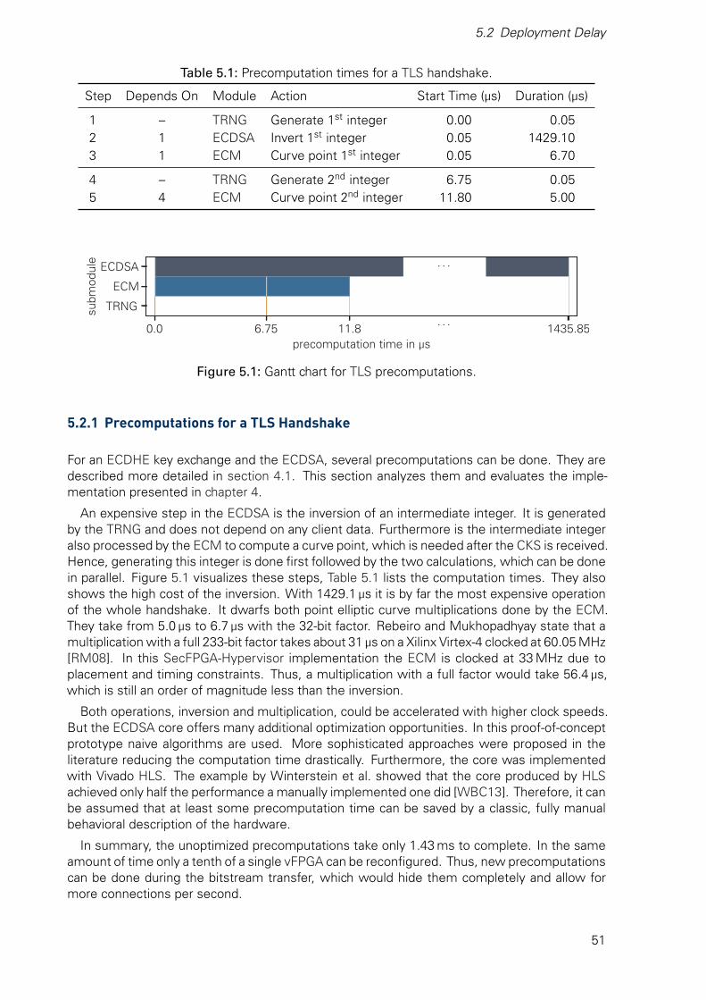
5.2 Deployment Delay
Table 5.1: Precomputation times for a TLS handshake.
Step Depends On Module Action Start Time (µs) Duration (µs)
1 – TRNG Generate 1st integer 0.00 0.052 1 ECDSA Invert 1st integer 0.05 1429.103 1 ECM Curve point 1st integer 0.05 6.70
4 – TRNG Generate 2nd integer 6.75 0.055 4 ECM Curve point 2nd integer 11.80 5.00
0.0 6.75 11.8. . .
1435.85precomputation time in µs
TRNG
ECM
ECDSA
subm
odul
e . . .
Figure 5.1: Gantt chart for TLS precomputations.
5.2.1 Precomputations for a TLS Handshake
For an ECDHE key exchange and the ECDSA, several precomputations can be done. They aredescribed more detailed in section 4.1. This section analyzes them and evaluates the imple-mentation presented in chapter 4.
An expensive step in the ECDSA is the inversion of an intermediate integer. It is generatedby the TRNG and does not depend on any client data. Furthermore is the intermediate integeralso processed by the ECM to compute a curve point, which is needed after the CKS is received.Hence, generating this integer is done first followed by the two calculations, which can be donein parallel. Figure 5.1 visualizes these steps, Table 5.1 lists the computation times. They alsoshows the high cost of the inversion. With 1429.1 µs it is by far the most expensive operationof the whole handshake. It dwarfs both point elliptic curve multiplications done by the ECM.They take from 5.0 µs to 6.7 µs with the 32-bit factor. Rebeiro and Mukhopadhyay state that amultiplication with a full 233-bit factor takes about 31 µs on a Xilinx Virtex-4 clocked at 60.05 MHz[RM08]. In this SecFPGA-Hypervisor implementation the ECM is clocked at 33 MHz due toplacement and timing constraints. Thus, a multiplication with a full factor would take 56.4 µs,which is still an order of magnitude less than the inversion.
Both operations, inversion and multiplication, could be accelerated with higher clock speeds.But the ECDSA core offers many additional optimization opportunities. In this proof-of-conceptprototype naive algorithms are used. More sophisticated approaches were proposed in theliterature reducing the computation time drastically. Furthermore, the core was implementedwith Vivado HLS. The example by Winterstein et al. showed that the core produced by HLSachieved only half the performance a manually implemented one did [WBC13]. Therefore, it canbe assumed that at least some precomputation time can be saved by a classic, fully manualbehavioral description of the hardware.
In summary, the unoptimized precomputations take only 1.43 ms to complete. In the sameamount of time only a tenth of a single vFPGA can be reconfigured. Thus, new precomputationscan be done during the bitstream transfer, which would hide them completely and allow formore connections per second.
51

5 Results
Table 5.2: Computation times for a TLS handshake after the client key share (CKS) is received.The ECC modules are located in the EC Key Processor (ECKP), the SHA-3 and AEScore in the CMD Decoder.
Step Depends On Module Action Start Time (µs) Duration (µs)
1 CKS ECDHE complete key exchange 0.00 5.002 1 ECKP key derivation 5.00 0.663 2 AES encrypt certificate 5.66 1.434 3 SHA-3 compute “verify” hash 7.09 4.015 4 ECDSA sign “verify” hash 11.10 4.406 5 AES encrypt signature 15.50 0.347 6 SHA-3 compute “final” hash 15.84 4.288 7 AES encrypt “final” hash 20.12 0.37
5.66 15.84 20.49computation time for a TLS handshake in µs
ECDHE
Key Derivation
AES
SHA-3
ECDSA
subm
odul
e
process 0x00 send 0x81 send 0x82
Figure 5.2: Gantt chart for TLS handshake after the client key share (CKS) is received. A TLShandshake cannot be parallelized significantly. Precomputations are completed be-forehand and not shown.
5.2.2 Computations during a TLS Handshake
After the precomputations are finished, the SecFPGA-Hypervisor waits for a client to request avFPGA. With the initial connection the CKS is send. This unencrypted message is encoded ascommand 0x00 and is processed right away. It takes the ECM 5 µs to calculate the commonsecret. As discussed in section 5.2.1, this depends on the ephemeral session key and cantake up to 56.4 µs if a full 233-bit factor is used. The key derivation process depends on thecommon secret as stated in Table 5.2 and shown in Figure 5.2. This prototype uses the SHA-3core described in section 4.2.1 as the PRNG to generate the symmetric keys. Its two iterationstake 0.66 µs and enable the AES core to process the certificate. An encrypted version of thecertificate cannot be stored, because with every connection new symmetric keys are derived.Thus, 1.43 µs are spent each connection to encrypt it. While it is send to the client, it is alsostored in a buffer alongside the other received and sent commands. This buffer is read outand processed by the SHA-3 core to compute the “verify” hash. After 4.01 µs the hash isfeed into the ECDSA submodule and it generate the signature in 4.4 µs. Its 466 bits have to beprocessed by the AES core, which, mainly due to the 24 pipeline stages, takes 0.34 µs. Finally,the buffer has to be read out and its content hashed again to compute the “final” hash. Withthe necessary encryption it takes 4.65 µs to send this last command 0x82.
To complete the whole handshake without precomputation, the SecFPGA-Hypervisor needs20.49 µs. Even though a TLS handshake is very linear and does not allow a great degree par-allelization, some optimization can be done. The current implementation saves every byte ofreceived or sent data in a buffer. To compute a hash, the buffer is read out. This read process
52

5.3 Extra Latency Through AES
can be started as soon as data is available. Interleaving could save about 1 - 1.5 µs for the first“verify” hash and 3.66 µs of the 4.28 µs for the “final” hash, dropping the total handshake timeto 15.33 - 15.83 µs. However, with this reduction of 25 % the possibilities for parallelism areexhausted since all other operations depend on the result of the previous one. Nevertheless,some primitives can be clocked at higher speed, e.g. the AES core with 300 MHz, the SHA-3core or the ECM. Although this reduces the impact of the interleaving described earlier, it couldsave a few µs. Especially a higher clock frequency for the ECM can directly reduce the com-putation time. The authors reported 60.04 MHz, which cuts the ECDHE time in half [RM08].Under the assumption about Vivado HLS discussed in the previous section, the performanceof the second elliptic curve module ECDSA can be doubled.
In summary, the SecFPGA-Hypervisor performs a TLS handshake in 20.49 µs. This outper-forms software implementations, e.g. an Intel Skylake CPU at 3.14 GHz takes about 1630 µsonly to verify the 233-bit ECDSA signature [CryptoPP]. But further optimizations are likely to ac-celerate handshakes between specialized hardware accelerators like two SecFPGAs. A roughestimate, based on the proposed changes outlined in this section, is a computation time of 8 µsor with full a 233-bit factor 35 µs. Both times are an order of magnitude lower than the transferand reconfiguration time of a vFPGA. Hence, the TLS overhead of the SecFPGA-Hypervisor isof no consequence compared to the RC2F.
5.3 Extra Latency Through AES
The RC2F utilizes the PCIe bus to communicate with the host. As with any form of connection ithas some latency, the time it takes the first bytes from a vFPGA to reach the client’s applicationrunning on the host machine. In a SecFPGA every byte leaving a vFPGA is encrypted and everybyte entering a vFPGA is decrypted with AES. Even though throughputs of over 32 GB/ s arereported in literature [SS15], it inevitably delays the data flow further. In this section the delayintroduced by the SecFPGA-Hypervisor is analyzed.
The implementation described in section 4.5 uses AES cores clocked at 300 MHz, whichresults in 4.8 GB/ s throughput. It employs a 21-stage pipeline to achieve such speeds. Thisis the first source of added latency introduced by the SecFPGA-Hypervisor. An extra stageexecutes the CTR mode’s XOR operation, two additional stages synchronize the round robinarbiter. They are executed at 300 MHz in contrast to a vFPGA, which operates at only 100 MHz.To synchronize the clock domains, FIFOs are embedded into the data path between the RC2FSystem Bus and the RC2F vFPGA Bus. This is the second source of latency, but the directionis important. While the RC2F vFPGA Bus is clocked at 100 MHz, the RC2F System Bus isclocked at 250 MHz allowing a faster sampling inside the FIFOs. Hence, synchronizing “fast”data to a slower clock domain takes the most amount of time. This is shown in Table 5.3, whichsummarizes the singles stages and lists the absolute delays. However, some synchronizationis also necessary in the standard RC2F design. Those times are also listed in Table 5.3 andhave to be subtracted for a fair comparison, which is shown in Table 5.4
In summary, the SecFPGA-Hypervisor adds 100 ns latency to the data path from the RC2FvFPGA to the System Bus and also 100 ns the other way around. In both cases delays theAES decryption or encryption the data by 80 ns, which accounts for 80 % of the extra latency.However, 100 ns are an order of magnitude below the 70 µs PCIe latency1 and enable strongsymmetric encryption. Even though the use of AES introduces a slight delay, it does not reducethe throughput of a vFPGA. Thus, standard RC2F data rates shown in Figure 5.3 are possible.
1Linux Kernel 4.10.0-37, VC707, RC2F loopback
53

5 Results
Table 5.3: Latencies introduced by various stages on the data path between RC2F System Busand RC2F vFPGA Bus.
Action Source (MHz) Destination (MHz) Stages Latency (ns)
AES 300 300 21 70.00CTR mode 300 300 1 3.33Round-Robin 300 300 2 6.67RC2F vFPGA Bus to AES 100 300 2 26.67a
AES to RC2F System Bus 300 250 2 23.33a
RC2F System Bus to AES 250 300 2 20.67a
AES to RC2F vFPGA Bus 300 100 2 53.33a
RC2F vFPGA to System Busb 100 250 2 30.00a
RC2F System to vFPGA Busb 250 100 2 54.00a
a worst case, [PG057] b without AES
Table 5.4: Comparison of latencies for different directions between standard RC2F and thisSecFPGA-Hypervisor implementation.
Direction RC2F (ns) SecFPGA (ns)
RC2F System to vFPGA Bus 54 154RC2F vFPGA to System Bus 30 130
10−1 100 101 102 103 104 105
Data Stream Size in MB
0
400
800
1200
1600
Thro
ughp
utin
MB
/s
writereadoverall
0
400
800
1200
1600
Figure 5.3: Throughput for a single client connected over PCIe, which is managed by RC2F.
54
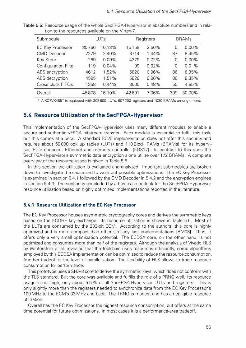
5.4 Resource Utilization of the SecFPGA-Hypervisor
Table 5.5: Resource usage of the whole SecFPGA-Hypervisor in absolute numbers and in rela-tion to the resources available on the Virtex-7.
Submodule LUTs Registers BRAMs
EC Key Processor 30 766 10.13% 15 158 2.50% 0 0.00%CMD Decoder 7279 2.40% 8714 1.44% 87 8.45%Key Store 269 0.09% 4379 0.72% 0 0.00%Configuration Filter 119 0.04% 99 0.02% 0 0.0 %AES encryption 4612 1.52% 5820 0.96% 86 8.35%AES decryption 4595 1.51% 5820 0.96% 86 8.35%Cross clock FIFOs 1358 0.44% 3000 0.48% 50 4.85%
Overall 48 878 16.10% 42 891 7.06% 309 30.00%a A XC7VX485T is equipped with 303 600 LUTs, 607 200 registers and 1030 BRAMs among others.
5.4 Resource Utilization of the SecFPGA-Hypervisor
This implementation of the SecFPGA-Hypervisor uses many different modules to enable asecure and authentic vFPGA bitstream transfer. Each module is essential to fulfill this task,but this comes at a price. A standard RC2F implementation does not offer this security andrequires about 50 000 look up tables (LUTs) and 110 Block RAMs (BRAMs) for its hypervi-sor, PCIe endpoint, Ethernet and memory controller [KGS17]. In contrast to this does theSecFPGA-Hypervisor’s symmetric data encryption alone utilize over 172 BRAMs. A completeoverview of the resource usage is given in Table 5.5.
In this section the utilization is evaluated and analyzed. Important submodules are brokendown to investigate the cause and to work out possible optimizations. The EC Key Processoris examined in section 5.4.1 followed by the CMD Decoder in 5.4.2 and the encryption enginesin section 5.4.3. The section is concluded by a best-case outlook for the SecFPGA-Hypervisorresource utilization based on highly optimized implementations reported in the literature.
5.4.1 Resource Utilization of the EC Key Processor
The EC Key Processor houses asymmetric cryptography cores and derives the symmetric keysbased on the ECDHE key exchange. Its resource utilization is shown in Table 5.6. Most ofthe LUTs are consumed by the 233-bit ECM. According to the authors, this core is highlyoptimized and is more compact than other similarly fast implementations [RM08]. Thus, itoffers only a very small optimization potential. The ECDSA core, on the other hand, is notoptimized and consumes more than half of the registers. Although the analysis of Vivado HLSby Winterstein et al. revealed that the toolchain uses resources efficiently, some algorithmsemployed by this ECDSA implementation can be optimized to reduce the resource consumption.Another tradeoff is the level of parallelization. The flexibility of HLS allows to trade resourceconsumption for performance.
This prototype uses a SHA-3 core to derive the symmetric keys, which does not conform withthe TLS standard. But the core was available and fulfills the role of a PRNG well. Its resourceusage is not high, only about 5.5 % of all SecFPGA-Hypervisor LUTs and registers. This isonly slightly more than the registers needed to synchronize data from the EC Key Processor’s100 MHz to the ECM’s 33 MHz and back. The TRNG is modest and has a negligible resourceutilization.
Overall has the EC Key Processor the highest resource consumption, but offers at the sametime potential for future optimizations. In most cases it is a performance-area tradeoff.
55
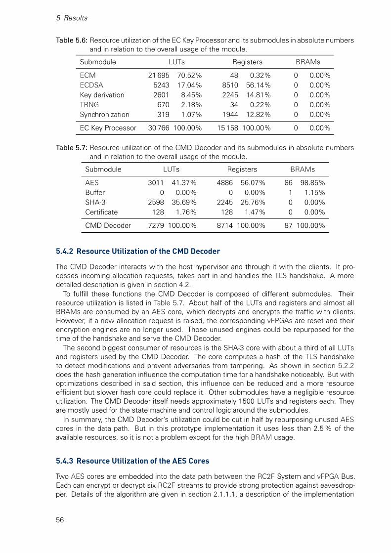
5 Results
Table 5.6: Resource utilization of the EC Key Processor and its submodules in absolute numbersand in relation to the overall usage of the module.
Submodule LUTs Registers BRAMs
ECM 21 695 70.52% 48 0.32% 0 0.00%ECDSA 5243 17.04% 8510 56.14% 0 0.00%Key derivation 2601 8.45% 2245 14.81% 0 0.00%TRNG 670 2.18% 34 0.22% 0 0.00%Synchronization 319 1.07% 1944 12.82% 0 0.00%
EC Key Processor 30 766 100.00% 15 158 100.00% 0 0.00%
Table 5.7: Resource utilization of the CMD Decoder and its submodules in absolute numbersand in relation to the overall usage of the module.
Submodule LUTs Registers BRAMs
AES 3011 41.37% 4886 56.07% 86 98.85%Buffer 0 0.00% 0 0.00% 1 1.15%SHA-3 2598 35.69% 2245 25.76% 0 0.00%Certificate 128 1.76% 128 1.47% 0 0.00%
CMD Decoder 7279 100.00% 8714 100.00% 87 100.00%
5.4.2 Resource Utilization of the CMD Decoder
The CMD Decoder interacts with the host hypervisor and through it with the clients. It pro-cesses incoming allocation requests, takes part in and handles the TLS handshake. A moredetailed description is given in section 4.2.
To fulfill these functions the CMD Decoder is composed of different submodules. Theirresource utilization is listed in Table 5.7. About half of the LUTs and registers and almost allBRAMs are consumed by an AES core, which decrypts and encrypts the traffic with clients.However, if a new allocation request is raised, the corresponding vFPGAs are reset and theirencryption engines are no longer used. Those unused engines could be repurposed for thetime of the handshake and serve the CMD Decoder.
The second biggest consumer of resources is the SHA-3 core with about a third of all LUTsand registers used by the CMD Decoder. The core computes a hash of the TLS handshaketo detect modifications and prevent adversaries from tampering. As shown in section 5.2.2does the hash generation influence the computation time for a handshake noticeably. But withoptimizations described in said section, this influence can be reduced and a more resourceefficient but slower hash core could replace it. Other submodules have a negligible resourceutilization. The CMD Decoder itself needs approximately 1500 LUTs and registers each. Theyare mostly used for the state machine and control logic around the submodules.
In summary, the CMD Decoder’s utilization could be cut in half by repurposing unused AEScores in the data path. But in this prototype implementation it uses less than 2.5 % of theavailable resources, so it is not a problem except for the high BRAM usage.
5.4.3 Resource Utilization of the AES Cores
Two AES cores are embedded into the data path between the RC2F System and vFPGA Bus.Each can encrypt or decrypt six RC2F streams to provide strong protection against eavesdrop-per. Details of the algorithm are given in section 2.1.1.1, a description of the implementation
56

5.4 Resource Utilization of the SecFPGA-Hypervisor
Table 5.8: Resource usage of an AES-128 core with an arbiter for six RC2F-streams in absolutenumbers and in relation to the overall usage of the module. In the implementationtwo of these modules are instantiated.
Submodule LUTs Registers BRAMs
AES-Core 3178 69.16% 3968 68.18% 86 100.00%Arbiter 1417 30.84% 1852 31.82% 0 0.00%
Overall 4595 100.00% 5820 100.00% 86 100.00%
and the used CTR mode in section 4.5. The resource usage is listed in Table 5.8.The most decisive feature of the AES core is its implementation of the S-Boxes. The core’s
author Hsing choose BRAMs to map them, which results in the high utilization of 8.35 % com-pared to only 1.05 % of LUTs and register relative to all available resources of the XC7VX485T.Due to the core’s speed and routing complexity, other modules cannot be mapped together withit in the same area and use the remaining resources. This imbalance leads to a poor utilizationoverall and a high area requirement of the SecFPGA-Hypervisor. Alternative implementationsrealize the S-Boxes in LUTs or as combinational logic. Zhou et al. compared all methods andreported a higher LUT utilization as a tradeoff [ZMH09]. However, only about 1100 LUTs wereneeded to replace their 41 BRAMs, which is a good compromise.
In conclusion, the AES core has a very competitive throughput/slice ratio, but uses too muchBRAMs. Thus, it increases the area requirement of the SecFPGA-Hypervisor significantly,which in turn reduces the available area for vFPGAs.
5.4.4 Estimated Utilization of an Optimized Implementation
Cryptography is not a new topic and many algorithms and even more implementations havebeen proposed in literature. With deeper understanding of the concepts, novel techniques arereported and reduce resources consumption or increase throughput. In this section the imple-mentation of the SecFPGA-Hypervisor is revised. Combining highly efficient cores proposed inliterature and optimizations described in the previous sections, a lower resource utilization canbe achieved.
The first module, which is swapped out, is the ECM. It is very fast but requires also a lotof resources. Therefore, it is replace with a more efficient core which provides higher 256-bitsecurity on curve 25519, which was specified by Bernstein [Ber06]. It uses a polynomial fieldinstead of binary, which allows for a faster processing on client side. An implementation on aVirtex-5 was realized by Sasdrich and Güneysu [SG14]. On that chip it takes 400 µs for a singlemultiplication, which is about eight times longer compared to the current implementation on afaster Virtex-7.
Another proposal targeting a Virtex-5 is a SHA-256 core by Garcia et al. [Gar14]. They aimedfor a very compact design without sacrificing the throughput, which is lower than that of theSHA-3 core by Hsing. But the hash is only needed during the handshake and its computationcan be parallelized well with other tasks. The selected SHA-256 core needs 280 clock cycles toprocess 512 bits and is clocked at 65 MHz on an older Virtex-5. A higher speed can be expectedon a more modern FPGA. The new core is not only used to compute the “verify” and “final”hash in the CMD Decoder, but also for key derivation in the EC Key Processor. This resourcesharing eliminates the need for a second instance of a hash core.
The most important change is the selection of another AES core. Hsing developed a compet-itive core with high speed and good throughput/slice ratio, but it does not offer a GCM mode,which was actually designated in the design proposed in chapter 3. Hence, Hsing’s core is re-placed with an implementation by Zhou et al. [ZMH09]. While it supports only a slightly higher
57

5 Results
Table 5.9: Estimated resource usage of an optimized SecFPGA-Hypervisor based on cores re-ported in literature. While only about 3 % slices of a XC7VX485T can be saved, theBRAM usage drops significantly and authenticated encryption is enabled.
Submodule Reference/ Slices BRAMs DSPOptimization Ref. this Ref. this Ref. this
ECM [SG14] 1029 5765 2 0 20 0Hash [Gar14] 139 715 0 0 0 0Key derivation reuse 0 714 0 0 0 0AES encryption [ZMH09] 4628 2334 0 86 0 0AES decryption [ZMH09] 4628 2052 0 86 0 0TLS encryptiona reuse 0 1226 0 86 0 0
Savings overall 2382 256 -20a De-/Encryption of handshake traffic and bitstream
throughput of 41.47 Gbit/ s it does enable the authenticated encryption AES-GCM. They alsorealized a BRAM based version, which consumes 3533 slices and 41 BRAMs. But as arguedin section 5.4.3, the high BRAM utilization reduces the overall area efficiency. Additionally anoptimization proposed in the same section is implemented. During a TLS handshake, at leastone vFPGA is reconfigured and does not transmit data. Thus, the encryption is routed throughthis free slot and saves an AES core within the CMD Decoder.
All in all is a reduction of 10 % or 2382 slices and, more importantly, 258 BRAMs possible withonly 20 additional digital signal processors (DSPs) as shown in Table 5.9. While the handshaketakes longer, it also provides more security and less load on client side. Furthermore, it betterconforms with the TLS standard, which does neither specify SHA-3 in its handshake protocol norin the supported key derivation algorithms. The authenticity of the data flow is better protectedby a strong AES-GCM.
58


6 Conclusions and Future WorkThe goal of this thesis was to develop an FPGA based system suitable for a cloud deployment.Additionally, it must allow a confidential transfer of FPGA configurations from a client to thecloud to establish a trustworthy computing space in the remote system. Initially an analysispointed out the advantages of virtualizing an FPGA into a flexible resource. Previous work, likethe RC2F, also showed the suitability of virtual FPGAs (vFPGAs) in the cloud context. But fur-ther literature review revealed their security related challenges. Furthermore, possible attacksand adversaries in a cloud environment were surveyed and together with the virtualization chal-lenges categorized into different threat levels. Based on that, two major objectives were identi-fied. First, the confidential and authentic transfer of the client’s configuration to the FPGA. Thesecond objective is the secure reconfigurability of a vFPGA.
The so called SecFPGA-Hypervisor was designed to meet these challenges. It is part of theinitial FPGA configuration, manages the vFPGAs and connects them through various high speedinterfaces like PCIe to the host and clients. To establish a secured and trustworthy connectiondirectly to the SecFPGA-Hypervisor, the TLS protocol was adapted. Because of an FPGA’slimited resources, only the most efficient algorithms and security primitives supported by TLSare used, which includes but is not limited to elliptic curve cryptography and AES encryption.Each SecFPGA is signed by the vendor after it was manufactured and thus can be authenticatedindividually by means of its standardized X.509 certificate. But the secured transfer is not theonly challenge. The complete reconfigurability of an FPGA was identified as a severe securityflaw. Thus, a filter was developed to protect the SecFPGA-Hypervisor and clients’ vFPGAs frommaliciously altered configurations.
A prototype based on the RC2F was implemented to verify important aspects of the designand to measure the overhead introduced by the new security features. The most expensivecomputations for the TLS handshake are done prior to a connection. This reduces the process-ing time on the SecFPGA to 20.49 µs, which is an order of magnitude faster than the reconfigura-tion of a single vFPGA. After the initial handshake, further data flow between client and vFPGAis AES encrypted. This delays the data, but only by an additional 100 ns, which is negligiblecompared to a 70 µs PCIe transfer time. Both latencies do not impact the deployment time orresponsiveness significantly given the vastly improved security and protect against eavesdrop-pers. On the other hand is the additional resource utilization substantial. About 15 % LUTs andBRAMs of a Virtex-7 XC7VX485T are used, but routing complexity prevents efficient mappinginto a small area.
Another conclusion from the prototype implementation confirmed the concerns raised duringthe design phase about the full reconfigurability of an FPGA. Routing resources and fixed FPGAinfrastructure inside the vFPGAs cannot be sufficiently protected without assistance of thevendor. The analysis in this thesis of FPGA virtualization suggests necessary changes to currentarchitectures to truly enable virtual yet secure FPGAs in an untrusted cloud environment:
61

6 Conclusions and Future Work
• strict separation of static FPGA infrastructure and reconfigurable space for vFPGAs
• dedicated clock distribution networks inside each vFPGA
• vFPGA bitstreams without shared address ranges
• embedded security primitives for better performance and more available chip area
• asymmetric FPGA authentication through a public key
Other improvements are not bound to a new architecture, but should be considered in futurework. The crossbar handles all traffic equally to prevent congestion caused by a single client.But it does not offer different service levels and thus it may be not as efficient as possible. If oneclient does not need a high throughput, this share could be allocated to another client whoseperformance correlates directly with the available throughput. The SecFPGA-Hypervisor can beextended to handle TLS handshakes directly over network interfaces. Current tasks of the hostlike access control and billing would either be handled within the chip or through specializedrouters. It downgrades the insecure host machine into a simple storage extension, which onlycontains securely encrypted data.
Switching from the server role into the client role does not change to TLS handshake pro-cedure considerably. Instead of generating a signature, it has to be verified. With almost allthe required primitives already in place, only this verification process has to be added to theSecFPGA to enable a direct communication between two devices. Thus, scalability within thecloud system can be improved. A client only has to connect to a single SecFPGA and set itup with a bootstrap configuration. The actual configuration is then send to the initial SecFPGA,which takes care of connecting and configuring other SecFPGAs. A secured and confidentialsubnet inside an untrusted cloud environment is established.
62


Bibliography[ABR99] Michel Abdalla et al. “DHAES: An Encryption Scheme Based on the Diffie-Hell-
man Problem.” In: IACR Cryptology ePrint Archive 1999 (1999), p. 7.
[ACM14] Karim M. Abdellatif et al. “FPGA-Based High Performance AES-GCM Using Ef-ficient Karatsuba Ofman Algorithm”. In: Reconfigurable Computing: Architec-tures, Tools, and Applications: 10th International Symposium, ARC 2014, Vilam-oura, Portugal, April 14-16, 2014. Proceedings. Ed. by Diana Goehringer et al.Cham: Springer International Publishing, 2014, pp. 13–24. DOI: 10.1007/978-3-319-05960-0_2.
[Adr15] David Adrian et al. “Imperfect Forward Secrecy: How Diffie-Hellman Fails in Prac-tice”. In: Proceedings of the 22Nd ACM SIGSAC Conference on Computer andCommunications Security. CCS ’15. Denver, Colorado, USA: ACM, 2015, pp. 5–17. ISBN: 978-1-4503-3832-5. DOI: 10.1145/2810103.2813707.
[AES] Announcing Request for Candidate Algorithm Nominations for the Advanced En-cryption Standard (AES). Department of Commerce, National Institute of Stan-dards and Technology. Sept. 12, 1997. URL: http://csrc.nist.gov/archive/aes/pre-round1/aes_9709.htm (visited on 08/01/2017).
[AES-NI] Intel Corporation. Intel Data Protection Technology with AES-NI and Secure Key.2017. URL: https://www.intel.com/content/www/us/en/architecture-and-technology/advanced-encryption-standard--aes-/data-protection-aes-general-technology.html (visited on 10/10/2017).
[AGM16] C Ashokkumar et al. “Highly Efficient Algorithms for AES Key Retrieval in CacheAccess Attacks”. In: 2016 IEEE European Symposium on Security and Privacy(EuroS P). Mar. 2016, pp. 261–275. DOI: 10.1109/EuroSP.2016.29.
[Agr07] D. Agrawal et al. “Trojan Detection using IC Fingerprinting”. In: 2007 IEEE Sym-posium on Security and Privacy (SP ’07). May 2007, pp. 296–310. DOI: 10.1109/SP.2007.36.
[AK12] George Argyros and Aggelos Kiayias. “I Forgot Your Password: Randomness At-tacks Against PHP Applications”. In: Presented as part of the 21st USENIX Secu-rity Symposium (USENIX Security 12). Bellevue, WA: USENIX, 2012, pp. 81–96.URL: https://www.usenix.org/conference/usenixsecurity12/technical-sessions/presentation/argyros.
[Aum08] Jean-Philippe Aumasson et al. “New features of Latin dances: analysis of Salsa,ChaCha, and Rumba”. In: Lecture Notes in Computer Science 5086 (2008),pp. 470–488.
XIII

Bibliography
[BCK96] Mihir Bellare et al. “Keying Hash Functions for Message Authentication”. In:Advances in Cryptology — CRYPTO ’96: 16th Annual International CryptologyConference Santa Barbara, California, USA August 18–22, 1996 Proceedings. Ed.by Neal Koblitz. Berlin, Heidelberg: Springer Berlin Heidelberg, 1996, pp. 1–15.ISBN: 978-3-540-68697-2. DOI: 10.1007/3-540-68697-5_1.
[Bel06] Mihir Bellare. “New proofs for NMAC and HMAC: Security without collision-re-sistance”. In: Annual International Cryptology Conference. Springer. 2006,pp. 602–619.
[Ber06] Daniel J Bernstein. “Curve25519: new Diffie-Hellman speed records”. In: Inter-national Workshop on Public Key Cryptography. Springer. 2006, pp. 207–228.
[Ber07] Guido Bertoni et al. “Sponge functions”. In: ECRYPT hash workshop. Vol. 2007.9. 2007.
[Ber08a] Daniel J Bernstein. “ChaCha, a variant of Salsa20”. In: Workshop Record ofSASC. Vol. 8. 2008, pp. 3–5.
[Ber08b] Daniel J. Bernstein. “The Salsa20 Family of Stream Ciphers”. In: New StreamCipher Designs: The eSTREAM Finalists. Ed. by Matthew Robshaw and OlivierBillet. Berlin, Heidelberg: Springer Berlin Heidelberg, 2008, pp. 84–97. ISBN:978-3-540-68351-3. DOI: 10.1007/978-3-540-68351-3_8.
[Bha09] S. Bhasin et al. “Security evaluation of different AES implementations againstpractical setup time violation attacks in FPGAs”. In: 2009 IEEE InternationalWorkshop on Hardware-Oriented Security and Trust. July 2009, pp. 15–21. DOI:10.1109/HST.2009.5225057.
[Bir10] Alex Biryukov et al. “Key Recovery Attacks of Practical Complexity on AES-256Variants with up to 10 Rounds”. In: Advances in Cryptology – EUROCRYPT 2010:29th Annual International Conference on the Theory and Applications of Crypto-graphic Techniques, French Riviera, May 30 – June 3, 2010. Proceedings. Ed. byHenri Gilbert. Berlin, Heidelberg: Springer Berlin Heidelberg, 2010, pp. 299–319.ISBN: 978-3-642-13190-5. DOI: 10.1007/978-3-642-13190-5_15.
[BK15] Jonathan Becktor and Christian Kiær. “TMTO Attack on the 3G Block CipherKASUMI”. Bachelor’s Thesis. Technical University of Denmark, 2015.
[BKN09] Alex Biryukov et al. “Distinguisher and Related-Key Attack on the Full AES-256”.In: Advances in Cryptology - CRYPTO 2009: 29th Annual International CryptologyConference, Santa Barbara, CA, USA, August 16-20, 2009. Proceedings. Ed. byShai Halevi. Berlin, Heidelberg: Springer Berlin Heidelberg, 2009, pp. 231–249.ISBN: 978-3-642-03356-8. DOI: 10.1007/978-3-642-03356-8_14.
[BKR11] Andrey Bogdanov et al. “Biclique cryptanalysis of the full AES”. In: Advances incryptology–ASIACRYPT 2011 (2011), pp. 344–371.
[Bos12] Joppe W Bos et al. “Solving a 112-bit prime elliptic curve discrete logarithmproblem on game consoles using sloppy reduction”. In: International Journal ofApplied Cryptography 2.3 (2012), pp. 212–228.
[Bro10] Daniel R. L. Brown. SEC 2: Recommended Elliptic Curve Domain Parameters.Tech. rep. Version 2.0. Certicom Research, Jan. 2010.
[BSI17] Kryptographische Verfahren: Empfehlungen und Schlüssellängen. Tech. rep. BSITR-02102-1. Version 2017-01. Postfach 20 03 63, 53133 Bonn, Germany: Bunde-samt für Sicherheit in der Informationstechnik, Feb. 2017.
XIV

Bibliography
[Bym14] S. Byma et al. “FPGAs in the Cloud: Booting Virtualized Hardware Acceleratorswith OpenStack”. In: 2014 IEEE 22nd Annual International Symposium on Field--Programmable Custom Computing Machines. May 2014, pp. 109–116. DOI: 10.1109/FCCM.2014.42.
[Cer10] Certicom Research. SEC 2: Recommended Elliptic Curve Domain Parameters.Tech. rep. Certicom Corp., Jan. 27, 2010.
[Che14] Fei Chen et al. “Enabling FPGAs in the cloud”. In: Proceedings of the 11th ACMConference on Computing Frontiers. ACM. 2014, p. 3.
[Cho15] David C. Chou. “Cloud computing risk and audit issues”. In: Computer Stan-dards & Interfaces 42.Supplement C (2015), pp. 137–142. ISSN: 0920-5489. DOI:https://doi.org/10.1016/j.csi.2015.06.005.
[CryptoPP] Crypto++ 5.6.5 Benchmarks. 2017. URL: https : / / www . cryptopp . com /benchmarks.html (visited on 09/27/2017).
[Dam89] Ivan Bjerre Damgård. “A design principle for hash functions”. In: Conference onthe Theory and Application of Cryptology. Springer. 1989, pp. 416–427.
[De 05] Elke De Mulder et al. “Electromagnetic analysis attack on an FPGA implementa-tion of an Elliptic curve cryptosystem”. In: Computer as a Tool, 2005. EUROCON2005. The International Conference on. Vol. 2. IEEE. 2005, pp. 1879–1882.
[DH76] Whitfield Diffie and Martin Hellman. “New directions in cryptography”. In: IEEEtransactions on Information Theory 22.6 (1976), pp. 644–654.
[DH79] W. Diffie and M. E. Hellman. “Privacy and authentication: An introduction tocryptography”. In: Proceedings of the IEEE 67.3 (Mar. 1979), pp. 397–427. ISSN:0018-9219. DOI: 10.1109/PROC.1979.11256.
[DK09] Saar Drimer and Markus G Kuhn. “A protocol for secure remote updates of FPGAconfigurations”. In: International Workshop on Applied Reconfigurable Comput-ing. Springer. 2009, pp. 50–61.
[DKS10] Orr Dunkelman et al. “A Practical-Time Related-Key Attack on the KASUMI Cryp-tosystem Used in GSM and 3G Telephony.” In: Crypto. Vol. 6223. Springer. 2010,pp. 393–410.
[DR13] Joan Daemen and Vincent Rijmen. The design of Rijndael: AES-the advancedencryption standard. Springer Science & Business Media, 2013.
[DR99] Joan Daemen and Vincent Rijmen. AES proposal: Rijndael. 1999.
[DS180] Xilinx Inc. 7 Series FPGAs Data Sheet: Overview. Aug. 1, 2017.
[DTB10] Florian Devic et al. “Secure protocol implementation for remote bitstream up-date preventing replay attacks on FPGA”. In: Field Programmable Logic and Ap-plications (FPL), 2010 International Conference on. IEEE. 2010, pp. 179–182.
[Dub14] Manish Kant Dubey et al. “Cryptanalytic Attacks and Countermeasures on RSA”.In: Proceedings of the Third International Conference on Soft Computing forProblem Solving: SocProS 2013, Volume 1. Ed. by Millie Pant et al. New Delhi:Springer India, 2014, pp. 805–819. ISBN: 978-81-322-1771-8. DOI: 10.1007/978-81-322-1771-8_70.
[Dwo15] Morris Dworkin. NIST Policy on Hash Functions. Aug. 5, 2015. URL: https :/ / csrc . nist . gov / Projects / Hash - Functions / NIST - Policy - on - Hash -Functions (visited on 09/27/2017).
XV

Bibliography
[EGE08] Esam El-Araby et al. “Virtualizing and sharing reconfigurable resources in High--Performance Reconfigurable Computing systems”. In: High-Performance Re-configurable Computing Technology and Applications, 2008. HPRCTA 2008. Sec-ond International Workshop on. IEEE. 2008, pp. 1–8.
[Eis07] Thomas Eisenbarth et al. “Reconfigurable trusted computing in hardware”. In:Proceedings of the 2007 ACM workshop on Scalable trusted computing. ACM.2007, pp. 15–20.
[EV12] K. Eguro and R. Venkatesan. “FPGAs for trusted cloud computing”. In: 22ndInternational Conference on Field Programmable Logic and Applications (FPL).Aug. 2012, pp. 63–70. DOI: 10.1109/FPL.2012.6339242.
[Fer05] Niels Ferguson. “Authentication weaknesses in GCM”. In: Comments submit-ted to NIST Modes of Operation Process (2005).
[Fer14] Diogo AB Fernandes et al. “Security issues in cloud environments: a survey”.In: International Journal of Information Security 13.2 (2014), pp. 113–170.
[FGV11] Junfeng Fan et al. “To infinity and beyond: Combined attack on ECC using pointsof low order”. In: International Workshop on Cryptographic Hardware and Em-bedded Systems. Springer. 2011, pp. 143–159.
[FIPS 180-1] FIPS 180-1. National Institute of Standards and Technology, 1995.
[FIPS 180-2] FIPS 180-2. National Institute of Standards and Technology, 2002.
[FIPS 46-2] FIPS 46-2. National Institute of Standards and Technology, 1993.
[FS03] Niels Ferguson and Bruce Schneier. Practical cryptography. Vol. 23. Wiley NewYork, 2003.
[Ful07] Scott M. Fulton. Certicom Patent Suit Against Sony Threatens to Unravel AACS.2007. URL: https://betanews.com/2007/05/30/certicom- patent- suit-against-sony-threatens-to-unravel-aacs/ (visited on 07/25/2017).
[FV12] Junfeng Fan and Ingrid Verbauwhede. “An Updated Survey on Secure ECC Im-plementations: Attacks, Countermeasures and Cost.” In: Cryptography and se-curity 6805 (2012), pp. 265–282.
[FVS15] S. A. Fahmy et al. “Virtualized FPGA Accelerators for Efficient Cloud Computing”.In: 2015 IEEE 7th International Conference on Cloud Computing Technology andScience (CloudCom). Nov. 2015, pp. 430–435. DOI: 10.1109/CloudCom.2015.60.
[Gar14] Rommel Garcia et al. “A compact FPGA-based processor for the Secure Hash Al-gorithm SHA-256”. In: Computers & Electrical Engineering 40.1 (2014), pp. 194–202.
[GC01] Kris Gaj and Pawel Chodowiec. “Fast Implementation and Fair Comparisonof the Final Candidates for Advanced Encryption Standard Using Field Pro-grammable Gate Arrays”. In: Topics in Cryptology — CT-RSA 2001: The Cryp-tographers’ Track at RSA Conference 2001 San Francisco, CA, USA, April 8–12,2001 Proceedings. Ed. by David Naccache. Berlin, Heidelberg: Springer BerlinHeidelberg, 2001, pp. 84–99. ISBN: 978-3-540-45353-6. DOI: 10.1007/3-540-45353-9_8.
[Gen09] Craig Gentry. “Fully homomorphic encryption using ideal lattices”. In: Pro-ceedings of the 41st annual ACM symposium on Symposium on theory ofcomputing-STOC\’09. ACM Press. 2009, pp. 169–169.
XVI
Bibliography
[GHR10] Kris Gaj et al. “Fair and Comprehensive Methodology for Comparing HardwarePerformance of Fourteen Round Two SHA-3 Candidates Using FPGAs”. In: Cryp-tographic Hardware and Embedded Systems, CHES 2010: 12th InternationalWorkshop, Santa Barbara, USA, August 17-20, 2010. Proceedings. Ed. by Ste-fan Mangard and François-Xavier Standaert. Berlin, Heidelberg: Springer BerlinHeidelberg, 2010, pp. 264–278. ISBN: 978-3-642-15031-9. DOI: 10.1007/978-3-642-15031-9_18.
[GMR88] Shafi Goldwasser et al. “A digital signature scheme secure against adaptive cho-sen-message attacks”. In: SIAM Journal on Computing 17.2 (1988), pp. 281–308.
[Gün89] Christoph G Günther. “An identity-based key-exchange protocol”. In: Workshopon the Theory and Application of of Cryptographic Techniques. Springer. 1989,pp. 29–37.
[Hsi13] Homer Hsing. OpenCores - SHA3 Core. Jan. 29, 2013. URL: https://opencores.org/project,sha3 (visited on 09/08/2017).
[Hsi15] Homer Hsing. OpenCores - Tiny AES. Dec. 14, 2015. URL: https://opencores.org/project,tiny_aes (visited on 09/06/2017).
[IOM12] Tetsu Iwata et al. “Breaking and Repairing GCM Security Proofs”. In: Advancesin Cryptology – CRYPTO 2012: 32nd Annual Cryptology Conference, Santa Bar-bara, CA, USA, August 19-23, 2012. Proceedings. Ed. by Reihaneh Safavi-Nainiand Ran Canetti. Berlin, Heidelberg: Springer Berlin Heidelberg, 2012, pp. 31–49.ISBN: 978-3-642-32009-5. DOI: 10.1007/978-3-642-32009-5_3.
[Ira14] Gorka Irazoqui et al. “Wait a minute! A fast, Cross-VM attack on AES”. In: Inter-national Workshop on Recent Advances in Intrusion Detection. Springer. 2014,pp. 299–319.
[Iso10] Takashi Isobe et al. “10 Gbps implementation of TLS/SSL accelerator on FPGA”.In: Quality of Service (IWQoS), 2010 18th International Workshop on. IEEE. 2010,pp. 1–6.
[ISO7498-1] Information technology – Open Systems Interconnection – Basic ReferenceModel: The Basic Model. Tech. rep. ISO/IEC 7498-1:1994. International Organi-zation for Standardization, 2000. URL: https://www.iso.org/standard/20269.html.
[ITU02] Information technology – ASN.1 encoding rules: Specification of Basic EncodingRules (BER), Canonical Encoding Rules (CER) and Distinguished Encoding Rules(DER). Tech. rep. International Telecommunication Union, 2002.
[ITU93] The Directory – Authentication Framework. Tech. rep. International Telecommu-nication Union, 1993.
[Joh16] Ray Perlner John Kelsey Shu-jen Chang. NIST Special Publication 800-185.Dec. 22, 2016. DOI: 10.6028/NIST.SP.800-185.
[Jou06] Antoine Joux. “Authentication failures in NIST version of GCM”. In: NIST Com-ment (2006), p. 3.
[KASUMI01] Universal Mobile Telecommunications System (UMTS); Specification of the3GPP confidentiality and integrity algorithms; Document 2: Kasumi algorithmspecification. Tech. rep. European Telecommunications Standards Institute,Aug. 1, 2001.
[Kay05] Phillip Kaye. “Optimized quantum implementation of elliptic curve arithmeticover binary fields”. In: Quantum Information & Computation 5.6 (2005), pp. 474–491.
XVII

Bibliography
[Kep08] Krzysztof Kepa et al. “Serecon: A secure dynamic partial reconfiguration con-troller”. In: Symposium on VLSI, 2008. ISVLSI’08. IEEE Computer Society An-nual. IEEE. 2008, pp. 292–297.
[KGK04] Paris Kitsos et al. “High-speed hardware implementations of the KASUMI blockcipher”. In: Circuits and Systems, 2004. ISCAS’04. Proceedings of the 2004 In-ternational Symposium on. Vol. 2. IEEE. 2004, pp. II–549.
[KGS17] Oliver Knodel et al. “Virtualizing Reconfigurable Hardware to Provide Scalabilityin Cloud Architectures”. In: Reconfigurable Architectures, Tools and Applications,RECATA 2017, Rom, Italien, ISBN: 978-1-61208-585-2. 2017.
[Kle10] Thorsten Kleinjung et al. “Factorization of a 768-bit RSA modulus”. In: CRYPTO2010. Vol. 6223. Springer. 2010, pp. 333–350.
[Kob87] Neal Koblitz. “Elliptic curve cryptosystems”. In: Mathematics of computation48.177 (1987), pp. 203–209.
[KR10] Ian Kuon and Jonathan Rose. Quantifying and Exploring the Gap Between FPGAsand ASICs. Springer US, 2010. ISBN: 978-1-4419-0738-7. DOI: 10.1007/978-1-4419-0739-4.
[Kra10] H. Krawczyk. Cryptographic Extraction and Key Derivation: The HKDF Scheme.Cryptology ePrint Archive, Report 2010/264. http://eprint.iacr.org/2010/264. 2010.
[Kra93] D.W. Kravitz. Digital signature algorithm. US Patent 5,231,668. July 1993. URL:https://www.google.com/patents/US5231668.
[KSZ11] Sahbuddin Abdul Kadir et al. “Simple power analysis attack against elliptic curvecryptography processor on FPGA implementation”. In: Electrical Engineeringand Informatics (ICEEI), 2011 International Conference on. IEEE. 2011, pp. 1–4.
[Lee11] Moon Sung Lee. “On the sparse subset sum problem from Gentry-Halevi’simplementation of fully homomorphic encryption.” In: IACR Cryptology ePrintArchive 2011 (2011), p. 567.
[Len93] A. K. Lenstra et al. “The number field sieve”. In: The development of the numberfield sieve. Ed. by Arjen K. Lenstra and Hendrik W. Lenstra. Berlin, Heidelberg:Springer Berlin Heidelberg, 1993, pp. 11–42. ISBN: 978-3-540-47892-8. DOI: 10.1007/BFb0091537.
[Liu11] Fang Liu et al. “NIST cloud computing reference architecture”. In: NIST specialpublication 500.2011 (2011), p. 292.
[LSP02] Chenghuai Lu et al. “Implementation of fast RSA key generation on smart cards”.In: Proceedings of the 2002 ACM symposium on Applied computing. ACM. 2002,pp. 214–220.
[Luc02] Stefan Lucks. “The Saturation Attack — A Bait for Twofish”. In: Fast SoftwareEncryption: 8th International Workshop, FSE 2001 Yokohama, Japan, April 2–4,2001 Revised Papers. Ed. by Mitsuru Matsui. Berlin, Heidelberg: Springer BerlinHeidelberg, 2002, pp. 1–15. ISBN: 978-3-540-45473-1. DOI: 10.1007/3- 540-45473-X_1.
[Men07] Nele Mentens. “Secure and efficient coprocessor design for cryptographic ap-plications on FPGAs”. PhD thesis. Katholieke Universiteit Leuven, 2007.
[Mer89] Ralph C Merkle. “A certified digital signature”. In: Conference on the Theoryand Application of Cryptology. Springer. 1989, pp. 218–238.
[MG11] Peter Mell and Timothy Grance. “The NIST definition of cloud computing”. In:(2011). DOI: 10.6028/NIST.SP.800-145.
XVIII
Bibliography
[Mic04] Harris E Michail et al. “Efficient implementation of the keyed-hash messageauthentication code (HMAC) using the SHA-1 hash function”. In: Electronics,Circuits and Systems, 2004. ICECS 2004. Proceedings of the 2004 11th IEEEInternational Conference on. IEEE. 2004, pp. 567–570.
[Mic12] Harris E. Michail et al. “On the Exploitation of a High-throughput SHA-256 FPGADesign for HMAC”. In: ACM Trans. Reconfigurable Technol. Syst. 5.1 (Mar. 2012),2:1–2:28. ISSN: 1936-7406. DOI: 10.1145/2133352.2133354.
[Mil85] Victor S Miller. “Use of elliptic curves in cryptography”. In: Conference on theTheory and Application of Cryptographic Techniques. Springer. 1985, pp. 417–426.
[MIV15] Harris E. Michail et al. “Pipelined SHA-3 Implementations on FPGA: Architec-ture and Performance Analysis”. In: Proceedings of the Second Workshopon Cryptography and Security in Computing Systems. CS2 ’15. Amsterdam,Netherlands: ACM, 2015, 13:13–13:18. ISBN: 978-1-4503-3187-6. DOI: 10.1145/2694805.2694808.
[Mon87] Peter L Montgomery. “Speeding the Pollard and elliptic curve methods of fac-torization”. In: Mathematics of computation 48.177 (1987), pp. 243–264.
[Moo14] Ciara Moore et al. “Practical homomorphic encryption: A survey”. In: Circuitsand Systems (ISCAS), 2014 IEEE International Symposium on. IEEE. 2014,pp. 2792–2795.
[Moo65] Gordon E Moore. “Cramming more components onto integrated circuits.” In:VLSI Technologies and Architectures - Electronics 38.8 (Apr. 1965).
[Moz] CA/Included Certificates. Mozilla Project. 2017. URL: https://wiki.mozilla.org/CA/Included_Certificates (visited on 08/25/2017).
[MRR08] Debdeep Mukhopadhyay et al. Elliptic Curve Crypto Processor for FPGA Plat-forms. Dec. 9, 2008. URL: http://cse.iitkgp.ac.in/~debdeep/osscrypto/eccpweb/index.html.
[MSE10] Dominik Merli et al. “Improving the quality of ring oscillator PUFs on FPGAs”. In:Proceedings of the 5th workshop on embedded systems security. ACM. 2010,p. 9.
[MV04a] David A. McGrew and John Viega. “The Security and Performance of the Galois/-Counter Mode (GCM) of Operation”. In: In INDOCRYPT, volume 3348 of LNCS.Springer, 2004, pp. 343–355.
[MV04b] David McGrew and John Viega. “The Galois/counter mode of operation (GCM)”.In: Submission to NIST Modes of Operation Process 20 (2004).
[MW15] John Mattsson and Magnus Westerlund. Authentication Key Recovery on GaloisCounter Mode (GCM). Cryptology ePrint Archive, Report 2015/477. http : / /eprint.iacr.org/2015/477. 2015. DOI: http://dx.doi.org/10.1007/978-3-319-31517-1_7.
[Nat15] National Security Agency. Suite B Cryptography. Aug. 19, 2015. URL: https :/ / web . archive . org / web / 20150831131731 / https : / / www . nsa . gov / ia /programs/suiteb_cryptography/index.shtml.
[NIST15] Elaine Barker and Allen Roginsky. Transitions: Recommendation for Transitioningthe Use of Cryptographic Algorithms and Key Lengths. Tech. rep. Revision 1.National Institute of Standards and Technology, Nov. 2015. DOI: http://dx.doi.org/10.6028/NIST.SP.800-131Ar1.
XIX
Bibliography
[OST06] Dag Arne Osvik et al. “Cache Attacks and Countermeasures: The Case of AES”.In: Topics in Cryptology – CT-RSA 2006: The Cryptographers’ Track at the RSAConference 2006, San Jose, CA, USA, February 13-17, 2005. Proceedings. Ed.by David Pointcheval. Berlin, Heidelberg: Springer Berlin Heidelberg, 2006, pp. 1–20. ISBN: 978-3-540-32648-9. DOI: 10.1007/11605805_1.
[PD11] Zdenek Paral and Srinivas Devadas. “Reliable and efficient PUF-based key gener-ation using pattern matching”. In: Hardware-Oriented Security and Trust (HOST),2011 IEEE International Symposium on. IEEE. 2011, pp. 128–133.
[PG057] Xilinx Inc. FIFO Generator v13.1. LogiCORE IP Product Guide PG057. Apr. 5,2017.
[Pol78] John M Pollard. “Monte Carlo methods for index computation (mod p)”. In: Math-ematics of computation 32.143 (1978), pp. 918–924.
[PR79] Shmuel Peleg and Azriel Rosenfeld. “Breaking Substitution Ciphers Using a Re-laxation Algorithm”. In: Commun. ACM 22.11 (Nov. 1979), pp. 598–605. ISSN:0001-0782. DOI: 10.1145/359168.359174.
[PZ03] John Proos and Christof Zalka. “Shor’s discrete logarithm quantum algorithm forelliptic curves”. In: Quantum Information & Computation 3.4 (2003), pp. 317–344.
[RA03] GVS Raju and Rehan Akbani. “Elliptic curve cryptosystem and its applications”.In: Systems, Man and Cybernetics, 2003. IEEE International Conference on.Vol. 2. IEEE. 2003, pp. 1540–1543.
[Res17] E. Rescorla. The Transport Layer Security (TLS) Protocol Version 1.3. RFC. Fre-mont, CA, USA: RFC Editor, July 3, 2017. URL: https://tools.ietf.org/html/draft-ietf-tls-tls13-21 (visited on 08/02/2017). draft.
[RFC 4880] J. Callas et al. OpenPGP Message Format. RFC 4880 (Proposed Standard). RFC.Updated by RFC 5581. Fremont, CA, USA: RFC Editor, Nov. 2007. DOI: 10.17487/RFC4880. URL: https://www.rfc-editor.org/rfc/rfc4880.txt.
[RFC 5246] T. Dierks and E. Rescorla. The Transport Layer Security (TLS) Protocol Version1.2. RFC 5246 (Proposed Standard). RFC. Updated by RFCs 5746, 5878, 6176,7465, 7507, 7568, 7627, 7685, 7905, 7919. Fremont, CA, USA: RFC Editor, Aug.2008. DOI: 10.17487/RFC5246. URL: https://www.rfc- editor.org/rfc/rfc5246.txt.
[RFC 5639] M. Lochter and J. Merkle. Elliptic Curve Cryptography (ECC) Brainpool Stan-dard Curves and Curve Generation. RFC 5639 (Informational). RFC. Fremont, CA,USA: RFC Editor, Mar. 2010. DOI: 10.17487/RFC5639. URL: https://www.rfc-editor.org/rfc/rfc5639.txt.
[RFC 6101] A. Freier et al. The Secure Sockets Layer (SSL) Protocol Version 3.0. RFC 6101(Historic). RFC. Fremont, CA, USA: RFC Editor, Aug. 2011. DOI: 10 . 17487 /RFC6101. URL: https://www.rfc-editor.org/rfc/rfc6101.txt.
[RFC 7905] A. Langley et al. ChaCha20-Poly1305 Cipher Suites for Transport Layer Security(TLS). RFC 7905 (Proposed Standard). RFC. Fremont, CA, USA: RFC Editor, June2016. DOI: 10.17487/RFC7905. URL: https://www.rfc- editor.org/rfc/rfc7905.txt.
[RG14] SC Rachana and HS Guruprasad. “Emerging Security Issues and challenges incloud computing”. In: International Journal of Engineering Science and Innova-tive Technology 3 (2 2014). ISSN: 2319-5967.
XX
Bibliography
[RM08] Chester Rebeiro and Debdeep Mukhopadhyay. “High Speed Compact EllipticCurve Cryptoprocessor for FPGA Platforms.” In: Indocrypt. Vol. 5365. Springer.2008, pp. 376–388. DOI: 10.1007/978-3-540-89754-5_29.
[RS04] Phillip Rogaway and Thomas Shrimpton. “Cryptographic Hash-Function Ba-sics: Definitions, Implications, and Separations for Preimage Resistance, Sec-ond-Preimage Resistance, and Collision Resistance”. In: Fast Software En-cryption: 11th International Workshop, FSE 2004, Delhi, India, February 5-7,2004. Revised Papers. Ed. by Bimal Roy and Willi Meier. Berlin, Heidelberg:Springer Berlin Heidelberg, 2004, pp. 371–388. ISBN: 978-3-540-25937-4. DOI:10.1007/978-3-540-25937-4_24.
[RSA78] Ronald L Rivest et al. “A method for obtaining digital signatures and public-keycryptosystems”. In: Communications of the ACM 21.2 (1978), pp. 120–126.
[RSAC91] RSA Laboratories. The RSA Factoring Challenge FAQ. Mar. 18, 1991. URL: https://www.emc.com/emc- plus/rsa- labs/historical/the- rsa- factoring-challenge-faq.htm (visited on 07/31/2017).
[Ryo14] J. Ryoo et al. “Cloud Security Auditing: Challenges and Emerging Approaches”.In: IEEE Security Privacy 12.6 (Nov. 2014), pp. 68–74. ISSN: 1540-7993. DOI:10.1109/MSP.2013.132.
[SA03] Sergei P. Skorobogatov and Ross J. Anderson. “Optical Fault Induction Attacks”.In: Cryptographic Hardware and Embedded Systems - CHES 2002: 4th Inter-national Workshop Redwood Shores, CA, USA, August 13–15, 2002 RevisedPapers. Berlin, Heidelberg: Springer Berlin Heidelberg, 2003, pp. 2–12. ISBN:978-3-540-36400-9. DOI: 10.1007/3-540-36400-5_2.
[SA11] Mostafa I. Soliman and Ghada Y. Abozaid. “FPGA implementation and perfor-mance evaluation of a high throughput crypto coprocessor”. In: Journal of Par-allel and Distributed Computing 71.8 (2011), pp. 1075–1084. ISSN: 0743-7315.DOI: https://doi.org/10.1016/j.jpdc.2011.04.006.
[Sch13] Klaus Schmeh. Kryptografie - Verfahren, Protokolle, Infrastrukturen (5. Aufl.).dpunkt.verlag, 2013, pp. I–XXVII, 1–772. ISBN: 978-3-89864-435-8.
[Sch98] Bruce Schneier et al. “Twofish: A 128-bit block cipher”. In: NIST AES Proposal15 (1998).
[SDI11] G. D. Sutter et al. “Modular Multiplication and Exponentiation Architectures forFast RSA Cryptosystem Based on Digit Serial Computation”. In: IEEE Transac-tions on Industrial Electronics 58.7 (July 2011), pp. 3101–3109. ISSN: 0278-0046.DOI: 10.1109/TIE.2010.2080653.
[SG14] Pascal Sasdrich and Tim Güneysu. “Efficient Elliptic-Curve Cryptography UsingCurve25519 on Reconfigurable Devices.” In: ARC 8405 (2014), pp. 25–36.
[SH07] Jörn-Marc Schmidt and Michael Hutter. Optical and em fault-attacks on crt-basedrsa: Concrete results. 2007.
[Sha45] Claude E. Shannon. “A Mathematical Theory of Cryptography”. Sept. 1, 1945.
[Sha71] Daniel Shanks. “Class number, a theory of factorization and genera”. In: Proc.Symp. Pure Math, 1971. Vol. 20. 1971, pp. 415–440.
[Sho99] Peter W. Shor. “Polynomial-Time Algorithms for Prime Factorization and DiscreteLogarithms on a Quantum Computer”. In: SIAM Review 41.2 (1999), pp. 303–332. ISSN: 00361445. URL: http://www.jstor.org/stable/2653075.
[Sin68] A. Sinkov. Elementary Cryptanalysis: A Mathematical Approach. MathematicalAssociation of America Textbooks. Mathematical Association of America, 1968.ISBN: 9780883856222.
XXI

Bibliography
[SK05] N. Sklavos and O. Koufopavlou. “Implementation of the SHA-2 Hash FamilyStandard Using FPGAs”. In: The Journal of Supercomputing 31.3 (Mar. 2005),pp. 227–248. ISSN: 1573-0484. DOI: 10.1007/s11227-005-0086-5.
[SS15] A. Soltani and S. Sharifian. “An ultra-high throughput and fully pipelined imple-mentation of AES algorithm on FPGA”. In: Microprocessors and Microsystems39.7 (2015), pp. 480–493. ISSN: 0141-9331. DOI: https://doi.org/10.1016/j.micpro.2015.07.005.
[Ste17] Marc Stevens et al. “The first collision for full SHA-1.” In: IACR Cryptology ePrintArchive 2017 (2017), p. 190.
[Sug13] Jarosław Sugier. “Implementing Salsa20 vs. AES and Serpent Ciphers in Popular-Grade FPGA Devices”. In: New Results in Dependability and Computer Systems:Proceedings of the 8th International Conference on Dependability and Com-plex Systems DepCoS-RELCOMEX, September 9-13, 2013, Brunów, Poland. Ed.by Wojciech Zamojski et al. Heidelberg: Springer International Publishing, 2013,pp. 431–438. ISBN: 978-3-319-00945-2. DOI: 10.1007/978-3-319-00945-2_39.
[SW12] Sergei Skorobogatov and Christopher Woods. “Breakthrough Silicon ScanningDiscovers Backdoor in Military Chip”. In: Cryptographic Hardware and Embed-ded Systems – CHES 2012: 14th International Workshop, Leuven, Belgium,September 9-12, 2012. Proceedings. Berlin, Heidelberg: Springer Berlin Heidel-berg, 2012, pp. 23–40. ISBN: 978-3-642-33027-8. DOI: 10.1007/978- 3- 642-33027-8_2.
[Tan03] Andrew S Tanenbaum et al. “Computer networks, 4-th edition”. In: ed: PrenticeHall (2003).
[Tho84] Ken Thompson. “Reflections on trusting trust”. In: Communications of the ACM27.8 (1984), pp. 761–763.
[TM14] Steve Trimberger and Jason Moore. “FPGA security: From features to capabili-ties to trusted systems”. In: Proceedings of the 51st Annual Design AutomationConference. ACM. 2014, pp. 1–4.
[TPM2] TPM Main Specification Level 2. Tech. rep. Trusted Computing Group (TCG),2011. URL: https://trustedcomputinggroup.org/tpm-main-specification.
[Tri07] Steve Trimberger. “Trusted design in FPGAs”. In: Proceedings of the 44th annualDesign Automation Conference. ACM. 2007, pp. 5–8.
[UG470] Xilinx Inc. 7 Series FPGAs Configuration. User Guide 470. 1.11. Sept. 27, 2016.
[UG900] Xilinx Inc. Logic Simulation. Vivado Design Suite User Guide 900. Version 2016.4.Nov. 30, 2016.
[UG902] Xilinx Inc. High-Level Synthesis. Vivado Design Suite User Guide 902. Ver-sion 2017.1. Apr. 5, 2017.
[UY06] M. F. Uddin and A. M. Youssef. “Cryptanalysis of Simple Substitution Ciphers Us-ing Particle Swarm Optimization”. In: 2006 IEEE International Conference on Evo-lutionary Computation. 2006, pp. 677–680. DOI: 10.1109/CEC.2006.1688376.
[Wal08] John Walker. A Pseudorandom Number Sequence Test Program. Jan. 28, 2008.URL: http://www.fourmilab.ch/random/ (visited on 08/16/2017).
[WBC13] Felix Winterstein et al. “High-level synthesis of dynamic data structures: A casestudy using Vivado HLS”. In: Field-Programmable Technology (FPT), 2013 Inter-national Conference on. IEEE. 2013, pp. 362–365.
XXII
Bibliography
[WT86] A. F. Webster and S. E. Tavares. “On the Design of S-Boxes”. In: Advances inCryptology — CRYPTO ’85 Proceedings. Ed. by Hugh C. Williams. Berlin, Heidel-berg: Springer Berlin Heidelberg, 1986, pp. 523–534. ISBN: 978-3-540-39799-1.DOI: 10.1007/3-540-39799-X_41.
[WW16] Erich Wenger and Paul Wolfger. “Harder, better, faster, stronger: elliptic curvediscrete logarithm computations on FPGAs”. In: Journal of Cryptographic Engi-neering 6.4 (2016), pp. 287–297.
[ZMH09] Gang Zhou et al. “Improving Throughput of AES-GCM with Pipelined KaratsubaMultipliers on FPGAs.” In: ARC. Springer. 2009, pp. 193–203.
[ZQ14] J. Zhang and G. Qu. “A survey on security and trust of FPGA-based systems”.In: 2014 International Conference on Field-Programmable Technology (FPT). Dec.2014, pp. 147–152. DOI: 10.1109/FPT.2014.7082768.
XXIII

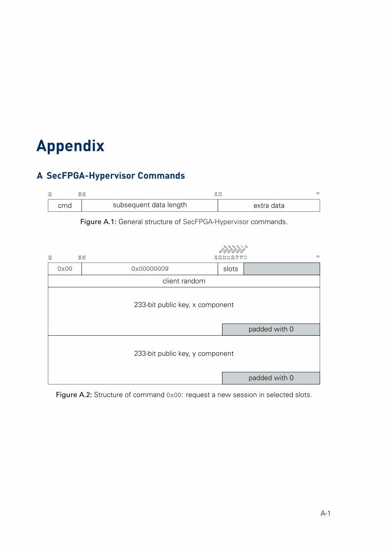
Appendix
A SecFPGA-Hypervisor Commands
63 56 55 24 23 0
cmd subsequent data length extra data
Figure A.1: General structure of SecFPGA-Hypervisor commands.
slot 5slo
t 4slo
t 3slo
t 2slo
t 1slo
t 0
63 56 55 24 23 22 21 20 19 18 17 0
0x00 0x00000009 slots
client random
233-bit public key, x component
padded with 0
233-bit public key, y component
padded with 0
Figure A.2: Structure of command 0x00: request a new session in selected slots.
A-1
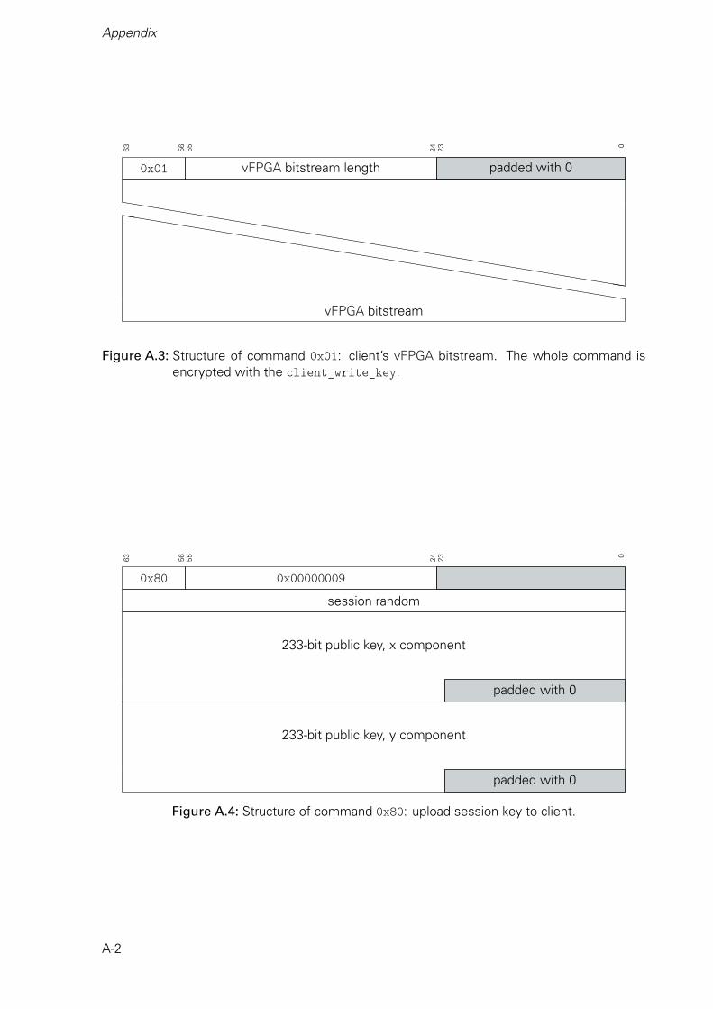
Appendix
63 56 55 24 23 0
0x01 vFPGA bitstream length padded with 0
hhhhhhhhhhhhhhhhhhhhhhhhhhhhhhhhhhhhhhhhhhhhhhhhhhhhhhhhhhhhhhhhhhhhhhhhhhhhhhhhhhhhhh
vFPGA bitstream
Figure A.3: Structure of command 0x01: client’s vFPGA bitstream. The whole command isencrypted with the client_write_key.
63 56 55 24 23 0
0x80 0x00000009
session random
233-bit public key, x component
padded with 0
233-bit public key, y component
padded with 0
Figure A.4: Structure of command 0x80: upload session key to client.
A-2
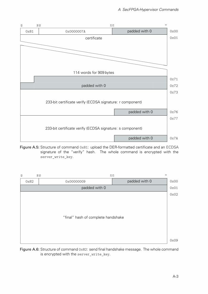
A SecFPGA-Hypervisor Commands
63 56 55 24 23 0
0x81 0x0000007A padded with 0 0x00
certificate 0x01hhhhhhhhhhhhhhhhhhhhhhhhhhhhhhhhhhhhhhhhhhh
hhhhhhhhhhhhhhhhhhhhhhhhhhhhhhhhhhhhhhhhhhh
114 words for 909 bytes
0x71
padded with 0 0x72
0x73
233-bit certificate verify (ECDSA signature: r component)
padded with 0 0x76
0x77
233-bit certificate verify (ECDSA signature: s component)
padded with 0 0x7A
Figure A.5: Structure of command 0x81: upload the DER-formatted certificate and an ECDSAsignature of the “verify” hash. The whole command is encrypted with theserver_write_key.
63 56 55 24 23 0
0x82 0x00000009 padded with 0 0x00
padded with 0 0x01
0x02
“final” hash of complete handshake
0x09
Figure A.6: Structure of command 0x82: send final handshake message. The whole commandis encrypted with the server_write_key.
A-3


B Certificate of a SecFPGA
B Certificate of a SecFPGA
Certificate:Data:
Version: 3 (0x2)Serial Number:
7f:a1:92:82:67:90:9d:69:40:a7:31:69:56:5c:6e:7c:63:4f:1d:17Signature Algorithm: sha256WithRSAEncryption
Issuer: C = DE, ST = SX, L = Dresden, O = SecureCloudHW,CN = secure-accelerator.de
ValidityNot Before: Oct 23 14:13:50 2017 GMTNot After : Oct 23 14:13:50 2019 GMT
Subject: C = DE, ST = SX, L = Dresden, O = SecureCloudHW,CN = 13A7FC.secure-accelerator.de
Subject Public Key Info:Public Key Algorithm: id-ecPublicKey
Public-Key: (233 bit)pub:
04:01:b2:3b:a2:3c:3e:8e:e5:a7:99:e7:20:2e:1d:41:ec:31:c2:98:be:1b:90:56:3c:30:6f:ff:ba:93:70:00:c2:80:e4:8d:45:77:3e:de:2c:db:70:16:54:b7:80:99:df:79:81:e2:90:0c:50:51:18:5c:9d:1c:5c
ASN1 OID: sect233r1NIST CURVE: B-233
Signature Algorithm: sha256WithRSAEncryption6f:b9:bb:93:53:07:d3:02:d9:6d:b7:a8:74:8d:24:6f:e3:a9:f6:c0:9b:57:13:1a:76:72:b1:8c:2b:8b:f6:e7:79:de:be:84:f0:39:c7:59:e2:ec:74:4e:f6:e0:c6:ac:18:5a:81:85:6f:bf:47:c1:ab:a0:a8:ff:1b:51:8a:48:c4:ba:63:d1:fc:97:76:6f:61:44:7a:24:0e:d5:c9:3a:05:57:78:7c:c5:cc:29:6d:2c:ad:9d:6b:e6:42:c4:61:2d:80:27:54:c0:86:1f:8a:5f:10:c1:97:48:14:88:c0:66:f5:2b:d7:ed:60:bf:24:06:f4:44:02:e4:52:58:50:9c:64:e0:2b:26:87:82:3a:4c:ca:05:dd:6e:75:29:25:21:2d:59:14:98:75:89:f5:64:fc:9c:66:04:31:cb:59:d8:83:1e:78:9b:6f:9a:77:35:94:aa:23:ba:02:6f:86:c5:f4:da:d6:0f:85:75:6a:57:86:a3:5b:86:5f:c6:3e:44:aa:fe:0f:36:c1:69:57:a5:26:a3:66:09:51:59:f0:03:83:92:11:0a:fa:4a:6a:2d:91:4d:9d:7d:79:24:03:19:8f:b7:e7:48:7d:80:c5:a5:e9:7b:7c:6f:68:83:14:28:fa:9b:8b:9c:5b:aa:e5:0e:cc:02:ef:7d:c2:dc:fd:f8:2a:6e:78:d3:15:a1:57:b7:20:57:1a:eb:c0:67:14:24:d6:a1:b1:31:5b:7b:a8:17:4d:da:5f:42:d8:2a:f7:96:d8:ca:b4:bb:d6:b4:37:fe:af:cb:21:ec:9d:95:87:d3:e6:fd:7c:e4:38:6b:cb:7c:df:fd:2c:97:4e:30:a1:cc:18:27:0d:eb:67:2d:05:a6:8a:1d:01:2a:29:47:7b:f0:5c:06:19:2c:b0:3b:4e:71:25:67:26:16:71:ce:41:4c:a7:a5:61:ae:55:6c:49:10:86:94:3f:50:a7:c6:ed:78:68:9d:d3:7e:78:ee:01:20:f5:9d:e4:29:0f:ca:ba:71:9e:f0:46:db:84:2e:7c:de:0f:72:1c:19:d8:68:10:64:db:ac:7c:ac:75:85:c5:7c:55:aa:42:89:60:aa:15:42:6a:b1:c8:30:07:f5:5f:c7:e2:1b:99:0b:de:bb:b1:4a:c8:fd:53:6e:f4:3f:c4:91:7c:92:15:5c:85:00:ee:d1:f8:49:60:d6:2f:96:81:ab:46:2f:a3:44:fd:21:20:fa:60:fc:34:69:81:58:b4:ea:ab:b8:85:5b:30:ee:2f:8d:58:b5:8d:65:db:65:d6:23:ca:da:fd:fb:20:36:d1:44:3e:28:81:63:b6:bc:55:1b:ea:09:de:f9:b6:13:7c
B-1
Appendix
,
B-2