· web view• commissioning tests: as part of the on-site equipment commissioning...
TRANSCRIPT
REPORT
ON
High Voltage Testing Of Transformer
Submitted in partial fulfillment of the requirement for the award of degree
Of
Bachelors of Technology
in
Electrical & Electronics Engineering
KIIT COLLEGE OF ENGINEERING
GURGAON
(Affiliated to M.D.University,Rohtak)
Submitted by:
Vivek Ambavta
Roll Number-24059
EEE 8th sem
ACKNOWLEDGEMENT
With profound respect and gratitude, I take the opportunity to convey my thanks to
complete the training here.
I do extend my heartfelt thanks for providing me this opportunity to be a part of this
esteemed organization.
I would also like to thank the training in charge of KIIT COLLEGE OF
ENGINEERING, GURGAON and all the faculty members of Electrical Engineering
Department for their effort of constant co- operation, which have been a significant factor in
the accomplishment of my report.
Vivek Ambavta
EEE-VIIIth SEM
Roll Number: 24059
KIIT COLLEGE OF ENGINEERING

Introduction
A transformer is a static device that transfers electrical energy from one circuit to another
through inductively coupled conductors—the transformer's coils. A varying current in the
first or primary winding creates a varying magnetic flux in the transformer's core and thus a
varying magnetic field through the secondary winding. This varying magnetic field induces a
varying electromotive force (EMF) or "voltage" in the secondary winding. This effect is
called mutual induction.
If a load is connected to the secondary, an electric current will flow in the secondary winding
and electrical energy will be transferred from the primary circuit through the transformer to
the load. In an ideal transformer, the induced voltage in the secondary winding (Vs) is in
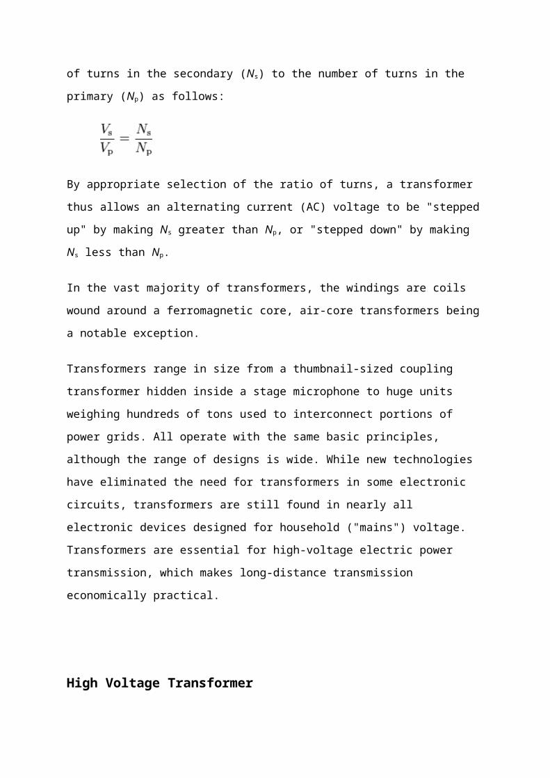
proportion to the primary voltage (Vp), and is given by the ratio of the number of turns in the
secondary (Ns) to the number of turns in the primary (Np) as follows:
By appropriate selection of the ratio of turns, a transformer thus allows an alternating current
(AC) voltage to be "stepped up" by making Ns greater than Np, or "stepped down" by making
Ns less than Np.
In the vast majority of transformers, the windings are coils wound around a ferromagnetic
core, air-core transformers being a notable exception.
Transformers range in size from a thumbnail-sized coupling transformer hidden inside a stage
microphone to huge units weighing hundreds of tons used to interconnect portions of power
grids. All operate with the same basic principles, although the range of designs is wide. While
new technologies have eliminated the need for transformers in some electronic circuits,
transformers are still found in nearly all electronic devices designed for household ("mains")
voltage. Transformers are essential for high-voltage electric power transmission, which
makes long-distance transmission economically practical.
High Voltage Transformer
High voltage transformers convert votages from one level or phase configuration to another,
usually from higher to lower. They can include features for electrical isolation, power
distribution, and control and instrumentation applications. High voltage transformers usually
depend on the principle of magnetic induction between coils to convert voltage and/or current
levels.
High voltage transformers can be configured as either a single-phase primary configuration or
a three-phase configuration. The size and cost of a transformer increases when you move
down the listing of primary windings. Single-phase primary configurations include single,
dual, quad (2+2), 5-lead, and ladder. A 5-Lead primary requires more copper than a Quad
(2+2) primary. A Ladder is the least economical primary configuration. Three-phase
transformers are connected in delta or wye configurations. A wye-delta transformer has its
primary winding connected in a wye and its secondary winding connected in a delta. A delta-
wye transformer has its primary winding connected in delta and its secondary winding
connected in a wye. Three phase configuration choices include delta - delta, delta - wye (Y),
wye (Y) – wye (Y), wye (Y) – delta, wye (Y) – single-phase, delta – single phase, and
international. Primary frequencies of incoming voltage signal to primaries available for
power transformers include 50 Hz, 60 Hz, and 400 Hz. 50 Hz is common for European
power. 60 Hz is common in North American power. 400 Hz is most widely used in aerospace
applications. The maximum primary voltage rating is another important parameter to
consider. A transformer should be provided with more than one primary winding if it is to be
used for several nominal voltages.
Other important specifications to consider when searching for high voltage transformers
include maximum secondary voltage rating, maximum secondary current rating, maximum
power rating, and output type. A transformer may provide more than one secondary voltage
value. The Rated Power of the transformer is the sum of the VA (Volts x Amps) for all of the
secondary windings. Output choices include AC or DC. For Alternating Current waveform
output, voltage the values are typically given in RMS values. Consult manufacturer for
waveform options. For direct current secondary voltage output, consult manufacturer for type
of rectification.
High voltage transformers can be constructed as either a toroidal or laminated transformer.
Toroidal transformers typically have copper wire wrapped around a cylindrical core so the
magnetic flux, which occurs within the coil, doesn't leak out, the coil efficiency is good, and
the magnetic flux has little influence on other components. Laminated transformers contain
laminated-steel cores; they are also called E-I transformers. These steel laminations are
insulated with a nonconducting material, such as varnish, and then formed into a core that
reduce electrical losses. Power transformers can be one of many types. These include
autotransformer, control transformer, current transformer, distribution transformer, general-
purpose transformer, instrument transformer, isolation transformer, potential (voltage)
transformer, power transformer, step-up transformer, and step-down transformer. Mountings
available for high voltage transformers include chassis mount, dish or disk mount, enclosure
or free standing, h frame, and PCB mount
Testing Of Transformer
As regards complex electrical equipment such as high voltage power transformers, internal
insulation is subject to defects due to several reasons associated to bad material, design,
manufacturing processesor resulting from shipment.
On-site electrical tests are for the test voltage to simulate on the transformer under testing the
equivalent stresses which may be established during service condition.
Basically, electrical tests on power transformers are grouped in type and routine tests. The
goal of a routine test is to check correct manufacture of HV insulation while the goal of a
type test is to confirm correct design of HV insulation.
In addition, the application of on-site tests may be able to be separated in:
• commissioning tests: as part of the on-site equipment commissioning procedure in order to
demonstrate that shipment and erection have not caused any new defects to HV insulation;
• on-site repair or refurbishment: as part of the repair or refurbishment procedure in order to
demonstrate that repair or refurbishment have been successfully completed and HV insulation
is free of dangerous defect; and
• diagnosis: as part of a diagnostic procedure in order to provide reference values to further
tests or to confirm results obtained from other types of test.
Up to date, on-site high voltage withstand tests including partial discharge monitoring and
measurements are the most significant tests in order to quantify HV insulation quality. The
use of a separate HV source is more informative than measurement at normal operation
voltage, as it allows investigation of the HV insulation performance with voltage.
Alternating voltages are most important for on-site tests . Other voltage shapes for simulation
of overvoltages have been used; however, they are strongly dependent on availability of on-
site testing systems.
The application of HV on-site tests has been a good practice in South America. Since 1992,
on-site HV tests have been performed in more than 110 power transformers ranging from
30MVA to 550MVA, 115kV to 765kV (AC) and 600kV (DC). Large electric power utilities
and industrial plants are the main customers to this technology.
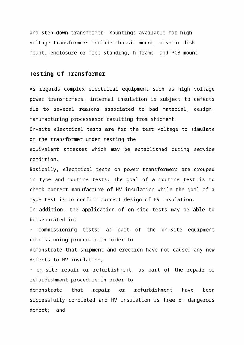
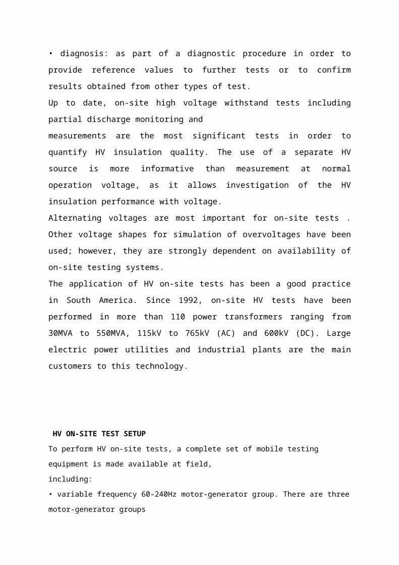
HV ON-SITE TEST SETUP
To perform HV on-site tests, a complete set of mobile testing equipment is made available at field,
including:
• variable frequency 60-240Hz motor-generator group. There are three motor-generator groups
available: 300kVA, 850kVA and 2MVA. The proper group is selected according to transformer
power and voltage;
• step-up and regulating transformers;
• reactive power compensating capacitors and reactors;
• no-load and load measuring system; and
• partial discharges measuring and monitoring system as per IEC60076-3 and IEC60270.
HV ON-SITE TESTS APPLIED FOR DIAGNOSIS
In many cases, HV on-site tests have been used for diagnostic purposes on large power transformers.
The process of this application typically starts based on previous events such as:
• detected event of in oil dissolved gas generation increase given up partial discharge as a possible
diagnosis using dissolved gas analysis methods; or
• detected mechanical event such as overacceleration during a shipment operation.
In several cases, HV induced voltage with partial discharge electrical and acoustic monitoring has
been successfully used to detect and locate partial discharge in large power transformers.
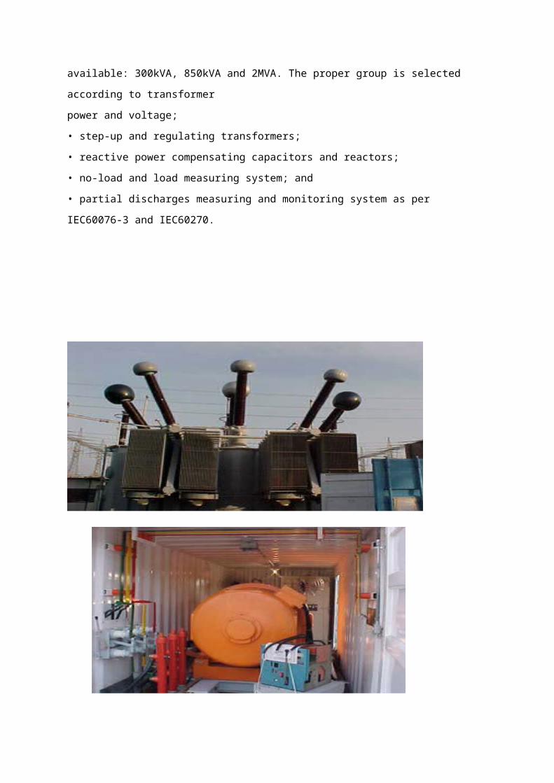
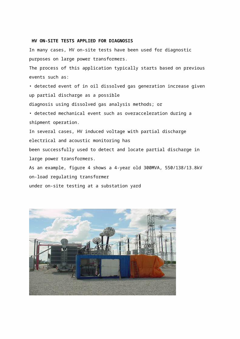
As an example, figure 4 shows a 4-year old 300MVA, 550/138/13.8kV on-load regulating transformer
under on-site testing at a substation yard
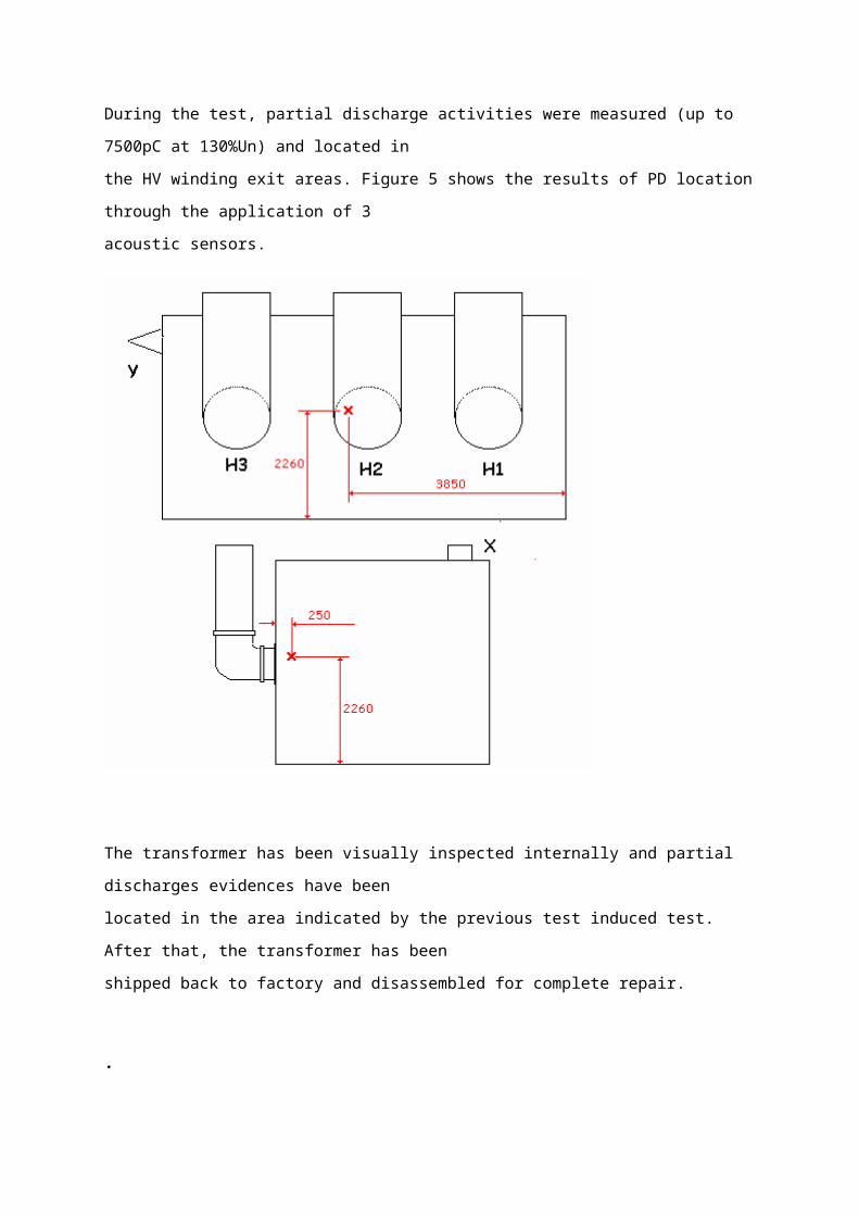
During the test, partial discharge activities were measured (up to 7500pC at 130%Un) and located in
the HV winding exit areas. Figure 5 shows the results of PD location through the application of 3
acoustic sensors.
The transformer has been visually inspected internally and partial discharges evidences have been
located in the area indicated by the previous test induced test. After that, the transformer has been
shipped back to factory and disassembled for complete repair.
.
Impulse Voltage Test Of Transformers
During the Lightning Impulse (LI) test of transformer windings with a low impedance
it is difficult to ensure a minimum time to half-value of 40 μs in accordance with IEC
60076-3 and IEC 60060-1. This is caused by the oscillating discharge
determined by the impulse voltage test generator capacitance and the transformer
impedance. In most cases using special adapted circuits can solve the problem.
1. Impulse voltage test generator with capacitive loadFor the LI testing of basic arrangements but also of different electrical components a
purely capacitive load can be assumed. The impulse voltage shape generated by an
impulse voltage test generator based on the MARX multiplier circuit can be
described by two exponential functions with different time constants. Whereas the LI
front time T1 according to IEC 60060-1 [1] is essentially determined by the
resistance of the front resistor Rs located in the impulse voltage test generator and
the load capacitance Ct, see fig. 1, the time to half-value T2 is determined by
the impulse capacitance of the impulse capacitor Ci and the resistance of the tail
resistor Rp being part of the impulse voltage test generator. According to IEC
600060-1 there are the following time parameters and tolerances for the standard LI
1.2/50: Front time T1 = 1.2 μs + 30 % Time to half-value T2 = 50 μs + 20 %
Impulse voltage test generator with inductive load
In most of the cases power transformers cannot be assumed as a purely capacitive
load for the LI testing. Usually the LI test voltage is applied to one winding terminal of
the transformer to be tested, whereas all other terminals are connected with the
earth. Hereby, not only the input capacitance of the transformer winding acts as the
load for the impulse voltage test generator but also its impedance to all other short-
circuited windings.
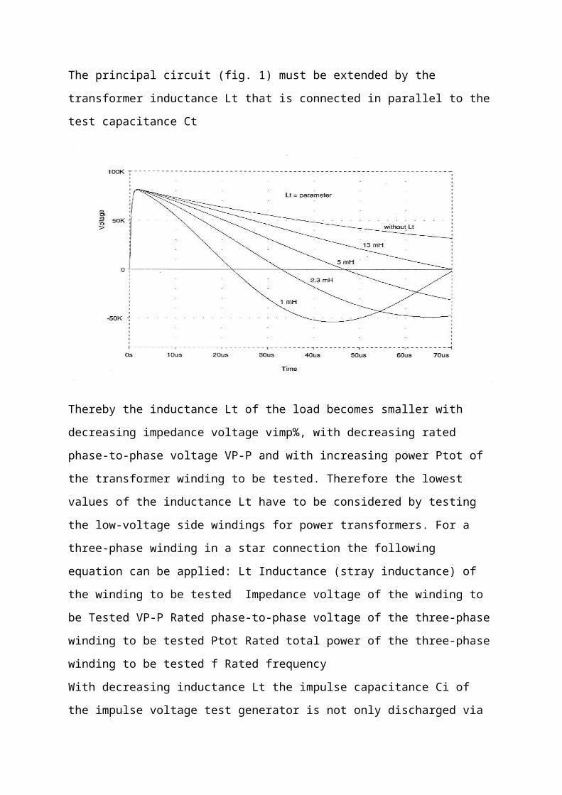
The principal circuit (fig. 1) must be extended by the transformer inductance Lt that is
connected in parallel to the test capacitance Ct
Thereby the inductance Lt of the load becomes smaller with decreasing impedance
voltage vimp%, with decreasing rated phase-to-phase voltage VP-P and with
increasing power Ptot of the transformer winding to be tested. Therefore the lowest
values of the inductance Lt have to be considered by testing the low-voltage side
windings for power transformers. For a three-phase winding in a star connection the
following equation can be applied: Lt Inductance (stray inductance) of the winding to
be tested Impedance voltage of the winding to be Tested VP-P Rated phase-to-
phase voltage of the three-phase winding to be tested Ptot Rated total power of the
three-phase winding to be tested f Rated frequency
With decreasing inductance Lt the impulse capacitance Ci of the impulse voltage test
generator is not only discharged via the tail resistor Rp, but also via the low
inductance Lt of the winding to be tested. Thereby the time to half-value T2 of the LI
is reduced and the aperiodic discharge of the impulse capacitance turns to a
damped oscillating cosine shape. This is permitted in principle acc. to IEC 60076-3
[2]. However, the lower tolerance limit for the time to half-value of T2 min
may not remain under 40 μs (= 50 μs - 20 %). At the other side the amplitude of
opposite polarity of the LI voltage dmax should not exceed 50 %.
To fulfil these both requirements the impulse voltage impulse voltage test generator
must have a minimum required impulse capacitance
Projection of an impulse voltage test generator for the LI test of power transformersThe main technical data of the transformers to be tested, like the circuitry and the
arrangement of the windings, their rated voltage, rated power, impedance voltage
and not at least the rated frequency determine essentially the total charging voltage
and the stage energy of an impulse voltage test generator for the LI test. The total
charging voltage of the impulse voltage test generator should lie for LI testing 30 %
… 60 % above the highest required LI test voltage. In many cases the value of 30 %
is sufficient for routine tests. If development tests are to be carried out, a total
charging voltage, which lies 60 % above the highest rated LI test voltage, is
recommended. If the exception “earthing via termination resistors” is not considered,
the required impulse capacitance Ci req can be calculated for each winding voltage
level acc. to equation (5). Taking into consideration the different circuitry options of
the impulse voltage test generator (parallel connection of stages, partial operation)
and the above aspects regarding the total charging voltage the stage charging
energy can be calculated in principle for each possible test case. Normally a stage
energy of 5 … 10 kJ per 100- kV-stage and a stage energy of 10 … 20 kJ per
200-kV-stage will be sufficient. Whereas the lower values apply to transformers with
lower power, the higher values apply to transformers with higher power (fig. 4).
Often, impulse voltage test generators for power transformer testing have an energy
of 15 kJ per 200-kV-stage,
Extension of the loading range of impulse voltage test generatorsOften it is required to test transformer with such a high power, for which the existing
impulse voltage test generator has not been originally meant. In such cases it is
necessary to utilise all reserves of the existing impulse voltage test generator.
Increasing the effective impulse capacitanceThe following generally known measures can be taken:
a) Running the impulse voltage test generator in partial operation, i.e. with the
minimum number of stages, being necessary to reach the required test voltage level.
b) Switching a certain number of generator stages respectively in parallel and
connect this parallel stages in series to reach the required test voltage.
Increasing the parallel resistorsIf the time to half-value remains only a few below the permitted lower limit T2 min =
40 μs, it is possible to reach a value of T2 ≥40 μs by increasing the tail resistors
Rp. Usually the tail resistors meant for switching impulse voltage can be applied. A
further increase of the resistance of the tail resistors Rp above the resistance value
for the SI generation does not have any result.
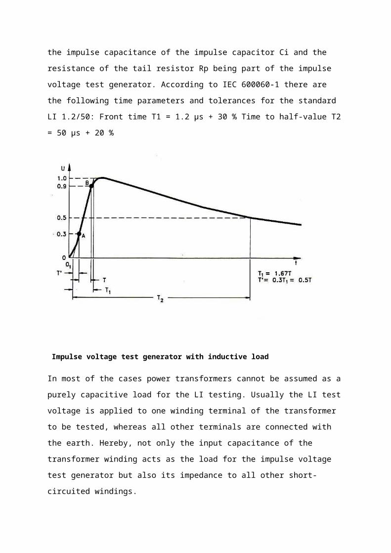
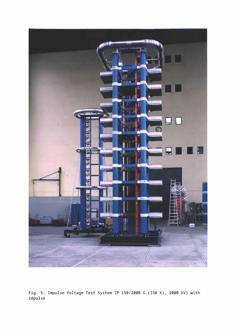
Fig. 5: Impulse Voltage Test System IP 150/2000 G (150 kJ, 2000 kV) with impulsevoltage divider and chopping multiple spark gap, with a stage energy of 15 kJ being used for theLI test of power transformers up to 245 kV
5.3. Decreasing the damping of the testcircuitAs already mentioned in chapter 2, if the circuit damping is to high, a time to half-value of T2 ≥40
μs is not reached even with a sufficient of the impulse voltage test generator (C i ≥Ci req), see fig. 3.
The front and tail resistors in the impulse voltage test generator are mostly responsible for that
damping. The damping caused by the tail resistors Rp can be considerably eliminated by their
increase, as already recommended in chapter 5.2. . For a further reduction of the damping the
resistance of the front resistor Rs has to be reduced. This would cause a shorter front time T1 of the LI.
To keep the front time T1 unchanged, the capacitance of the load has to be increased corresponding
to the reduction of the resistance of the front resistor Rs. This is easily realised by connecting
an additional capacitor in parallel to the transformer winding to be tested. Unfortunately, the effect of
this method is limited, because a reduction of the resistance of the front resistor Rs will lead to
oscillations on the front of the LI voltage soon, which may exceed the permitted limit for the overshoot
of 5 % /1/.
Application of the ”Glaninger-circuit”The disadvantage of oscillations on the voltage front after a reduction of the front resistor Rs is
completely avoided with a circuit invented by GLANINGER . Hereby the front resistor responsible
for the voltage front remains unchanged but it is bridged by an additional inductance formed by an air-
coil
The Glaninger-coil must have an inductance value ca. 100 … 200 μH, to be ineffective for the fast
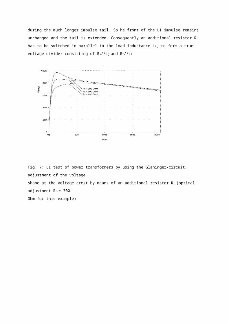
impulse front and to bridge the front resistor Rs during the much longer impulse tail. So he front of the
LI impulse remains unchanged and the tail is extended. Consequently an additional resistor R t has to
be switched in parallel to the load inductance Lt, to form a true voltage divider consisting of Rs//Lg and
Rt//Lt
Fig. 7: LI test of power transformers by using the Glaninger-circuit, adjustment of the voltage
shape at the voltage crest by means of an additional resistor Rt (optimal adjustment Rt = 300
Ohm for this example)
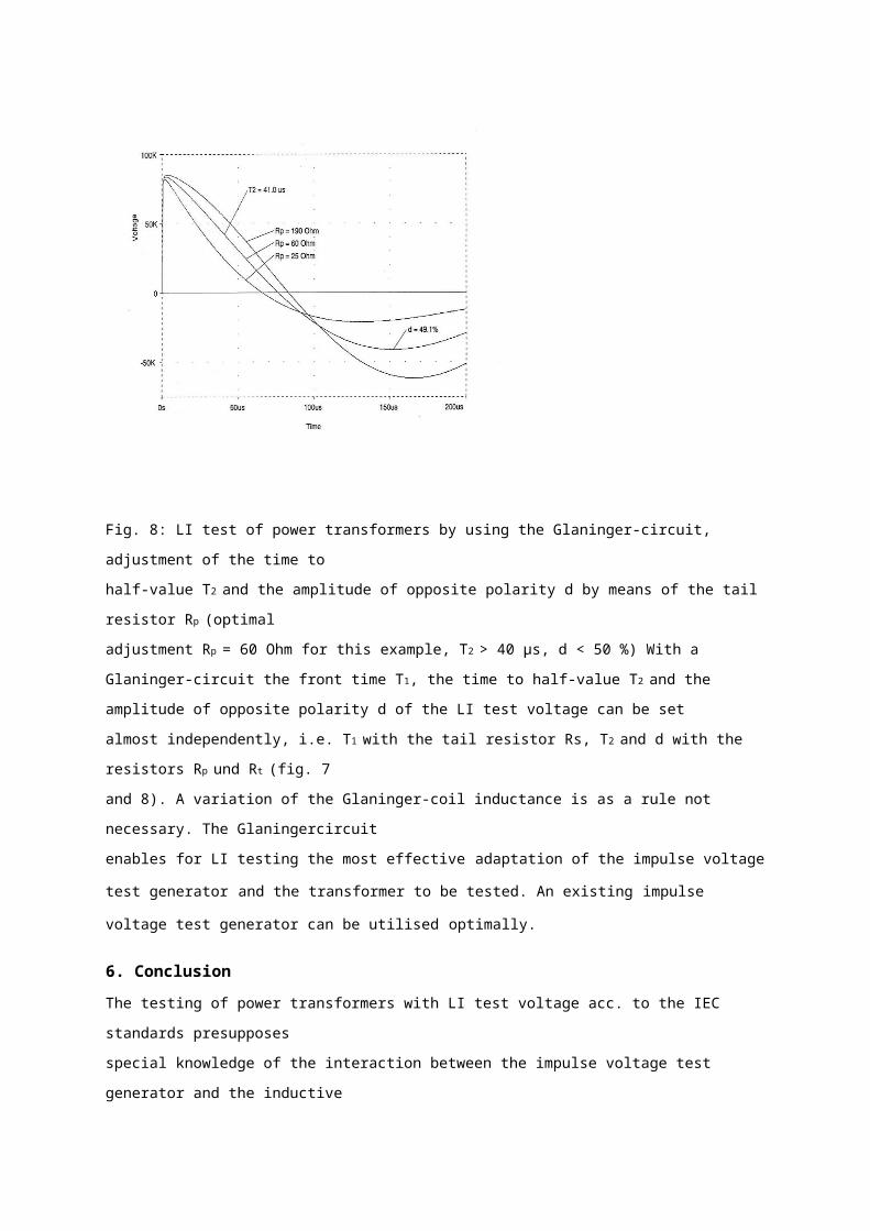
Fig. 8: LI test of power transformers by using the Glaninger-circuit, adjustment of the time to
half-value T2 and the amplitude of opposite polarity d by means of the tail resistor Rp (optimal
adjustment Rp = 60 Ohm for this example, T2 > 40 μs, d < 50 %) With a Glaninger-circuit the front time
T1, the time to half-value T2 and the amplitude of opposite polarity d of the LI test voltage can be set
almost independently, i.e. T1 with the tail resistor Rs, T2 and d with the resistors Rp und Rt (fig. 7
and 8). A variation of the Glaninger-coil inductance is as a rule not necessary. The Glaningercircuit
enables for LI testing the most effective adaptation of the impulse voltage test generator and the
transformer to be tested. An existing impulse voltage test generator can be utilised optimally.
6. ConclusionThe testing of power transformers with LI test voltage acc. to the IEC standards presupposes
special knowledge of the interaction between the impulse voltage test generator and the inductive
load. For example, there exists a close connection between the main data of the transformer to
be tested and the required impulse capacitance of the impulse voltage test generator. There are
also requirements related to the damping characteristic of the test circuit to utilise an existing
impulse voltage test generator optimally. Some basic aspects and circuitries were described
in this paper.
Oxidation of oil: Oxidation usually results in the formation of acids and sludge in the transformer liquid. It is mainly due to exposure to air and high operating temperatures.
Pressure-relief diaphragm broken: This is due to an internal fault causing excessive internal pressures or the transformer liquid level being too high or excessive internal pressure due to loading of transformer.
Discoloration of transformer liquid: Discoloration is mainly caused by carbonization of the liquid due to switching, core failure, or contaminations.
Leakage of transformer liquid: Leakage can occur through screw joints, around gaskets, welds, casting, pressure-relief device, and so on. The main causes are improper assembly of mechanical parts, improper fi lters, poor joints, improper fi nishing of surfaces, defects in the material used, or insuffi cient tightness of mechanical parts.
Moisture condensation: The main causes for moisture condensation are improper ventilation in open-type transformers and a cracked diaphragm or leaking gaskets in sealed-type transformer.
Gas-sealed transformer troubles: In gas-sealed transformers, additional problems can be the loss of gas, oxygen content above 5%, or gas regulator malfunctions. These problems are caused by gas leaks above the oil, leaky valve seats, insuffi cient gas space, and/or insuffi cient fl ushing of gas space with nitrogen.
Transformer switching equipment troubles: Many transformers are equipped with tap chargers and other switching equipment. The problems associated with these transformers may be excessive wearing of contacts, mechanism overtravel, moisture condensation in mechanism liquid, and others.
Excessive contact wear is due to loss of contact pressure from weakened springs or a contact-making voltmeter set at too narrow a bandwidth or insuffi cient time delay. Mechanism overtravel usually is due to defective or improper adjustment of controller contacts. Moisture condensation is due to improper ventilation, and carbonization is due to excessive operation and lack of fi ltering. Otherproblems such as control fuse blowing and mechanism motor stalling are due to short circuits in the control circuit, mechanical binding, or low-voltage conditions in the control circuitry
AC Hi-Pot TestThe AC hi-pot test is applied to evaluate the condition of transformer windings.This test is recommended for all voltages, especially those above 34.5 kV. For routine maintenance testing of transformers, the test voltage should not exceed 65% of factory test voltage. However, the hi-pot test for routine maintenance is generally not employed on transformers because of the possibility of damage to the winding insulation. This test is commonly used for acceptance testing or after repair testing of transformers. The AC HV test value should not exceed 75% of the factory test value. When AC hi-pot testing is to be used for routine maintenance, the transformer canbe tested at rated voltage for 3 min instead of testing at 65% of factory test voltage. The AC hi-pot test values for voltage systems up to 69 kV are shown in Table 5.9. Testing procedures and test connections are similar to the DC hi-pot tests
TTR TestThe TTR test applies voltage to one winding of a transformer and detects thevoltage being generated on another winding on the same core. In the case of a low voltage hand-crank powered TTR, 8 V AC is applied to the low-
voltage winding of the transformer under test and a reference transformer in the TTR set. The HV windings of the transformer under test and the TTR reference transformer are connected through a null detecting instrument. After polarity has been established at 8 V, when the null reading is zero, the dial readings indicate the ratio of the transformer under test.
In the case of an electronic TTR test set, a voltage (typically 80 V AC) is applied to the HV winding of the transformer under test. The voltage generated on the low-voltage winding is measured and the voltage ratio between high and low windings is calculated. Voltage ratio is proportionally equal to turns ratio. The hand-crank powered TTR, the handheld electronic TTR, and the three-phase electronic TTR are through c, respectively.The TTR test provides the following information:It determines the turns ratio and polarity o • f single- and three-phase transformers, one phase at a time.• It confi rms nameplate ratio, polarity, and vectors.• It determines the ratio and polarity (but not voltage rating) of transformers without markings. Tests include all no-load tap positions on a transformer. Tests include all load taps on load, tap changer (LTC) transformers if connected for voltage ratio control. On LTC transformers connected for phase angle control, ratio and polarity are performed in neutral positions only. If tested on load taps, readings may be taken for reference for future comparison, but will deviate from nameplate ratings. LTC taps may be confi rmed by application of low three-phase voltage and reading volts and the phase angle for each.• Identify trouble in transformer windings, such as open-circuit andshort-circuits of turn-to-turn sensitivity. The standard deviation asdefi ned by ANSI/IEEE C57.12.00-2006, Section 9.1 states that resultsshould be within 0.5% of nameplate markings, with rated voltageapplied to one winding. The TTR with accuracy of 0.1% is acceptedas a referee.