vicon iq realtime engine system option - evl · pdf filerealtime engine system option revision...
TRANSCRIPT
ViconiQ_Option_RTE.book Page i Tuesday, June 21, 2005 2:53 PM
RealTime Engine
System OptionRevision 1.0
Vicon MX and V-series Systems
Vicon iQ 2.xMotion capture production and control software

ViconiQ_Option_RTE.book Page ii Tuesday, June 21, 2005 2:53 PM
© 2005 Vicon Motion Systems Limited. All rights reserved.
For use with Vicon iQ 2.x in Vicon MX and V-series systems.
Vicon Motion Systems Limited reserves the right to make changes to information in this document without notice. Companies, names, and data used in examples are fictitious unless otherwise noted. No part of this publication may be reproduced, stored in a retrieval system, or transmitted in any form or by any means, electronic or mechanical, by photocopying or recording, or otherwise without the prior written permission of Vicon Motion Systems Limited.
Information furnished by Vicon Motion Systems Limited is believed to be accurate and reliable; however, no responsibility is assumed by Vicon Motion Systems Limited for its use; nor for any infringements of patents or other rights of third parties which may result from its use. No license is granted by implication or otherwise under any patent rights of Vicon Motion Systems Limited.
Vicon®, BodyLanguage®, DynaCal®, BodyBuilder®, and OLGA® are registered trademarks of OMG Plc. Polygon™, Workstation™, Vicon MX™, Vicon iQ™, and RealTime Engine™ are trademarks of OMG Plc.
Other product and company names herein may be the trademarks of their respective owners.
California9 Spectrum PointeLake ForestCA 92630USA
Tel: +1 (949) 472 9140Fax: +1 (949) 472 9136
Colorado7388 S. Revere Parkway, Suite 901CentennialCO 80112USA
Tel: +1 (303) 799 8686Fax: +1 (303) 799 8690
UK14 Minns Business ParkWest WayOxford OX2 0JBUK
Tel: +44 (0)1865 261800Fax: +44 (0)1865 240527
Vicon Motion Systems is an OMG Plc company
Email: [email protected]
Web: http:www.viconpeak.com
Vicon iQ RealTime Engine System Option
ViconiQ_Option_RTE.book Page iii Tuesday, June 21, 2005 2:53 PM
Contents
Preface..............................................................................................viiAudience ....................................................................... viiStructure ...................................................................... viiiConventions .....................................................................xRelated documentation .....................................................xi
Chapter 1 Introduction ................................................................ 1-1Architecture Models....................................................... 1-1Real-time Data Acquisition and Streaming........................ 1-5
Vicon File Types used in RealTime .............................. 1-6Real-time Data Acquisition and Streaming Workflow ..... 1-7
Chapter 2 Configuring the RealTime Engine................................. 2-1Configuring RealTime Engine Parameters ......................... 2-1
Opening the RealTime Engine - Edit Options Dialog Box .............................................................. 2-2Setting Parameters in the RealTime Engine - Edit Options Dialog Box ................................................... 2-3
Configuring RealTime Engine System Settings .................. 2-5
Chapter 3 Setting Up Vicon iQ ..................................................... 3-1Gathering Required Equipment and Files .......................... 3-1
Understanding Trial Types ......................................... 3-2Creating a RealTime Processing Pipeline for RoM Trials....... 3-4Preparing to Capture a RoM Trial..................................... 3-6
Chapter 4 Preparing a RealTime Subject in Vicon iQ.................... 4-1Preparing a RealTime Subject in Vicon iQ ......................... 4-2
Attaching Vicon Markers to the Subject ....................... 4-3Capturing a RoM Trial ............................................... 4-4Generating a .vsk File ..............................................4-13
Recalibrating Markers in a .vsk File .......................4-17Checking the Subject Calibration Results ....................4-18
Checking Marker Covariances ..............................4-19Checking Autolabeling ........................................4-21
Vicon iQ RealTime Engine System Option iii

Contents
ViconiQ_Option_RTE.book Page iv Tuesday, June 21, 2005 2:53 PM
Checking Kinematic Fitting ..................................4-22Checking RealTime Feedback ...............................4-25
Chapter 5 Streaming RealTime Data in Vicon iQ .......................... 5-1Preparing Vicon iQ to Receive RealTime Data .................... 5-1Managing Data Streaming with the RealTime Engine Control ........................................................................ 5-5
Displaying the RealTime Engine Control ...................... 5-5Connecting the RealTime Engine ................................ 5-6Pausing the RealTime Engine ..................................... 5-6Resetting the RealTime Engine ................................... 5-7Disconnecting the RealTime Engine ............................ 5-7
Visualizing RealTime Data in Vicon iQ .............................. 5-7
Appendix A RealTime Engine Parameters.......................................A-1Circle Fitting Parameters................................................ A-2Kinematic Fitting and Filtering Parameters........................ A-7Offline Data Streaming Parameters ................................ A-11Reconstruction Parameters............................................ A-12Trajectory Fitting Parameters ........................................ A-16Trajectory Labeling Parameters...................................... A-21
Appendix B Vicon Skeleton Template (.vst) Files ...........................B-1VST File Format ............................................................ B-2VST File Structure......................................................... B-2
XML Header ............................................................ B-3VST File Attribute Syntax .......................................... B-3
Parameters Section ....................................................... B-4Skeleton Section........................................................... B-5MarkerSet Section......................................................... B-9
Markers .................................................................B-10Sticks ....................................................................B-11
Appendix C Marker Placement in Vicon iQ......................................C-1Placement of Markers in Sample .vst File.......................... C-1
Front View .............................................................. C-2Back View ............................................................... C-3Side View ............................................................... C-4
iv Vicon iQ RealTime Engine System Option
Contents
ViconiQ_Option_RTE.book Page v Tuesday, June 21, 2005 2:53 PM
Appendix D Troubleshooting ..........................................................D-1Performance Speed ....................................................... D-1Accessing RealTime Engine on a Remote PC ..................... D-3
Appendix E Support Resources ...................................................... E-1Technical Support ......................................................... E-1
Telephone ............................................................... E-1Email ..................................................................... E-1World Wide Web ...................................................... E-1
Useful References ......................................................... E-2Vicon Online Support (VOS) ........................................... E-2
Logging in to VOS .................................................... E-3Locating Topics in VOS ............................................. E-3Submitting Questions to VOS ..................................... E-5
VOS Topics on RealTime Engine Issues ............................ E-6General RealTime Engine Issues ................................ E-6Software Downloads ................................................. E-6
Appendix F Documentation Feedback ............................................ F-1
Index .......................................................................................Index-1
Vicon iQ RealTime Engine System Option v

Contents
ViconiQ_Option_RTE.book Page vi Tuesday, June 21, 2005 2:53 PM
vi Vicon iQ RealTime Engine System Option
ViconiQ_Option_RTE.book Page vii Tuesday, June 21, 2005 2:53 PM
Preface
This book provides detailed information on the Vicon RealTime Engine, which is accessible from the Vicon iQ motion capture and analysis software and whose output can be viewed and incorporated in Vicon iQ or 3rd-party visualization software. It describes the features and functionality of the RealTime Engine and provides instructions on its operation in Vicon iQ. For further information on the general features and operation of Vicon iQ, see the other documentation supplied with it.
The information in this book applies both to Vicon MX and to Vicon V-series systems that support the RealTime Engine through the following DataStations: Vicon 460 (V460), Vicon 6 (V6), Vicon 612 (V612), Vicon 624 (V624), and Vicon 8i (V8i). In Vicon MX systems, the RealTime Engine is automatically incorporated in Vicon iQ; in Vicon V-series systems, it is a separately installable system option.
ImportantThis book assumes that your Vicon system—including the RealTime Engine software, the Vicon iQ motion capture and processing application, and any 3rd-party modeling and visualization applications—has already been set up and calibrated. RealTime Engine software is licensed using a HASP dongle. The licensing drivers must have been installed on the host PC, and the dongle must be plugged into an appropriate port (parallel or USB) on the PC while you are running the application software. For full details on preparing your Vicon MX system for use, see the Vicon MX System Setup document. For setup details for Vicon V-series systems, see "Preparation" in The Vicon Manual.
Audience
This book is intended for those who will be using the RealTime Engine to acquire, reconstruct, label, and optionally kinematically fit motion data in real time. It also is for those who will be viewing or incorporating that real-time data in visualization software.
Vicon iQ RealTime Engine System Option vii

Preface
ViconiQ_Option_RTE.book Page viii Tuesday, June 21, 2005 2:53 PM
The RealTime Engine is typically used for the following types of applications:
• Engineering, such as visualization simulation, virtual prototyping, and virtual reality.
• Entertainment, such as computer game character animation, full motion video (FMV)/cut-scenes, advertising spots, and on-set character previews.
• Life Sciences, such as sports performance, gait analysis, neuroscience, physical therapy, and object tracking in medical environments.
This book assumes that you are familiar with Microsoft Windows operating systems. It also assumes that you are familiar with the standard offline data capture performed by Vicon iQ. If you are not, please see The Vicon Manual for details on data capture and the Vicon iQ System Reference for details on the features and functionality of that Vicon application software.
This book does not assume any previous experience with the RealTime Engine. If you have used the RealTime Engine software in Vicon V-series systems, you will notice some differences in terminology and functions in this release. All RealTime Engine features, functionality, and operation are described fully in this book.
Structure
This section describes how the information in this book is organized.
The first chapter provides an overview of the RealTime Engine:
Chapter 1 Introduction describes the role of the RealTime Engine in Vicon MX and V-series systems application software and its location in the system architecture.
The following chapters describes the main steps of the real-time data acquisition and streaming workflow in Vicon iQ:
Chapter 2 Configuring the RealTime Engine explains how to configure the RealTime Engine in Vicon iQ.
Chapter 3 Setting Up Vicon iQ explains how to set up Vicon iQ to prepare RealTime subjects.
viii Vicon iQ RealTime Engine System Option

Preface
ViconiQ_Option_RTE.book Page ix Tuesday, June 21, 2005 2:53 PM
Chapter 4 Preparing a RealTime Subject in Vicon iQ explains how to prepare a Vicon Skeleton (.vsk) file for an individual whose movements are to be acquired, visualized, and analyzed in real time from Vicon iQ.
Chapter 5 Streaming RealTime Data in Vicon iQ describes the process for streaming RealTime Engine data and then visualizing and analyzing it in Vicon iQ.
Each of the appendices provide additional information that can help you make the most of using the RealTime Engine:
Appendix A RealTime Engine Parameters describes the settings and parameters used to control the operation of the RealTime Engine.
Appendix B Vicon Skeleton Template (.vst) Files describes the format, structure, and syntax of a Vicon Skeleton Template (.vst) file, which can be used to create subject-specific Vicon Skeleton (.vsk) files.
Appendix C Marker Placement in Vicon iQ describes the markers required to generate a subject-specific .vsk file and provides instructions on where to place them on subjects to correspond with a specified .vst file in Vicon iQ.
Appendix D Troubleshooting provides tips on resolving possible problems you might encounter when using the RealTime Engine in Vicon iQ.
Appendix E Support Resources describes the support resources available to Vicon system users.
Appendix F Documentation Feedback describes how to supply feedback on Vicon MX and V-series systems documentation.
Vicon iQ RealTime Engine System Option ix

Preface
ViconiQ_Option_RTE.book Page x Tuesday, June 21, 2005 2:53 PM
Conventions
This table illustrates the typographical conventions used in this book.
Item Description
This type Menus, commands, buttons, and options displayed in the GUI. Terms in a definition list or emphasis for important introductory words in a paragraph.
This type Text displayed by the system or extracts of program code.
This type Path names, file names, and extensions. Commands or text you are to enter in files or dialog boxes.
This type Cross-reference to related information in another section or document.
This type A URL for a site on the World Wide Web.
Important A note giving information that emphasizes or supplements important points in the text or information that may apply only in special cases.
Caution A caution alerting you to actions that could result in the loss of data.
Warning A warning advising you of actions that could result in physical harm to yourself or damage to the hardware.
x Vicon iQ RealTime Engine System Option
Preface
ViconiQ_Option_RTE.book Page xi Tuesday, June 21, 2005 2:53 PM
Related documentation
This Vicon iQ RealTime Engine System Option book is designed to be used in conjunction with the additional documentation providing information related to this release of Vicon iQ shown in the following table.
Document Description
Release Documents
Release Documents provide details on the current software release, including system requirements, new features and enhancements, issues addressed, and known problems as well as product feature and functionality changes from previous releases.
To access them, from the Windows Start menu, point to Programs, then Vicon, then Documentation, then Release Documents, and select the desired release document.
System Setup The System Setup document provides installation, startup, and initial configuration details to enable you to quickly get started using the system hardware and software.
Books Product books are installed in PDF format (requires Adobe Acrobat version 5.0 or later). To access them, from the Windows Start menu, point to Programs, then Vicon, then Documentation, then Books, then the type of book, and select the desired book.
The following types of books make up the Vicon product documentation set:
System Reference
System Reference books describe the features and functionality of a component of Vicon MX and V-series systems.
System Tutorial
System Tutorial books provide step-by-step instructions on the intended way of using Vicon application software.
Vicon iQ RealTime Engine System Option xi
Preface
ViconiQ_Option_RTE.book Page xii Tuesday, June 21, 2005 2:53 PM
System Option
System Option books describe the general features and operation of a system option or plug-in that can be used with the Vicon application software.
Foundation Guide
Foundation Guide books, such as The Vicon Manual, describe the general features and operation of the hardware and application software in Vicon V-series systems (V460, V6, V612, V624, and V8i).
Those books may be supplemented by the System Reference, System Tutorial, and System Option books, which describe more recent features and functionality.
Vicon Online Support (VOS)
VOS (at http://support.vicon.com) is a Web-accessible knowledge base that enables customers to view previously answered product queries, submit new questions, and download updates to Vicon software and documentation.
Document Description
xii Vicon iQ RealTime Engine System Option

ViconiQ_Option_RTE.book Page 1 Tuesday, June 21, 2005 2:53 PM
11In t roduct ion
The Vicon RealTime Engine produces 3D data based on the raw motion data acquired by Vicon MX cameras and Vicon V-series system cameras that provide RealTime support through the following Vicon DataStations: V460, V6, V612, V624, and V8i. The RealTime Engine reconstructs, labels, and optionally kinematically fits the data and then streams it in real time to your chosen visualization software.
You can use the following applications to manage, acquire, stream, visualize, analyze, and manipulate data from the Vicon RealTime Engine in Vicion iQ:
• Vicon iQ (data acquisition; subject calibration; system configuration; and data streaming, visualization, and manipulation)
• 3rd-party computer graphics software (data visualization and manipulation)
For details on the types of real-time applications the RealTime Engine can be used with, visit the Applications page of the Vicon Web site.
The RealTime Engine processes data separately from the offline data capture and processing performed by Vicion iQ. The Vicon cameras can capture offline data at the same time as they stream data through the RealTime Engine.
Architecture Models
Depending on your requirements, you may choose to implement either a standalone or a distributed Vicon system architecture:
• In a standalone architecture, the RealTime Engine and any visualization software are installed on the same host PC as Vicion iQ and any other Vicon application software.
• In a distributed architecture, the RealTime Engine, visualization software, Vicion iQ, and any other Vicon application software are installed on different PCs on the same network.
Vicon iQ RealTime Engine System Option 1-1
Introduction
ViconiQ_Option_RTE.book Page 2 Tuesday, June 21, 2005 2:53 PM
In both standalone and distributed architectures, the Eclipse database (containing any trial data to be analyzed) is typically installed on the host PC along with the Vicion iQ motion capture and analysis software.
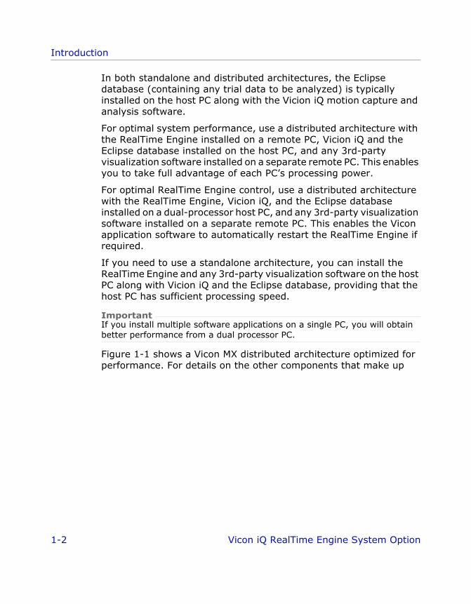
For optimal system performance, use a distributed architecture with the RealTime Engine installed on a remote PC, Vicion iQ and the Eclipse database installed on the host PC, and any 3rd-party visualization software installed on a separate remote PC. This enables you to take full advantage of each PC’s processing power.
For optimal RealTime Engine control, use a distributed architecture with the RealTime Engine, Vicion iQ, and the Eclipse database installed on a dual-processor host PC, and any 3rd-party visualization software installed on a separate remote PC. This enables the Vicon application software to automatically restart the RealTime Engine if required.
If you need to use a standalone architecture, you can install the RealTime Engine and any 3rd-party visualization software on the host PC along with Vicion iQ and the Eclipse database, providing that the host PC has sufficient processing speed.
ImportantIf you install multiple software applications on a single PC, you will obtain better performance from a dual processor PC.
Figure 1-1 shows a Vicon MX distributed architecture optimized for performance. For details on the other components that make up
1-2 Vicon iQ RealTime Engine System Option
Introduction
ViconiQ_Option_RTE.book Page 3 Tuesday, June 21, 2005 2:53 PM
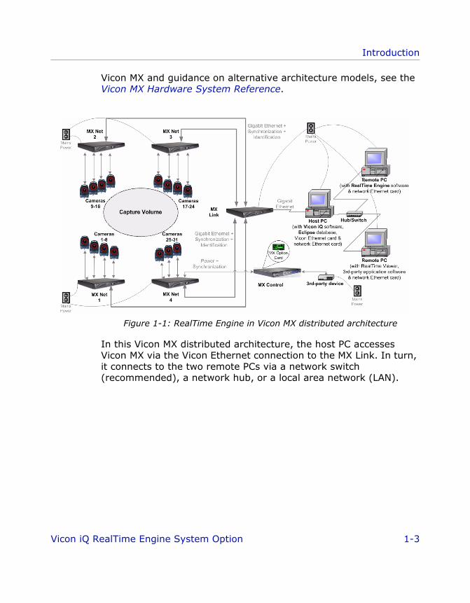
Vicon MX and guidance on alternative architecture models, see the Vicon MX Hardware System Reference.
Figure 1-1: RealTime Engine in Vicon MX distributed architecture
In this Vicon MX distributed architecture, the host PC accesses Vicon MX via the Vicon Ethernet connection to the MX Link. In turn, it connects to the two remote PCs via a network switch (recommended), a network hub, or a local area network (LAN).
Vicon iQ RealTime Engine System Option 1-3
Introduction
ViconiQ_Option_RTE.book Page 4 Tuesday, June 21, 2005 2:53 PM
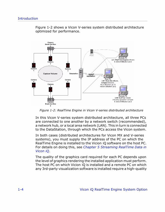
Figure 1-2 shows a Vicon V-series system distributed architecture optimized for performance.
Figure 1-2: RealTime Engine in Vicon V-series distributed architecture
In this Vicon V-series system distributed architecture, all three PCs are connected to one another by a network switch (recommended), a network hub, or a local area network (LAN). This in turn is connected to the DataStation, through which the PCs access the Vicon system.
In both cases (distributed architectures for Vicon MX and V-series systems), you must supply the IP address of the PC on which the RealTime Engine is installed to the Vicion iQ software on the host PC. For details on doing this, see Chapter 5 Streaming RealTime Data in Vicon iQ.
The quality of the graphics card required for each PC depends upon the level of graphics rendering the installed application must perform. The host PC on which Vicion iQ is installed and a remote PC on which any 3rd-party visualization software is installed require a high-quality
1-4 Vicon iQ RealTime Engine System Option
Introduction
ViconiQ_Option_RTE.book Page 5 Tuesday, June 21, 2005 2:53 PM
graphics card. The quality of the graphics card is not as important on the remote PC on which the RealTime Engine is installed.
ImportantWhether you implement a distributed or a standalone architecture for your Vicon system, the actual specification of the PCs you use depends on your application requirements. In all cases, Vicon application software requires a PC with an Intel processor. Since Intel processors are used in Vicon development and testing, Vicon applications are optimized for this processor type. For further initial guidance, see PC Specifications and Recommendations for Vicon Software" (Answer ID=824). For details on using VOS (Vicon Online Support), see Appendix E Support Resources. Your Vicon Sales representative or your nearest agent or distributor can help you to identify the requirements for your specific needs.
Real-time Data Acquisition and Streaming
Real-time data acquisition and streaming is a separate process from that for the motion data capture for offline viewing and processing in Vicion iQ. The two processes can be run at the same time, so that the Vicon system captures offline data and streams real-time data simultaneously (for details on offline motion capture in Vicon MX, see the Vicon iQ System Reference; for V-series systems, see The Vicon Manual). The RealTime Engine runs in the background, enabling you to view the data in your chosen visualization application as it is being streamed through the Vicon system.
The RealTime Engine requires subject-specific Vicon Skeleton (.vsk) files. These are generated by Vicion iQ, based on one or more trial data captures and a Vicon Skeleton Template (.vst) file. For further details on .vst and .vsk files, see Vicon File Types used in RealTime on page 1-6.
The RealTime Engine uses the .vsk file to track markers on the subject in real time and to label reconstructions. The real-time data can then be streamed, visualized, analyzed, or manipulated in Vicion iQ or 3rd-party applications.
To incorporate Vicon real-time data into 3rd-party applications, you may require a Vicon plug-in for the application you are using. If one is not available, you can use the RealTime Engine Software Developers Kit (SDK) to create your own plug-in. In Vicon MX
Vicon iQ RealTime Engine System Option 1-5
Introduction
ViconiQ_Option_RTE.book Page 6 Tuesday, June 21, 2005 2:53 PM
systems, this is automatically installed in the folder C:\Program Files\Vicon\SDK\RealTime. In Vicon V-series systems, you must select the SDK option when you install the RealTime Engine.
For details on using the RealTime Engine SDK, see the documentation provided in that folder. For details on 3rd-party CG applications that are compatible with Vicon RealTime data, see the VOS topic "3rd-party computer graphics software applications support for Vicon Offline and RealTime data" (Answer ID=8). For details on using VOS (Vicon Online Support), see Appendix E Support Resources.
Vicon File Types used in RealTime
The following types of file are used during real-time data acquisition and streaming:
• .cp filesA Vicon camera Calibration Parameters (.cp) file contains the calibration parameters specified for a set of Vicon cameras. This file is created during camera calibration and used when data from these cameras is processed.
• .c3d filesA Vicon .c3d file contains, among other details, the 3D reconstructions of video data. This file is created when video data is captured by Vicon motion capture systems and then reconstructed and saved in the Vicion iQ software.
• .trial filesA Vicon .trial file contains all trial data (e.g. rigid body, virtual point, and kinematic data). This file is created when the real-time stream is acquired by Vicon motion capture systems and processed in the Vicion iQ software.
• .vst filesA Vicon Skeleton Template (.vst) file contains a kinematic model that describes the generic relationships between segments and joints and the Vicon markers for a certain type of subject.
For example, a .vst file may be used to represent a human being. For details on the format and structure of .vst files, see Appendix B Vicon Skeleton Template (.vst) Files.
1-6 Vicon iQ RealTime Engine System Option
Introduction
ViconiQ_Option_RTE.book Page 7 Tuesday, June 21, 2005 2:53 PM
Sample .vst files are provided under the Vicion iQ Models folder (by default, C:\Program Files\Vicon \Models\VICON iQ 2.0). The files iQProductionExample_V5.vst and iQ_HumanRTKM_V1.vst describe a kinematic model and marker arrangement for human subjects. They are suitable for general use.
For details on where on a subject to place the markers to correspond with the labels defined in the sample .vst files, see Appendix C Marker Placement in Vicon iQ.
• .vsk filesA Vicon Skeleton (.vsk) file contains a kinematic model that describes the relationships between the segments, joints, and Vicon markers for a specific subject of the type described in the .vst file.
For example, if the .vst file represents a human being, the .vsk file contains a model of an individual person.
During the subject calibration process, Vicion iQ compares the generic model described in the .vst file against the movement of markers attached to a subject during a trial capture and produces a .vsk file for that specific subject. The RealTime Engine uses the .vsk file to track and label markers and segments for that person in real time.
You can use any of the supplied .vst files or create your own to suit your particular needs.
ImportantWhere they appear in multiple files, the names of markers, joints, and segments must exactly match (both in spelling and capitalization) in associated .c3d, .trial, .vst, and .vsk files.
Real-time Data Acquisition and Streaming Workflow
The basic workflow for real-time data streaming in Vicion iQ involves these steps:
1. Configure the RealTime Engine in Vicion iQ.
2. Set up Vicion iQ to prepare RealTime subjects.
3. Prepare a RealTime subject in Vicion iQ.
Vicon iQ RealTime Engine System Option 1-7
Introduction
RTE_iQ_Intro.fm Page 8 Tuesday, June 21, 2005 4:25 PM
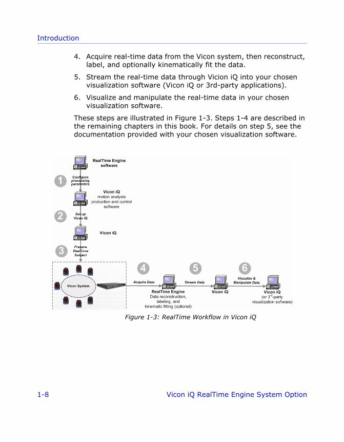
4. Acquire real-time data from the Vicon system, then reconstruct, label, and optionally kinematically fit the data.
5. Stream the real-time data through Vicion iQ into your chosen visualization software (Vicon iQ or 3rd-party applications).
6. Visualize and manipulate the real-time data in your chosen visualization software.
These steps are illustrated in Figure 1-3. Steps 1-4 are described in the remaining chapters in this book. For details on step 5, see the documentation provided with your chosen visualization software.
Figure 1-3: RealTime Workflow in Vicon iQ
1-8 Vicon iQ RealTime Engine System Option

ViconiQ_Option_RTE.book Page 1 Tuesday, June 21, 2005 2:53 PM
22Conf igur ing the Rea lT ime Engine
This chapter explains the first step of the real-time data acquisition and streaming workflow: configuring the RealTime Engine in Vicion iQ.
This involves configuring parameters and system settings for the RealTime Engine.
Configuring RealTime Engine Parameters
You can view and configure settings and parameters for the RealTime Engine in the RealTime Engine - Edit Options dialog box, as shown in Figure 2-1.
Figure 2-1: RealTime Engine - Edit Options dialog box in Vicon iQ
RealTime parameters enable you to control the way the RealTime Engine acquires, reconstructs, labels, and kinematically fits 3D data for selected RealTime subjects and then streams it to your chosen
Vicon iQ RealTime Engine System Option 2-1

Configuring the RealTime Engine
ViconiQ_Option_RTE.book Page 2 Tuesday, June 21, 2005 2:53 PM
visualization software. The default settings are sufficient for most normal motion-capture and processing situations, but you can change any of these to suit your particular requirements.
Opening the RealTime Engine - Edit Options Dialog Box
This section describes how to open the RealTime Engine - Edit Options dialog box from either the RealTime Config activity bar under the Setup operating mode, or from the RealTime Engine control bar under the Setup, Calibrate, or Capture operating modes in Vicion iQ.
To open the dialog box from the RealTime Config activity bar:1. From the Vicon iQ operating mode bar, click Setup.
2. In the Setup operating mode, click the RealTime Config activity bar, as shown in Figure 2-2.
Figure 2-2: RealTime Config activity bar in Vicon iQ
3. In the Realtime Engine Parameters configuration area, click Edit to display the RealTime Engine - Edit Options dialog box.
2-2 Vicon iQ RealTime Engine System Option
Configuring the RealTime Engine
ViconiQ_Option_RTE.book Page 3 Tuesday, June 21, 2005 2:53 PM
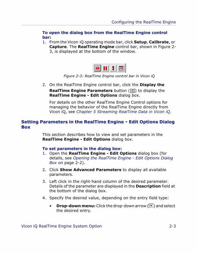
To open the dialog box from the RealTime Engine control bar:1. From the Vicon iQ operating mode bar, click Setup, Calibrate, or
Capture. The RealTime Engine control bar, shown in Figure 2-3, is displayed at the bottom of the window.
Figure 2-3: RealTime Engine control bar in Vicon iQ
2. On the RealTime Engine control bar, click the Display the RealTime Engine Parameters button ( ) to display the RealTime Engine - Edit Options dialog box.
For details on the other RealTime Engine Control options for managing the behavior of the RealTime Engine directly from Vicon iQ, see Chapter 5 Streaming RealTime Data in Vicon iQ.
Setting Parameters in the RealTime Engine - Edit Options Dialog Box
This section describes how to view and set parameters in the RealTime Engine - Edit Options dialog box.
To set parameters in the dialog box:1. Open the RealTime Engine - Edit Options dialog box (for
details, see Opening the RealTime Engine - Edit Options Dialog Box on page 2-2).
2. Click Show Advanced Parameters to display all available parameters.
3. Left click in the right-hand column of the desired parameter. Details of the parameter are displayed in the Description field at the bottom of the dialog box.
4. Specify the desired value, depending on the entry field type:
• Drop-down menu: Click the drop-down arrow ( ) and select the desired entry.
Vicon iQ RealTime Engine System Option 2-3

Configuring the RealTime Engine
ViconiQ_Option_RTE.book Page 4 Tuesday, June 21, 2005 2:53 PM
If the Macro button is enabled and is pressed in ( ), the drop-down list contains special, predefined entries.
If the Macro button is enabled but is not pressed in ( ), the drop-down list is replaced by an entry field in which you can type in the desired value.
• File name: Leave the current value, or click the Macro button
and then the Browse button ( ) and navigate to the desired file.
• Text Box: Overtype the existing value.
For details of the values that can be specified for a given parameter, see Appendix A RealTime Engine Parameters.
5. When you have specified all the desired parameters, press OK to accept the settings and close the dialog box. The RealTime Engine automatically saves the settings.
ImportantYou can automatically return all of the parameters to their default values by clicking the Reset Defaults button at the bottom of the RealTime Engine - Edit Options dialog box. This affects the parameters for the entire system.
6. In the Setup operating mode, click the RealTime Config activity bar then in the RealTime Engine Parameters configuration area, click Save. The Select RealTime Parameter file dialog box is displayed.
7. In the Select RealTime Parameter file dialog box, ensure the Save in path is set to the current session in your Eclipse database and click Save to save the parameter file and close the dialog box.
2-4 Vicon iQ RealTime Engine System Option

Configuring the RealTime Engine
ViconiQ_Option_RTE.book Page 5 Tuesday, June 21, 2005 2:53 PM
Configuring RealTime Engine System Settings
You view and configure the connections to the Vicon system components that are to provide camera data to the RealTime Engine in the Hardware Config activity bar under the Setup operating mode.
To specify system settings in the Hardware Config activity bar:1. From the Vicon iQ operating mode bar, click Setup.
2. In the Setup operating mode, click the Hardware Config activity bar.
3. In the System Type configuration area, click the appropriate button for your Vicon system (the details displayed on the activity bar reflect the selected system):
• V Series: Vicon V-series systems that provide RealTime support through the following Vicon DataStations: V460, V6, V612, V624, and V8i.
Figure 2-4: Hardware Config activity bar for Vicon V-series systems
Vicon iQ RealTime Engine System Option 2-5

Configuring the RealTime Engine
ViconiQ_Option_RTE.book Page 6 Tuesday, June 21, 2005 2:53 PM
• Vicon MX: Vicon MX
Figure 2-5: Hardware Config activity bar for Vicon MX
4. Specify the system connections in the following configuration area, depending on your Vicon system type:
DataStation Setup (Vicon V-series systems)
• Datastation IP Address: The IP address or the PC network name for the Vicon DataStation.
Device Setup (Vicon MX)
• iQ IP Address: The IP address or the PC network name for the remote PC on which Vicon iQ is installed.
A value is not required if the RealTime Engine is installed on the host PC with Vicon iQ. You need specify a value only if the RealTime Engine is installed on a separate, remote PC.
2-6 Vicon iQ RealTime Engine System Option
ViconiQ_Option_RTE.book Page 1 Tuesday, June 21, 2005 2:53 PM
33Se t t ing Up V icon iQ
This chapter explains the second step of the real-time data acquisition and streaming workflow: setting up Vicion iQ to prepare a RealTime subject. Before starting this step, ensure that the RealTime Engine has been configured for your requirements as described in Chapter 2 Configuring the RealTime Engine.
This step involves gathering the require materials and creating the necessary trial types for the initial trials you must capture to prepare a RealTime subject in Workstation (with or without the Plug-in Gait option).
Gathering Required Equipment and Files
You need the following items in order to prepare a Vicon RealTime subject in Vicon iQ:
• Fully calibrated Vicon system. For details on preparing your Vicon MX system for use, see the Vicon MX System Setup document. For setup details on setting up Vicon V-series systems, see "Preparation" in The Vicon Manual.
• Vicon iQ and the RealTime Engine.
• Eclipse database with the desired hierarchy (e.g. top-level classification, subject, session and trial nodes) to hold the data you will capture. For details on working with Eclipse, see "Preparation" in The Vicon Manual.
• Vicon markers. Ensure that you have the appropriate size and quantity for the marker arrangement specified in the .vst file to be used.
• Vicon Skeleton Template (.vst) file for your subject type. For details on .vst files, see Chapter 1 Introduction.
Vicon iQ RealTime Engine System Option 3-1

Setting Up Vicon iQ
ViconiQ_Option_RTE.book Page 2 Tuesday, June 21, 2005 2:53 PM
Understanding Trial Types
A pipeline contains one or more operations to be performed on the data for a specific type of trial. Once created, this pipeline is available for use on any future trials.
In order to prepare a RealTime subject in Vicion iQ, you must capture a specific type of dynamic trial for your subject, known as a Range of Motion (RoM) trial. This type of trial enables Vicon iQ to determine the location of and measurements between key markers and to assign labels to the marker images captured. This is required for the labeling and subject calibration processes defined in your pipeline.
A RoM trial is a short data capture (typically 15-30 seconds) during which the subject moves each limb and joint to be captured through its full range of motion at least once. For example, hinge joints such as knees and elbows are flexed to their fully bent position and then straightened. Ball-and-socket joints such as wrists and ankles are swiveled a full rotation.
Ensure that the RoM trial includes movements to match any specific moves that will be included in the data captures you intend to take. For example, if you intend to capture the subject hitting a ball with a bat, executing a dance step, or performing stunts, gymnastics, or martial arts, then have the subject perform similar movements during the RoM trial.
Depending on the subject’s level of coordination and experience, the movements of different joints can be combined to reduce the trial time. The movements can be fast, but must include repeated hand and foot movement. For example, have the subject continue to flex and extend their wrists while performing other movements during the RoM trial. The repetition of quick, key joint motions will produce best results.
Through a RoM trial, Vicion iQ learns the subject’s physical makeup and capabilities. The more complete the RoM trial (in terms of including all required movements, not excessive repetitions or a lengthy trial time), the better the real-time kinematic model Vicion iQ produces, and thus the better the reconstructing and labeling performance.
3-2 Vicon iQ RealTime Engine System Option

Setting Up Vicon iQ
ViconiQ_Option_RTE.book Page 3 Tuesday, June 21, 2005 2:53 PM
To have the subject perform basic movements for a Vicon iQ RealTime RoM trial:1. Subject starts by standing in a neutral pose.
The actual posture for a neutral pose depends upon the definition of the zero position for key joints in the kinematic model described in the associated Vicon Skeleton Template (.vst) file. For example, in the iQProductionExample_V5.vst sample file, the neutral pose assumes that the subject stands upright with the head level and looking straight ahead, shoulders relaxed (neither hunched forward nor pressed backward), arms hanging loosely by the sides with wrists straight and palms facing inward, pelvis level, and feet flat on the floor and pointing forward.
Examples of popular forms of the neutral pose are:
• T-pose: The subject stands in the basic neutral pose and raises the arms out straight to the sides with palms facing down (in a position in the shape of a T). The T-pose is often used in RealTime RoM trials in Vicon iQ if the data will later be used for modifying the RealTime subject in computer graphics packages.
• Motorcycle pose: The subject stands in the basic neutral pose with the knees slightly flexed, and the arms out straight to the sides, elbows bent forward, and hands in front with palms facing down (in a position similar to holding the handlebars of a motorcycle).
2. Subject rolls the head, rotates the shoulders, flexes and extends the elbows, flexes and extends the wrists, and circles the wrists.
3. Subject twists left and right then bends forwards and backwards from the waist.
4. Subject swivels the hips and performs some hip flexion movements. Ensure that subjects do not put their hands on their hips as that may obscure markers on the waist.
5. Subject flexes and extends the knees and circles the ankles.
Vicon iQ RealTime Engine System Option 3-3
Setting Up Vicon iQ
ViconiQ_Option_RTE.book Page 4 Tuesday, June 21, 2005 2:53 PM
6. Subject performs any specific movements to be included in actual trials.
ImportantSome 3rd-party applications may require a specific pose for the data they are to process. For details on required poses, see the documentation supplied with the 3rd-party application.
Creating a RealTime Processing Pipeline for RoM Trials
This section describes how to set up a pipeline for processing RoM trials to be captured in Vicon iQ. It provides general instructions on how to add an operation to a pipeline, followed by specific instructions on the operations to be added to this RoM trial processing pipeline.
ImportantIn previous versions of Vicon iQ, some operations were available only from a processing pipeline. In Vicon iQ 2.0, you can now control some of these operations directly from activity bars if you prefer. For example, you can specify reconstruction parameters in the Reconstruction activity bar in the Post Processing operating mode (for details on doing this while capturing a RoM trial, see Chapter 4 Preparing a RealTime Subject in Vicon iQ) as well as from the pipeline. Options that can be specified from activity bars are described in the relevant sections later in this chapter; this section describes those options available only from the pipeline.
To add an operation to a pipeline in Vicon iQ:1. In the Post Processing operating mode, click the Pipeline
activity bar.
2. On the Pipeline Control tool bar, click the Add Operation To
Pipeline button ( ).
3. In the Available Operations dialog box, double-click the operation to be added (options are listed in alphabetical order). The specified operation is displayed in the list in the Pipeline Control configuration area.
4. Click Done to close the Available Operations dialog box.
3-4 Vicon iQ RealTime Engine System Option
Setting Up Vicon iQ
ViconiQ_Option_RTE.book Page 5 Tuesday, June 21, 2005 2:53 PM
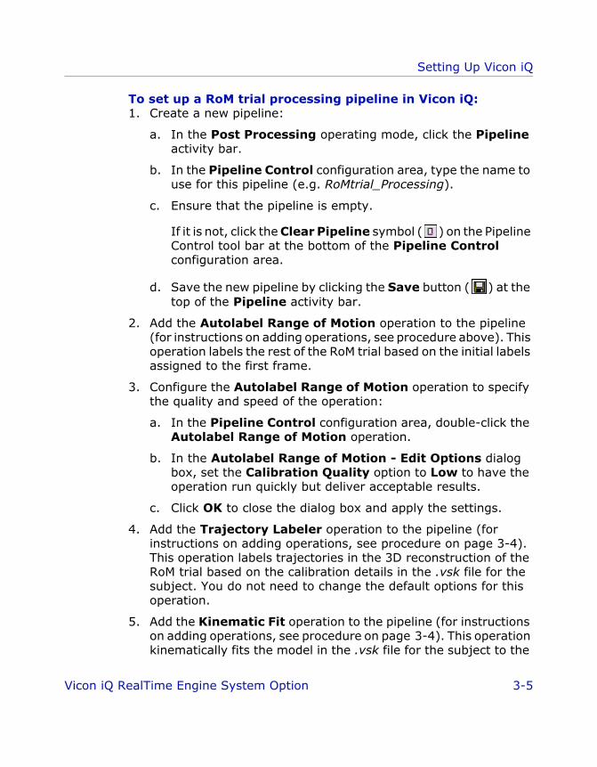
To set up a RoM trial processing pipeline in Vicon iQ:1. Create a new pipeline:
a. In the Post Processing operating mode, click the Pipeline activity bar.
b. In the Pipeline Control configuration area, type the name to use for this pipeline (e.g. RoMtrial_Processing).
c. Ensure that the pipeline is empty.
If it is not, click the Clear Pipeline symbol ( ) on the Pipeline Control tool bar at the bottom of the Pipeline Control configuration area.
d. Save the new pipeline by clicking the Save button ( ) at the top of the Pipeline activity bar.
2. Add the Autolabel Range of Motion operation to the pipeline (for instructions on adding operations, see procedure above). This operation labels the rest of the RoM trial based on the initial labels assigned to the first frame.
3. Configure the Autolabel Range of Motion operation to specify the quality and speed of the operation:
a. In the Pipeline Control configuration area, double-click the Autolabel Range of Motion operation.
b. In the Autolabel Range of Motion - Edit Options dialog box, set the Calibration Quality option to Low to have the operation run quickly but deliver acceptable results.
c. Click OK to close the dialog box and apply the settings.
4. Add the Trajectory Labeler operation to the pipeline (for instructions on adding operations, see procedure on page 3-4). This operation labels trajectories in the 3D reconstruction of the RoM trial based on the calibration details in the .vsk file for the subject. You do not need to change the default options for this operation.
5. Add the Kinematic Fit operation to the pipeline (for instructions on adding operations, see procedure on page 3-4). This operation kinematically fits the model in the .vsk file for the subject to the
Vicon iQ RealTime Engine System Option 3-5

Setting Up Vicon iQ
ViconiQ_Option_RTE.book Page 6 Tuesday, June 21, 2005 2:53 PM
3D reconstruction of the RoM trial. You do not need to change the default options for this operation.
6. Save the pipeline by clicking the Save button ( ) at the top of the Pipeline activity bar.
Preparing to Capture a RoM Trial
Each time you want to calibrate a new subject in Vicon iQ, you must capture a RoM trial. This enables Vicon iQ to determine the location of and measurements between key markers attached to the subject. During its autolabel process, Vicion iQ identifies the relationship between the labels defined in the associated .vst file and the marker images captured during the RoM trial.
To prepare to capture a RoM trial in Vicon iQ:1. Open either the session node you previously created to hold the
data for this RoM trial, or a node for a previous trial within the session, by clicking the Data Management operating mode to display the Eclipse Data Directory browser and then double-clicking the icon for the desired session or trial.
2. On the Vicon iQ operating mode bar, click Capture.
3. In the Capture operating mode, click the Capture activity bar.
4. Complete the following configuration areas of the Capture activity bar:
1. Active Session (From Eclipse): Ensure that the desired Eclipse session is displayed.
2. Provide Trial Information: Complete the following details for the RoM trial to be captured:
• Name: By default, this displays the name of the Eclipse database node that you selected in step 2. If the Auto increment trial number option (see below) was selected before the Eclipse database node was selected, the trial number suffix is updated. Note that this is not a dynamic option; if you select or clear this option once the session has been loaded, the trial name is not immediately incremented.
3-6 Vicon iQ RealTime Engine System Option
Setting Up Vicon iQ
ViconiQ_Option_RTE.book Page 7 Tuesday, June 21, 2005 2:53 PM
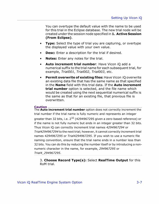
You can overtype the default value with the name to be used for this trial in the Eclipse database. The new trial node will be created under the session node specified in 1. Active Session (From Eclipse).
• Type: Select the type of trial you are capturing, or overtype the displayed value with your own value.
• Desc: Enter a description for the trial if desired.
• Notes: Enter any notes for the trial.
• Auto increment trial number: Have Vicon iQ add a numerical suffix to the trial name for each subsequent trial, for example, Trial001, Trial002, Trial003, etc.
• Permit overwrite of existing files: Have Vicon iQ overwrite an existing data file that has the same name as that specified in the Name field with this trial data. If the Auto increment trial number option is selected, and the file name which would be created using the next sequential numerical suffix is the same as that for an existing file, that previous file is overwritten.
CautionThe Auto increment trial number option does not correctly increment the trial number if the trial name is fully numeric and represents an integer
greater than 32 bits, i.e. 232 (4294967295 given a zero-based reference) or if the name is not fully numeric but ends in an integer greater than 32 bits. Thus Vicon iQ can correctly increment trial names 4294967294 or Trial4294967294 to the next trial; however, it cannot correctly increment trial names 4294967295 or Trial4294967295. If you wish to use a numeric file naming convention, ensure that the trial name ends in a number less than 32 bits. You can do this by reducing the number itself or by introducing a non-numeric character in the name, for example, 294967295 or Trial4_294967295.
3. Choose Record Type(s): Select RealTime Output for this RoM trial.
Vicon iQ RealTime Engine System Option 3-7

Setting Up Vicon iQ
ViconiQ_Option_RTE.book Page 8 Tuesday, June 21, 2005 2:53 PM
3-8 Vicon iQ RealTime Engine System Option

ViconiQ_Option_RTE.book Page 1 Tuesday, June 21, 2005 2:53 PM
44P repar ing a Rea lT ime Subject in V icon iQ
This chapter explains the third step of the real-time data acquisition and streaming workflow: preparing a RealTime subject. Before starting this step, ensure that the RealTime Engine has been configured for your requirements as described in Chapter 2 Configuring the RealTime Engine.
A RealTime subject requires a kinematic model of an individual whose movements are to be processed in Vicon motion capture software. The kinematic model contains definitions of the individual’s bones, joints, degrees of freedom, and constraints as well as how the associated Vicon markers relate to these elements of the kinematic model.
Preparing a RealTime subject in Vicon iQ involves capturing trial data for the subject wearing Vicon markers and then calibrating a model based on the captured motion data, the subject’s actual measurements, and a generic Vicon Skeleton Template (.vst) file that contains a predefined kinematic model of the subject type. The end result is written to a Vicon Skeleton (.vsk) file that contains a kinematic model of the specific subject (<subject_name>.vsk), which you can use to visualize and analyze data for your RealTime Subject in Vicon iQ as described in Chapter 5 Streaming RealTime Data in Vicon iQ.
Vicon iQ RealTime Engine System Option 4-1
Preparing a RealTime Subject in Vicon iQ
ViconiQ_Option_RTE.book Page 2 Tuesday, June 21, 2005 2:53 PM
Preparing a RealTime Subject in Vicon iQ
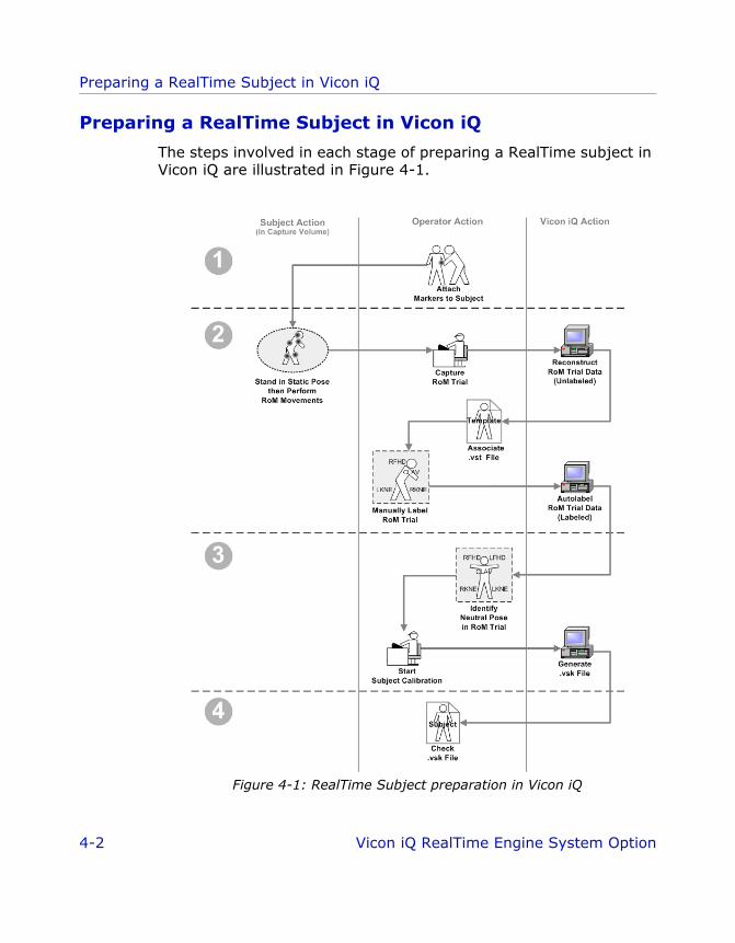
The steps involved in each stage of preparing a RealTime subject in Vicon iQ are illustrated in Figure 4-1.
Figure 4-1: RealTime Subject preparation in Vicon iQ
4-2 Vicon iQ RealTime Engine System Option
Preparing a RealTime Subject in Vicon iQ
ViconiQ_Option_RTE.book Page 3 Tuesday, June 21, 2005 2:53 PM
The following sections describe the steps in each of these stages:
1. Attaching Vicon Markers to the Subject
2. Capturing a RoM Trial on page 4-4
3. Generating a .vsk File on page 4-13
4. Checking the Subject Calibration Results on page 4-18
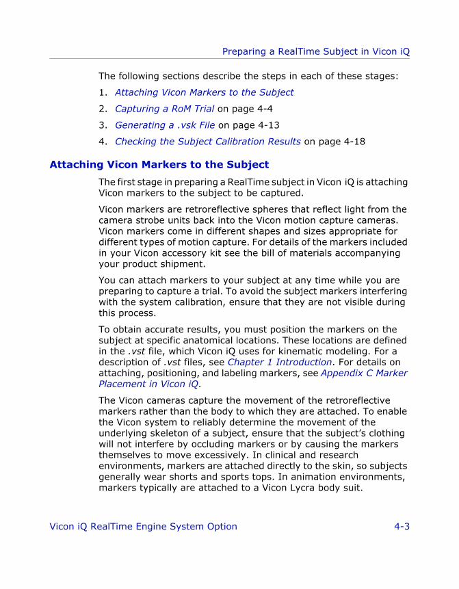
Attaching Vicon Markers to the Subject
The first stage in preparing a RealTime subject in Vicon iQ is attaching Vicon markers to the subject to be captured.
Vicon markers are retroreflective spheres that reflect light from the camera strobe units back into the Vicon motion capture cameras. Vicon markers come in different shapes and sizes appropriate for different types of motion capture. For details of the markers included in your Vicon accessory kit see the bill of materials accompanying your product shipment.
You can attach markers to your subject at any time while you are preparing to capture a trial. To avoid the subject markers interfering with the system calibration, ensure that they are not visible during this process.
To obtain accurate results, you must position the markers on the subject at specific anatomical locations. These locations are defined in the .vst file, which Vicon iQ uses for kinematic modeling. For a description of .vst files, see Chapter 1 Introduction. For details on attaching, positioning, and labeling markers, see Appendix C Marker Placement in Vicon iQ.
The Vicon cameras capture the movement of the retroreflective markers rather than the body to which they are attached. To enable the Vicon system to reliably determine the movement of the underlying skeleton of a subject, ensure that the subject’s clothing will not interfere by occluding markers or by causing the markers themselves to move excessively. In clinical and research environments, markers are attached directly to the skin, so subjects generally wear shorts and sports tops. In animation environments, markers typically are attached to a Vicon Lycra body suit.
Vicon iQ RealTime Engine System Option 4-3

Preparing a RealTime Subject in Vicon iQ
ViconiQ_Option_RTE.book Page 4 Tuesday, June 21, 2005 2:53 PM
To attach Vicon markers to the subject:1. Select the appropriate size and quantity of Vicon markers to be
used.
2. Physically attach Vicon markers to the subject, according to the .vst file you are using.
Ensure that you attach them securely, so they do not move or fall off during the trial. For further guidance on methods of attaching markers, see "Preparation" in The Vicon Manual.
Capturing a RoM Trial
The second stage in creating a RealTime subject in Vicon iQ is capturing a RoM trial. This stage requires the data capture settings you previously set up and the trial processing pipeline you previously created (for details on preparing to capture a RoM trial and creating a processing pipeline, see Chapter 3 Setting Up Vicon iQ). The Vicon markers must still be attached to the subject as they were in the first stage (for details, see Attaching Vicon Markers to the Subject on page 4-3).
A RoM trial for RealTime in Vicion iQ involves a short data capture (typically 15-30 seconds) during which the subject moves the limbs and joints to be captured through their full range of motion. This enables the Vicon system to track the movement of key markers and Vicion iQ to determine the measurements between them. Vicion iQ then performs the pipeline operations you defined to reconstruct and label the marker images. For details on RoM trials and processing pipelines, see Chapter 3 Setting Up Vicon iQ).
To capture a RoM trial in Vicon iQ:1. Ensure the Vicon markers are still attached to the subject standing
in the capture volume.
2. On the Vicon iQ operating mode bar, click Capture.
3. In the Capture operating mode, click the Capture activity bar.
4. Check your previously specified trial data capture settings (for details, see Chapter 3 Setting Up Vicon iQ).
5. In the 4. Capture! configuration area, click Start.
4-4 Vicon iQ RealTime Engine System Option

Preparing a RealTime Subject in Vicon iQ
ViconiQ_Option_RTE.book Page 5 Tuesday, June 21, 2005 2:53 PM
6. In the capture volume, have the subject start in a neutral pose (such as the T-pose) and then perform the required RoM movements. The Vicon cameras capture the subject’s movements.
ImportantYou may wish to have the subject rehearse the movements to be performed in advance, or you may prefer to talk the subject through them as the trial is captured. For guidance on the types of movements typically performed during RoM trials for RealTime in Vicon iQ, see Chapter 3 Setting Up Vicon iQ.
7. In the 3D Workspace, check that any Masks (Vicon V-series systems) or Threshold Grids (Vicon MX) you previously created under the Setup operating mode are hiding unwanted reflections.
8. In the 4. Capture! configuration area of the Capture activity bar, click Stop.
9. Reconstruct the 2D camera data:
a. In the Post Processing operating mode, click the Reconstruction activity bar.
b. On the workspace configuration menu bar, click Camera, and then on the Cams menu, click a camera number to open a camera view pane.
c. In the Reconstruction Parameters configuration area, leave the parameters set to their default values, or change them according to your requirements.
d. Click Advanced, to display the CircleFit, Reconstruct, Trajectory Fit Frame Range - Edit Options dialog box. Specify any additional reconstruction parameters and click OK.
For details on these parameters, see Appendix A RealTime Engine Parameters.
ImportantIf desired, you can save the values you specified in the Reconstruction Parameters configuration area and dialog box to a Pipeline operation by clicking the Create Pipeline Operation button. You can then run this CircleFit, Reconstruct, Trajectory Fit Frame Range operation from the
Vicon iQ RealTime Engine System Option 4-5

Preparing a RealTime Subject in Vicon iQ
ViconiQ_Option_RTE.book Page 6 Tuesday, June 21, 2005 2:53 PM
Pipeline activity bar (also in the Post Processing operating mode) for future reconstructions.
e. In the Frame Range configuration area, click Whole to reconstruct the data for the entire trial.
f. In the Reconstruct configuration area, click the Run button.
Vicon iQ starts reconstructing the captured data, indicating its progress in the status bar beneath the Reconstruct button.
When the operation is complete, the marker images in the camera view pane turn white, as shown in Figure 4-2.
Figure 4-2: RoM trial with reconstructed data
10.Associate a .vst file with the RoM trial:
a. In the Post Processing operating mode, click the Subjects activity bar.
b. In the Create New configuration area, click Create Vicon Skeleton Template (VST).
4-6 Vicon iQ RealTime Engine System Option
Preparing a RealTime Subject in Vicon iQ
ViconiQ_Option_RTE.book Page 7 Tuesday, June 21, 2005 2:53 PM
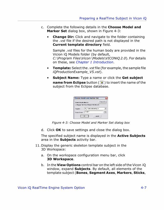
c. Complete the following details in the Choose Model and Marker Set dialog box, shown in Figure 4-3:
• Change Dir: Click and navigate to the folder containing the .vst file if the desired path is not displayed in the Current template directory field.
Sample .vst files for the human body are provided in the Vicion iQ Models folder (by default, C:\Program Files\Vicon \Models\VICONiQ 2.0). For details on these, see Chapter 1 Introduction.
• Template: Select the .vst file (for example, the sample file iQProductionExample_V5.vst).
• Subject Name: Type a name or click the Get subject name from Eclipse button ( ) to insert the name of the subject from the Eclipse database.
Figure 4-3: Choose Model and Marker Set dialog box
d. Click OK to save settings and close the dialog box.
The specified subject name is displayed in the Active Subjects area in the Subjects activity bar.
11.Display the generic skeleton template subject in the 3D Workspace:
a. On the workspace configuration menu bar, click 3D Workspace.
b. In the View Options control bar on the left side of the Vicon iQ window, expand Subjects. By default, all elements of the template subject (Bones, Segment Axes, Markers, Sticks,
Vicon iQ RealTime Engine System Option 4-7

Preparing a RealTime Subject in Vicon iQ
ViconiQ_Option_RTE.book Page 8 Tuesday, June 21, 2005 2:53 PM
Bounding Boxes, and Parameter Links) are displayed in addition to the RoM subject, as shown in Figure 4-4.
Figure 4-4: 3D Workspace with RoM and VST subjects
c. Ensure Markers and Sticks are selected and clear the other elements. The sticks will be displayed when labels are assigned to the trajectories on the RoM trial subject.
12.Manually label each marker image:
a. In the Post Processing operating mode, click the Labeling activity bar.
b. On the workspace configuration menu bar, click 3D Workspace.
c. Locate the first frame of the RoM trial in which the subject is stationary and the marker data is complete, either by dragging the Time Bar slider to the desired frame or by typing the frame number (if you know it) into the current frame box at the top left of the Time Bar.
4-8 Vicon iQ RealTime Engine System Option

Preparing a RealTime Subject in Vicon iQ
ViconiQ_Option_RTE.book Page 9 Tuesday, June 21, 2005 2:53 PM
d. Complete the following configuration areas of the Labeling activity bar to enable quick manual labeling of the first frame of the RoM trial:
• Modes: Select Sequence to automatically advance to the next label in the marker list in the Labels configuration area as you assign labels to trajectories in the 3D Workspace.
• Rules: Select Whole to force Vicon iQ to label entire 3D trajectories as you click on them in the 3D Workspace.
For more details on other options in the Modes and Rules configuration areas, see the Vicon iQ documentation.
e. In the markers list in the Labels configuration area, select the first marker in the list and then in the 3D Workspace, click the corresponding marker image on the RoM subject.
If you are using the iQHumanProduction_ExampleV5.vst sample subject template file, see Appendix C Marker Placement in Vicon iQ for details of the location of markers on the RoM subject.
When labeled, the white marker image changes color, a number is displayed next to the label in the marker list in the
Vicon iQ RealTime Engine System Option 4-9

Preparing a RealTime Subject in Vicon iQ
ViconiQ_Option_RTE.book Page 10 Tuesday, June 21, 2005 2:53 PM
Labels configuration area, and the next label is automatically selected, as shown in Figure 4-5.
Figure 4-5: Manually label marker images in Vicon iQ
The number in the markers list in the Labels configuration area is updated each time you assign that label to a marker. This enables you to check whether every label has been used or if you’ve erroneously assigned a particular label to more than one marker image. If the .vst file you have associated with the RoM trial has specific colors defined for each label, these are applied to the marker in the 3D Workspace when the label is assigned, and they are reflected in the colored box next to the number in the markers list in the activity bar.
f. In the 3D Workspace, click the marker image corresponding to the currently selected label until you have assigned all the labels.
You can check a marker’s label assignment by hovering the mouse pointer over a labeled trajectory to display a pop-up window with the name of the label and the subject’s name.
4-10 Vicon iQ RealTime Engine System Option

Preparing a RealTime Subject in Vicon iQ
ViconiQ_Option_RTE.book Page 11 Tuesday, June 21, 2005 2:53 PM
As you label more markers, a colored line is drawn between each marker until a stick figure appears. The way this figure is drawn is defined in the associated .vst file. For example, if you are using the sample file iQProductionExample_V5.vst, the stick figure is in the shape of a human skeleton, as shown in Figure 4-6.
Figure 4-6: Stick figure for manually labeled RoM trial in Vicon iQ
13.Check the manual labeling to see how well it is maintained through the trial by dragging the Time Bar slider through the entire trial and viewing it in the 3D Workspace.
You can see if any markers have become unlabeled during a portion of the trial, which can occur due to occlusions. Markers that have lost their label are highlighted in the markers list in the Labeling Control Bar. Manually assign labels to any unlabeled markers and correct any mislabeled markers.
14.Autolabel the RoM trial:
a. In the 3D Workspace, locate the first frame of the trial in which the subject is stationary and the marker data is complete by dragging the Time Bar slider to the desired frame
Vicon iQ RealTime Engine System Option 4-11

Preparing a RealTime Subject in Vicon iQ
ViconiQ_Option_RTE.book Page 12 Tuesday, June 21, 2005 2:53 PM
or by typing the frame number (if you know it) into the current frame box at the top left of the Time Bar. The Autolabel Range of Motion operation assumes that the current frame is correctly labeled.
b. Ensure that the entire range of frames is selected. On the Time Bar, drag the green handle all the way to the left and the red handle all the way to the right.
c. Click the Pipeline activity bar.
d. In the Pipeline Control configuration area, select the pipeline you previously created for processing the RoM trial (for details, see Chapter 3 Setting Up Vicon iQ).
e. In the list, right-click the Autolabel Range of Motion operation and in the displayed context menu, select Run Selected Op.
Vicon iQ starts autolabeling all of the remaining unlabeled trajectories in the RoM trial, indicating its progress in the Operation Control status bar at the bottom of the Pipeline activity bar.
When the operation is complete, an operation succeeded message is displayed in the Log window and a green check mark ( ) is displayed next to the operation in the Pipeline Control configuration area.
15. Play back the trial in the 3D Workspace:
a. In the Post Processing operating mode, click the Labeling activity bar.
b. On the Workspace Configuration menu bar, click 3D Workspace.
c. On the Time Bar, drag the slider through the entire trial and ensure that the RoM trial is fully and correctly labeled.
d. Manually assign labels to any unlabeled markers and correct any mislabeled markers.
16.Save the labeled RoM trial by selecting Save from the File menu.
The .trial file is stored in the current session folder in the Eclipse database.
4-12 Vicon iQ RealTime Engine System Option

Preparing a RealTime Subject in Vicon iQ
ViconiQ_Option_RTE.book Page 13 Tuesday, June 21, 2005 2:53 PM
Generating a .vsk File
The third stage in creating a RealTime subject in Vicon iQ is generating a Vicon Skeleton (.vsk) file for your subject. This involves calibrating the trial subject against the generic Vicon Skeleton Template (.vst) file you used to label the RoM trial in the second stage (for details, see Capturing a RoM Trial on page 4-4).
During the subject calibration process, Vicon iQ compares the definition of segments, joints, and markers for a particular type of skeleton (or object) defined in the associated .vst file to the physical segments, joints, and markers on the trial subject and generates a subject-specific .vsk file. You can use this .vsk file in subsequent data captures with the same subject.
ImportantAs the .vsk file contains details on the location of markers on the subject, if you wish to use different marker arrangements on the same subject, you must generate a unique .vsk file for each marker arrangement.
To generate a .vsk file in Vicon iQ:1. Open the labeled RoM trial in Vicon iQ (if it is not already) by
clicking the Data Management operating mode to display the Eclipse Data Directory browser and then double-clicking the icon for the desired trial.
2. Ensure that a .vst file is associated with your subject:
a. In the Post Processing operating mode, click the Subjects activity bar.
b. In the Active Subjects configuration area, confirm that (.vst) is displayed next to the subject name.
3. In the 3D Workspace, locate the first frame of the trial in which the subject is standing in the neutral pose (such as the T-pose) and the marker data is complete and correctly labeled, then mark the frame as an event:
a. Drag the Time Bar slider to the desired frame or type the frame number (if you know it) into the current frame box at the top left of the Time Bar.
Vicon iQ RealTime Engine System Option 4-13
Preparing a RealTime Subject in Vicon iQ
ViconiQ_Option_RTE.book Page 14 Tuesday, June 21, 2005 2:53 PM
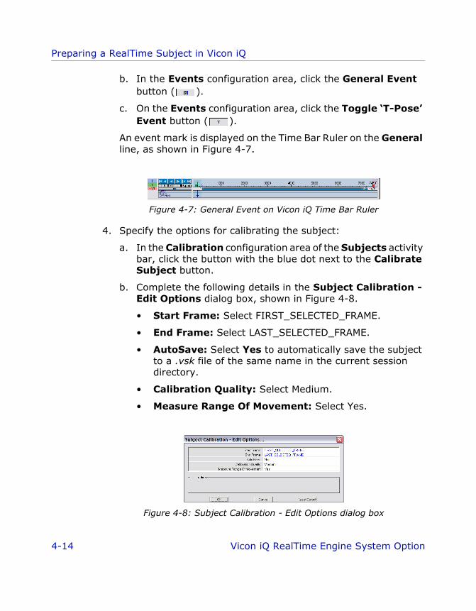
b. In the Events configuration area, click the General Event button ( ).
c. On the Events configuration area, click the Toggle ‘T-Pose’ Event button ( ).
An event mark is displayed on the Time Bar Ruler on the General line, as shown in Figure 4-7.
Figure 4-7: General Event on Vicon iQ Time Bar Ruler
4. Specify the options for calibrating the subject:
a. In the Calibration configuration area of the Subjects activity bar, click the button with the blue dot next to the Calibrate Subject button.
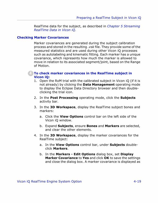
b. Complete the following details in the Subject Calibration - Edit Options dialog box, shown in Figure 4-8.
• Start Frame: Select FIRST_SELECTED_FRAME.
• End Frame: Select LAST_SELECTED_FRAME.
• AutoSave: Select Yes to automatically save the subject to a .vsk file of the same name in the current session directory.
• Calibration Quality: Select Medium.
• Measure Range Of Movement: Select Yes.
Figure 4-8: Subject Calibration - Edit Options dialog box
4-14 Vicon iQ RealTime Engine System Option

Preparing a RealTime Subject in Vicon iQ
ViconiQ_Option_RTE.book Page 15 Tuesday, June 21, 2005 2:53 PM
c. Click OK to save settings and close the dialog box.
d. If you wish to change the autocolor to be used for the markers in the .vsk, click the color button next to the Calibrate Subject button and select the desired color. This is useful for assigning a unique color to each of multiple subjects.
5. In the Calibration configuration area, click Calibrate Subject.
Vicon iQ starts calibrating the labeled 3D reconstructions, indicating its overall progress and an error value in the progress bar at the bottom of the Calibration configuration area. The error value indicates the average root mean squared (RMS) error between where the Vicon markers are on the subject’s body and where the subject calibration process believes the markers to be on the current kinematic model defined in the .vst file. This error value decreases during the subject calibration process until processing is complete and the final value is displayed. When the operation is complete, an operation succeeded message is displayed in the Log window
ImportantThe error value for a good subject calibration typically is less than 10.00 mm, though a typical subject calibration may vary between 7-15 mm. If the log shows a significantly higher value, check the marker placement and labeling. If the error values are still excessive, check that the associated .vst file reflects the real kinematics of your subject type. Make any necessary changes, and then generate a new .vsk file (for details, see Generating a .vsk File on page 4-13).
6. Display the calibrated subject in the 3D Workspace:
a. In the View Options control bar on the left side of the Vicon iQ window, expand Subjects.
b. Select all elements of the newly calibrated subject (Bones, Segment Axes, Markers, Sticks, Bounding Boxes, and Parameter Links).
c. In the Pose Display configuration area of the Subjects activity bar, click Mean.
The newly calibrated subject is displayed in its average pose, which has been derived from the RoM trial and the subject calibration process. This pose should be a natural looking pose for
Vicon iQ RealTime Engine System Option 4-15

Preparing a RealTime Subject in Vicon iQ
ViconiQ_Option_RTE.book Page 16 Tuesday, June 21, 2005 2:53 PM
a human, with all segments/joints in an approximate average position and rotation in relation to the previously processed RoM trial. The newly calibrated subject is displayed in front of the labeled 3D reconstruction, as shown in Figure 4-9.
Figure 4-9: Calibrated Subject and labeled markers in 3D Workspace
7. Save the calibrated subject file:
a. In the Export configuration area of the Subjects activity bar, click the button with the blue dot next to the Export Vicon Skeleton (VSK) button.
b. In the Save Subject(s) - Edit Options dialog box, ensure that Use File Name is set to No. This ensures that the .vsk file is automatically exported to the current session in the Eclipse database in the same location as the RoM trial.
c. Click OK to save the settings and close the dialog box.
d. Click Export Calibrated Subject (VSK).
8. Save the trial data by selecting Save from the File menu.
4-16 Vicon iQ RealTime Engine System Option

Preparing a RealTime Subject in Vicon iQ
ViconiQ_Option_RTE.book Page 17 Tuesday, June 21, 2005 2:53 PM
The .trial file is stored in the current session folder in the Eclipse database. The new subject appears in the list of available objects in the Active Objects tab under the Capture operating mode.
Recalibrating Markers in a .vsk File
Whenever you capture a new trial for a previously prepared RealTime subject, the Vicon markers must be in the same position on the subject as they were when you generated the .vsk file for that subject in Vicon iQ.
If the position of the markers on the subject has changed in any way, for example if markers have moved during a previous trial or if you have removed and reapplied the markers (for example, if you are running another trial on a different day), then you must recalibrate the marker positions in the .vsk file for the subject.
To recalibrate marker positions in a .vsk file:1. Attach markers to the subject, according to the .vst file you used
when you originally generated the .vsk file.
2. Have the subject stand in the capture volume.
3. In Vicon iQ, start the trial capture:
a. In the Capture operating mode, click the Capture activity bar.
b. Check your previously specified trial data capture settings (for details, see Chapter 3 Setting Up Vicon iQ).
c. In the 4. Capture! configuration area, click Start.
4. In the capture volume, have the subject perform a short RoM trial, starting in a neutral pose (such as the T-pose) and then performing the specified movements showing flexion of the main joints. For guidance on the types of movements typically performed during RoM trials, see Chapter 3 Setting Up Vicon iQ.
5. In the 4. Capture! configuration area, click Stop.
6. In the 3D Workspace, locate the first frame of the trial in which the subject is standing in the neutral pose (such as the T-pose)
Vicon iQ RealTime Engine System Option 4-17

Preparing a RealTime Subject in Vicon iQ
ViconiQ_Option_RTE.book Page 18 Tuesday, June 21, 2005 2:53 PM
and the marker data is complete and correctly labeled, and then mark the frame as an event:
a. Drag the Time Bar slider to the desired frame or type the frame number (if you know it) into the current frame box at the top left of the Time Bar.
b. In the Events configuration area, click the General Event button ( ).
c. On the Events configuration area, click the Toggle ‘T-Pose’ Event button ( ).
7. In the Post Processing operating mode, click the Subjects activity bar.
8. In the Calibration configuration area, click Recalibrate Markers.
Vicon iQ starts recalibrating the marker information in the .vsk file, indicating its progress in the status bar beneath the Recalibrate Markers button. When it is complete, the .trial file is automatically saved and it and the .vsk file is stored in the current session folder in the Eclipse database.
Checking the Subject Calibration Results
The fourth stage in creating a RealTime subject in Vicon iQ is ensuring that the .vsk file has been generated properly and the kinematic modeling is complete. This involves checking the results of the subject calibration that was performed in the third stage (for details, see Generating a .vsk File on page 4-13).
You can use the following methods (in the specified order) to check the results of the subject calibration:
1. Marker covariances
2. Autolabeling
3. Kinematic fit
4. RealTime feedback
Each of these methods is described in the following sections. When you are satisfied with the quality of the .vsk file, you can visualize
4-18 Vicon iQ RealTime Engine System Option
Preparing a RealTime Subject in Vicon iQ
ViconiQ_Option_RTE.book Page 19 Tuesday, June 21, 2005 2:53 PM
RealTime data for the subject, as described in Chapter 5 Streaming RealTime Data in Vicon iQ.
Checking Marker Covariances
Marker covariances are generated during the subject calibration process and stored in the resulting .vsk file. They provide some of the measured statistics and are used during other Vicon iQ processes such as autolabeling and kinematic fitting. Each marker has a unique covariance, which represents how much the marker is allowed to move in relation to its associated segment/joint, based on the Range of Motion.
To check marker covariances in the RealTime subject in Vicon iQ:1. Open the RoM trial with the calibrated subject in Vicon iQ (if it is
not already) by clicking the Data Management operating mode to display the Eclipse Data Directory browser and then double-clicking the trial icon.
2. In the Post Processing operating mode, click the Subjects activity bar.
3. In the 3D Workspace, display the RealTime subject bones and markers:
a. Click the View Options control bar on the left side of the Vicon iQ window.
b. Expand Subjects, ensure Bones and Markers are selected, and clear the other elements.
4. In the 3D Workspace, display the marker covariances for the RealTime subject:
a. In the View Options control bar, under Subjects double-click Markers.
b. In the Markers - Edit Options dialog box, set Display Marker Covariance to Yes and click OK to save the settings and close the dialog box. A marker covariance is displayed as
Vicon iQ RealTime Engine System Option 4-19

Preparing a RealTime Subject in Vicon iQ
ViconiQ_Option_RTE.book Page 20 Tuesday, June 21, 2005 2:53 PM
a colored ellipsoid indicating the area of movement for the marker image as shown in Figure 4-9.
Figure 4-10: Marker covariance ellipsoid
5. Examine the displayed marker covariances to ensure that they reflect where you placed the Vicon markers in relation to the underlying kinematic structure on your trial subject, that they do not overlap each other, and that they look natural, as shown in Figure 4-11.
Figure 4-11: Marker covariances
4-20 Vicon iQ RealTime Engine System Option

Preparing a RealTime Subject in Vicon iQ
ViconiQ_Option_RTE.book Page 21 Tuesday, June 21, 2005 2:53 PM
For example, a thigh marker covariance is larger than that for a knee, because it naturally moves more. This is because a thigh marker is placed on soft, muscular tissue on the leg associated with the femur, while a knee marker is placed close to the knee joint on a bony part of the leg associated with the tibia.
6. In the Markers - Edit Options dialog box, set Display Marker Covariance back to No and click OK to save the settings and close the dialog box.
Checking Autolabeling
A good autolabeling process will correctly label the majority of markers on a previously calibrated subject.
To test the automatic labeling of the RealTime subject in Vicon iQ:1. Open the RoM trial with the calibrated subject in Vicon iQ (if it is
not already) by clicking the Data Management operating mode to display the Eclipse Data Directory browser and then double-clicking the trial icon.
2. Hide the segments and bones:
a. Click the View Options control bar on the left side of the Vicon iQ window.
b. Expand Subjects, ensure Sticks and Parameter Links are selected, and clear Bones and the other elements.
3. Revert to the unlabeled 3D trajectories:
a. Click the Labeling activity bar.
b. In the Labels configuration area, click Unlabel All.
c. In the confirmation message box, click Yes.
The assigned labels are removed from the 3D trajectories throughout the entire trial.
4. Relabel trajectories in the 3D reconstruction of the RoM trial:
a. Click the Pipeline activity bar.
Vicon iQ RealTime Engine System Option 4-21

Preparing a RealTime Subject in Vicon iQ
ViconiQ_Option_RTE.book Page 22 Tuesday, June 21, 2005 2:53 PM
b. In the Pipeline Control configuration area, select the pipeline you previously created for processing the RoM trial (for details, see Chapter 3 Setting Up Vicon iQ).
c. In the list, right-click the Trajectory Labeler operation and in the displayed context menu, select Run Selected Op.
Vicon iQ uses the calibrated subject in the 3D Workspace to label all of the 3D trajectories in the RoM trial, indicating its progress in the Operation Control status bar at the bottom of the Pipeline activity bar.
When the operation is complete, an operation succeeded message is displayed in the Log window and a green check mark ( ) is displayed next to the operation in the Pipeline Control configuration area.
5. Play back the relabeled 3D reconstruction of the RoM trial in the 3D Workspace:
a. Click the View Options control bar on the left side of the Vicon iQ window.
b. Select Reconstruction Entities.
c. In the Time Bar, drag the slider through the entire trial and check that the 3D reconstruction of the RoM trial has been correctly labeled.
d. At the bottom of the Labeling activity bar, view the Trajectory Info section to determine how many trajectories are still unlabeled.
6. If you identify significant labeling problems, in the Labeling activity bar manually assign labels to any unlabeled markers and correct any mislabeled markers.
Checking Kinematic Fitting
Kinematically fitting the calibrated subject file to the RoM trial that was used to generate it produces an animated kinematic model of your subject, which also provides a test of how good the subject calibration is.
4-22 Vicon iQ RealTime Engine System Option
Preparing a RealTime Subject in Vicon iQ
ViconiQ_Option_RTE.book Page 23 Tuesday, June 21, 2005 2:53 PM
To test the Kinematic fitting of the RealTime subject in Vicon iQ:1. Open the RoM trial with the calibrated subject in Vicon iQ (if it is
not already) by clicking the Data Management operating mode to display the Eclipse Data Directory browser and then double-clicking the trial icon.
2. Kinematically fit the .vsk subject to 3D reconstruction of the RoM trial:
a. In the Post Processing operating mode, click the Pipeline activity bar.
b. In the Pipeline Control configuration area, select the pipeline you previously created for processing the RoM trial (for details, see Chapter 3 Setting Up Vicon iQ).
c. In the list, right-click the Kinematic Fit operation and in the displayed context menu, select Run Selected Op.
Vicon iQ starts kinematically fitting the trajectories in the RoM trial, indicating its progress in the Operation Control status bar at the bottom of the Pipeline activity bar.
When the operation is complete, an operation succeeded message is displayed in the Log window and a green check mark ( ) is displayed next to the operation in the Pipeline Control configuration area.
3. In the 3D Workspace, display the kinematically fitted subject:
a. Click the View Options control bar on the left side of the Vicon iQ window.
b. Clear Reconstruction Entities to hide the labeled 3D reconstructions.
c. Expand Subjects, ensure Bones and Markers are selected, and clear the other elements.
d. Ensure that the figure has the correct appearance for its associated model type.
Vicon iQ RealTime Engine System Option 4-23

Preparing a RealTime Subject in Vicon iQ
ViconiQ_Option_RTE.book Page 24 Tuesday, June 21, 2005 2:53 PM
The RealTime subject with bones and kinematically fitted markers is displayed in the 3D Workspace, as shown in Figure 4-12.
Figure 4-12: Kinematic model of RealTime Subject with Bones
4. In the 3D Workspace, check that the appearance and movement of the RealTime subject has a good fit with the 3D reconstructions in the RoM trial:
a. Click the View Options control bar on the left side of the Vicon iQ window.
b. Select Reconstruction Entities.
c. In the Time Bar, drag the slider through the entire trial and visually compare the movement of the two figures.
4-24 Vicon iQ RealTime Engine System Option

Preparing a RealTime Subject in Vicon iQ
ViconiQ_Option_RTE.book Page 25 Tuesday, June 21, 2005 2:53 PM
Checking RealTime Feedback
Have the subject, still wearing the Vicon markers, move around in the capture volume. In the 3D Workspace, check the quality of the labeling.
To test the RealTime feedback for the RealTime subject in Vicon iQ:1. Attach markers to the subject, according to the .vst file you are
using.
2. In the Capture operating mode, click the Active Objects activity bar.
3. In the Available objects (check box to make active) configuration area, select your RealTime subject.
4. In the capture volume, have the subject perform a short series of movements.
5. Stream the RealTime data (for details, see Chapter 5 Streaming RealTime Data in Vicon iQ).
6. In a Vicon iQ Live 3D Workspace, check that the markers are being correctly labeled. If the RealTime data seems to be streaming very slowly, or if the labeling is not working well, it is an indication that the subject calibration is not very good.
Vicon iQ RealTime Engine System Option 4-25

Preparing a RealTime Subject in Vicon iQ
ViconiQ_Option_RTE.book Page 26 Tuesday, June 21, 2005 2:53 PM
4-26 Vicon iQ RealTime Engine System Option
ViconiQ_Option_RTE.book Page 1 Tuesday, June 21, 2005 2:53 PM
55S t reaming Rea lT ime Data in V icon iQ
This chapter explains the fourth step of the real-time data acquisition and streaming workflow: streaming real-time data.
It provides sufficient information to enable you to get started with streaming data from the RealTime Engine to Vicon iQ. For full details on working with RealTime data in Vicon iQ, see the Vicon iQ documentation.
Before starting this step, ensure that you have a fully calibrated Vicon Skeleton (.vsk) file as described in Chapter 4 Preparing a RealTime Subject in Vicon iQ.
Preparing Vicon iQ to Receive RealTime Data
This section describes how to prepare Vicon iQ to receive data streamed from the RealTime Engine. You do this in the RealTime Config activity bar.
To prepare Vicon iQ to receive data streamed from the Real-Time Engine:1. Open the session node you previously created to hold the data for
this subject by clicking the Data Management operating mode to display the Eclipse Data Directory browser and then double-clicking the node.
2. On the Vicon iQ operating mode bar, click Setup.
Vicon iQ RealTime Engine System Option 5-1

Streaming RealTime Data in Vicon iQ
ViconiQ_Option_RTE.book Page 2 Tuesday, June 21, 2005 2:53 PM
3. In the Setup operating mode, click the RealTime Config activity bar, as shown in Figure 5-1.
Figure 5-1: RealTime Config activity bar in Vicon iQ
4. In the RealTime Engine Setup configuration area, complete the following details:
• Auto-Spawn Local RealTime Engine: Select this option to have Vicon iQ automatically start and manage the RealTime Engine (this is the default). Clear this option if you wish to start the RealTime Engine manually; do this if you are running the RealTime Engine on a separate PC on the same network. In this case, you must also complete the RealTime Engine IP Address field described below.
• RealTime Engine Visible When Spawned: Select this option to display the RealTime Engine window and run the RealTime Engine as a foreground task. This setting is useful for diagnosing any possible problems. Clear this option to hide the RealTime Engine window and run the RealTime Engine as a background task (this is the default).
5-2 Vicon iQ RealTime Engine System Option
Streaming RealTime Data in Vicon iQ
ViconiQ_Option_RTE.book Page 3 Tuesday, June 21, 2005 2:53 PM
• Run RealTime On Startup: Select this option to automatically start the RealTime Engine when Vicon iQ is started.
• RealTime Engine IP Address: Specify the IP address or the network name for the remote PC on which the RealTime Engine is installed. This option is available only if the RealTime Engine is installed on a separate PC and the Auto-Spawn Local RealTime Engine option is not selected. A value is not required if the RealTime Engine is installed on the host PC with Vicon iQ.
Enter an IP address the standard format of X.X.X.X. Once you have entered an IP address in valid format, the text changes from red to black. Note that Vicon iQ checks only that the address format is correct; it does not confirm that it is a valid IP address. If you enter an invalid address, when you subsequently try to start Vicon iQ, if it finds the specified IP address but cannot find the RealTime Engine on that machine, it displays an appropriate error message.
• Connection Timeout (ms): Specify the RealTime Engine connection timeout period. Enter a period of time (in milliseconds) that must elapse before Vicon iQ determines that there is a problem with the connection to the RealTime Engine. If Vicon iQ does not receive any communication from the RealTime Engine within the specified timeout period, Vicon iQ stops and displays a notification about the problem.
If you have selected the Auto-Spawn Local RealTime Engine option and a problem occurs with the RealTime Engine, Vicon iQ automatically closes and then restarts the RealTime Engine. If Vicon iQ does this, it displays a notification in the Log window at the bottom of the screen.
5. In the RealTime Engine Parameters configuration area, complete the following details for the RealTime Parameter (.rtp) file to be used:
• Live: Use a predefined .rtp file that contains a set of parameters designed to optimize the way the RealTime Engine streams camera data live in real time (this is the default).
Vicon iQ RealTime Engine System Option 5-3

Streaming RealTime Data in Vicon iQ
ViconiQ_Option_RTE.book Page 4 Tuesday, June 21, 2005 2:53 PM
• From File: Use a predefined .rtp file that contains a set of parameters designed to optimize the way the RealTime Engine streams previously captured data from a specified file that contains raw camera data (.x2d file in Vicon MX, .tvd file in Vicon V-series systems).
• Max Quality: Use a predefined .rtp file that contains a set of parameters designed to optimize the quality of the RealTime Engine performance.
• Max Speed: Use a predefined .rtp file that contains a set of parameters designed to optimize the speed of the RealTime Engine performance.
You can use these buttons to manage the RealTime Engine parameters:
• Save: Save the current settings in the RealTime Engine - Edit Options dialog box as a new .rtp file.
• Load: Open an existing .rtp file.
• Edit: Open the RealTime Engine - Edit Options dialog box, in which you can view and configure settings and parameters for the RealTime Engine. For details, see Chapter 2 Configuring the RealTime Engine.
6. In the RealTime Output configuration area, complete the following details for the type of data the RealTime Engine is to make available for display:
• Blobs: Raw, grayscale data recorded by Vicon MX systems. OR Edges: Raw, edge data from Vicon V-series systems.
The option displayed (Blobs or Edges) depends on whether you have specified Vicon MX or V Series in the System Type area in the Hardware Config activity bar (also under the Setup operating mode).
• Circles: Circles fitted to blobs by the Vicon cameras.
• Reconstructions: 3D reconstructions of marker images.
• Ray Assignments: Lines representing the cameras that contributed to the reconstruction of a marker.
5-4 Vicon iQ RealTime Engine System Option

Streaming RealTime Data in Vicon iQ
ViconiQ_Option_RTE.book Page 5 Tuesday, June 21, 2005 2:53 PM
• Labels: Labels assigned to markers, based on a subject .vsk file.
• Kinematics: Joint angles defining the skeletal posture.
Managing Data Streaming with the RealTime Engine Control
Once you have prepared a RealTime subject and set up the streaming of real-time data, you can manage RealTime data acquisition and processing directly from Vicon iQ.
You do this using the RealTime Engine Control. The following sections describe the options for managing data streaming in the RealTime Engine Control in Vicon iQ. For details on the Display the RealTime Engine Parameters button on the RealTime Engine Control, see Chapter 2 Configuring the RealTime Engine.
Displaying the RealTime Engine Control
The first stage in managing data streaming is displaying the RealTime Engine Control.
To display the RealTime Engine Control in Vicon iQ:• From the Vicon iQ operating mode bar, click Setup, Calibrate, or
Capture.
The RealTime Engine control bar, shown in Figure 5-2, is displayed at the bottom of the window.
Figure 5-2: RealTime Engine control bar in Vicon iQ
Vicon iQ RealTime Engine System Option 5-5
Streaming RealTime Data in Vicon iQ
ViconiQ_Option_RTE.book Page 6 Tuesday, June 21, 2005 2:53 PM
Connecting the RealTime Engine
The second stage in managing data streaming is connecting the RealTime Engine to the Vicon system.
To connect the RealTime Engine in Vicon iQ:• Click the Connect System button ( ) on the RealTime Engine
Control Bar.
The RealTime Engine starts streaming 3D trial data for the subject selected in the Available Objects list of the Capture activity bar (this lists all subjects for whom .vsk files have been created and stored in the current Eclipse database session). The button toggles to its Disconnect System setting.
You can then visualize or manipulate the 3D data as described in Visualizing RealTime Data in Vicon iQ on page 5-7.
Pausing the RealTime Engine
At some point, you may want to temporarily halt the RealTime data streaming. For example, you may want to interact with the subject in the capture volume or to select markers in a 3D Workspace or plot a graph in Vicon iQ. You can then resume data streaming when you are ready.
To pause and resume RealTime data streaming in Vicon iQ:
1. Click the Pause RealTime Update button ( ) in the RealTime Engine Control.
The RealTime Engine stops streaming data, and the button toggles to its Restart RealTime Update setting.
2. Click the Restart RealTime Update button ( ) in the RealTime Engine Control when you are ready to start streaming data again.
The RealTime Engine restarts, and the button toggles to its Pause RealTime Update setting.
5-6 Vicon iQ RealTime Engine System Option
Streaming RealTime Data in Vicon iQ
ViconiQ_Option_RTE.book Page 7 Tuesday, June 21, 2005 2:53 PM
Resetting the RealTime Engine
At some point, you may need to reset the algorithms used for reconstructing, labeling, and kinematically fitting 3D data, for example, if RealTime labeling is producing unexpected results.
To reset the RealTime Engine in Vicon iQ:
• Click the Reset System button ( ) in the RealTime Engine Control.
The RealTime Engine stops streaming data, resets the algorithms to their starting point, and then starts streaming data again.
Disconnecting the RealTime Engine
The final stage in managing data streaming is disconnecting the RealTime Engine from the Vicon system.
To disconnect the RealTime Engine in Vicon iQ:• Click the Disconnect System button ( ) in the RealTime
Engine Control.
The RealTime Engine stops streaming real-time data. The button toggles to its Connect System setting.
Visualizing RealTime Data in Vicon iQ
In Vicon iQ, you can visualize markers and segments on RealTime subjects from data streaming live from your Vicon system. Before you can visualize streaming data, you must be connected to the RealTime Engine and have specified the desired processing and output options as described in Preparing Vicon iQ to Receive RealTime Data on page 5-1.
ImportantIf desired, you can configure Vicon iQ to capture raw camera data simultaneously with the real-time data streaming for post processing later.
To visualize RealTime data in Vicon iQ:1. Open a session containing the RealTime subject or subjects you
wish to use by clicking the Data Management operating mode,
Vicon iQ RealTime Engine System Option 5-7

Streaming RealTime Data in Vicon iQ
ViconiQ_Option_RTE.book Page 8 Tuesday, June 21, 2005 2:53 PM
to display the Eclipse Data Directory browser and then double-clicking the session node.
2. Prepare Vicon iQ to acquire data:
a. In the Capture operating mode, click the Capture activity bar.
b. Check your previously specified trial data capture settings (for details, see Chapter 4 Preparing a RealTime Subject in Vicon iQ).
3. Specify the subject or subjects to use:
a. Click the Active Objects activity bar.
b. In the Available Objects (check box to make active) list, click the RealTime subjects to be used (for details, see Chapter 4 Preparing a RealTime Subject in Vicon iQ).
4. Specify how Vicon iQ is to display streamed data:
a. Click the View Options control bar on the left side of the Vicon iQ window.
b. Specify which subject elements are to be displayed by expanding Subjects and selecting or clearing Bones, Segment Axes, Markers, Sticks, Bounding Boxes, and Parameter Links.
c. Specify whether camera contributions and rays for selected reconstructions are to be displayed by expanding Rays and selecting or clearing All Rays for Selected Cameras, Trajectory Rays, and Unassigned Rays). This can be useful for diagnosing camera overlap and camera contribution during the set up of a new capture volume and camera arrangement.
d. Specify any other view options for your particular requirements. For details on the options in the View Options control bar, see the Vicon iQ System Reference.
5-8 Vicon iQ RealTime Engine System Option

Streaming RealTime Data in Vicon iQ
ViconiQ_Option_RTE.book Page 9 Tuesday, June 21, 2005 2:53 PM
5. Configure the workspace view pane to arrange how Vicon iQ is to display specified camera and capture data:
• On the Workspace Configuration menu bar, select the type of view panes to be displayed:
• Camera: Raw 2D data from active cameras.
• Live 3D Workspace: Processed reconstructed data from all active cameras in 3D perspective.
• Ortho: Orthographic view from all active cameras across all axes in the capture volume:
- Top (default view)
- Bottom
- Front
- Back
- Right Side
- Left Side
Orthographic views are based on perspectives from the origin (0,0,0) and the axes (X,Y,Z) specified for the capture volume when the system was calibrated.
• Frame Rate: RealTime graphs providing diagnostic information for real-time data streaming:
- Frame Rate
- Mean Residual
- Marker Residual
- Marker Separation
• On the view pane button bar, shown in Figure 5-3, use the buttons to specify the number and arrangement of view panes displayed in the workspace viewer pane:
• Additional horizontal view pane
• Additional vertical view pane
• Close last opened view pane
Vicon iQ RealTime Engine System Option 5-9

Streaming RealTime Data in Vicon iQ
ViconiQ_Option_RTE.book Page 10 Tuesday, June 21, 2005 2:53 PM
• Save view pane layout
• Delete current view pane layout
Figure 5-3: View pane button bar
For details on the working with the workspace viewer pane, see the Vicon iQ System Reference.
6. Start streaming data from the RealTime Engine. For details, see Managing Data Streaming with the RealTime Engine Control on page 5-5.
5-10 Vicon iQ RealTime Engine System Option

RTE_iQ_RTEparams.fm Page 1 Wednesday, June 22, 2005 2:54 PM
AARea lT ime Engine Parameters
This appendix describes the parameters you can configure to manage the behavior of the RealTime Engine from Vicion iQ.
You configure the parameters that determine the way the RealTime Engine captures, reconstructs, labels, and kinematically fits 3D data for the selected RealTime subjects in the RealTime Engine - Edit Options dialog box. For details on how to open this dialog box in Vicion iQ and configure parameters in it, see Chapter 2 Configuring the RealTime Engine.
You also can specify some RealTime Engine parameters in the dialog box for a specific pipeline operation. For details on this, see Chapter 4 Preparing a RealTime Subject in Vicon iQ.
The following sections describe the parameters that can be viewed and specified for the RealTime Engine in Vicion iQ. You may need to select the Show Advanced Parameters option in the RealTime Engine - Edit Options dialog box to view all of the available parameters. Each entry indicates whether the parameter is applicable to Vicon MX, Vicon V-series systems, or both.
Parameters are grouped by function:
• Circle Fitting Parameters on page A-2
• Kinematic Fitting and Filtering Parameters on page A-7
• Offline Data Streaming Parameters on page A-11
• Reconstruction Parameters on page A-12
• Trajectory Fitting Parameters on page A-16
• Trajectory Labeling Parameters on page A-21
Vicon iQ RealTime Engine System Option A-1
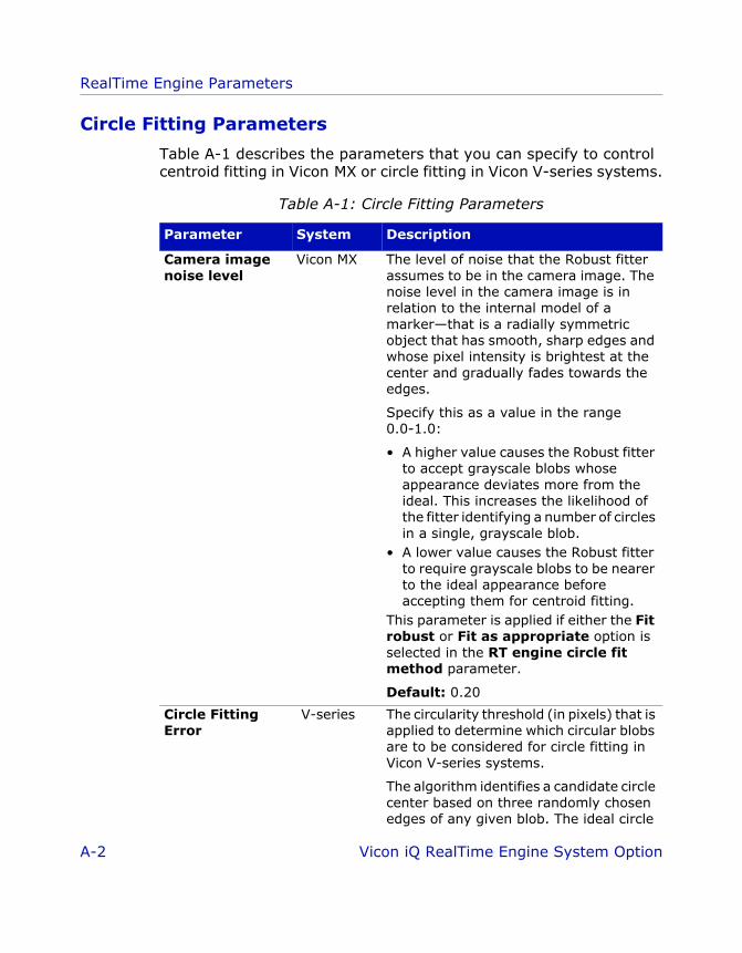
RealTime Engine Parameters
RTE_iQ_RTEparams.fm Page 2 Wednesday, June 22, 2005 2:54 PM
Circle Fitting Parameters
Table A-1 describes the parameters that you can specify to control centroid fitting in Vicon MX or circle fitting in Vicon V-series systems.
Table A-1: Circle Fitting Parameters
Parameter System Description
Camera image noise level
Vicon MX The level of noise that the Robust fitter assumes to be in the camera image. The noise level in the camera image is in relation to the internal model of a marker—that is a radially symmetric object that has smooth, sharp edges and whose pixel intensity is brightest at the center and gradually fades towards the edges.
Specify this as a value in the range 0.0-1.0:
• A higher value causes the Robust fitter to accept grayscale blobs whose appearance deviates more from the ideal. This increases the likelihood of the fitter identifying a number of circles in a single, grayscale blob.
• A lower value causes the Robust fitter to require grayscale blobs to be nearer to the ideal appearance before accepting them for centroid fitting.
This parameter is applied if either the Fit robust or Fit as appropriate option is selected in the RT engine circle fit method parameter.
Default: 0.20
Circle Fitting Error
V-series The circularity threshold (in pixels) that is applied to determine which circular blobs are to be considered for circle fitting in Vicon V-series systems.
The algorithm identifies a candidate circle center based on three randomly chosen edges of any given blob. The ideal circle
A-2 Vicon iQ RealTime Engine System Option

RealTime Engine Parameters
RTE_iQ_RTEparams.fm Page 3 Wednesday, June 22, 2005 2:54 PM
Circle Fitting Error (cont.)
given the proposed center and its radius is then evaluated against the remaining edges in the blob. If the actual edge is within the ideal edge, plus or minus the value specified in this parameter, the edge in question is assigned to the circle. When a high enough proportion of edges (as specified in the Minimum Circle Fitting Quality parameter) in any given blob has been assigned to a circle, the center of the circle is calculated using all the assigned edges.
Default: 1.3
Enable Grayscale Fitter
Vicon MX Enables or disables the RealTime Engine’s grayscale centroid fitter in Vicon MX.
Also see the RT engine circle fit method parameter.
Default: Enabled
Fast circle fit threshold
Vicon MX The circularity threshold that the Fast fitter in Vicon MX applies to resolve malformed or merged markers. Grayscale blobs with a circularity equal to or greater than this value are considered well-formed circular images for which the fitter generates centroids.
Specify this threshold as a value in the range of 0.0-1.0:
• 0.0 causes the Fast fitter to accept all grayscale blobs regardless of circularity
• 1.0 causes the Fast fitter to accept only grayscale blobs with perfect circularity.
This threshold is applied if either the Fit fast or the Fit as appropriate option is specified in the RT engine circle fit method parameter.
Default: 0.40
Table A-1: Circle Fitting Parameters
Parameter System Description
Vicon iQ RealTime Engine System Option A-3

RealTime Engine Parameters
RTE_iQ_RTEparams.fm Page 4 Wednesday, June 22, 2005 2:54 PM
Maximum circle diameter
Vicon MX and V-series
The maximum diameter (in pixels) of a grayscale blob that is to be considered for centroid fitting in Vicon MX. The maximum height (in scan lines) of a circular blob that is to be considered for circle fitting in Vicon V-series systems. Grayscale/circular blobs larger than this are discarded. This is useful for filtering out unwanted noise such as reflections from body parts that are too close to the cameras.
Specify this diameter as a value in the range of 0-100 pixels/scan lines:
• A lower value results in the fitter attempting to resolve fewer grayscale/circular blobs.
• A higher value results in the fitter attempting to resolve more grayscale/circular blobs.
For example, the maximum value of 100 causes the fitter to attempt to resolve most grayscale blobs.
Also see the Minimum circle diameter parameter.
Default: 100
Minimum circle diameter
Vicon MX and V-series
The minimum diameter (in pixels) of a grayscale blob that is to be considered for centroid fitting in Vicon MX. The minimum height (in scan lines) of a circular blob that is to be considered for circle fitting in Vicon V-series systems. Grayscale/circular blobs smaller than this are discarded.
Specify this diameter as a value in the range of 0-100 pixels/scan lines:
• A lower value causes the fitter to attempt to resolve more grayscale/
Table A-1: Circle Fitting Parameters
Parameter System Description
A-4 Vicon iQ RealTime Engine System Option

RealTime Engine Parameters
RTE_iQ_RTEparams.fm Page 5 Wednesday, June 22, 2005 2:54 PM
Minimum circle diameter (cont.)
circular blobs.
For example, the minimum value of 0 (zero) causes the fitter to attempt to resolve any and all blobs.
• A higher value causes the fitter to attempt to resolve fewer grayscale/circular blobs.
Also see the Maximum circle diameter parameter.
Default: 0
Minimum Circle Fitting Quality
V-series The proportion of edges from a circular blob that must be allocated to a candidate circle center before the circle fitting algorithm considers it to be a valid circle center. For example, the default 0.5 indicates that the candidate contains half the edges expected for its radius. If the proportion falls below this threshold, the algorithm discards the candidate center and chooses three new edges at random to generate a new circle candidate for that circular blob.
Also see the Circle Fitting Error parameter.
Default: 0.5
Robust circle fit threshold
Vicon MX The circularity threshold that the Robust fitter in Vicon MX applies to resolve malformed or merged markers. Grayscale blobs with a circularity equal to or greater than this value are considered well-formed circular images for which the fitter generates centroids.
Specify this threshold as a value in the range of 0.0-1.0:
• 0.0 causes the Robust fitter to accept all grayscale blobs regardless of
Table A-1: Circle Fitting Parameters
Parameter System Description
Vicon iQ RealTime Engine System Option A-5
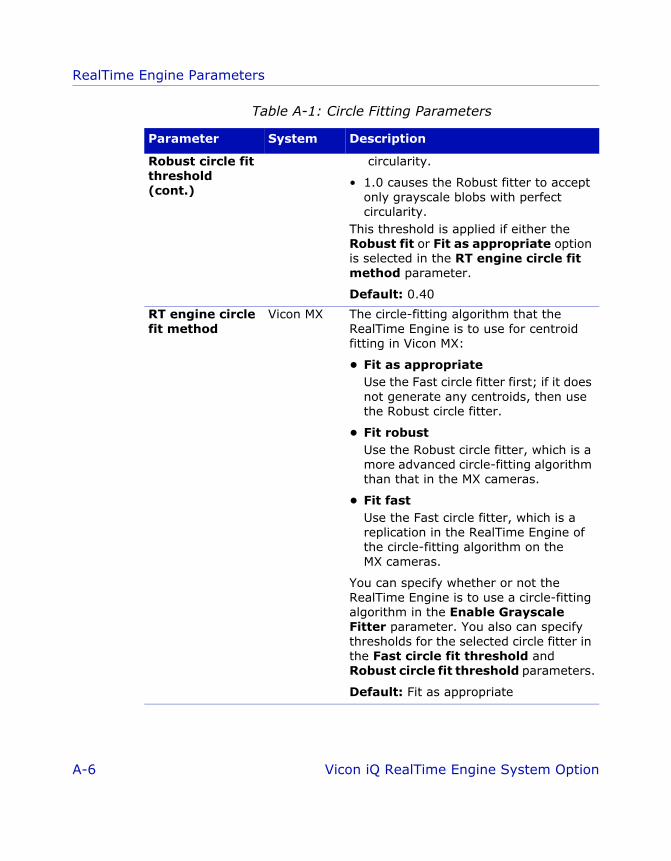
RealTime Engine Parameters
RTE_iQ_RTEparams.fm Page 6 Wednesday, June 22, 2005 2:54 PM
Robust circle fit threshold (cont.)
circularity.
• 1.0 causes the Robust fitter to accept only grayscale blobs with perfect circularity.
This threshold is applied if either the Robust fit or Fit as appropriate option is selected in the RT engine circle fit method parameter.
Default: 0.40
RT engine circle fit method
Vicon MX The circle-fitting algorithm that the RealTime Engine is to use for centroid fitting in Vicon MX:
• Fit as appropriateUse the Fast circle fitter first; if it does not generate any centroids, then use the Robust circle fitter.
• Fit robustUse the Robust circle fitter, which is a more advanced circle-fitting algorithm than that in the MX cameras.
• Fit fastUse the Fast circle fitter, which is a replication in the RealTime Engine of the circle-fitting algorithm on the MX cameras.
You can specify whether or not the RealTime Engine is to use a circle-fitting algorithm in the Enable Grayscale Fitter parameter. You also can specify thresholds for the selected circle fitter in the Fast circle fit threshold and Robust circle fit threshold parameters.
Default: Fit as appropriate
Table A-1: Circle Fitting Parameters
Parameter System Description
A-6 Vicon iQ RealTime Engine System Option

RealTime Engine Parameters
RTE_iQ_RTEparams.fm Page 7 Wednesday, June 22, 2005 2:54 PM
Kinematic Fitting and Filtering Parameters
Table A-2 describes the parameters that you can specify to control kinematic fitting and filtering.
The values you can select from drop-down lists for some parameters may differ between different Vicon application software, although the functionality of the parameter is identical. Such differences are indicated with a forward slash (e.g. value-x/value-y).
Table A-2: Kinematic Fitting and Filtering Parameters
Parameter System Description
Enable/disable kinematic fit
[Workstation only]
Vicon MX and V-series
Toggles kinematic fitting on or off in Workstation. The kinematic fitting algorithm positions the segments in the kinematic model displayed in the 3D Workspace so that markers on the model fit to the labeled trajectories.
Also see the Maximum Kinematic fit iterations parameter.
Default: Enabled
Kinematic filter prediction order
Vicon MX and V-series
The RealTime Engine predictor uses the Kalman filter in its kinematic trajectory motion model to predict the movement of markers attached to a skeleton or a rigid body. This parameter specifies which Kalman filter predictor equation the RealTime Engine trajectory predictor is to apply to the kinematically fitted results:
• 0/Filter OffNo Kalman filter is applied.
• 1/Constant PositionThe Kalman filter uses a constant position filtering model.
This setting is appropriate if steady positional data is required. For example, if you are tracking an interaction object that is used to identify positional data (such as
Vicon iQ RealTime Engine System Option A-7

RealTime Engine Parameters
RTE_iQ_RTEparams.fm Page 8 Wednesday, June 22, 2005 2:54 PM
Kinematic filter prediction order (cont.)
Vicon MX and V-series
pointing at virtual objects), this filtering method ensures that the pointer will be the steadiest. The trade-off is that the filter will, to a certain extent (determined by the other Kinematic prediction parameters described in this table), resist movement. This means that the virtual object will, to a greater or lesser extent, lag behind the real object in the virtual world.
• 2/Constant VelocityThe Kalman filter uses a constant velocity filtering model.
This setting is appropriate if smooth movement is more important than steady positioning. This filtering method ensures that the virtual object does not lag behind the real one when the object is moving, but it also means that the virtual object is less steady when it is stationary.
If you are using kinematic smoothing, as well as specifying a value for a Kalman filter in this Kinematic filter prediction order, you must also specify a value greater than or equal to 5 in the Maximum Kinematic fit iterations parameter.
Default: 0/Filter Off
Kinematic filter rotational prediction factor
Vicon MX and V-series
The level of kinematic filtering to be applied to the rotation of the subject being tracked.
Specify this factor as value in the range of 0.01-1 radians per second (rad/s):
• A lower value applies more filtering to the subject’s rotation.
Table A-2: Kinematic Fitting and Filtering Parameters
Parameter System Description
A-8 Vicon iQ RealTime Engine System Option

RealTime Engine Parameters
RTE_iQ_RTEparams.fm Page 9 Wednesday, June 22, 2005 2:54 PM
Kinematic filter rotational prediction factor (cont.)
If the subject will experience rapid rotations, a low value means that the tracked object will lag behind. In other words, it will prevent the virtual version of the tracked object from being rotated very quickly.
A value of around 0.3 rad/s applies a medium amount of filtering.
• A higher value applies less filtering to the subject’s rotation. The maximum value of 1.0 rad/s provides a very moderate amount of filtering.
Also see the Kinematic filter prediction order and the Kinematic filter translational prediction factor parameters.
Default: 0.10
Kinematic filter translational prediction factor
Vicon MX and V-series
The level of kinematic filtering to be applied to the translation of the subject being tracked.
Specify this factor as value in the range of 1-100 millimeters per second:
• A lower value applies more filtering to the subject’s translation. For example, a value of 30 mm/s means that the virtual object will resist rapid translational movements. If the object moves fast, too low a value will result in its virtual representation lagging behind.
• A higher value applies less filtering to the subject’s translation. However, too high a value will fail to filter out some of the noise. The maximum value of 100 mm/s provides a moderate amount of filtering.
Table A-2: Kinematic Fitting and Filtering Parameters
Parameter System Description
Vicon iQ RealTime Engine System Option A-9
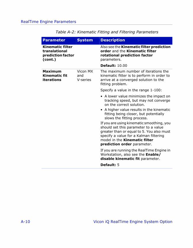
RealTime Engine Parameters
RTE_iQ_RTEparams.fm Page 10 Wednesday, June 22, 2005 2:54 PM
Kinematic filter translational prediction factor (cont.)
Also see the Kinematic filter prediction order and the Kinematic filter rotational prediction factor parameters.
Default: 10.00
Maximum Kinematic fit iterations
Vicon MX and V-series
The maximum number of iterations the kinematic fitter is to perform in order to arrive at a converged solution to the fitting problem.
Specify a value in the range 1-100:
• A lower value minimizes the impact on tracking speed, but may not converge on the correct solution.
• A higher value results in the kinematic fitting being closer, but potentially slows the fitting process.
If you are using kinematic smoothing, you should set this parameter to a value greater than or equal to 5. You also must specify a value for a Kalman filtering model in the Kinematic filter prediction order parameter.
If you are running the RealTime Engine in Workstation, also see the Enable/disable kinematic fit parameter.
Default: 5
Table A-2: Kinematic Fitting and Filtering Parameters
Parameter System Description
A-10 Vicon iQ RealTime Engine System Option

RealTime Engine Parameters
RTE_iQ_RTEparams.fm Page 11 Wednesday, June 22, 2005 2:54 PM
Offline Data Streaming Parameters
Table A-3 describes the parameters that you can specify to control the type of offline data the RealTime Engine streams.
Table A-3: Offline Data Streaming Parameters
Parameter System Description
CP file name Vicon MX and V-series
The full path and file name of the camera calibration (.cp) file corresponding to the raw data file:
• The .tvd file specified in the TVD file name parameter for Vicon V-series systems
• The .x2d file specified in the X2D file name parameter for Vicon MX
Default: None
TVD file name V-series The full path and file name of the .tvd file corresponding to the .cp file specified in CP filename parameter.
The .tvd file contains raw data previously captured in Vicon V-series systems that is to be streamed through the RealTime Engine. You can control the rate at which data is streamed from this file using the Skip rate parameter.
Default: None
X2D file name Vicon MX and V-series
The full path and file name of the .x2d file corresponding to the .cp file specified in CP filename parameter.
The .x2d file contains raw data previously captured in Vicon MX that is to be streamed through the RealTime Engine. You can control the rate at which data is streamed from this file using the Skip rate parameter.
Default: None
Vicon iQ RealTime Engine System Option A-11
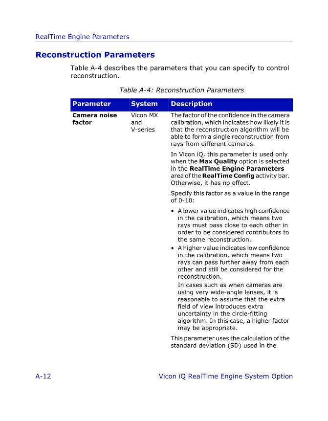
RealTime Engine Parameters
RTE_iQ_RTEparams.fm Page 12 Wednesday, June 22, 2005 2:54 PM
Reconstruction Parameters
Table A-4 describes the parameters that you can specify to control reconstruction.
Table A-4: Reconstruction Parameters
Parameter System Description
Camera noise factor
Vicon MX and V-series
The factor of the confidence in the camera calibration, which indicates how likely it is that the reconstruction algorithm will be able to form a single reconstruction from rays from different cameras.
In Vicon iQ, this parameter is used only when the Max Quality option is selected in the RealTime Engine Parameters area of the RealTime Config activity bar. Otherwise, it has no effect.
Specify this factor as a value in the range of 0-10:
• A lower value indicates high confidence in the calibration, which means two rays must pass close to each other in order to be considered contributors to the same reconstruction.
• A higher value indicates low confidence in the calibration, which means two rays can pass further away from each other and still be considered for the reconstruction. In cases such as when cameras are using very wide-angle lenses, it is reasonable to assume that the extra field of view introduces extra uncertainty in the circle-fitting algorithm. In this case, a higher factor may be appropriate.
This parameter uses the calculation of the standard deviation (SD) used in the
A-12 Vicon iQ RealTime Engine System Option
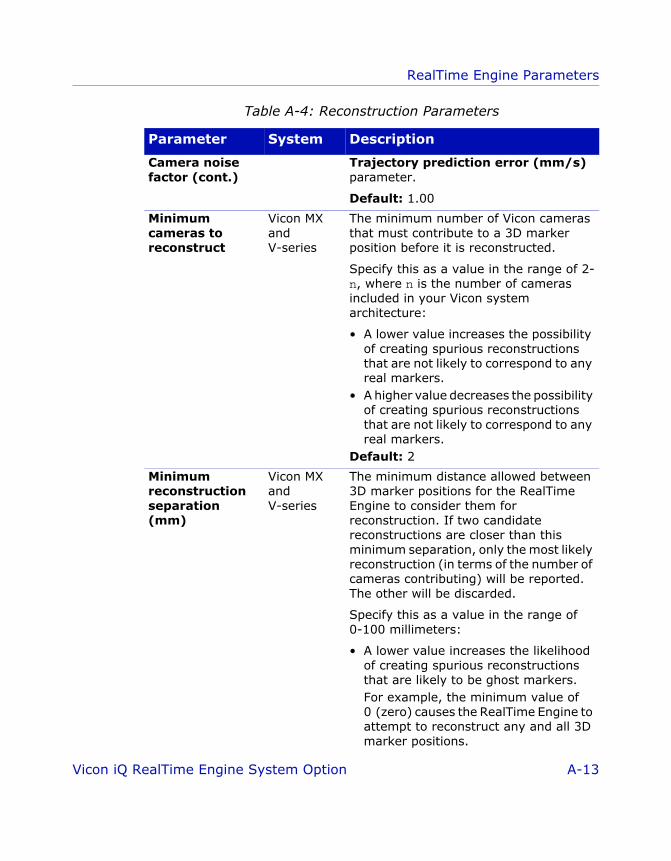
RealTime Engine Parameters
RTE_iQ_RTEparams.fm Page 13 Wednesday, June 22, 2005 2:54 PM
Camera noise factor (cont.)
Trajectory prediction error (mm/s) parameter.
Default: 1.00
Minimum cameras to reconstruct
Vicon MX and V-series
The minimum number of Vicon cameras that must contribute to a 3D marker position before it is reconstructed.
Specify this as a value in the range of 2-n, where n is the number of cameras included in your Vicon system architecture:
• A lower value increases the possibility of creating spurious reconstructions that are not likely to correspond to any real markers.
• A higher value decreases the possibility of creating spurious reconstructions that are not likely to correspond to any real markers.
Default: 2
Minimum reconstruction separation (mm)
Vicon MX and V-series
The minimum distance allowed between 3D marker positions for the RealTime Engine to consider them for reconstruction. If two candidate reconstructions are closer than this minimum separation, only the most likely reconstruction (in terms of the number of cameras contributing) will be reported. The other will be discarded.
Specify this as a value in the range of 0-100 millimeters:
• A lower value increases the likelihood of creating spurious reconstructions that are likely to be ghost markers. For example, the minimum value of 0 (zero) causes the RealTime Engine to attempt to reconstruct any and all 3D marker positions.
Table A-4: Reconstruction Parameters
Parameter System Description
Vicon iQ RealTime Engine System Option A-13

RealTime Engine Parameters
RTE_iQ_RTEparams.fm Page 14 Wednesday, June 22, 2005 2:54 PM
Minimum reconstruction separation (cont.)
• A higher value decreases the likelihood of creating spurious reconstructions, but increases the possibility that some real markers will not be reconstructed.
Default: 0.00
Ray intersect SDs
Vicon MX and V-series
The maximum distance allowed between two rays for the reconstruction algorithm to assume they have contributed to the same marker reconstruction.
In Vicon iQ, this parameter is used only when the Max Speed option is selected in the RealTime Engine Parameters area of the RealTime Config activity bar. Otherwise, it has no effect.
Specify this as a value in the range 0-20:
• A lower value indicates high confidence in the calibration, which means two rays must pass close to each other in order to be considered for the reconstruction.
• A higher value indicates low confidence in the calibration, which means two rays can pass further way from each other and still be considered for the reconstruction.In cases such as when cameras are using very wide-angle lenses, it is reasonable to assume that the extra field of view introduces extra uncertainty in the circle-fitting algorithm. In this case, a higher factor may be appropriate.
This parameter uses the calculation of the standard deviation (SD) used in the Trajectory prediction error (mm/s) parameter.
Default: 4
Table A-4: Reconstruction Parameters
Parameter System Description
A-14 Vicon iQ RealTime Engine System Option

RealTime Engine Parameters
RTE_iQ_RTEparams.fm Page 15 Wednesday, June 22, 2005 2:54 PM
Ray noise factor Vicon MX and V-series
The scale factor describing the confidence in the circle fitting performed.
In Vicon iQ, this parameter is used only when the Max Quality option is selected in the RealTime Engine Parameters area of the RealTime Config activity bar. Otherwise, it has no effect.
Specify this factor as a value in the range of 0-10:
• A lower value indicates high confidence in the circles, which means two rays must pass close to each other in order to be considered contributors to the same reconstruction.
• A higher value indicates low confidence, which means two rays can pass further away from each other and still be considered contributors to the same reconstruction.
The final circle uncertainty used in reconstruction is the circle fitting uncertainty calculated by the RT engine circle fit method parameter multiplied by the value in this Ray Noise Factor parameter plus the camera calibration uncertainty from the calibration file multiplied by the value in the Camera noise factor parameter.
Default: 1.00
Table A-4: Reconstruction Parameters
Parameter System Description
Vicon iQ RealTime Engine System Option A-15

RealTime Engine Parameters
RTE_iQ_RTEparams.fm Page 16 Wednesday, June 22, 2005 2:54 PM
Trajectory Fitting Parameters
Table A-5 describes the parameters that you can specify to control trajectory fitting.
Table A-5: Trajectory Fitting Parameters
Parameter System Description
Minimum cameras to start trajectory
Vicon MX and V-series
The minimum number of Vicon cameras that must contribute to a trajectory before it is reconstructed.
Specify this as a value in the range of 2-n, where n is the number of cameras included in your Vicon system architecture:
• A lower value results in more reconstructions being incorporated into trajectories, however, it may increase the chance of spurious trajectories being generated.
• A higher value makes it less likely that the trajectory fitter will generate spurious trajectories, however, it may result in fewer trajectories being generated.
The value of this parameter typically is slightly larger than that for the Minimum cameras to reconstruct parameter.
Default: 3
Predictor order Vicon MX and V-series
The method that the RealTime Engine trajectory predictor is to use when trying to predict the movement of a given marker reconstruction from the current to the next sample:
• Constant PositionThis method assumes that the marker does not move.
The trajectory predictor considers only the current sample, so it expects that in the next sample the marker will be
A-16 Vicon iQ RealTime Engine System Option

RealTime Engine Parameters
RTE_iQ_RTEparams.fm Page 17 Wednesday, June 22, 2005 2:54 PM
Predictor order (cont.)
lying in exactly the same position as the current sample.
This option is typically used for an object that is still or mostly stationary.
• Constant VelocityThis method assumes that the marker moves exactly the same distance in exactly the same direction.
The trajectory predictor considers two samples (the current and the previous position), so it expects that in the next sample the marker will have followed a straight-line path.
This option is typically used for an object or subject that moves very steadily and smoothly.
• Constant AccelerationThis method assumes that the marker moves in the same direction and at the same acceleration.
The trajectory predictor considers three samples (the current and the two previous positions), so it expects that in the next sample the marker will have followed a parabolic path.
This option is typically used for a subject that moves less predictably. It is the most suitable option for tracking the movement of human subjects.
Also see the Trajectory prediction error (mm/s) parameter.
Default: Constant Acceleration
Table A-5: Trajectory Fitting Parameters
Parameter System Description
Vicon iQ RealTime Engine System Option A-17

RealTime Engine Parameters
RTE_iQ_RTEparams.fm Page 18 Wednesday, June 22, 2005 2:54 PM
Skip rate Vicon MX and V-series
The processing rate for streaming real-time data from the offline .x2d file specified in the X2D file name parameter (for Vicon MX) or the .tvd file specified in the TVD file name parameter (for Vicon V-series systems):
• 0/Emulate RealtimeThe RealTime Engine treats the X2D/TVD file as if it were a real-time data source to emulate the performance that would be achieved if running live.
• 1/Process AllThe RealTime Engine processes every frame from the .x2d/.tvd file as fast as it can. The .x2d/.tvd file data is processed as if it was captured in real time, that is, the camera data is fed to the RealTime Engine at the same rate as if it were being streamed in real time from the cameras.
• 2/Process every 2ndThe RealTime Engine processes every second frame of the .x2d/.tvd file. This could mean that the processing happens either slower or faster than it would have in real time, depending on how much data the .x2d/.tvd file contains and on the capacity of the processing hardware.
• 3/Process every 3rdThe RealTime Engine processes every third frame of the .x2d/.tvd file.
Table A-5: Trajectory Fitting Parameters
Parameter System Description
A-18 Vicon iQ RealTime Engine System Option

RealTime Engine Parameters
RTE_iQ_RTEparams.fm Page 19 Wednesday, June 22, 2005 2:54 PM
Skip rate (cont.) • 4/Process every 4thThe RealTime Engine processes every fourth frame of the .x2d/.tvd file.
In Vicon iQ, you can continue to specify every nth frame, where n is a positive number.
Default: 1/Process All
Trajectory prediction error (mm/s)
Vicon MX and V-series
The accuracy with which marker trajectories can be predicted over time. This algorithm attempts to predict the locations of all markers when a new frame comes in. As markers move in unpredictable ways, this algorithm is used to establish a radius of uncertainty around the prediction. If the measured marker falls within this radius, this algorithm concludes that the measured marker is the same as the predicted one.
The purpose of using predictions in reconstructions is chiefly to aid in situations where there are conflicts in ray assignment—that is, a given ray from one camera intersects two or more rays from another camera within the limit set by the Ray noise factor and Camera noise factor parameters. In this situation, knowledge of where the marker is most likely to be, based on historical information, is very likely to resolve the conflict.
The predictions also are used to aid the labeler. In this case, the prediction and its radius of uncertainty provide the labeler with a certain number of candidate reconstructions for a given label. If the radius of uncertainty is such that only one marker falls within this radius, the task is
Table A-5: Trajectory Fitting Parameters
Parameter System Description
Vicon iQ RealTime Engine System Option A-19

RealTime Engine Parameters
RTE_iQ_RTEparams.fm Page 20 Wednesday, June 22, 2005 2:54 PM
Trajectory prediction error (cont.)
simple, but if two or more markers fall within the radius, the task becomes more complicated.
Specify this as a value in the range of 10-500 millimeters per second:
• A lower value results in a more accurate prediction, but increases the possibility of a broken trajectory if a marker moves too fast. A lower value, such as 35 mm/s, is appropriate if marker movement is generally quite slow.However, if the value is too low, the radius of uncertainty around a given marker is small, so a fast-moving marker will have a higher likelihood of falling outside this radius. If this happens, the benefits of the prediction are lost, and ray conflicts may not be solvable, which can result in spurious marker reconstructions, mislabeled markers, or slow labeling.
• A higher value results in a less accurate prediction, but decreases the possibility of a broken trajectory if a marker moves too fast. A higher value is appropriate if the application is tracking a lot of fast movement.However, if the value is too high, the likelihood of more than one marker falling within the radius of uncertainty increases, so the trajectory labeler may find it more difficult to determine which marker corresponds to the tracked one. This can cause labeling problems.
Also see the Predictor order parameter.
Default: 70.00
Table A-5: Trajectory Fitting Parameters
Parameter System Description
A-20 Vicon iQ RealTime Engine System Option
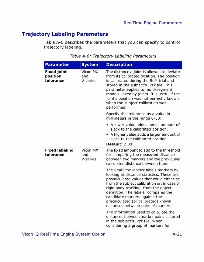
RealTime Engine Parameters
RTE_iQ_RTEparams.fm Page 21 Wednesday, June 22, 2005 2:54 PM
Trajectory Labeling Parameters
Table A-6 describes the parameters that you can specify to control trajectory labeling.
Table A-6: Trajectory Labeling Parameters
Parameter System Description
Fixed joint position tolerance
Vicon MX and V-series
The distance a joint is allowed to deviate from its calibrated position. The position is calibrated during the RoM trial and stored in the subject's .vsk file. This parameter applies to multi-segment models linked by joints. It is useful if the joint’s position was not perfectly known when the subject calibration was performed.
Specify this tolerance as a value in millimeters in the range 0-50:
• A lower value adds a small amount of slack to the calibrated position.
• A higher value adds a larger amount of slack to the calibrated position.
Default: 2.00
Fixed labeling tolerance
Vicon MX and V-series
The fixed amount to add to the threshold for comparing the measured distance between two markers and the previously calculated distance between them.
The RealTime labeler labels markers by looking at distance statistics. These are precalculated values that could either be from the subject calibration or, in case of rigid body tracking, from the object definition. The labeler compares the candidate markers against the precalculated (or calibrated) known distances between pairs of markers.
The information used to calculate the distances between marker pairs is stored in the subject's .vsk file. When considering a group of markers for
Vicon iQ RealTime Engine System Option A-21

RealTime Engine Parameters
RTE_iQ_RTEparams.fm Page 22 Wednesday, June 22, 2005 2:54 PM
Fixed labeling tolerance (cont.)
labeling, the labeler calculates the distances from each marker to all the other ones. It then uses an algorithm to try to assign labels based on the similarity of these measured distances to the calibrated ones. A distance between two markers is deemed to be similar enough to a calibrated distance when the measured distance falls within the calibrated distance plus/minus a labeling threshold.
This fixed amount is in addition to the percentage specified in the Proportional labeling tolerance parameter. Thus, the combined labeling tolerance is this fixed labeling tolerance plus the proportional labeling tolerance multiplied by the original calibrated marker distance variation (from the calibration file).
Specify this tolerance as a value in millimeters in the range 0-50:
• A lower value means that distance between markers is not allowed to exceed the calibrated distance by much.
• A higher value means that distance between markers can exceed the calibrated distance more significantly.
Default: 2.00
Incremental labeling decisiveness
Vicon MX and V-series
The amount by which the labeler multiplies the starting value specified in the Initial labeling decisiveness parameter for each subsequent iteration of the labeling process.
Specify this as a value in the range 0.1-2.0:
• A lower value results in a slower
Table A-6: Trajectory Labeling Parameters
Parameter System Description
A-22 Vicon iQ RealTime Engine System Option

RealTime Engine Parameters
RTE_iQ_RTEparams.fm Page 23 Wednesday, June 22, 2005 2:54 PM
Incremental labeling decisiveness (cont.)
labeling process, but reduces the possibility of labeling errors.
• A higher value results in a faster labeling process, but increases the possibility of labeling errors.
This parameter and the Initial labeling decisiveness parameter work together. In general you are recommended to set both values either:
• Low to maximize the quality of the labeling process.
• High to maximize the speed of the labeling process.
Default: 1.20
Initial labeling decisiveness
Vicon MX and V-series
The value at which the labeler starts the labeling process. Labeling is an iterative process, during which the labeler continuously improves its assessment of which markers correspond to which reconstructions until it is confident in its result.
Specify this as a value in the range 0.1-1.5:
• A lower value results in a slower labeling process, but reduces the possibility of labeling errors.
• A higher value results in a faster labeling process, but increases the possibility of labeling errors.
For each subsequent iteration, the labeler multiplies the starting value specified in this Initial labeling decisiveness parameter by the value specified for the Incremental labeling decisiveness parameter.
The settings of the two parameters work together. In general you are
Table A-6: Trajectory Labeling Parameters
Parameter System Description
Vicon iQ RealTime Engine System Option A-23

RealTime Engine Parameters
RTE_iQ_RTEparams.fm Page 24 Wednesday, June 22, 2005 2:54 PM
Initial labeling decisiveness (cont.)
recommended to set both values either:
• Low to maximize the quality of the labeling process.
• High to maximize the speed of the labeling process.
Default: 0.40
Labeling perseverance
Vicon MX and V-series
The level of perseverance the labeler uses when attempting to label reconstructed markers that did not appear in the previous frame.
Select one of the following values from the list displayed if the Macro button is enabled and pressed in:
• Extremely low (1e-4)• Very low (1e-6)• Low (1e-80)• Medium (1e-100)• High (1e-12)• Very high (1e-14)• Extremely high (1e-16)Alternatively, click the Macro button so that it is not pressed in and then enter a specific value in the displayed entry field.
At lower values, the labeler labels only the best-fit markers and then leaves remaining markers unlabeled.
At higher values, the labeler perseveres with its attempts to label all markers in a marker cloud. This results in the labeler labeling everything, but increases the possibility of it assigning incorrect labels to some markers.
Also see the Relabeling perseverance parameter.
Default: Medium
Table A-6: Trajectory Labeling Parameters
Parameter System Description
A-24 Vicon iQ RealTime Engine System Option

RealTime Engine Parameters
RTE_iQ_RTEparams.fm Page 25 Wednesday, June 22, 2005 2:54 PM
Marker statistics threshold
Vicon MX and V-series
The threshold at which the labeler stops considering labeling hypotheses and determines that there is no likelihood of two markers being considered a label pair.
Select one of the following values from the list displayed if the Macro button is enabled and pressed in:
• Extremely low (0)• Very low [(1e-30)• Low (1e-20)• Medium (1e-10)• High (1e-6)• Very high (1e-4)• Extremely high (1e-2)Alternatively, click the Macro button so that it is not pressed in and then enter a specific value in the displayed entry field.
Lower values cause the labeler to discard more labeling hypotheses because the likelihood falls below the threshold. For example, setting this value to Extremely low essentially means that the threshold is zero. This results in a faster labeling process, but increases the possibility of labeling errors.
Higher values cause the labeler to discard fewer (even very unlikely) hypotheses. This results in a slower labeling process as the algorithm is slower and consumes more memory since it has to keep track of more hypotheses. However, it reduces the possibility of labeling errors.
Default: Low (1e-20)
Table A-6: Trajectory Labeling Parameters
Parameter System Description
Vicon iQ RealTime Engine System Option A-25
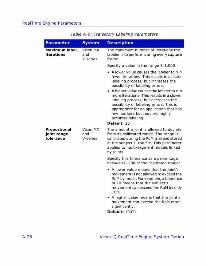
RealTime Engine Parameters
RTE_iQ_RTEparams.fm Page 26 Wednesday, June 22, 2005 2:54 PM
Maximum label iterations
Vicon MX and V-series
The maximum number of iterations the labeler is to perform during every capture frame.
Specify a value in the range 3-1,000:
• A lower value causes the labeler to run fewer iterations. This results in a faster labeling process, but increases the possibility of labeling errors.
• A higher value causes the labeler to run more iterations. This results in a slower labeling process, but decreases the possibility of labeling errors. This is appropriate for an application that has few markers but requires highly accurate labeling.
Default: 20
Proportional joint range tolerance
Vicon MX and V-series
The amount a joint is allowed to deviate from its calibrated range. The range is calibrated during the RoM trial and stored in the subject's .vsk file. This parameter applies to multi-segment models linked by joints.
Specify this tolerance as a percentage between 0-200 of the calibrated range:
• A lower value means that the joint’s movement is not allowed to exceed the RoM by much. For example, a tolerance of 10 means that the subject’s movement can exceed the RoM by only 10%.
• A higher value means that the joint’s movement can exceed the RoM more significantly.
Default: 10.00
Table A-6: Trajectory Labeling Parameters
Parameter System Description
A-26 Vicon iQ RealTime Engine System Option
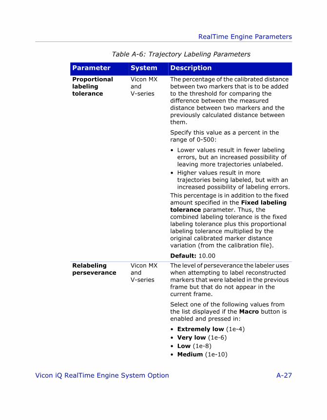
RealTime Engine Parameters
RTE_iQ_RTEparams.fm Page 27 Wednesday, June 22, 2005 2:54 PM
Proportional labeling tolerance
Vicon MX and V-series
The percentage of the calibrated distance between two markers that is to be added to the threshold for comparing the difference between the measured distance between two markers and the previously calculated distance between them.
Specify this value as a percent in the range of 0-500:
• Lower values result in fewer labeling errors, but an increased possibility of leaving more trajectories unlabeled.
• Higher values result in more trajectories being labeled, but with an increased possibility of labeling errors.
This percentage is in addition to the fixed amount specified in the Fixed labeling tolerance parameter. Thus, the combined labeling tolerance is the fixed labeling tolerance plus this proportional labeling tolerance multiplied by the original calibrated marker distance variation (from the calibration file).
Default: 10.00
Relabeling perseverance
Vicon MX and V-series
The level of perseverance the labeler uses when attempting to label reconstructed markers that were labeled in the previous frame but that do not appear in the current frame.
Select one of the following values from the list displayed if the Macro button is enabled and pressed in:
• Extremely low (1e-4)• Very low (1e-6)• Low (1e-8)• Medium (1e-10)
Table A-6: Trajectory Labeling Parameters
Parameter System Description
Vicon iQ RealTime Engine System Option A-27
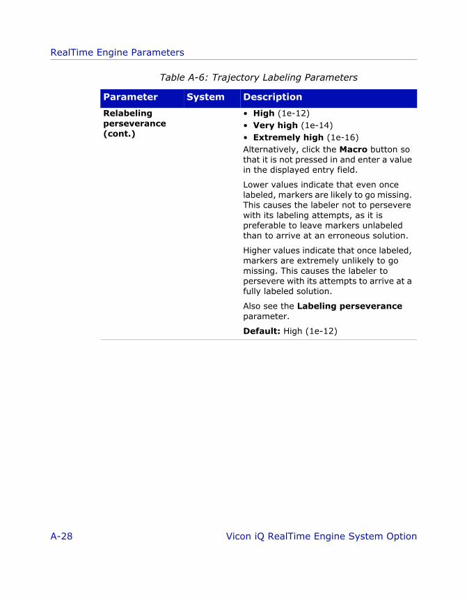
RealTime Engine Parameters
RTE_iQ_RTEparams.fm Page 28 Wednesday, June 22, 2005 2:54 PM
Relabeling perseverance (cont.)
• High (1e-12)• Very high (1e-14)• Extremely high (1e-16)Alternatively, click the Macro button so that it is not pressed in and enter a value in the displayed entry field.
Lower values indicate that even once labeled, markers are likely to go missing. This causes the labeler not to persevere with its labeling attempts, as it is preferable to leave markers unlabeled than to arrive at an erroneous solution.
Higher values indicate that once labeled, markers are extremely unlikely to go missing. This causes the labeler to persevere with its attempts to arrive at a fully labeled solution.
Also see the Labeling perseverance parameter.
Default: High (1e-12)
Table A-6: Trajectory Labeling Parameters
Parameter System Description
A-28 Vicon iQ RealTime Engine System Option
ViconiQ_Option_RTE.book Page 1 Tuesday, June 21, 2005 2:53 PM
BBV i con Ske leton Template ( .vst) F i les
The Vicon Skeleton Template (.vst) file is used by Vicon software to describe relationships between Vicon markers and a subject’s segments and joints. The format of this file enables you to describe any sort of kinematic model from a single, rigid object to a complex advanced model of a human being. A .vst file for a basic kinematic model of a human being describes the generic hierarchy and geometry of a human skeleton. The .vst file for a musculoskeletal model can be extended to include normalized attachment data for muscles, ligaments, and wrap objects as well as models for muscle and ligament force.
A .vst file for use with the RealTime Engine consists of the following three main sections:
• Parameters: Contains the parameters used to describe variations in the subject proportions and marker placement
• Skeleton: Describes the skeletal hierarchy and geometry
• MarkerSet: Describes the markers that form part of the template and their position with respect to assigned segments. Segments are defined by their markers, not the other way around.
These three main sections must be present in every .vst file for use with the RealTime Engine, but the content of each section can vary according to specific requirements of the model you are creating. The .vst files for use with other Vicon application software may contain different sections. For details, see the documentation for that Vicon software.
Vicon iQ RealTime Engine System Option B-1

Vicon Skeleton Template (.vst) Files
ViconiQ_Option_RTE.book Page 2 Tuesday, June 21, 2005 2:53 PM
VST File Format
Vicon Skeleton Template (.vst) files are written in eXtensible Markup Language (.xml) file format. These .xml files are used to store structured information and to enclose or encapsulate information so that it can be passed between different computing systems. As in any .xml file, .vst file sections are delimited with start and end section tags, and subsections are nested beneath main sections to reflect their hierarchical relationship, for example:
<Parameters><Parameter NAME="HalfHipWidth" VALUE="90"/><Parameter NAME="BackHeight" VALUE="250"/><Parameter NAME="ClavicleHeight" VALUE="250"/><Parameter NAME="NeckHeight" VALUE="250"/>
</Parameters>
ImportantThe .vst file can be viewed in most Web browsers or standard text editors like any other .xml file. You may find it helpful to view one of the sample .vst files provided under the Models folder for your Vicon application software (by default, C:\Program Files\Vicon\Models) while you read this appendix describing the general format and content of a .vst file for the human body. This appendix assumes you have a basic understanding of the use and presentation of .xml files.
VST File Structure
The full structure of a .vst file for use with the RealTime Engine is outlined below. Details for the contents of each of the main sections of the file are provided in the following sections of this appendix.
<?xml version="1.0" encoding="UTF-8" standalone="yes"?><KinematicModelTemplate VERSION="1.0">
<Parameters><Parameter NAME=”” ATTRIBUTE="value"/>...
</Parameters>
<Skeleton><Segment NAME="" ATTRIBUTE="value">
B-2 Vicon iQ RealTime Engine System Option

Vicon Skeleton Template (.vst) Files
ViconiQ_Option_RTE.book Page 3 Tuesday, June 21, 2005 2:53 PM
<JointType ATTRIBUTE="value"/> <Segment ATTRIBUTE="value">
... </Segment>
</Segment>...
</Skeleton>
<MarkerSet NAME=""><Markers>
<Marker NAME="" ATTRIBUTE="value"/>...
</Markers>
<Sticks><Stick ATTRIBUTE="value"/>...
</Sticks></MarkerSet><ScalingGroups>
<Group/>...
</ScalingGroups></KinematicModelTemplate>
XML Header
The header <?xml version="1.0" encoding="UTF-8" standalone="no"?> is essential for the file to be recognized as .xml by Vicon applications and other .xml viewing packages. Do not edit this section.
VST File Attribute Syntax
Each option in a given section of a VST file consists of a keyword and one or more attribute="value" pairs. This is written in the following way in a .xml file:
<Keyword ATTRIBUTE="value"/>
Vicon iQ RealTime Engine System Option B-3

Vicon Skeleton Template (.vst) Files
ViconiQ_Option_RTE.book Page 4 Tuesday, June 21, 2005 2:53 PM
The Keyword identifies the element with which the Vicon application is to be concerned, the ATTRIBUTE is a characteristic of the specified keyword, and the value is the actual data that the Vicon application is to use. For most options, you must specify the value required for your specific implementation of the .vst file. To help you understand how to construct these definitions in your .vst file, when giving the syntax for a section, this appendix provides the Keyword and ATTRIBUTE words, followed by a description of the type of data you must supply for the value within the quotation marks for each ATTRIBUTE.
For example:
<Joint NAME="" POSITION=""/>
where:
A number of attributes take values based on the item's position in the local coordinate system. These are specified in the following format "x y z" where the x, y and z values are in local segment coordinates.
Where a keyword can take multiple ATTRIBUTE="value" pairs, the order in which you specify each pair is not significant.
Parameters Section
The <Parameters> section of a .vst file for a kinematic model contains a list of the parameters that are used to describe the geometry of the skeleton.
The start and end section tags for this section are:
<Parameters>...
</ Parameters>
NAME is a name that uniquely identifies the joint.
POSITION is the joint's position in the local coordinate system (specified as x y z).
B-4 Vicon iQ RealTime Engine System Option

Vicon Skeleton Template (.vst) Files
ViconiQ_Option_RTE.book Page 5 Tuesday, June 21, 2005 2:53 PM
Within this section, one or more individual <Parameter> definitions are included in the following format:
<Parameter NAME="" VALUE=""/>
where:
Parameters are provided to enable the real geometry of a model to be scaled to a specific subject. For example, a Thigh parameter might be used to represent the length of the femur and to scale the ltibia and rtibia segments. A LeftFemurLength parameter might be used to represent the length of the femur, to scale the LeftFemur segment, and to locate the LkneeAngles joint type in the <Skeleton> section of the .vst file. For specific examples, see the sample .vst files supplied with your Vicon application software.
Skeleton Section
The <Skeleton> section of a .vst file for a basic kinematic model contains information about the hierarchical connections between a set of segments. Each segment has a joint that connects it to its parent.
The start and end section tags for this section are:
<Skeleton>...
</Skeleton>
Within this section, one or more individual <Segment> definitions are included in the following format:
<Segment NAME="" BOUNDS="" ORIENTATION="" POSITION=""><JointType/>
</Segment>
NAME is the unique name of the parameter.
VALUE is the value of the parameter. Length units are specified in millimeters, and rotational units are specified in radians.
Vicon iQ RealTime Engine System Option B-5

Vicon Skeleton Template (.vst) Files
ViconiQ_Option_RTE.book Page 6 Tuesday, June 21, 2005 2:53 PM
where:
NAME is the name of the skeleton segment.
If you are streaming RealTime data through Workstation into Polygon, the names of segments in the .vst file must exactly match the names of mesh segments in the mesh (.obj) file. For example, a trial in which Plug-In Gait has been run contains the segments pelvis, lfemur, ltibia, etc. Look in the RT_PlugInGait_FullBody_COM.vst example file to confirm that the NAME attributes specified for the corresponding <Segment> parameters match the name of the mesh segments in the RT_PlugInGaitBones.obj file.
BOUNDS specifies the 3D bounding box for the segment to be displayed in the 3D Workspace View as a pair of vectors, each in x y z format.
The values for the first vector b1-b3 identify one corner and b4-b6 the opposite corner with respect to the segment's local coordinate system.
ORIENTATION specifies the orientation of the joint attaching the segment to its parent. This is expressed in the reference coordinate system of the parent segment. The orientation is specified as a helical vector. The direction of this vector gives the direction of the axis. The magnitude of this vector gives the amount of rotation around that axis in radians.
POSITION specifies the position of the segment's joint attaching it to its parent in the reference coordinate system of the parent segment.
B-6 Vicon iQ RealTime Engine System Option

Vicon Skeleton Template (.vst) Files
ViconiQ_Option_RTE.book Page 7 Tuesday, June 21, 2005 2:53 PM
JointType identifies the type of joint used between segments, one of:
JointDummy A fixed joint with 0 (zero) Degrees of Freedom (DOF), for example a joint that has been surgically pinned.
This joint type has no translational or rotational freedom.
JointFree A 6 DOF free joint.
This joint type has full translational as well a rotational freedom. It is typically used for the root segment to allow the root to move freely with respect to the global origin.
JointBall A 3 DOF ball-and-socket joint.
This joint type has full rotational (but not translational) freedom. The position of the child segment is defined from the position of the parent and joint, but its orientation can vary freely.
JointHardySpicer A 2 DOF "Hardy-spicer" (or universal) joint.
This joint type has two rotational degrees of freedom around two orthogonal axes. You must specify two vectors defining the directions of the two axes in the coordinate system of the parent segment around which the joint can rotate in the following format:
AXIS-PAIR="x y z x y z"
Vicon iQ RealTime Engine System Option B-7

Vicon Skeleton Template (.vst) Files
ViconiQ_Option_RTE.book Page 8 Tuesday, June 21, 2005 2:53 PM
JointHinge A 1 DOF hinge joint
This joint type has a rotational degree of freedom around a single axis. You must specify a vector defining the axis of the hinge in the format:
AXIS="x y z"
ImportantIf you are using the Plug-in Gait option for Workstation, the RT_PlugInGait_FullBody_COM.vst sample file assumes that skeleton kinematics have been calculated by Plug-In Gait, where the majority of joints connecting segments are considered to be 3 DOF revolute joints, i.e. of type JointBall.
Each JointType has additional common attributes that specify its behavior:
MEAN The mean joint angle. This is calculated automatically by the subject calibration procedure, which returns a vector of the same length as the number of DOF for the joint:
"x y z a b c" - 6 DOF free joint
"x,y,z" - 3 DOF ball-and-socket joint
"x y" - 2 DOF "Hardy-spicer" (or universal) joint
"x" - 1 DOF hinge joint
B-8 Vicon iQ RealTime Engine System Option
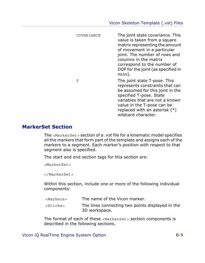
Vicon Skeleton Template (.vst) Files
ViconiQ_Option_RTE.book Page 9 Tuesday, June 21, 2005 2:53 PM
MarkerSet Section
The <MarkerSet> section of a .vst file for a kinematic model specifies all the markers that form part of the template and assigns each of the markers to a segment. Each marker’s position with respect to that segment also is specified.
The start and end section tags for this section are:
<MarkerSet>...
</MarkerSet>
Within this section, include one or more of the following individual components:
The format of each of these <MarkerSet> section components is described in the following sections.
COVARIANCE The joint state covariance. This value is taken from a square matrix representing the amount of movement in a particular joint. The number of rows and columns in the matrix correspond to the number of DOF for the joint (as specified in MEAN).
T The joint state T-pose. This represents constraints that can be assumed for this joint in the specified T-pose. State variables that are not a known value in the T-pose can be replaced with an asterisk (*) wildcard character.
<Markers> The name of the Vicon marker.
<Sticks> The lines connecting two points displayed in the 3D workspace.
Vicon iQ RealTime Engine System Option B-9

Vicon Skeleton Template (.vst) Files
ViconiQ_Option_RTE.book Page 10 Tuesday, June 21, 2005 2:53 PM
Markers
The <Markers> component of the <MarkerSet> section defines the Vicon markers for a human kinematic model.
A segment is defined by the markers, so the template must constrain the local coordinate systems of the segments with respect to the markers being tracked.
The format of this component is:
<Markers><Marker NAME="" POSITION="" SEGMENT="" COVARIANCE=""/>...
</Markers>
where:
NAME is the name of the Vicon marker, for example, LELB.
If you are using Workstation, this must match the name of the marker in the corresponding .mkr file.
POSITION is the position of the marker in the coordinate frame of the segment to which it is attached in x y z format.
The position can be specified as a mixture of numerical values (in millimeters) and NAME values from a <parameter> specified in the <Parameters> section of the .vst file. For example, the position of the RANK marker could be specified as:
POSITION="RANKx -50 -Shin"
SEGMENT is the segment to which the marker is attached.
COVARIANCE is the movement covariance for the marker. This value is taken from a 3 x 3 square matrix representing the accuracy with which the marker is located in the segment’s local coordinate system.
B-10 Vicon iQ RealTime Engine System Option

Vicon Skeleton Template (.vst) Files
ViconiQ_Option_RTE.book Page 11 Tuesday, June 21, 2005 2:53 PM
Sticks
The <Sticks> component of the <MarkerSet> section defines two markers between which a line is to be drawn in the 3D Workspace. Sticks are a visual aid to illustrate the connection between reconstructed marker positions or between virtual points created by a kinematic model. Sticks have no significance other than enabling the user to visualize the relationship between two specified points. The user can turn off the display of sticks if desired.
The format of this component is:
<Sticks><Stick MARKER1="" MARKER2="" RGB=""/>...
</Sticks>
where:
MARKER1 is the first marker from which to start drawing the stick.
MARKER2 is the second marker to which to connect the end of the stick.
RGB is the color of the stick, specified in RGB (Red Green Blue) format, for example 255 0 0 is the color red.
Vicon iQ RealTime Engine System Option B-11

Vicon Skeleton Template (.vst) Files
ViconiQ_Option_RTE.book Page 12 Tuesday, June 21, 2005 2:53 PM
B-12 Vicon iQ RealTime Engine System Option

ViconiQ_Option_RTE.book Page 1 Tuesday, June 21, 2005 2:53 PM
CCMarker P lacement in V icon iQ
In order for the Vicon Skeleton (.vsk) file for a RealTime subject to be correctly calibrated and data labeled, Vicon markers must be placed on specified locations on the subject whose movements are to be captured.
The correspondence between marker positions and labels are defined in the Vicon Skeleton Template (.vst) files. You must use a .vst file when preparing a RealTime subject in Vicon iQ (for details, see Chapter 4 Preparing a RealTime Subject in Vicon iQ). For details on the format and structure of .vst files, see Appendix B Vicon Skeleton Template (.vst) Files.
Sample .vst files for the human body are provided in the Vicon Models folder (by default, C:\Program Files\Vicon\Models \VICONiQ 2.0). The sample files iQProductionExample_V5.vst and iQ_HumanRTKM_V1.vst describe a kinematic model and marker arrangements for human subjects. They are suitable for general use.
This appendix illustrates where on a human subject to place the markers to correspond with labels defined in the iQProductionExample_V5.vst sample .vst file. If you create your own .vst files, you may find it helpful to create figures similar to the ones in this appendix.
Placement of Markers in Sample .vst File
This section shows you where on a human subject to place the markers corresponding to the labels in the iQProductionExample_V5.vst sample .vst file. It provides front, back, and side views. Some markers are shown from two views to help you accurately determine their position on your subject.
Vicon iQ RealTime Engine System Option C-1
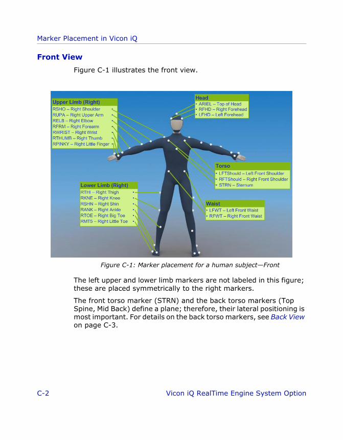
Marker Placement in Vicon iQ
ViconiQ_Option_RTE.book Page 2 Tuesday, June 21, 2005 2:53 PM
Front View
Figure C-1 illustrates the front view.
Figure C-1: Marker placement for a human subject—Front
The left upper and lower limb markers are not labeled in this figure; these are placed symmetrically to the right markers.
The front torso marker (STRN) and the back torso markers (Top Spine, Mid Back) define a plane; therefore, their lateral positioning is most important. For details on the back torso markers, see Back View on page C-3.
C-2 Vicon iQ RealTime Engine System Option

Marker Placement in Vicon iQ
ViconiQ_Option_RTE.book Page 3 Tuesday, June 21, 2005 2:53 PM
Back View
Figure C-3 illustrates the back view.
Figure C-2: Marker placement for a human subject—Back
The right upper and lower limb markers are not labeled in this figure; these are placed symmetrically to the left markers.
The front torso marker (STRN) and the back torso markers (Top Spine, Mid Back) define a plane; therefore, their lateral positioning is most important. For details on the front torso markers, see Front View on page C-2.
The Pelvis marker has no symmetrical marker on the left side; this asymmetry helps the autolabeling routine determine right from left on the subject.
Vicon iQ RealTime Engine System Option C-3

Marker Placement in Vicon iQ
ViconiQ_Option_RTE.book Page 4 Tuesday, June 21, 2005 2:53 PM
Side View
Figure C-3 illustrates a side view.
Figure C-3: Marker placement for a human subject—Side
C-4 Vicon iQ RealTime Engine System Option

ViconiQ_Option_RTE.book Page 1 Tuesday, June 21, 2005 2:53 PM
DDT roubleshoot ing
This appendix provides information on resolving problems that you may encounter when configuring or using the RealTime Engine in Vicion iQ.
ImportantIf you have additional questions or require further assistance, log on to our Web-accessible knowledge base, Vicon Online Support (VOS), at http://support.vicon.com) or contact Vicon Support at [email protected]. For details, see Appendix E Support Resources.
Performance Speed
Problems with the RealTime Engine acquiring or streaming data slowly generally are caused by the PC on which the RealTime Engine is installed having insufficient processor speed. If you are experiencing problems with the RealTime Engine running slowly, try these suggestions.
• Run the RealTime Engine on a PC with a faster processor speedFor general guidance on which PC in a Vicon system to install RealTime Engine, see Chapter 1 Introduction. Your Vicon Sales representative or your nearest agent or distributor can help you to identify the requirements for your specific needs.
• Reduce the number of cameras or markersThis reduces the amount of data that the Vicon system needs to process.
• Reduce the trajectory prediction error parameterIf your application does not involve the tracking of fast movements, consider reducing the value of this parameter in the RealTime Engine - Edit Options dialog box. For details, see Appendix A RealTime Engine Parameters.
Vicon iQ RealTime Engine System Option D-1

Troubleshooting
ViconiQ_Option_RTE.book Page 2 Tuesday, June 21, 2005 2:53 PM
• Use the Windows Classic theme rather than the Windows XP (or similar) themeThe Windows XP theme has a higher graphics overhead than the Windows Classic theme, which slows down the refresh rate for displaying new windows and dialog boxes. To change your desktop theme, in Control Panel double-click Display. In the Display Properties dialog box, click the Themes tab and select the Windows Classic theme.
• Disable any unused network protocolsDisable any network protocols that are not being used. To do this, open the Local Area Connection Properties page, clear the unused protocols and click OK. Restart your PC for the changes to take effect.
• Disable antivirus softwareSome antivirus programs may cause problems if they are running at the same time as the RealTime Engine. For instructions on how to temporarily disable your antivirus software, see the documentation supplied with it.
• Remove any background processesYou can set Windows to allow a greater proportion of your PC’s processor time to the RealTime Engine when it is running. To do this, remove any unneeded background processes that might be running in the Notification area at the far right side of the Windows task bar or that are specified in the Windows Startup folder. For details, see the help for the Windows Taskbar and Start Menu Properties dialog box.
• Apply latest driver updatesIf you notice graphics corruption or severe performance problems while streaming real-time data in Vicion iQ, ensure that the display adapter installed in your PC has had any available driver updates applied. For details on obtaining and installing driver updates, see the documentation supplied with your video adapters or the manufacturer's Web site.
• Ensure your display adapter supports OpenGL Vicon iQ 2.0 supports only hardware OpenGL acceleration. Ensure that your display adapter supports the OpenGL standard. For
D-2 Vicon iQ RealTime Engine System Option

Troubleshooting
ViconiQ_Option_RTE.book Page 3 Tuesday, June 21, 2005 2:53 PM
example, NVIDIA GeForce 6800 display adapters provide full OpenGL support.
• Disable vertical synchronization on your display adapterYou may notice an improvement in performance if you disable vertical synchronization on your display adapter. Removing this link between the monitor's vertical refresh rate and an application's rendering rate can increase the speed at which Vicon iQ renders its 3D and 2D Workspace windows. You can change this display setting in the advanced properties dialog box for your display adapter. From Windows Control Panel, double-click Display. In the Display Properties dialog box, click the Settings tab then click the Advanced button. In the advanced dialog box, click the tab for your display adapter and then select the options to disable vertical synchronization. For example, for an NVIDIA GeForce display adapter, select Performance and Quality Settings, then in the Global driver settings area, select Vertical sync and then clear the Application-controlled check box.
Accessing RealTime Engine on a Remote PC
If you are experiencing problems linking from Vicion iQ on the host PC to the RealTime Engine on a remote PC, try these suggestions in the order listed.
• Ensure that the correct IP address has been enteredDouble-check that the IP address for the PC on which the RealTime Engine is installed is valid and is correctly entered. For details on where to specify the IP address in your chosen Vicon application software, see Chapter 5 Streaming RealTime Data in Vicon iQ.
• Ensure that the IP addresses for the host and remote PCs are in the same rangeIn order to communicate over your network, PCs in a Vicon system must have an IP address in the same range; that is, the IP address details must be the same except for the machine-specific number after the final dot. For example, if the host PC on which Vicion iQ is installed has an IP address of 123.456.78.1, the remote PC on which the RealTime Engine is installed should have an IP address
Vicon iQ RealTime Engine System Option D-3

Troubleshooting
ViconiQ_Option_RTE.book Page 4 Tuesday, June 21, 2005 2:53 PM
beginning with 123.456.78. and ending with a unique number, for example 123.456.78.2.
From the Windows Command Prompt on each PC, use the Internet Protocol configuration settings command to identify the IP address assigned to a PC:
ipconfig
Note that this is not the Vicon ethernet network. Check with your network administrator if you are in doubt about the IP address range for your organization’s communications network.
• Ensure that the subnet mask for the host and remote PCs is the sameSubnet masks are used by TCP/IP services to determine whether a given IP address on an internal network is a local or remote network address. Depending on your network setup, various subnet masks may be in use. Check with your network administrator if you are in doubt about what it should be set to for PCs in your Vicon system.
From the Windows Command Prompt on each PC, use the Internet Protocol configuration settings command to identify the subnet mask for the PC:
ipconfig
• Ensure that all network services are runningThe network services must be running to enable communications between PCs in a Vicon system.
From Windows Event Viewer, look at the Event Log to identify any problems with the network services. You can access the Event Viewer by double-clicking Administrative Tools in Windows Control Panel.
• Check that you can ping the host and remote PCsThe Ping command is used to verify connections to a PC on a TCP/IP network.
D-4 Vicon iQ RealTime Engine System Option

Troubleshooting
ViconiQ_Option_RTE.book Page 5 Tuesday, June 21, 2005 2:53 PM
From the Windows Command Prompt, use a Ping command similar to the following for each PC:
ping 192.168.10.1
You should receive a response indicating that a reply was received, along with any relevant statistics.
• Ensure that Vicion iQ and the RealTime Engine can communicate on the same PCInstall the Vicion iQ software on the remote PC with the RealTime Engine and test that they can connect. If they can, network communications problems may be the issue. Contact your network administrator for assistance.
Vicon iQ RealTime Engine System Option D-5
Troubleshooting
ViconiQ_Option_RTE.book Page 6 Tuesday, June 21, 2005 2:53 PM
D-6 Vicon iQ RealTime Engine System Option

ViconiQ_Option_RTE.book Page 1 Tuesday, June 21, 2005 2:53 PM
EESupport Resources
This appendix describes the resources available to you to obtain support for your use of the RealTime Engine in Vicion iQ. It also provides instructions on obtaining information from Vicon Online Support (VOS) on the Web.
Technical Support
Vicon Peak offers telephone, email, and online technical support.
Telephone
You can speak with Support Engineers in the US and UK offices:
• California+1 (949) 472 9140 9:00 a.m. to 5:00 p.m. Pacific Time
• Colorado+1 (303) 799 8686 9:00 a.m. to 5:00 p.m. Mountain Time
• UK +44 (0)1865 261 800 9:00 am to 5:00 pm Greenwich Mean Time
You can raise feature requests, bugs, and support issues via email:
World Wide Web
You can access support areas and FAQs on our Web-accessible knowledge base, Vicon Online Support (VOS):
http://support.vicon.com
Vicon iQ RealTime Engine System Option E-1

Support Resources
ViconiQ_Option_RTE.book Page 2 Tuesday, June 21, 2005 2:53 PM
For further details on using this online Technical Support service, see Vicon Online Support (VOS) on page B-1.
Useful References
Vicon 3D motion capture and analysis systems have been applied to technologies in the fields of human movement sciences, clinical analysis, computer animation, and engineering around the world.
You can use these resources to keep up-to-date with Vicon developments:
• Vicon NewslettersYou can register to receive Vicon newsletters via email for your field of interest by:
• Completing the form on the Contact page of our Web site:
http://www.viconpeak.com/contact/
• Sending an email request to:
• The StandardYou can view the latest issue of The Standard online or subscribe to receive a printed copy from the Web site:
http://www.viconstandard.org/
This publication contains articles on motion analysis in science and engineering research and application projects. Articles are contributed by practicing experts and leading authorities in laboratories throughout the world.
Vicon Online Support (VOS)
This section explains how to locate answers and solutions to product queries in the Vicon Online Support (VOS) knowledge base on the Web. VOS enables you to quickly locate topics providing answers to previous questions, submit new questions, and maintain details of interest to you.
E-2 Vicon iQ RealTime Engine System Option
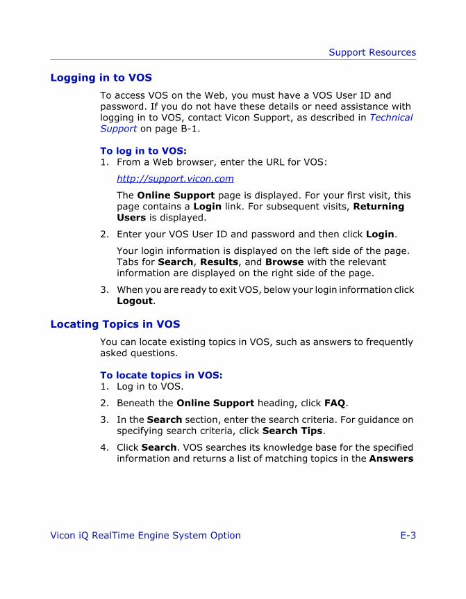
Support Resources
ViconiQ_Option_RTE.book Page 3 Tuesday, June 21, 2005 2:53 PM
Logging in to VOS
To access VOS on the Web, you must have a VOS User ID and password. If you do not have these details or need assistance with logging in to VOS, contact Vicon Support, as described in Technical Support on page B-1.
To log in to VOS:1. From a Web browser, enter the URL for VOS:
http://support.vicon.com
The Online Support page is displayed. For your first visit, this page contains a Login link. For subsequent visits, Returning Users is displayed.
2. Enter your VOS User ID and password and then click Login.
Your login information is displayed on the left side of the page. Tabs for Search, Results, and Browse with the relevant information are displayed on the right side of the page.
3. When you are ready to exit VOS, below your login information click Logout.
Locating Topics in VOS
You can locate existing topics in VOS, such as answers to frequently asked questions.
To locate topics in VOS:1. Log in to VOS.
2. Beneath the Online Support heading, click FAQ.
3. In the Search section, enter the search criteria. For guidance on specifying search criteria, click Search Tips.
4. Click Search. VOS searches its knowledge base for the specified information and returns a list of matching topics in the Answers
Vicon iQ RealTime Engine System Option E-3

Support Resources
ViconiQ_Option_RTE.book Page 4 Tuesday, June 21, 2005 2:53 PM
Found area at the bottom of the page, similar to that shown in Figure E-1.
Figure E-1: VOS FAQ Results
If search results are contained on multiple pages, from the Page drop-down list, select another page and click Go.
5. Click an entry in the Summary column to view the topic in a separate browser window.
6. Click the Notify Me by E-mail if this Answer is Updated button in the topic page if you want to automatically receive an email if the topic is updated in the future. Topic text may be updated as a result of further queries or product changes.
7. Rate the usefulness of the topic by clicking a value under How well did this answer your question and then clicking Submit Rating.
8. Click a hyperlink under the Related Answers to display another topic in the browser window.
E-4 Vicon iQ RealTime Engine System Option

Support Resources
ViconiQ_Option_RTE.book Page 5 Tuesday, June 21, 2005 2:53 PM
9. When you are through, click Close Window.
Submitting Questions to VOS
If you cannot locate the information you need in VOS, you can submit your own question.
To submit a new question to VOS:1. Log in to VOS.
2. Beneath the Online Support heading, click Ask a Question.
The Ask a Question page is displayed, similar to that shown in Figure E-2. The actual details displayed on this page depend on the settings in your Account Profile.
Figure E-2: VOS Find Answers page
3. Complete the fields in the Question Data, Additional Information, and Attach Documents to Question (if applicable) sections and click Submit Question.
Vicon iQ RealTime Engine System Option E-5

Support Resources
ViconiQ_Option_RTE.book Page 6 Tuesday, June 21, 2005 2:53 PM
A list of any previous FAQs that may be relevant to your question is displayed in the Preliminary Response to Question section.
4. Click on any of the suggested hyperlinks, or if they do not answer your question, click Finish Submitting Question to send your new question to VOS.
VOS Topics on RealTime Engine Issues
This section identifies a number of VOS topics on RealTime Engine issues that you may find useful when configuring or using it in Vicion iQ. It also describes how to obtain the latest version of the Vicion iQ software from VOS.
General RealTime Engine Issues
This list provides the titles and Answer IDs of general RealTime Engine issues to enable you to quickly locate the topic in VOS:
• PC Specifications and Recommendations for Vicon Software (824)
• Measuring Real Time Latency (719)
• What are the details of the Real Time Data Stream? (446)
• What 3rd-party computer graphics applications support Vicon Offline and RealTime data (8)
If you are viewing the PDF version of this book, you can use the hyperlinks in the list above to go directly to a given VOS topic. Ensure that you are logged onto VOS, then click the hyperlink for the Answer ID. Alternatively, you can enter the Answer ID or the VOS topic title in the Search Text field on the VOS FAQ page. For details on locating topics in VOS, see Vicon Online Support (VOS) on page E-2.
Software Downloads
Depending on the settings in your Account Profile, you can download the latest version of Vicon software from VOS.
On the FAQ page, enter the following details in the Search section:
• Product: Select the appropriate product from the drop-down list (e.g. Workstation Software, Vicon iQ, Polygon Authoring Tool, Cameras)
E-6 Vicon iQ RealTime Engine System Option
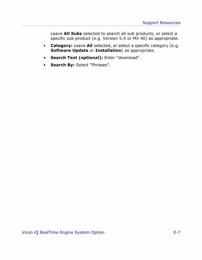
Support Resources
ViconiQ_Option_RTE.book Page 7 Tuesday, June 21, 2005 2:53 PM
Leave All Subs selected to search all sub products, or select a specific sub product (e.g. Version 5.X or MX 40) as appropriate.
• Category: Leave All selected, or select a specific category (e.g. Software Update or Installation) as appropriate.
• Search Text (optional): Enter "download".
• Search By: Select "Phrases".
Vicon iQ RealTime Engine System Option E-7

Support Resources
ViconiQ_Option_RTE.book Page 8 Tuesday, June 21, 2005 2:53 PM
E-8 Vicon iQ RealTime Engine System Option
ViconiQ_Option_RTE.book Page 1 Tuesday, June 21, 2005 2:53 PM
FFDocumentat ion Feedback
At Vicon Peak, we are working to develop comprehensive and easy-to-use documentation to support your use of our products. We welcome your comments or suggestions on how we can continue to improve our product documentation.
Please provide your documentation feedback using Vicon Online Support (VOS) at http://support.vicon.com. For details on VOS, see Appendix C Support Resources.
Please include “Documentation Feedback” in the Summary line and provide the following details in the body of your message:
• Product details• Product name, version number, and build number
• Document details• Document title and revision number or copyright date
• Document type and content location:
• Problem description• Brief description of current content, identifying your concerns
(e.g. specify any factual inaccuracies, errors, or omissions; grammatical errors; navigation or information location problems)
• Feedback details• Your suggestions for correcting or improving the
documentation
Book Chapter title, section title, and page number
Help Topic title and section title
Release document
Document title and section title
Vicon iQ RealTime Engine System Option F-1
Documentation Feedback
ViconiQ_Option_RTE.book Page 2 Tuesday, June 21, 2005 2:53 PM
F-2 Vicon iQ RealTime Engine System Option
Index
Numerics3rd-party applications 1-5
Aadding operation 3-4attaching markers 4-3
C.c3d files 1-6–1-7capturing RoM trials 4-4checking subject calibration 4-18circle fitting parameters A-2configuring parameters 2-1, 2-3configuring RTE 2-1configuring system settings 2-5.cp files 1-6, A-11
Ddata streaming 5-1documentation feedback F-1dongle viidynamic trials
RoM 3-2
EEclipse database 1-2, 3-1
Ffiles
.c3d 1-6–1-7
.cp 1-6, A-11
.mkr B-10sample 1-7, C-1.trial 1-6–1-7.tvd A-11.vsk 1-5, 1-7, 4-1, 4-13,
4-17–4-18, 5-1, A-21, C-1
.vst 1-5–1-7, 3-1, 3-6, 4-1, 4-3, 4-13, 4-15, B-1, C-1
.x2d A-11
.xml B-2
Ggenerating .vsk files 4-13graphics card 1-4
HHASP dongle vii
Kkinematic fit 4-18, 4-22kinematic fitting parameters A-7
Llicensing dongle vii
Mmarker covariances 4-18–4-19markers
attaching 4-3internal model A-2
MarkerSet section B-1, B-9Markers B-10Sticks B-11
.mkr files B-10motorcycle pose 3-3
Nneutral pose 3-3
motorcycle pose 3-3T-pose 3-3
Ooffline data streaming
parameters A-11
Vicon iQ RealTime Engine System Option Index-1

Index
operationadding to pipeline 3-4
PParameters section B-1pipeline
adding operation 3-4RoM trial processing 3-2RoM trials 3-4
preparing subject 4-1–4-2
RRange of Motion. See RoM trialsRealTime Engine - Edit Options 2-1,
2-3RealTime Engine Control 2-3recalibrating .vsk files 4-17reconstruction parameters A-12RoM trials 3-2
capturing 4-4neutral pose 3-3pipeline 3-4preparing for 3-6processing pipeline 3-2
RTE parameterscamera image noise level A-2camera noise factor A-12circle fitting A-2circle fitting error A-2configuring 2-1CP file name A-11enable grayscale fitter A-3enable/disable kinematic fit A-7fast circle fit threshold A-3fixed joint position tolerance A-21fixed labeling tolerance A-21incremental labeling
decisiveness A-22initial labeling decisiveness A-23kinematic filter prediction
order A-7
kinematic filter rotational prediction factor A-8
kinematic filter translational prediction factor A-9
kinematic fitting A-7labeling perseverance A-24marker statistics threshold A-25maximum circle diameter A-4maximum kinematic fit
iterations A-10maximum label iterations A-26minimum cameras to
reconstruct A-13minimum cameras to start
trajectory A-16minimum circle diameter A-4minimum circle fitting quality A-5minimum reconstruction
separation (mm) A-13offline data streaming A-11predictor order A-16proportional joint range
tolerance A-26proportional labeling
tolerance A-27ray intersect SDs A-14ray noise factor A-15reconstruction A-12relabeling perseverance A-27robust circle fit threshold A-5RT engine circle fit method A-6skip rate A-18trajectory fitting A-16trajectory labeling A-21trajectory prediction
error (mm/s) A-19TVD file name A-11X2D file name A-11
RTE system settings 2-5
Index-2 Vicon iQ RealTime Engine System Option
Index
Ssample .vst files 1-7, C-1setting up
Workstation 3-1Skeleton section B-1, B-5Software Developers Kit 1-5streaming data 5-1subject
preparing 4-1–4-2support
contact details E-1useful references E-2VOS E-2
system settingsconfiguring 2-5
system setup vii, 3-1
Ttechnical support E-1T-pose 3-3trajectory fitting parameters A-16trajectory labeling parameters A-21.trial files 1-6–1-7.tvd files A-11
Uuseful references E-2
VVicon MX vii, 1-1, 2-6Vicon Online Support. See VOSVicon V-series systems vii, 1-1, 2-5VOS
documentation feedback F-1support E-2
V-series systems xii.vsk files 1-5, 1-7, 4-1, 4-13, 4-17,
5-1, A-21, C-1checking 4-18generating 4-13recalibrating 4-17
.vst files 1-5–1-7, 3-1, 3-6, 4-1, 4-3, 4-13, 4-15, B-1, C-1
file format B-2file structure B-2MarkerSet section B-1, B-9Parameters section B-1sample 1-7, C-1Skeleton section B-1, B-5
Wworkflow 1-7
X.x2d files A-11.xml files B-2
Vicon iQ RealTime Engine System Option Index-3

Index
Index-4 Vicon iQ RealTime Engine System Option