vice guide 2002-2004 psylo & duke u-turn spring ser - sram · for exploded diagram and part...
TRANSCRIPT
For exploded diagram and part number information, refer to the Spare Parts Catalog available on our website atwww.rockshox.com.
Contact your local distributor or visit the RockShox website at www.rockshox.com for ordering information.
Information contained in this publication is subject to change at anytime without prior notice. For the latest technical information, visit our website at www.rockshox.com. Names used in this manual may be trademarks or registered trademarks of others.
© SRAM Corporation • September 2003 PN 95.4308.632.000, Rev. B 20
02
-20
04
PS
YL
O &
DU
KE
U-T
UR
N S
PR
ING
SE
RV
ICE
GU
IDE
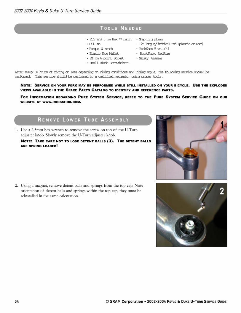
1. Use a 2.5mm hex wrench to remove the screw on top of the U-Turnadjuster knob. Slowly remove the U-Turn adjuster knob.NOTE: TAKE CARE NOT TO LOSE DETENT BALLS (3). THE DETENT BALLSARE SPRING LOADED!
2. Using a magnet, remove detent balls and springs from the top cap. Noteorientation of detent balls and springs within the top cap, they must bereinstalled in the same orientation.
• 2.5 and 5 mm Hex W rench • Snap ring pliers• Oil Pan • 12” long cylindrical rod (plastic or wood)• Torque W rench • RockShox 5 wt. Oil• Plastic Face Mallet • RockShox RedRum• 24 mm 6-point Socket • Safety Glasses• Small Blade Screwdriver
After every 50 hours of riding or less depending on riding conditions and riding style, the following service should beperformed. This service should be performed by a qualified mechanic, using proper tools.
NOTE: SERVICE ON YOUR FORK MAY BE PERFORMED WHILE STILL INSTALLED ON YOUR BICYCLE. USE THE EXPLODEDVIEWS AVAILABLE IN THE SPARE PARTS CATALOG TO IDENTIFY AND REFERENCE PARTS.
FOR INFORMATION REGARDING PURE SYSTEM SERVICE, REFER TO THE PURE SYSTEM SERVICE GUIDE ON OURWEBSITE AT WWW.ROCKSHOX.COM.
54 © SRAM Corporation • 2002-2004 PSYLO & DUKE U-TURN SERVICE GUIDE
2002-2004 Psylo & Duke U-Turn Service Guide
R E M O V E L O W E R T U B E A S S E M B L Y
T O O L S N E E D E D
1
2
NOTE: SERVICE DEPICTED AND DESCRIBED IN THIS GUIDE IS FOR HYDRACOILAND HC2 FORKS. THE SAME PROCEDURE FOR LOWER LEG REMOVAL STILLAPPLIES TO PURE SYSTEM FORKS.
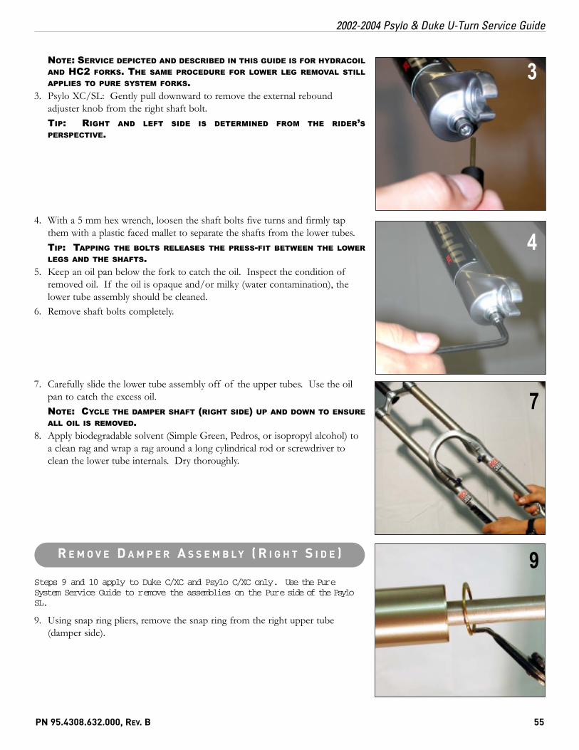
3. Psylo XC/SL: Gently pull downward to remove the external reboundadjuster knob from the right shaft bolt.TIP: RIGHT AND LEFT SIDE IS DETERMINED FROM THE RIDER’SPERSPECTIVE.
4. With a 5 mm hex wrench, loosen the shaft bolts five turns and firmly tapthem with a plastic faced mallet to separate the shafts from the lower tubes.TIP: TAPPING THE BOLTS RELEASES THE PRESS-FIT BETWEEN THE LOWERLEGS AND THE SHAFTS.
5. Keep an oil pan below the fork to catch the oil. Inspect the condition ofremoved oil. If the oil is opaque and/or milky (water contamination), thelower tube assembly should be cleaned.
6. Remove shaft bolts completely.
7. Carefully slide the lower tube assembly off of the upper tubes. Use the oilpan to catch the excess oil.NOTE: CYCLE THE DAMPER SHAFT (RIGHT SIDE) UP AND DOWN TO ENSUREALL OIL IS REMOVED.
8. Apply biodegradable solvent (Simple Green, Pedros, or isopropyl alcohol) toa clean rag and wrap a rag around a long cylindrical rod or screwdriver toclean the lower tube internals. Dry thoroughly.
Steps 9 and 10 apply to Duke C/XC and Psylo C/XC only. Use the PureSystem Service Guide to remove the assemblies on the Pure side of the PsyloSL.
9. Using snap ring pliers, remove the snap ring from the right upper tube(damper side).
PN 95.4308.632.000, REV. B 55
2002-2004 Psylo & Duke U-Turn Service Guide
3
4
7
9R E M O V E D A M P E R A S S E M B L Y ( R I G H T S I D E )
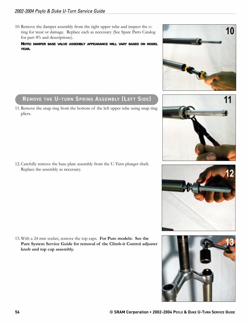
10. Remove the damper assembly from the right upper tube and inspect the o-ring for wear or damage. Replace each as necessary (See Spare Parts Catalogfor part #’s and descriptions).NOTE: DAMPER BASE VALVE ASSEMBLY APPEARANCE WILL VARY BASED ON MODELYEAR.
11. Remove the snap ring from the bottom of the left upper tube using snap ringpliers.
12. Carefully remove the base plate assembly from the U-Turn plunger shaft.Replace the assembly as necessary.
13. With a 24 mm socket, remove the top caps. For Pure models: See thePure System Service Guide for removal of the Climb-it Control adjusterknob and top cap assembly.
56 © SRAM Corporation • 2002-2004 PSYLO & DUKE U-TURN SERVICE GUIDE
2002-2004 Psylo & Duke U-Turn Service Guide
10
11
12
13
REMOVE THE U-TURN SPRING ASSEMBLY (LEFT SIDE)
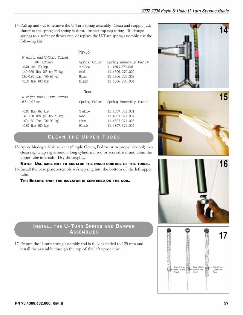
14. Pull up and out to remove the U-Turn spring assembly. Clean and reapply JudyButter to the spring and spring isolator. Inspect top cap o-ring. To changesprings to a softer or firmer rate, or replace the U-Turn spring assembly, use thefollowing kits:
PS Y L OW eight and U-Turn Travel
80-125mm Spring Color Spring Assembly Part #<140 lbs (63 kg) Yellow 11.4306.270.001140-160 lbs (63 to 70 kg) Red 11.4306.270.002160-180 lbs (70-80 kg) Blue 11.4306.270.003>180 lbs (80 kg) Black 11.4306.270.004
DUKEW eight and U-Turn Travel63-108mm Spring Color Spring Assembly Part #
<140 lbs (63 kg) Yellow 11.4307.371.001140-160 lbs (63 to 70 kg) Red 11.4307.371.002160-180 lbs (70-80 kg) Blue 11.4307.371.003>180 lbs (80 kg) Black 11.4307.371.004
15. Apply biodegradable solvent (Simple Green, Pedros or isopropyl alcohol) to aclean rag, wrap rag around a long cylindrical rod or screwdriver and clean theupper tube internals. Dry thoroughly.NOTE: USE CARE NOT TO SCRATCH THE INNER SURFACE OF THE TUBES.
16. Install the base plate assembly w/snap ring into the bottom of the left uppertube.TIP: ENSURE THAT THE ISOLATOR IS CENTERED ON THE COIL.
17. Ensure the U-turn spring assembly rod is fully extended to 125 mm andinstall the assembly through the top of the left upper tube.
PN 95.4308.632.000, REV. B 57
2002-2004 Psylo & Duke U-Turn Service Guide
14
15
16
C L E A N T H E U P P E R T U B E S
INSTALL THE U-TURN SPRING AND DAMPERASSEMBLIES
Psylo 125 mmDuke 108 mmTravel
Psylo 100 mmDuke 80 mmTravel
Psylo 80 mmDuke 63 mmTravel
17
18. Press firmly and hand thread the U-Turn top cap 1.5-2 turns to start threads andprevent stripping the top cap. With a 24 mm socket torque the U-turn top cap to40 in-lb.
19. Install the damper assembly into the right upper tube and insert the snap ring.20. Install springs and detent balls into the U-Turn top cap. Be sure to install
them in the same orientation that they were removed (see step 2 photo).21. Using a 2.5 mm hex wrench, install the U-Turn adjuster knob and screw. Torque
the screw to 12 in-lb.NOTE: DO NOT USE LOCTITE ON THE SCREW, IT WILL DAMAGE THE PLASTICU-TURN ADJUSTER KNOB
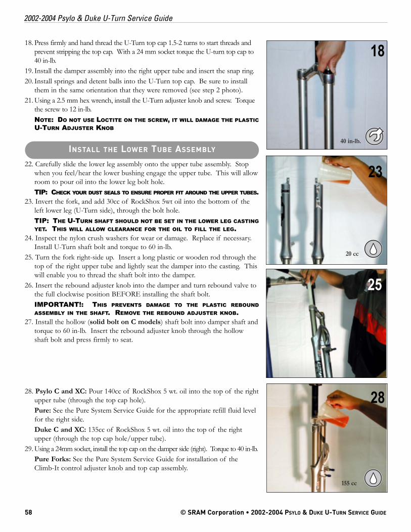
22. Carefully slide the lower leg assembly onto the upper tube assembly. Stopwhen you feel/hear the lower bushing engage the upper tube. This will allowroom to pour oil into the lower leg bolt hole.TIP: CHECK YOUR DUST SEALS TO ENSURE PROPER FIT AROUND THE UPPER TUBES.
23. Invert the fork, and add 30cc of RockShox 5wt oil into the bottom of theleft lower leg (U-Turn side), through the bolt hole.TIP: THE U-TURN SHAFT SHOULD NOT BE SET IN THE LOWER LEG CASTINGYET. THIS WILL ALLOW CLEARANCE FOR THE OIL TO FILL THE LEG.
24. Inspect the nylon crush washers for wear or damage. Replace if necessary.Install U-Turn shaft bolt and torque to 60 in-lb.
25. Turn the fork right-side up. Insert a long plastic or wooden rod through thetop of the right upper tube and lightly seat the damper into the casting. Thiswill enable you to thread the shaft bolt into the damper.
26. Insert the rebound adjuster knob into the damper and turn rebound valve tothe full clockwise position BEFORE installing the shaft bolt.IMPORTANT!: THIS PREVENTS DAMAGE TO THE PLASTIC REBOUNDASSEMBLY IN THE SHAFT. REMOVE THE REBOUND ADJUSTER KNOB.
27. Install the hollow (solid bolt on C models) shaft bolt into damper shaft andtorque to 60 in-lb. Insert the rebound adjuster knob through the hollowshaft bolt and press firmly to seat.
28. Psylo C and XC: Pour 140cc of RockShox 5 wt. oil into the top of the rightupper tube (through the top cap hole).Pure: See the Pure System Service Guide for the appropriate refill fluid levelfor the right side.Duke C and XC: 135cc of RockShox 5 wt. oil into the top of the rightupper (through the top cap hole/upper tube).
29. Using a 24mm socket, install the top cap on the damper side (right). Torque to 40 in-lb.Pure Forks: See the Pure System Service Guide for installation of theClimb-It control adjuster knob and top cap assembly.
58 © SRAM Corporation • 2002-2004 PSYLO & DUKE U-TURN SERVICE GUIDE
2002-2004 Psylo & Duke U-Turn Service Guide
25
28
23
155 cc
INSTALL THE LOWER TUBE ASSEMBLY
18
40 in-lb.
20 cc