vi brick white paper - mark allen
TRANSCRIPT

VI BRICK WHITE PAPER
vicorpower.com 800-735-6200 Rev. 1 2 / 2008
Page 1 of 10
Contents Page
Power ConversionArchitecture and FPA.......... 1
VI BRICK Voltage Transform-ation Module (VTM) .......... 2
VI BRICK Pre-RegulatorModule (PRM) .................... 4
VI BRICK PRM & VTMApplications ........................ 5
VI BRICK Bus Converter Module (BCM) .................... 6
Using FPA: Why Factorize?..7
Small size.......................... 7
Flexibility .......................... 7
Efficiency .......................... 9
Fast Transient .................. 9
Architecture .................. 10
Introduction
As electronic systems continue to trend toward lower voltages with higher currents andas the speed of contemporary loads – such as state-of-the-art processors and memory –continues to increase, the power systems designer is challenged to provide small, cost-effective and efficient solutions that offer the requisite performance. Traditional powerarchitectures cannot, in the long run, provide the required performance. Vicor’s newFactorized Power Architecture™ (FPA), and its new families of integrated powercomponents, called V•I Chips™ and VI BRICKs™, provide a revolutionary new andoptimal power conversion solution that addresses the challenge in every respect.
The Architectural Problems of Power Conversion
With each new generation of processor, memory, DSP and ASIC, the trend is towardlower voltages, higher currents, higher speeds and more onboard voltages. Systemdesigners are challenged to contend with a proliferation of lower voltages; provideever-faster transient response; improve overall power system efficiency; and do it allusing less board area.
Historically, a variety of power systems architectures have been adopted as solutions.Principal among them have been Centralized Power Architecture (CPA), DistributedPower Architecture (DPA) and Intermediate Bus Architecture (IBA).
CPA, one of the oldest power systems architectures, generates all system voltages at acentral location and distributes them to load locations via distribution buses. This canbe effective if the voltages are high and the currents low or if the distances betweenthe power supply and the loads are small. However, for low voltages and widelydistributed loads, the problem of distribution losses becomes unmanageable asdistribution power loss increases, due to the rising current (as power loss = I2R). Thebus cross-section would have to increase as the square of the reduction in the voltagein order to maintain constant distribution efficiency – an impractical solution in today’scomplex, low-voltage systems.
The introduction in the early 1980s of modular, high-density power converters, enabledthe migration to DPA and overcame some of the problems of CPA. The “bricks” of DPAdeliver all of the functions of a classic DC-DC converter – isolation, voltage transformationand regulation – at the point of load. A s onboard voltages proliferated, however, DPAsolutions required increasing numbers of bricks, thereby exacting a penalty in terms ofboard space and cost. Furthermore, typical DPA brick topologies are inadequate for thetransient response requirements of today’s fast loads.
Factorized Power Architecture and VI BRICKsFlexible, High Performance Power System Solutions

VI BRICK WHITE PAPER
vicorpower.com 800-735-6200 Rev. 1 2 / 2008
Page 2 of 10
Factorized Power Architecture (FPA): Solving theContemporary Power Conversion Problem
FPA uses Vicor’s power architecture research, and ASIC-based product developmentstrategy. The enabling components are integrated power components called ‘V•I Chipsand VI BRICKs‘ which set new standards in terms of density, efficiency, responsivenessand system cost and offer the power architect entirely new ways to solve power problems.
VI BRICK VTM (Voltage Transformation Module): Sine Amplitude Converter
The VI BRICK VTM (Fig. 1) — one of the building blocks of FPA — is a wide voltagerange input, high efficiency voltage transformation unit using a proprietary Zero-CurrentSwitching / Zero-Voltage Switching (ZCS / ZVS) Sine Amplitude Converter™ (SAC™).
A simplified schematic of a Sine Amplitude Converter is shown in Fig. 2. The powertrain is a low-charge (Q), high-frequency controlled oscillator, with high spectral purityand common-mode symmetry, resulting in essentially noise-free operation. The controlarchitecture locks the operating frequency to the power train resonant frequency,optimizing efficiency and minimizing output impedance by effectively canceling reactivecomponents. ROUT can be as low as 0.8 milliohm from a single VTM. If that is not lowenough, or if more power is required, VTMs can be paralleled with accurate currentsharing. Quiet and powerful, the SAC-based VTM can be considered as a linear voltage /current converter with a flat output impedance up to about 1 MHz.
Figure 1 – VI BRICK VTM Voltage Transformation Module
CRES
COUTCIN
+In
– In – Out
+ Out
1 2 1 2 1 2T1T1 T1
Figure 2 – Simplified schematic of the Sine Amplitude Converter
> Back to Page 1
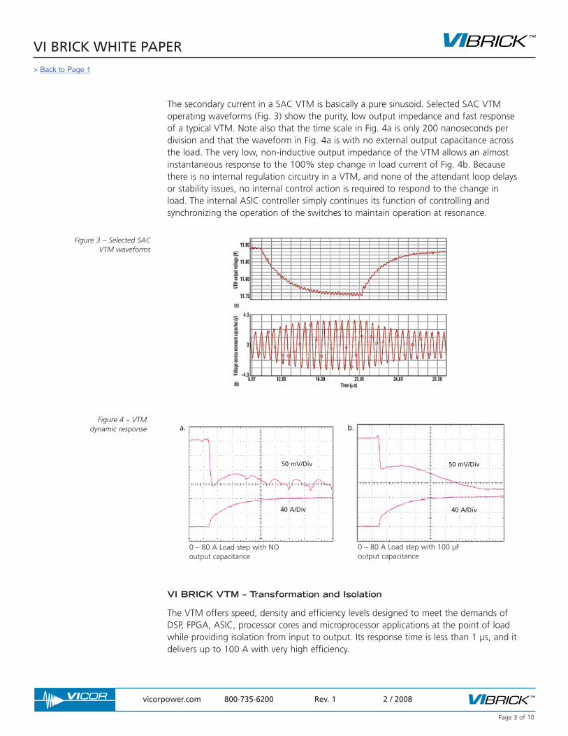
The secondary current in a SAC VTM is basically a pure sinusoid. Selected SAC VTMoperating waveforms (Fig. 3) show the purity, low output impedance and fast responseof a typical VTM. Note also that the time scale in Fig. 4a is only 200 nanoseconds perdivision and that the waveform in Fig. 4a is with no external output capacitance acrossthe load. The very low, non-inductive output impedance of the VTM allows an almostinstantaneous response to the 100% step change in load current of Fig. 4b. Becausethere is no internal regulation circuitry in a VTM, and none of the attendant loop delaysor stability issues, no internal control action is required to respond to the change inload. The internal ASIC controller simply continues its function of controlling andsynchronizing the operation of the switches to maintain operation at resonance.
VI BRICK VTM – Transformation and Isolation
The VTM offers speed, density and efficiency levels designed to meet the demands ofDSP, FPGA, ASIC, processor cores and microprocessor applications at the point of loadwhile providing isolation from input to output. Its response time is less than 1 µs, and itdelivers up to 100 A with very high efficiency.
VI BRICK WHITE PAPER
vicorpower.com 800-735-6200 Rev. 1 2 / 2008
Page 3 of 10
Figure 3 – Selected SACVTM waveforms
Figure 4 – VTM dynamic response a.
50 mV/Div
40 A/Div
0 – 80 A Load step with NOoutput capacitance
50 mV/Div
40 A/Div
b.
0 – 80 A Load step with 100 µF output capacitance
> Back to Page 1
VI BRICK WHITE PAPER
vicorpower.com 800-735-6200 Rev. 1 2 / 2008
Page 4 of 10
The VI BRICK VTM can be considered a fixed-ratio DC-DC transformer with thefollowing capabilities:
• input range compatible with 48 V and 24 V PRMs;• power up to 300 W or 100 A;• power density up to 390 W/in3;• efficiency up to 97%;• isolation to 2,250 Vdc in 2.08 in2 package;• low power dissipation at point of load;• low output impedance enabling fast transient response.
For DC-DC power conversion, the VTM is designed to operate with the PRM (see nextsection), which provides soft start, regulation, and the initial Vcc pulse at start up. Thispulse is received through the VTM control (VC) pin. Standalone VTM operation ispossible if a Vcc is available see Application Note AN:007 “Using VTMs as 26 – 55 VInput Bus Converters”.
VI BRICK PRM Pre-Regulator Module: An efficient buck-boost
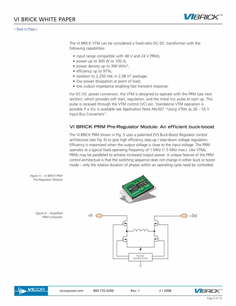
The VI BRICK PRM shown in Fig. 5 uses a patented ZVS Buck-Boost Regulator controlarchitecture (see Fig. 6) to give high efficiency step-up / step-down voltage regulation.Efficiency is maximized when the output voltage is close to the input voltage. The PRMoperates at a typical fixed operating frequency of 1 MHz (1.5 MHz max.). Like VTMs,PRMs may be paralleled to achieve increased output power. A unique feature of the PRMcontrol architecture is that the switching sequence does not change in either buck or boostmode – only the relative duration of phases within an operating cycle need be controlled.
+In + Out
Proprietary Buck-Boost Control
Figure 5 – VI BRICK PRM Pre-Regulator Module
Figure 6 – Simplified PRM schematic
> Back to Page 1
The PRM provides a regulated output voltage – a ‘factorized bus’ – from an unregulatedinput source. The combination of the PRM and VTM creates an isolated, regulated DC-DCconverter. PRMs can also be used stand alone as non-isolated voltage regulators. The VI BRICK PRM has the following attributes:
• input ranges of 18 – 36 V and 36 – 75 V• power up to 320 W• power density up to 416 W/in3
• efficiency up to 97%• 1.5 MHz switching frequency• up to 100°C baseplate operation
PRM+VTM Architectures and Applications
The PRM control system and supporting ASICs enable the VTM output voltage to becontrolled using a choice of methods.
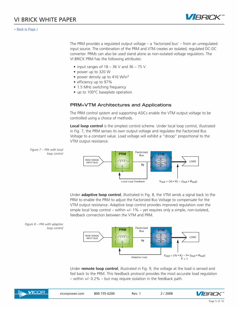
Local loop control is the simplest control scheme. Under local loop control, illustratedin Fig. 7, the PRM senses its own output voltage and regulates the Factorized BusVoltage to a constant value. Load voltage will exhibit a “droop” proportional to theVTM output resistance.
Under adaptive loop control, illustrated in Fig. 8, the VTM sends a signal back to thePRM to enable the PRM to adjust the Factorized Bus Voltage to compensate for theVTM output resistance. Adaptive loop control provides improved regulation over thesimple local loop control – within +/- 1% – yet requires only a simple, non-isolated,feedback connection between the VTM and PRM.
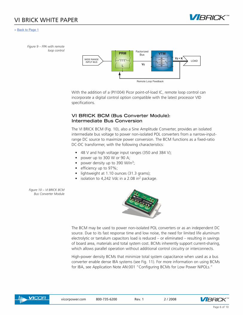
Under remote loop control, illustrated in Fig. 9, the voltage at the load is sensed andfed back to the PRM. This feedback protocol provides the most accurate load regulation– within +/- 0.2% – but may require isolation in the feedback path.
VI BRICK WHITE PAPER
vicorpower.com 800-735-6200 Rev. 1 2 / 2008
Page 5 of 10
Figure 8 – FPA with adaptiveloop control
WIDE RANGEINPUT BUS LOAD
PRM
LN
PN
S
VTMFactorized
Bus
Local Loop Feedback Vout = (Vf • K) – (Iout • Rout)
Vf
Figure 7 – FPA with localloop control
WIDE RANGEINPUT BUS LOAD
PRM
LN
PN
S
VTMFactorized
Bus
Adaptive LoopVout = (Vf • K) – F• (Iout • Rout)
F < 1
Vf
> Back to Page 1
VI BRICK WHITE PAPER
vicorpower.com 800-735-6200 Rev. 1 2 / 2008
Page 6 of 10
With the addition of a (PI1004) Picor point-of-load IC, remote loop control canincorporate a digital control option compatible with the latest processor VIDspecifications.
VI BRICK BCM (Bus Converter Module): Intermediate Bus Conversion
The VI BRICK BCM (Fig. 10), also a Sine Amplitude Converter, provides an isolatedintermediate bus voltage to power non-isolated POL converters from a narrow-input-range DC source to maximize power conversion. The BCM functions as a fixed-ratioDC-DC transformer, with the following characteristics:
• 48 V and high voltage input ranges (350 and 384 V);• power up to 300 W or 90 A;• power density up to 390 W/in3;• efficiency up to 97%;• lightweight at 1.10 ounces (31.3 grams);• isolation to 4,242 Vdc in a 2.08 in2 package.
The BCM may be used to power non-isolated POL converters or as an independent DCsource. Due to its fast response time and low noise, the need for limited life aluminumelectrolytic or tantalum capacitors load is reduced – or eliminated – resulting in savingsof board area, materials and total system cost. BCMs inherently support current-sharing,which allows parallel operation without additional control circuitry or interconnects.
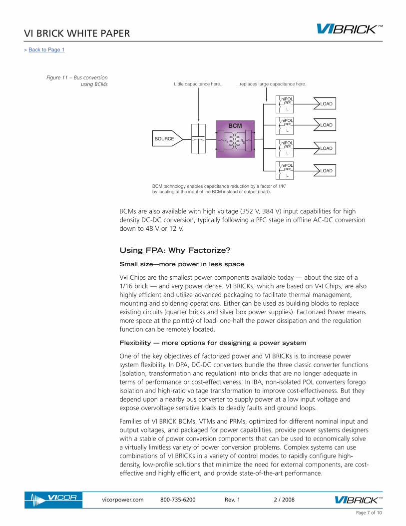
High-power density BCMs that minimize total system capacitance when used as a busconverter enable dense IBA systems (see Fig. 11). For more information on using BCMsfor IBA, see Application Note AN:001 “Configuring BCMs for Low Power NiPOLs.”
Figure 9 – FPA with remoteloop control
WIDE RANGEINPUT BUS LOAD
PRM
LN
PN
S
VTMFactorized
Bus
Remote Loop Feedback
Vf
Vf • K
Figure 10 – VI BRICK BCM Bus Converter Module
> Back to Page 1
VI BRICK WHITE PAPER
vicorpower.com 800-735-6200 Rev. 1 2 / 2008
Page 7 of 10
BCMs are also available with high voltage (352 V, 384 V) input capabilities for highdensity DC-DC conversion, typically following a PFC stage in offline AC-DC conversiondown to 48 V or 12 V.
Using FPA: Why Factorize?
Small size—more power in less space
V•I Chips are the smallest power components available today — about the size of a1/16 brick — and very power dense. VI BRICKs, which are based on V•I Chips, are alsohighly efficient and utilize advanced packaging to facilitate thermal management,mounting and soldering operations. Either can be used as building blocks to replaceexisting circuits (quarter bricks and silver box power supplies). Factorized Power meansmore space at the point(s) of load: one-half the power dissipation and the regulationfunction can be remotely located.
Flexibility — more options for designing a power system
One of the key objectives of factorized power and VI BRICKs is to increase powersystem flexibility. In DPA, DC-DC converters bundle the three classic converter functions(isolation, transformation and regulation) into bricks that are no longer adequate interms of performance or cost-effectiveness. In IBA, non-isolated POL converters foregoisolation and high-ratio voltage transformation to improve cost-effectiveness. But theydepend upon a nearby bus converter to supply power at a low input voltage andexpose overvoltage sensitive loads to deadly faults and ground loops.
Families of VI BRICK BCMs, VTMs and PRMs, optimized for different nominal input andoutput voltages, and packaged for power capabilities, provide power systems designerswith a stable of power conversion components that can be used to economically solvea virtually limitless variety of power conversion problems. Complex systems can usecombinations of VI BRICKs in a variety of control modes to rapidly configure high-density, low-profile solutions that minimize the need for external components, are cost-effective and highly efficient, and provide state-of-the-art performance.
Figure 11 – Bus conversion using BCMs
SOURCE
LOAD
LOAD
LOAD
LOAD
NP
NS
BCM
L
niPOL
L
niPOL
L
niPOL
L
niPOL
Little capacitance here... ...replaces large capacitance here.
BCM technology enables capacitance reduction by a factor of 1/K2 by locating at the input of the BCM instead of output (load).
> Back to Page 1
VI BRICK WHITE PAPER
vicorpower.com 800-735-6200 Rev. 1 2 / 2008
Page 8 of 10
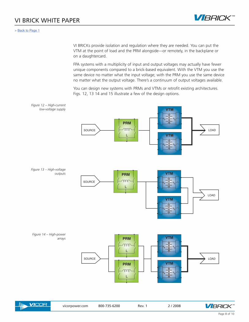
VI BRICKs provide isolation and regulation where they are needed. You can put theVTM at the point of load and the PRM alongside—or remotely, in the backplane or on a daughtercard.
FPA systems with a multiplicity of input and output voltages may actually have fewerunique components compared to a brick-based equivalent. With the VTM you use thesame device no matter what the input voltage; with the PRM you use the same deviceno matter what the output voltage. There’s a continuum of output voltages available.
You can design new systems with PRMs and VTMs or retrofit existing architectures.Figs. 12, 13 14 and 15 illustrate a few of the design options.
PRM
L
NP NS
VTM
NP NS
VTM
LOADSOURCE
Figure 12 – High-current low-voltage supply
SOURCE
LOAD
PRM
L
NP NS
VTM
NP NS
VTMFigure 13 – High-voltage
outputs
SOURCE LOAD
PRM
L
PRM
L
NP
NS
VTM
NP
NS
VTM
Figure 14 – High-powerarrays
> Back to Page 1
VI BRICK WHITE PAPER
vicorpower.com 800-735-6200 Rev. 1 2 / 2008
Page 9 of 10
SOURCE LOAD #1
LOAD #2
LOAD #3
PRM
LN
PN
S
VTM
NP
NS
VTM
NP
NS
VTM
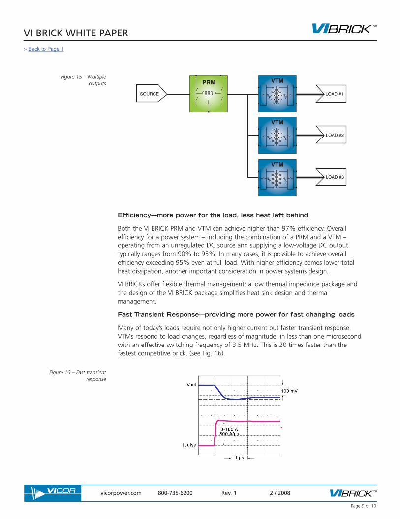
Figure 15 – Multiple outputs
Figure 16 – Fast transient response
Efficiency—more power for the load, less heat left behind
Both the VI BRICK PRM and VTM can achieve higher than 97% efficiency. Overallefficiency for a power system – including the combination of a PRM and a VTM –operating from an unregulated DC source and supplying a low-voltage DC outputtypically ranges from 90% to 95%. In many cases, it is possible to achieve overallefficiency exceeding 95% even at full load. With higher efficiency comes lower totalheat dissipation, another important consideration in power systems design.
VI BRICKs offer flexible thermal management: a low thermal impedance package andthe design of the VI BRICK package simplifies heat sink design and thermalmanagement.
Fast Transient Response—providing more power for fast changing loads
Many of today’s loads require not only higher current but faster transient response.VTMs respond to load changes, regardless of magnitude, in less than one microsecondwith an effective switching frequency of 3.5 MHz. This is 20 times faster than thefastest competitive brick. (see Fig. 16).
> Back to Page 1

VI BRICK WHITE PAPER
vicorpower.com 800-735-6200 Rev. 1 2 / 2008
Page 10 of 10
The VTM's high bandwidth obsoletes the need for massive point-of-load bypasscapacitance. Even without any external output capacitors, the output of a VTM exhibitsa limited voltage perturbation in response to a sudden power surge. A minimal amountof external bypass capacitance, in the form of low ESR / ESL ceramic capacitors, sufficesto eliminate any transient voltage overshoot.
Architecture – IBA, niPOLs and VI BRICKs
IBA has proven effective as an interim method of containing power system cost whileaddressing the trend toward a proliferation of lower load voltages. IBA relies on non-isolated point-of-load regulators (niPOLs), reducing the POL function to regulation andtransformation. The niPOLs operate from an intermediate bus voltage provided byupstream isolated converters. However, traditional IBA has inherent limitations that requiretrade-offs between distribution and conversion loss and that limit responsiveness to rapidload changes. VI BRICK BCMs can be used to solve these problems and several others.
Conclusion
FPA and VI BRICKs offer a power conversion architecture and enabling power buildingblocks that overcome these limitations while providing higher performance in everycritical system specification. Factorized power, in fact, maximizes the competitiveness ofa power system by providing the highest degree of system flexibility, power density,conversion efficiency, transient responsiveness, noise performance, and field reliability.
VI BRICK Application Notes and White Papers
AN:001 – Configuring the Vicor BCM with low power niPOLs
AN:002 – PRM / VTM Parallel Operation
AN:003 – Powering Multiple VTMs with a Single PRM
AN:005 – FPA Printed Circuit Board Layout Guidelines
AN:007 – Using VTMs as 26 – 55 V Input Bus Converters
AN:016 – Using BCM™ Bus Converters in High Power Arrays
White Paper – Innovative Power Device to Support Intermediate Bus Architecture Designs
White Paper – Enabling Next Generation High-Density Power Conversion
> Back to Page 1