vesda vlq product guide manuals/… · l basetransceiverstations(bts) l serverrooms l...
TRANSCRIPT
VESDA VLQProduct Guide
VLQ-100
October 2014
Document: 26104_06
Part Number: 30320

VESDA by Xtralis VESDA VLQProduct Guide
www.xtralis.com i
Intellectual Property and CopyrightThis document includes registered and unregistered trademarks. All trademarks displayed are the trademarks oftheir respective owners. Your use of this document does not constitute or create a licence or any other right to usethe name and/or trademark and/or label.
This document is subject to copyright owned by Xtralis AG (“Xtralis”). You agree not to copy, communicate to thepublic, adapt, distribute, transfer, sell, modify or publish any contents of this document without the express priorwritten consent of Xtralis.
DisclaimerThe contents of this document is provided on an “as is” basis. No representation or warranty (either express orimplied) is made as to the completeness, accuracy or reliability of the contents of this document. The manufacturerreserves the right to change designs or specifications without obligation and without further notice. Except asotherwise provided, all warranties, express or implied, including without limitation any implied warranties ofmerchantability and fitness for a particular purpose are expressly excluded.
General WarningThis product must only be installed, configured and used strictly in accordance with the General Terms andConditions, User Manual and product documents available from Xtralis. All proper health and safety precautionsmust be taken during the installation, commissioning and maintenance of the product. The system should not beconnected to a power source until all the components have been installed. Proper safety precautions must be takenduring tests and maintenance of the products when these are still connected to the power source. Failure to do soor tampering with the electronics inside the products can result in an electric shock causing injury or death and maycause equipment damage. Xtralis is not responsible and cannot be held accountable for any liability that may arisedue to improper use of the equipment and/or failure to take proper precautions. Only persons trained through anXtralis accredited training course can install, test and maintain the system.
LiabilityYou agree to install, configure and use the products strictly in accordance with the User Manual and productdocuments available from Xtralis.
Xtralis is not liable to you or any other person for incidental, indirect, or consequential loss, expense or damages ofany kind including without limitation, loss of business, loss of profits or loss of data arising out of your use of theproducts. Without limiting this general disclaimer the following specific warnings and disclaimers also apply:
Fitness for PurposeYou agree that you have been provided with a reasonable opportunity to appraise the products and have madeyour own independent assessment of the fitness or suitability of the products for your purpose. You acknowledgethat you have not relied on any oral or written information, representation or advice given by or on behalf of Xtralisor its representatives.
Total LiabilityTo the fullest extent permitted by law that any limitation or exclusion cannot apply, the total liability of Xtralis inrelation to the products is limited to:
1. in the case of services, the cost of having the services supplied again; or2. in the case of goods, the lowest cost of replacing the goods, acquiring equivalent goods or having the goods
repaired.
IndemnificationYou agree to fully indemnify and hold Xtralis harmless for any claim, cost, demand or damage (including legal costson a full indemnity basis) incurred or which may be incurred arising from your use of the products.
MiscellaneousIf any provision outlined above is found to be invalid or unenforceable by a court of law, such invalidity orunenforceability will not affect the remainder which will continue in full force and effect. All rights not expresslygranted are reserved.
VESDA VLQProduct Guide VESDA by Xtralis
ii www.xtralis.com
ScopeThe VESDA VLQProduct Guide provides a comprehensive description of the VLQ detector.
This guide introduces the VESDA VLQ features, technical specifications and gives an understanding of itscomponents and their function. You will also find instructions on installing, cabling and powering up thedetector.
This guide is for anyone involved with the design, maintenance and purchasing of a VESDA VLQ system. It isassumed that anyone using this product has the knowledge and appropriate certification from local fire andelectrical authorities.
Document ConventionsThe following typographic conventions are used in this document:
Convention DescriptionBold Used to denote: emphasis.
Used for names of menus, menu options, toolbar buttons
Italics Used to denote: references to other parts of this document or otherdocuments. Used for the result of an action.
The following icons are used in this document:
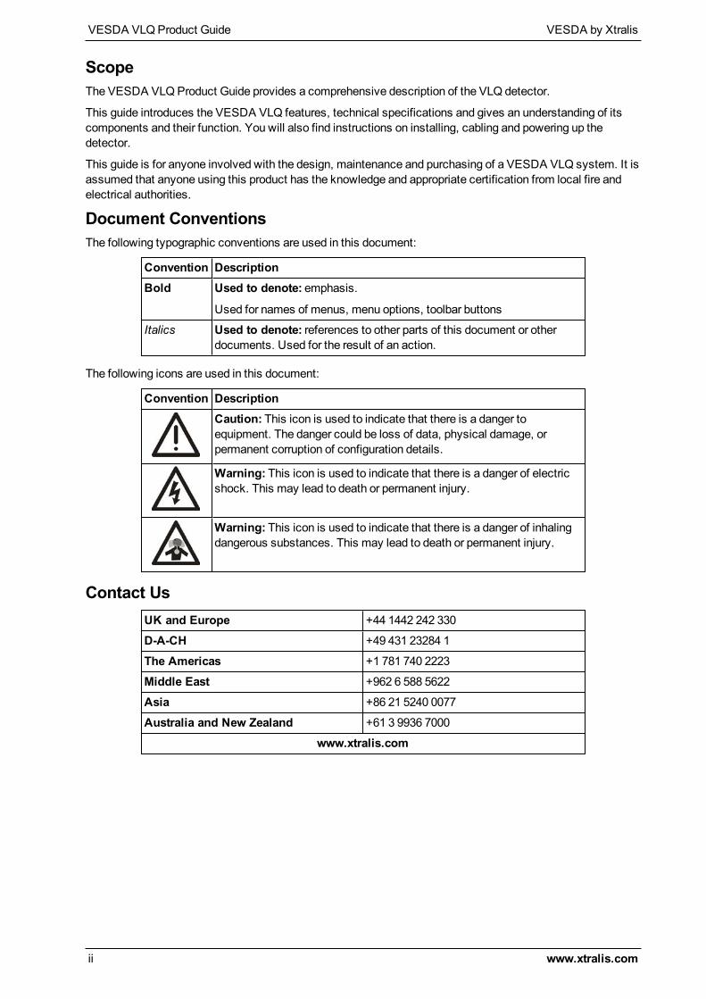
Convention DescriptionCaution: This icon is used to indicate that there is a danger toequipment. The danger could be loss of data, physical damage, orpermanent corruption of configuration details.
Warning: This icon is used to indicate that there is a danger of electricshock. This may lead to death or permanent injury.
Warning: This icon is used to indicate that there is a danger of inhalingdangerous substances. This may lead to death or permanent injury.
Contact UsUK and Europe +44 1442 242 330
D-A-CH +49 431 23284 1
The Americas +1 781 740 2223
Middle East +962 6 588 5622
Asia +86 21 5240 0077
Australia and New Zealand +61 3 9936 7000
www.xtralis.com
VESDA by Xtralis VESDA VLQProduct Guide
www.xtralis.com iii
Codes and Standards Information for Air Sampling Smoke DetectionWe strongly recommend that this document is read in conjunction with the appropriate local codes and standardsfor smoke detection and electrical connections. This document contains generic product information and somesections may not comply with all local codes and standards. In these cases, the local codes and standards musttake precedence. The information below was correct at time of printing but may now be out of date, check with yourlocal codes, standards and listings for the current restrictions.
FCC Compliance StatementThis equipment has been tested and found to comply with the limits for a Class B digital device, pursuant to part 15of the FCC Rules. These limits are designed to provide reasonable protection against harmful interference in aresidential installation. This equipment generates, uses and can radiate radio frequency energy and, if not installedand used in accordance with the instruction, may cause harmful interference to radio communications. However,there is no guarantee that interference will not occur in a particular installation. If this equipment does causeharmful interference to radio or television reception, the user is encouraged to try to correct the interference by oneor more of the following measures; re-orientate or relocate the receiving antenna, increase the separation betweenthe equipment and receiver, connect the equipment to a power outlet which is on a different power circuit to thereceiver or consult the dealer or an experienced radio/television technician for help.
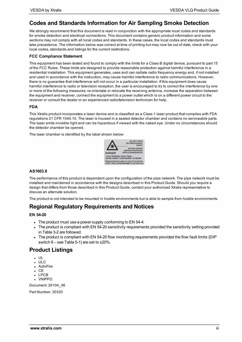
FDAThis Xtralis product incorporates a laser device and is classified as a Class 1 laser product that complies with FDAregulations 21 CFR 1040.10. The laser is housed in a sealed detector chamber and contains no serviceable parts.The laser emits invisible light and can be hazardous if viewed with the naked eye. Under no circumstances shouldthe detector chamber be opened.
The laser chamber is identified by the label shown below:
DANGER
DO NOT OPENNO SERVICEABLE
PARTS
Laser Radiation when OpenAVOID DIRECT EXPOSURE TO BEAM
NE PAS OUVRIRDISPOSITIFS/PIECES
NON ECHANGEABLES
Rayonnement Laser en cas d’ouvertureEVITEZ TOUTE EXPOSITION DIRECTE AU FAISCEAU
AS1603.8The performance of this product is dependent upon the configuration of the pipe network. The pipe network must beinstalled and maintained in accordance with the designs described in this Product Guide. Should you require adesign that differs from those described in this Product Guide, contact your authorized Xtralis representative todiscuss an alternate solution.
The product is not intended to be mounted in hostile environments but is able to sample from hostile environments.
Regional Regulatory Requirements and NoticesEN 54-20
l The product must use a power supply conforming to EN 54-4.l The product is compliant with EN 54-20 sensitivity requirements provided the sensitivity setting providedin Table 3-2 are followed.
l The product is compliant with EN 54-20 flow monitoring requirements provided the flow fault limits (DIPswitch 8 – see Table 5-1) are set to ±20%.
Product Listingsl ULl ULCl ActivFirel CEl LPCBl VNIPPO
Document: 26104_06
Part Number: 30320
VESDA VLQProduct Guide VESDA by Xtralis
iv www.xtralis.com
This page is intentionally left blank.
VESDA by Xtralis VESDA VLQProduct Guide
www.xtralis.com 1
Table of Contents1 Introduction 3
1.1 Features 4
2 Product Information 52.1 How it Works 52.2 Detector Overview 62.3 Specifications 92.4 Dimensions 11
3 Air Sampling Pipe Network 133.1 Installation Considerations 133.2 Pipe Inlets 133.3 Exhaust Air 133.4 Air Sampling Configurations 14
4 Installation 174.1 Mounting 184.2 Wiring 244.3 Specify Backup Battery for Power Supply 274.4 Installation Checklist 284.5 Powering Up 294.6 Preliminary System Check 29
5 Configuration 315.1 Logging on using the Display Panel 315.2 Setting the time using the Display Panel 315.3 DIP Switch Configuration 32
6 Commissioning 336.1 AutoLearn Smoke 336.2 Commissioning Smoke Test 33
7 Xtralis QSC Software 357.1 Installation 357.2 Functions 357.3 Configuration 367.4 Device Information 377.5 Test Functions 37
8 Maintenance 398.1 Replacing the Filter 39
9 Troubleshooting 439.1 Fault Codes 43

VESDA VLQProduct Guide VESDA by Xtralis
2 www.xtralis.com
This page is intentionally left blank.
VESDA by Xtralis VESDA VLQProduct Guide
www.xtralis.com 3
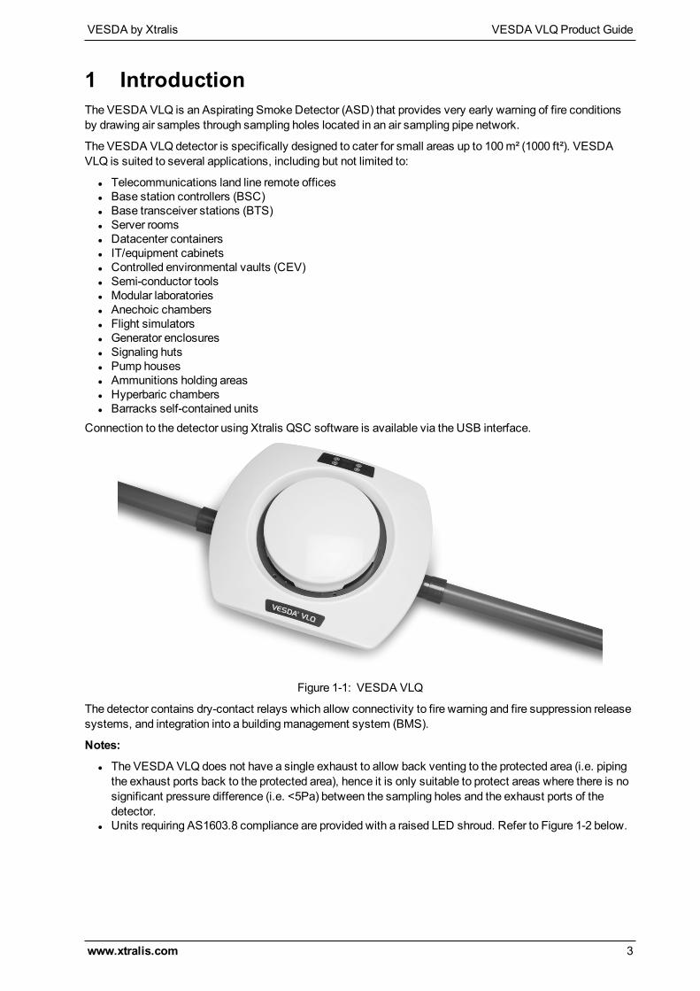
1 IntroductionThe VESDA VLQ is an Aspirating Smoke Detector (ASD) that provides very early warning of fire conditionsby drawing air samples through sampling holes located in an air sampling pipe network.
The VESDA VLQ detector is specifically designed to cater for small areas up to 100 m² (1000 ft²). VESDAVLQ is suited to several applications, including but not limited to:
l Telecommunications land line remote officesl Base station controllers (BSC)l Base transceiver stations (BTS)l Server roomsl Datacenter containersl IT/equipment cabinetsl Controlled environmental vaults (CEV)l Semi-conductor toolsl Modular laboratoriesl Anechoic chambersl Flight simulatorsl Generator enclosuresl Signaling hutsl Pump housesl Ammunitions holding areasl Hyperbaric chambersl Barracks self-contained units
Connection to the detector using Xtralis QSC software is available via the USB interface.
Figure 1-1: VESDA VLQ
The detector contains dry-contact relays which allow connectivity to fire warning and fire suppression releasesystems, and integration into a buildingmanagement system (BMS).
Notes:
l The VESDA VLQ does not have a single exhaust to allow back venting to the protected area (i.e. pipingthe exhaust ports back to the protected area), hence it is only suitable to protect areas where there is nosignificant pressure difference (i.e. <5Pa) between the sampling holes and the exhaust ports of thedetector.
l Units requiring AS1603.8 compliance are provided with a raised LED shroud. Refer to Figure 1-2 below.
VESDA VLQProduct Guide VESDA by Xtralis
4 www.xtralis.com
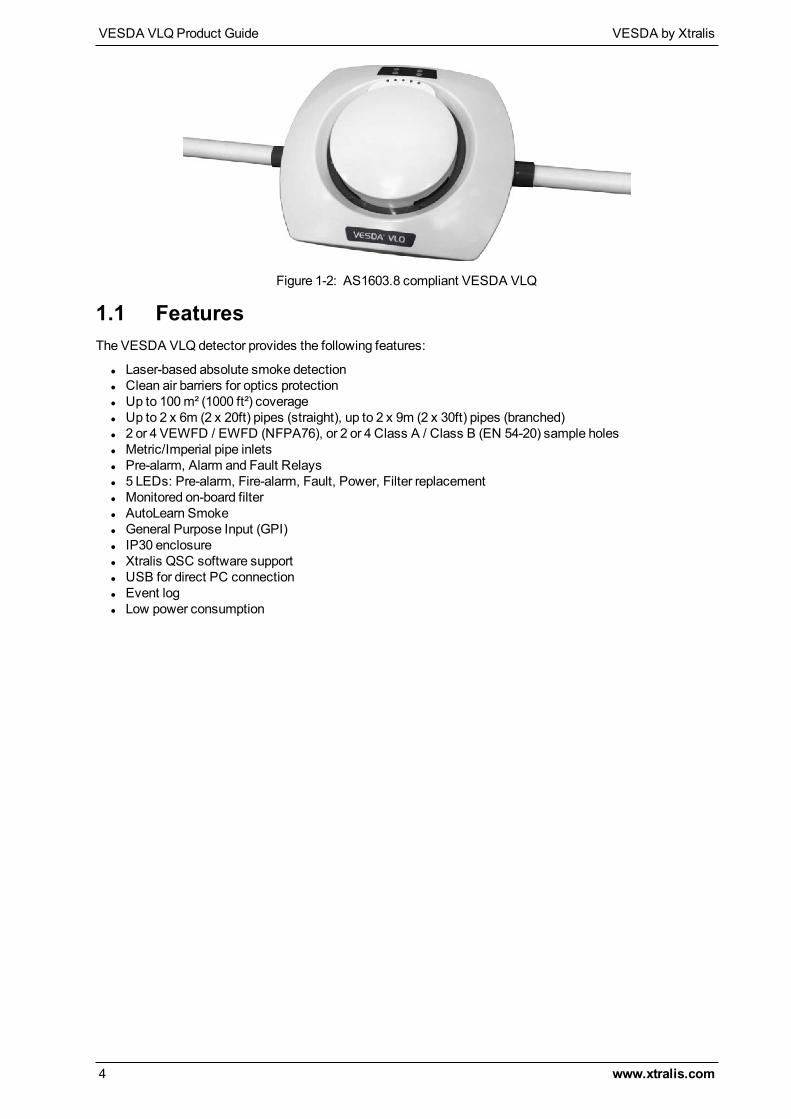
Figure 1-2: AS1603.8 compliant VESDA VLQ
1.1 FeaturesThe VESDA VLQ detector provides the following features:
l Laser-based absolute smoke detectionl Clean air barriers for optics protectionl Up to 100m² (1000 ft²) coveragel Up to 2 x 6m (2 x 20ft) pipes (straight), up to 2 x 9m (2 x 30ft) pipes (branched)l 2 or 4 VEWFD / EWFD (NFPA76), or 2 or 4 Class A / Class B (EN 54-20) sample holesl Metric/Imperial pipe inletsl Pre-alarm, Alarm and Fault Relaysl 5 LEDs: Pre-alarm, Fire-alarm, Fault, Power, Filter replacementl Monitored on-board filterl AutoLearn Smokel General Purpose Input (GPI)l IP30 enclosurel Xtralis QSC software supportl USB for direct PC connectionl Event logl Low power consumption
VESDA by Xtralis VESDA VLQProduct Guide
www.xtralis.com 5
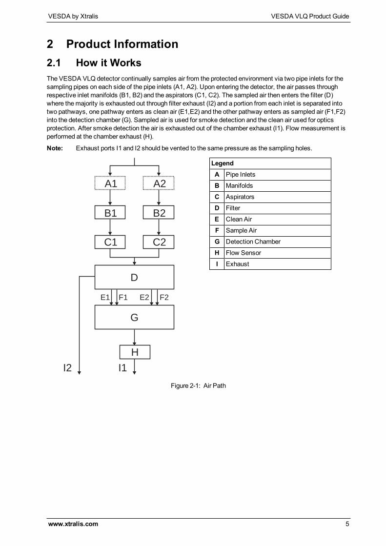
2 Product Information2.1 How it WorksThe VESDA VLQ detector continually samples air from the protected environment via two pipe inlets for thesampling pipes on each side of the pipe inlets (A1, A2). Upon entering the detector, the air passes throughrespective inlet manifolds (B1, B2) and the aspirators (C1, C2). The sampled air then enters the filter (D)where themajority is exhausted out through filter exhaust (I2) and a portion from each inlet is separated intotwo pathways, one pathway enters as clean air (E1,E2) and the other pathway enters as sampled air (F1,F2)into the detection chamber (G). Sampled air is used for smoke detection and the clean air used for opticsprotection. After smoke detection the air is exhausted out of the chamber exhaust (I1). Flow measurement isperformed at the chamber exhaust (H).
Note: Exhaust ports I1 and I2 should be vented to the same pressure as the sampling holes.
I2 I1
D
G
E1 F2
B1
A1
B2
A2
C1 C2
F1 E2
H
LegendA Pipe Inlets
B Manifolds
C Aspirators
D Filter
E Clean Air
F Sample Air
G Detection Chamber
H Flow Sensor
I Exhaust
Figure 2-1: Air Path
VESDA VLQProduct Guide VESDA by Xtralis
6 www.xtralis.com
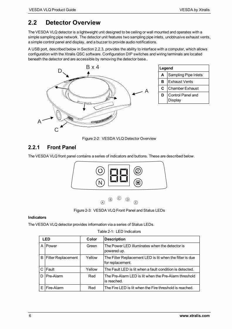
2.2 Detector OverviewThe VESDA VLQ detector is a lightweight unit designed to be ceiling or wall mounted and operates with asimple sampling pipe network. The detector unit features two sampling pipe inlets, unobtrusive exhaust vents,a simple control panel and display, and a buzzer to provide audio notifications.
A USB port, described below in Section 2.2.3, provides the ability to interface with a computer, which allowsconfiguration with the Xtralis QSC software. Configuration DIP switches and wiring terminals are locatedbeneath the detector and are accessible by removing the detector base..
A
A
C
DB x 4 Legend
A Sampling Pipe Inlets
B Exhaust Vents
C Chamber Exhaust
D Control Panel andDisplay
Figure 2-2: VESDA VLQDetector Overview
2.2.1 Front PanelThe VESDA VLQ front panel contains a series of indicators and buttons. These are described below.
88
A
BC
D
E
Figure 2-3: VESDA VLQ Front Panel and Status LEDs
Indicators
The VESDA VLQ detector provides information via a series of Status LEDs.
LED Color DescriptionA Power Green The Power LED illuminates when the detector is
powered up.
B Filter Replacement Yellow The Filter Replacement LED is lit when the filter is duefor replacement.
C Fault Yellow The Fault LED is lit when a fault condition is detected.
D Pre-Alarm Red The Pre-Alarm LED is lit when the Pre-Alarm thresholdis reached.
E Fire-Alarm Red The Fire LED is lit when the Fire threshold is reached.
Table 2-1: LED Indicators
VESDA by Xtralis VESDA VLQProduct Guide
www.xtralis.com 7
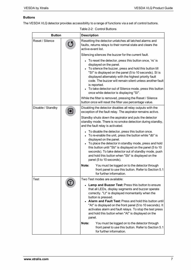
Buttons
The VESDA VLQ detector provides accessibility to a range of functions via a set of control buttons.
Button DescriptionReset / Silence Resetting the detector unlatches all latched alarms and
faults, returns relays to their normal state and clears theactive event list.
Silencing silences the buzzer for the current fault.
l To reset the detector, press this button once, 'rs' isdisplayed on the panel.
l To silence the buzzer, press and hold this button till"SI" is displayed on the panel (5 to 10 seconds). SI isdisplayed alternately with the highest priority faultcode. The buzzer will remain silent unless another faultis reported.
l To take detector out of Silencemode, press this buttononce while detector is displaying "SI".
While the filter is removed, pressing the Reset / Silencebutton once will reset the filter use percentage value.
Disable / Standby Disabling the detector disables all relay outputs with theexception of the fault relay. The aspirator remains active.
Standby shuts down the aspirator and puts the detectorstandby mode. There is no smoke detection during standby,and the fault relay is activated.
l To disable the detector, press this button once.l To re-enable the unit, press the button while "db" isdisplayed on the panel.
l To place the detector in standby mode, press and holdthis button until "Sb" is displayed on the panel (5 to 10seconds). To take detector out of standby mode, pushand hold this button when "Sb" is displayed on thepanel (5 to 10 seconds).
Note: Youmust be logged on to the detector throughfront panel to use this button. Refer to Section 5.1for further information.
Test Two Test modes are available:
l Lamp and Buzzer Test:Press this button to ensurethat all LEDs, display segments and buzzer operatecorrectly. "Lt" is displayedmomentarily when thebutton is pressed.
l Alarm and Fault Test:Press and hold this button until"At" is displayed on the front panel (5 to 10 seconds). Itactivates alarm and fault relays. To stop the test pressand hold this button when "At" is displayed on thepanel.
Note: Youmust be logged on to the detector throughfront panel to use this button. Refer to Section 5.1for further information.
Table 2-2: Control Buttons
VESDA VLQProduct Guide VESDA by Xtralis
8 www.xtralis.com
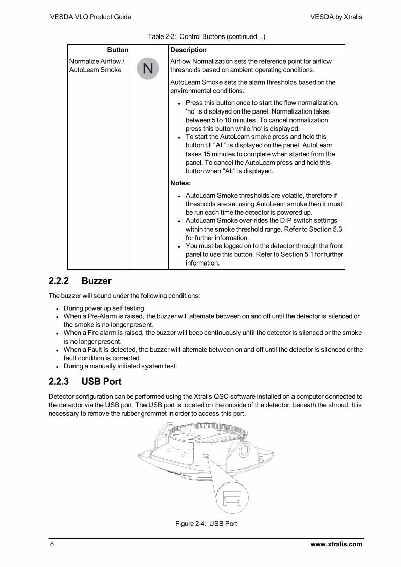
Button DescriptionNormalize Airflow /AutoLearn Smoke
Airflow Normalization sets the reference point for airflowthresholds based on ambient operating conditions.
AutoLearn Smoke sets the alarm thresholds based on theenvironmental conditions.
l Press this button once to start the flow normalization,'no' is displayed on the panel. Normalization takesbetween 5 to 10minutes. To cancel normalizationpress this button while 'no' is displayed.
l To start the AutoLearn smoke press and hold thisbutton till "AL" is displayed on the panel. AutoLearntakes 15minutes to complete when started from thepanel. To cancel the AutoLearn press and hold thisbutton when "AL" is displayed.
Notes:
l AutoLearn Smoke thresholds are volatile, therefore ifthresholds are set using AutoLearn smoke then it mustbe run each time the detector is powered up.
l AutoLearn Smoke over-rides the DIP switch settingswithin the smoke threshold range. Refer to Section 5.3for further information.
l Youmust be logged on to the detector through the frontpanel to use this button. Refer to Section 5.1 for furtherinformation.
Table 2-2: Control Buttons (continued...)
2.2.2 BuzzerThe buzzer will sound under the following conditions:
l During power up self testing.l When a Pre-Alarm is raised, the buzzer will alternate between on and off until the detector is silenced orthe smoke is no longer present.
l When a Fire alarm is raised, the buzzer will beep continuously until the detector is silenced or the smokeis no longer present.
l When a Fault is detected, the buzzer will alternate between on and off until the detector is silenced or thefault condition is corrected.
l During amanually initiated system test.
2.2.3 USB PortDetector configuration can be performed using the Xtralis QSC software installed on a computer connected tothe detector via the USB port. The USB port is located on the outside of the detector, beneath the shroud. It isnecessary to remove the rubber grommet in order to access this port.
Figure 2-4: USB Port
VESDA by Xtralis VESDA VLQProduct Guide
www.xtralis.com 9
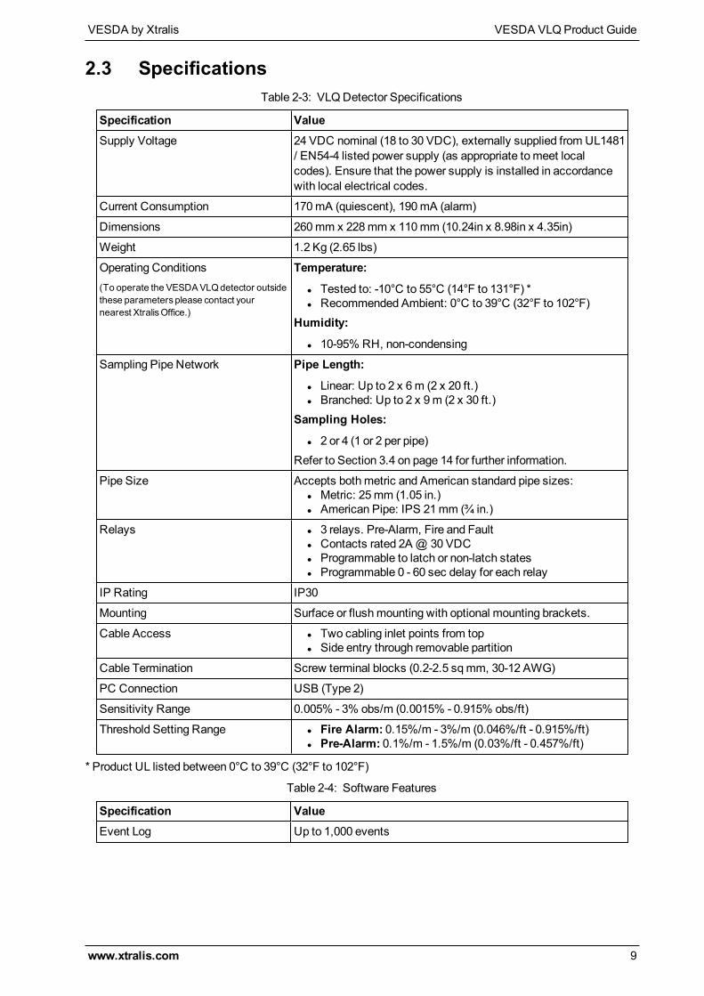
2.3 Specifications
Specification ValueSupply Voltage 24 VDC nominal (18 to 30 VDC), externally supplied from UL1481
/ EN54-4 listed power supply (as appropriate tomeet localcodes). Ensure that the power supply is installed in accordancewith local electrical codes.
Current Consumption 170mA (quiescent), 190mA (alarm)
Dimensions 260mm x 228mm x 110mm (10.24in x 8.98in x 4.35in)
Weight 1.2 Kg (2.65 lbs)
Operating Conditions(To operate the VESDAVLQdetector outsidethese parameters please contact yournearest XtralisOffice.)
Temperature:
l Tested to: -10°C to 55°C (14°F to 131°F) *l Recommended Ambient: 0°C to 39°C (32°F to 102°F)
Humidity:
l 10-95% RH, non-condensing
Sampling Pipe Network Pipe Length:
l Linear: Up to 2 x 6m (2 x 20 ft.)l Branched: Up to 2 x 9m (2 x 30 ft.)
Sampling Holes:
l 2 or 4 (1 or 2 per pipe)Refer to Section 3.4 on page 14 for further information.
Pipe Size Accepts bothmetric and American standard pipe sizes:l Metric: 25mm (1.05 in.)l American Pipe: IPS 21mm (¾ in.)
Relays l 3 relays. Pre-Alarm, Fire and Faultl Contacts rated 2A@ 30 VDCl Programmable to latch or non-latch statesl Programmable 0 - 60 sec delay for each relay
IP Rating IP30
Mounting Surface or flushmounting with optional mounting brackets.
Cable Access l Two cabling inlet points from topl Side entry through removable partition
Cable Termination Screw terminal blocks (0.2-2.5 sqmm, 30-12 AWG)
PC Connection USB (Type 2)
Sensitivity Range 0.005% - 3% obs/m (0.0015% - 0.915% obs/ft)
Threshold Setting Range l Fire Alarm: 0.15%/m - 3%/m (0.046%/ft - 0.915%/ft)l Pre-Alarm: 0.1%/m - 1.5%/m (0.03%/ft - 0.457%/ft)
Table 2-3: VLQDetector Specifications
* Product UL listed between 0°C to 39°C (32°F to 102°F)
Specification ValueEvent Log Up to 1,000 events
Table 2-4: Software Features

VESDA VLQProduct Guide VESDA by Xtralis
10 www.xtralis.com
Specification ValueAutoLearn Smoke l Minimum: 15minutes
l Maximum: 2 Hours (through Xtralis QSC)l Recommended minimum period: 1 hour
Thresholds are automatically changed from the previously setvalues to the updated values after the AutoLearn process hascompleted. AutoLearn Smoke over-rides the DIP switch settingswithin the smoke threshold range.
Maintenance Aids l Event logl Smoke log
Table 2-4: Software Features (continued...)
2.3.1 Ordering Information
Part Number DescriptionVLQ-100 Detector
VSP-890 SurfaceMount Kit
VSP-891 FlushMount Kit
VSP-892 Replacement Filter
VSP-892-20 Replacement Filter - 20 pieces
VSP-893 Pipe Kit (Metric)
VSP-893-US Pipe Kit (Imperial)
Table 2-5: Ordering Information
VESDA by Xtralis VESDA VLQProduct Guide
www.xtralis.com 11
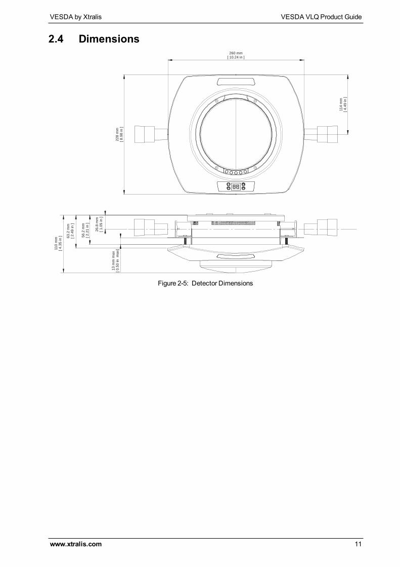
2.4 Dimensions260 mm
[ 10.24 in ]
11
4 m
m
[ 4
.49
in
]
22
8 m
m
[ 8
.98
in
]
26
.8 m
m
[ 1
.05
in
]
11
0 m
m
[ 4
.35
in
] 63
.2 m
m
[ 2
.49
in
]
13
mm
ma
x
[ 0
.50
in
m
ax]
56
.2 m
m
[ 2
.21
in
]
Figure 2-5: Detector Dimensions

VESDA VLQProduct Guide VESDA by Xtralis
12 www.xtralis.com
This page is intentionally left blank.
VESDA by Xtralis VESDA VLQProduct Guide
www.xtralis.com 13
3 Air Sampling Pipe NetworkThe detector uses two linear pipes of up to 6m (20 ft) or two branched pipes of up to 9m (30ft) to cover amaximum of 100m² (1000 ft²). Short pipes can be used to suit the installation.
3.1 Installation ConsiderationsThe following points should be considered when installing sampling pipe:
l Minimize flexing in sampling pipes by supporting the pipe every 1.5m (5 ft) or less, or at a distancedescribed in local codes and standards.
l Sampling pipe fits firmly into the tapered detector port, DONOT glue this connection.l Allow sufficient movement at the detector to permit pipe removal for maintenance.l Pipe ends must bemade smooth for bonding.l Sampling holes must be drilled in line and perpendicular to the pipe.l Sample holes must be clear of rough edges and debris.l Ensure that all sampling holes are from within a single space (not physically different areas separated bywalls).
l Ensure that there is no significant pressure differential between sampling holes and exhaust ports.l Pipes are free of debris.l All joints must be glued except the pipes entering the detector.
Notes:
l Sampling holes should face into the direction of airflow, or point downwards in static airflow situations.For return air sampling refer to the notes in Section 3.4 on page 14.
l For code-specific information, see Codes and Standards Information for Air Sampling Smoke Detectionon page iii.
3.2 Pipe InletsThe VESDA VLQ detector supports two sampling pipes. Both pipes must be connected for proper detectoroperation.
The air inlet ports are tapered such that they accommodate both 25mm (1 in) or IPS ¾ inch (1.05 in outerdiameter) pipes. Each air inlet port allows maximum insertion of the sampling pipe to a depth of 15mm (0.60in).
While connecting the detector to the pipe network:
l Square off and de-burr the end of the sampling air pipes, ensuring the pipes are free from debris.l Insert the pipes into the pipe inlet(s) ensuring a firm fit.
Note: DONOT glue the pipes to the pipe inlets.
3.3 Exhaust AirAir is expelled from the detector via the filter and after the detection chamber into the area where the detectoris located. Refer to Figure 2-2 on page 6.
There should be no significant pressure differential between the sampling holes and the exhaust ports.
VESDA VLQProduct Guide VESDA by Xtralis
14 www.xtralis.com
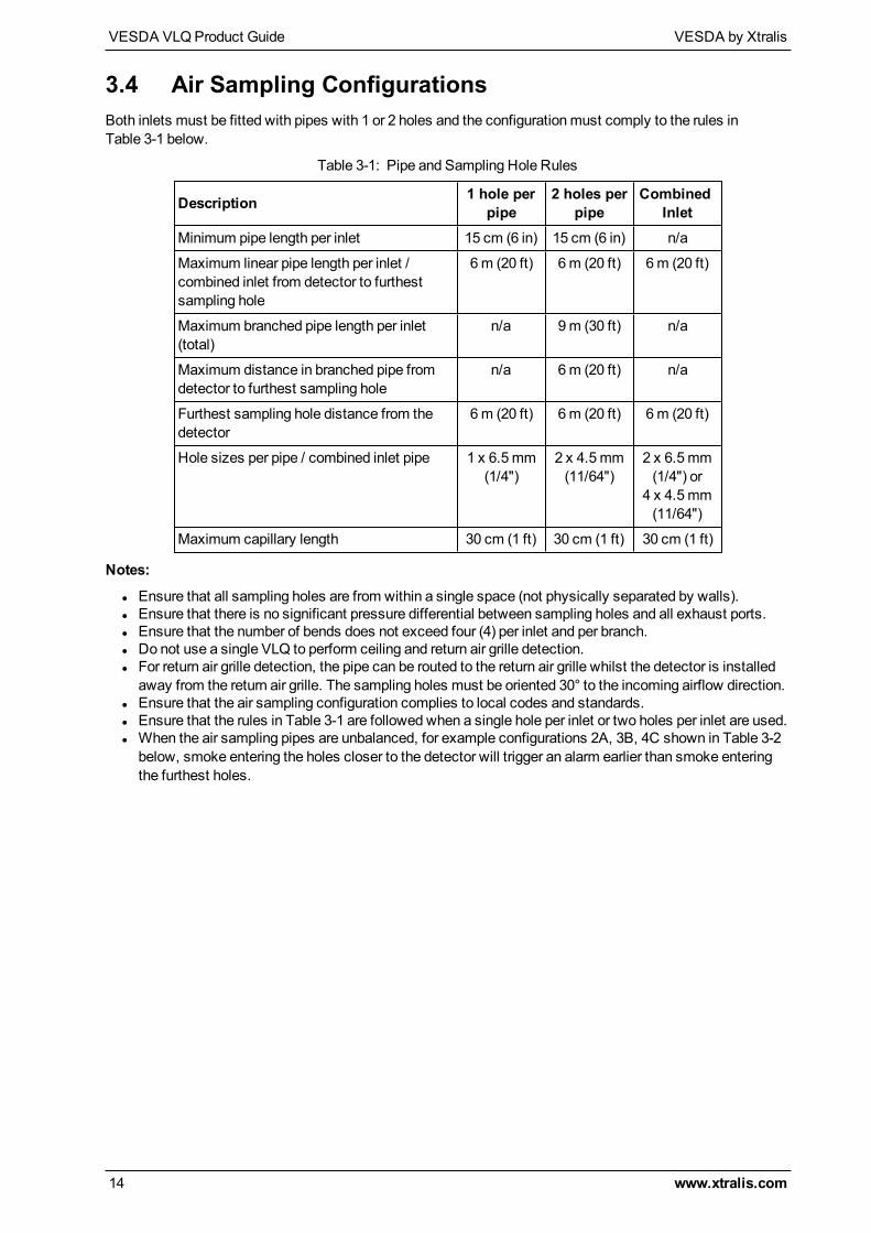
3.4 Air Sampling ConfigurationsBoth inlets must be fitted with pipes with 1 or 2 holes and the configurationmust comply to the rules inTable 3-1 below.
Description 1 hole perpipe
2 holes perpipe
CombinedInlet
Minimum pipe length per inlet 15 cm (6 in) 15 cm (6 in) n/a
Maximum linear pipe length per inlet /combined inlet from detector to furthestsampling hole
6m (20 ft) 6 m (20 ft) 6 m (20 ft)
Maximum branched pipe length per inlet(total)
n/a 9m (30 ft) n/a
Maximum distance in branched pipe fromdetector to furthest sampling hole
n/a 6m (20 ft) n/a
Furthest sampling hole distance from thedetector
6m (20 ft) 6 m (20 ft) 6 m (20 ft)
Hole sizes per pipe / combined inlet pipe 1 x 6.5mm(1/4")
2 x 4.5mm(11/64")
2 x 6.5mm(1/4") or
4 x 4.5mm(11/64")
Maximum capillary length 30 cm (1 ft) 30 cm (1 ft) 30 cm (1 ft)
Table 3-1: Pipe and Sampling Hole Rules
Notes:
l Ensure that all sampling holes are from within a single space (not physically separated by walls).l Ensure that there is no significant pressure differential between sampling holes and all exhaust ports.l Ensure that the number of bends does not exceed four (4) per inlet and per branch.l Do not use a single VLQ to perform ceiling and return air grille detection.l For return air grille detection, the pipe can be routed to the return air grille whilst the detector is installedaway from the return air grille. The sampling holes must be oriented 30° to the incoming airflow direction.
l Ensure that the air sampling configuration complies to local codes and standards.l Ensure that the rules in Table 3-1 are followed when a single hole per inlet or two holes per inlet are used.l When the air sampling pipes are unbalanced, for example configurations 2A, 3B, 4C shown in Table 3-2below, smoke entering the holes closer to the detector will trigger an alarm earlier than smoke enteringthe furthest holes.
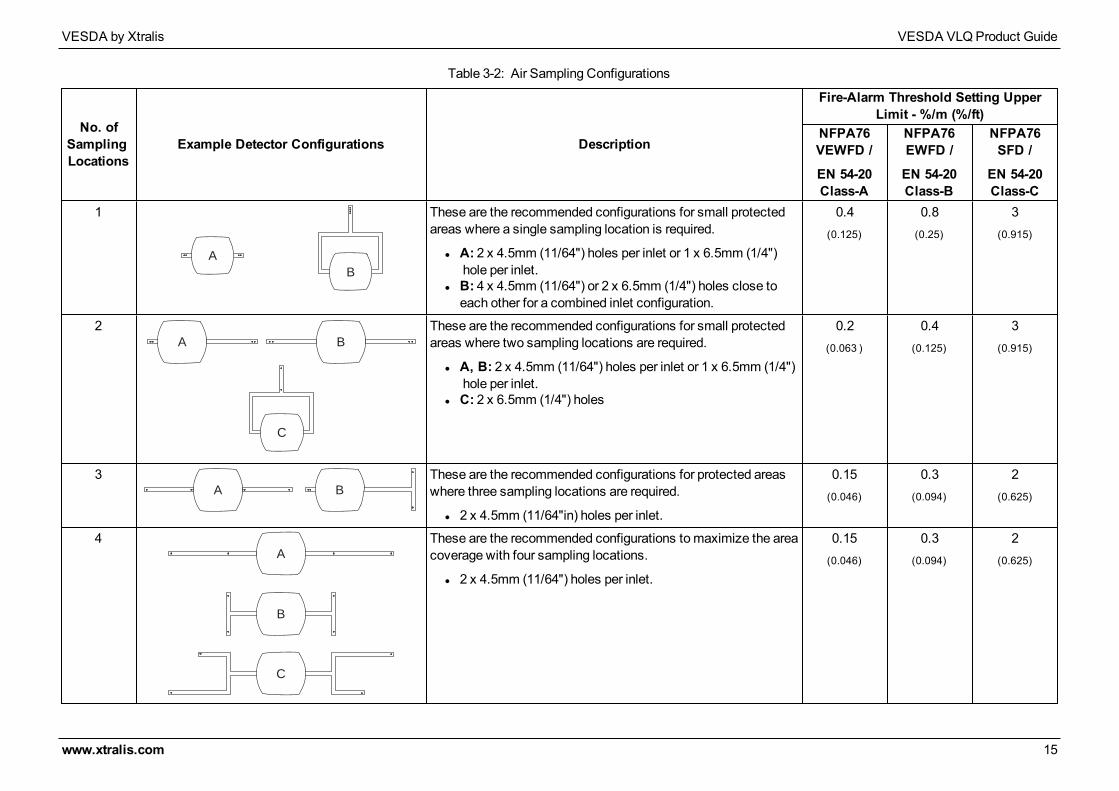
No. ofSamplingLocations
Example Detector Configurations Description
Fire-Alarm Threshold Setting UpperLimit - %/m (%/ft)
NFPA76VEWFD /
EN 54-20Class-A
NFPA76EWFD /
EN 54-20Class-B
NFPA76SFD /
EN 54-20Class-C
1
A
B
These are the recommended configurations for small protectedareas where a single sampling location is required.
l A: 2 x 4.5mm (11/64") holes per inlet or 1 x 6.5mm (1/4") hole per inlet.
l B: 4 x 4.5mm (11/64") or 2 x 6.5mm (1/4") holes close toeach other for a combined inlet configuration.
0.4(0.125)
0.8(0.25)
3(0.915)
2A B
C
These are the recommended configurations for small protectedareas where two sampling locations are required.
l A, B: 2 x 4.5mm (11/64") holes per inlet or 1 x 6.5mm (1/4") hole per inlet.
l C: 2 x 6.5mm (1/4") holes
0.2(0.063 )
0.4(0.125)
3(0.915)
3A B
These are the recommended configurations for protected areaswhere three sampling locations are required.
l 2 x 4.5mm (11/64"in) holes per inlet.
0.15(0.046)
0.3(0.094)
2(0.625)
4A
B
C
These are the recommended configurations tomaximize the areacoverage with four sampling locations.
l 2 x 4.5mm (11/64") holes per inlet.
0.15(0.046)
0.3(0.094)
2(0.625)
Table 3-2: Air Sampling Configurations
VESDA by Xtralis VESDA VLQProduct Guide
www.xtralis.com 15

VESDA VLQProduct Guide VESDA by Xtralis
16 www.xtralis.com
This page is intentionally left blank.
VESDA by Xtralis VESDA VLQProduct Guide
www.xtralis.com 17
4 InstallationThe VESDA VLQ detector is shipped with the following components:
l VESDA VLQ detector, including basel FlushMount or SurfaceMount bracket kits (ordered separately)l Stub pipes and end caps (ordered separately)
Check all components for damage and refer any concerns to your authorized representative.
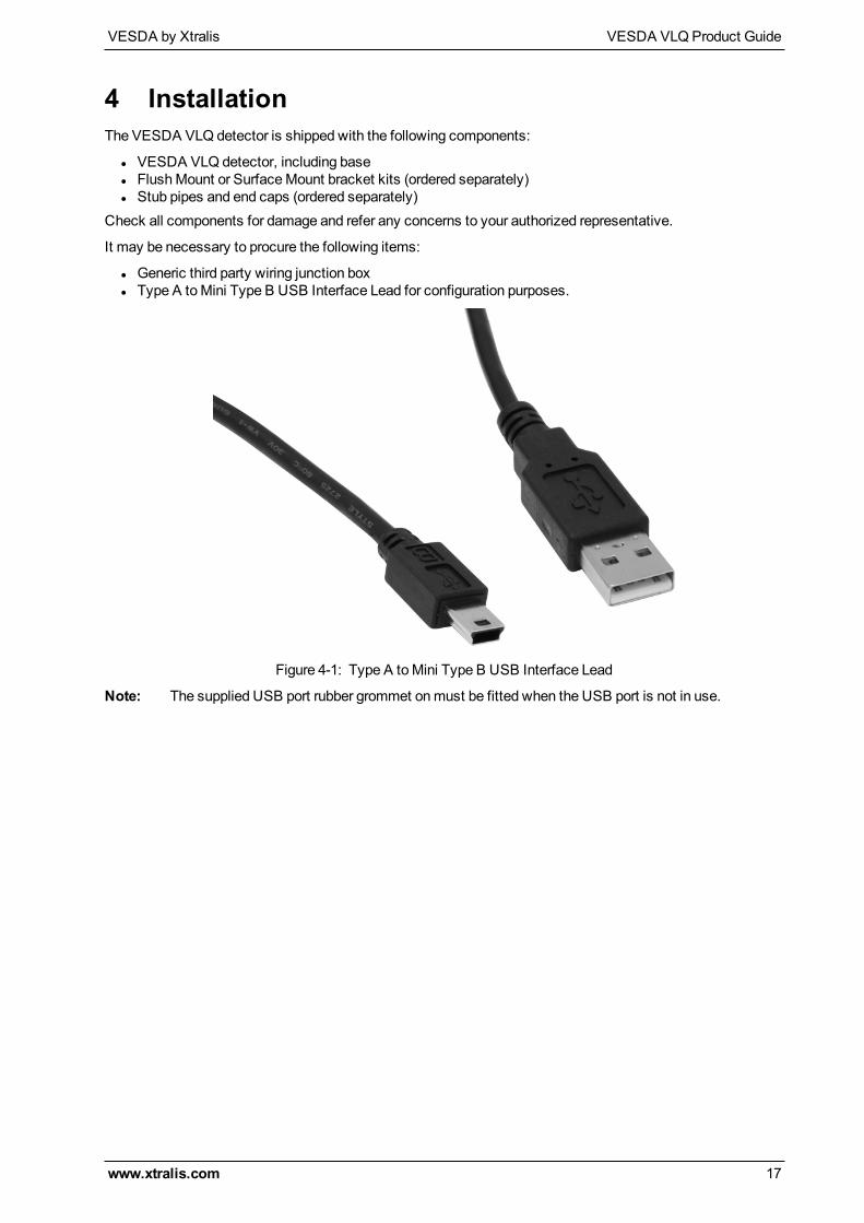
It may be necessary to procure the following items:
l Generic third party wiring junction boxl Type A toMini Type B USB Interface Lead for configuration purposes.
Figure 4-1: Type A toMini Type B USB Interface Lead
Note: The supplied USB port rubber grommet onmust be fitted when the USB port is not in use.
VESDA VLQProduct Guide VESDA by Xtralis
18 www.xtralis.com
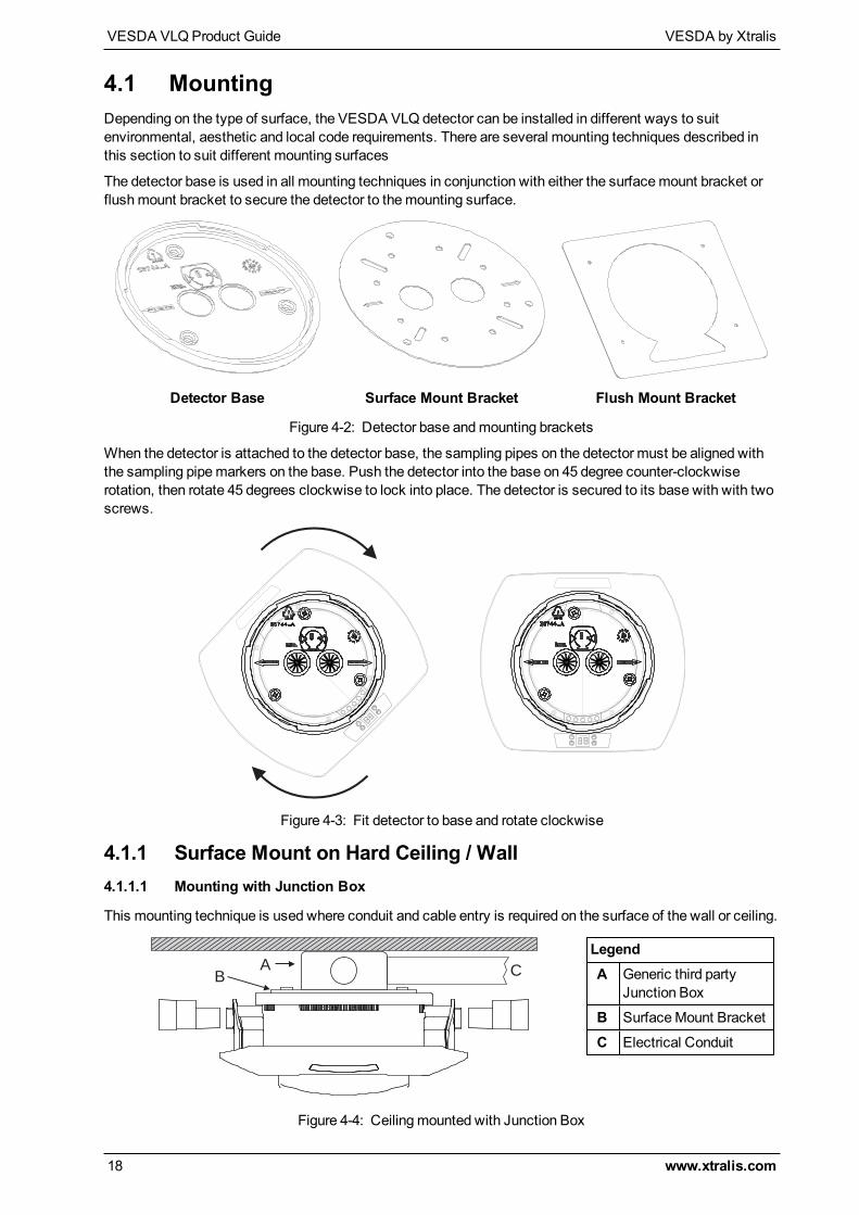
4.1 MountingDepending on the type of surface, the VESDA VLQ detector can be installed in different ways to suitenvironmental, aesthetic and local code requirements. There are several mounting techniques described inthis section to suit different mounting surfaces
The detector base is used in all mounting techniques in conjunction with either the surfacemount bracket orflushmount bracket to secure the detector to themounting surface.
Detector Base Surface Mount Bracket Flush Mount Bracket
Figure 4-2: Detector base andmounting brackets
When the detector is attached to the detector base, the sampling pipes on the detector must be aligned withthe sampling pipemarkers on the base. Push the detector into the base on 45 degree counter-clockwiserotation, then rotate 45 degrees clockwise to lock into place. The detector is secured to its base with with twoscrews.
Figure 4-3: Fit detector to base and rotate clockwise
4.1.1 Surface Mount on Hard Ceiling / Wall4.1.1.1 Mounting with Junction Box
This mounting technique is used where conduit and cable entry is required on the surface of the wall or ceiling.
AB
C
LegendA Generic third party
Junction Box
B SurfaceMount Bracket
C Electrical Conduit
Figure 4-4: Ceilingmounted with Junction Box
VESDA by Xtralis VESDA VLQProduct Guide
www.xtralis.com 19
1. Secure the Junction Box (A) to the hard surface with appropriate fasteners.2. Connect wiring conduit (C) to Junction Box and pass the wires through.3. Remove the detector base from the detector body by holding the detector body and rotating the base
anti-clockwise.4. Pass wires through the detector base and screw the detector base to the SurfaceMount Bracket (B).5. Screw the surfacemount bracket to the junction box and pass the wires through its holes, ensuring that
the sampling pipe inlet arrows on the surfacemount bracket are appropriately positioned.6. Feed wires through the wire retaining strip on the base of the detector and attach to the appropriate
terminal block connectors.7. Fit the terminal block connectors to the appropriate sockets on the terminal block.8. Align detector body to the base so that there is room to rotate it clockwise, ensuring that pipe inlets
match the arrows shown on the detector body.9. Insert pipes into the pipe inlets and seat them tightly.10. Use the suppliedM3x10 self tapping screws to secure the detector to the detector base where detector
base has two tabs to secure with the detector body.
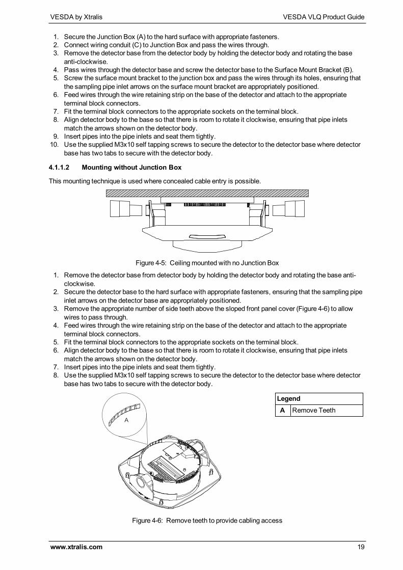
4.1.1.2 Mounting without Junction Box
This mounting technique is used where concealed cable entry is possible.
Figure 4-5: Ceilingmounted with no Junction Box
1. Remove the detector base from detector body by holding the detector body and rotating the base anti-clockwise.
2. Secure the detector base to the hard surface with appropriate fasteners, ensuring that the sampling pipeinlet arrows on the detector base are appropriately positioned.
3. Remove the appropriate number of side teeth above the sloped front panel cover (Figure 4-6) to allowwires to pass through.
4. Feed wires through the wire retaining strip on the base of the detector and attach to the appropriateterminal block connectors.
5. Fit the terminal block connectors to the appropriate sockets on the terminal block.6. Align detector body to the base so that there is room to rotate it clockwise, ensuring that pipe inlets
match the arrows shown on the detector body.7. Insert pipes into the pipe inlets and seat them tightly.8. Use the suppliedM3x10 self tapping screws to secure the detector to the detector base where detector
base has two tabs to secure with the detector body.
A
LegendA Remove Teeth
Figure 4-6: Remove teeth to provide cabling access
VESDA VLQProduct Guide VESDA by Xtralis
20 www.xtralis.com
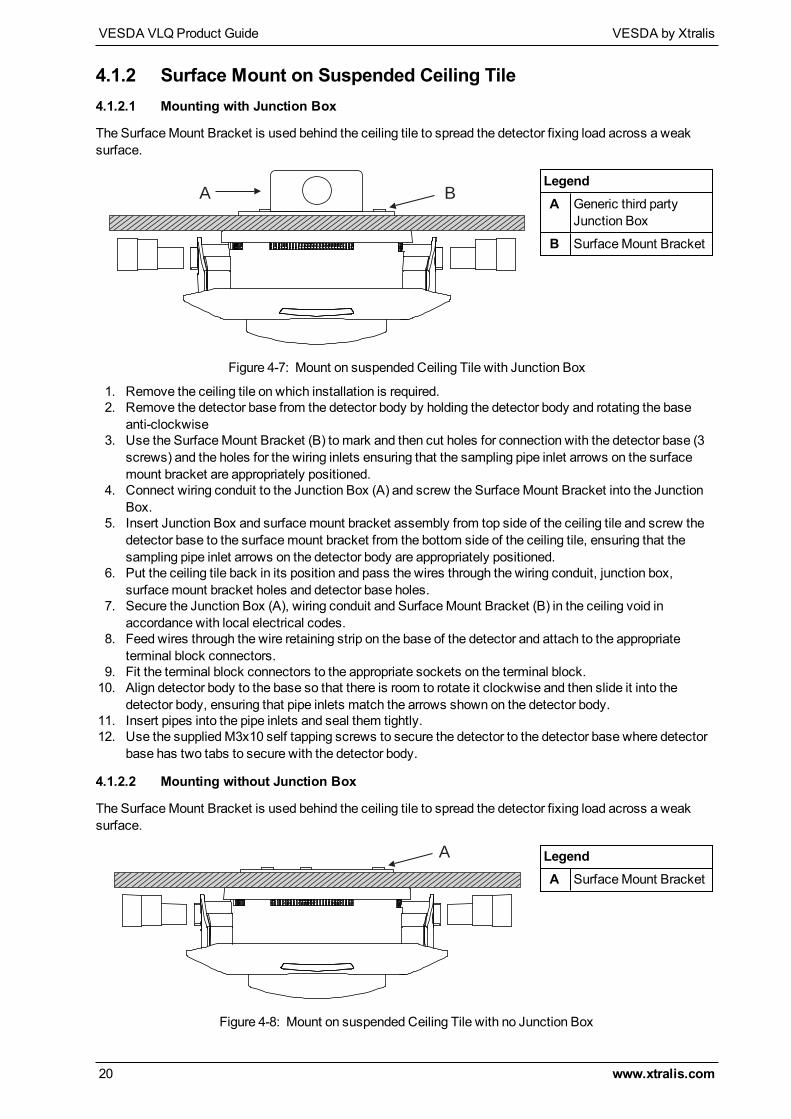
4.1.2 Surface Mount on Suspended Ceiling Tile4.1.2.1 Mounting with Junction Box
The SurfaceMount Bracket is used behind the ceiling tile to spread the detector fixing load across a weaksurface.
A BLegendA Generic third party
Junction Box
B SurfaceMount Bracket
Figure 4-7: Mount on suspended Ceiling Tile with Junction Box
1. Remove the ceiling tile on which installation is required.2. Remove the detector base from the detector body by holding the detector body and rotating the base
anti-clockwise3. Use the SurfaceMount Bracket (B) to mark and then cut holes for connection with the detector base (3
screws) and the holes for the wiring inlets ensuring that the sampling pipe inlet arrows on the surfacemount bracket are appropriately positioned.
4. Connect wiring conduit to the Junction Box (A) and screw the SurfaceMount Bracket into the JunctionBox.
5. Insert Junction Box and surfacemount bracket assembly from top side of the ceiling tile and screw thedetector base to the surfacemount bracket from the bottom side of the ceiling tile, ensuring that thesampling pipe inlet arrows on the detector body are appropriately positioned.
6. Put the ceiling tile back in its position and pass the wires through the wiring conduit, junction box,surfacemount bracket holes and detector base holes.
7. Secure the Junction Box (A), wiring conduit and SurfaceMount Bracket (B) in the ceiling void inaccordance with local electrical codes.
8. Feed wires through the wire retaining strip on the base of the detector and attach to the appropriateterminal block connectors.
9. Fit the terminal block connectors to the appropriate sockets on the terminal block.10. Align detector body to the base so that there is room to rotate it clockwise and then slide it into the
detector body, ensuring that pipe inlets match the arrows shown on the detector body.11. Insert pipes into the pipe inlets and seal them tightly.12. Use the suppliedM3x10 self tapping screws to secure the detector to the detector base where detector
base has two tabs to secure with the detector body.
4.1.2.2 Mounting without Junction Box
The SurfaceMount Bracket is used behind the ceiling tile to spread the detector fixing load across a weaksurface.
A LegendA SurfaceMount Bracket
Figure 4-8: Mount on suspended Ceiling Tile with no Junction Box
VESDA by Xtralis VESDA VLQProduct Guide
www.xtralis.com 21
1. Remove the ceiling tile on which installation is required.2. Remove the detector base from the detector body by holding the detector body and rotating the base
anti-clockwise.3. Use SurfaceMount Bracket (A) to drill threemounting holes and two wiring holes into the ceiling tile,
ensuring that the sampling pipe inlet arrows on the surfacemount bracket are appropriately positioned.4. Insert SurfaceMount Bracket from top side of the ceiling tile and screw the detector base into it from the
bottom side of the ceiling tile.5. Put the ceiling tile back in its position and pass the wires through the surfacemount bracket and detector
base holes.6. Secure the surfacemount bracket in the ceiling void in accordance with local electrical codes.7. Feed wires through the wire retaining strip on the base of the detector and attach to the appropriate
terminal block connectors.8. Fit the terminal block connectors to the appropriate sockets on the terminal block.9. Align detector body to the base so that there is room to rotate it clockwise, ensuring that pipe inlets
match the arrows shown on the detector body.10. Insert pipes into the pipe inlets and seal them tightly.11. Use the suppliedM3x10 self tapping screws to secure the detector to the detector base where detector
base has two tabs to secure with the detector body.
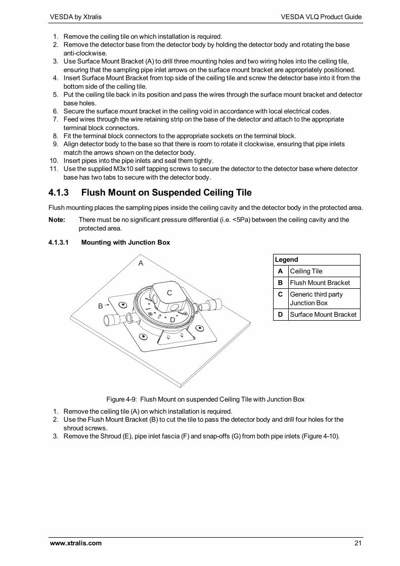
4.1.3 Flush Mount on Suspended Ceiling TileFlushmounting places the sampling pipes inside the ceiling cavity and the detector body in the protected area.
Note: Theremust be no significant pressure differential (i.e. <5Pa) between the ceiling cavity and theprotected area.
4.1.3.1 Mounting with Junction Box
C
A
B
D
LegendA Ceiling Tile
B FlushMount Bracket
C Generic third partyJunction Box
D SurfaceMount Bracket
Figure 4-9: FlushMount on suspended Ceiling Tile with Junction Box
1. Remove the ceiling tile (A) on which installation is required.2. Use the FlushMount Bracket (B) to cut the tile to pass the detector body and drill four holes for the
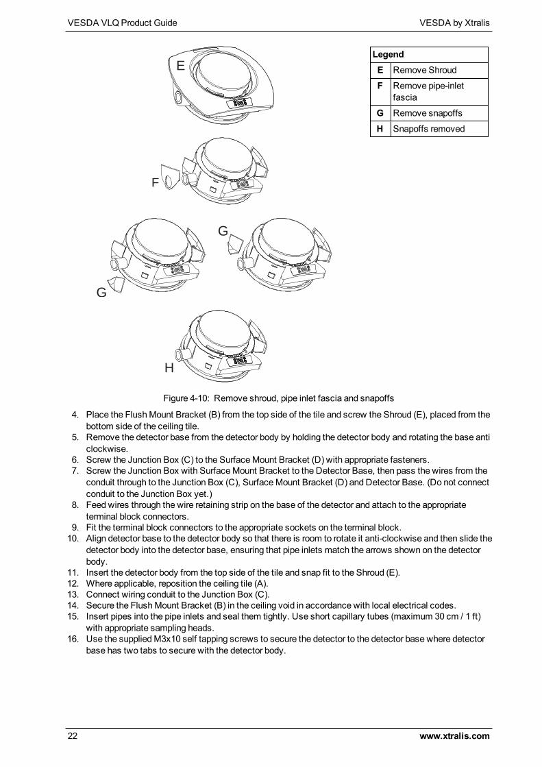
shroud screws.3. Remove the Shroud (E), pipe inlet fascia (F) and snap-offs (G) from both pipe inlets (Figure 4-10).
VESDA VLQProduct Guide VESDA by Xtralis
22 www.xtralis.com
E
LegendE Remove Shroud
F Remove pipe-inletfascia
G Remove snapoffs
H Snapoffs removed
F
G
G
H
Figure 4-10: Remove shroud, pipe inlet fascia and snapoffs
4. Place the FlushMount Bracket (B) from the top side of the tile and screw the Shroud (E), placed from thebottom side of the ceiling tile.
5. Remove the detector base from the detector body by holding the detector body and rotating the base anticlockwise.
6. Screw the Junction Box (C) to the SurfaceMount Bracket (D) with appropriate fasteners.7. Screw the Junction Box with SurfaceMount Bracket to the Detector Base, then pass the wires from the
conduit through to the Junction Box (C), SurfaceMount Bracket (D) and Detector Base. (Do not connectconduit to the Junction Box yet.)
8. Feed wires through the wire retaining strip on the base of the detector and attach to the appropriateterminal block connectors.
9. Fit the terminal block connectors to the appropriate sockets on the terminal block.10. Align detector base to the detector body so that there is room to rotate it anti-clockwise and then slide the
detector body into the detector base, ensuring that pipe inlets match the arrows shown on the detectorbody.
11. Insert the detector body from the top side of the tile and snap fit to the Shroud (E).12. Where applicable, reposition the ceiling tile (A).13. Connect wiring conduit to the Junction Box (C).14. Secure the FlushMount Bracket (B) in the ceiling void in accordance with local electrical codes.15. Insert pipes into the pipe inlets and seal them tightly. Use short capillary tubes (maximum 30 cm / 1 ft)
with appropriate sampling heads.16. Use the suppliedM3x10 self tapping screws to secure the detector to the detector base where detector
base has two tabs to secure with the detector body.
VESDA by Xtralis VESDA VLQProduct Guide
www.xtralis.com 23
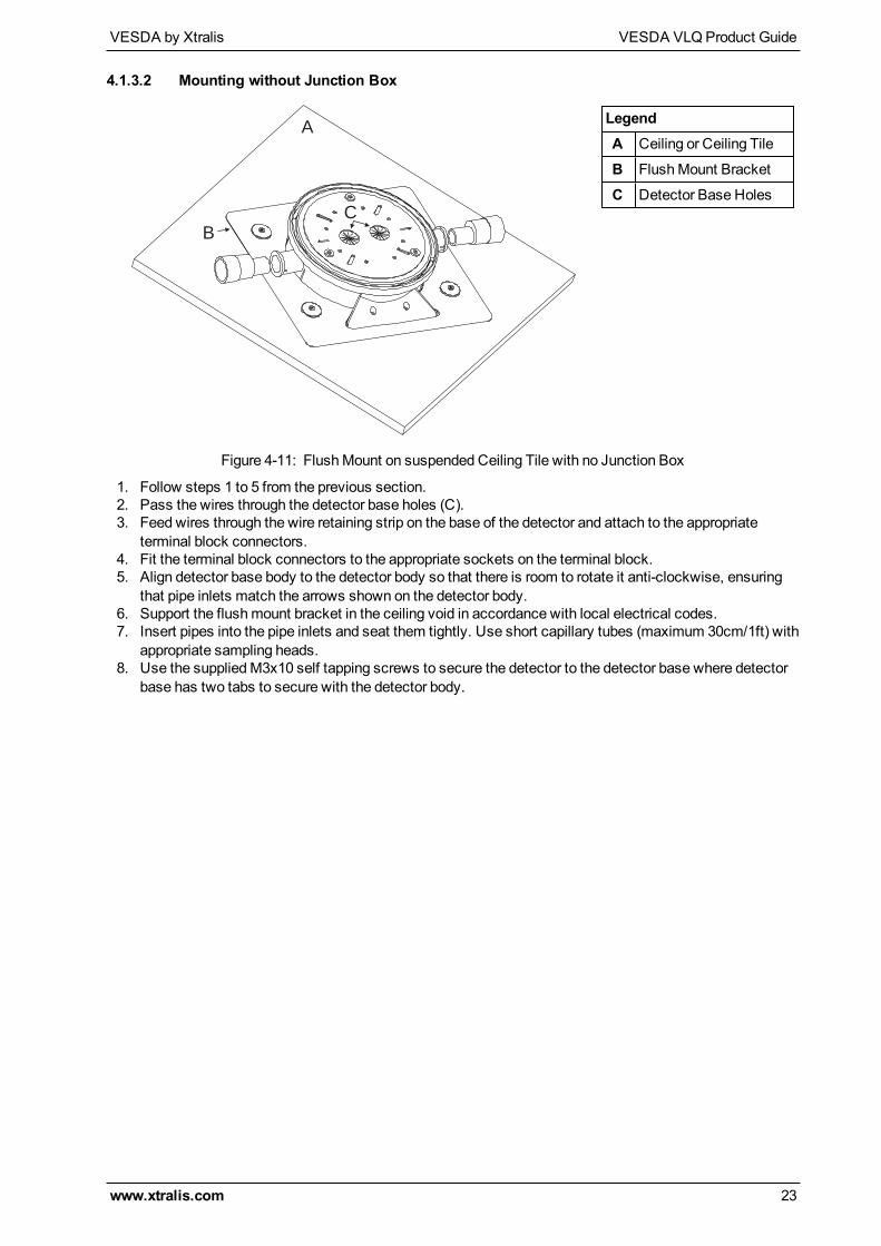
4.1.3.2 Mounting without Junction Box
A
B
C
LegendA Ceiling or Ceiling Tile
B FlushMount Bracket
C Detector Base Holes
Figure 4-11: FlushMount on suspended Ceiling Tile with no Junction Box
1. Follow steps 1 to 5 from the previous section.2. Pass the wires through the detector base holes (C).3. Feed wires through the wire retaining strip on the base of the detector and attach to the appropriate
terminal block connectors.4. Fit the terminal block connectors to the appropriate sockets on the terminal block.5. Align detector base body to the detector body so that there is room to rotate it anti-clockwise, ensuring
that pipe inlets match the arrows shown on the detector body.6. Support the flushmount bracket in the ceiling void in accordance with local electrical codes.7. Insert pipes into the pipe inlets and seat them tightly. Use short capillary tubes (maximum 30cm/1ft) with
appropriate sampling heads.8. Use the suppliedM3x10 self tapping screws to secure the detector to the detector base where detector
base has two tabs to secure with the detector body.
VESDA VLQProduct Guide VESDA by Xtralis
24 www.xtralis.com
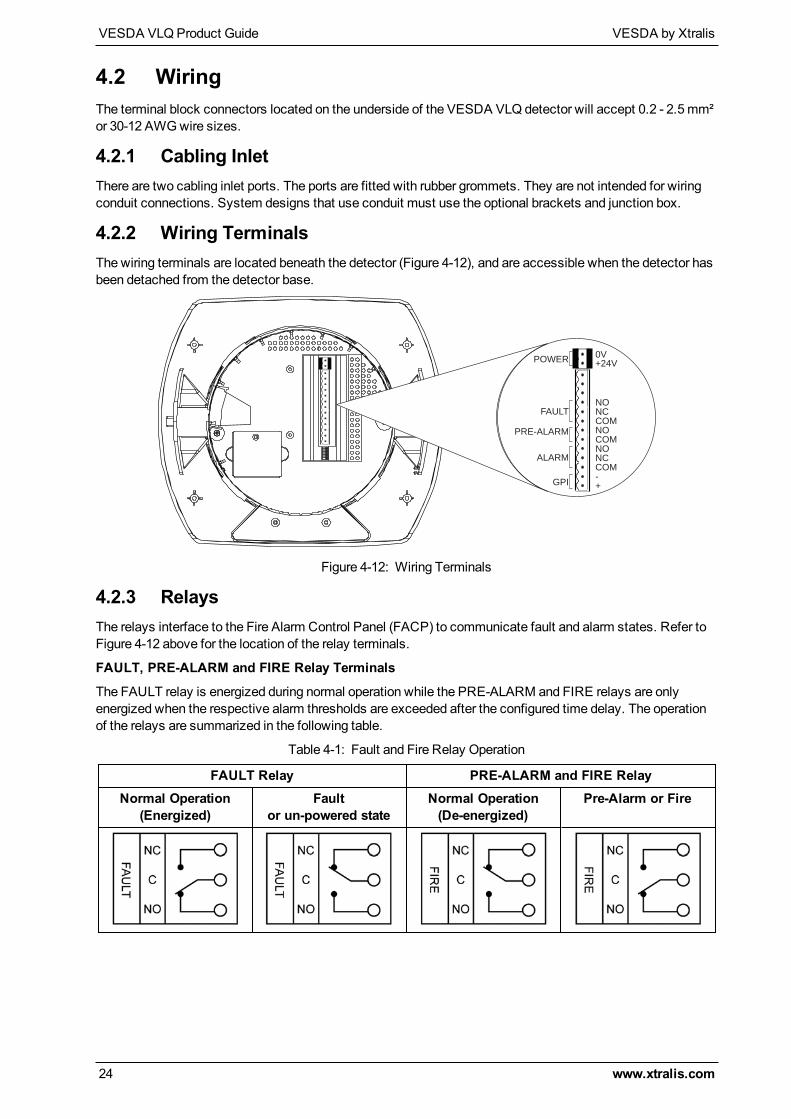
4.2 WiringThe terminal block connectors located on the underside of the VESDA VLQ detector will accept 0.2 - 2.5mm²or 30-12 AWGwire sizes.
4.2.1 Cabling InletThere are two cabling inlet ports. The ports are fitted with rubber grommets. They are not intended for wiringconduit connections. System designs that use conduit must use the optional brackets and junction box.
4.2.2 Wiring TerminalsThe wiring terminals are located beneath the detector (Figure 4-12), and are accessible when the detector hasbeen detached from the detector base.
0V
+24V
NO
NC
COM
NO
COM
NO
NC
COM
-
+
POWER
FAULT
ALARM
PRE-ALARM
GPI
Figure 4-12: Wiring Terminals
4.2.3 RelaysThe relays interface to the Fire Alarm Control Panel (FACP) to communicate fault and alarm states. Refer toFigure 4-12 above for the location of the relay terminals.
FAULT, PRE-ALARM and FIRE Relay Terminals
The FAULT relay is energized during normal operation while the PRE-ALARM and FIRE relays are onlyenergized when the respective alarm thresholds are exceeded after the configured time delay. The operationof the relays are summarized in the following table.
FAULT Relay PRE-ALARM and FIRE RelayNormal Operation
(Energized)Fault
or un-powered stateNormal Operation(De-energized)
Pre-Alarm or Fire
Table 4-1: Fault and Fire Relay Operation
VESDA by Xtralis VESDA VLQProduct Guide
www.xtralis.com 25
4.2.4 Monitored General Purpose Input (GPI)TheGPI is a programmable input which can be configured to initiate a number of different actions, including,by default, a Remote Reset function. Refer to Section 7.3 on page 36 for GPI configuration options.
With monitored GPI, the detector monitors the GPI for open or short circuit faults when theGPI function is setto any value.
When theGPI function parameter is set to PSU monitoring, the detector indicates an external equipment faultcondition by monitoring the line impedance. A 47K End of Line (EOL) resistor is supplied with the product andmust be assembled in parallel with the device to bemonitored.
The EOL resistor provides a known termination to the external equipment, this allows the detector to identifyopen or short circuits.
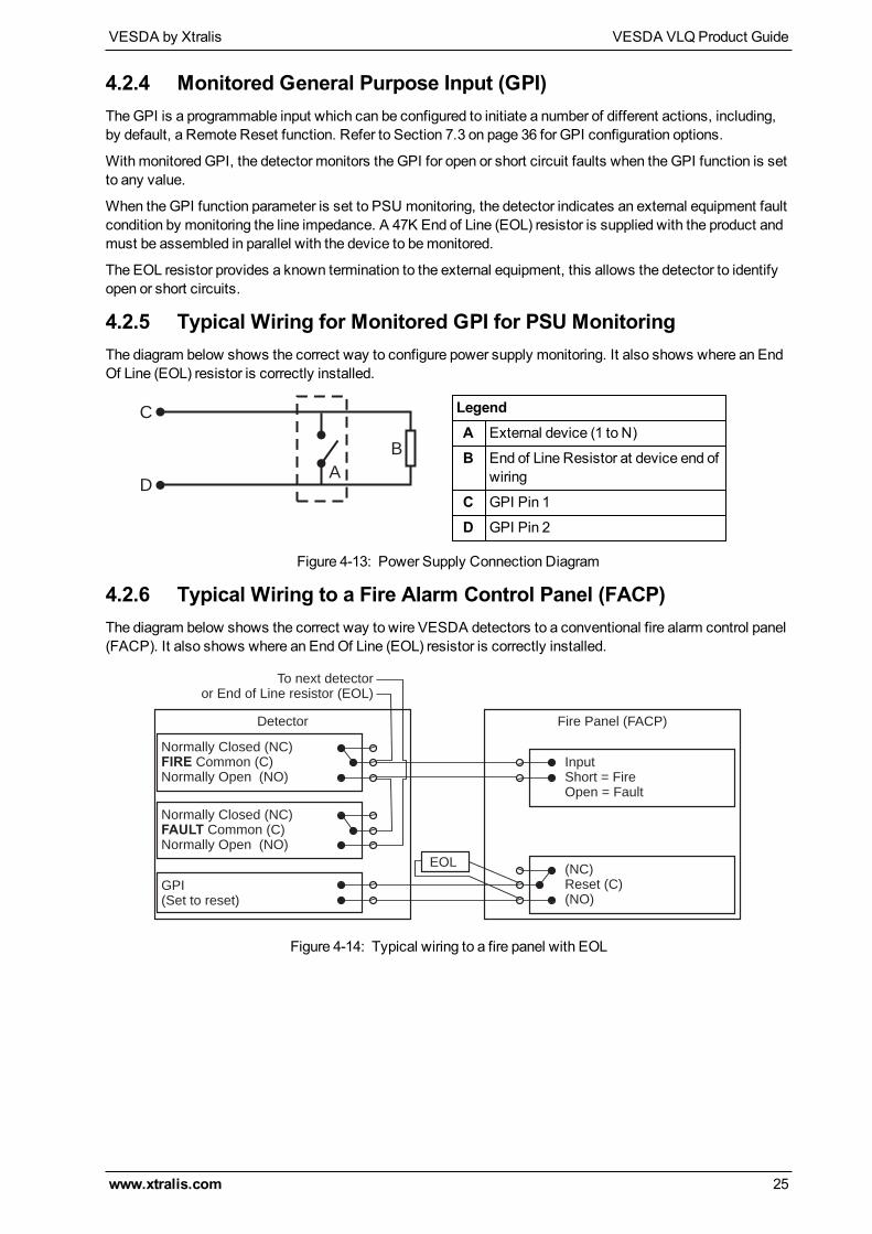
4.2.5 Typical Wiring for Monitored GPI for PSU MonitoringThe diagram below shows the correct way to configure power supply monitoring. It also shows where an EndOf Line (EOL) resistor is correctly installed.
A
B
C
D
LegendA External device (1 to N)
B End of Line Resistor at device end ofwiring
C GPI Pin 1
D GPI Pin 2
Figure 4-13: Power Supply Connection Diagram
4.2.6 Typical Wiring to a Fire Alarm Control Panel (FACP)The diagram below shows the correct way to wire VESDA detectors to a conventional fire alarm control panel(FACP). It also shows where an EndOf Line (EOL) resistor is correctly installed.
Normally Closed (NC)Common (C)
Normally Open (NO)FIRE
Normally Closed (NC)
Normally Open (NO)Common (C)FAULT
GPI(Set to reset)
Detector
(NC)Reset (C)(NO)
InputShort = FireOpen = Fault
To next detectoror End of Line resistor (EOL)
Fire Panel (FACP)
EOL
Figure 4-14: Typical wiring to a fire panel with EOL
VESDA VLQProduct Guide VESDA by Xtralis
26 www.xtralis.com
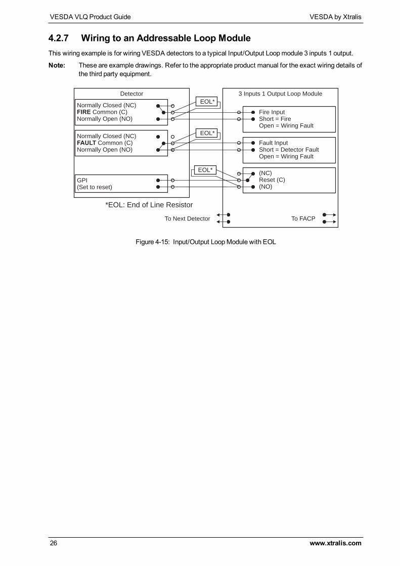
4.2.7 Wiring to an Addressable Loop ModuleThis wiring example is for wiring VESDA detectors to a typical Input/Output Loopmodule 3 inputs 1 output.
Note: These are example drawings. Refer to the appropriate product manual for the exact wiring details ofthe third party equipment.
Normally Closed (NC)Common (C)FIRE
(NO)Normally Open
Normally Closed (NC)Common (C)FAULT
(NO)Normally Open
GPI)(Set to reset
Dete torc
(NC)(C)Reset
(NO)
Fire InputShort = FireOpen = Wiring Fault
3 1Inputs Output Loop Module
To FACPTo Next Detector
Fault InputShort = Detector FaultOpen = Wiring Fault
EOL*
EOL*
*EOL: End of Line Resistor
EOL*
Figure 4-15: Input/Output LoopModule with EOL
VESDA by Xtralis VESDA VLQProduct Guide
www.xtralis.com 27
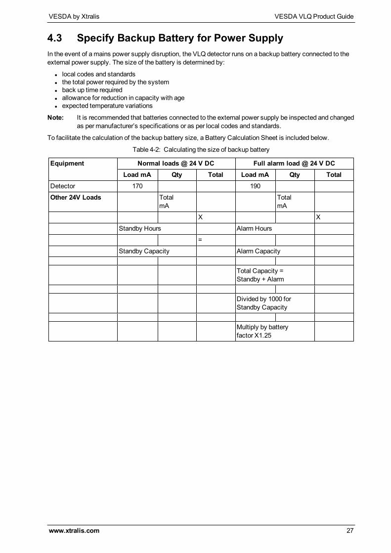
4.3 Specify Backup Battery for Power SupplyIn the event of amains power supply disruption, the VLQ detector runs on a backup battery connected to theexternal power supply. The size of the battery is determined by:
l local codes and standardsl the total power required by the systeml back up time requiredl allowance for reduction in capacity with agel expected temperature variations
Note: It is recommended that batteries connected to the external power supply be inspected and changedas per manufacturer’s specifications or as per local codes and standards.
To facilitate the calculation of the backup battery size, a Battery Calculation Sheet is included below.
Table 4-2: Calculating the size of backup battery
Equipment Normal loads @ 24 V DC Full alarm load @ 24 V DCLoad mA Qty Total Load mA Qty Total
Detector 170 190
Other 24V Loads TotalmA
TotalmA
X X
Standby Hours Alarm Hours
=
Standby Capacity Alarm Capacity
Total Capacity =Standby + Alarm
Divided by 1000 forStandby Capacity
Multiply by batteryfactor X1.25
VESDA VLQProduct Guide VESDA by Xtralis
28 www.xtralis.com
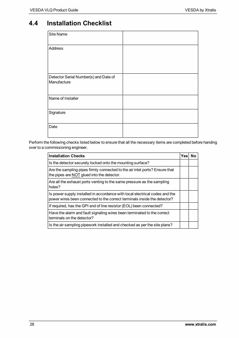
4.4 Installation ChecklistSite Name
Address
Detector Serial Number(s) and Date ofManufacture
Name of Installer
Signature
Date
Perform the following checks listed below to ensure that all the necessary items are completed before handingover to a commissioning engineer.
Installation Checks Yes NoIs the detector securely locked onto themounting surface?
Are the sampling pipes firmly connected to the air inlet ports? Ensure thatthe pipes are NOT glued into the detector.
Are all the exhaust ports venting to the same pressure as the samplingholes?
Is power supply installed in accordance with local electrical codes and thepower wires been connected to the correct terminals inside the detector?
If required, has the GPI end of line resistor (EOL) been connected?
Have the alarm and fault signaling wires been terminated to the correctterminals on the detector?
Is the air sampling pipework installed and checked as per the site plans?
VESDA by Xtralis VESDA VLQProduct Guide
www.xtralis.com 29
4.5 Powering UpAfter installing the detector it is necessary to power up the system. The power up sequence lastsapproximately twominutes.
The VESDA VLQ detector does not have a power switch, i.e it is hard wired to a 24 VDC supply and it isassumed that the power supply has been installed as per manufacturers instructions in accordance with localelectrical codes.
If the system fails to power up, check all power wires are secured to their terminals and that the polarity iscorrect.
On power up:
l The Power LED illuminates and the detector runs a series of self-diagnostic and lamp tests.l If there is a fault, the Fault LED illuminates. To identify the fault, check the fault code on the displaypanel or within the Xtralis QSC software.
l The aspirator starts.It is normal for the detector to display faults immediately after the first power up. Reset the detector using theXtralis QSC software or the reset button on the detector. This will unlatch the relays and turn off the FaultLED. Any remaining faults will cause the Fault LED to illuminate again. Proceed with the preliminary systemcheck.
4.6 Preliminary System CheckA preliminary system check is required after installing the VESDA VLQ detector, before it is commissioned foruse. The check can be conducted by using buttons on the detector or by connecting to the detector using theXtralis QSC software. The preliminary systems check includes:
l Normalizing the air flow. Activate the normalization process using the N button on the detector or byusing Xtralis QSC.
l Conducting a basic smoke test.l Check interface to FACP, i.e. verify alarm and fault conditions.

VESDA VLQProduct Guide VESDA by Xtralis
30 www.xtralis.com
This page is intentionally left blank.
VESDA by Xtralis VESDA VLQProduct Guide
www.xtralis.com 31
5 ConfigurationThe VESDA VLQ detector is configured using the Xtralis QSC software or onboard DIP switches.
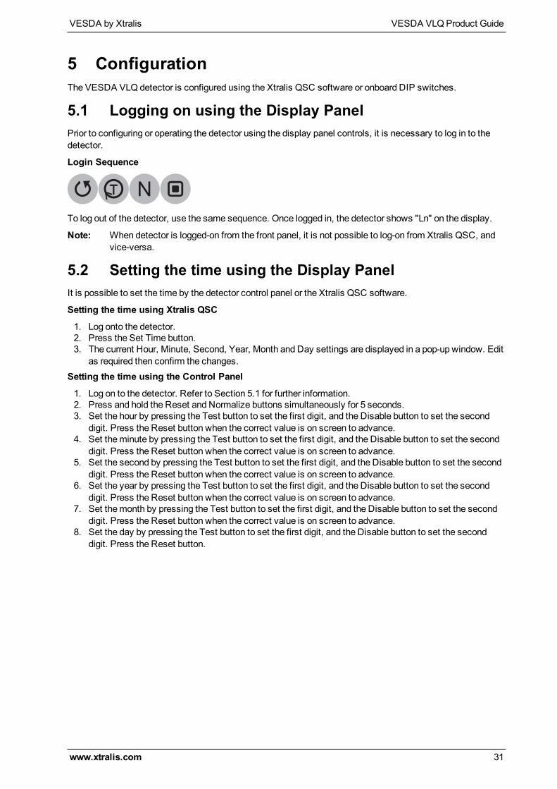
5.1 Logging on using the Display PanelPrior to configuring or operating the detector using the display panel controls, it is necessary to log in to thedetector.
Login Sequence
To log out of the detector, use the same sequence. Once logged in, the detector shows "Ln" on the display.
Note: When detector is logged-on from the front panel, it is not possible to log-on from Xtralis QSC, andvice-versa.
5.2 Setting the time using the Display PanelIt is possible to set the time by the detector control panel or the Xtralis QSC software.
Setting the time using Xtralis QSC
1. Log onto the detector.2. Press the Set Time button.3. The current Hour, Minute, Second, Year, Month and Day settings are displayed in a pop-up window. Edit
as required then confirm the changes.Setting the time using the Control Panel
1. Log on to the detector. Refer to Section 5.1 for further information.2. Press and hold the Reset and Normalize buttons simultaneously for 5 seconds.3. Set the hour by pressing the Test button to set the first digit, and the Disable button to set the second
digit. Press the Reset button when the correct value is on screen to advance.4. Set theminute by pressing the Test button to set the first digit, and the Disable button to set the second
digit. Press the Reset button when the correct value is on screen to advance.5. Set the second by pressing the Test button to set the first digit, and the Disable button to set the second
digit. Press the Reset button when the correct value is on screen to advance.6. Set the year by pressing the Test button to set the first digit, and the Disable button to set the second
digit. Press the Reset button when the correct value is on screen to advance.7. Set themonth by pressing the Test button to set the first digit, and the Disable button to set the second
digit. Press the Reset button when the correct value is on screen to advance.8. Set the day by pressing the Test button to set the first digit, and the Disable button to set the second
digit. Press the Reset button.
VESDA VLQProduct Guide VESDA by Xtralis
32 www.xtralis.com
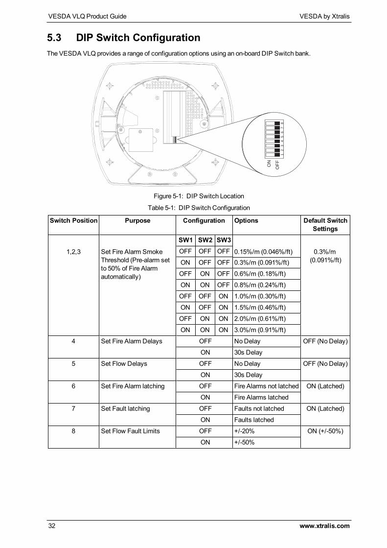
5.3 DIP Switch ConfigurationThe VESDA VLQ provides a range of configuration options using an on-board DIP Switch bank.
12
34
56
78
ON
OF
F
Figure 5-1: DIP Switch Location
Switch Position Purpose Configuration Options Default SwitchSettings
1,2,3 Set Fire Alarm SmokeThreshold (Pre-alarm setto 50% of Fire Alarmautomatically)
SW1 SW2 SW3
0.15%/m (0.046%/ft) 0.3%/m(0.091%/ft)
OFF OFF OFF
ON OFF OFF 0.3%/m (0.091%/ft)
OFF ON OFF 0.6%/m (0.18%/ft)
ON ON OFF 0.8%/m (0.24%/ft)
OFF OFF ON 1.0%/m (0.30%/ft)
ON OFF ON 1.5%/m (0.46%/ft)
OFF ON ON 2.0%/m (0.61%/ft)
ON ON ON 3.0%/m (0.91%/ft)
4 Set Fire Alarm Delays OFF NoDelay OFF (NoDelay)
ON 30s Delay
5 Set Flow Delays OFF NoDelay OFF (No Delay)
ON 30s Delay
6 Set Fire Alarm latching OFF Fire Alarms not latched ON (Latched)
ON Fire Alarms latched
7 Set Fault latching OFF Faults not latched ON (Latched)
ON Faults latched
8 Set Flow Fault Limits OFF +/-20% ON (+/-50%)
ON +/-50%
Table 5-1: DIP Switch Configuration
VESDA by Xtralis VESDA VLQProduct Guide
www.xtralis.com 33
6 CommissioningThe VESDA VLQ has been designed to simplify the commissioning process. The AutoLearn function allowsthe unit to assess its environment and setup appropriate alarm thresholds.
The detector is monitored during commissioning using Xtralis QSC.
Once the VESDA VLQ detector has been commissioned, it will report alarms and faults according to theparameters defined during installation.
Note: Detectors should be commissioned with a smoke test.
Prior to commissioning the detector:
1. Check that the pipe network is clean and correctly fitted with all joints correctly glued (except where thepipe enters the detector, whichmust not be glued).
2. Check that the power is connected and on. Let the detector run for around 5minutes. Ignore the faultsduring this time. Reset the detector after 5minutes of operation.
3. Normalize the airflow. This takes approximately 5minutes.4. Reset the detector after normalization. It should now be running without faults.
It is important that the protected environment is representative of normal operating conditions during theAutoLearn process.
For code-specific information, see Codes and Standards Information for Air Sampling Smoke Detection onpage iii.
6.1 AutoLearn SmokeAutoLearn Smoke is initiated by using controls on the front panel or from within Xtralis QSC.
During the AutoLearn Smoke process, the detector determines the average smoke and peak smokeobscuration levels and sets suitable alarm thresholds for the operating environment. This process willminimize nuisance alarms due to normal environmental background variations.
During the learning cycle, if an alarm condition occurs, AutoLearn will not complete its cycle. In this situationthe user must restart the AutoLearn process. If AutoLearn is halted, the alarm thresholds will be left at theprevious settings.
Conditions experienced during learning are assumed to be representative of normal operating conditions.
The AutoLearn Smoke learning times range from 15minutes to 2 hours.
Note: AutoLearn Smoke thresholds are volatile, therefore if thresholds are set using AutoLearn smokethen it must be run each time the detector is powered up.
6.2 Commissioning Smoke TestIt is recommended that a smoke test be carried out to verify the integrity of the pipe network, to demonstratethat the system is working and tomeasure the transport time to the detector.
This test involves introducing a smoke sample at the furthest sampling hole and thenmeasuring the timetaken for the smoke to travel to the detector. Results are logged and compared to subsequent tests to notevariations of the system.

VESDA VLQProduct Guide VESDA by Xtralis
34 www.xtralis.com
This page is intentionally left blank.
VESDA by Xtralis VESDA VLQProduct Guide
www.xtralis.com 35
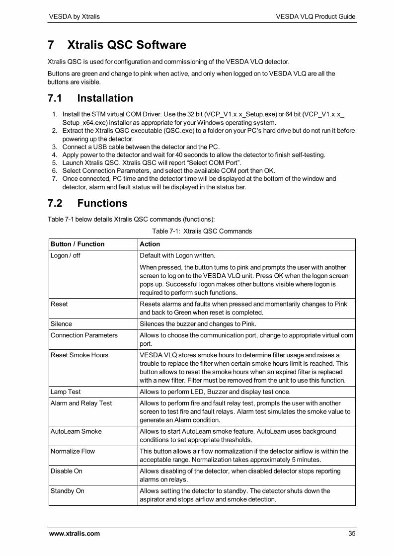
7 Xtralis QSC SoftwareXtralis QSC is used for configuration and commissioning of the VESDA VLQ detector.
Buttons are green and change to pink when active, and only when logged on to VESDA VLQ are all thebuttons are visible.
7.1 Installation1. Install the STM virtual COMDriver. Use the 32 bit (VCP_V1.x.x_Setup.exe) or 64 bit (VCP_V1.x.x_
Setup_x64.exe) installer as appropriate for yourWindows operating system.2. Extract the Xtralis QSC executable (QSC.exe) to a folder on your PC's hard drive but do not run it before
powering up the detector.3. Connect a USB cable between the detector and the PC.4. Apply power to the detector and wait for 40 seconds to allow the detector to finish self-testing.5. Launch Xtralis QSC. Xtralis QSC will report “Select COM Port”.6. Select Connection Parameters, and select the available COM port thenOK.7. Once connected, PC time and the detector time will be displayed at the bottom of the window and
detector, alarm and fault status will be displayed in the status bar.
7.2 FunctionsTable 7-1 below details Xtralis QSC commands (functions):
Button / Function ActionLogon / off Default with Logon written.
When pressed, the button turns to pink and prompts the user with anotherscreen to log on to the VESDA VLQ unit. Press OK when the logon screenpops up. Successful logonmakes other buttons visible where logon isrequired to perform such functions.
Reset Resets alarms and faults when pressed andmomentarily changes to Pinkand back to Green when reset is completed.
Silence Silences the buzzer and changes to Pink.
Connection Parameters Allows to choose the communication port, change to appropriate virtual comport.
Reset Smoke Hours VESDA VLQ stores smoke hours to determine filter usage and raises atrouble to replace the filter when certain smoke hours limit is reached. Thisbutton allows to reset the smoke hours when an expired filter is replacedwith a new filter. Filter must be removed from the unit to use this function.
Lamp Test Allows to perform LED, Buzzer and display test once.
Alarm and Relay Test Allows to perform fire and fault relay test, prompts the user with anotherscreen to test fire and fault relays. Alarm test simulates the smoke value togenerate an Alarm condition.
AutoLearn Smoke Allows to start AutoLearn smoke feature. AutoLearn uses backgroundconditions to set appropriate thresholds.
Normalize Flow This button allows air flow normalization if the detector airflow is within theacceptable range. Normalization takes approximately 5minutes.
Disable On Allows disabling of the detector, when disabled detector stops reportingalarms on relays.
Standby On Allows setting the detector to standby. The detector shuts down theaspirator and stops airflow and smoke detection.
Table 7-1: Xtralis QSC Commands
VESDA VLQProduct Guide VESDA by Xtralis
36 www.xtralis.com
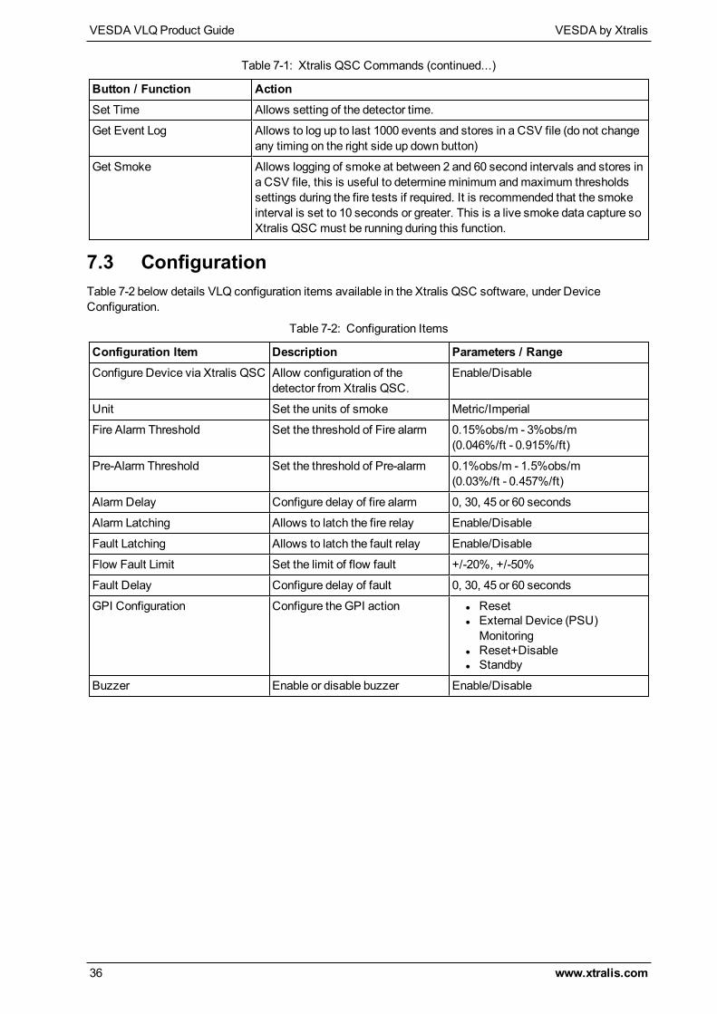
Button / Function ActionSet Time Allows setting of the detector time.
Get Event Log Allows to log up to last 1000 events and stores in a CSV file (do not changeany timing on the right side up down button)
Get Smoke Allows logging of smoke at between 2 and 60 second intervals and stores ina CSV file, this is useful to determineminimum andmaximum thresholdssettings during the fire tests if required. It is recommended that the smokeinterval is set to 10 seconds or greater. This is a live smoke data capture soXtralis QSC must be running during this function.
Table 7-1: Xtralis QSC Commands (continued...)
7.3 ConfigurationTable 7-2 below details VLQ configuration items available in the Xtralis QSC software, under DeviceConfiguration.
Configuration Item Description Parameters / RangeConfigure Device via Xtralis QSC Allow configuration of the
detector from Xtralis QSC.Enable/Disable
Unit Set the units of smoke Metric/Imperial
Fire Alarm Threshold Set the threshold of Fire alarm 0.15%obs/m - 3%obs/m(0.046%/ft - 0.915%/ft)
Pre-Alarm Threshold Set the threshold of Pre-alarm 0.1%obs/m - 1.5%obs/m(0.03%/ft - 0.457%/ft)
Alarm Delay Configure delay of fire alarm 0, 30, 45 or 60 seconds
Alarm Latching Allows to latch the fire relay Enable/Disable
Fault Latching Allows to latch the fault relay Enable/Disable
Flow Fault Limit Set the limit of flow fault +/-20%, +/-50%
Fault Delay Configure delay of fault 0, 30, 45 or 60 seconds
GPI Configuration Configure the GPI action l Resetl External Device (PSU)Monitoring
l Reset+Disablel Standby
Buzzer Enable or disable buzzer Enable/Disable
Table 7-2: Configuration Items
VESDA by Xtralis VESDA VLQProduct Guide
www.xtralis.com 37
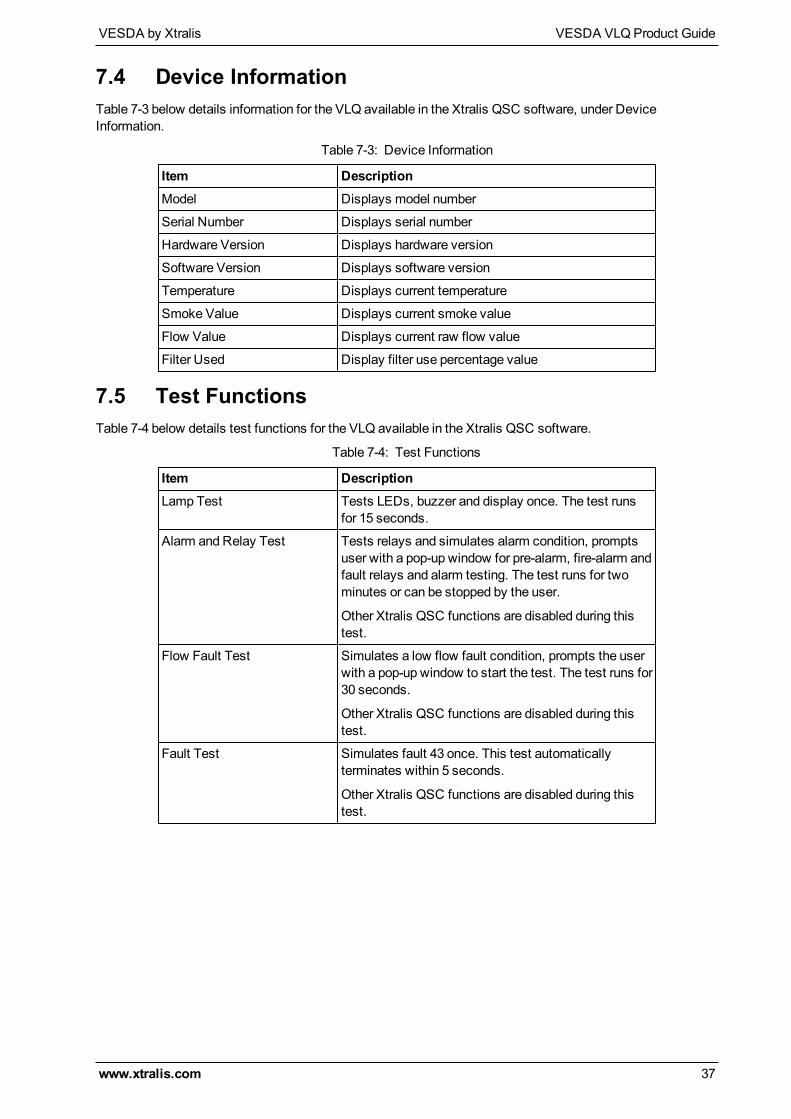
7.4 Device InformationTable 7-3 below details information for the VLQ available in the Xtralis QSC software, under DeviceInformation.
Item DescriptionModel Displays model number
Serial Number Displays serial number
Hardware Version Displays hardware version
Software Version Displays software version
Temperature Displays current temperature
Smoke Value Displays current smoke value
Flow Value Displays current raw flow value
Filter Used Display filter use percentage value
Table 7-3: Device Information
7.5 Test FunctionsTable 7-4 below details test functions for the VLQ available in the Xtralis QSC software.
Item DescriptionLamp Test Tests LEDs, buzzer and display once. The test runs
for 15 seconds.
Alarm and Relay Test Tests relays and simulates alarm condition, promptsuser with a pop-up window for pre-alarm, fire-alarm andfault relays and alarm testing. The test runs for twominutes or can be stopped by the user.
Other Xtralis QSC functions are disabled during thistest.
Flow Fault Test Simulates a low flow fault condition, prompts the userwith a pop-up window to start the test. The test runs for30 seconds.
Other Xtralis QSC functions are disabled during thistest.
Fault Test Simulates fault 43 once. This test automaticallyterminates within 5 seconds.
Other Xtralis QSC functions are disabled during thistest.
Table 7-4: Test Functions

VESDA VLQProduct Guide VESDA by Xtralis
38 www.xtralis.com
This page is intentionally left blank.
VESDA by Xtralis VESDA VLQProduct Guide
www.xtralis.com 39
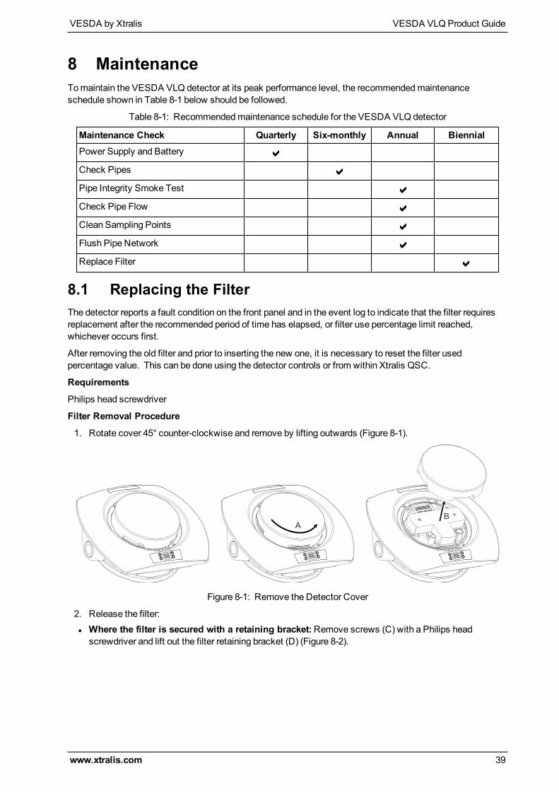
8 MaintenanceTomaintain the VESDA VLQ detector at its peak performance level, the recommendedmaintenanceschedule shown in Table 8-1 below should be followed.
Maintenance Check Quarterly Six-monthly Annual BiennialPower Supply and Battery
Check Pipes
Pipe Integrity Smoke Test
Check Pipe Flow
Clean Sampling Points
Flush Pipe Network
Replace Filter
Table 8-1: Recommendedmaintenance schedule for the VESDA VLQ detector
8.1 Replacing the FilterThe detector reports a fault condition on the front panel and in the event log to indicate that the filter requiresreplacement after the recommended period of time has elapsed, or filter use percentage limit reached,whichever occurs first.
After removing the old filter and prior to inserting the new one, it is necessary to reset the filter usedpercentage value. This can be done using the detector controls or from within Xtralis QSC.
Requirements
Philips head screwdriver
Filter Removal Procedure
1. Rotate cover 45° counter-clockwise and remove by lifting outwards (Figure 8-1).
A
B
Figure 8-1: Remove the Detector Cover
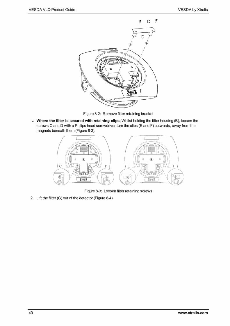
2. Release the filter:l Where the filter is secured with a retaining bracket:Remove screws (C) with a Philips headscrewdriver and lift out the filter retaining bracket (D) (Figure 8-2).
VESDA VLQProduct Guide VESDA by Xtralis
40 www.xtralis.com
D
C
Figure 8-2: Remove filter retaining bracket
l Where the filter is secured with retaining clips:Whilst holding the filter housing (B), loosen thescrews C and D with a Philips head screwdriver.turn the clips (E and F) outwards, away from themagnets beneath them (Figure 8-3).
EDC F
B B
Figure 8-3: Loosen filter retaining screws
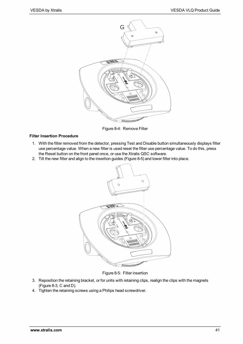
2. Lift the filter (G) out of the detector (Figure 8-4).
VESDA by Xtralis VESDA VLQProduct Guide
www.xtralis.com 41
G
Figure 8-4: Remove Filter
Filter Insertion Procedure
1. With the filter removed from the detector, pressing Test and Disable button simultaneously displays filteruse percentage value. When a new filter is used reset the filter use percentage value. To do this, pressthe Reset button on the front panel once, or use the Xtralis QSC software.
2. Tilt the new filter and align to the insertion guides (Figure 8-5) and lower filter into place.
Figure 8-5: Filter insertion
3. Reposition the retaining bracket, or for units with retaining clips, realign the clips with themagnets(Figure 8-3, C and D).
4. Tighten the retaining screws using a Philips head screwdriver.

VESDA VLQProduct Guide VESDA by Xtralis
42 www.xtralis.com
This page is intentionally left blank.
VESDA by Xtralis VESDA VLQProduct Guide
www.xtralis.com 43
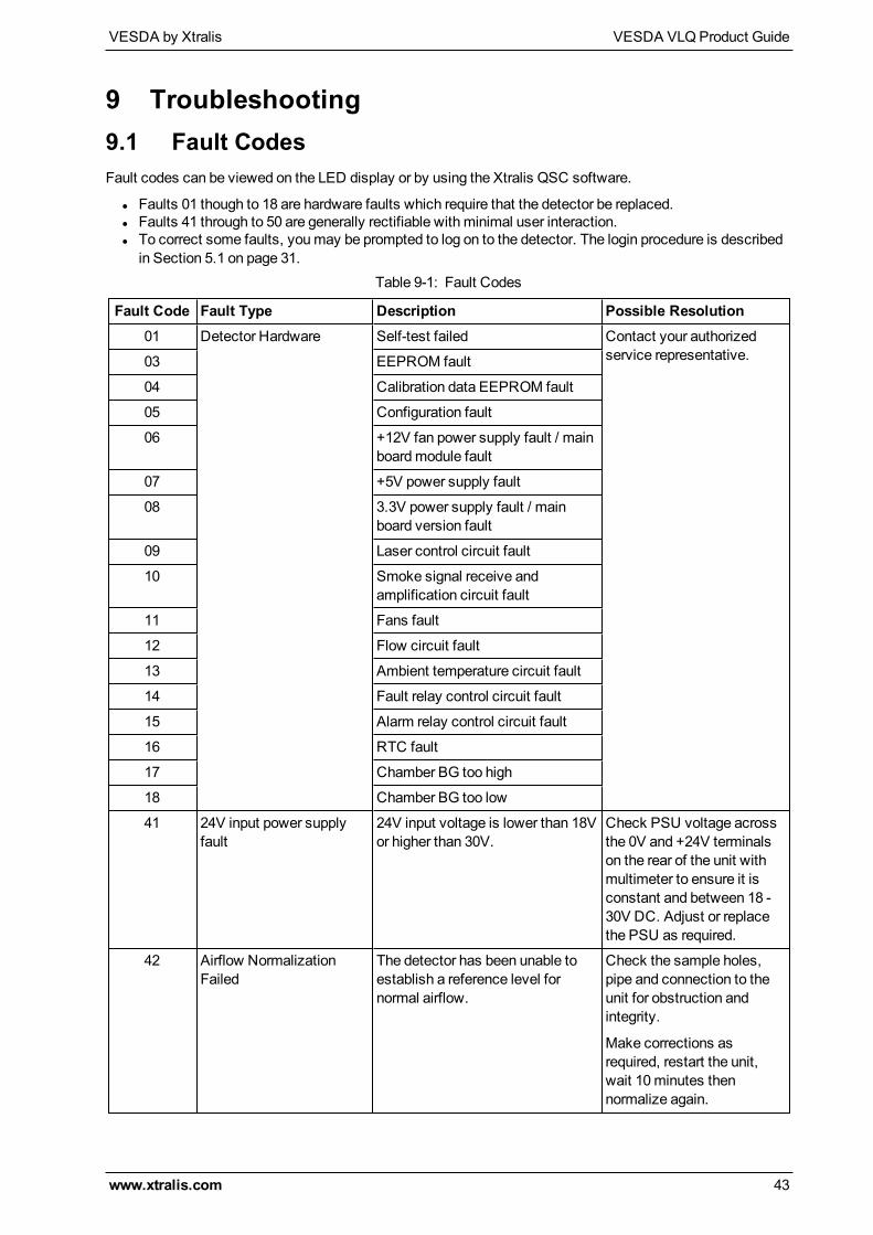
9 Troubleshooting9.1 Fault CodesFault codes can be viewed on the LED display or by using the Xtralis QSC software.
l Faults 01 though to 18 are hardware faults which require that the detector be replaced.l Faults 41 through to 50 are generally rectifiable with minimal user interaction.l To correct some faults, youmay be prompted to log on to the detector. The login procedure is describedin Section 5.1 on page 31.
Fault Code Fault Type Description Possible Resolution01 Detector Hardware Self-test failed Contact your authorized
service representative.03 EEPROM fault
04 Calibration data EEPROM fault
05 Configuration fault
06 +12V fan power supply fault / mainboardmodule fault
07 +5V power supply fault
08 3.3V power supply fault / mainboard version fault
09 Laser control circuit fault
10 Smoke signal receive andamplification circuit fault
11 Fans fault
12 Flow circuit fault
13 Ambient temperature circuit fault
14 Fault relay control circuit fault
15 Alarm relay control circuit fault
16 RTC fault
17 Chamber BG too high
18 Chamber BG too low
41 24V input power supplyfault
24V input voltage is lower than 18Vor higher than 30V.
Check PSU voltage acrossthe 0V and +24V terminalson the rear of the unit withmultimeter to ensure it isconstant and between 18 -30V DC. Adjust or replacethe PSU as required.
42 Airflow NormalizationFailed
The detector has been unable toestablish a reference level fornormal airflow.
Check the sample holes,pipe and connection to theunit for obstruction andintegrity.
Make corrections asrequired, restart the unit,wait 10minutes thennormalize again.
Table 9-1: Fault Codes
VESDA VLQProduct Guide VESDA by Xtralis
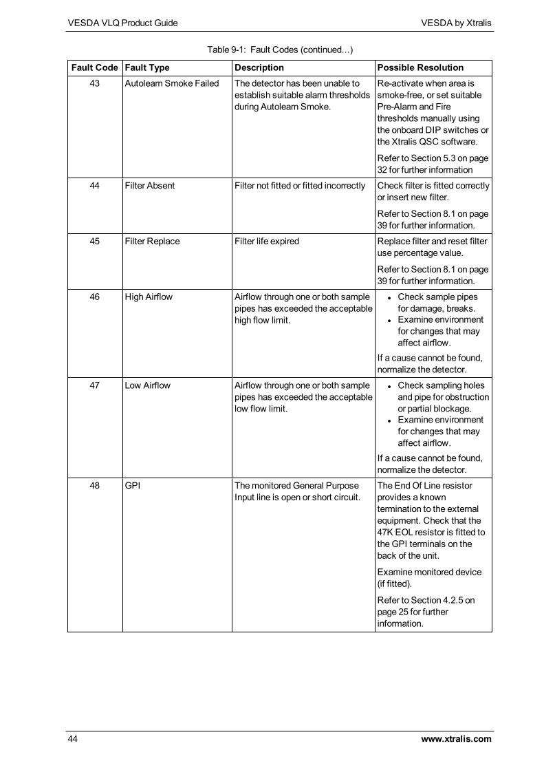
44 www.xtralis.com
Fault Code Fault Type Description Possible Resolution43 Autolearn Smoke Failed The detector has been unable to
establish suitable alarm thresholdsduring Autolearn Smoke.
Re-activate when area issmoke-free, or set suitablePre-Alarm and Firethresholds manually usingthe onboard DIP switches orthe Xtralis QSC software.
Refer to Section 5.3 on page32 for further information
44 Filter Absent Filter not fitted or fitted incorrectly Check filter is fitted correctlyor insert new filter.
Refer to Section 8.1 on page39 for further information.
45 Filter Replace Filter life expired Replace filter and reset filteruse percentage value.
Refer to Section 8.1 on page39 for further information.
46 High Airflow Airflow through one or both samplepipes has exceeded the acceptablehigh flow limit.
l Check sample pipesfor damage, breaks.
l Examine environmentfor changes that mayaffect airflow.
If a cause cannot be found,normalize the detector.
47 Low Airflow Airflow through one or both samplepipes has exceeded the acceptablelow flow limit.
l Check sampling holesand pipe for obstructionor partial blockage.
l Examine environmentfor changes that mayaffect airflow.
If a cause cannot be found,normalize the detector.
48 GPI Themonitored General PurposeInput line is open or short circuit.
The EndOf Line resistorprovides a knowntermination to the externalequipment. Check that the47K EOL resistor is fitted tothe GPI terminals on theback of the unit.
Examinemonitored device(if fitted).
Refer to Section 4.2.5 onpage 25 for furtherinformation.
Table 9-1: Fault Codes (continued...)
VESDA by Xtralis VESDA VLQProduct Guide
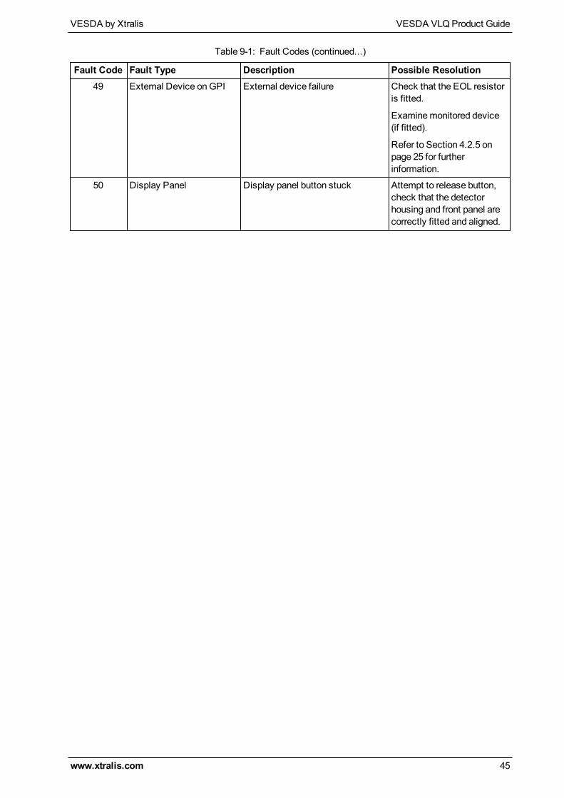
www.xtralis.com 45
Fault Code Fault Type Description Possible Resolution49 External Device onGPI External device failure Check that the EOL resistor
is fitted.
Examinemonitored device(if fitted).
Refer to Section 4.2.5 onpage 25 for furtherinformation.
50 Display Panel Display panel button stuck Attempt to release button,check that the detectorhousing and front panel arecorrectly fitted and aligned.
Table 9-1: Fault Codes (continued...)

VESDA VLQProduct Guide VESDA by Xtralis
46 www.xtralis.com
This page is intentionally left blank.