very large telescope paranal science operations vlti user ... · vlti user manual...
TRANSCRIPT

EUROPEAN SOUTHERN OBSERVATORY
Organisation Europeene pour des Recherches Astronomiques dans l’Hemisphere AustralEuropaische Organisation fur astronomische Forschung in der sudlichen Hemisphare
ESO - European Southern ObservatoryKarl-Schwarzschild Str. 2, D-85748 Garching bei Munchen
Very Large Telescope
Paranal Science Operations
VLTI User Manual
Doc. No. VLT-MAN-ESO-15000-4552
Issue 99.0, Date 12/09/2016
A. MerandPrepared . . . . . . . . . . . . . . . . . . . . . . . . . . . . . . . . . . . . . . . . . .
Date Signature
Approved . . . . . . . . . . . . . . . . . . . . . . . . . . . . . . . . . . . . . . . . . .
Date Signature
S. MieskeReleased . . . . . . . . . . . . . . . . . . . . . . . . . . . . . . . . . . . . . . . . . .
Date Signature

VLTI User Manual VLT-MAN-ESO-15000-4552 ii
This page was intentionally left blank

VLTI User Manual VLT-MAN-ESO-15000-4552 iii
Change Record
Issue Date Section/Parag. affected Remarks
84.0 25/02/2009 All Release for P84 Phase-184.1 22/06/2009 All Release for P84 Phase-285.0 30/08/2009 All Release for P85 Phase-186.0 26/02/2010 MACAO and FINITO part Release for P86 Phase-187.0 28/08/2010 FINITO + AT Baselines Release for P87 Phase-187.1 25/01/2011 FINITO limiting magnitude Release for P87 Phase-288.0 05/03/2011 Release for P88 Phase-190.0 20/02/2012 Release for P90 Phase-191.0 20/08/2012 Release for P91 Phase-192.0 12/03/2013 FINITO limiting magnitude Release for P92 Phase-196.0 17/02/2015 ATs; MIDI removed; PIONIER added Release for P96 Phase-197.0 20/08/2015 Release for P97 Phase-198.0 27/02/2016 GRAVITY; AT- and UT-STS Release for P98 Phase-199.0 12/09/2016 GRAVITY single/dual feed restrictions
on AT baselinesRelease for P99 Phase-1
Editor: Antoine Merand, VLTI System Scientist ; [email protected]

VLTI User Manual VLT-MAN-ESO-15000-4552 iv
Contents
1 INTRODUCTION 1
1.1 Scope . . . . . . . . . . . . . . . . . . . . . . . . . . . . . . . . . . . . . . . . 1
1.2 Contacts . . . . . . . . . . . . . . . . . . . . . . . . . . . . . . . . . . . . . . . 1
2 A FEW WORDS ON INTERFEROMETRY 2
2.1 Introduction . . . . . . . . . . . . . . . . . . . . . . . . . . . . . . . . . . . . . 2
2.2 Interest of interferometry . . . . . . . . . . . . . . . . . . . . . . . . . . . . . . 2
2.3 How an interferometer works . . . . . . . . . . . . . . . . . . . . . . . . . . . . 2
2.4 Interferometric observables . . . . . . . . . . . . . . . . . . . . . . . . . . . . . 3
3 OVERVIEW OF THE VLTI 4
4 THE TELESCOPES FOR THE VLTI 5
4.1 The Unit Telescopes . . . . . . . . . . . . . . . . . . . . . . . . . . . . . . . . 5
4.1.1 Description . . . . . . . . . . . . . . . . . . . . . . . . . . . . . . . . . 5
4.1.2 MACAO . . . . . . . . . . . . . . . . . . . . . . . . . . . . . . . . . . . 5
4.1.3 MACAO isoplanatism . . . . . . . . . . . . . . . . . . . . . . . . . . . 6
4.1.4 Nasmyth guiding without MACAO . . . . . . . . . . . . . . . . . . . . 7
4.1.5 Star Separators (STS) . . . . . . . . . . . . . . . . . . . . . . . . . . . 7
4.2 The Auxiliary Telescopes . . . . . . . . . . . . . . . . . . . . . . . . . . . . . . 7
4.2.1 STRAP . . . . . . . . . . . . . . . . . . . . . . . . . . . . . . . . . . . 7
4.2.2 AT Star Separators (STS) . . . . . . . . . . . . . . . . . . . . . . . . . 9
5 THE BASELINES OF THE VLTI 9
5.1 Introduction . . . . . . . . . . . . . . . . . . . . . . . . . . . . . . . . . . . . . 9
5.2 The delay-lines . . . . . . . . . . . . . . . . . . . . . . . . . . . . . . . . . . . 10
5.3 UT Baselines . . . . . . . . . . . . . . . . . . . . . . . . . . . . . . . . . . . . 11
5.4 AT baselines . . . . . . . . . . . . . . . . . . . . . . . . . . . . . . . . . . . . . 12
6 VLTI STABILIZATION 14
6.1 Introduction . . . . . . . . . . . . . . . . . . . . . . . . . . . . . . . . . . . . . 14
6.2 IRIS . . . . . . . . . . . . . . . . . . . . . . . . . . . . . . . . . . . . . . . . . 14
6.3 Pupil alignment . . . . . . . . . . . . . . . . . . . . . . . . . . . . . . . . . . . 15
6.4 FINITO . . . . . . . . . . . . . . . . . . . . . . . . . . . . . . . . . . . . . . . 15
7 ORGANIZATION OF THE VLTI OBSERVATIONS 17
7.1 General . . . . . . . . . . . . . . . . . . . . . . . . . . . . . . . . . . . . . . . 17
7.2 Calibration . . . . . . . . . . . . . . . . . . . . . . . . . . . . . . . . . . . . . 17
7.3 Preparation of the VLTI observations . . . . . . . . . . . . . . . . . . . . . . . 17
7.4 Baselines and LST constraints . . . . . . . . . . . . . . . . . . . . . . . . . . . 18
7.5 Calibrator selection . . . . . . . . . . . . . . . . . . . . . . . . . . . . . . . . . 18

VLTI User Manual VLT-MAN-ESO-15000-4552 v
7.6 Moon constraints . . . . . . . . . . . . . . . . . . . . . . . . . . . . . . . . . . 18
7.7 Instrument-specific constraints . . . . . . . . . . . . . . . . . . . . . . . . . . . 18
7.8 Target coordinates and magnitude . . . . . . . . . . . . . . . . . . . . . . . . . 18
8 APPENDICES 20
8.1 Feasibility matrices . . . . . . . . . . . . . . . . . . . . . . . . . . . . . . . . . 20
8.1.1 Observations with the UTs . . . . . . . . . . . . . . . . . . . . . . . . . 20
8.1.2 Observations with the ATs . . . . . . . . . . . . . . . . . . . . . . . . . 21
8.2 Sky Coverage . . . . . . . . . . . . . . . . . . . . . . . . . . . . . . . . . . . . 21
List of Figures
1 Basic principle of ground-based long-baseline optical interferometry. The sam-ple of O for the given projected baseline and wavelength is given by the smallcircle (the graphical representation of O is fictive). . . . . . . . . . . . . . . . 3
2 The optical path in the VLTI (when two telescopes are used). . . . . . . . . . 4
3 The optical layout of the lower part of the Coude train and the relay optics . . 6
4 Optical layout of an AT with the telescope optic (M1..M3), Coude train (M4..M8)and relay optic (M9..M11). Note that the lower part of the diagram is not validsince 2015, because the relay optics have been replaced by the Star Separators. 8
5 A unit telescope (left) and an auxiliary telescope (right). . . . . . . . . . . . . 9
6 Layout of VLTI telescope locations. . . . . . . . . . . . . . . . . . . . . . . . . 11
7 AT quadruplet sky coverage and u,v coverage for a target at -15o and 4h ofobservations on each quadruplet. . . . . . . . . . . . . . . . . . . . . . . . . . 13
8 Difference of magnitude between V and H bands, depending on the spectral type. 14
9 UT sky coverage . . . . . . . . . . . . . . . . . . . . . . . . . . . . . . . . . . 22
10 AT sky coverage, small configuration . . . . . . . . . . . . . . . . . . . . . . . 23
11 AT sky coverage, medium configuration . . . . . . . . . . . . . . . . . . . . . . 24
12 AT sky coverage, large configuration . . . . . . . . . . . . . . . . . . . . . . . 25

VLTI User Manual VLT-MAN-ESO-15000-4552 vi
List of Abbreviations
AGB Asymptotic Giant BranchAGN Active Galaxy NucleusAMBER Astronomical Multi-BEam RecombinerAT Auxiliary TelescopeESO European Southern ObservatoryFINITO FrInge-tracker (designed by) NIce and TOrino observatoriesFOV Field Of ViewGRAVITY -IRIS Infra-Red Image SensorLST Local Sidereal TimeMACAO Multi-Application Curvature sensing Adaptive OpticsMIDI MID-infrared Interferometric instrumentOB Observation BlockOPC Observation Program CommitteeOPD Optical Path DifferenceP2PP Phase-2 Proposal PreparationPIONIER Precision Integrated-Optics Near-infrared Imaging ExpeRimentPRIMA Phase-Referencing Imaging and Micro-arcsecond AstrometrySM Service ModeSNR Signal-to-Noise RatioSTRAP System for Tip-tit Removal with Avalanche PhotodiodesSTS Start SeparatorTCCD Technical Charge-Coupled DeviceUSD User Support DepartmentUT Unit TelescopeVCM Variable Curvature MirrorVLT Very Large TelescopeVLTI Very Large Telescope InterferometerVM Visitor ModeYSO Young Stellar Object

VLTI User Manual VLT-MAN-ESO-15000-4552 1
1 INTRODUCTION
1.1 Scope
This document summarizes the characteristics and performances of the Very Large TelescopeInterferometer (VLTI), as it will be offered to astronomers for the six-month ESO observa-tion period P99 (running from 1 April 2017 to 30 September 2017). This document is amandatory complement to the user manuals of the VLTI instruments (AMBER, PIONIERand GRAVITY), since it contains very important information to prepare the proposals forAMBER, PIONIER or GRAVITY. In particular, the requirements by the VLTI sub-systemsfor the feasibility of an observation are listed at the end of this manual.
This version is release for Phase I of P99 and contains some corrections in particular concerningthe guiding on the AT in case of moon and also some informations on the new configurationsoffered for observations with the ATs. Minor corrections were also done over the document.
The bold font is used in the paragraphs of this document to put emphasis on the importantfacts regarding VLTI in P99.
1.2 Contacts
The authors hope that this manual will help the users to get acquainted with the VLTIbefore writing proposals for interferometric observations. This manual is continually evolvingand needs to be improved according to the needs of observers. If you have any question orsuggestion, please contact the ESO User Support Department (email:[email protected]).

VLTI User Manual VLT-MAN-ESO-15000-4552 2
2 A FEW WORDS ON INTERFEROMETRY
2.1 Introduction
This section gives a short summary and a reminder of the principles of interferometry. As-tronomers interested in using the VLTI, but who are not familiar with interferometry yet, canget tutorials from the following links:
• http://olbin.jpl.nasa.gov/intro/index.html (Optical Long Baseline Interferome-try News tutorials).
• http://www.eso.org/sci/facilities/paranal/telescopes/vlti/index.html (VLTIgeneral description and tutorials).
• http://www.mariotti.fr/obsvlti/obsvlti-book.html (proceedings of EuroWinterschool “Observing with the VLTI”).
• http://www.vlti.org (List of other available schools and tutorials.)
2.2 Interest of interferometry
Long-baseline interferometry is a high-angular resolution technique in astronomy. It is usefulto obtain information about details at the milli-arcssecond (mas) level, such as:
• Diameters of stars and intensity profiles across stellar disks.
• Diameters and chemical composition of dusty shells and disks around YSOs and AGBstars.
• Inner structures of AGNi.
• Parameters of the orbits of close binary stars.
2.3 How an interferometer works
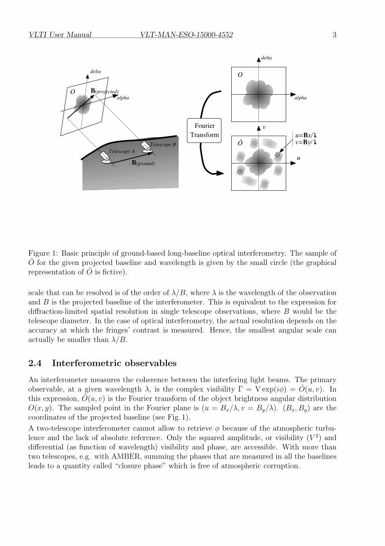
An optical interferometer samples the wave-fronts of the light emitted by a remote target.Sampling is performed at two or more separate locations. The interferometer recombines thesampled wave-fronts to produce interference fringes.
Two telescopes are separated on the ground by a “baseline” vector. The wave-fronts addconstructively or destructively, depending on the path difference between the wave-fronts, andproduce a fringe pattern that appears as bright and dark bands, with the bright bands beingbrighter than the sum of intensities in the two separate wave-fronts. A path-length change inone arm of the interferometer by a fraction of a wavelength causes the fringes to move. If thebeams from the telescopes are combined at a (small) angle, the fringes consist of a spatiallymodulated pattern on the detector.
The angular resolution that the interferometer can achieve depends on the wavelength ofobservation, and on the length of the projected baseline (the projected baseline vector is theprojection of the on-ground baseline vector onto a plane perpendicular to the line-of-sight. Theprojected baseline changes over the night because of Earth rotation). The smallest angular
VLTI User Manual VLT-MAN-ESO-15000-4552 3
B
B(ground)
Telescope ATelescope B
u
v
O
u=Bx/v=By/
delta
delta
alpha alphaO
Ô
FourierTransform
(projected)
Figure 1: Basic principle of ground-based long-baseline optical interferometry. The sample ofO for the given projected baseline and wavelength is given by the small circle (the graphicalrepresentation of O is fictive).
scale that can be resolved is of the order of λ/B, where λ is the wavelength of the observationand B is the projected baseline of the interferometer. This is equivalent to the expression fordiffraction-limited spatial resolution in single telescope observations, where B would be thetelescope diameter. In the case of optical interferometry, the actual resolution depends on theaccuracy at which the fringes’ contrast is measured. Hence, the smallest angular scale canactually be smaller than λ/B.
2.4 Interferometric observables
An interferometer measures the coherence between the interfering light beams. The primaryobservable, at a given wavelength λ, is the complex visibility Γ = V exp(iφ) = O(u, v). Inthis expression, O(u, v) is the Fourier transform of the object brightness angular distributionO(x, y). The sampled point in the Fourier plane is (u = Bx/λ, v = By/λ). (Bx, By) are thecoordinates of the projected baseline (see Fig. 1).
A two-telescope interferometer cannot allow to retrieve φ because of the atmospheric turbu-lence and the lack of absolute reference. Only the squared amplitude, or visibility (V 2) anddifferential (as function of wavelength) visibility and phase, are accessible. With more thantwo telescopes, e.g. with AMBER, summing the phases that are measured in all the baselinesleads to a quantity called “closure phase” which is free of atmospheric corruption.

VLTI User Manual VLT-MAN-ESO-15000-4552 4
Figure 2: The optical path in the VLTI (when two telescopes are used).
3 OVERVIEW OF THE VLTI
The VLTI is located on the top of Cerro Paranal (latitude: 24◦40′ S ; longitude: 70◦25′ W.).There are two main operation modes for the VLTI: the mode using the 8-m unit telescopes(UTs) of the VLT (which are mostly used in stand-alone for non-interferometric observationswith instruments attached to their Cassegrain and Nasmyth foci), and the mode using the1.8-m auxiliary telscopes (ATs) forming the VLT Interferometer Small Array (VISA). Thesetelescopes are not used for stand-alone operation. In both modes, the interferometric instru-ments which can be used are the same. The difference are in terms of sensitivity and (u, v)regions that can be “explored”. The involved VLTI-specific sub-systems are also the same inboth modes:
• An optical system of mirrors to transport the beams.
• A system of delay-lines.
• A set of stabilization devices (IRIS, FINITO, pupil imager...).
These systems are detailed in this manual.
The optical train of the VLTI is illustrated in Fig. 2: the beam from each telescope is trans-ferred by optical reflections through a first tunnel called “light-duct” and then through thedelay-line tunnel (perpendicular to the light-ducts, see Fig. 6), up to the VLTI laboratory.

VLTI User Manual VLT-MAN-ESO-15000-4552 5
4 THE TELESCOPES FOR THE VLTI
The available telescopes for the VLTI observations in P99 are the fixed 8-m UnitTelescopes —UTs— of the VLT (for AMBER and PIONIER only) and the mov-able 1.8-m Auxiliary Telescopes —ATs— (for all VLTI instruments).
4.1 The Unit Telescopes
4.1.1 Description
The VLTI can be attached to the Coude foci of each UT (located underneath the azimuthplatform of the telescope)to bring the stellar light from the Nasmyth focus to the entrance ofa VLTI “light-duct”. The optical layout of the UT Coude train is presented in Fig. 3. As forVLT observations, the telescope is tracking in “field-stabilization” mode: the Nasmyth guideprobe camera tracks on a selected guide star (observable within the ≈ 30 arcmin FOV of theNasmyth focus which is centered on the target observed by the VLTI) by applying tip-tiltcorrection to the M2 mirror of the telescope.
4.1.2 MACAO
Each UT Coude is equipped with an adaptive optics system called MACAO. It consists of aRoddier wavefront curvature sensor which has an array of 60 avalanche photo-diodes. Thisanalyzer applies a correction to the shape the deformable mirror (DM) of the UT Coude. TheDM is mounted on a tip-tilt correction stage onto which the tip-tilt measured by MACAO isoffloaded when the DM is at the limit. When the tip-tilt mount is at the limit, it is offloadedby offsetting the Nasmyth guide probe position, and therefore by offsetting the M2.
The sensitivity of MACAO is V = 16 for a 20% Strehl at λ = 2.2µm. In good conditions,MACAO can be used with a star as faint as V = 17.
If the target is fainter than V = 17 it is possible to perform “off-target Coude guiding” if aguide star can be found within 57.5 of the target. The guide star must be brighter than V =17 but if it is fainter than V >15there is still a risk that Coude guiding could fail dependingon the off-axis distance and sky conditions (seeing, τ0).
We guarantee that the MACAO loop is closed, under the following conditions:
• Seeing less than 1.5 arcsec.
• Coherence time in visible τ0 larger than 2.0ms.
• Airmass less than 2.0.
• Distance from the optical axis less than 57.5 arcsec.
MACAO can be used only if the sky conditions are better than THICK. Rapid changes offlux due to thick clouds passing would degrade the performances of the MACAO and evenendanger the APDs.
In the case where FINITO is used the limitation for the off axis guiding are more stringentand observation can only be performed if the guide star is closer than 13 arcsec.

VLTI User Manual VLT-MAN-ESO-15000-4552 6
Figure 3: The optical layout of the lower part of the Coude train and the relay optics
4.1.3 MACAO isoplanatism
When a guide-star is used, the quality of the correction of the image of the target depends onthe angular distance θ between both objects. The isoplanatic angle is defined as the angulardistance over which the variance of the phase is 1 radian squared. It depends on the Friedparameter r0, the mean altitude of the turbulence layer < h > and the zenith angle z asfollows:
θ0 = 0.31 × r0
< h >,
The mean wavefront error is given by:
< φ2 >= (θ/θ0)2
Because of a limited number of observations in the past with AMBER and off-axis guiding, itis difficult to give figures, but we definitively recommend to observe with a seeing better than0.8 arcsec. When the seeing is 0.8 arcsec, the isoplanatic is in general such that an

VLTI User Manual VLT-MAN-ESO-15000-4552 7
attenuation of 1 K-magnitude per 15 arcsec of separation between the target andthe guide-star is expected. This attenuation has to be taken into account to assessthe feasibility of the target on AMBER, using the K-magnitude of the target. Asimilar magnitude loss can be used in H-band for FINITO, as an approximation.
4.1.4 Nasmyth guiding without MACAO
If no suitable guide star exists, and the requirements on the image quality in the laboratoryare loose, it is still possible to use VLTI with Nasmyth guiding: by offsetting the Nasmythguide probe, the beams can be aligned in the VLTI laboratory. An offset on the guide probewill result into an offset of the M2 mirror (which can be offloaded to the alt-az axes). In thiscase, only the field stabilization by the Nasmyth probe is enabled, and the image quality isusually much lower than what is seen when MACAO is used. Operations without MACAOwere only offered for MIDI observation in Visitor Mode and on a best effort basis. Since MIDIhas been decommissioned in P95, this mode is no longer offered.
4.1.5 Star Separators (STS)
Starting early 2016, all 3 UTs will be equipped with Star-Separators in the Coud rooms belowthe UTs. The goal of the UT-STS is to create two fields:
• One for the VLTI instrument (GRAVITY, AMBER or PIONIER);
• One for the upcoming Infrared Wavefront Sensor, CIAO, for MACAO.
The second field is a requirement for the GRAVITY observations of the galactic center. Theuses of the UT-STS is completely transparent to AMBER and PIONIER users.
4.2 The Auxiliary Telescopes
The VLTI features four auxiliary telescopes (ATs), but only two or three are used at the sametime for scientific observations. Their locations on the VLTI platform (hence the baselinesthey define) are defined in the Paranal schedule which is released before the observation periodstarts. They are usually used several days in a row on the same locations. Relocation of theAT to a new station can only be done during the day. A maximum of 2 ATs can be movedin a single day. Any relocation of ATs is followed by a relocation night that will be used byScience Operations to verify the system before starting normal operations (VM or SM).
Like the UTs, the light from the ATs use a Coude train to bring the stellar light to thedelay-line. A drawing of the Optical layout of the AT is presented in Fig. 4
4.2.1 STRAP
Each AT is equipped with the tip-tilt corrector called STRAP. It consists of four avalanchephoto-diode quadrants which measures the tip-tilt of the incoming wavefront. The measuredtip-tilt is compensated by acting on the M6 mobile mirror of the telescope. When reachingthe limit, the M6 position is offloaded to the alt-az axes of the telescope.
The sensitivity of STRAP on the ATs is V =13.5. If the target is fainter than V =13.5, itis possible to perform “off-target Coude guiding”, provided a suitable guide-star exists. This

VLTI User Manual VLT-MAN-ESO-15000-4552 8
Figure 4: Optical layout of an AT with the telescope optic (M1..M3), Coude train (M4..M8)and relay optic (M9..M11). Note that the lower part of the diagram is not valid since 2015,because the relay optics have been replaced by the Star Separators.
guide-star must be brighter than V =13.5 and closer than 57.5arcsec to the science target.If V >12, there is a risk that Coude guiding cannot be performed, depending on the off-axisdistance and on the sky conditions (seeing, τ0). In the case where FINITO is used the off-axisguide star has to be closer than 15 arcsec for the observation to be possible.
There are some restrictions on the ATs guiding with Strap due to the moon:
• If the FLI is ≥85%, and the guide star is fainter than 9th magnitude, guiding is notpossible for distances to the moon closer than 20 degres.
• If the FLI is ≥85%, and the guide star is brighter than 9th magnitude, guiding is notpossible for distances to the moon closer than 10 degres.
Note that, unlike the UTs, the ATs have no possibility of guiding if they cannot guidewith the Coude. Therefore, it is mandatory to use a suitable Coude guide star (either thetarget itself or an off-axis guide star).
VLTI User Manual VLT-MAN-ESO-15000-4552 9
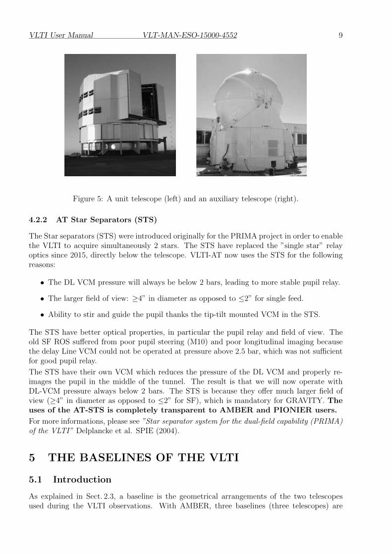
Figure 5: A unit telescope (left) and an auxiliary telescope (right).
4.2.2 AT Star Separators (STS)
The Star separators (STS) were introduced originally for the PRIMA project in order to enablethe VLTI to acquire simultaneously 2 stars. The STS have replaced the ”single star” relayoptics since 2015, directly below the telescope. VLTI-AT now uses the STS for the followingreasons:
• The DL VCM pressure will always be below 2 bars, leading to more stable pupil relay.
• The larger field of view: ≥4” in diameter as opposed to ≤2” for single feed.
• Ability to stir and guide the pupil thanks the tip-tilt mounted VCM in the STS.
The STS have better optical properties, in particular the pupil relay and field of view. Theold SF ROS suffered from poor pupil steering (M10) and poor longitudinal imaging becausethe delay Line VCM could not be operated at pressure above 2.5 bar, which was not sufficientfor good pupil relay.
The STS have their own VCM which reduces the pressure of the DL VCM and properly re-images the pupil in the middle of the tunnel. The result is that we will now operate withDL-VCM pressure always below 2 bars. The STS is because they offer much larger field ofview (≥4” in diameter as opposed to ≤2” for SF), which is mandatory for GRAVITY. Theuses of the AT-STS is completely transparent to AMBER and PIONIER users.
For more informations, please see ”Star separator system for the dual-field capability (PRIMA)of the VLTI” Delplancke et al. SPIE (2004).
5 THE BASELINES OF THE VLTI
5.1 Introduction
As explained in Sect. 2.3, a baseline is the geometrical arrangements of the two telescopesused during the VLTI observations. With AMBER, three baselines (three telescopes) are

VLTI User Manual VLT-MAN-ESO-15000-4552 10
used simultaneously, four telescopes are used simultaneously with PIONIER or GRAVITY.To “explore” the regions of interest in the (u, v) plane of a scientific target, the user has to:
1. Select one or several multiplets (i.e., the set of telescopes): 3T for AMBER and 4T forPIONIER.
2. Define the local sidereal time (LST) ranges for the observation. The LST defines, fromthe selected baseline, the actual “projected” baseline that will define the (u, v) region.
To help with this preparation ESO has made available a tool called VisCal 1 to compute thevisibility of targets as a function of the baseline. Alternatively, one can use the ASPRO tool2,developed by the JMMC. This tool is community based and developed in closed collaborationwith ESO.
All the baselines, at a given time, should use the same type of telescope: it is not possible tocombine an AT and a UT in the same array configuration. The various offered baselines forthe current period can be found online at:
http://www.eso.org/sci/facilities/paranal/telescopes/vlti/configuration/
Section 5.3 and 5.4 provide also this information.
5.2 The delay-lines
The delay-lines are used to compensate the OPD between the two telescopes, from the incom-ing stellar waveplane to the instrument entrance. Each telescope has a dedicated delay-line.
Each delay-line consists of a carriage that can move along rails to adjust the optical pathlength. The carriage contains retro-reflecting optics. One carriage is fixed, whereas the other(2 for AMBER, 3 with PIONIER or GRAVITY) continuously moves in order to compensatethe OPD for the apparent sidereal motion, slow drifts, and (when FINITO is used) atmosphericpiston.
The carriage optics is based on a cat’s eye optical design. The central mirror of the system islocated in an image plane and mounted on a piezo actuator for fine OPD adjustments. Thismirror is the “variable curvature mirror” (VCM): its radius of curvature can be adjusted inreal-time by a pneumatic device that applies a pressure on the back of the mirror. The aim ofthe VCM is to perform a pupil re-imaging (usually very close to the instrument in service) toa desired location, whatever the delay-line position. The advantages of transferring the pupilare:
• An optimized field of view (1.6 to 5 arcsec with the ATs). Fringes can be obtained fromany target within the FOV.
• A reduction of the thermal background related to VLTI optics.
Although the use of the VCMs is not critical for the UT operations, the VCM are used as arule when observing with them.
To compensate OPD drifts due to uncertainty of the array geometry, as well as atmosphericpiston, position offsets can be applied at high rate to the moving delay-line by the OPD
1http://www.eso.org/observing/etc/2http://www.jmmc.fr/aspro

VLTI User Manual VLT-MAN-ESO-15000-4552 11
Figure 6: Layout of VLTI telescope locations.
controller. The OPD controller receives commands either from the science instrument itself(AMBER or PIONIER), or from a fringe-tracker (FINITO).
The optical delay provided by the delay-lines can be between 11 m and 111 m. Dependingon the baseline, there are limitations of the sky accessibility (i.e., alt-az position of the targetto be observed) due to the limitation of the delay-line range. When three baselines are used,the sky accessibility is not simply the superposition of the accessibility of the three baselinesseparately, but a more restricted (alt-az) range due to the inter-dependencies of the delays ofthe three baselines.
5.3 UT Baselines
For P99, All the four unit telescopes are available for VLTI observations. Thefollowing table gives the characteristics of the possible ground baselines (E is the componentover the East direction and N over the North direction):

VLTI User Manual VLT-MAN-ESO-15000-4552 12
Name E (m) N (m) On-ground baseline length (m)
UT1-UT2 24.8 50.8 56.5UT1-UT3 54.8 86.5 102.4UT1-UT4 113.2 64.3 130.2UT2-UT3 30 35.7 46.6UT2-UT4 88.3 13.5 89.3UT3-UT4 58.3 -22.2 62.4
Note that we cannot guarantee that these six baselines will actually be offered in P99. Thefinal subset of realized baselines will depend on the number of requests for each baseline.Therefore, users might be asked later to switch to the next-best baseline. They can alreadyindicate an alternative baseline in their proposals (as a comment to the interferometric table).
For the longest baseline (UT1-UT4 and UT1-UT3), there are limitation for the direction ofpointing in the sky, related to the range of the delay-lines. The VisCalc tool (see Sect. 7.4)gives the possible limits. A quick look at the accessibility range (target declination and hourangle of the observation) can be found at the end of this document (section 8.2), as well as onthe following page:
http://www.eso.org/sci/facilities/paranal/telescopes/vlti/configuration/
5.4 AT baselines
Auxiliary Telescopes are offered as 4 telescopes configurations. In these 4-telescopes setup,every possible 3 telescopes configurations can be used for operations during the same nightby AMBER. The change from one of the available triplet to a different one only requires aconfiguration at the level of the VLTI Laboratory. Such a change of configuration takesabout 10 minutes. Changing quadruplets require to physically move ATs. Only 2 ATs canbe moved per day, so 2 days are required to change quadruplet.
The list of available quadruplets of telescopes offered for P99 is listed below, their u,v and skycoverages of the 3 main quadruplets are shown on Fig. 7:
• Large (60 to 140m): A0 - G1 - J2 - J3 (not available for GRAVITY dual feed)
• Large ”all-south”: A0 - G1 - J2 - K0 (only for GRAVITY dual feed)
• Medium (40 to 100m): D0 - G2 - J3 - K0 (not available for GRAVITY dual feed)
• Small (10 to 40m): A0 - B2 - C1 - D0 (for GRAVITY single and dual feed)
At the time of Phase I, user are only requested to provide informations on which of the availablequadruplets they wish to use for observations. The decision on which specific baselines will beused at the time of the observation will be made at the time of the Phase II or in preparationof the visitor run.
AMBER observations can be carried out with any of the following triplets of baselines:
-
For a requested quadruplet or triplet, the pointing restrictions (depending on the target decli-nation and on the hour angle of the observation), due to delay-line range and/or vignetting by

VLTI User Manual VLT-MAN-ESO-15000-4552 13
Figure 7: AT quadruplet sky coverage and u,v coverage for a target at -15o and 4h of obser-vations on each quadruplet.
the neighboring telescope enclosures, can be found at the end of this document (section 8.2),as well as on the following page:
http://www.eso.org/sci/facilities/paranal/telescopes/vlti/configuration/

VLTI User Manual VLT-MAN-ESO-15000-4552 14
Figure 8: Difference of magnitude between V and H bands, depending on the spectral type.
6 VLTI STABILIZATION
6.1 Introduction
In this section, we describe the sub-systems of the VLTI that are used for “non-blind tracking”:each of these sub-systems consists of a sensor retro-feeding one or several mechanical actuators.The aim of these systems is to provide stable beams to the instrument by correcting the effectsof the atmospheric turbulence, or of the mechanical defects (vibrations, roll/pitch/yaw, etc...).As many of these sub-systems use the stellar light as input signals, it is important to knowtheir performances to assess the feasibility of the observation proposals.
6.2 IRIS
IRIS is the infrared field-stabilizer of the VLTI. It consists of a fast infrared (K-band) cam-era onto which the images from each beam are projected (1 image per detector quadrant).The photocenters of each beam are measured in real-time. Its purpose is to perform field-stabilization on the telescopes by measuring the low-frequency tip-tilt from the VLTI labora-tory. IRIS guarantees, therefore, the correct alignment of the beam during the observations.
There are two modes for IRIS: slow-guiding, and fast-guiding. In slow-guiding, the tip-tiltcorrections are sent to XY-tables of the telescope to correct the pointing of the telescopes.The frequency of the correction is around 1 s. The fast-guiding is used for FINITO (seeSect. 6.4) and for AMBER. In this mode, the tip-tilt corrections are sent to the FINITOACUs, and corrections are sent every 10 ms.
Although the users are requested to give the H-magnitude in the instrument OBs, this valuecan be used as an approximation of the K-magnitude for IRIS, and allows IRIS to work atits best performances, thanks to an adaptive integration time algorithm. An approximationof the H-magnitude can be found from the V-magnitude and the spectral type of the target,using the plot on Fig. 8.
The limiting magnitudes in K-band for IRIS are:

VLTI User Manual VLT-MAN-ESO-15000-4552 15
• In slow-guiding:
– K = 8.0 with the ATs.
– K = 11.5 with the UTs.
• In fast-guiding (required for FINITO):
– K = 5.0 with the ATs.
– K = 8.5 with the UTs.
6.3 Pupil alignment
Due to a random slight warp of the delay-line rails, the transverse location of the pupil foreach beam in the VLTI laboratory may vary with the position of the delay-line carriage of thebeam. A re-alignment of the tip-tilt of the M10 mirrors (located in an image plane) of thetelescopes is needed to re-center the pupil of the beams. The pupil position is measured byIRIS in the VLTI laboratory and corrected.
The limiting magnitudes in the visible which allow the pupil alignment are:
• K = 5.0, with the ATs.
• K = 8.5, with the UTs.
For most of the calibrator stars, the pupil can be aligned. For scientific targets that are toofaint in the visible to allow the pupil alignment, one has to rely on the quality of the delay-linerails: the experience shows that, if the pupil has been previously aligned for the calibrator,the delay-line carriages are usually not moved far away when observing the scientific target,so the pupil shift (measured when the target pupil can be seen) is often negligible. For thisreason (but not only), the angular distance between both objects has to be taken into accountwhen one is selecting a calibrator. Anyway, the pupil alignment will usually be performed onthe scientific target whenever it is bright enough.
6.4 FINITO
FINITO is the VLTI fringe-tracker. Its purpose is to compensate at high rate the atmosphericpiston between the telescopes that are used by an interferometric instrument, in order tostabilize the fringes produced by this instrument. FINITO produces and measures fringes inH-band. It is fed by either two beams or three beams. In this later case, fringes are made ontwo pairs (i.e., two baselines) only. Therefore, in three-beam mode, one of the three beams iscommon to the two interferometric channels of FINITO.
For each channel/baseline, FINITO measures the position of the fringe packet and its phase,and sends this information to the OPD controller which moves the delay-line. When FINITOis used with three beams (for AMBER observations), the reference delay-line (the one set toa fixed position) corresponds to the beam-0 of FINITO which is common to the two interfero-metric channels. This, coupled with the fact that the order of the baselines (which telescopesgoes into which input channel of Finito) will introduces extra limits in the sky accessibility(already limited by the delay-line range and the shadowing of the telescopes.). As such theobservability of targets with or without FINITO maybe different.

VLTI User Manual VLT-MAN-ESO-15000-4552 16
In standard operation, FINITO performs cophasing whenever the fringe SNR is enough. If thefringe SNR decreases, FINITO switch to coherencing and switches back to cophasing whenthe SNR improves.
The performances of FINITO are:
• Typical residual phase (ATs): 200 nm RMS.
• Limiting magnitude ATs: -2 < H < 5.5
• Limiting magnitude UTs: 1 < H < 8.
• Limiting visibility in H: 15 % (ATs), 10% (UTs)
IRIS has to be used on fast-guiding mode. More detailed information are available on theperformance of AMBER+FINITO are available on the AMBER Web page at:
http://www.eso.org/sci/facilities/paranal/instruments/amber/inst/

VLTI User Manual VLT-MAN-ESO-15000-4552 17
7 ORGANIZATION OF THE VLTI OBSERVATIONS
7.1 General
For P99, VLTI observations can be performed either in service mode or in visitormode. For the phase-1 of a period, the unique contact point at ESO for the user is the UserSupport Department (see Sect. 1.5). For the phase-2, USD is still the contact point for servicemode, and the Paranal Science Operation department is the contact point for visitor mode:see http://www.eso.org/observing/p2pp/VisitorMode.html.
The visitor mode is more likely to be offered for proposals requiring non-standardobservation procedures. The OPC will decide whether a proposal should be observed inSM or VM. As for any other instrument, ESO reserves the right to transfer visitor programsto service and vice-versa.
7.2 Calibration
The raw visibility µ measured on a target by an interferometer is always lower than thetheoretical expected visibility V. The transfer function of an interferometer is given by T =µ/V . In order to determine T , the method is to observe a star with a stable and known angulardiameter called a “calibrator” for which the expected visibility V0 is known. Measuring its rawvisibility µ0 gives an estimate of T that can be used to calibrate the visibility on a scientifictarget.
For each scientific target observed, a calibrator has to be observed right after or before. It is upto the user to select the calibrator of the scientific target. The criterion to select a calibratormay include.
• Stable angular diameter known with a good precision, or unresolved (V0 ≈ 1.0) objectfor baseline and wavelength of the observation.
• Proximity in the sky to the scientific target.
• Magnitude comparable to the scientific target
Calibrators can be selected using the CalVin tool (see Sect. 7.5). Alternatively, the JMMCtool named SearchCal can be used.
7.3 Preparation of the VLTI observations
To assess the feasibility of an observation (mostly in term of limiting magnitudes in differentspectral bands), the following tools need to be used:
• This manual.
• The instrument manual (PIONIER or AMBER).
• The “VisCalc” tool.
• The “CalVin” tool.
Other software packages exists. In particular, one can consult the Jean-Marie Mariotti CenterProposal Preparation page.

VLTI User Manual VLT-MAN-ESO-15000-4552 18
7.4 Baselines and LST constraints
The VisCalc webtool is available from:
http://www.eso.org/observing/etc/.
Giving as input the target parameters (theoretical geometry and declination), the instrument,the baseline configuration, and the observation time interval, VisCalc computes important in-formation, like the observability range (considering the telescope pointing limits, the vignettingby the enclosures, the delay-line limits), and the expected visibility over the observation in-terval.
7.5 Calibrator selection
The CalVin webtool is available from:
http://www.eso.org/observing/etc/.
For a given target coordinates, instrument, and baseline configuration, CalVin returns a listof the possible calibrators. The list can be filtered by applying constraints to the possiblecalibrators like magnitude, angular distance from the target, spectral type, etc...
7.6 Moon constraints
Because the VLTI instruments work all in the infrared and have very small field of view, Moonconstraints (angular distance to the target, Moon illumination) do not limit the interferomet-ric observations themselves. However, if the Moon is too close to the target, the scatteredmoonlight may prevent MACAO (for the UTs) or STRAP (for the ATs) from working cor-rectly. Please refere to section 4.2 for the limitations on Moon distance for the ATs. For theUTs, VLTI runs occur usually close to the full moon (FLI∼1), hence we recommend that theguide star is more than 30 degrees away from the Moon.
The VLTI night astronomers make sure that the OBs in service mode are executedwhen the Moon is far enough from the targets. In visitor mode, users shouldcarefully schedule their night-time using Moon ephemeris to avoid problems ofscattered moonlight.
7.7 Instrument-specific constraints
Observations in SM can be performed with extra constraints (e.g. seeing) which depends onthe instrument. Please read the PIONIER and AMBER user manuals and P2PP pages fordetails.
7.8 Target coordinates and magnitude
-For both ATs and UTs, the telescope pointing models are done with the Hipparcos - FK6reference frame. The coordinates of any object (scientific target, calibrator, guide star) tobe observed by the VLTI should be given, if possible, in this system. If the star has propermotion, the correct values should be given in order for the system to work properly both atthe telescopes and delay line level. References magnitudes for the guiding should be properly

VLTI User Manual VLT-MAN-ESO-15000-4552 19
entered. In particular the visible magnitude should be correctly given for the use of MACAOor STRAP. H and K Band magnitude should be given properly for the use of IRIS or FINITO.

VLTI User Manual VLT-MAN-ESO-15000-4552 20
8 APPENDICES
8.1 Feasibility matrices
The following matrices summarize the characteristics of the scientific target (magnitudes indifferent bands, visibility....) that are required to use the VLTI sub-systems for the observa-tions in different instrument modes. These matrices should be used along with the instrumentmanuals, since the limiting magnitudes of the instrument are not in the scope of this manual.Mandatory requirements are framed by boxes. If the target does not fulfill a requirement thatis not in a box, the observation remains possible, but the data quality may be affected.
The values correspond to nominal conditions of observation: seeing between 0.7 and 1.4 arcsec,τ0 > 2.0 ms, sky transparency “photometric” or “clear”, airmass lower than 2.0.
8.1.1 Observations with the UTs
without FINITO with FINITO
On-axis Coude guiding V < 17
Off-axis Coude guiding Vg < 17; target - guide < 57.5 arcsec Vg < 17; target - guide < 13 arcsec
IRIS guiding K < 11.5 K < 8.5
FINITO tracking N/A H < 8 ; V in H > 10%
Pupil alignment K < 8.5
Notes:
1. Vg= V-magnitude of the guide-star. Using off-axis guiding with AMBER and/or FINITOleads to an attenuation of 1 K-magnitude (or H-magnitude) per 15 arcsec when seeingis 0.8 arcsec. More detailed information can be found on the performance of AM-BER+FINITO on the AMBER Web pagehttp://www.eso.org/sci/facilities/paranal/instruments/amber/inst/.

VLTI User Manual VLT-MAN-ESO-15000-4552 21
8.1.2 Observations with the ATs
without FINITO with FINITO GRAVITY
On-axis Coude guiding −1.7 < V < 13.5 −1.7 < V < 11.5; airmass≤1.5
Off-axis Coude guidingVg < 13.5
target - guide < 57.5”Vg < 11.5; target - guide < 15”; airmass≤1.5
IRIS guiding K < 8.0 K < 5.0 N/A
FINITO tracking N/AH < 5.5
Vis in H > 15% N/A
IRIS Pupil alignment K < 5.0 N/A
8.2 Sky Coverage
We plot here the various sky coverage of all offered quadruplets and triplets. Sky coverage islimited by the UT dome shadowing, as well as delay line limits.
• Fig. 9: UTs
• Fig. 10: ATs, small configuration
• Fig. 11: ATs, medium configuration
• Fig. 12: ATs, large configuration

VLTI User Manual VLT-MAN-ESO-15000-4552 22
Figure 9: UT sky coverage

VLTI User Manual VLT-MAN-ESO-15000-4552 23
Figure 10: AT sky coverage, small configuration

VLTI User Manual VLT-MAN-ESO-15000-4552 24
Figure 11: AT sky coverage, medium configuration

VLTI User Manual VLT-MAN-ESO-15000-4552 25
Figure 12: AT sky coverage, large configuration

VLTI User Manual VLT-MAN-ESO-15000-4552 26
oOo