vertically-aligned carbon nanotube membranes for hydrogen separation
TRANSCRIPT
Vertically-aligned carbon nanotube membranes for hydrogen separation
Lei Ge,a Li Wang,a Aijun Du,b Meng Hou,c Victor Rudolpha and Zhonghua Zhu*a
Received 5th January 2012, Accepted 27th March 2012
DOI: 10.1039/c2ra00031h
Vertically-aligned carbon nanotube membranes have been fabricated and characterized and the
corresponding gas permeability and hydrogen separation were measured. The carbon nanotube
diameter and areal density were adjusted by varying the catalyst vapour concentration (Fe/C ratio) in
the mixed precursor. The permeances are one to two magnitudes higher than the Knudsen prediction,
while the gas selectivities are still in the Knudsen range. The diameter and areal density effects were
studied and compared, the temperature dependence of permeation is also discussed. The results
confirm the existence of non-Knudsen transport and that surface adsorption diffusion may affect the
total permeance at relative low temperature. The permeance of aligned carbon nanotube membranes
can be improved by increasing areal density and operating at an optimum temperature.
1. Introduction
Vertically-aligned carbon nanotubes (VACNT), due to their
ordered structure and anisotropic properties, have been receiving
considerable attention for a variety of potential applications,
such as field emission devices,1,2 composites,3 energy storage4
and conversion,5 and separation membranes.6,7 Vertically-
aligned CNT membranes, with ordered cylinder pores (diameters
typically 1–2 nm with single-walled nanotubes and 5–20 nm with
multi-walled nanotubes) and smooth carbon layers, may provide
a separation method that uses less energy for applications such
as selective separation of nanoparticles, microorganisms, or
bimolecules.8–12 In addition, CNTs can be turned into ‘‘gate-
keepers’’ by functionalising the CNT tips, providing additional
selectivity.13 As a whole, CNT membranes show very desirable
characteristics including both selective affinities for adsorbing
molecules and high diffusion speed, presenting a potentially
attractive platform for analytical separations.
The concept of VACNT membranes was initiated from atomic
simulation studies. The transport diffusivities of light gases such
as H2 and CH4 in carbon nanotubes and in zeolites were
evaluated and compared, and it was found that transport rates in
CNTs were orders of magnitude faster than that in zeolites. The
exceptionally high transport rates result from the inherent
smooth and frictionless nature of the interior of the nano-
tubes.14–16 As a consequence, carbon nanotubes were proposed
as one of the most promising membrane materials, predicted to
have flux/selectivity properties far exceeding those of any other
known inorganic materials. Hinds et al.6 and Holt et al.17
observed and confirmed the experimental high permeability of
the CNT membranes by synthesising free-standing and silicon-
chip supported VACNT membranes. The gas permeation fluxes
were orders of magnitude higher than those predicted by the
Knudsen model and the ideal gas selectivities were similar to
Knudsen selectivity for non-hydrocarbon gases, and slightly
higher than Knudsen selectivity for hydrocarbons. Lin et al.18
also fabricated the VACNT membrane on a porous a-alumina
supported by a multi-step method, and measured diffusivity
values were about four times larger than the predicted values
from the Knudsen diffusion model. Later, Falconer et al.19
prepared high-density, vertically aligned carbon nanotube
membranes via CVD followed by solvent evaporation. The gas
permeability was 4–7 orders of magnitude higher than previous
reports and approximately 450 times of those predicted by
Knudsen diffusion. Meanwhile, the first data of mixture gas
transport through single-walled carbon nanotube membrane was
reported by Kim et al.,20 confirming that non-Knudsen transport
occurs in aligned CNT membrane.
By comparing the gas permeation results from the above
references, it can be concluded that high areal density and small
CNT inner diameter can facilitate permeation and improve
separation performance. However, since the membranes were
fabricated via different CNT alignment routes as well as
interspace filling methods, it is difficult to directly compare the
membrane performances. On one hand, the physical and
chemical properties of vertically aligned carbon nanotubes, such
as tube blockage by catalyst and substrate, as well as the degree
of CNT graphitisation, are greatly influenced by the CVD
methods and conditions. On the other hand, the membrane
permeability is also affected by the membrane fabrication
method, including CNT forest filling and cap removal routes.
Therefore, it would be worthwhile to investigate both areal
density and diameter effects on permeation performance for the
aThe University of Queensland, School of Chemical Engineering, Brisbane,4072, Australia. E-mail: [email protected] (Z H Zhu);Fax: 61 7 3365 4199; Tel: 61 7 33653528bCentre for Computational Molecular Science, The University ofQueensland, Australian, Institute for Bioengineering and Nanotechnology(AIBN) Building 75, QLD, 4072, Brisbane, AustraliacThe University of Queensland, School of Mechanical Engineering,Brisbane, 4072, Australia
RSC Advances Dynamic Article Links
Cite this: RSC Advances, 2012, 2, 5329–5336
www.rsc.org/advances PAPER
This journal is � The Royal Society of Chemistry 2012 RSC Adv., 2012, 2, 5329–5336 | 5329
Publ
ishe
d on
09
May
201
2. D
ownl
oade
d on
31/
10/2
014
09:5
6:37
. View Article Online / Journal Homepage / Table of Contents for this issue
same CVD system and membrane fabrication procedure. Also,
the temperature effect on aligned CNT membrane permeation
behaviour has not been reported yet, although such work is
necessary to study the non-Knudsen transport phenomenon.
In this study, we grew aligned carbon nanotubes via the in situ
gas phase pyrolysis of a carbon source together with organome-
tallic precursor, followed by membrane fabrication through
filling the CNT gaps with epoxy monomer. Membranes with
different CNT areal density and pore diameter were constructed
by varying CVD parameters. The gas separation performance
was studied and compared among these membrane samples, and
discussion is provided regarding the CNT diameter, areal density
and temperature effects on gas permeability.
2. Experimental section
2.1 Aligned carbon nanotube growth using camphor as carbon
source
The growth of carbon nanotubes was conducted by CVD of a
gas mixture of catalyst source (ferrocene) and carbon source
(camphor) on a quartz substrate, using the pyrolysis apparatus,
as outlined in an earlier study.21 A two-stage furnace system
fitted with a quartz tube (inner diameter: 47 mm, length: 1.1 m)
was used as the reactor. The mixture of the ferrocene (Sigma-
Aldrich, 99% pure) and camphor (Sigma-Aldrich, 99.5% pure)
with a camphor/ferrocene weight ratio adjusted from 7.5 to 10
was put into a quartz boat and placed inside the first part of
quartz tube. The commercial quartz substrates, which had been
subjected to cleaning with acetone, were located in the second
part of the quartz tube at measured distances from the boat.
Before the CVD process, Ar gas (Coregas, 99.999%) was initially
flowed through the tube reactor to remove the residue air as the
second furnace was heated up to the CVD temperature, 900 uC.
After the second furnace attained the CVD temperature, the
camphor/ferrocene mixture was heated up in the first furnace
with a heating rate of 15 uC min21 until the temperature reached
y155 uC. Argon gas was then passed through the quartz tube at
a flow rate of 1.1 L min21 to blow the camphor/ferrocene
mixture vapour into the second furnace. The concentration of
water vapour in the gas flow was controlled by applying an
argon stream passing through a water saturator at a flow rate of
5 ml min21 with the corresponding concentration of water in gas
flow of around 80 ppm. The thermal CVD was conducted at
900 uC for 30 min, and after that, the reactor was cooled to room
temperature under pure Ar atmosphere with the moist argon
switched off. A deposit of carbon was found on the substrates
and tube inner surface.
2.2 Membrane fabrication
The inter-tube gaps of the as-synthesized CNT array on the quartz
support were filled with the epoxy resin (LECO co. epoxy resin:
811-563-103, hardener: 812-519-haz, monomer: hardener =
100 : 14). Under vacuum the solvent-free low viscosity epoxy
mixture penetrated into the aligned CNT matrix and filled up the
gaps. The CNT/epoxy composite was degassed at room tempera-
ture for 1–2 days to remove any air bubbles and to allow curing.
The surface of the coated CNT appeared transparent, indica-
ting that the black CNT was completely covered by the epoxy
over-layer. The membranes were removed from the quartz
substrate by hydrofluoric acid and washed with deionised water
followed by drying. A simple mechanical polishing method was
used to remove the epoxy over-layer and to open the closed tips of
CNTs. Specifically, a polishing machine (Buehler Vector Head/
Beta Polishing Machine) and 600/2500-mesh sand papers were
used to carefully sand off the surface of the CNT membrane disk.
The sanding process continued until black CNTs appeared on the
surface, and then further polishing was conducted to adjust the
membrane thickness and ensure CNT cap removal. The sanded
composite membranes were immersed in a 15% hydrochloride
acid solution for about 1 day to ensure the removal of most of the
catalyst residues. After that, the membranes were washed with the
deionized water, followed by drying under vacuum. The derived
epoxy-ACNT membranes are flat and crack free. The aligned
carbon nanotube membranes derived from ferrocene/camphor
ratio of 1 : 7.5 and 1 : 10 are denoted as VACNT-M1 and
VACNT-M2, respectively.
2.3 Characterization
The morphologies of carbon nanotube arrays and the corre-
sponding membranes were examined by scanning electron
microscopy (SEM) with a JEOL JSM 6300 operated at 5 kV.
The tortuosities can be calculated from the CNT length divided
by the film thickness as follow:
t~S
L
� �2
(1)
where S is the average actual length of about 20 fibers in straight
line distance (mm). L is membrane thickness (mm).
High resolution transmission electron microscopy (HRTEM)
was performed on a JEOL JEM-2100 microscope, with accel-
erating voltages of 200 kV. The samples were dispersed by
sonication in ethanol, then deposited on a holey carbon TEM
grid and dried. The aligned carbon nanotube membrane was
glued on a porous stainless steel support (porosity .30%, pore
size: y30 mm, Metallic Membrane Co. of Nanjing University of
Technology) and sealed with high vacuum sealant (Torr seal,
Varian). The gas permeation experiments were carried out by
using a variable feed pressure and the constant volume
permeation system, described elsewhere.22 A leak test was
performed to check the O-ring seal, and the leakage flow rate
was shown to be less than 5 6 10210 mol m22 s Pa. Before
testing, the gas line and the cell were purged with target gas from
cylinder and evacuated several times. Then the VACNT
membranes were held under vacuum for approximately 5 min
before being exposed to the selected gas at a specific pressure.
Pure hydrogen, nitrogen, oxygen, argon, carbon dioxide or
methane (99.99–99.999%, Coregas, Australia) was introduced to
the upstream side of the membrane, and the pressure of both
sides was measured by a pressure transducer (MKS, Baratron
722A). Both pressure transducers were connected to a computer
for data logging. Tests were carried out by controlling the
pressure of the feed stream to a desired value, and evacuating the
permeate side to a vacuum pressure. The pressure gradient was
ensured to remain constant before measuring. The permeate
stream valve was then closed allowing pressure to increase in the
5330 | RSC Adv., 2012, 2, 5329–5336 This journal is � The Royal Society of Chemistry 2012
Publ
ishe
d on
09
May
201
2. D
ownl
oade
d on
31/
10/2
014
09:5
6:37
. View Article Online
permeate reservoir due to gas permeation though the membrane.
The collected data was used to calculate the permeance
according to eqn (2),
P~d
dt
lnPf{Pp,0
Pf{Pp,t
� �� �: Vp
ART(2)
where P is the permeance (mol s21 m22 Pa21), Pf is the pressure
of the feed side (Pa), Pp,0 is the initial pressure at the permeate
side (Pa), Pp,t is the transient pressure measured in the permeate
volume (Pa), Vp (m3) is the constant permeate reservoir volume,
A is the permeable membrane area (m2), R is the ideal gas
constant (J mol21 K21), and T is T/K. Each gas was tested for
three times and the average value was reported. The ideal
selectivity for two gases is determined by the permeance ratio.
3. Results and discussion
3.1 Characterizations of vertically aligned CNT arrays
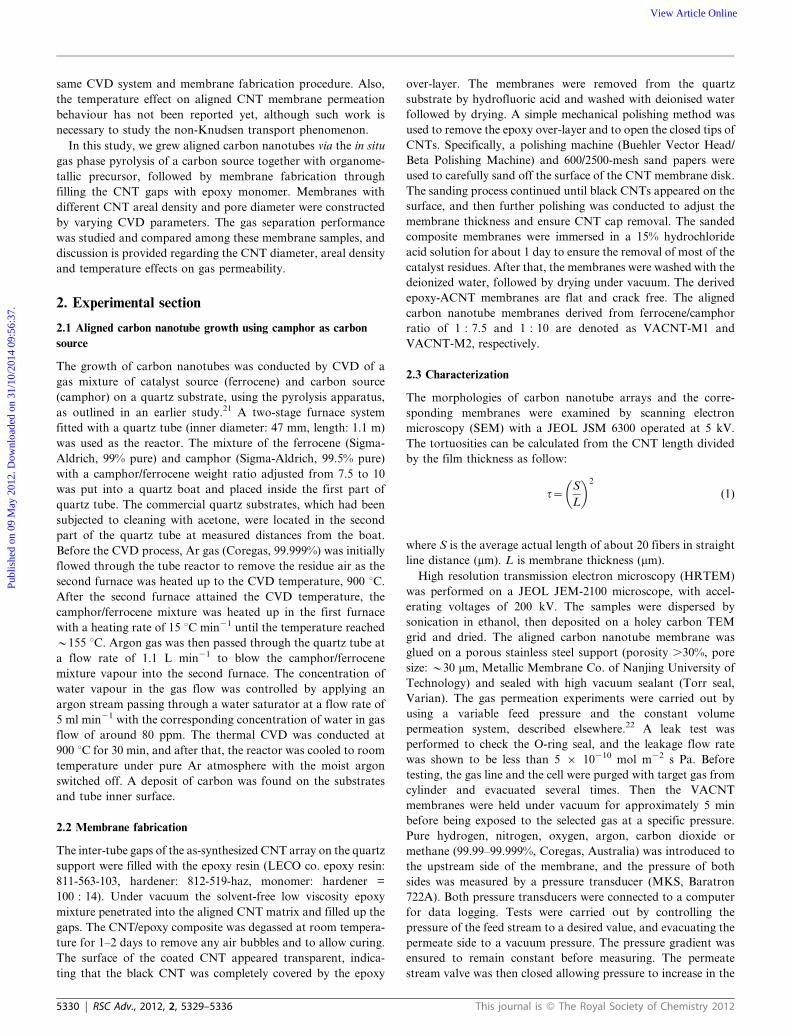
Fig. 1 shows the cross section of as-grown multi-walled CNT
arrays derived from different ferrocene concentrations. The CNT
arrays show high degree of vertical alignment and are well
packed to form a uniform carpet-style forest with a thickness of
y500 and y215 mm for a camphor/ferrocene ratio of 7.5 and 10,
respectively. High magnification images are also given in Fig. 1b
and Fig. 1d, showing that most of carbon nanotubes are parallel
to each other and quite straight. Near-unity tortuosities were
estimated to be 1.1 ¡ 0.1 and 1.3 ¡ 0.3 by eqn (1) for two
VACNTs samples. The density of VACNT arrays is y1010
nanotubes cm22, and varies with the mass ratio of camphor to
ferrocene. The ferrocene quantity in the mixed precursor
determines the Fe catalyst concentration in the mixed precursor
gases and therefore leads to variation of both Fe catalyst density
and Fe nanoparticle sizes on the substrate. Higher ferrocene
concentrations result in denser catalyst packing and straighter
nanotubes but larger catalyst particles due to nano-Fe particle
agglomeration.23
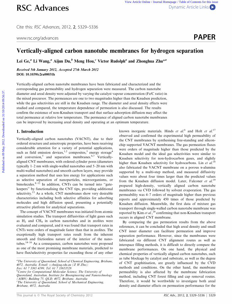
The typical TEM images of CNTs derived from different
camphor/ferrocene ratios are shown in Fig. 2. Most of the tubes
are quite straight and continuously hollow, but some bamboo
structures and bridged tube walls can also be observed. As can be
seen in Fig. 2a, CNTs grown from higher ferrocene concentra-
tion (camphor/ferrocene = 7.5) have larger average inner
diameter (7.7 nm), while a smaller inner diameter of around
5.1 nm was obtained by reducing the ferrocene amount
(camphor/ferrocene = 10) in Fig. 2b. The increase of inner
diameter size can be attributed to the larger Fe catalyst particle
size.24 In addition, some thin tubes with less than 2 nm diameter
can also be seen among the aligned tubes due to non-uniform
catalyst distribution.
3.2 Characterizations of vertically aligned CNT membranes
As reported in the references, VACNT membranes have
previously been formed by filling the carbon nanotube interspace
with a polymer or ceramic matrix, such as polystyrene,6,18
polysulfone20 and silicon nitride.17 In this study, the as-
synthesized aligned carbon nanotube arrays are relatively thick
(.200 mm) and thus generate larger diffusion resistance for
polymer filling. Consequently, to achieve complete filling of the
CNT interspaces smaller monomer molecules are preferred,
instead of filling using larger molecules. In this work, the dense
membranes were fabricated by filling with epoxy, which has been
shown to be a practicable route to fill super long VACNT
arrays.25 Freestanding membranes are produced after the quartz
Fig. 1 Cross-sectional morphology of aligned CNT arrays (a,b:
camphor/ferrocene = 7.5, c,d: camphor/ferrocene = 10).
Fig. 2 HRTEM image of carbon nanotubes derived from various
camphor/ferrocene mass ratio (a: 7.5, b:10).
This journal is � The Royal Society of Chemistry 2012 RSC Adv., 2012, 2, 5329–5336 | 5331
Publ
ishe
d on
09
May
201
2. D
ownl
oade
d on
31/
10/2
014
09:5
6:37
. View Article Online
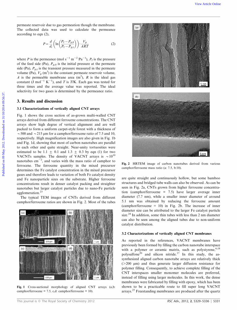
substrate base is removed. The typical cross-section and surface
morphologies of the CNT membrane are shown in Fig. 3. The
thickness of the VACNT-M2 membrane is around 105 mm
(Fig. 3a) with the aligned CNTs intact. Noting that the
membrane thickness of the original ACNT arrays is y215 mm
(Fig. 1b), it is apparent that mechanical polishing removes
almost half of the carbon nanotube carpet. The process ensures
that both ends of the CNTs are opened and the nano-scale
channels of carbon nanotubes are exposed. The thickness
variation and polished fragments can also be observed in
Fig. 3a, which are attributed to the surface roughness on
membrane caused by the mechanical polishing. Fig. 3b shows
that a dense structure is formed by polymer filling into the CNT
spacing, i.e. the nanotube carpet is fully impregnated without
voids. Some highly curved CNTs apparent in Fig. 3b are caused
by cutting. Mechanical polishing does not affect the membrane
integrity and dense structure, only leading to higher surface
roughness, as can be seen in Fig. 3c.
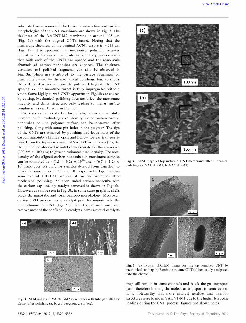
Fig. 4 shows the polished surface of aligned carbon nanotube
membranes for evaluating areal density. Some broken carbon
nanotubes on the polymer surface can be observed after
polishing, along with some pin holes in the polymer. The tips
of the CNTs are removed by polishing and leave most of the
carbon nanotube channels open and hollow for gas transporta-
tion. From the top-view images of VACNT membranes (Fig. 4),
the number of observed nanotubes was counted in the given area
(300 nm 6 300 nm) to give an estimated areal density. The areal
density of the aligned carbon nanotubes in membrane samples
can be estimated as y(1.1 ¡ 0.2) 6 1010 and y(6.7 ¡ 1.2) 6109 nanotubes per cm2, for samples derived from camphor to
ferrocene mass ratio of 7.5 and 10, respectively. Fig. 5 shows
some typical HRTEM pictures of carbon nanotubes after
mechanical polishing. An open ended carbon nanotube with
the carbon cap and tip catalyst removed is shown in Fig. 5a.
However, as can be seen in Fig. 5b, in some cases graphitic shells
block the nanotube and form bamboo morphology. Moreover,
during CVD process, some catalyst particles migrate into the
inner channel of CNT (Fig. 5c). Even though acid wash can
remove most of the confined Fe catalysts, some residual catalysts
may still remain in some channels and block the gas transport
path, therefore limiting the molecular transport to some extent.
It is noteworthy that more catalyst residues and bamboo
structures were found in VACNT-M1 due to the higher ferrocene
loading during the CVD process (figures not shown here).Fig. 3 SEM images of VACNT-M2 membranes with tube gap filled by
Epoxy after polishing (a, b: cross-section; c: surface).
Fig. 4 SEM images of top surface of CNT membranes after mechanical
polishing (a: VACNT-M1, b: VACNT-M2).
Fig. 5 (a) Typical HRTEM image for the tip removed CNT by
mechanical sanding (b) Bamboo structure CNT (c) iron catalyst migrated
into the channel.
5332 | RSC Adv., 2012, 2, 5329–5336 This journal is � The Royal Society of Chemistry 2012
Publ
ishe
d on
09
May
201
2. D
ownl
oade
d on
31/
10/2
014
09:5
6:37
. View Article Online
3.3 Gas permeation performance of vertically aligned CNT
membranes
Table 1 shows the hydrogen permeances for VACNT membranes
at different preparation stages. Compared to the VACNT
membranes, much higher permeability of the porous stainless
steel support indicates that the diffusion resistance of the support
can be neglected. The epoxy filled VACNT membranes without
polishing possess CNTs with closed ends and covered with
polymer, and therefore show very low hydrogen permeance as
expected, around 10210 mol m22 s21 Pa21. This means that there
are essentially no channels through the membranes, and the
permeance reflects gas diffusion in the epoxy polymer or perhaps
tiny permeance from cross-membrane leakage. This confirms
that the membranes are defect-free and the CNT gaps are fully
filled, which is consistent with SEM images (Fig. 3). After
reducing membrane thickness and removing the epoxy over-layer
as well as the closed CNT tips by mechanical polishing, the
hydrogen permeance increases dramatically by around two
orders of magnitude. This dramatic permeance increment proves
that gas diffusion resistance of polymer layer is much higher than
carbon nanotube channel. Further permeance improvement is
observed after acid washing, which means that catalyst residues
are cleaned by acid and more unimpeded channels are provide
for gas transportation.
The parameters of the VACNT membranes from different
CVD conditions were given in Table 2 for calculating the
Knudsen permeance and for comparison. The mean free path of
gases at room temperature (y67 nm) is almost one order of
magnitude larger than the pore diameter of the given VACNT
membranes (5y8 nm). Therefore, the gas transportation
through the VACNT membranes is expected to be in the
Knudsen range. The calculated areal porosity in this study is
similar to the doubled-walled VACNT membranes (5.0 61023)17 and multi-walled VACNT membranes (1.0 6 1023)7
from CVD synthesis, but is higher than the VACNT membrane
grown from porous alumina support (6.2 6 1024)18 and
membrane fabricated by filtration (7.9 6 1024)20 yet lower than
high dense VACNT membrane (0.21).19
The permeability and diffusivity in Knudsen flow range can be
estimated from eqn (3,4)7,18
PK~2er
tRTL
8RT
pM
� �12
(3)
DK~2
3
� �8RT
pM
� �12
r (4)
where PK is the Knudsen permeability (mol m22 s21 Pa21), DK is
Knudsen diffusivity (m2 s21), M is molecular weight of penetrant
(kg mol21), R is the universal gas constant (J mol21 K21), T is
absolute T/K, r is the inner diameter of CNT (m), L is the
membrane thickness (m), e is the porosity and t is the tortuosity.
The permeance enhancement factor (a) can be calculated by
the following equation:
a~P
PK(5)
Membranes with high separation performance should not
display any viscous flow, in which case the permeability is
independent of the feed pressure (eqn (3)). When viscous flow
does occur, the permeability increases with increasing pressure
gradient.26 Argon gas permeation tests under various pressure
gradients were carried out to examine polymer filling and
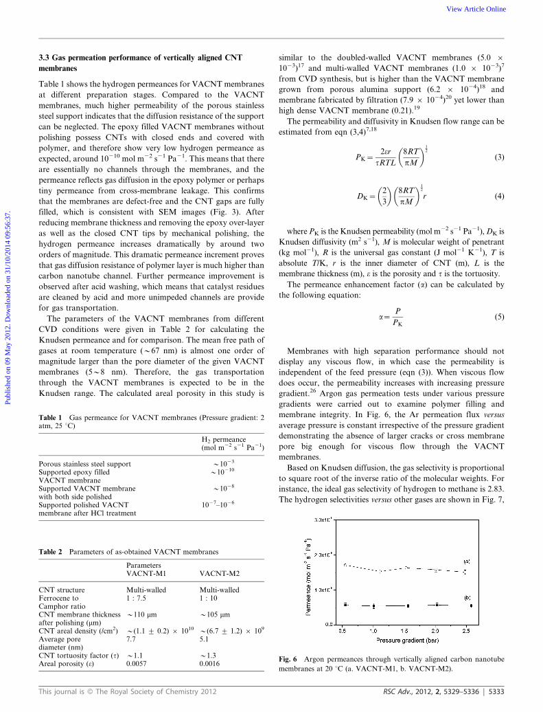
membrane integrity. In Fig. 6, the Ar permeation flux versus
average pressure is constant irrespective of the pressure gradient
demonstrating the absence of larger cracks or cross membrane
pore big enough for viscous flow through the VACNT
membranes.
Based on Knudsen diffusion, the gas selectivity is proportional
to square root of the inverse ratio of the molecular weights. For
instance, the ideal gas selectivity of hydrogen to methane is 2.83.
The hydrogen selectivities versus other gases are shown in Fig. 7,
Table 1 Gas permeance for VACNT membranes (Pressure gradient: 2atm, 25 uC)
H2 permeance(mol m22 s21 Pa21)
Porous stainless steel support y1023
Supported epoxy filledVACNT membrane
y10210
Supported VACNT membranewith both side polished
y1028
Supported polished VACNTmembrane after HCl treatment
1027–1026
Table 2 Parameters of as-obtained VACNT membranes
ParametersVACNT-M1 VACNT-M2
CNT structure Multi-walled Multi-walledFerrocene toCamphor ratio
1 : 7.5 1 : 10
CNT membrane thicknessafter polishing (mm)
y110 mm y105 mm
CNT areal density (/cm2) y(1.1 ¡ 0.2) 6 1010 y(6.7 ¡ 1.2) 6 109
Average porediameter (nm)
7.7 5.1
CNT tortuosity factor (t) y1.1 y1.3Areal porosity (e) 0.0057 0.0016
Fig. 6 Argon permeances through vertically aligned carbon nanotube
membranes at 20 uC (a. VACNT-M1, b. VACNT-M2).
This journal is � The Royal Society of Chemistry 2012 RSC Adv., 2012, 2, 5329–5336 | 5333
Publ
ishe
d on
09
May
201
2. D
ownl
oade
d on
31/
10/2
014
09:5
6:37
. View Article Online
in which the measured values are scattered around the Knudsen
selectivity regime. On the other hand, for Knudsen diffusion,
selectivity should be independent of temperature, so selectivity
changes at different temperatures indicate the presence of
diffusion processes apart from Knudsen, such as surface
diffusion. Surface diffusion along carbon nanotube walls may
play a significant role in gas transportation and result in
deviation from the ideal Knudsen gas separation behaviours.15,27
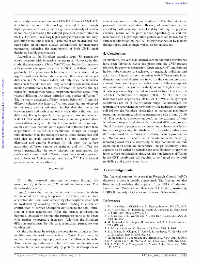
The membrane permeance and enhancement factor over
Knudsen diffusion for each gas are shown in Fig. 8. Based on
the enhancement factor (eqn (5)), the permeation fluxes are much
higher than the Knudsen diffusion, which confirms that the gas
transport happens primarily through the carbon nanotube
channel rather than the dense polymer matrix. In Fig. 8c,d, the
permeation enhancement phenomenon is consistent with experi-
mental observations of carbon nanotube membranes reported
previously.4,6,7,17–19 The enhancement factors are 30–60 for
VACNT-M1 and 30–80 for VACNT-M2 at room temperature.
Such high diffusion enhancements can be attributed to the
smooth interior channels in the VACNT membranes in which
molecular collisions do not have any backscattering, and keep all
forward momentum upon reflections down the CNT channels.7
The skate-down gas molecular route along the tube channel
differs from randomly-scattered Knudsen diffusion and therefore
generates very high flow velocity.15 This specular momentum
transfer significantly increases the diffusivities, to an extent much
higher than kinetic theory.14,28,29 Comparing the enhancement
factors for the two membranes (Fig. 8c and d), the smaller-sized
VACNT-M2 exhibits a slightly higher enhancement factor than
VACNT-M1 with larger tube channels. This difference in
permeance enhancement is most likely related to the various
catalyst residue amounts in the two membrane samples. Since
Fig. 7 Hydrogen selectivity relative to other gases (pressure gradient:
2 atm).
Fig. 8 (a, b) Permeance of gases through different aligned carbon
nanotube membranes and (c, d) enhance factor over Knudsen diffusion
for each gas.
5334 | RSC Adv., 2012, 2, 5329–5336 This journal is � The Royal Society of Chemistry 2012
Publ
ishe
d on
09
May
201
2. D
ownl
oade
d on
31/
10/2
014
09:5
6:37
. View Article Online
more catalyst residue is found in VACNT-M1 than VACNT-M2,
it is likely that more tube blockage occurred. Hence, though
higher permeance arises by increasing the areal density of carbon
nanotubes by increasing the catalyst precursor concentration in
the CVD process, a resulting higher catalyst residue amount may
also bring more tube blockage. Therefore, it can be deduced that
there exists an optimum catalyst concentration for membrane
permeance, balancing the requirements of both CNTs areal
density and unblocked channels.
According to the Knudsen equation (eqn (3)) permeance
would decrease with increasing temperature. However, in this
study, the permeances of both VACNT membranes first increase
with increasing temperature up to 50–60 uC, and then drop off
gradually. This permeance behaviour with temperature, taken
together with the enhanced diffusion rate, illustrates that the gas
diffusion in CNT channels does not fully obey the Knudsen
diffusion law and there are likely other diffusion mechanisms
making contributions to the gas diffusion. In general, the gas
transport through mesoporous membrane materials arises from
viscous diffusion, Knudsen diffusion and surface diffusion.30
The thermally activated diffusion process below 60 uC and the
different enhancement factors of various gases that are observed
in this study and in reference,7 implies that the interaction
between gases and carbon nanotube walls affects the total gas
diffusivity. It may be speculated that gas adsorption on the inner
wall of CNTs could occur at low temperature and generate slow
surface diffusion layers. The effect of this surface diffusion layer
on bulk diffusion becomes more significant in thinner tubes than
larger tubes. In the VACNT membranes, though the average
tube diameter is in the mesopore range, some micropores still
exist due to small diameter tubes (,2 nm), carbon layer
distortion and catalyst blockage. In this case, the surface
adsorption diffusion cannot be neglected and will affect the
overall permeability. In some microporous membranes, the
surface-adsorption-based diffusion shows the activation process
and follows an Arrhenius-type mechanism.31,32 The activated
permeation can be described by
P0i ~P�i e{ E
RT (6)
Piu is the measured pure gas permeance through the
membrane, Pi* is the value of Piu at infinite temperature, E is
the activation energy.
Eqn (6) shows that the thermal activated permeance tends to
be enhanced with rising temperature. However, such surface-
adsorption diffusion is also affected by physisorption, which will
be weakened by elevating temperature, leading to a smaller
contribution of surface-adsorption diffusion to the total diffu-
sion at higher temperature. After the surface physisorption
become attenuated by heating, the permeance starts to go down
with further temperature increases, following the Knudsen
diffusion mechanism. In this case, a maximal permeance can
be observed.
On the other hand, by reducing the pore size or through surface
modification, the surface-adsorption diffusion layers may be
induced to occupy a larger proportion of the diffusion channels.
This dominating surface-adsorption diffusion mechanism can
enhance the separation selectivity by preferential adsorption of
certain components on the pore surfaces.32 Therefore, it can be
proposed that the separation efficiency of membranes can be
altered by both pore size control and by tailoring the physico-
chemical nature of the pore surface. Specifically, a VACNT
membrane with higher separation performance can be realized by
surface modification on the CNT interior channels or by making
thinner tubes, such as single-walled carbon nanotubes.
4. Conclusions
In summary, the vertically-aligned carbon nanotube membranes
have been fabricated via a gas phase catalytic CVD process
followed by epoxy encapsulation. Open-ended CNT and exposed
hollow tube channels are achieved by mechanic polishing and
acid wash. Aligned carbon nanotubes with different tube inner
diameter and areal density are tuned by the catalyst precursor
content. Based on the gas permeation results of the correspond-
ing membranes, the gas permeability is much higher than the
Knudsen permeability, the enhancement factors of small-sized
VACNT membranes are higher (30–80, 20 uC) than the
membrane with larger tubes (30–60, 20 uC). While the hydrogen
selectivities are all in the Knudsen range. To investigate the
temperature dependence of permeability, the hydrogen selectivity
still follows the Knudsen predication as increasing membrane
operation temperature, while the permeance peaks around 50–60
uC. This deviated phenomenon confirms the existence of non-
Knudsen transport and thermally activated diffusion process.
The differences of permeance increment and enhancement factor
for various gases may be attributed to the surface adsorption
diffusion. Based on the results in this study, it can be proposed as
an effective way to achieve better membrane performance by
increasing areal density, decreasing catalyst contamination and
operating at an optimum temperature. The gas selectivity is also
expected to be varied by reducing the tube diameter or applying
inner surface modification. However, the non-Knudsen diffusion
in the CNT membranes still requires to be figured out by both
modelling and experimental work.
Acknowledgements
The financial support by Australian Research Council (ARC)
discovery project is greatly appreciated. The first author also
likes to acknowledge the support from IPRS (Endeavour
International Postgraduate Research Scholarship, Australia),
UQRS (University of Queensland Research Scholarship).
References
1 W. A. de Heer, A. Chaelain and D. Ugarte, Science, 1995, 270, 1179.2 W. A. de Heer, J. M. Bonard, K. Fauth, A. Chatelain, D. Ugarte and
L. Forro, Adv. Mater., 1997, 9, 87.3 E. J. Garcia, B. L. Wardle and A. John Hart, Composites, Part A,
2008, 39, 1065.4 M. Majumder, N. Chopra, R. Andrews and B. J. Hinds, Nature,
2005, 438, 44.5 A. Misra, J. Giri and C. Daraio, ACS Nano, 2009, 3, 3903.6 B. J. Hinds, N. Chopra, T. Rantell, R. Andrews, V. Gavalas and
L. G. Bachas, Science, 2004, 303, 62.7 M. Majumder, N. Chopra and B. J. Hinds, ACS Nano, 2011, 5, 3867.8 S. A. Miller and C. R. Martin, J. Am. Chem. Soc., 2004, 126, 6226.9 S. A. Miller, V. Y. Young and C. R. Martin, J. Am. Chem. Soc., 2001,
123, 12335.
This journal is � The Royal Society of Chemistry 2012 RSC Adv., 2012, 2, 5329–5336 | 5335
Publ
ishe
d on
09
May
201
2. D
ownl
oade
d on
31/
10/2
014
09:5
6:37
. View Article Online

10 A. I. Lopez-Lorente, B. M. Simonet and M. Valcarcel, Anal. Chem.,82, 5399.
11 B. Suarez, Y. Moliner-Martinez, S. Cardenas, B. M. Simonet and M.Valcarcel, Environ. Sci. Technol., 2008, 42, 6100.
12 A. S. Brady-Estevez, S. Kang and M. Elimelech, Small, 2008, 4, 481.13 M. Majumder, N. Chopra and B. J. Hinds, J. Am. Chem. Soc., 2005,
127, 9062.14 D. M. Ackerman, A. I. Skoulidas, D. S. Sholl and J. K. Johnson,
Mol. Simul., 2003, 29, 677.15 A. I. Skoulidas, D. M. Ackerman, J. K. Johnson and D. S. Sholl,
Phys. Rev. Lett., 2002, 89, 185901.16 A. I. Skoulidas, D. S. Sholl and J. K. Johnson, J. Chem. Phys., 2006,
124, 054708.17 J. K. Holt, H. G. Park, Y. Wang, M. Stadermann, A. B. Artyukhin,
C. P. Grigoropoulos, A. Noy and O. Bakajin, Science, 2006, 312,1034.
18 W. Mi, Y. S. Lin and Y. Li, J. Membr. Sci., 2007, 304, 1.19 M. Yu, H. H. Funke, J. L. Falconer and R. D. Noble, Nano Lett.,
2009, 9, 225.
20 S. Kim, J. R. Jinschek, H. Chen, D. S. Sholl and E. Marand, NanoLett., 2007, 7, 2806.
21 M. Kumar and Y. Ando, Chem. Phys. Lett., 2003, 374, 521.22 L. Ge, Z. Zhu and V. Rudolph, Sep. Purif. Technol., 2011, 78, 76.23 M. A. Signore, A. Rizzo, R. Rossi, E. Piscopiello, T. Di Luccio, L.
Capodieci, T. Dikonimos and R. Giorgi, Diamond Relat. Mater.,2008, 17, 1936.
24 C. L. Cheung, A. Kurtz, H. Park and C. M. Lieber, J. Phys. Chem. B,2002, 106, 2429.
25 F. Du, L. Qu, Z. Xia, L. Feng and L. Dai, Langmuir, 2011, 27, 8437.26 Y. S. Lin and A. J. Burggraaf, J. Membr. Sci., 1993, 79, 65.27 C. Matranga, B. Bockrath, N. Chopra, B. J. Hinds and R. Andrews,
Langmuir, 2006, 22, 1235.28 G. Arya, H.-C. Chang and E. J. Maginn, Mol. Simul., 2003, 29, 697.29 G. Arya, H.-C. Chang and E. J. Maginn, Phys. Rev. Lett., 2003, 91, 026102.30 E. L. Cussler, Diffusion: Mass transfer in fluid systems, Cambridge
Univ Pr, 1997.31 A. B. Fuertes, J. Membr. Sci., 2000, 177, 9.32 M. B. Rao and S. Sircar, J. Membr. Sci., 1993, 85, 253.
5336 | RSC Adv., 2012, 2, 5329–5336 This journal is � The Royal Society of Chemistry 2012
Publ
ishe
d on
09
May
201
2. D
ownl
oade
d on
31/
10/2
014
09:5
6:37
. View Article Online