version issue date revision description 2.0 2-aug-2016 - 2.2 11 … · version issue date revision...
TRANSCRIPT

1

2
Version Issue Date Revision Description
2.0 2-Aug-2016 - Complete rewrite for new release of Service Portal
2.2 11-May-2017 - Add Section 7.5, 7.6, 7.7 for template, ISO and volume management
- Add Section 9 Monitoring guide
3
Table of Contents 1 Overview ............................................................................................................................. 6
2 Getting Started .................................................................................................................... 6
3 Cloud Portal ........................................................................................................................ 6
3.1 First time sign in ............................................................................................................ 6
3.2 Sign in Cloud Portal ...................................................................................................... 9
3.3 Forgot password ......................................................................................................... 10
3.4 Using your Backup Code to Sign In ............................................................................ 11
3.5 Set up 2FA on a new phone ....................................................................................... 12
4 Dashboard ........................................................................................................................ 15
4.1 User Profile ................................................................................................................. 16
5 Launch .............................................................................................................................. 17
6 Instance ............................................................................................................................ 20
6.1 Listing all VMs ............................................................................................................ 20
Change Grouping Display and Search ................................................................... 20
VM Operations on Instance Listing page ............................................................... 22
6.2 VM Details page ......................................................................................................... 22
Overview Tab ........................................................................................................ 23
Volumes Tab ......................................................................................................... 25
VM Snapshot Tab .................................................................................................. 27
6.3 VM Operation ............................................................................................................. 28
Stop VM ................................................................................................................. 28
Start VM ................................................................................................................ 29
Reboot VM ............................................................................................................ 29
Terminate VM ........................................................................................................ 30
Remote Console .................................................................................................... 32
Change VM Display Name ..................................................................................... 32
VM Password ........................................................................................................ 33
Resize VM (Compute Offering) .............................................................................. 34
Manage VM Network Interface .............................................................................. 35
Manage Volume ................................................................................................. 39
Manage VM Snapshot ....................................................................................... 44
Attach / Detach ISO ........................................................................................... 45
7 Resource ........................................................................................................................... 47
7.1 Resource Pools .......................................................................................................... 47

4
7.2 Regions ...................................................................................................................... 47
7.3 Usage & Limits............................................................................................................ 47
7.4 Networking .................................................................................................................. 48
VPC Network ......................................................................................................... 48
Flat Network .......................................................................................................... 61
Public IP ................................................................................................................ 70
7.5 Templates ................................................................................................................... 73
Upload Templates ................................................................................................. 73
Download Templates ............................................................................................. 74
Delete Templates .................................................................................................. 75
7.6 Volumes ..................................................................................................................... 75
7.7 ISOs ........................................................................................................................... 76
8 Settings ............................................................................................................................. 78
8.1 My User Profile ........................................................................................................... 78
8.2 My Account ................................................................................................................. 79
My Account - General ............................................................................................ 79
My Account - Preferences...................................................................................... 79
8.3 Users .......................................................................................................................... 81
Add New User ....................................................................................................... 81
9 Monitoring ......................................................................................................................... 84
9.1 Login the Monitoring tool ............................................................................................. 84
9.2 View your device information & detail ......................................................................... 85
Launch more status & resource usage................................................................... 85
View the performance data by chart ...................................................................... 85
9.3 Manage your device monitoring setting ....................................................................... 86
Edit the Device setting ........................................................................................... 86
Suspend device monitoring .................................................................................... 88
9.4 Review or download historic data ............................................................................... 89
9.5 Add report (Support html format only) ......................................................................... 91
Create the report ................................................................................................... 92
Select Sensors Manually ....................................................................................... 96
9.6 Manage your saved report .......................................................................................... 97
View and run your saved report ............................................................................. 97
Delete your report .................................................................................................. 98
Edit your report ...................................................................................................... 99
Clone your report ................................................................................................. 100
9.7 VM resource warning /error status & email notification.............................................. 101
Setup the warning /error status ............................................................................ 101

5
Setup email notification ........................................................................................ 103

6
1 Overview HKBN Infinite Server Cloud Portal is an advanced cloud management platform which offers an easy-to-use experience for delivering self-service Infrastructure-as-a-Service to customers. Users can do all of the following through the Portal: manage their resource pools, perform VM operations, manage user accounts, setup roles & permissions, etc.
2 Getting Started After subscribing Infinite Server service, customer’s admin contact will receive an email with link and instruction to activate the account. After account activation, customer will receive a ‘Welcome Email’ with all the information of subscribed services including the login credential of the Cloud Portal, where customer can manage its cloud services.
All required VM & VAS on supplementary form submitted by customer, including VPC and vLANs, were pre-provisioned and ready for use when the welcome email is received. Customer could manage the subscribed cloud services anytime via the cloud portal when needed.
3 Cloud Portal
URL for Login: https://iserver.hkbnes.net/ Username: <Remark: Customer will receive this information in welcome email> Password: <Remark: Customer will receive this information in welcome email> 2 Factor Authentication Token: <Remark: Customers will need to register their smartphone as 2
Factor Authentication token>
Note: For 2 factor authentication, users will need to install Google Authenticator App on their smart phone. Apple IOS, Andriod & Blackberry are supported.
3.1 First time sign in
1. Go to Login page.

7
2. Enter your Username or Email.
3. Enter Password.
4. Click Login button.
5. If you have entered your Username and Password correctly, you should see the
following screen to enable Two-Step Verification.
6. Google Authenticator App is used for 2FA, click the Google Authenticator App
button.
7. You should see the Enable Two-Step Verification page.

8
8. Install Google Authenticator App on your smart phone. For app installation procedure,
please click the option corresponding to your mobile operating system.
Apple Store
Google Play Store
9. Open your Google Authenticator App on your smart phone.
10. Use your Google Authenticator App to scan the QR code shown on the Enable Two-
Step Verification page.

9
11. Enter the 6-digit code generated by your Google Authenticator App. Please note that
the code is refreshed in every 30 seconds.
12. Click Submit button.
13. If the code is correct, you will be redirected to the Manage Two-Step Verification page.
14. In the Manage Two-Step Verification page, you should see 5 Single-use Backup
Codes. Each backup-code can only be used for one time. These Backup Codes should
be saved for emergencies, such as when you lose your phone and need to access to
App360. After you have logged in, you can re-enable Two-Step Verification with your
new phone.
Notes : In case you do not have your smartphone and the Single-use Backup Codes with you, please contact HKBN hotline 128180 to raise request for account reset.
3.2 Sign in Cloud Portal
1. Go to Login page.

10
2. Enter your Username or Email.
3. Enter Password.
4. Click Login button.
5. If you have entered your Username and Password correctly, you should see the
following screen to enter Account Verification code.
6. Enter the 6-digit code generated by your Google Authenticator App. Please note that
the code renews every 30 seconds.
7. Click Sign In button.
8. If the code is correct then you should see the Dashboard page.
3.3 Forgot password
If you have forgotten your password, you can click the Forgot password link on the login page and follow the steps to reset your password.
Reset Password steps:
1. Go to the Login page then click the Forgot password link.
2. You should see the Reset Password page. Please enter your Username or Email and
click the Send Verification email button.

11
3. After clicking the button, you should see a message showing that the Reset Password
link has been sent to your email.
4. Check your email and click the Reset Password link.
5. Your browser will open the Reset Your Password page.
6. Enter your new password twice and click the Reset Password button to reset your
password. Now you can login with your new password.
3.4 Using your Backup Code to Sign In
1. Go to Login page.
2. Enter your Username (or Email) and Password, then click Sign In button.
3. Click Unable to receive verification code link.

12
4. Enter one of your backup codes then click Sign In button.
3.5 Set up 2FA on a new phone
When you want to set up 2FA on a new phone, you will need to use your new Google Authenticator app to scan the QR code again. Here are the steps:
1. Login to Cloud Portal.
2. From the top nav bar, click Settings then click the My User Profile link.
3. Click Manage Settings in the Edit My User Profile page under the General tab.

13
4. Now you are on the Manage Two-Step Verification page.
5. Click the Reset two-step verification button then you should see the following Enable
Two-Step Verification page.

14
6. Click the Google Authenticator App button.
7. You should see the Enable Two-Step Verification page.
8. Please repeat step 8 to 14 in Section 4.1 - First time Sign In.

15
4 Dashboard The Dashboard is the landing page upon login. It consists of the following components:
● Quick Launch:
○ User can select “New Order” to jump to the Launch VM page for VM deployment.
● Cloud VM Stats:
○ User can view OS distribution for all and individual cloud.
○ User can view VM state distribution for all and individual cloud.
● Resource Usage & Limit
○ On a per resource pool basis, user can view resource utilization and limits
(quota).
● Event Logs
○ All activities within a tenant account are listed.
● Job Pending for My Approval
○ All jobs requiring your approval are listed.
● My Job Status
○ All tasks performed by your account are listed.
● Notification Center (orange arrow button at bottom right corner)
○ It will pop-up automatically where there is any background job started, or you can
click the button manually to see the details.

16
4.1 User Profile
Click the User Profile icon in upper right corner to access:
My User Profile – for updating user personal information, changing password, managing 2FA token and accessing history. Please refer to Session 8.1 for more details.
Jobs – show all request, approved & pending for approval jobs (if approval chain is enabled)
Logout – to logout the cloud portal session

17
5 Launch
User can launch a VM (virtual server) from the Cloud Portal by clicking the Launch icon
on the Top Nav menu. User will be redirected to the Resource Order page.
In the Resource Order page, user can design the VM instance by providing the following info:
Workload & Life Cycle: These are optional fields. The purpose of these tags are for user to list all VMs filtered by the Workload or Life Cycle value. Users are recommended to group VMs into different Workload & Life Cycles for easy management.
Instance name: User can enter a name to identify a VM instance.
Hostname: This is an optional field. Hostname is the server name and must be
unique within the same network. If this field is left empty, Cloud Portal will
generate a name for this field automatically.
Lifetime: User can set the lifetime of a VM so it can be automatically terminated
to avoid unnecessary charges.
Resource pool: A list of active cloud targets for user to select for deployment.

18
Location: If a cloud target consists of multiple locations, a list will be provided for
selection.
Zone: Similar to Location, if a location consists of multiple zones, a list will be
provided for selection.
Launch From: VM can be launched from Template, ISO or Volume Snapshot.
Template: When launching from Template, select one of the available template from
the drop down list.
Compute Offering: A predefined list of VM sizes for users to select.
Network: User can select existing Network or create new one from the Network drop down list.
The Internal IP field is optional, it will be assigned by DHCP if this field is blank.
Optionally, user can add more than one network for this VM by clicking the button. Please note the first selected network will be set as default if more than one networks is added for this VM. Note: VPC is pre-provisioned and configured by HKBN, customers are recommended not to add/delete the VPC by themselves on the portal.
Data volume: User can also add additional data volumes to the VM for extra
storage space.
The Volume name is a required field for adding a new data volume. Also, user must select one of the Disk Offerings and set the size of this data volume.
Tags (optional): User can add tag(s) for this VM. A tag is a key-valued pair.
Click the button to add more tags.

19
User can launch more than one server (VM) at the same time on the Resource Order page. This Resource Order page will update resource utilization in the Resource Usage & Limit section in real time so user can determine whether there are sufficient resources for this deployment.
Click the green Provision button to launch.
After clicking the Provision button, you should see a Terms and conditions dialog box. Click I have read and agreed the Terms and Conditions check box after reading it. Then click the green Agree button.
You will be redirected to the Instance listing page for monitoring the server launch. The Notification Center will pop-up from the bottom of the page to show launch progress.
You can click the notification text to see the details or click the button to hide the notification center.

20
6 Instance
The Instance Menu shows a list of deployed VMs with that can be drilled down into for more information. The display list can be grouped by Author, Cloud, Life Cycle, Resource Pool or Workload. User can also search VMs by attributed names or tags. Next to each VM, there is additional information like the VM status, name, zone, offering, location and provision time as well as actions. User can click the VM icon or Instance Name to enter the Server Detail page for detailed server information and change options.
6.1 Listing all VMs
1. From the Top Nav menu, click Instance icon. The Instance Listing page shows all
VMs.
2. Users can mouse over the VM state icon to see real-time VM status. For example:
Change Grouping Display and Search
Click the Group by Cloud drop down menu to show VMs in different groups.

21
VMs can be grouped by Author of the VM, Cloud, Life Cycle, Resource Pool and Workload. The
following example shows VMs grouped by Workload.
You can search for VMs by clicking the search text box, select an attribute type and enter the
keywords:
It shows a list of searchable attributes and tags. The following example searched for VM display
name result:

22
VM Operations on Instance Listing page VM Reboot, Stop, Start and Terminate can all be performed on this page by clicking the Action drop down menu:
6.2 VM Details page
Click View under Action button or Instance Name on Instance Listing page to view the VM Details.
The VM Details page shows VM information and can perform actions on the VM. The information about VM includes: VM names, size, OS, state, lifetime policy, network interfaces, VM password, created time, created by, tags, volume and VM snapshots. The VM Details page provides the following actions to manage the VM:
● Start, Stop, Reboot and Terminate VM.
● Access Remote Console of the VM.
● Reset VM password (if VM is launched from supported template).
● Show / Hide last known VM password.
● Edit VM display name.
● Change Compute Offering (resize VM).
● Attach and detach ISO.
● Change VM lifetime policy.

23
● Add / remove network interfaces.
● Set default network interface.
● Acquire public IP for the VM.
● Add / Remove tags of the VM.
● View, add new, attach existing and detach volume.
● View, create, delete and schedule volume snapshot.
● Create volume, create image and restore VM from volume snapshot.
● View, create and delete VM snapshot.
● Restore VM from VM snapshot.
Notes : Customers are highly recommended to change the VM password after resetting.
Overview Tab The VM Overview Tab provides detailed configurations and access info. Users can modify server configurations by clicking the blue action buttons.
1. Reset Password
Click the Reset Password button to reset the VM password. Click Submit to confirm.

24
2. Compute Offering: Resize
Click the Resize button to change the server flavor. A dialog box will appear showing a list of Offering. Please note changing to a smaller server size is not advisable and certain cloud targets and operating systems may require server reboot to activate. Select a new Offering and click Resize.
3. ISO Attachment: Attach
Click the Attach button to attach an ISO image. A dialog box will appear showing a list of available ISO images. These images have to be uploaded in advance. Select the ISO image and click Attach to confirm.
4. Lifetime Policy: Update
Click the Update button to change VM lifetime. A dialog box will appear showing lifetime choices. The VM will be automatically terminated once the lifetime expires. The system will automatically notify the VM owner once the lifetime reaches 50%.
5. Tags: Manage

25
Click the Manage button to modify server tags. A dialog box will appear with a range of keys available for changes. User can modify the Account, Author, Life Cycle and Workload tags.
6. Network Interfaces: Add Network Interface
Click Add Network Interface button to add additional network interfaces. A dialog box will appear with a choice of available networks. Click Add Network to confirm.
7. Network Interfaces: Acquire Public IP for Static NAT
VMs are launched with private IPs to conserve public IPs. For those requiring public IPs, click the Acquire Public IP for Static NAT button to assign a public IP on this network interface. A dialog box will appear showing Terms and Conditions. To confirm, check the box and click Agree.
Volumes Tab The Volume tab allows users to manage server volumes including add, delete, attach, and detach, as well as snapshot management. The following diagram illustrates the volume and snapshot operation user interface.

26
1. Refresh
Click the Refresh button to refresh the status of volumes.
2. Add Volume
Click the Add Volume button to add additional volumes to the VM. A dialog box will appear for user to enter:
● Volume Name
● Disk Offerings
○ Users can choose from the storage tiers: SSD, T1, T2 or T3.
● Size (GB)
3. View Snapshot
Click the View Snapshot button to view volume snapshot. A dialog box will appear to list the snapshots. Users can create volume, create image, restore VM or delete the snapshot.
4. Schedule Snapshot
Click the Schedule Snapshot button to schedule snapshot. A dialog box will appear to enter the following info:
● Schedule Basis
● Time
● Time zone
● Keep # of snapshots

27
. Current snapshot schedules will also be listed. Click Setup Policy to confirm the schedule.
VM Snapshot Tab
Users can create snapshot of the entire VM including all attached disks. This is a convenient way to create VM backup for instant recovery (e.g. backup before applying software patch).
1. Refresh
Click the Refresh button to refresh the list of snapshots.
2. Add VM Snapshot
Click the Add VM Snapshot button to create a snapshot of the entire VM including attached disks. A dialog box will appear for users to enter:
● Name
● Description
● Snapshot Memory
● Quiesce VM

28
3. Restore VM
Click the Restore VM button to restore the VM.
4. Delete
Click the Delete button to delete the VM Snapshot.
6.3 VM Operation
Stop VM There are 2 ways to stop a VM: from the Server Listing page or the VM Details page. In the Server Listing page, click the Action drop down menu and select Stop.
On the VM Details page, click the Stop button on the top right of the page.

29
Then select Yes or No depending on whether you wish to force stop the VM. Click Confirm Stop to stop the VM.
Start VM There are 2 ways to start a VM: from the Server Listing page or the VM Details page. In the Server Listing page, click the Action drop down menu and select Start.
Or go to the VM Details page and click the Start button.
Reboot VM There are 2 ways to reboot a VM: from the Server Listing page or the VM Details page. In the Server Listing page, click the Action drop down menu and select Reboot.
Or go to the VM Details page and click the Reboot Server button.

30
Terminate VM There are 2 ways to terminate a VM: from the Server Listing page or the VM Details page. In the Server Listing page, click the Action drop down menu and select Terminate:
In VM Details page, click the red Trash button:
Either way will pop-up a Terminate Server dialog box:

31
By default, the server will not be expunged. Click the red Confirm Terminate button to terminate the VM.
6.3.4.1 Expunge
If Expunge is selected, the VM will be destroyed immediately and you will not able to recover it. If Expunge is not selected, the VM will be not be destroyed immediately and the VM can be recovered within 24 hours.
You can Expunge a terminated VM in either Server Listing or VM Details page.
or
6.3.4.2 Recover VM
Click the Recover button in Server Listing or VM Details page to recover a terminated VM.
or

32
Remote Console
1. From the Top Nav menu, click the Instance icon.
2. In this Server Listing page, find your VM then click the VM name to go to the VM
Details page.
3. Click the Remote Console button.
4. Then a new browser tab will open.
Change VM Display Name
1. From the Top Nav menu, click the Instance icon.
2. In this Server Listing page, find the VM you wish to edit, then click the VM name to go
to the VM Details page.
3. Click the pen button in the Overview section.
4. Change the Display Name in the Edit Server dialog box then click the green Save
button.

33
VM Password
6.3.7.1 Reset VM Password
Some template supports password resetting after VM is launched. In some cases, you might need
to stop the VM before you are allowed to reset the VM password.
To reset VM password:
1. From the Top Nav menu, click the Instance icon.
2. In this Server Listing page, find the your VM then click the VM name to go to the VM
Details page
3. Click the Reset Password button in the Login section.
4. Click the Submit button in the Reset Password pop-up dialog box.
5. After a while, user should see a pop-up message with your new VM password.

34
6. User should also receive an email about this VM password.
6.3.7.2 Show / Hide Last Known VM Password
1. From the Top Nav menu, click on the Instance icon.
2. In this Server Listing page, find your VM then click the VM name to go to the VM
Details page.
3. Click the Show / Hide button under Login section to show or hide the VM password.
Notes : To enhance security protection, customers are recommended to change the password
after VM password is reset.
Resize VM (Compute Offering) Users can resize the VM (change compute offering) by clicking the Resize button in the VM Details page. Please note that some OS’s might require the VM to be stopped before resizing the VM.
1. From the Top Nav menu, click the Instance icon.
2. In this Server Listing page, find the VM that you want to edit, then click the VM name to
go to the VM Details page.
3. Click the Resize button under the Overview section.

35
4. Change the Offering in the Resize Compute Offering dialog box then click the Save
button.
Manage VM Network Interface
There are a few network related operations that a user can perform in the VM Details page: attaching a new network interface, removing a network interface, setting the default network, acquiring a public IP, and releasing the public IP. For more Network Operations, you can click the network name in the Network Interfaces section of the VM Details page to access the network details.
6.3.9.1 Attach New Network Interface
1. In the VM Details page, click the Add Network Interface button.

36
2. Select an available network from the Network drop down list in the Add Network
Interface dialog box.
3. Click the green Add Network button.
4. After the 2nd network interface is added, you should see:
6.3.9.2 Remove Network Interface
When there are more than one network interfaces, you can remove the non-default network by
clicking the red Remove button in Network Interface section of the VM Details page.

37
6.3.9.3 Set Default Network
When there are more than one network interfaces, you can select one to be the default interface.
Go to the VM Details page and click Set as Default button under Network Interfaces section.
6.3.9.4 Acquire Public IP
1. In the VM Details page, click Acquire Public IP for Static NAT button.
2. Agree the Terms and Conditions.
3. You should see the public IP after it acquired the IP

38
4. Also, user should receive an email about this new acquired IP.

39
Manage Volume User can manage VM volumes in the Volumes tab of the VM Details page.
In the Volumes tab, you can perform the following operations: add new data volume, attach existing data volume, detach and / or delete attached volume, take / delete / schedule volume snapshot, create volume from snapshot, create image form volume snapshot or restore VM from root volume snapshot.
6.3.10.1 Add new Data Volume
1. Click the Add Volume button in Volumes tab.
2. Click the Create New Volume button. User should see the following form:
3. Enter Volume Name, select Disk Offering, enter the data volume size, click Attach
Volume if user want to attach this volume to the current VM and click Add to create this
data volume.
4. Agree the Terms and Conditions.
5. A new data volume is created and user should receive an email about this volume.
6.3.10.2 Attach Existing Data Volume
1. Click the Add Volume button in Volumes tab.
2. Click the Attach Existing Volume button. User should see the following form.

40
3. Select Available Volume then click Attach button.
6.3.10.3 Detach Data Volume
1. Click the red Detach button.
2. Check the Destroy the volume checkbox if user wants to destroy the data volume at
the same time. Otherwise, leave it unchecked.
3. Click the red Confirm button.
6.3.10.4 Volume Snapshot
To view Volume snapshots.
1. Click the green View Snapshots button beside the Root or Data Volume in the Volume
tab.
2. User should see this dialog:

41
6.3.10.5 Create Volume Snapshot
To create Root Volume or Data Volume Snapshot:
1. Click the green View Snapshots button beside the Root or Data Volume in the Volume
tab.
2. Click the Create Snapshot button in Volume Snapshots dialog box.
6.3.10.6 Delete Volume Snapshot
1. Click the green View Snapshots button next to the Root or Data Volume in the Volume
tab.
2. Click the red Trash button next to the snapshot that user wants to delete.
6.3.10.7 Schedule Volume Snapshot
1. Click the green Schedule Snapshot button beside the Root or Data Volume in the
Volume tab.
2. User should see the Snapshot schedule dialog box.

42
This dialog box shows the current scheduled snapshot policy. It can be removed.
3. Fill in the details and click the green Setup policy button.
4. Agree the Terms and Conditions.
6.3.10.8 Create Volume from Snapshot
1. Click the View Snapshots button beside Root or Data Volume.
2. Click the Create Volume button from one of the snapshots.
3. Enter the Volume Name then click Create button.
4. Agree the Terms and Conditions.
5. Users should receive an email after the Volume is created.
6.3.10.9 Create Template from Root Volume Snapshot Users can only create images from Root Volume snapshots, but not from data volume snapshots.
1. Click the View Snapshots button beside the Root Volume.
2. Click the green Create Image button.
3. Fill in the Create Image From Snapshot form.

43
4. Click the Create button.
6.3.10.10 Restore VM from Root Volume Snapshot
Cloud Portal supports restoring VM from a root volume snapshot if the VM still exists. In the
restore VM operation, the system will create a NEW VM from snapshot and the original VM will be
destroyed. The following resources will be migrated to new VM in this restore operation including
Data Disks, VM Tags, Static NAT Rules, Port Forwarding Rules, Load Balancer Rules and Public IP
address.
1. Go to the VM Details page under the Volumes tab.
2. Click the green View Snapshots button next to the root volume.
3. Click the green Restore VM button from one of the snapshots.
4. Click the green Restore button to confirm the restore.
44
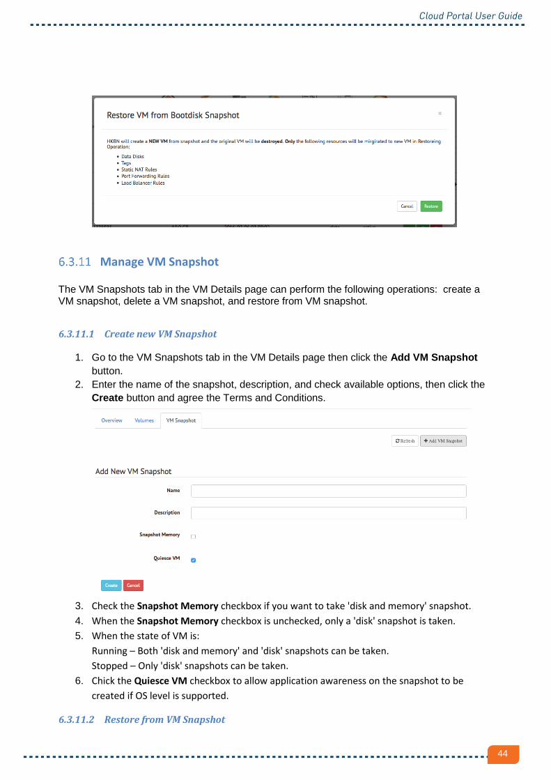
Manage VM Snapshot The VM Snapshots tab in the VM Details page can perform the following operations: create a VM snapshot, delete a VM snapshot, and restore from VM snapshot.
6.3.11.1 Create new VM Snapshot
1. Go to the VM Snapshots tab in the VM Details page then click the Add VM Snapshot
button.
2. Enter the name of the snapshot, description, and check available options, then click the
Create button and agree the Terms and Conditions.
3. Check the Snapshot Memory checkbox if you want to take 'disk and memory' snapshot.
4. When the Snapshot Memory checkbox is unchecked, only a 'disk' snapshot is taken.
5. When the state of VM is:
Running – Both 'disk and memory' and 'disk' snapshots can be taken.
Stopped – Only 'disk' snapshots can be taken.
6. Chick the Quiesce VM checkbox to allow application awareness on the snapshot to be
created if OS level is supported.
6.3.11.2 Restore from VM Snapshot

45
Click the Restore VM button in the VM Snapshots tab to restore the VM.
6.3.11.3 Delete VM Snapshot
Click the red trash can button in VM Snapshots tab to delete the VM snapshot.
Attach / Detach ISO
1. Click the blue Attach button in the VM Details page.
2. Select an ISO File then click the green Attach button.
3. Click the red Detach button to detach the ISO.

46

47
7 Resource The Resource Menu contains functions for managing integrated resource pools.
7.1 Resource Pools
Click the Resource icon in the top menu to show a list of integrated resource pools. In this example, there is one resource pool - named HKBNL955R. For each resource pool, users can manage the following functions:
● Regions
● Usage & Limit
● Networking
● Offering
● Images
● Snapshots
● Volumes
● ISOs
7.2 Regions
A resource pool can have multiple zones, one zone is defined by default and multiple zones are not supported.
7.3 Usage & Limits
Resource limit is assigned on a per tenant basis. This is to prevent individual tenant from consuming too much platform resources and causing performance issues. The following chart shows assigned vs. consumed resources.

48
7.4 Networking
The Networking tab allows users to manage networks in a resource pool.
User can perform the following network operations:
● create / delete / manage flat network
● create / delete / manage VPC
● create / delete VPN customer gateways
● acquire / release public IP etc.
VPC Network The Virtual Private Cloud (VPC) is a private, isolated part of cloud platform. A VPC can have its own virtual network topology that resembles a traditional physical network. You can launch VMs in the virtual network that can have private addresses in the range of your choice. You can define network tiers within your VPC network range, which enables you to group similar kinds of instances based on IP address range. Users can manage VPC networks by going to the Networking tab > VPC tab on the Resource page.
1. Click the Resource icon in the Top Nav menu.
2. Click the Networking tab then click the VPC tab.

49
Users can manage the following VPC functions:
● create / delete VPC
● update VPC name
● restart VPC
● add site-to-site VPN
● add / remove ACL lists
● create / delete subnet
● acquire new IP for the VPC subnet.
Note: VPC is pre-provisioned by HKBN and customers are highly recommended NOT to delete and/or create VPC via cloud portal. Users can also see all subnets in the Networks tab:
7.4.1.1 Edit and Restart VPC To edit or restart a VPC:
1. Go to the VPC tab.
2. Click the VPC name or Edit button to view the details of the VPC.
3. Click the Overview tab.
4. Change the VPC Name and/or Display Name then click the Update Network button to
update the VPC.
5. To restart the VPC, follow the above step 1 and 2 then click the blue Restart VPC button.

50
7.4.1.2 Subnet
7.4.1.2.1 Create Subnet (Tier) To create a VPC subnet:
1. Go to the VPC tab.
2. Click the VPC name or Edit button to view the details of the VPC.
3. Click the Subnets tab.
4. Click the Add Subnet button.
5. Fill in the Create New Subnet form.

51
Name - name of this subnet. Display Text - display name of this subnet. Network Offering - select one of the offerings. Gateway - must be within the CIDR of VPC. Netmask - netmask of this subnet.
ACL List - select one of the existing ACL lists or select Create a new ACL list for the
system to create a new one for you.
6. Click the red Create button.
7. Agree the Terms and Conditions.
The Notification Center will show the progress of the subnet creation. The page will be auto-refreshed after the new subnet is created.
7.4.1.2.2 Edit Subnet Users can edit the subnet in the subnet details page. There are 2 ways to go to the subnet details page:
1. Click the subnet Name or Edit button in Networks tab.
2. Go to the Subnet tab in VPC details page and click the Edit button.
In the subnet details page, users can update the subnet’s Name and/or Display Name. Once completed, click the Update Network button.

52
7.4.1.2.3 Subnet ACL Rules To edit the ACL Rules of a subnet:
1. Go to the VPC tab.
2. Click the VPC name or Edit button to view the details of the VPC.
3. Click the Subnets tab and then click the Edit button of the subnet.
4. Click the ACL Rules tab.

53
Users can add or delete ACL rules. Users can also reorder the ACL rules by dragging and dropping, and then click the Update Order button. By default, the “Egress allows all” rules was added during creation.
7.4.1.2.4 Delete Subnet
1. Go to the VPC tab.
2. Click the VPC name or Edit button to view the details of the VPC.
3. Click the Subnets tab.
4. Click the red Delete Subnet button.
Please note that users cannot delete a subnet with any associated VM.
7.4.1.3 Acquire IP There are 2 ways to acquire New IP to a VM.
1. Go to the VM details page and click the Acquire Public IP for Static NAT button.

54
2. Go to the Network details page by clicking the Network Name of Edit button in
Networks tab.
1. Click the Public IPs tab in the Network details page.
2. Click the Acquire New IP button.
3. Agree the Terms and Conditions.
4. The new IP should show up in the same page after it has been created. Click the
IP or Edit button to go into the IP details page.

55
5. Click the Enable Static NAT button in the IP details page.
6. Select one of the VMs from the drop down list then click the red Enable Static
NAT button.
Please note that if the IP has any Port Forwarding or Load Balancer rules then this IP cannot enable Static NAT. There are a few ways to release an IP.
1. Click the Release IP button in the VM details page.
2. Click the Release IP button in the Network > Public IPs tab.
3. Click the Release IP button in the Public IPs tab in Network details page.
Please note that the Source NAT IP cannot be released.
7.4.1.4 VPC site-to-site VPN
Local Office
192.168.0.0/24
Remote SiteRemote SiteVPCVPC
Web Tier
10.0.1.0/24
10.0.2.0/24
10.0.3.0/24
Application Tier
Database Tier
10.0.0.0/16 FirewallFirewall
Site-to-site VPN is supported by VPC, which enables VPN connection between VPCs and hardware-based VPN devices (e.g. firewall) at remote site such as your local office, datacenter or co-location facility network. A VPN customer gateway is needed for creating VPC site-to-site VPNs.
7.4.1.4.1 VPC Customer Gateway To view all of the VPN customer gateways, click the VPN Customer Gateways tab.

56
Users can add, delete, or edit a VPN customer gateway. To add a new VPN customer gateway:
1. Click the Add VPN Customer Gateway tab.
2. Fill in the following form.
3. Click Create button.
To edit the VPN customer gateway:
1. Go to the VPN Customer Gateways tab.
2. Click the Name or Edit button.
3. Update the value and click the Update Gateway button.
To delete the VPN customer gateway:
1. Go to the VPN Customer Gateways tab.
2. Click the red Delete button.
7.4.1.4.2 Setting up VPC site-to-site VPN There must be at least one VPN customer gateway created in order to create a site-to-site VPN. To add a new site-to-site VPN:
1. Go to the VPC tab.
2. Click the VPC Name or Edit button to the VPC details page.
3. Click the Site-to-site VPN tab.

57
4. Select the Customer Gateway and click the Add button.
5. Then users should see the following:
6. Click the Toggle Details button to Reset or Refresh the connection.
7. Click the red Delete VPN connection button to delete it.
7.4.1.4.3 Example for configuring Site-to-Site VPN connection at customer’s IT infrastructure
Cisco ASA, Juniper SRX and Juniper Netscreen are popular firewalls to terminate site-to-site VPN connection for enterprises. According to the parameter inside the captured screen in previous example, below are the suggested site-to-site VPN configuration of Cisco ASA, Juniper SRX and Juniper Netscreen at customer site. Note that if the equipment or configuration is different from below examples, greater effort and longer time may be needed for the planning and coordination of the setup.

58
7.4.1.4.4 Cisco ASA Configuration
conf t crypto ikev1 policy 1 authentication pre-share encryption aes-256 hash sha group 5 lifetime 86400 crypto ikev1 enable outside crypto ikev2 policy 1 encryption aes-256 prf sha lifetime seconds 3600 crypto ikev2 enable outside crypto ipsec ikev1 transform-set V1-ESP-AES256-SHA esp-aes-256 esp-sha-hmac crypto ipsec ikev2 ipsec-proposal V2-AES256-SHA1 protocol esp encryption aes-256 protocol esp integrity sha-1 exit crypto ipsec security-association lifetime seconds 3600 object-group network CustomerLAN network-object 192.168.100.0 255.255.255.0 object-group network VPC_Network network-object 10.4.2.0 255.255.255.0 exit access-list ACL_VPN_VPC extended permit ip object-group CustomerLAN object-group VPC_Network tunnel-group 1.1.1.1 type ipsec-l2l tunnel-group 1.1.1.1 ipsec-attributes ikev1 pre-shared-key SecretPassword exit crypto map map_outside 1 match address ACL_VPN_VPC crypto map map_outside 1 set pfs group5 crypto map map_outside 1 set peer 1.1.1.1 crypto map map_outside 1 set ikev1 transform-set V1-ESP-AES256-SHA crypto map map_outside 1 set ikev2 ipsec-proposal V2-AES256-SHA1 crypto map map_outside interface outside nat (inside,outside) source static CustomerLAN CustomerLAN destination static VPC_Network VPC_Network no-proxy-arp end write

59
7.4.1.4.5 Juniper SRX Configuration
Phase– I (IKE VPN) configurations
set security ike proposal Pre-G5-AES256-SHA1 authentication-method pre-shared-keys
set security ike proposal Pre-G5-AES256-SHA1 dh-group group5
set security ike proposal Pre-G5-AES256-SHA1 authentication-algorithm sha1
set security ike proposal Pre-G5-AES256-SHA1 encryption-algorithm aes-256-cbc
set security ike proposal Pre-G5-AES256-SHA1 lifetime-seconds 86400
set security ike policy VPC-IKE-Policy mode main
set security ike policy VPC-IKE-Policy proposals Pre-G5-AES256-SHA1
set security ike policy VPC-IKE-Policy pre-shared-key ascii-text SecretPassword
set security ike gateway VPC-GW ike-policy VPC-IKE-Policy
set security ike gateway VPC-GW address 1.1.1.1
set security ike gateway VPC-GW external-interface reth0
set security ike gateway VPC-GW general-ikeid
Phase-II (IPSEC VPN) configurations
set security ipsec proposal ESP-G5-AES256-SHA1 protocol esp
set security ipsec proposal ESP-G5-AES256-SHA1 authentication-algorithm hmac-sha1-96
set security ipsec proposal ESP-G5-AES256-SHA1 encryption-algorithm aes-256-cbc
set security ipsec proposal ESP-G5-AES256-SHA1 lifetime-seconds 3600
set security ipsec policy VPC-IPSec-Policy perfect-forward-secrecy keys group5
set security ipsec policy VPC-IPSec-Policy proposals ESP-G5-AES256-SHA1
set security ipsec vpn VPC-VPN ike gateway VPC-GW
set security ipsec vpn VPC-VPN ike ipsec-policy VPC-IPSec-Policy
set security ipsec vpn VPC-VPN establish-tunnels immediately
To access protected resources, there should be traffic passing policy from untrust zone to
trust zone where the protected resource is located, is configured as follows.
set security zones security-zone trust address-book address CustomerLAN 192.168.100.0/24
set security zones security-zone untrust address-book address VPC_Network 10.4.2.0/24
set security policies from-zone untrust to-zone trust policy VPC-CustomerSite match source-
address VPC_Network
set security policies from-zone untrust to-zone trust policy VPC-CustomerSite match
destination-address CustomerLAN
set security policies from-zone untrust to-zone trust policy VPC-CustomerSite match
application any
set security policies from-zone untrust to-zone trust policy VPC-CustomerSite then permit
tunnel ipsec-vpn VPC-VPN
set security policies from-zone untrust to-zone trust policy VPC-CustomerSite then permit
tunnel pair-policy CustomerSite-VPC
Interface connected to Internet, depend on the customer device configuration.
Zone names depended on the customer device

60
set security policies from-zone untrust to-zone trust policy VPC-CustomerSite then log
session-init
set security policies from-zone trust to-zone untrust policy CustomerSite-VPC match source-
address CustomerLAN
set security policies from-zone trust to-zone untrust policy CustomerSite-VPC match
destination-address VPC_Network
set security policies from-zone trust to-zone untrust policy CustomerSite-VPC match
application any
set security policies from-zone trust to-zone untrust policy CustomerSite-VPC then permit
tunnel ipsec-vpn VPC-VPN
set security policies from-zone trust to-zone untrust policy CustomerSite-VPC then permit
tunnel pair-policy VPC-CustomerSite
set security policies from-zone trust to-zone untrust policy CustomerSite-VPC then log
session-init
insert security policies from-zone trust to-zone untrust policy CustomerSite-VPC before policy
AllowAllOutgoing
Configure NAT OFF for VPN traffic
set security nat source rule-set trust-to-untrust from zone trust
set security nat source rule-set trust-to-untrust to zone untrust
set security nat source rule-set trust-to-untrust rule VPC-NAT-OFF match source-address
192.168.100.0/24
set security nat source rule-set trust-to-untrust rule VPC-NAT-OFF match destination-address
10.4.2.0/24
set security nat source rule-set trust-to-untrust rule VPC-NAT-OFF then source-nat off
insert security nat source rule-set trust-to-untrust rule VPC-NAT-OFF before rule source-nat-
rule
Depend on the customer device, it should be the last policy.
Rule name depended on the customer device, it should be the last rule.

61
7.4.1.4.6 Juniper Netscreen Configuration set ike p1-proposal "Pre-G5-AES256-SHA1" preshare group5 esp aes256 sha-1 second 86400 set ike p2-proposal "ESP-G5-AES256-SHA1" group5 esp aes256 sha-1 second 3600 set ike gateway GW_VPC address 1.1.1.1 main outgoing-interface ethernet1 preshare SecretPassword proposal Pre-G5-AES256-SHA1 set ike gateway GW_VPC nat-traversal set vpn VPC gateway GW_VPC tunnel proposal ESP-G5-AES256-SHA1 set address Untrust VPC_Network 10.4.2.0/24 set address Trust CustomerLAN 192.168.100.0/24 set policy top name VPN_To_VPC from Trust to Untrust CustomerLAN VPC_Network any tunnel vpn VPC set policy top name VPN_From_VPC from Untrust to Trust VPC_Network CustomerLAN any tunnel vpn VPC save
Flat Network In case when client-to-server VPN is needed (L2TP/IPSEC), customer could create a Flat Network via the cloud portal.
7.4.2.1 Create / Delete Flat Network To create a flat network:
1. Click the Networks tab.
2. Click the Add Flat Network button.
3. Fill in the Create Flat Network form:
Name - flat network name. Display Text - flat network display name. Zone - the name of the zone this network applies to. Network Offering - select one of the network offerings.
Interface name depended on the customer device.

62
Gateway - this flat network gateway. E.g. 192.168.1.1 Netmask - this flat network netmask. E.g. 255.255.255.0
4. Click Create button.
5. Agree the Terms and Conditions.
The Notification Center will show the progress of the network’s creation. The page will be auto-refreshed after the new flat network is created. To delete a flat network:
1. Click the Resource icon from the Top Nav menu.
2. Click the Networking tab in Resource Pool page.
3. Click the Networks tab.
4. Find the network that you want to delete, then click Delete button.
Please note that network cannot be deleted if the flat network is associated with any VM. The Networks tab shows how many VMs are associated with this flat network. Mouse over Associated VMs to show the correspondent VM names.
7.4.2.2 Add / Remote Egree Rule To add Egress rule in a flat network:
1. Click the Resource icon from the Top Nav menu.
2. Click the Networking tab in Resource Pool page.
3. Click the Networks tab.
4. Find the flat network then click the Edit button or click on the Name of the network to
edit the details of this flat network.
5. Click the Egress Rules tab.

63
6. Enter the source cidr, select protocol, start port / ICMP type and end port / ICMP code
then click the Add Rule button.
To remove an Egress rule. 1. Go back to your flat network egress rules tab.
2. Find the egress that you want to remove.
3. Click the red Delete Egress Rule button.
7.4.2.3 Acquire New / Release IP Users can acquire new IPs from the VM details page or you can go to the Public IP tab in the Networks details page and click the Acquire New IP button. Then click the Enable Static NAT button in the IP details page. The same steps can be applied to acquiring new IPs for a flat network. Please see the Acquire New / Release IP section under VPC Network for more details.

64
7.4.2.4 Configure remote access VPN using L2TP/IPsec Enabled Client
Remote NetworkRemote NetworkBasic NetworkBasic Network
192.168.1.0/24
Instance Network
Client / ServerClient / Server
Available in Flat Network, enable external host access to cloud virtual servers securely using L2TP/IPSec client. To add client to site VPN:
Click the Resource icon in the Top Nav menu.
Click Networking tab in the Resource Pool page.
Click Public IPs tab.
Click and select the Public IP for the flat network to enable client to access site VPN
Click VPN and + Enable Remote Access VPN
Input the Username and Password for remote access client.

65
7.4.2.5 External Client setup for Remote Access VPN using L2TP/IPsec
For the external host, set up a new connection for VPN client.
For the Internet address, input your VPN Gateway IP address.

66
Input your VPN user account login details. Click Connect to continue.
Click Skip to continue.

67
Right click My VPN Connection icon.

68
Select Layer 2 Tunneling Protocol with IPsec (L2TP/IPsec) as the Type of VPN. Click Advanced setting button to continue.
Input the IPsec Preshared Key information to the below field. Click OK button to continue.

69
Launch the VPN connection and input the user account login details.
Upon a successful login status, the external host should be able to access the virtual servers securely over IPsec encrypted connection.

70
Public IP
To view all Public IP addresses of all networks, VPCs and subnets:
Click the Resource icon in the Top Nav menu.
Click Networking tab in Resource Pool page.
Click Public IPs tab.
It shows all public IPs in this page. Only Static NAT IP can be released. Click the IP or Edit button to go to the IP details page. Click the Network / VPC link to go to either the Network or VPC details page. Click the Associated VM to go to the VM details page.
7.4.3.1 Port Forwarding To manage port forwarding of an IP:
Go to the IP details page.
Click the Portforwarding tab.
You can add a new port forwarding rule by entering the private start / end ports, public start / end ports, select protocol and VM.

71
Click the red Delete Portforwarding Rule button to remove any rule. Please note that the Port Forwarding is disabled when the IP is enabled Static NAT.
7.4.3.2 Load Balancer To manage load balancer rules of an IP:
Go to the IP details page.
Click the Load Balancer tab.
Enter the rule name, public / private port and select one of the algorithms then click Add button.
After the rule is created, click the Toggle Details button to access the VM and Stickiness Policy.

72
Stickiness Policy None: Do not use stickiness policy SourceBased: The source IP address is used to identify the user and locate user’s stored data AppCookie: Cookies are used. The cookie generated by the application is included in request and response URLs to create persistence LbCookie: Cookies are used. The cookie generated by the Load Balancer is included in request and response URLs to create persistence
Click the red Delete Loadbalancer Rule button to remove any rule. Please note that the Load Balancer is disabled when the IP is enabled with Static NAT.

73
7.4.3.3 VPN To enable VPN:
Go to the IP details page.
Click the VPN tab.
Click the Enable Remote Access VPN button.
After the VPN remote access is enabled, you should see the following:
Add the username and password to access the VPN.
7.5 Templates
Users can create VM easily by using VM templates, or import a VM by uploading VM template in OVA format.
Upload Templates To upload a template:
Click the Templates tab in Resource Pool page.

74
Click the Upload button.
Please enter the following information in the Upload Your Own Cloud Template form:
a. Display Text and Name - the name of this template. b. URL - the system will download the file from this URL. Eg. http://www.mycompany.com/download/centos6_4-image.ova c. Zone - choose one of the zones where you want the template to be available. d. Hypervisor - select one of the supported hypervisors. (Default: VMware) e. Format - the format of the template upload file. (Default: OVA) f. Root disk controller - this is an optional field for VMWare hypervisor. Specify the default disk controller for root volume. (Default: SCSI) g. NIC adapter type - this is an optional field for VMWare hypervisor. Specify the default network device type for system VMs. (Default: Vmxnet3) h. Keyboard type - this is an optional field for VMWare hypervisor. Select one of the keyboard device types. (Default: US Keyboard) i. OS Type - this helps CloudStack and the hypervisor perform certain operations and make assumptions that improve the performance of the guest. j. Extractable - check this if the template is available for extraction. k. Password Enable - check this if the template has the CloudStack password change script installed. l. Dynamically Scalable - check this if template contains XS/VMWare tools in order to support dynamic scaling of VM cpu/memory. m. HVM - check this if the template requires HVM.
Click the Create button to create the template.
Agree to the Terms and Conditions.
You should see your uploaded template in the template list when the template is created successfully.
Download Templates
Users can download templates that have been updated to the system by the following steps:
Click the Templates tab in the Resource Pool page.
Select Download from the Action button .

75
Delete Templates
Users can delete templates that have been uploaded to the system by the following steps:
Click the Templates tab in Resource Pool page.
Select Delete from the Action button .
7.6 Volumes
Users can manage disk volumes by clicking on the Volumes tab. The following are key functions:
1. Locations Users can click on the Locations to select a location to display a list of volumes 2. Name Search Users can type a name to be searched
3. Upload
Users can upload a volume by providing the following info and click Create:
Name: URL: location to download the disk volume Zone: the zone to store the volume Format: disk format
Disk Offering: for environment with more than one disk offering, specify the offering. Checksum: check for consistency

76
4. Refresh
Users can redisplay the list of volumes by clicking on the Refresh button 5. Action
Users can download, attach or delete the volumes.
Download: a new browser window will be opened to start downloading Attach: select a VM from the dropdown list to attach the volume
Delete: delete the volume
7.7 ISOs
Users can manage ISO images by clicking on the ISO tab. The following are key functions:
1. Locations Users can click on the Locations to select a location to display a list of volumes 2. Name Search Users can type a name to be searched
3. Upload

77
Users can upload an ISO image by providing the following info. and click Create:
Name: Description: URL: location to download the ISO image OS Type: select an OS format
Zone: the zone to store the ISO image Bootable: check if the ISO image is bootable
Extractable: check if the ISO image is extractable
4. Refresh Users can redisplay the list of volumes by clicking on the Refresh button

78
8 Settings
The Settings Menu allows users to configure tenant and user level preferences.
8.1 My User Profile
The My User Profile section consists of 3 functions: ● General
○ Users can set and update contact information and change password.
● Preferences
○ Users can set time zone preferences.
● Access History
○ Detailed access records are kept.

79
8.2 My Account
The My Account section allows users to enter and update tenant level information. It consists of My Account, API Key and Branding.
My Account - General Users can enter and update contact information.
My Account - Preferences The Preferences tab on the upper right side brings up the account Preferences page, with editable parameters for Monitoring and VM Lifetime policy.

80
8.2.2.1 Monitoring Enable / Disable email notification. Add email address(es) for this notification.
1. Go to the My Account page in Settings tab.
2. Click the Preferences tab.
3. Click the Monitoring text label.
4. Click the Email Notification check box if you want to receive email notifications.
5. Enter Email Addresses for those who will receive notification emails.
6. Click the Save button.
8.2.2.2 VM Lifetime Policy Set the default value for the lifetime of the VM.
1. Go to the My Account page in Customer Portal.
2. Click the Preferences tab.
3. Click the VM Lifetime Policy text label.
4. Select the Default value of VM lifetime in the drop down menu.
5. Click the Save button.
This will be the default value populated in Lifetime field in the Launch VM page.

81
8.3 Users
HKBN Cloud platform is a multi-tenant and multi-user system with granular security controls. Administrators can add, modify and delete users from the tenant account. Each user will have his/her own login/password for accessing the HKBN Cloud Portal.
Add New User Users with Admin roles can add user accounts on a tenant:
1. On the Users Management interface, click the Add User button.
2. Fill in the New User form by entering the Login Name, First Name, Last Name, Email and
Password

82
3. Select the user’s Role.
Guest – This group allows a user to view server, to access remote console and different types of resources including VM, disks, network, etc. Power Users – This group allows to access most administration functions. A power user is able to view, create, delete, and manage all types of resources within the tenant. Admin – This group allows to access most administration functions. In addition, an Admin account can also access to user management page to add, delete or modify user.
4. Click the Save button.
5. The newly added users will appear in the Users Management interface.
8.3.1.1 Modify User Properties Users with Admin roles can edit user properties:
1. In the Users Management interface, click the Edit button in the Actions column of the user’s
name.
2. You will be redirected to the Edit User page. Modify the necessary fields.
3. Click the Save button.
8.3.1.2 Delete User Users with Admin roles can delete user accounts on a tenant:
1. In the Users Management interface, mouse over to the Actions column of the user’s name.
2. Click the Drop User button.
3. A dialog box will prompt the administrator to delete the user.
4. Click the OK button.

83
Note: This action will permanently remove user records and settings in the system.
8.3.1.3 Add User to Aproval_flow
Users with Admin roles can assign users to approval chains:
1. In the Users Management interface, click the Edit button in the Actions column of the user’s
name.
2. You will be redirected to the Edit User page. Scroll down to Approval section.
3. Select the Default_Approval_Chain and click the Save button.
Note: A simple Default Approval Chain is pre-configured and available for selection, which request approval by Admin account for every work order (e.g. VM provisioning / termination). Approval chain can be fine-tuned by HKBN to meet customer’s need, please contact your account manager for details.

84
9 Monitoring The Monitoring Menu contains functions for managing integrated cloud monitoring.
9.1 Login the Monitoring tool
1. Enter Login Name and Password (Same as portal), then click Login.
2. After a successful login, you can view information in dashboard including the followings:-
Overview your managing devices
Devices current status

85
9.2 View your device information & detail
Launch more status & resource usage
1. Click device you want to check
2. Device Dashboard
Shown device current status (Last up time, Last down time, Uptime percent, Downtime percent & Coverage) & resource usage (CPU, Memory, Disk & network etc).
View the performance data by chart
1. Select the time period in device dashboard
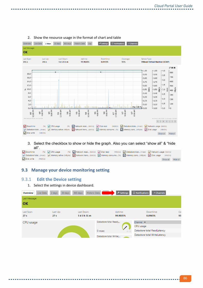
86
2. Show the resource usage in the format of chart and table
3. Select the checkbox to show or hide the graph. Also you can select “show all” & “hide all”.
9.3 Manage your device monitoring setting
Edit the Device setting 1. Select the settings in device dashboard.

87
2. Fill in and select your options in the Setting page for device
BASIC SENSOR SETTINGS - Sensor Name : Enter a meaningful name to identify the sensor. By default, system shows this name in the
device tree, in alarms, logs, notifications, reports, maps, libraries, and tickets. (No recommend
change it)
- Parent Tag : Don’t change
- Tag : Don’t change
- Priority : Define the priority status of this object. System sorts this object in lists according to its priority,
and the resource will be resized by priority. Below is an example for priority 3 & 4.
VMWARE VIRTUAL MACHINE SETTINGS
Size for Priority 4 Size for Priority 3

88
- Handling of "Powered Off" VM : Ignore "powered off" state (default) - In default setting, the sensor will
not report a 'down' status when a virtual machine is powered off. If the
powered off status is ignored, the sensor will report 0 value instead.
Alarm when VM is "powered off" – The system will show the error when
VM is powered off, even the manual is power off.
SENSOR DISPLAY
- Primary Channel : Choose the resource you want to classify as primary. The newest value of the primary
resource will always be displayed for this sensor. The primary resource can also be used to
trigger notifications.
- Chart Type : Select how to display the graph. If you choose 'Show resources independently', every resource
is displayed in a individual graph. Choose “Stack resources on top of each other” to create a
multi- resource graph.
Recommend to use “Show channels independently (default)”
SCANNING INTERVAL
- Scanning Interval : Time between 2 scans of resource data
- When a Sensor Reports an Error : When a sensor reports an error, system can try reaching the corresponding
device again with the next scanning interval before the sensor is shown as
'down'. This can avoid false alarms if your device has temporary issues only.
Suspend device monitoring
1. Unclick the checkbox under “Schedules, Dependencies, and Maintenance Window”
- Schedule : Set “None”
- Maintenance Window : Not set (monitor continuously) – No set to Maintenance mode.
- SET UP A ONE-TIME MAINTENANCE WINDOW – Select this option will show the
fields “Maintenance Begins At” & “Maintenance Ends At”. Enter the time period you
want to ignore.
- Dependency Type : Use default setting, no need to set.
- Delay (Seconds) : Enter a value (in seconds). Resuming of monitoring for this object will be additionally
delayed after the master object for this dependency is 'Up' again. This is helpful for

89
devices with sensors that need some time to resume after the restart of a device, while
usually the dependency sensor (e.g. Ping) is already 'Up'. A delay can avoid false
alarms.
9.4 Review or download historic data
1. Select the “Historic Data” in device dashboard.

90
2. Review or download historic data setting option
- Start : Enter your preferred start time.
- End : Enter your preferred end time.
- Quick Range : You can select the range by “quick range” and will auto fill in “Start” & “End”.
- Average Interval : Select an interval for averaging. For time spans more than 40 days, the minimum interval is 60
minutes. If set below, it will be increased automatically. If you set a value less than the
minimum Scanning Interval (This setting set in “4.1 Edit the Device setting”). Some data may be
lost in the report.
- Channels : Select the resources you want to include.
- File Format : HTML web page for viewing only. And XML & CSV files for downloading only
- Percentile Results : ‘On’ displays a percentile calculation for each resource in an overview table with
averages/sums for each resource.

91
3. If you select File Format to HTML web page, the system will take a time to generate the data
4. Sample for the HTML web page format report (Chart)
5. Sample for the HTML web page format report (Table)
9.5 Add report (Support html format only)

92
Create the report
1. Select “Reports” > “Add report” in toolbar
2. Add report setting option. please fill & select your option
- Report Name : Enter a report name.
- Tags : Enter a list of tags (not case sensitive) for filtering purposes.
- Template : Choose a report template from the list of available templates. There are templates that offer
optional data tables besides the graphs. You can also specify the graph/calculation intervals by
selecting a template.
- Timezone : Timezone setting for all dates regarding this report. This includes schedule dates, report time
span, and dates in tables/graphs.
- Paper Size : Specify the paper size for which the report will be formatted. Choose between the DIN A4, the
US legal paper and the US letter paper format.

93
- Add Sensors by Tag : Add “esxservervmsensor” if you want all device include in report. For the setup
specify device, don’t select any tag and will show you in step 6.1.1.
- Filter Sensors by Tag : No need to set
- Report Schedule : Don’t select any option
- Reported Period : Specify which period is to be reported. Please choose between daily, weekly, monthly,
quarterly or yearly reports. Examples: Current is 'today' for daily reports, 'current
month' for monthly reports. Previous means 'yesterday' for daily reports, 'last month'
for monthly reports.
- Report Period Type : Specify which period is to be reported. Please choose between daily, weekly, monthly,
quarterly or yearly reports. Examples: Current is 'today' for daily reports, 'current
month' for monthly reports. Previous means 'yesterday' for daily reports, 'last month'
for monthly reports.
- Week Period : Define when the week will start and end.
- Report Only for Specific Hours-of-Day (Schedule) : None (no need to set)
- Percentile Results : 'Show percentiles' displays a percentile calculation for each resource in an overview table with
averages/sums for each resource.

94
- Introduction : This introductory text will be shown on the report's first page.
- Footer Comments : These comments will be shown at the end of a report.
3. Complete the above setting, click the Continue button
4. The Select Sensors Manually page is shown. This page is manual setup and device data is
included in the report. If you don’t want to set it, select the Run Now tag and click the Run
Report button. If you want to set it, go to “6.1.1 select sensors manually”
5. The system will take a time to generate the report

95
6. Sample for the report (HTML format)

96
Select Sensors Manually
1. If you want to specify the device, you can select the device and drag & drop to the Objects tag.
(Hints are shown in the system)
2. After the device is added, you can select the checkboxes to include the related resource
information in the report.

97
9.6 Manage your saved report
View and run your saved report
1. When the report is generated, system will save your report setting. You can find the saved report in toolbar “report” > “All”
2. You can find what report created.
3. If you want to view the report again, click the report name.
4. Click the Run Report button
5. The system will take time to generate the report

98
6. Sample for the report (HTML format)
Delete your report
1. Go to report baseboard, click “Reports” > “All” in toolbar.
2. You can find all the reports generated.

99
3. Click the Delete button
4. Note the warning message & click the Delete Object button.
Edit your report
1. Go to report baseboard, click “Reports” > “All” in toolbar.
2. You can find all the reports generated.
3. Click the Edit button
4. The report setting is shown and you can refer the setup in “9.5.1 Create the report”

100
Clone your report
1. Go to report baseboard, click “Reports” > “All” in toolbar.
2. You can find all the reports generated.
3. Click the Clone button

101
4. The report has been cloned and named as “Clone of (source report name)”. You can edit the
report by clicking the Edit button.
9.7 VM resource warning /error status & email notification
Setup the warning /error status
You can set the resource usage alert level (For example, when CPU usage is over 70%, you can define it as warning status). You can coordinate the email notification (please go to “9.8”) to alert your VM resource utilization.
1. Click device you want to setup.
2. Select the object (e.g. cpu, memory, disk.) and click the Edit channel setting button.

102
3. Select Enable limits.
- Upper Error Limit (%) : Values above this value will set the sensor state to 'Down'.
- Upper Warning Limit (%) : Values above this value will set the sensor state to 'Warning'.
- Lower Warning Limit (%) : Values below this value will set the sensor state to 'Warning'.
- Lower Error Limit (%) : Values below this value will set the sensor state to 'Down'.
- Error Limit Message : This message is added to the error status.
- Warning Limit Message : This message is added to the warning status.
4. After the setting is applied, the CPU usage status is updated. (Yellow for warning, Red for Error)

103
Setup email notification
1. Go to the below URL to set up email address
https://monitoring.hds-cloudconnect.com/myaccount.htm?tabid=2
2. Input your email address in the Notification Name field and click the SEND EMAIL button
3. Input your email address to highlighted field

104
4. Go to device dashboard and select device you want to set up.
5. Click the Notifications tag

105
6. Click the Add State Trigger button
7. Change the settings & email address.