verigy v93000 service training module 4: low level diagnostic
TRANSCRIPT

Verigy V93000Service Training
Module 4:Low Level Diagnostic
04 - Low Level DiagnosticPage 2
Verigy Restricted
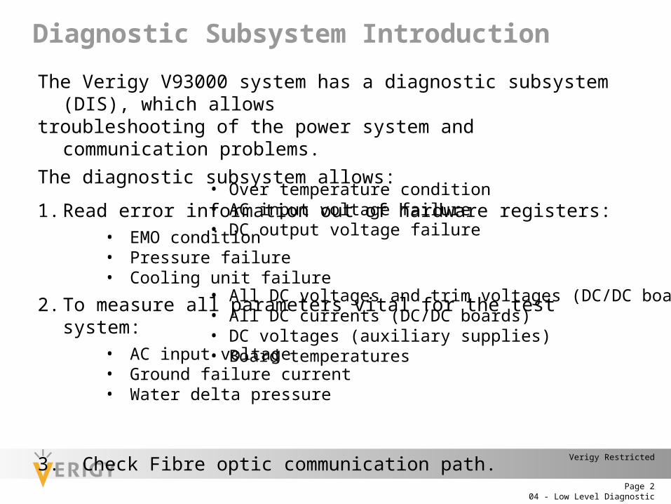
Diagnostic Subsystem Introduction
The Verigy V93000 system has a diagnostic subsystem (DIS), which allowstroubleshooting of the power system and communication problems.The diagnostic subsystem allows:
1. Read error information out of hardware registers:• EMO condition• Pressure failure• Cooling unit failure
2. To measure all parameters vital for the test system:• AC input voltage• Ground failure current• Water delta pressure
3. Check Fibre optic communication path.
• Over temperature condition• AC input voltage failure• DC output voltage failure
• All DC voltages and trim voltages (DC/DC boards)• All DC currents (DC/DC boards)• DC voltages (auxiliary supplies)• Board temperatures
04 - Low Level DiagnosticPage 3
Verigy Restricted
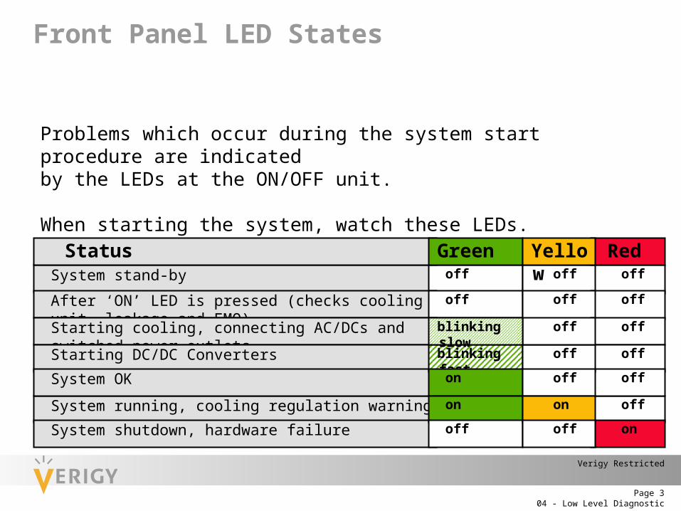
System stand-by offoff off
After ‘ON’ LED is pressed (checks cooling unit, leakage and EMO) offoff off
Front Panel LED States
Problems which occur during the system start procedure are indicatedby the LEDs at the ON/OFF unit.
When starting the system, watch these LEDs.
Status
Starting cooling, connecting AC/DCs and switched power outlets
Starting DC/DC Converters
System running, cooling regulation warning
System shutdown, hardware failure
System OK
Green Red
off
blinking fast
off
off
off
off
on
on off
Yellow
on
off
on
off
offblinking slow
04 - Low Level DiagnosticPage 4
Verigy Restricted
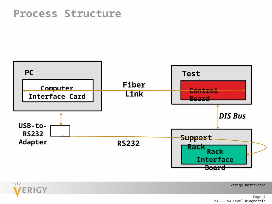
Process Structure
Fiber Link
PC Test Head
RS232Rack Interface
Board
Control Board
DIS Bus
Computer Interface Card
Support Rack
USB-to-RS232
Adapter
04 - Low Level DiagnosticPage 5
Verigy Restricted
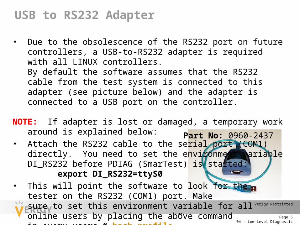
• Due to the obsolescence of the RS232 port on future controllers, a USB-to-RS232 adapter is required with all LINUX controllers.By default the software assumes that the RS232 cable from the test system is connected to this adapter (see picture below) and the adapter is connected to a USB port on the controller.
NOTE: If adapter is lost or damaged, a temporary work around is explained below:• Attach the RS232 cable to the serial port (COM1) directly. You need to set the
environment variable DI_RS232 before PDIAG (SmarTest) is started: export DI_RS232=ttyS0
• This will point the software to look for the tester on the RS232 (COM1) port. Make sure to set this environment variable for allonline users by placing the above command in every users “.bash_profile”
Part No: 0960-2437
USB to RS232 Adapter
04 - Low Level DiagnosticPage 6
Verigy Restricted
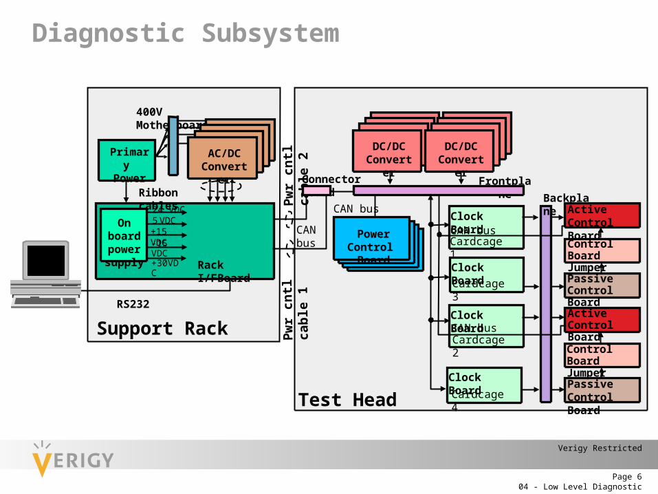
Diagnostic Subsystem
Frontplane
CAN bus
Power Control Board
Primary Power
400V Motherboard
Rack I/FBoard
Ribbon cables
Support Rack
DC/DCConverter
DC/DCConverter
Connector board
Clock Board
Clock Board
Clock Board
Clock Board
Cardcage 1
Cardcage 2
Cardcage 3
Cardcage 4
CAN bus
CAN bus
Test Head
Backplane
RS232
On board power supply
24 VDC5 VDC+15 VDC-15 VDC+30VDC
Pwr c
ntl c
able
2Pw
r cnt
l cab
le 1
CAN bus
Active Control Board
Passive Control Board
Control BoardJumper
Active Control Board
Passive Control Board
Control BoardJumper
AC/DCConverter
04 - Low Level DiagnosticPage 7
Verigy Restricted
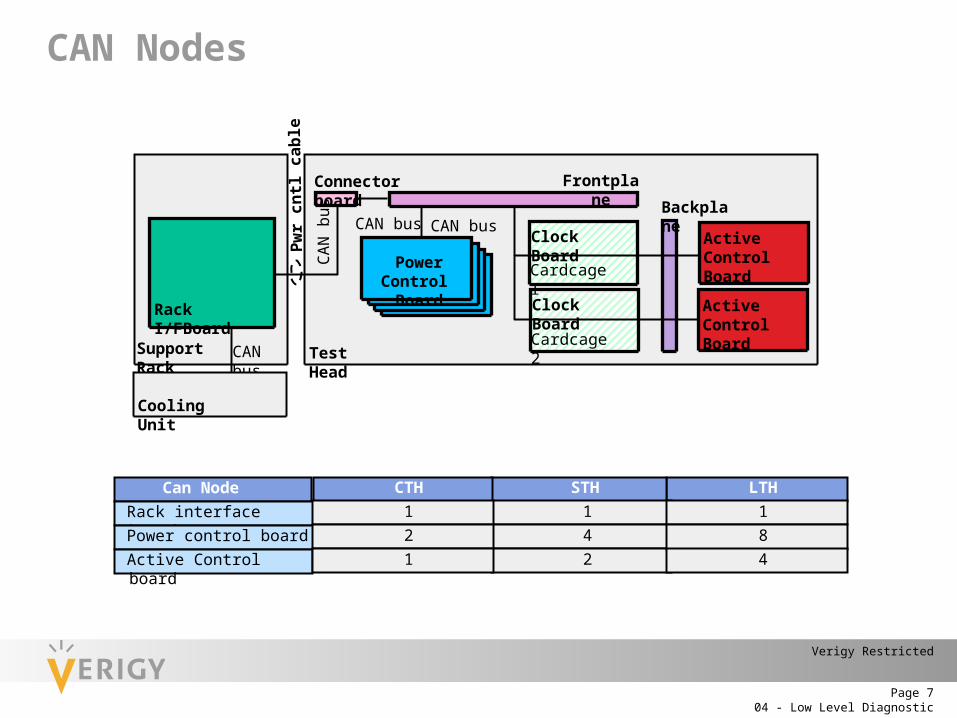
LTH
Pwr c
ntl c
able
1
Frontplane
CAN bus
Power Control Board
Rack I/FBoard
Support Rack
Connector board
Clock Board Active Control Board
Active Control Board
Clock Board
Cardcage 1
Cardcage 2
CAN bus
Test Head
Backplane
CAN
bus
CAN bus
Cooling Unit
CAN Nodes
Can Node STH
Rack interface board 1Power control board 4Active Control board 2
184
CTH
121
04 - Low Level DiagnosticPage 8
Verigy Restricted
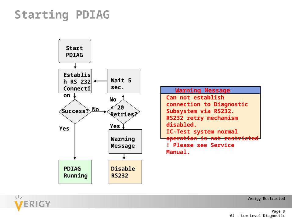
Yes
No
Yes
No
Warning MessageCan not establish connection to Diagnostic Subsystem via RS232.RS232 retry mechanism disabled.IC-Test system normal operation is not restricted ! Please see Service Manual.
Success?
PDIAGRunning
Disable RS232
Warning Message
< 20 Retries?
Wait 5 sec.Establish RS 232 Connection
Start PDIAG
Starting PDIAG
04 - Low Level DiagnosticPage 9
Verigy Restricted
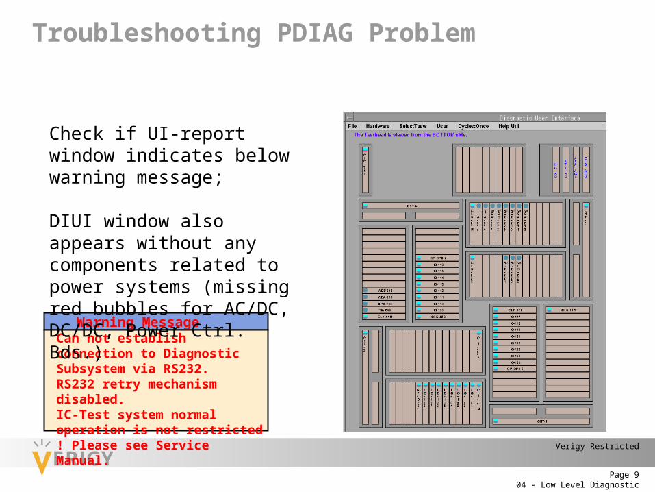
Troubleshooting PDIAG Problem
Warning MessageCan not establish connection to Diagnostic Subsystem via RS232.RS232 retry mechanism disabled.IC-Test system normal operation is not restricted ! Please see Service Manual.
Check if UI-report window indicates below warning message;
DIUI window also appears without any components related to power systems (missing red bubbles for AC/DC, DC/DC, Power Ctrl. Bds.)

04 - Low Level DiagnosticPage 10
Verigy Restricted
Yes
No
Yes
No
Yes
No
Troubleshooting PDIAG Problem
Shut down SmarTest or PDIAG
Connect / Check RS232 cable
OK?
Restart PDIAG
Restart PDIAG
Restart PDIAG
OK?
OK?
Power cycle Test System
Reboot WS Power cycle Test Head
Call Expert
04 - Low Level DiagnosticPage 11
Verigy Restricted
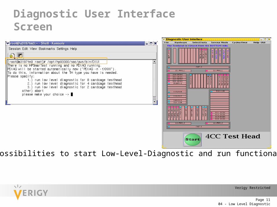
Diagnostic User Interface Screen
Two different possibilities to start Low-Level-Diagnostic and run functional tests: Via GUI Command line
04 - Low Level DiagnosticPage 12
Verigy Restricted
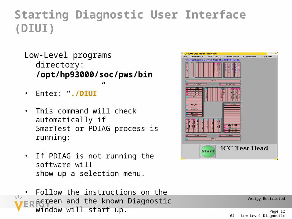
Starting Diagnostic User Interface (DIUI)
Low-Level programs directory: /opt/hp93000/soc/pws/bin
• Enter: “./DIUI”
• This command will check automatically if SmarTest or PDIAG process is running:
• If PDIAG is not running the software will show up a selection menu.
• Follow the instructions on the screen and the known Diagnostic window will start up.
• Enter into Service-Mode and select required DIS test.

04 - Low Level DiagnosticPage 13
Verigy Restricted
Starting LLD From Command LineLow-Level programs directory: /opt/hp93000/soc/pws/bin
• ./PDIAG -n -t <4/8> (-n: system S/W not running, -t: number of testhead cardcages)• ./DIFT
• load tcf file: >l /opt/hp93000/soc/pws/data/di_files/all_dd.tcf• execute a DIS test: >T xxxx xxxx: mnemonics of DIS tests
• tail –f /var/opt/hp93000/soc/diagnostic/di_log_file.<date_time>
04 - Low Level DiagnosticPage 14
Verigy Restricted
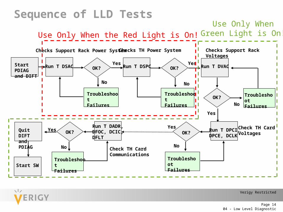
Sequence of LLD Tests
No
Yes
No
Yes
No
Yes
No
Yes
No
Yes
TroubleshootFailures
TroubleshootFailures
TroubleshootFailures
TroubleshootFailures
TroubleshootFailures
Start PDIAG and DIFT
Run T DSAC OK? OK?
OK?
OK? OK?
Run T DSPC Run T DVAC
Run T DPCI,DPCE, DCLK
Run T DADR,DFOC, DCIC,DFLT
Quit DIFT and PDIAG
Start SW
Check TH Card Voltages
Check TH CardCommunications
Checks Support Rack VoltagesChecks Support Rack Power System Checks TH Power System
Use Only When the Red Light is On!Use Only When
Green Light is On!
04 - Low Level DiagnosticPage 15
Verigy Restricted
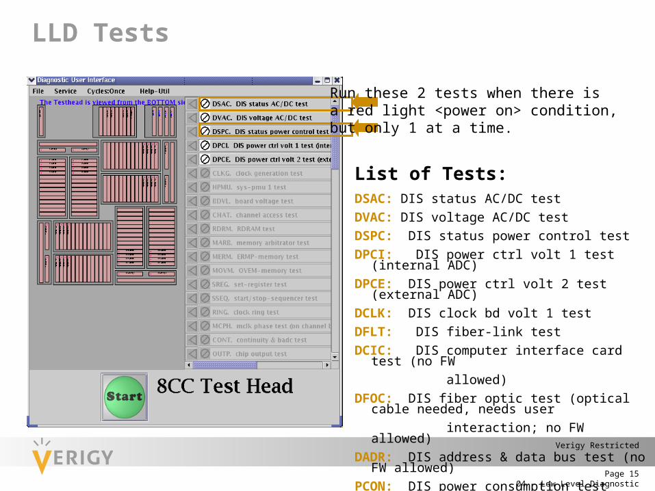
LLD Tests
Run these 2 tests when there isa red light <power on> condition,but only 1 at a time.
List of Tests:DSAC: DIS status AC/DC testDVAC: DIS voltage AC/DC testDSPC: DIS status power control testDPCI: DIS power ctrl volt 1 test (internal ADC)DPCE: DIS power ctrl volt 2 test (external ADC)DCLK: DIS clock bd volt 1 testDFLT: DIS fiber-link testDCIC: DIS computer interface card test (no FW allowed)DFOC: DIS fiber optic test (optical cable needed, needs user interaction; no FW allowed)DADR: DIS address & data bus test (no FW allowed)PCON: DIS power consumption test
04 - Low Level DiagnosticPage 16
Verigy Restricted
Low-Level-DiagnosticBest practice
• When DIUI startup fails with message: “Cannot find PDIAG process”; just re-enter again command DIUI, which will most likely startup Diagnostic GUI.
• When DIUI startup fails with message: “another PDIAG process is already running”; search for PDIAG process by using command: ps –ef | grep PDIAG and manually stop this running process: kill -9 <process-id-number of PDIAG>
• With each Low-Level-Diagnostic run only select a single subtest each.
• Sometimes Rule-Interpreter (DIRI) is not able to display a meaningful result:“Sorry, no information in knowledgebase found”, please continue in the list of Low-Level-Diagnostic subtests; just select the next test.
• Close Low-Level-Diagnostic GUI only by selecting: FILE > Close and Exit PDIAG and DIFT
• Each Diagnostic run creates the known result files; for easy navigation use the command: ll –lart to list the files by their date, when they have been created.
04 - Low Level DiagnosticPage 17
Verigy Restricted
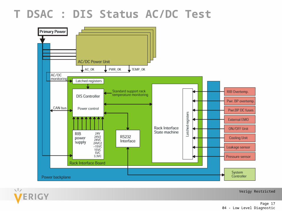
T DSAC : DIS Status AC/DC Test
04 - Low Level DiagnosticPage 18
Verigy Restricted
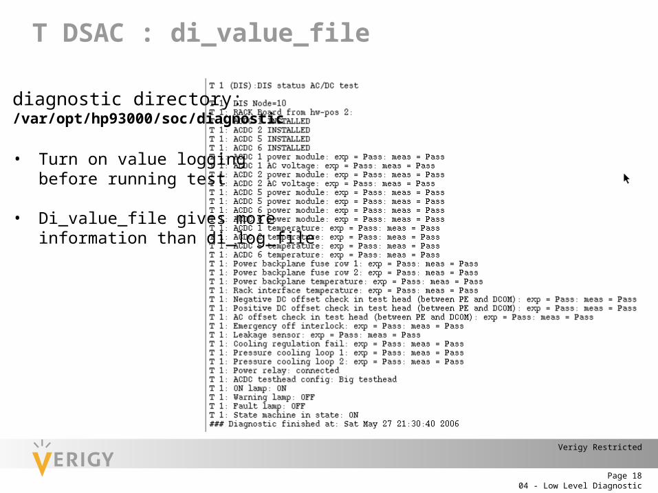
T DSAC : di_value_file
diagnostic directory: /var/opt/hp93000/soc/diagnostic
• Turn on value loggingbefore running test
• Di_value_file gives moreinformation than di_log_file
04 - Low Level DiagnosticPage 19
Verigy Restricted
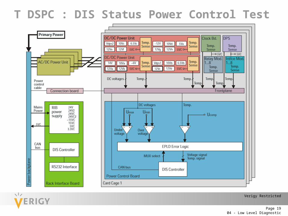
T DSPC : DIS Status Power Control Test

04 - Low Level DiagnosticPage 20
Verigy Restricted
T DSPC : value vs. log
diagnostic directory: /var/opt/hp93000/soc/diagnostic
• Turn on value loggingbefore running test
di_log_file
di_value_file
04 - Low Level DiagnosticPage 21
Verigy Restricted
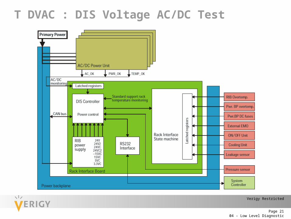
T DVAC : DIS Voltage AC/DC Test
04 - Low Level DiagnosticPage 22
Verigy Restricted
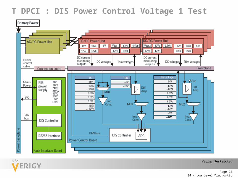
T DPCI : DIS Power Control Voltage 1 Test
04 - Low Level DiagnosticPage 23
Verigy Restricted
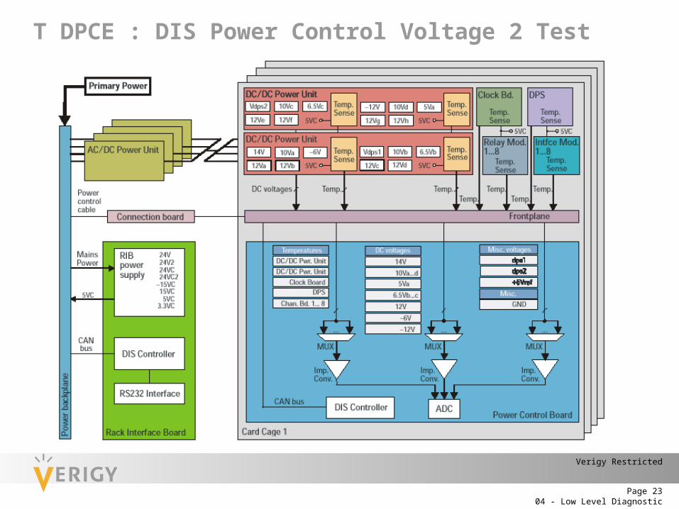
T DPCE : DIS Power Control Voltage 2 Test
04 - Low Level DiagnosticPage 24
Verigy Restricted
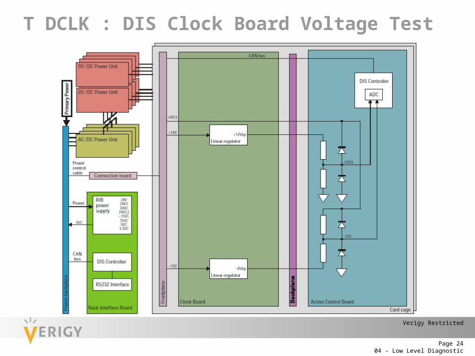
T DCLK : DIS Clock Board Voltage Test
04 - Low Level DiagnosticPage 25
Verigy Restricted
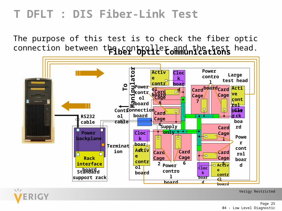
T DFLT : DIS Fiber-Link Test
The purpose of this test is to check the fiber optic connection between the controller and the test head.
Clockboard
CardCage 1
CardCage 5
Largetest head
Active controlboard
Connectionboard
CardCage 7
Card Cage 3
CardCage 6
CardCage 2
CardCage 4
Card Cage 8
Clockboard
Clockboard
Clockboard
Active controlboard
Active controlboard
Active controlboard
Control cable
Standard support rack
Rack interfaceboard
RS232cable
Power backplane
Power controlboard
Powercontrolboard
Powercontrolboard
Power controlboard
Termination
Supply onlyTo
Man
ipul
ator
Fiber Optic Communications
04 - Low Level DiagnosticPage 26
Verigy Restricted
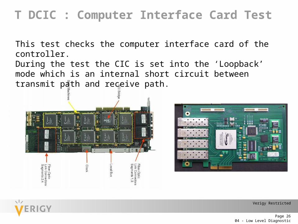
T DCIC : Computer Interface Card Test
This test checks the computer interface card of the controller. During the test the CIC is set into the ‘Loopback’ mode which is an internal short circuit between transmit path and receive path.
04 - Low Level DiagnosticPage 27
Verigy Restricted
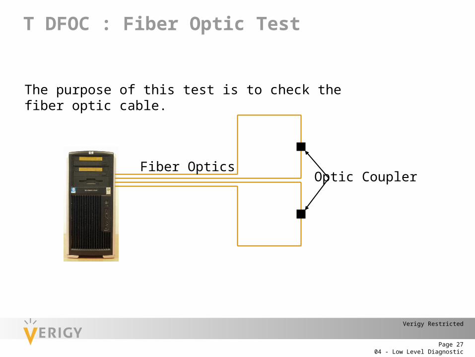
T DFOC : Fiber Optic Test
The purpose of this test is to check the fiber optic cable.
Optic CouplerFiber Optics

04 - Low Level DiagnosticPage 28
Verigy Restricted
T DADR : Address & Data Bus Test
The multiplexed address/data bus in the testhead are checked for stuck-at-0 and stuck-at-1 failures. RS232 DIS Bus
Fiber Optics
04 - Low Level DiagnosticPage 29
Verigy Restricted