verigy v93000 service training module 11: calibration robot
TRANSCRIPT
Verigy V93000Service Training
Module 11:Calibration Robot
11 - Cal RobotPage 2
Verigy Restricted
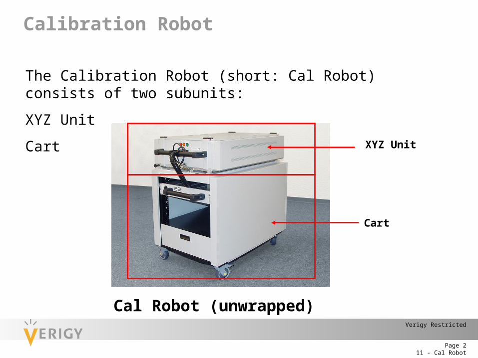
Calibration Robot
The Calibration Robot (short: Cal Robot) consists of two subunits:
XYZ Unit
Cart
Cal Robot (unwrapped)
XYZ Unit
Cart
11 - Cal RobotPage 3
Verigy Restricted
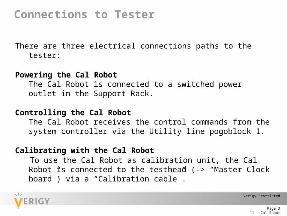
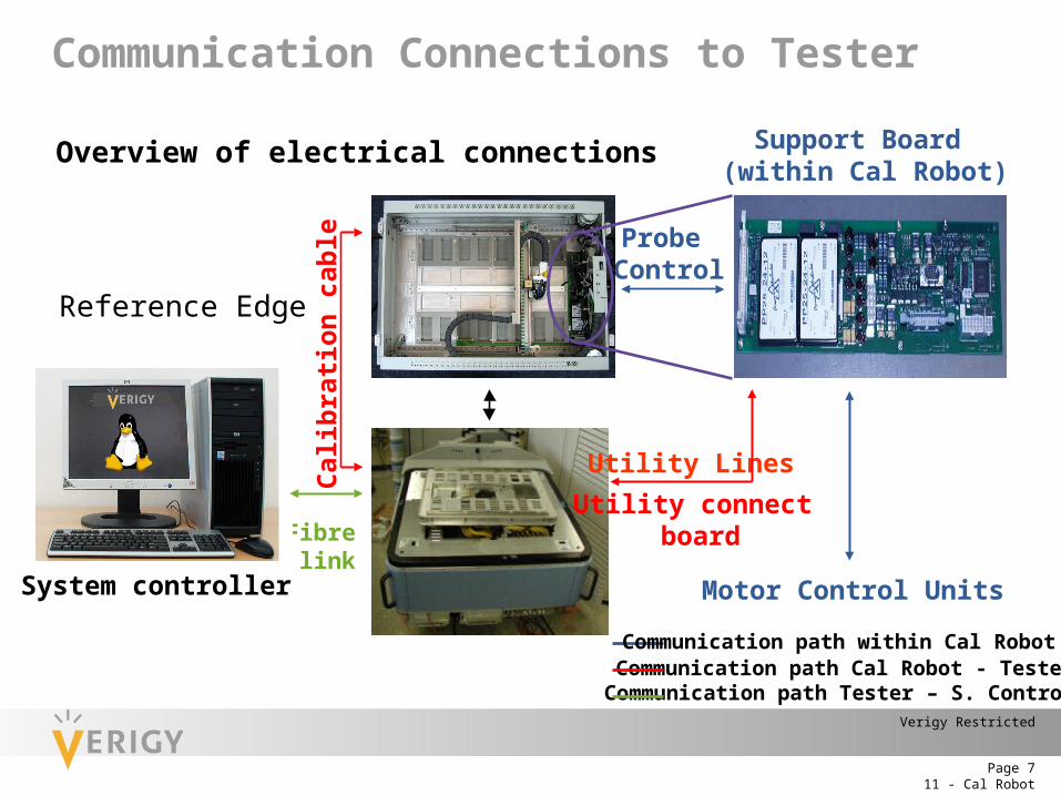
There are three electrical connections paths to the tester:
Powering the Cal RobotThe Cal Robot is connected to a switched power outlet in the Support Rack.
Controlling the Cal RobotThe Cal Robot receives the control commands from the system controller via the Utility line pogoblock 1.
Calibrating with the Cal RobotTo use the Cal Robot as calibration unit, the Cal Robot is connected to the testhead (-> “Master Clock board”) via a “Calibration cable”.
Connections to Tester
11 - Cal RobotPage 4
Verigy Restricted
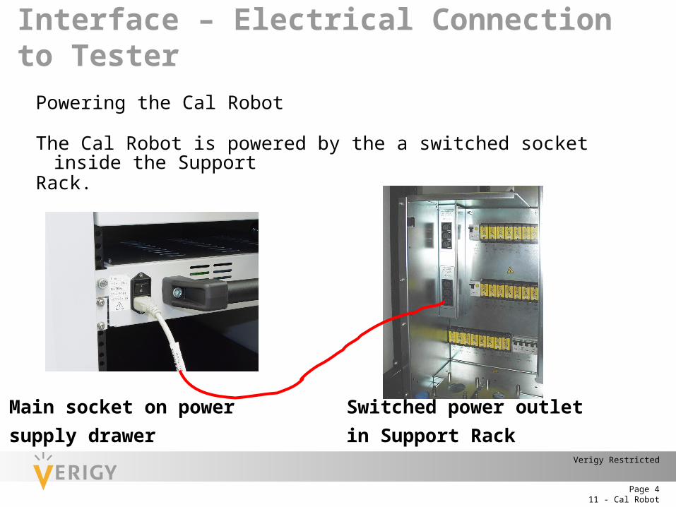
Powering the Cal Robot
The Cal Robot is powered by the a switched socket inside the SupportRack.
Main socket on power
supply drawer
Switched power outlet
in Support Rack
Interface – Electrical Connection to Tester
11 - Cal RobotPage 5
Verigy Restricted
TH PanelCalibration cable
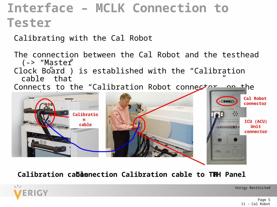
Calibrating with the Cal Robot
The connection between the Cal Robot and the testhead (-> “MasterClock Board”) is established with the “Calibration cable” thatConnects to the “Calibration Robot connector” on the testhead.
Connection Calibration cable to TH
Calibration
cable
Cal Robot connecto
r
ICU (ACU) Unit
connector
Interface – MCLK Connection to Tester
11 - Cal RobotPage 6
Verigy Restricted
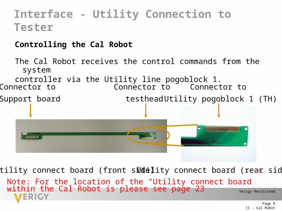
Controlling the Cal Robot
The Cal Robot receives the control commands from the systemcontroller via the Utility line pogoblock 1.
Utility connect board (front side)
Connector to
Support board
Connector to
testhead
Utility connect board (rear side)
Connector to
Utility pogoblock 1 (TH)
Note: For the location of the “Utility connect board” within the Cal Robot is please see page 23
Interface - Utility Connection to Tester
11 - Cal RobotPage 7
Verigy Restricted
Motor Control Units
Utility Lines
Reference Edge
Probe Control
System controller
Support Board (within Cal Robot)
Overview of electrical connections
Cal
ibra
tion
cabl
e
Utility connect boardFibre
link
Communication path within Cal RobotCommunication path Cal Robot - TesterCommunication path Tester – S. Controller
Communication Connections to Tester
11 - Cal RobotPage 8
Verigy Restricted
The XYZ Unit contains:• Calibration Probe
(-> calibrates all digital pins on the tester by contacting the channel pogo pins)• Support Board
(-> features the system controller, controls the Robot) • Utility Line Interface
(-> connects the Support Board with the TH)• ON/OFF Board
(->push buttons that also serve as status LEDs)• Mechanical hardware to move the Cal Probe and contact the Pogopins
(Bridge, Drive belt, stepper motors, Linear guide, Pulleys)
System components: XYZ Unit
11 - Cal RobotPage 9
Verigy Restricted
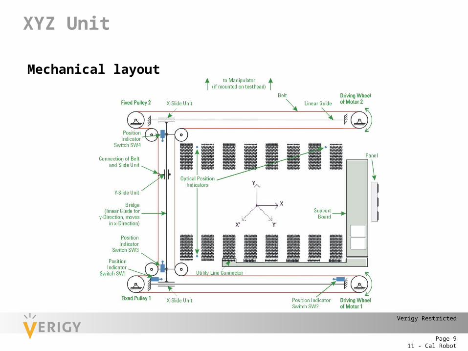
Mechanical layout
XYZ Unit
11 - Cal RobotPage 10
Verigy Restricted
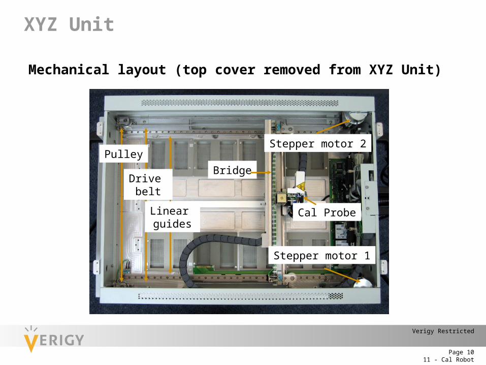
Mechanical layout (top cover removed from XYZ Unit)
Linear guides
Pulley
Drive belt
Bridge
Stepper motor 2
Stepper motor 1
Cal Probe
XYZ Unit
11 - Cal RobotPage 11
Verigy Restricted
Electrical layout (Block diagram)
XYZ Unit
M 1
Break 1
Encoder 1
M 2
Break 2
Encoder 2
Power Supply
24V
SW1..
.SW5,
Opt. S
enso
rSwitch 3(y-axis)
Switch 1(x-axis)
Switch 2(x-axis)
Switch 4(y-axis)
Switch 5(z-axis)
Switch 5
Support Board
Motor Control Unit 2
Motor Control Unit 1
Solenoid(z-axis)
TestheadFiber Link
System controller
Fiber-optic
Module
Seria
l Con
trol
24V
Optical Sensor
Cal-Probe
88 V - 264 VAC
from Support Rack
Serial Control
Reference Edge
Probe Measurement
+10V, -10V, +5V,+12V_FAN
Sync
hrono
us St
art
ON/OFF Board LEDs
Buttons
Cal Robot - XYZ Unit
Cal Robot - Cart
Testhead
System controller
Utilit
y Li
neIn
terfa
ceDi
gita
lPo
go P
insCa
l Rob
otCo
nnec
tor
11 - Cal RobotPage 12
Verigy Restricted
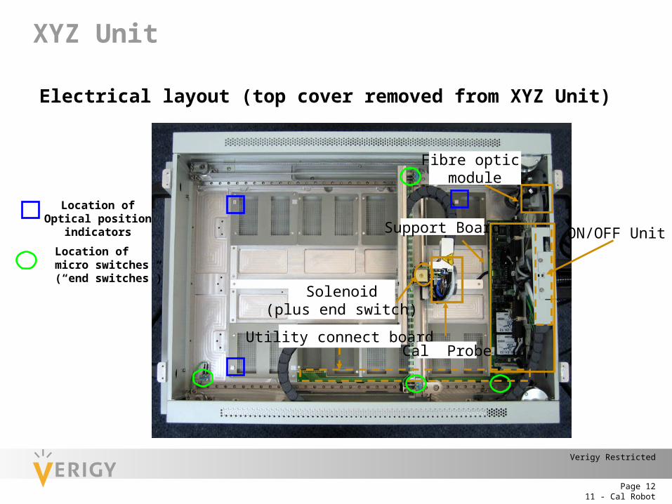
Electrical layout (top cover removed from XYZ Unit)
Location of Optical position indicators
Support Board ON/OFF Unit
Solenoid(plus end switch)
Location of micro switches (“end switches”)
Utility connect board
Fibre optic module
Cal Probe
XYZ Unit
11 - Cal RobotPage 13
Verigy Restricted
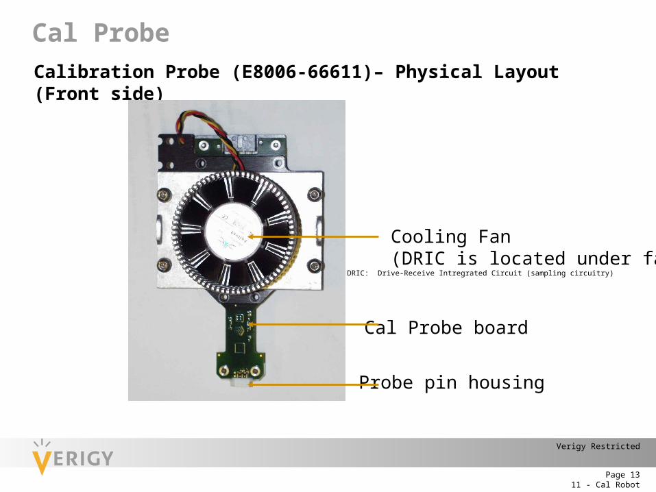
Calibration Probe (E8006-66611)– Physical Layout (Front side)
Cooling Fan (DRIC is located under fan)
Cal Probe board
Probe pin housing
Cal Probe
DRIC: Drive-Receive Intregrated Circuit (sampling circuitry)
11 - Cal RobotPage 14
Verigy Restricted
Calibration Probe – Block diagram
50
DAC
DVH
IDROOPA1
PIN2IDVL
16.2
16.2
16.2
Pogo pin
Channel 2
Logic, EEPROM
DRIC Temperature
Heatsink Temp.
Drive/ReceiveInvert
Reference Edge
+10V–10V
Fan SupplySerial interface
to support board
DRIC
+5V
Pogo pin
Channel 1
Cal Probe
11 - Cal RobotPage 15
Verigy Restricted
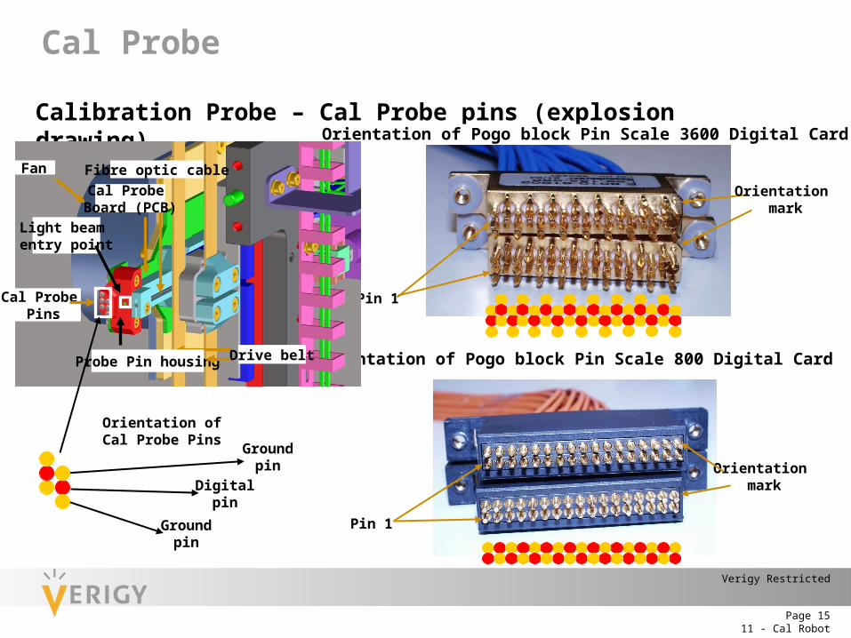
Calibration Probe – Cal Probe pins (explosion drawing)
Orientation ofCal Probe Pins
Groundpin
Groundpin
Digitalpin
Orientation of Pogo block Pin Scale 3600 Digital Card
Orientation of Pogo block Pin Scale 800 Digital Card
Orientation mark
Orientation mark
Pin 1
Pin 1
Fibre optic cable
Light beam entry point
Cal Probe Pins
Drive belt
Fan
Cal Probe Board (PCB)
Probe Pin housing
Cal Probe
11 - Cal RobotPage 16
Verigy Restricted
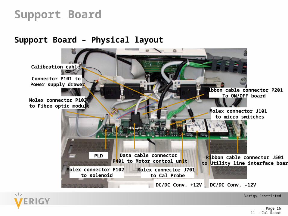
Support Board – Physical layout
Calibration cable
Connector P101 to Power supply drawer
Molex connector P103 to Fibre optic module
Molex connector P102 to solenoid
Data cable connector P401 to Motor control unit
Molex connector J701 to Cal Probe
DC/DC Conv. +12V
Ribbon cable connector J501 to Utility line interface board
Molex connector J101 to micro switches
Ribbon cable connector P201To ON/OFF board
DC/DC Conv. -12V
PLD
Support Board

11 - Cal RobotPage 17
Verigy Restricted
Support Board – Physical layout
Status LEDsDS 601 lits if +24V are presentDS 602 lits if +12V are presentDS 604 lits if +5V are presentDS 603 lits if –10V are presentDS 701 indicates that the PLD is not configured,
off after power onDS 702 indicates that PLD worksDS 703 currently not used
Support Board
11 - Cal RobotPage 18
Verigy Restricted
The drawer contains:
• Power supply (provides power to the XYZ Unit, the motor control units and the stepper motors)
• Power supply fuses (fuses protect the AC main input, the 24VDC output line to the support board and the two motor control units)
• Motor control units (control the operation of the stepper motors and breaks)
• Accessory drawer to store tools and Diag/Cal boards
Cart
11 - Cal RobotPage 19
Verigy Restricted
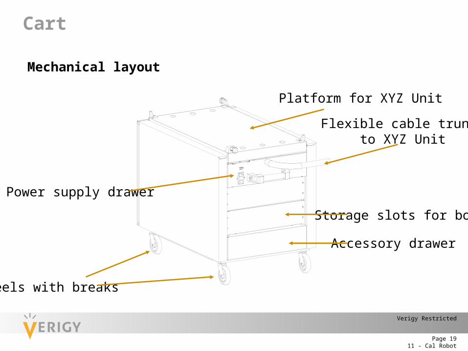
Mechanical layout
Power supply drawer
Accessory drawer
Wheels with breaks
Flexible cable trunk to XYZ Unit
Platform for XYZ Unit
Storage slots for board
Cart
11 - Cal RobotPage 20
Verigy Restricted
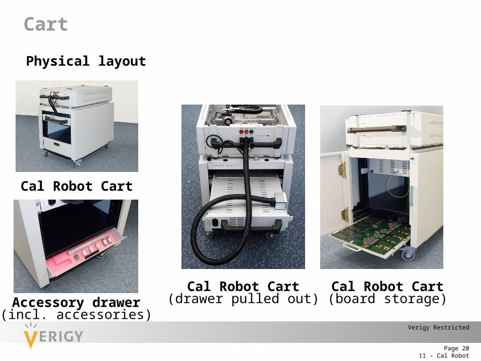
Physical layout
Cal Robot Cart
Cal Robot Cart(drawer pulled out)Accessory drawer
(incl. accessories)
Cal Robot Cart(board storage)
Cart
11 - Cal RobotPage 21
Verigy Restricted
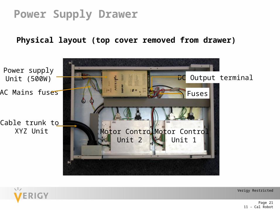
Physical layout (top cover removed from drawer)
AC Mains fuses
Power supplyUnit (500W)
Motor Control Unit 2
Motor Control Unit 1
DC Output terminal
Cable trunk to XYZ Unit
Fuses
Power Supply Drawer
11 - Cal RobotPage 22
Verigy Restricted
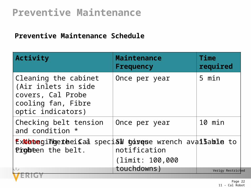
Preventive Maintenance Schedule
* Note: There is a special torque wrench available to tighten the belt.
Activity Maintenance Frequency Time required
Cleaning the cabinet (Air inlets in side covers, Cal Probe cooling fan, Fibre optic indicators)
Once per year 5 min
Checking belt tension and condition * Once per year 10 min
Exchanging the Cal Probe SW gives notification(limit: 100,000 touchdowns)
15 min
Preventive Maintenance
11 - Cal RobotPage 23
Verigy Restricted
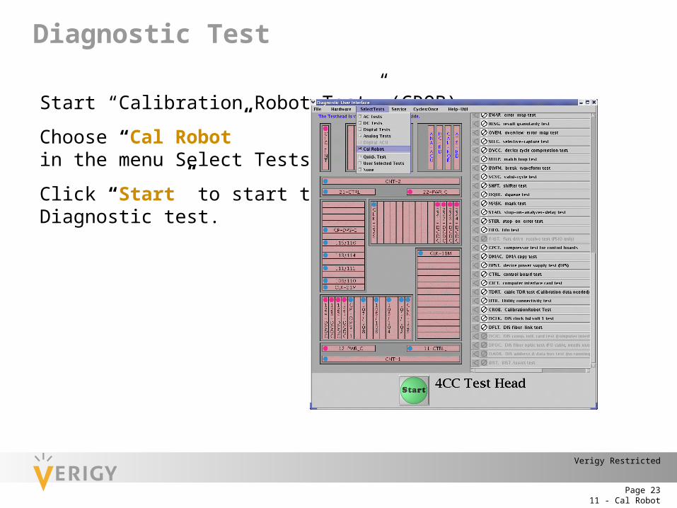
Start “Calibration Robot Test” (CROB)
Choose “Cal Robot”in the menu Select Tests
Click “Start” to start the Diagnostic test.
Diagnostic Test
11 - Cal RobotPage 24
Verigy Restricted
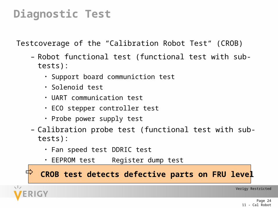
Testcoverage of the “Calibration Robot Test“ (CROB)
– Robot functional test (functional test with sub-tests):• Support board communiction test• Solenoid test• UART communication test• ECO stepper controller test• Probe power supply test
– Calibration probe test (functional test with sub-tests):• Fan speed test DDRIC test• EEPROM test Register dump test• Probe temperature test Probe DAC test
CROB test detects defective parts on FRU level
Diagnostic Test
11 - Cal RobotPage 25
Verigy Restricted
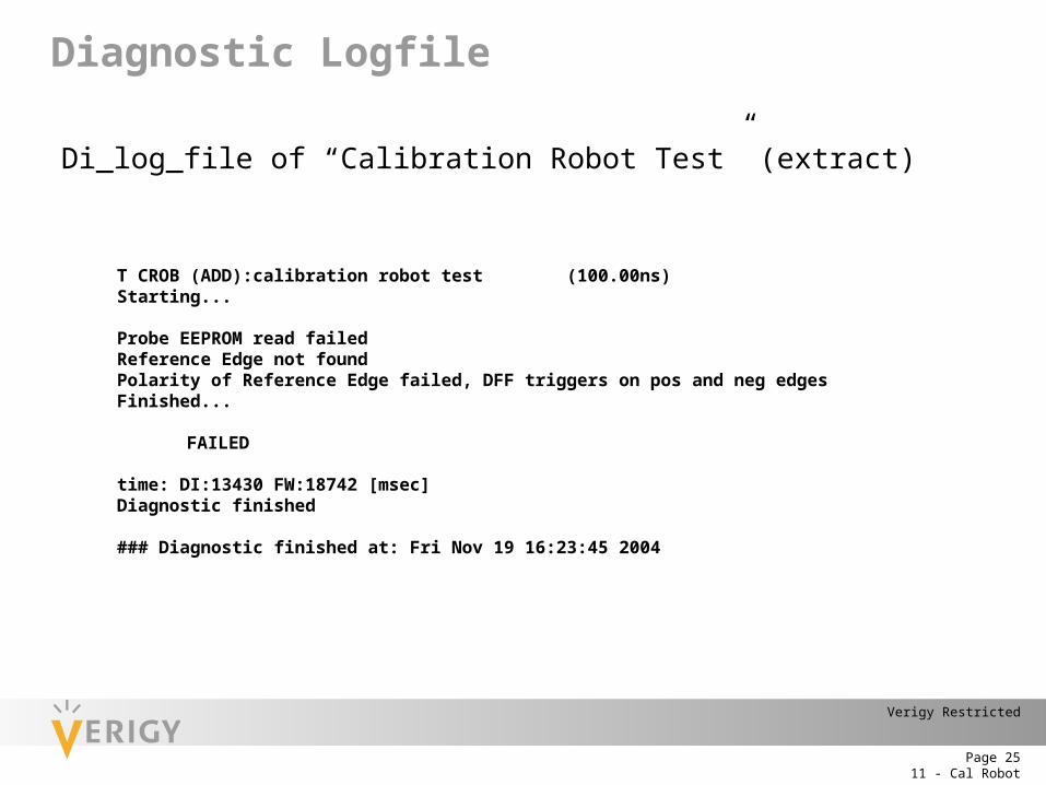
Di_log_file of “Calibration Robot Test” (extract)
T CROB (ADD):calibration robot test (100.00ns)Starting...
Probe EEPROM read failedReference Edge not foundPolarity of Reference Edge failed, DFF triggers on pos and neg edgesFinished...
FAILED
time: DI:13430 FW:18742 [msec]Diagnostic finished
### Diagnostic finished at: Fri Nov 19 16:23:45 2004
Diagnostic Logfile
11 - Cal RobotPage 26
Verigy Restricted
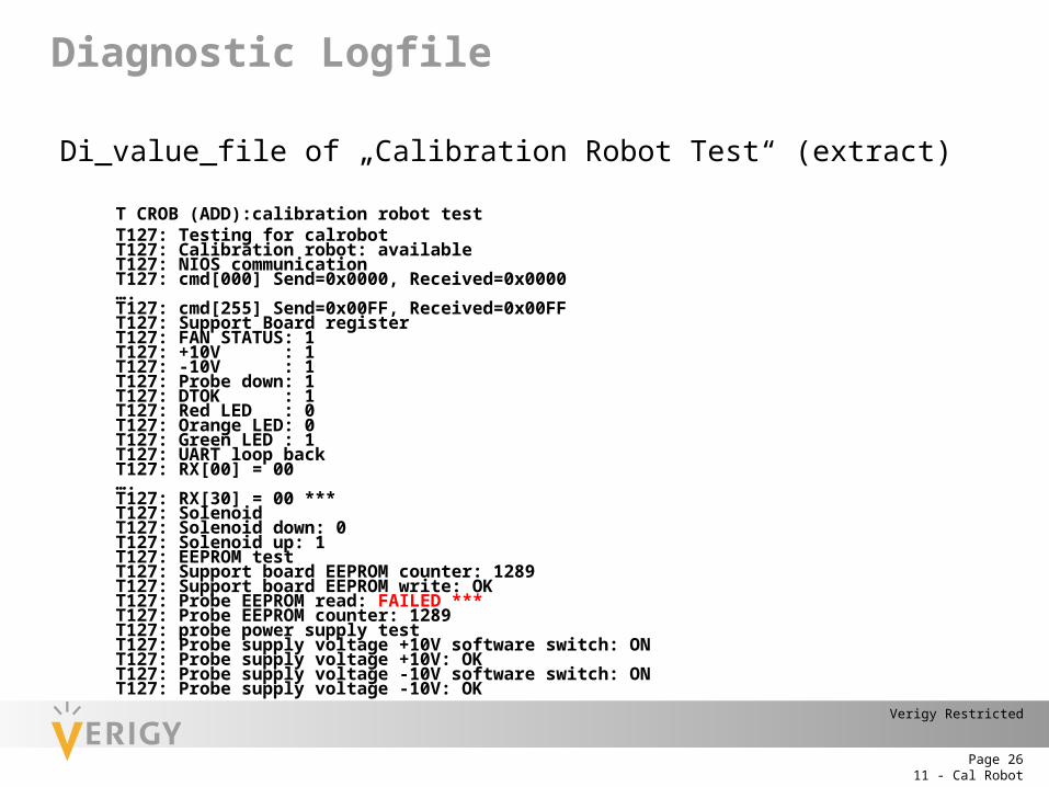
Di_value_file of „Calibration Robot Test“ (extract)
T CROB (ADD):calibration robot test T127: Testing for calrobotT127: Calibration robot: availableT127: NIOS communicationT127: cmd[000] Send=0x0000, Received=0x0000….T127: cmd[255] Send=0x00FF, Received=0x00FFT127: Support Board registerT127: FAN STATUS: 1T127: +10V : 1T127: -10V : 1T127: Probe down: 1T127: DTOK : 1T127: Red LED : 0T127: Orange LED: 0T127: Green LED : 1T127: UART loop backT127: RX[00] = 00….T127: RX[30] = 00 ***T127: SolenoidT127: Solenoid down: 0T127: Solenoid up: 1T127: EEPROM testT127: Support board EEPROM counter: 1289T127: Support board EEPROM write: OKT127: Probe EEPROM read: FAILED ***T127: Probe EEPROM counter: 1289 T127: probe power supply testT127: Probe supply voltage +10V software switch: ONT127: Probe supply voltage +10V: OKT127: Probe supply voltage -10V software switch: ONT127: Probe supply voltage -10V: OK
Diagnostic Logfile
11 - Cal RobotPage 27
Verigy Restricted
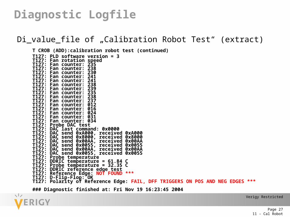
Di_value_file of „Calibration Robot Test“ (extract)T CROB (ADD):calibration robot test (continued) T127: PLD software version = 3T127: Fan rotation speedT127: Fan counter: 235 T127: Fan counter: 238 T127: Fan counter: 230 T127: Fan counter: 241 T127: Fan counter: 241 T127: Fan counter: 238 T127: Fan counter: 239 T127: Fan counter: 235 T127: Fan counter: 238 T127: Fan counter: 237 T127: Fan counter: 012 T127: Fan counter: 016 T127: Fan counter: 024 T127: Fan counter: 031 T127: Fan counter: 034 T127: Probe DAC testT127: DAC last command: 0x0000T127: DAC send 0xA000, received 0xA000T127: DAC send 0x8000, received 0x8000T127: DAC send 0x00AA, received 0x00AAT127: DAC send 0x0055, received 0x0055T127: DAC send 0x00AA, received 0x00AAT127: DAC send 0x0055, received 0x0055T127: Probe temperatureT127: DDRIC temperature = 61.84 CT127: Probe temperature = 32.35 CT127: DDRIC reference edge testT127: Reference Edge: NOT FOUND ***T127: D-Flip-Flop: OKT127: Polarity of Reference Edge: FAIL, DFF TRIGGERS ON POS AND NEG EDGES ***
### Diagnostic finished at: Fri Nov 19 16:23:45 2004
Diagnostic Logfile
11 - Cal RobotPage 28
Verigy Restricted
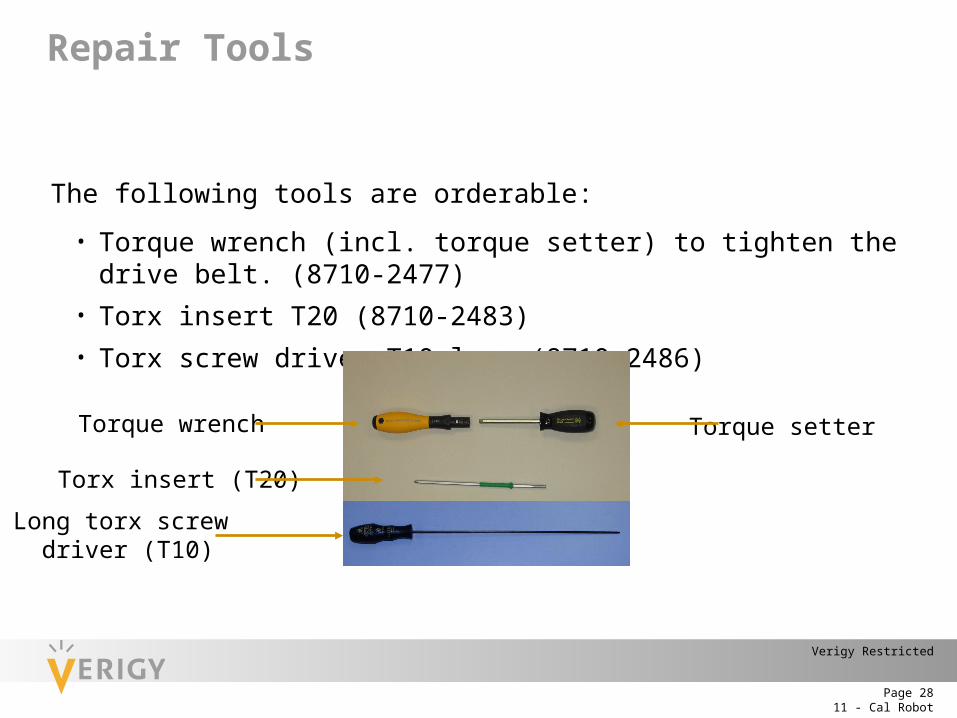
The following tools are orderable:
• Torque wrench (incl. torque setter) to tighten the drive belt. (8710-2477)• Torx insert T20 (8710-2483)• Torx screw driver T10 long (8710-2486)
Torque wrench
Torx insert (T20)
Torque setter
Long torx screw driver (T10)
Repair Tools
11 - Cal RobotPage 29
Verigy Restricted
Defective FRU: The “Calibration Robot Test” in the Diagnostic is able to detect mostdefective FRUs (exception: Power supply; for more information please referto Service Guide Part 1 (E8001-91004)
Power problems: If the ON/OFF panel is inactive after power on (e.g. lights are dark) checkthe input and output voltages of the power supply with a DVM (for moredetails please refer to Service Guide Part 2 chapter Cal Robot (E8001-91010)
Problems during initialization: If the initialization of the Cal Robot fails (i.e. all lamps on the ON/OFF board
remain on) recyle power.
Communication problem between Tester and Cal Robot: Make sure to check the connection between the Utility Pogoblock 1 and the
Utility Connect Board with in the XYZ Unit (visual inspection, check of utility lines with Diagnostic test UTIL).
Docking problem: If you encounter problems when docking the Cal Robot to the testhead please refer to manual „Calibration Robot Installation and MaintenanceGuide“ (E8006-91002)
Troubleshooting Tips
11 - Cal RobotPage 30
Verigy Restricted
Troubleshooting Cal Robot with help of ON/OFF Board
The ON/OFF board works as control panel with 3 LEDs for status indication; two buttons (red + green) are used to control the Cal Robot.
Status of LEDs:
All 3 LEDs are ON: Initialization of Cal Robot.
Red + Green LED ON: Manual mode is entered if Red+Green LED are pressed at the same time -> Motor brakes are disengaged and Cal Probe can be moved manually.
Red LED ON: hardware defect
Green + Orange LED ON: Cal Robot is in operation (e.g. init; performs AC Skew Calibration)
Green LED ON: Cal Robot is ready
Troubleshooting Tips
11 - Cal RobotPage 31
Verigy Restricted
Overview of Firmware commands:
CRSC INIT Initializes global variables.
CRCA INIT Initializes the motor control units.
CRCA SLFT Performs coarse self calibration (moves probe to end switches, moves probe up/down)
CRCA RCAL Performs fine calibration (moves to reference light sources)
CRSC? MCNT Query the counter of the Support Board EEPROM
CRSC? CCNT Query the counter on the Cal Probe EEPROM
Firmware Commands
11 - Cal RobotPage 32
Verigy Restricted
Example: Perform coarse and fine calibration, then move Cal Probe to channel 10101 and then into “park” position.
• Start SmarTest• execute: /opt/hp93000/soc/fw/bin/hpt
1. command CRSC INIT
2. command CRCA INIT
3. command CRCA SLFT
4. command CRCA RCAL
5. command CRMV CHMV,10101 (->moves Cal Probe to channel 10101 and contacts pin)
6. command CRMV PARK (-> Cal Probe enter „park“ position)
Firmware Commands
11 - Cal RobotPage 33
Verigy Restricted
Example: Read out counter of Support Board and Cal Probe EEPROM:• Start SmarTest• execute: /opt/hp93000/soc/fw/bin/hpt
1. command CRSC INIT
2. command CRSC? MCNT (-> Query the counter of the Support Board EEPROM)
3. command CRSC? CCNT (-> Query the counter on the Cal Probe EEPROM)
Example: Read out temperature of Cal Probe:• - Start SmarTest• - execute: /opt/hp93000/soc/fw/bin/hpt
1. command CRSC INIT
2. command CRPD? TMPP (-> Reads out temperature of Cal Probe)
3. command CRPD? TMPA (-> Reads out ambient temperature)
Example results:• CRPD TMPP,336,395 -> Probe has a temperature of 336,395K (= 336,395-273,16 = 62,25
°C)• CRPD TMPA,308,034 -> Ambient temperature is 308,034K (= 336,395-273,16 = 34,8 °C)
Firmware Commands
11 - Cal RobotPage 34
Verigy Restricted
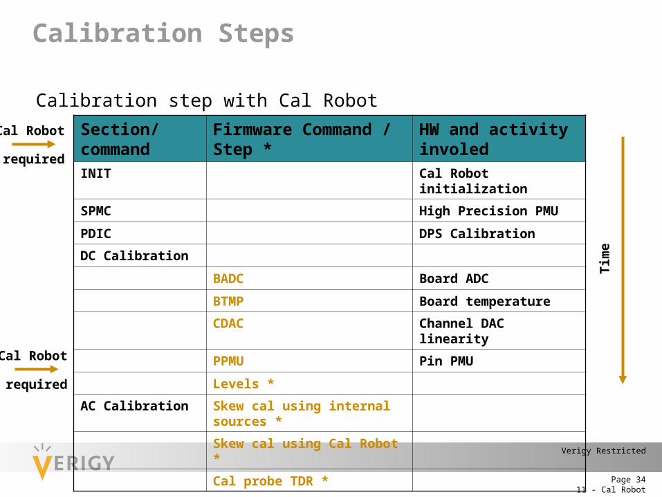
Calibration step with Cal Robot
Section/command Firmware Command / Step * HW and activity involed
INIT Cal Robot initialization
SPMC High Precision PMU
PDIC DPS Calibration
DC Calibration
BADC Board ADC
BTMP Board temperature
CDAC Channel DAC linearity
PPMU Pin PMU
Levels *
AC Calibration Skew cal using internal sources *
Skew cal using Cal Robot *
Cal probe TDR *
Cal Robot
Cal Robot
Tim
e
required
required
Calibration Steps