verifying connectivity with mpls lsp ping and … cisco nexus 7000 series nx-os mpls configuration...
TRANSCRIPT
Cisco Nexus
OL-23587-03
C H A P T E R 35
Verifying Connectivity with MPLS LSP Ping and TracerouteThis chapter describes how to verify Multiprotocol Label Switching (MPLS) connectivity with the MPLS label switched protocol (LSP) ping and traceroute feature.
This chapter includes the following sections:
• Finding Feature Information, page 35-1
• Information About MPLS LSP Ping and Traceroute, page 35-1
• Licensing Requirements for MPLS LSP Ping and Traceroute, page 35-9
• Prerequisites for MPLS LSP Ping and Traceroute, page 35-9
• Guidelines and Limitations for MPLS LSP Ping and Traceroute, page 35-9
• Configuring MPLS LSP Ping and Traceroute, page 35-10
• Troubleshooting Examples Using MPLS LSP Ping and Traceroute, page 35-23
• Additional References for MPLS LSP Ping and Traceroute, page 35-44
• Feature History for MPLS LSP Ping and Traceroute, page 35-44
Finding Feature InformationYour software release might not support all the features documented in this module. For the latest caveats and feature information, see the Bug Search Tool at https://tools.cisco.com/bugsearch/ and the release notes for your software release. To find information about the features documented in this module, and to see a list of the releases in which each feature is supported, see the “New and Changed Information” chapter or the Feature History table below.
Information About MPLS LSP Ping and TracerouteMPLS LSP ping and traceroute helps operators to monitor label switched paths (LSPs) and quickly isolate MPLS forwarding problems. You use MPLS LSP ping and traceroute to test LSP connectivity for IPv4 Label Distribution Protocol (LDP) prefixes and Resource Reservation Protocol (RSVP) traffic engineering (TE) LSPs.
35-1 7000 Series NX-OS MPLS Configuration Guide
Chapter 35 Verifying Connectivity with MPLS LSP Ping and Traceroute Information About MPLS LSP Ping and Traceroute
Internet Control Message Protocol (ICMP) ping and traceroute are used to help diagnose the root cause when a forwarding failure occurs. However, ping and traceroute might not detect LSP failures because an ICMP packet can be forwarded through IP to the destination when an LSP breakage occurs.
MPLS LSP ping and traceroute are well suited for identifying LSP breakages for the following reasons:
• An MPLS echo request packet cannot be forwarded through IP because its IP Time to Live (TTL) is set to 1 and its IP destination address field is set to a 127/8 address.
• The Forwarding Equivalence Class (FEC) being checked is not stored in the IP destination address field (as is the case of ICMP).
MPLS echo request and reply packets test LSPs. The features described in this chapter are based on the IETF RFC 4379 Detecting Multi-Protocol Label Switched (MPLS) Data Plane Failures:
• Echo request output interface control
• Echo request traffic pacing
• Echo request end-of-stack explicit-null label shimming
• Echo request request-dsmap capability
• Request-fec checking
• Depth limit reporting
The section includes the following topics:
• MPLS LSP Ping Operation, page 35-2
• Ping Draft Versions, page 35-3
• Cisco Vendor Extensions, page 35-3
• MPLS LSP Traceroute Operation, page 35-4
• MPLS Network Management with MPLS LSP Ping and MPLS LSP Traceroute, page 35-6
• IP Does Not Forward MPLS Echo Request Packets, page 35-7
• Virtual Circuit Connectivity Verification, page 35-8
MPLS LSP Ping Operation
You can use MPLS LSP echo request and reply packets to validate an LSP by using the ping mpls command.
The MPLS echo request packet is sent to a target router through the use of the appropriate label stack associated with the LSP to be validated. Use of the label stack causes the packet to be forwarded over the LSP.
The destination IP address of the MPLS echo request packet is different from the address used to select the label stack. The destination IP address is defined as a 127.x.y.z/8 address. The 127.x.y.z/8 address prevents the IP packet from being forwarded over IP to its destination if the LSP is broken.
An MPLS echo reply is sent in response to an MPLS echo request. The reply is sent as an IP packet and it is forwarded using IP, MPLS, or a combination of both types of switching. The source address of the MPLS echo reply packet is an address obtained from the router that is generating the echo reply. The destination address is the source address of the router that originated the MPLS echo request packet.
The MPLS echo reply destination port is set to the echo request source port.
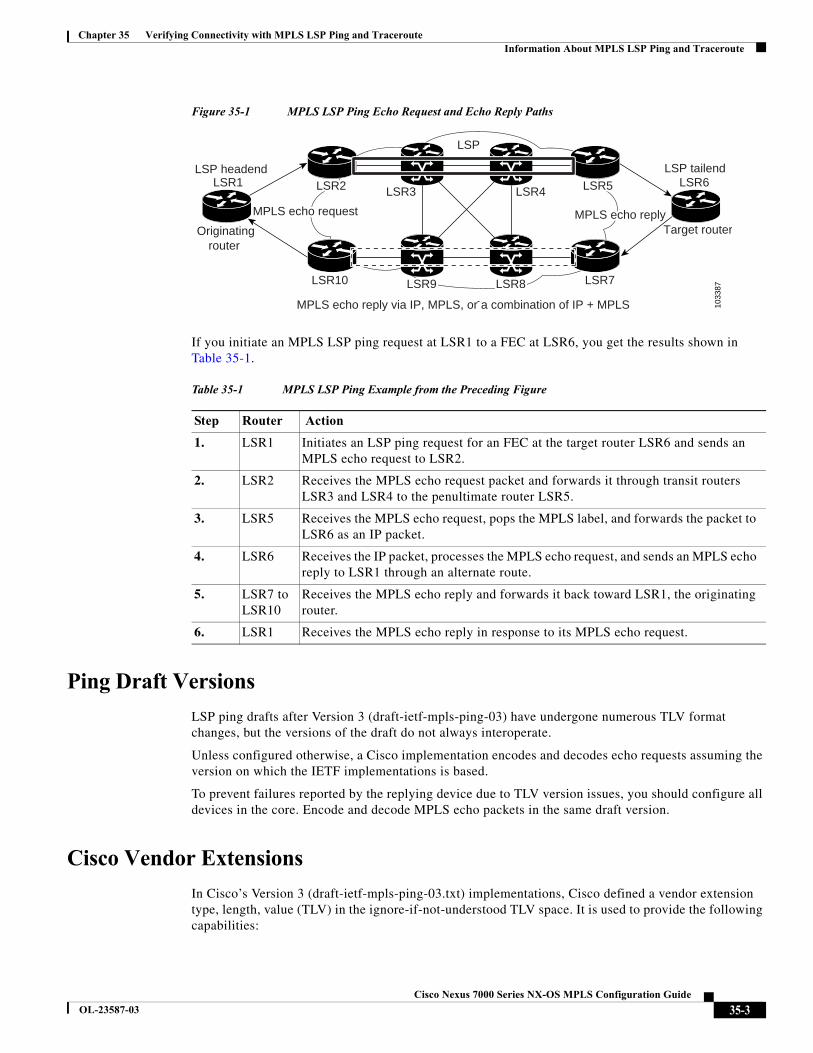
Figure 35-1 shows MPLS LSP ping echo request and echo reply paths.
35-2Cisco Nexus 7000 Series NX-OS MPLS Configuration Guide
OL-23587-03
Chapter 35 Verifying Connectivity with MPLS LSP Ping and Traceroute Information About MPLS LSP Ping and Traceroute
Figure 35-1 MPLS LSP Ping Echo Request and Echo Reply Paths
If you initiate an MPLS LSP ping request at LSR1 to a FEC at LSR6, you get the results shown in Table 35-1.
Ping Draft Versions
LSP ping drafts after Version 3 (draft-ietf-mpls-ping-03) have undergone numerous TLV format changes, but the versions of the draft do not always interoperate.
Unless configured otherwise, a Cisco implementation encodes and decodes echo requests assuming the version on which the IETF implementations is based.
To prevent failures reported by the replying device due to TLV version issues, you should configure all devices in the core. Encode and decode MPLS echo packets in the same draft version.
Cisco Vendor Extensions
In Cisco’s Version 3 (draft-ietf-mpls-ping-03.txt) implementations, Cisco defined a vendor extension type, length, value (TLV) in the ignore-if-not-understood TLV space. It is used to provide the following capabilities:
Originatingrouter
MPLS echo reply MPLS echo reply
LSR1 LSR6LSR3
LSR10 LSR7
LSR4
MPLS echo reply via IP, MPLS, or a combination of IP + MPLS
LSP headend LSP tailend
LSP
Target router MPLS echo reply MPLS echo request MPLS echo request MPLS echo request
1033
87
LSR2LSR2 LSR5LSR5
LSR9LSR9 LSR8LSR8
LSR2 LSR5
LSR9 LSR8
Table 35-1 MPLS LSP Ping Example from the Preceding Figure
Step Router Action
1. LSR1 Initiates an LSP ping request for an FEC at the target router LSR6 and sends an MPLS echo request to LSR2.
2. LSR2 Receives the MPLS echo request packet and forwards it through transit routers LSR3 and LSR4 to the penultimate router LSR5.
3. LSR5 Receives the MPLS echo request, pops the MPLS label, and forwards the packet to LSR6 as an IP packet.
4. LSR6 Receives the IP packet, processes the MPLS echo request, and sends an MPLS echo reply to LSR1 through an alternate route.
5. LSR7 to LSR10
Receives the MPLS echo reply and forwards it back toward LSR1, the originating router.
6. LSR1 Receives the MPLS echo reply in response to its MPLS echo request.
35-3Cisco Nexus 7000 Series NX-OS MPLS Configuration Guide
OL-23587-03
Chapter 35 Verifying Connectivity with MPLS LSP Ping and Traceroute Information About MPLS LSP Ping and Traceroute
• Provides an ability to track TVL versions—This capability was defined before the existence of the global configuration command for setting the echo packet encode and decode behavior. The TLV version information in an echo packet overrides the configured decoding behavior. Using this TLV for TLV versions is no longer required since the introduction of the global configuration capability.
• Provides an experimental reply Type of Service (ToS)—This capability controls the reply differentiated services code point (DSCP). Because Draft Version 8 defines a reply ToS TLV, the use of the reply DSCP is no longer required.
You enable compatibility between the MPLS LSP and ping or traceroute implementation by customizing the default behavior of echo packets.
MPLS LSP Traceroute Operation
MPLS LSP traceroute uses MPLS echo request and reply packets to validate an LSP. You can use MPLS LSP traceroute to validate IPv4 LDP and IPv4 RSVP FECs by using appropriate keywords and arguments with the traceroute mpls command.
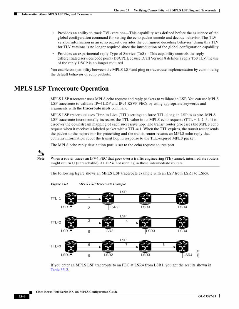
MPLS LSP traceroute uses Time-to-Live (TTL) settings to force TTL along an LSP to expire. MPLS LSP traceroute incrementally increases the TTL value in its MPLS echo requests (TTL = 1, 2, 3, 4) to discover the downstream mapping of each successive hop. The transit router processes the MPLS echo request when it receives a labeled packet with a TTL = 1. When the TTL expires, the transit router sends the packet to the supervisor for processing and the transit router returns an MPLS echo reply that contains information about the transit hop in response to the TTL-expired MPLS packet.
The MPLS echo reply destination port is set to the echo request source port.
Note When a router traces an IPV4 FEC that goes over a traffic engineering (TE) tunnel, intermediate routers might return U (unreachable) if LDP is not running in those intermediate routers.
The following figure shows an MPLS LSP traceroute example with an LSP from LSR1 to LSR4.
Figure 35-2 MPLS LSP Traceroute Example
If you enter an MPLS LSP traceroute to an FEC at LSR4 from LSR1, you get the results shown in Table 35-2.
LSR1 2
1TTL=1
LSR2
LSP
LSP
LSP
LSR3 LSR4
1033
88
LSR1 5
3 4TTL=2
LSR2 LSR3 LSR4
LSR1 9
6 7 8TTL=3
LSR2 LSR3 LSR4
35-4Cisco Nexus 7000 Series NX-OS MPLS Configuration Guide
OL-23587-03
Chapter 35 Verifying Connectivity with MPLS LSP Ping and Traceroute Information About MPLS LSP Ping and Traceroute
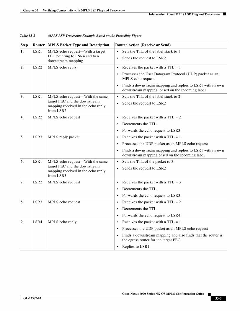
Table 35-2 MPLS LSP Traceroute Example Based on the Preceding Figure
Step Router MPLS Packet Type and Description Router Action (Receive or Send)
1. LSR1 MPLS echo request—With a target FEC pointing to LSR4 and to a downstream mapping
• Sets the TTL of the label stack to 1
• Sends the request to LSR2
2. LSR2 MPLS echo reply • Receives the packet with a TTL = 1
• Processes the User Datagram Protocol (UDP) packet as an MPLS echo request
• Finds a downstream mapping and replies to LSR1 with its own downstream mapping, based on the incoming label
3. LSR1 MPLS echo request—With the same target FEC and the downstream mapping received in the echo reply from LSR2
• Sets the TTL of the label stack to 2
• Sends the request to LSR2
4. LSR2 MPLS echo request • Receives the packet with a TTL = 2
• Decrements the TTL
• Forwards the echo request to LSR3
5. LSR3 MPLS reply packet • Receives the packet with a TTL = 1
• Processes the UDP packet as an MPLS echo request
• Finds a downstream mapping and replies to LSR1 with its own downstream mapping based on the incoming label
6. LSR1 MPLS echo request—With the same target FEC and the downstream mapping received in the echo reply from LSR3
• Sets the TTL of the packet to 3
• Sends the request to LSR2
7. LSR2 MPLS echo request • Receives the packet with a TTL = 3
• Decrements the TTL
• Forwards the echo request to LSR3
8. LSR3 MPLS echo request • Receives the packet with a TTL = 2
• Decrements the TTL
• Forwards the echo request to LSR4
9. LSR4 MPLS echo reply • Receives the packet with a TTL = 1
• Processes the UDP packet as an MPLS echo request
• Finds a downstream mapping and also finds that the router is the egress router for the target FEC
• Replies to LSR1
35-5Cisco Nexus 7000 Series NX-OS MPLS Configuration Guide
OL-23587-03
Chapter 35 Verifying Connectivity with MPLS LSP Ping and Traceroute Information About MPLS LSP Ping and Traceroute
MPLS Network Management with MPLS LSP Ping and MPLS LSP Traceroute
To manage an MPLS network, you must be able to monitor LSPs and quickly isolate MPLS forwarding problems. You need ways to characterize the liveliness of an LSP and reliably detect when an LSP fails to deliver user traffic.
You can use MPLS LSP ping to verify the LSP that is used to transport packets destined for IPv4 LDP prefixes. You can use MPLS LSP traceroute to trace LSPs that are used to carry packets destined for IPv4 LDP prefixes.
An MPLS echo request is sent through an LSP to validate it. A TTL expiration or LSP breakage causes the transit router to process the echo request before it gets to the intended destination. The router returns an MPLS echo reply that contains an explanatory reply code to the originator of the echo request.
The successful echo request is processed at the egress of the LSP. The echo reply is sent through an IP path, an MPLS path, or a combination of both back to the originator of the echo request.
Information Provided by the Router Processing LSP Ping or LSP Traceroute
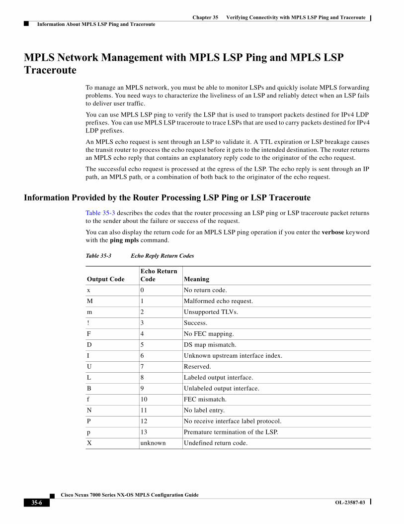
Table 35-3 describes the codes that the router processing an LSP ping or LSP traceroute packet returns to the sender about the failure or success of the request.
You can also display the return code for an MPLS LSP ping operation if you enter the verbose keyword with the ping mpls command.
Table 35-3 Echo Reply Return Codes
Output CodeEcho Return Code Meaning
x 0 No return code.
M 1 Malformed echo request.
m 2 Unsupported TLVs.
! 3 Success.
F 4 No FEC mapping.
D 5 DS map mismatch.
I 6 Unknown upstream interface index.
U 7 Reserved.
L 8 Labeled output interface.
B 9 Unlabeled output interface.
f 10 FEC mismatch.
N 11 No label entry.
P 12 No receive interface label protocol.
p 13 Premature termination of the LSP.
X unknown Undefined return code.
35-6Cisco Nexus 7000 Series NX-OS MPLS Configuration Guide
OL-23587-03
Chapter 35 Verifying Connectivity with MPLS LSP Ping and Traceroute Information About MPLS LSP Ping and Traceroute
Note Echo return codes 6 and 7 are accepted only for Version 3 (draft-ieft-mpls-ping-03). For version_3, these return codes have the following meaning:
• Code 6: The replying router is one of the downstream routers and its mapping for this FEC on the received interface is the given label.
• Code 7: The replying router is one of the downstream routers, but its mapping for this FEC is not the given label.
IP Does Not Forward MPLS Echo Request Packets
MPLS echo request packets that are sent during an LSP ping are never forwarded by IP. The IP header destination address field in an MPLS echo request packet is a 127.x.y.z/8 address. Routers should not forward packets using a 127.x.y.z/8 address. The 127.x.y.z/8 address corresponds to an address for the local host.
Using a 127.x.y.z address as the destination address of the UDP packet is significant because the MPLS echo request packet might fail to make it to the target router if the transit router does not label switch the LSP. Using a 127.x.y.z address allows for the detection of LSP breakages. The following occurs at the transit router:
• If an LSP breakage occurs at a transit router, the MPLS echo packet is not forwarded; it is consumed by the router.
• If the LSP is intact, the MPLS echo packet reaches the target router and is processed by the terminal point of the LSP.
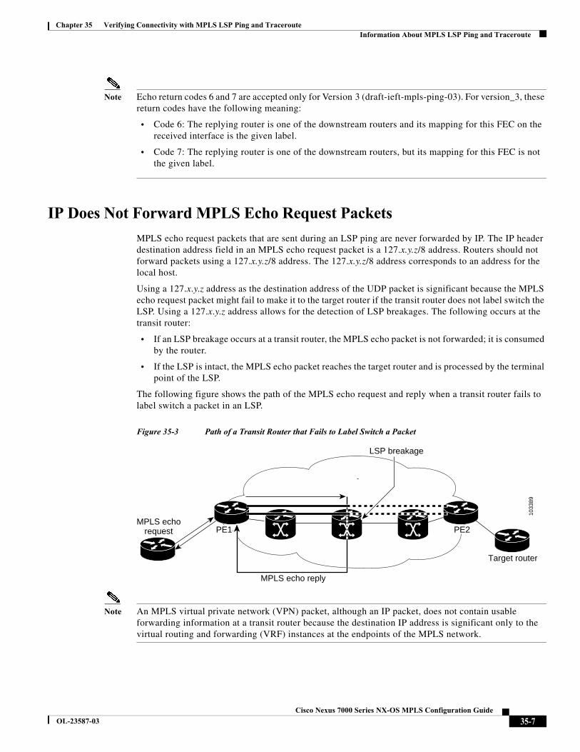
The following figure shows the path of the MPLS echo request and reply when a transit router fails to label switch a packet in an LSP.
Figure 35-3 Path of a Transit Router that Fails to Label Switch a Packet
Note An MPLS virtual private network (VPN) packet, although an IP packet, does not contain usable forwarding information at a transit router because the destination IP address is significant only to the virtual routing and forwarding (VRF) instances at the endpoints of the MPLS network.
MPLS echorequest
LSP breakage
Target router
PE2PE2PE1PE1 PE2PE1
MPLS echo reply
1033
89
35-7Cisco Nexus 7000 Series NX-OS MPLS Configuration Guide
OL-23587-03
Chapter 35 Verifying Connectivity with MPLS LSP Ping and Traceroute Information About MPLS LSP Ping and Traceroute
Virtual Circuit Connectivity Verification
Virtual Circuit Connectivity Verification (VCCV) in Layer 2 VPN Operations, Administration, and Maintenance (OAM) is used for fault detection and diagnostic of the pseudowire (PW). VCCV defines a set of messages that are exchanged on the PW to verify the connectivity. VCCV messages should be encapsulated so that the messages traverse the same path as the normal data in a network. VCCV also defines the use of the out-of-band to send VCCV messages. The Control Channel (CC) types defined for VCCV are as follows:
• Type 1—Uses a control word with 0001b as the first nibble. The VCCV packets traverse the same path as the data on the network. Type 1 cannot be used when the control word is not used in the pseudowire.
• Type 2—Uses a Router Alert Label in the encapsulation. Because a new label is added between the VC label and tunnel label(s), the packets might not be able to follow the same path as the data because of the equal cost multipath (ECMP) hashing in the core routers. Type 2 is the preferred method when the control word is not used in the pseudowire.
• Type 3—Uses Time To Live (TTL) in the Virtual Circuit (VC) label. Type 3 is used when the control word is used in the pseudowire.
Once the VCCV packet is delivered to the endpoint of the pseudowire, the Connectivity Verification (CV) types are used to determine the type of VCCV message. The following types of messages are defined for VCCV:
• Internet Control Message Protocol (ICMP) ping
• Label switch path (LSP) ping
• Bidirectional Forwarding Detection (BFD) for pseudowire fault detection
• BFD for pseudowire fault detection and status signaling
• BFD for pseudowire fault detection only without an IP header
• BFD for pseudowire fault detection and status signaling without an IP header
VCCV defines a set of messages that are exchanged between PEs to verify connectivity of the pseudowire. To make sure that pseudowire packets follow the same path as the data flow, they are encapsulated with the same labels. You can use VCCV as a diagnostic tool or as a fault detection tool.
In the diagnostic mode, you can trigger the LSP ping or ICMP ping modes depending on the underlying Public Services Network (PSN). Because a pseudowire is bidirectional, you should require that the reply be sent over the PSN tunnel that makes up the other half of the PW under test. For example, if the PSN is an MPLS LSP, send the reply on the LSP that represents the reverse path. If this process fails, you can use other reply modes to determine what is wrong.
The fault detection mode enables you to emulate a fault for detection mechanisms in other technologies, such as asynchronous transfer mode (ATM). In the fault detection mode, the upstream provider edge (PE) sends BFD control messages periodically. When the downstream PE does not receive these messages for a defined period of time, it declares that direction of the PW as down and notifies the upstream PE. Based on the emulated service, the PEs may send indications over the related attachment circuits to notify the end points of the fault condition.
35-8Cisco Nexus 7000 Series NX-OS MPLS Configuration Guide
OL-23587-03
Chapter 35 Verifying Connectivity with MPLS LSP Ping and Traceroute Licensing Requirements for MPLS LSP Ping and Traceroute
Licensing Requirements for MPLS LSP Ping and Traceroute
Prerequisites for MPLS LSP Ping and TracerouteMPLS LSP ping and traceroute have the following prerequisites:
• You must install the MPLS license.
• Before you can run MPLS LSP ping and traceroute, ensure that the Intrusion Detection System (IDS) is disabled, specifically the option that drops packets if the IP address is in the reserved 127.x.x.x range.
• You must enable the MPLS LDP feature or the MPLS traffic engineering (TE) feature.
Guidelines and Limitations for MPLS LSP Ping and Traceroute
MPLS LSP ping and traceroute have the following configuration guidelines and limitations:
• You cannot use MPLS LSP ping to validate or trace MPLS VPNs.
• You cannot use MPLS LSP traceroute to troubleshoot LSPs that use TTL hiding.
• MPLS supports per-destination and per-packet (round robin) load balancing. If per-packet load balancing is in effect, you should not use MPLS LSP traceroute because during an LSP traceroute, a transit router makes consistency checks on the information supplied in the previous echo response from the directly connected upstream router. When you use round robin, you cannot control the path that an echo request packet takes in a way that allows a packet to be directed to TTL expire at a given router. Without that ability, the consistency check might fail during an LSP traceroute, and a consistency check failure return code might appear.
• A platform must support LSP ping and traceroute in order to respond to an MPLS echo request packet.
• Unless you enable the MPLS LSP Ping/Traceroute for LDP/TE feature along the entire path, you cannot get a reply if the request fails along the path at any node.
• The draft version on other devices in the network must be compatible with the draft version implemented on Cisco NX-OS. Earlier versions might not be compatible with later versions because of changes to type, length, and values (TLVs) without sufficient versioning information.
• You cannot use MPLS LSP traceroute to trace the path taken by Any Transport over MPLS (AToM) packets. However, you can use MPLS LSP traceroute to troubleshoot the Interior Gateway Protocol (IGP) LSP that is used by AToM.
• You cannot use MPLS LSP traceroute to troubleshoot LSPs that employ Time-to-Live (TTL) hiding. If you want to use MPLS LSP traceroute, the network should not use TTL hiding.
Product License Requirement
Cisco NX-OS MPLS LSP ping and traceroute require an MPLS license. For a complete explanation of the Cisco NX-OS licensing scheme and how to obtain and apply licenses, see the Cisco NX-OS Licensing Guide.
35-9Cisco Nexus 7000 Series NX-OS MPLS Configuration Guide
OL-23587-03
Chapter 35 Verifying Connectivity with MPLS LSP Ping and Traceroute Configuring MPLS LSP Ping and Traceroute
Configuring MPLS LSP Ping and TracerouteThis section includes the following topics:
• Enabling Compatibility Between the MPLS LSP and Ping or Traceroute Implementation, page 35-10
• Validating an LDP IPv4 FEC, page 35-11
• Validating a Layer 2 FEC, page 35-12
• Using DSCP to Request a Specific Class of Service in an Echo Reply, page 35-12
• Controlling How a Responding Router Replies to an MPLS Echo Request, page 35-13
• Preventing Loops When Using MPLS LSP Ping and LSP Traceroute Command Options, page 35-15
• Detecting LSP Breaks, page 35-16
Enabling Compatibility Between the MPLS LSP and Ping or Traceroute Implementation
LSP ping drafts after Version 3 (draft-ietf-mpls-ping-03) have undergone many TLV format changes, but the versions of the draft do not always interoperate.
Unless configured otherwise, a Cisco implementation encodes and decodes echo requests by assuming the version on which the IETF implementations are based.
To ensure interoperability among devices and prevent failures reported by the replying router due to TLV version issues, you should configure all routers in the core to encode and decode MPLS echo packets in the same draft version. For example, if the network is running RFC 4379 (Cisco Version 4) implementations but one router is capable of only Version 3 (Cisco Revision 3), configure all routers in the network to operate in Revision 3 mode.
Cisco Vendor Extensions
In Cisco’s Version 3 (draft-ietf-mpls-ping-03.txt) implementations, Cisco defined a vendor extension TLV in the ignore-if-not-understood TLV space. It is used for the following purposes:
• Provide an ability to track TLV versions.
• Provide an experimental Reply type of service (ToS) capability.
The first capability was defined before the existence of the global configuration command for setting the echo packet encode and decode behavior. TLV version information in an echo packet overrides the configured decoding behavior. Using this TLV for TLV versions is no longer required since the introduction of the global configuration capability.
The second capability controls the reply DSCP. Draft Version 8 defines a Reply ToS TLV, so the use of the reply DSCP is no longer required.
SUMMARY STEPS
1. configure terminal
2. mpls oam
3. echo revision {3 | 4}
4. echo vendor-extension
35-10Cisco Nexus 7000 Series NX-OS MPLS Configuration Guide
OL-23587-03
Chapter 35 Verifying Connectivity with MPLS LSP Ping and Traceroute Configuring MPLS LSP Ping and Traceroute
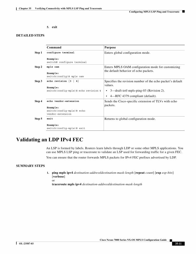
5. exit
DETAILED STEPS
Validating an LDP IPv4 FEC
An LSP is formed by labels. Routers learn labels through LDP or some other MPLS applications. You can use MPLS LSP ping or traceroute to validate an LSP used for forwarding traffic for a given FEC.
You can ensure that the router forwards MPLS packets for IPv4 FEC prefixes advertised by LDP.
SUMMARY STEPS
1. ping mpls ipv4 destination-address/destination-mask-length [repeat count] [exp exp-bits] [verbose]ortraceroute mpls ipv4 destination-address/destination-mask-length
Command Purpose
Step 1 configure terminal
Example: switch# configure terminal
Enters global configuration mode.
Step 2 mpls oam
Example: switch(config)# mpls oam
Enters MPLS OAM configuration mode for customizing the default behavior of echo packets.
Step 3 echo revision {3 | 4}
Example: switch(config-mpls)# echo revision 4
Specifies the revision number of the echo packet’s default values.
• 3—draft-ietf-mpls-ping-03 (Revision 2).
• 4—RFC 4379 compliant (default).
Step 4 echo vendor-extension
Example: switch(config-mpls)# echo vendor-extension
Sends the Cisco-specific extension of TLVs with echo packets.
Step 5 exit
Example: switch(config-mpls)# exit
Returns to global configuration mode.
35-11Cisco Nexus 7000 Series NX-OS MPLS Configuration Guide
OL-23587-03
Chapter 35 Verifying Connectivity with MPLS LSP Ping and Traceroute Configuring MPLS LSP Ping and Traceroute
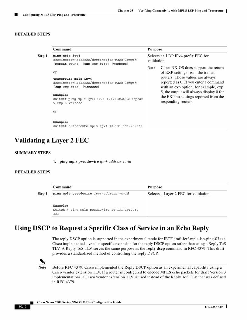
DETAILED STEPS
Validating a Layer 2 FEC
SUMMARY STEPS
1. ping mpls pseudowire ipv4-address vc-id
DETAILED STEPS
Using DSCP to Request a Specific Class of Service in an Echo Reply
The reply DSCP option is supported in the experimental mode for IETF draft-ietf-mpls-lsp-ping-03.txt. Cisco implemented a vendor-specific extension for the reply DSCP option rather than using a Reply ToS TLV. A Reply ToS TLV serves the same purpose as the reply dscp command in RFC 4379. This draft provides a standardized method of controlling the reply DSCP.
Note Before RFC 4379, Cisco implemented the Reply DSCP option as an experimental capability using a Cisco vendor extension TLV. If a router is configured to encode MPLS echo packets for draft Version 3 implementations, a Cisco vendor extension TLV is used instead of the Reply ToS TLV that was defined in RFC 4379.
Command Purpose
Step 1 ping mpls ipv4 destination-address/destination-mask-length [repeat count] [exp exp-bits] [verbose]
or
traceroute mpls ipv4 destination-address/destination-mask-length [exp exp-bits] [verbose]
Example: switch# ping mpls ipv4 10.131.191.252/32 repeat 5 exp 5 verbose
or
Example: switch# traceroute mpls ipv4 10.131.191.252/32
Selects an LDP IPv4 prefix FEC for validation.
Note Cisco NX-OS does support the return of EXP settings from the transit routers. Those values are always reported as 0. If you enter a command with an exp option, for example, exp 5, the output will always display 0 for the EXP bit settings reported from the responding routers.
Command Purpose
Step 1 ping mpls pseudowire ipv4-address vc-id
Example: Switch # ping mpls pseudowire 10.131.191.252 333
Selects a Layer 2 FEC for validation.
35-12Cisco Nexus 7000 Series NX-OS MPLS Configuration Guide
OL-23587-03
Chapter 35 Verifying Connectivity with MPLS LSP Ping and Traceroute Configuring MPLS LSP Ping and Traceroute
When Cisco NX-OS is configured to operate in revision 3 mode, it will still send using the Cisco vendor extension TLV. The software will also respond to any echo request packets with these TLVs.
SUMMARY STEPS
1. ping mpls ipv4 destination-address/destination-mask-length [reply dscp dscp-value]ortraceroute mpls ipv4 destination-address/destination-mask-length [reply dscp dscp-value]
DETAILED STEPS
Controlling How a Responding Router Replies to an MPLS Echo Request
The reply mode controls how a responding router replies to an MPLS echo request when you enter the ping mpls or traceroute mpls command. There are two reply modes for an echo request packet:
• ipv4—Reply with an IPv4 UDP packet (default)
• router-alert—Reply with an IPv4 UDP packet with router alert
Note You should use ipv4 and router-alert reply modes with each other to prevent false negatives. If you do not receive a reply through the ipv4 mode, send a test with the router-alert reply mode. If both fail, that means that something is wrong in the return path. The problem may be only that the Reply ToS is not set correctly.
This section includes the following topics:
• ipv4 Reply Mode, page 35-14
• Router-Alert Reply Mode, page 35-14
Command Purpose
Step 1 ping mpls ipv4 destination-address/destination-mask-length [reply dscp dscp-value]
or
traceroute mpls ipv4 destination-address/destination-mask-length [reply dscp dscp-value]
Example: switch# ping mpls ipv4 10.131.191.252/32 reply dscp 50
or
Example: switch# traceroute mpls ipv4 10.131.191.252/32 reply dscp 50
Controls the DSCP value of an echo reply.
35-13Cisco Nexus 7000 Series NX-OS MPLS Configuration Guide
OL-23587-03
Chapter 35 Verifying Connectivity with MPLS LSP Ping and Traceroute Configuring MPLS LSP Ping and Traceroute
ipv4 Reply Mode
An IPv4 packet is the most common reply mode used with the ping mpls or traceroute mpls command when you want to periodically poll the integrity of an LSP. With this option, you do not have explicit control over whether the packet traverses IP or MPLS hops to reach the originator of the MPLS echo request. If the originating (head-end) router fails to receive a reply to an MPLS echo request when you use the reply mode ipv4 keywords, use the reply mode router-alert keywords.
Router-Alert Reply Mode
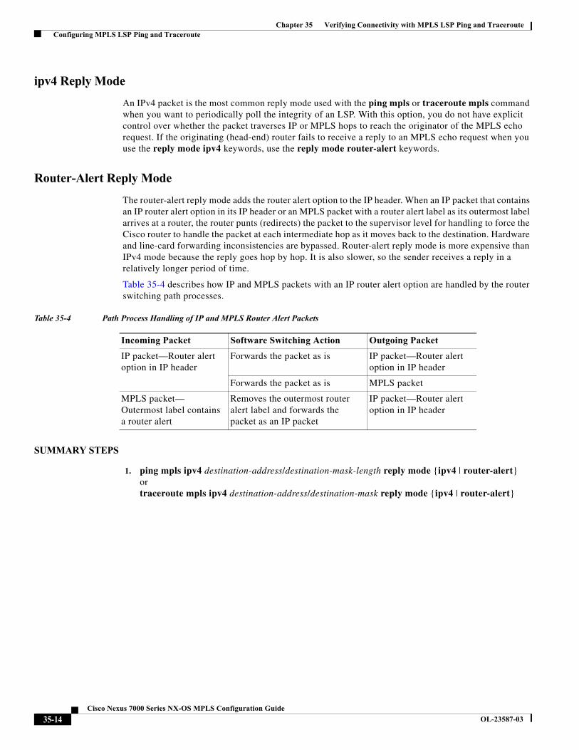
The router-alert reply mode adds the router alert option to the IP header. When an IP packet that contains an IP router alert option in its IP header or an MPLS packet with a router alert label as its outermost label arrives at a router, the router punts (redirects) the packet to the supervisor level for handling to force the Cisco router to handle the packet at each intermediate hop as it moves back to the destination. Hardware and line-card forwarding inconsistencies are bypassed. Router-alert reply mode is more expensive than IPv4 mode because the reply goes hop by hop. It is also slower, so the sender receives a reply in a relatively longer period of time.
Table 35-4 describes how IP and MPLS packets with an IP router alert option are handled by the router switching path processes.
SUMMARY STEPS
1. ping mpls ipv4 destination-address/destination-mask-length reply mode {ipv4 | router-alert}or traceroute mpls ipv4 destination-address/destination-mask reply mode {ipv4 | router-alert}
Table 35-4 Path Process Handling of IP and MPLS Router Alert Packets
Incoming Packet Software Switching Action Outgoing Packet
IP packet—Router alert option in IP header
Forwards the packet as is IP packet—Router alert option in IP header
Forwards the packet as is MPLS packet
MPLS packet— Outermost label contains a router alert
Removes the outermost router alert label and forwards the packet as an IP packet
IP packet—Router alert option in IP header
35-14Cisco Nexus 7000 Series NX-OS MPLS Configuration Guide
OL-23587-03
Chapter 35 Verifying Connectivity with MPLS LSP Ping and Traceroute Configuring MPLS LSP Ping and Traceroute
DETAILED STEPS
Preventing Loops When Using MPLS LSP Ping and LSP Traceroute Command Options
The interaction of the MPLS Embedded Management—LSP Ping for LDP feature options can cause loops. See the following topics for a description of the loops you may encounter with the ping mpls and traceroute mpls commands:
• Using MPLS LSP Ping to Discover Possible Loops, page 35-15
• Using MPLS LSP Traceroute to Discover Possible Loops, page 35-16
Using MPLS LSP Ping to Discover Possible Loops
With the MPLS LSP Ping feature, loops can occur if you use the UDP destination address range, repeat option, or sweep option.
SUMMARY STEPS
1. ping mpls ipv4 destination-address/destination-mask [destination address-start address-end increment] [repeat count] [sweep minimum maximum size-increment]
Command Purpose
Step 1 ping mpls ipv4 destination-address/destination-mask-length reply mode {ipv4 | router-alert}
or
traceroute mpls ipv4 destination-address/destination-mask reply mode {ipv4 | router-alert}
Example: switch# ping mpls ipv4 10.131.191.252/32 reply mode ipv4
or
Example: switch# traceroute mpls ipv4 10.131.191.252/32 reply mode router-alert
Checks MPLS LSP connectivity.
or
Discovers MPLS LSP routes that packets actually take when traveling to their destinations.
Note To specify the reply mode, you must enter the reply mode keyword with the ipv4 or router-alert keyword.
35-15Cisco Nexus 7000 Series NX-OS MPLS Configuration Guide
OL-23587-03
Chapter 35 Verifying Connectivity with MPLS LSP Ping and Traceroute Configuring MPLS LSP Ping and Traceroute
DETAILED STEPS
Using MPLS LSP Traceroute to Discover Possible Loops
With the MPLS LSP Traceroute feature, loops can occur if you use the UDP destination address range option and the Time-to-Live (TTL) option.
By default, the maximum TTL is set to 30. Therefore, the traceroute output might contain 30 lines if the target of the traceroute is not reached, which can happen when an LSP problem exists. If an LSP problem occurs, there might be duplicate entries. The router address of the last point that the trace reaches is repeated until the output is 30 lines. You can ignore the duplicate entries.
SUMMARY STEPS
1. traceroute mpls ipv4 destination-address/destination-mask [destination address-start address-end address-increment] [ttl maximum-time-to-live]
DETAILED STEPS
Detecting LSP Breaks
If there is a problem forwarding MPLS packets in your network, you can determine where the LSP breaks are. This section describes the maximum transmission unit (MTU) discovery in an LSP.
Untagged output interfaces at a penultimate hop do not impact the forwarding of IP packets through an LSP because the forwarding decision is made at the penultimate hop by using an incoming label. However, untagged output interfaces cause MPLS VPN traffic to be dropped at the penultimate hop.
During an MPLS LSP ping, MPLS echo request packets are sent with the IP packet attribute set to the Don’t Fragment (DF) bit in the IP header of the packet. This process allows you to use the MPLS echo request to test for the MTU that can be supported for the packet through LSP without fragmentation.
Command Purpose
Step 1 ping mpls ipv4 destination-address/destination-mask [destination address-start address-end increment] [repeat count] [sweep minimum maximum size-increment]
Example:switch# ping mpls ipv4 10.131.159.251/32 destination 127.0.0.1 127.0.0.2 1 repeat 2 sweep 1450 1475 25
Checks MPLS LSP connectivity.
Command Purpose
Step 1 traceroute mpls ipv4 destination-address/destination-mask [destination address-start address-end address increment] [ttl maximum-time-to-live]
Example:switch# traceroute mpls ipv4 10.131.159.251/32 destination 127.0.0.1 127.0.0.3 1 ttl 5
Discovers MPLS LSP routes that packets take when traveling to their destinations. The example shows how a loop can occur.
35-16Cisco Nexus 7000 Series NX-OS MPLS Configuration Guide
OL-23587-03
Chapter 35 Verifying Connectivity with MPLS LSP Ping and Traceroute Configuring MPLS LSP Ping and Traceroute
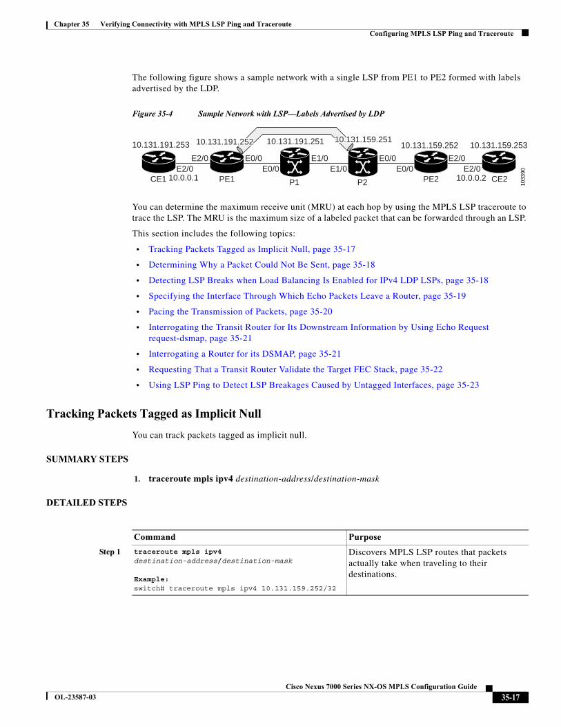
The following figure shows a sample network with a single LSP from PE1 to PE2 formed with labels advertised by the LDP.
Figure 35-4 Sample Network with LSP—Labels Advertised by LDP
You can determine the maximum receive unit (MRU) at each hop by using the MPLS LSP traceroute to trace the LSP. The MRU is the maximum size of a labeled packet that can be forwarded through an LSP.
This section includes the following topics:
• Tracking Packets Tagged as Implicit Null, page 35-17
• Determining Why a Packet Could Not Be Sent, page 35-18
• Detecting LSP Breaks when Load Balancing Is Enabled for IPv4 LDP LSPs, page 35-18
• Specifying the Interface Through Which Echo Packets Leave a Router, page 35-19
• Pacing the Transmission of Packets, page 35-20
• Interrogating the Transit Router for Its Downstream Information by Using Echo Request request-dsmap, page 35-21
• Interrogating a Router for its DSMAP, page 35-21
• Requesting That a Transit Router Validate the Target FEC Stack, page 35-22
• Using LSP Ping to Detect LSP Breakages Caused by Untagged Interfaces, page 35-23
Tracking Packets Tagged as Implicit Null
You can track packets tagged as implicit null.
SUMMARY STEPS
1. traceroute mpls ipv4 destination-address/destination-mask
DETAILED STEPS
1033
90
P1
10.131.191.251
E2/0E2/0 E2/0
E2/0E1/0E1/0E0/0 E0/0
E0/0E0/0
P2CE1
10.131.191.253
PE1 PE2 CE2
10.131.159.25310.131.159.252
10.0.0.1 10.0.0.2
10.131.159.25110.131.159.25110.131.159.25110.131.191.25210.131.191.25210.131.191.252
Command Purpose
Step 1 traceroute mpls ipv4 destination-address/destination-mask
Example: switch# traceroute mpls ipv4 10.131.159.252/32
Discovers MPLS LSP routes that packets actually take when traveling to their destinations.
35-17Cisco Nexus 7000 Series NX-OS MPLS Configuration Guide
OL-23587-03
Chapter 35 Verifying Connectivity with MPLS LSP Ping and Traceroute Configuring MPLS LSP Ping and Traceroute
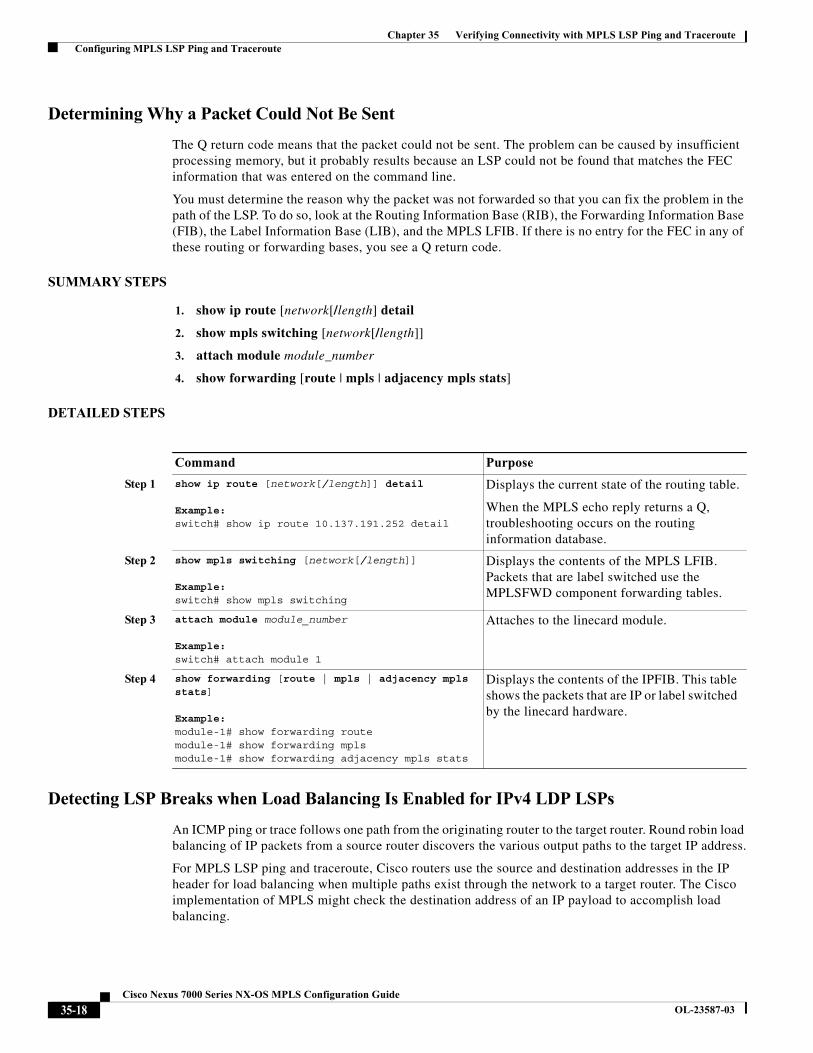
Determining Why a Packet Could Not Be Sent
The Q return code means that the packet could not be sent. The problem can be caused by insufficient processing memory, but it probably results because an LSP could not be found that matches the FEC information that was entered on the command line.
You must determine the reason why the packet was not forwarded so that you can fix the problem in the path of the LSP. To do so, look at the Routing Information Base (RIB), the Forwarding Information Base (FIB), the Label Information Base (LIB), and the MPLS LFIB. If there is no entry for the FEC in any of these routing or forwarding bases, you see a Q return code.
SUMMARY STEPS
1. show ip route [network[/length] detail
2. show mpls switching [network[/length]]
3. attach module module_number
4. show forwarding [route | mpls | adjacency mpls stats]
DETAILED STEPS
Detecting LSP Breaks when Load Balancing Is Enabled for IPv4 LDP LSPs
An ICMP ping or trace follows one path from the originating router to the target router. Round robin load balancing of IP packets from a source router discovers the various output paths to the target IP address.
For MPLS LSP ping and traceroute, Cisco routers use the source and destination addresses in the IP header for load balancing when multiple paths exist through the network to a target router. The Cisco implementation of MPLS might check the destination address of an IP payload to accomplish load balancing.
Command Purpose
Step 1 show ip route [network[/length]] detail
Example: switch# show ip route 10.137.191.252 detail
Displays the current state of the routing table.
When the MPLS echo reply returns a Q, troubleshooting occurs on the routing information database.
Step 2 show mpls switching [network[/length]]
Example: switch# show mpls switching
Displays the contents of the MPLS LFIB. Packets that are label switched use the MPLSFWD component forwarding tables.
Step 3 attach module module_number
Example: switch# attach module 1
Attaches to the linecard module.
Step 4 show forwarding [route | mpls | adjacency mpls stats]
Example: module-1# show forwarding route module-1# show forwarding mpls module-1# show forwarding adjacency mpls stats
Displays the contents of the IPFIB. This table shows the packets that are IP or label switched by the linecard hardware.
35-18Cisco Nexus 7000 Series NX-OS MPLS Configuration Guide
OL-23587-03
Chapter 35 Verifying Connectivity with MPLS LSP Ping and Traceroute Configuring MPLS LSP Ping and Traceroute
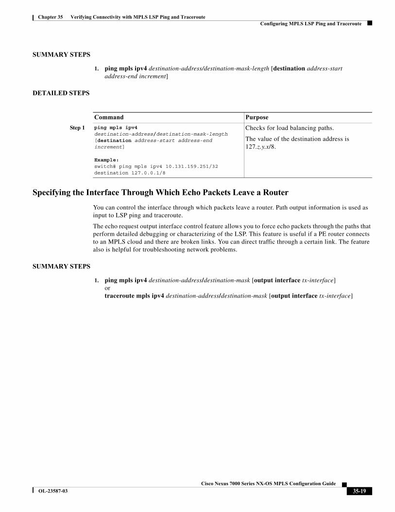
SUMMARY STEPS
1. ping mpls ipv4 destination-address/destination-mask-length [destination address-start address-end increment]
DETAILED STEPS
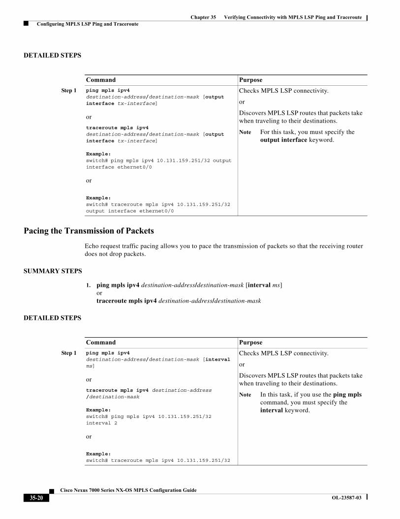
Specifying the Interface Through Which Echo Packets Leave a Router
You can control the interface through which packets leave a router. Path output information is used as input to LSP ping and traceroute.
The echo request output interface control feature allows you to force echo packets through the paths that perform detailed debugging or characterizing of the LSP. This feature is useful if a PE router connects to an MPLS cloud and there are broken links. You can direct traffic through a certain link. The feature also is helpful for troubleshooting network problems.
SUMMARY STEPS
1. ping mpls ipv4 destination-address/destination-mask [output interface tx-interface]ortraceroute mpls ipv4 destination-address/destination-mask [output interface tx-interface]
Command Purpose
Step 1 ping mpls ipv4 destination-address/destination-mask-length [destination address-start address-end increment]
Example: switch# ping mpls ipv4 10.131.159.251/32 destination 127.0.0.1/8
Checks for load balancing paths.
The value of the destination address is 127.z.y.x/8.
35-19Cisco Nexus 7000 Series NX-OS MPLS Configuration Guide
OL-23587-03
Chapter 35 Verifying Connectivity with MPLS LSP Ping and Traceroute Configuring MPLS LSP Ping and Traceroute
DETAILED STEPS
Pacing the Transmission of Packets
Echo request traffic pacing allows you to pace the transmission of packets so that the receiving router does not drop packets.
SUMMARY STEPS
1. ping mpls ipv4 destination-address/destination-mask [interval ms] or traceroute mpls ipv4 destination-address/destination-mask
DETAILED STEPS
Command Purpose
Step 1 ping mpls ipv4 destination-address/destination-mask [output interface tx-interface]
or
traceroute mpls ipv4 destination-address/destination-mask [output interface tx-interface]
Example: switch# ping mpls ipv4 10.131.159.251/32 output interface ethernet0/0
or
Example: switch# traceroute mpls ipv4 10.131.159.251/32 output interface ethernet0/0
Checks MPLS LSP connectivity.
or
Discovers MPLS LSP routes that packets take when traveling to their destinations.
Note For this task, you must specify the output interface keyword.
Command Purpose
Step 1 ping mpls ipv4 destination-address/destination-mask [interval ms]
or
traceroute mpls ipv4 destination-address /destination-mask
Example: switch# ping mpls ipv4 10.131.159.251/32 interval 2
or
Example: switch# traceroute mpls ipv4 10.131.159.251/32
Checks MPLS LSP connectivity.
or
Discovers MPLS LSP routes that packets take when traveling to their destinations.
Note In this task, if you use the ping mpls command, you must specify the interval keyword.
35-20Cisco Nexus 7000 Series NX-OS MPLS Configuration Guide
OL-23587-03
Chapter 35 Verifying Connectivity with MPLS LSP Ping and Traceroute Configuring MPLS LSP Ping and Traceroute
Interrogating the Transit Router for Its Downstream Information by Using Echo Request request-dsmap
When you use the echo request request-dsmap capability troubleshooting feature with the TTL flag, you can selectively interrogate a transit router. If there is a failure, you do not have to enter an lsp traceroute command for each previous failure; you can focus just on the failed hop.
A request-dsmap flag in the downstream mapping flags field and procedures that specify how to trace noncompliant routers allow you to arbitrarily TTL expire MPLS echo request packets with a wildcard downstream map (DSMAP).
Echo request DSMAPs received without labels indicate that the sender did not have any DSMAPs to validate. If the downstream router ID field of the DSMAP TLV in an echo request is set to the ALLROUTERs address (224.0.0.2) and there are no labels, the source router can arbitrarily query a transit router for its DSMAP information.
Use the ping mpls command to allow an MPLS echo request to be TTL-expired at a transit router with a wildcard DSMAP for the explicit purpose of troubleshooting and querying the downstream router for its DSMAPs. The default is that the DSMAP has an IPv4 bitmap hashkey. You also can select hashkey 0 (none). The ping mpls command allows the source router to selectively TTL expire an echo request at a transit router to interrogate the transit router for its downstream information. The ability to select a multipath (hashkey) type allows the transmitting router to interrogate a transit router for load-balancing information as is done with multipath LSP traceroute but without having to interrogate all subsequent nodes traversed between the source router and the router on which each echo request TTL expires. You should use an echo request with the TTL setting because if an echo request arrives at the egress of the LSP without an echo request, the responding routers never return DSMAPs.
SUMMARY STEPS
1. ping mpls ipv4 destination-address/destination-mask [dsmap [hashkey {none | ipv4 bitmap bitmap-size}]]
DETAILED STEPS
Interrogating a Router for its DSMAP
The router can interrogate the software or hardware forwarding layer for the depth limit that needs to be returned in the DSMAP TLV. If forwarding does not provide a value, the default is 255.
To determine the depth limit, specify the dsmap and ttl keywords in the ping mpls command. The transit router is interrogated for its DSMAP. The depth limit is returned with the echo reply DSMAP. A value of 0 means that the IP header is used for load balancing. Another value indicates that the IP header load balances up to the specified number of labels.
Command Purpose
Step 1 ping mpls ipv4 destination-address/destination-mask [dsmap [hashkey {none | ipv4 bitmap bitmap-size}]]
Example: switch# ping mpls ipv4 10.161.251/32 dsmap hashkey ipv4 bitmap 16
Checks MPLS LSP connectivity.
Note In this task, you must specify the dsmap and hashkey keywords.
35-21Cisco Nexus 7000 Series NX-OS MPLS Configuration Guide
OL-23587-03
Chapter 35 Verifying Connectivity with MPLS LSP Ping and Traceroute Configuring MPLS LSP Ping and Traceroute
SUMMARY STEPS
1. ping mpls ipv4 destination-address/destination-mask ttl time-to-live dsmap
DETAILED STEPS
Requesting That a Transit Router Validate the Target FEC Stack
An MPLS echo request tests a particular LSP. The LSP to be tested is identified by the FEC stack.
To request that a transit router validate the target FEC stack, set the V flag from the source router by entering the flags fec keyword in the ping mpls and traceroute mpls commands. The default is that echo request packets are sent with the V flag set to 0.
SUMMARY STEPS
1. ping mpls ipv4 destination-address/destination-mask flags fec ortraceroute mpls ipv4 destination-address/destination-mask flags fec
DETAILED STEPS
Command Purpose
Step 1 ping mpls ipv4 destination-address/destination-mask ttl time-to-live dsmap
Example:switch# ping mpls ipv4 10.131.159.252/32 ttl 1 dsmap
Checks MPLS LSP connectivity.
Note You must specify the ttl and dsmap keywords.
Command Purpose
Step 1 ping mpls ipv4 destination-address/destination-mask flags fec
or
traceroute mpls ipv4 destination-address/destination-mask flags fec
Example:switch# ping mpls ipv4 10.131.159.252/32 flags fec
or
Example:switch# traceroute mpls ipv4 10.131.159.252/32 flags fec
Checks MPLS LSP connectivity.
or
Discovers MPLS LSP routes that packets actually take when traveling to their destinations.
Note You must enter the flags fec keyword.
35-22Cisco Nexus 7000 Series NX-OS MPLS Configuration Guide
OL-23587-03
Chapter 35 Verifying Connectivity with MPLS LSP Ping and Traceroute Troubleshooting Examples Using MPLS LSP Ping and Traceroute
Using LSP Ping to Detect LSP Breakages Caused by Untagged Interfaces
For MPLS LSP ping and traceroute of LSPs carrying IPv4 FECs, you can force an explicit null label to be added to the MPLS label stack even though the label was unsolicited. This process allows LSP ping to detect LSP breakages caused by untagged interfaces. LSP ping does not report that an LSP is operational when it is unable to send MPLS traffic.
An explicit null label is added to an MPLS label stack if MPLS echo request packets are forwarded from untagged interfaces that are directly connected to the destination of the LSP ping or if the IP TTL value for the MPLS echo request packets is set to 1.
When you enter the lsp ping command, you are testing the LSP’s ability to carry IP traffic. Failures at untagged output interfaces at the penultimate hop are not detected. Explicit-null shimming allows you to test an LSP’s ability to carry MPLS traffic.
You can enable LSP ping to detect LSP breakages caused by untagged interfaces by specifying the force-explicit-null keyword in the ping mpls or traceroute mpls commands.
SUMMARY STEPS
1. ping mpls ipv4 destination-address/destination-mask force-explicit-null ortraceroute mpls ipv4 destination-address/destination-mask force-explicit-null
DETAILED STEP
Troubleshooting Examples Using MPLS LSP Ping and Traceroute
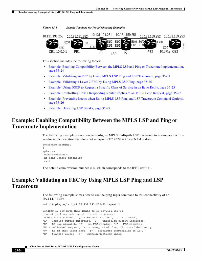
Examples for the MPLS LSP ping and traceroute for LDP and TE are based on the sample topology shown in the figure below.
Command Purpose
Step 1 ping mpls ipv4 destination-address/destination-mask force-explicit-null
or
traceroute mpls ipv4 destination-address/destination-mask force-explicit-null
Example: switch# ping mpls ipv4 10.131.191.252/32 force-explicit-null
or
Example: switch# traceroute mpls ipv4 10.131.191.252/32 force-explicit-null
Checks MPLS LSP connectivity.
or
Discovers MPLS LSP routes that packets actually take when traveling to their destinations.
Note You must enter the force-explicit-null keyword.
35-23Cisco Nexus 7000 Series NX-OS MPLS Configuration Guide
OL-23587-03
Chapter 35 Verifying Connectivity with MPLS LSP Ping and Traceroute Troubleshooting Examples Using MPLS LSP Ping and Traceroute
Figure 35-5 Sample Topology for Troubleshooting Examples
This section includes the following topics:
• Example: Enabling Compatibility Between the MPLS LSP and Ping or Traceroute Implementation, page 35-24
• Example: Validating an FEC by Using MPLS LSP Ping and LSP Traceroute, page 35-24
• Example: Validating a Layer 2 FEC by Using MPLS LSP Ping, page 35-25
• Example: Using DSCP to Request a Specific Class of Service in an Echo Reply, page 35-25
• Example: Controlling How a Responding Router Replies to an MPLS Echo Request, page 35-25
• Example: Preventing Loops when Using MPLS LSP Ping and LSP Traceroute Command Options, page 35-26
• Example: Detecting LSP Breaks, page 35-29
Example: Enabling Compatibility Between the MPLS LSP and Ping or Traceroute Implementation
The following example shows how to configure MPLS multipath LSP traceroute to interoperate with a vendor implementation that does not interpret RFC 4379 as Cisco NX-OS does:
configure terminal!mpls oamecho revision 4no echo vendor-extensionexit
The default echo revision number is 4, which corresponds to the IEFT draft 11.
Example: Validating an FEC by Using MPLS LSP Ping and LSP Traceroute
The following example shows how to use the ping mpls command to test connectivity of an IPv4 LDP LSP:
switch# ping mpls ipv4 10.137.191.252/32 repeat 1
Sending 1, 100-byte MPLS Echos to 10.137.191.252/32,timeout is 2 seconds, send interval is 0 msec:Codes: '!' - success, 'Q' - request not sent, '.' - timeout,'L' - labeled output interface, 'B' - unlabeled output interface,'D' - DS Map mismatch, 'F' - no FEC mapping, 'f' - FEC mismatch,'M' - malformed request, 'm' - unsupported tlvs, 'N' - no label entry,'P' - no rx intf label prot, 'p' - premature termination of LSP,'R' - transit router, 'I' - unknown upstream index,
P1
10.131.191.251
E2/0
E2/0 E2/0
E2/0E1/1E1/1
E1/0 E1/0E0/0 E0/0 E0/0E0/1E0/1E0/0
P2LSP
10.131.159.251
10
33
92
CE1
10.131.191.253
PE1 PE2 CE2
10.131.159.25310.131.191.252 10.131.159.252
10.0.0.1 10.0.0.2
35-24Cisco Nexus 7000 Series NX-OS MPLS Configuration Guide
OL-23587-03
Chapter 35 Verifying Connectivity with MPLS LSP Ping and Traceroute Troubleshooting Examples Using MPLS LSP Ping and Traceroute
'X' - unknown return code, 'x' - return code 0
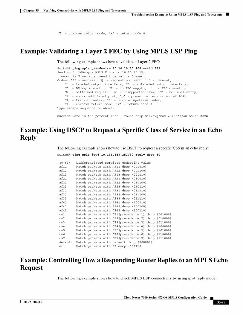
Example: Validating a Layer 2 FEC by Using MPLS LSP Ping
The following example shows how to validate a Layer 2 FEC:
Switch# ping mpls pseudowire 10.10.10.15 108 vc-id 333Sending 5, 100-byte MPLS Echos to 10.10.10.15,timeout is 2 seconds, send interval is 0 msec:Codes: '!' - success, 'Q' - request not sent, '.' - timeout,
'L' - labeled output interface, 'B' - unlabeled output interface,'D' - DS Map mismatch, 'F' - no FEC mapping, 'f' - FEC mismatch,'M' - malformed request, 'm' - unsupported tlvs, 'N' - no label entry,'P' - no rx intf label prot, 'p' - premature termination of LSP,'R' - transit router, 'I' - unknown upstream index,'X' - unknown return code, 'x' - return code 0
Type escape sequence to abort.!!!!!Success rate is 100 percent (5/5), round-trip min/avg/max = 28/32/40 ms PE-802#
Example: Using DSCP to Request a Specific Class of Service in an Echo Reply
The following example shows how to use DSCP to request a specific CoS in an echo reply:
switch# ping mpls ipv4 10.131.159.252/32 reply dscp 50
<0-63> Differentiated services codepoint value af11 Match packets with AF11 dscp (001010) af12 Match packets with AF12 dscp (001100) af13 Match packets with AF13 dscp (001110) af21 Match packets with AF21 dscp (010010) af22 Match packets with AF22 dscp (010100) af23 Match packets with AF23 dscp (010110) af31 Match packets with AF31 dscp (011010) af32 Match packets with AF32 dscp (011100) af33 Match packets with AF33 dscp (011110) af41 Match packets with AF41 dscp (100010) af42 Match packets with AF42 dscp (100100) af43 Match packets with AF43 dscp (100110) cs1 Match packets with CS1(precedence 1) dscp (001000) cs2 Match packets with CS2(precedence 2) dscp (010000) cs3 Match packets with CS3(precedence 3) dscp (011000) cs4 Match packets with CS4(precedence 4) dscp (100000) cs5 Match packets with CS5(precedence 5) dscp (101000) cs6 Match packets with CS6(precedence 6) dscp (110000) cs7 Match packets with CS7(precedence 7) dscp (111000) default Match packets with default dscp (000000) ef Match packets with EF dscp (101110)
Example: Controlling How a Responding Router Replies to an MPLS Echo Request
The following example shows how to check MPLS LSP connectivity by using ipv4 reply mode:
35-25Cisco Nexus 7000 Series NX-OS MPLS Configuration Guide
OL-23587-03
Chapter 35 Verifying Connectivity with MPLS LSP Ping and Traceroute Troubleshooting Examples Using MPLS LSP Ping and Traceroute
switch# ping mpls ipv4 10.131.191.252/32 reply mode ipv4
Example: Preventing Loops when Using MPLS LSP Ping and LSP Traceroute Command Options
This section contains the following topics:
• Example: Possible Loops with MPLS LSP Ping, page 35-26
• Example: Possible Loop with MPLS LSP Traceroute, page 35-27
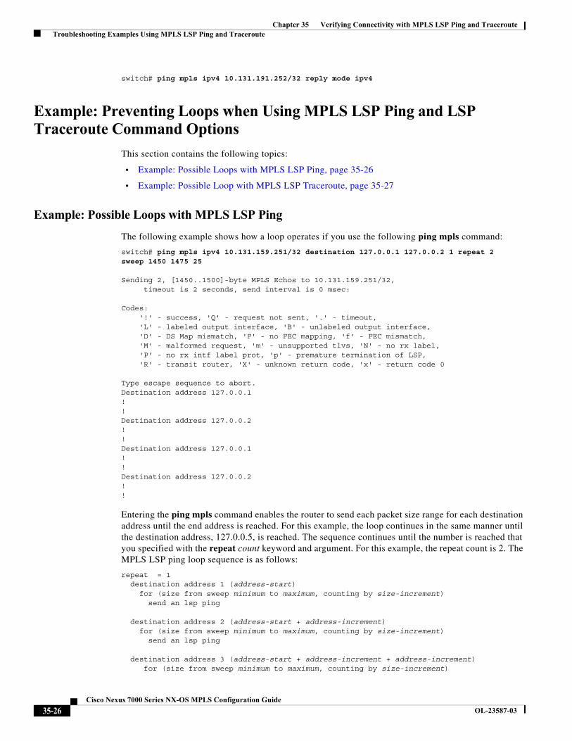
Example: Possible Loops with MPLS LSP Ping
The following example shows how a loop operates if you use the following ping mpls command:
switch# ping mpls ipv4 10.131.159.251/32 destination 127.0.0.1 127.0.0.2 1 repeat 2sweep 1450 1475 25
Sending 2, [1450..1500]-byte MPLS Echos to 10.131.159.251/32,timeout is 2 seconds, send interval is 0 msec:
Codes:'!' - success, 'Q' - request not sent, '.' - timeout,'L' - labeled output interface, 'B' - unlabeled output interface,'D' - DS Map mismatch, 'F' - no FEC mapping, 'f' - FEC mismatch,'M' - malformed request, 'm' - unsupported tlvs, 'N' - no rx label,'P' - no rx intf label prot, 'p' - premature termination of LSP,'R' - transit router, 'X' - unknown return code, 'x' - return code 0
Type escape sequence to abort.Destination address 127.0.0.1!!Destination address 127.0.0.2!!Destination address 127.0.0.1!!Destination address 127.0.0.2!!
Entering the ping mpls command enables the router to send each packet size range for each destination address until the end address is reached. For this example, the loop continues in the same manner until the destination address, 127.0.0.5, is reached. The sequence continues until the number is reached that you specified with the repeat count keyword and argument. For this example, the repeat count is 2. The MPLS LSP ping loop sequence is as follows:
repeat = 1destination address 1 (address-start)
for (size from sweep minimum to maximum, counting by size-increment)send an lsp ping
destination address 2 (address-start + address-increment)for (size from sweep minimum to maximum, counting by size-increment)
send an lsp ping
destination address 3 (address-start + address-increment + address-increment)for (size from sweep minimum to maximum, counting by size-increment)
35-26Cisco Nexus 7000 Series NX-OS MPLS Configuration Guide
OL-23587-03
Chapter 35 Verifying Connectivity with MPLS LSP Ping and Traceroute Troubleshooting Examples Using MPLS LSP Ping and Traceroute
send an lsp ping...until destination address = address-end
.
.
.until repeat = count 2
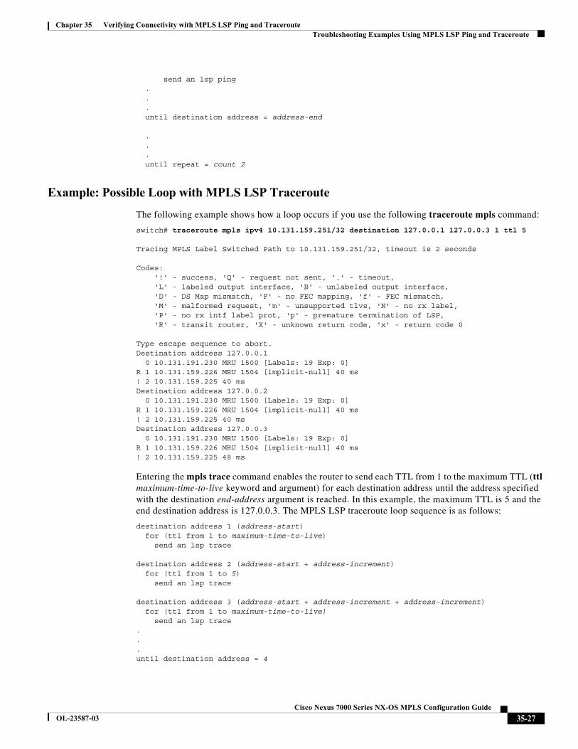
Example: Possible Loop with MPLS LSP Traceroute
The following example shows how a loop occurs if you use the following traceroute mpls command:
switch# traceroute mpls ipv4 10.131.159.251/32 destination 127.0.0.1 127.0.0.3 1 ttl 5
Tracing MPLS Label Switched Path to 10.131.159.251/32, timeout is 2 seconds
Codes:'!' - success, 'Q' - request not sent, '.' - timeout,'L' - labeled output interface, 'B' - unlabeled output interface,'D' - DS Map mismatch, 'F' - no FEC mapping, 'f' - FEC mismatch,'M' - malformed request, 'm' - unsupported tlvs, 'N' - no rx label,'P' - no rx intf label prot, 'p' - premature termination of LSP,'R' - transit router, 'X' - unknown return code, 'x' - return code 0
Type escape sequence to abort.Destination address 127.0.0.1
0 10.131.191.230 MRU 1500 [Labels: 19 Exp: 0]R 1 10.131.159.226 MRU 1504 [implicit-null] 40 ms! 2 10.131.159.225 40 msDestination address 127.0.0.2
0 10.131.191.230 MRU 1500 [Labels: 19 Exp: 0]R 1 10.131.159.226 MRU 1504 [implicit-null] 40 ms! 2 10.131.159.225 40 msDestination address 127.0.0.3
0 10.131.191.230 MRU 1500 [Labels: 19 Exp: 0]R 1 10.131.159.226 MRU 1504 [implicit-null] 40 ms! 2 10.131.159.225 48 ms
Entering the mpls trace command enables the router to send each TTL from 1 to the maximum TTL (ttl maximum-time-to-live keyword and argument) for each destination address until the address specified with the destination end-address argument is reached. In this example, the maximum TTL is 5 and the end destination address is 127.0.0.3. The MPLS LSP traceroute loop sequence is as follows:
destination address 1 (address-start)for (ttl from 1 to maximum-time-to-live)
send an lsp trace
destination address 2 (address-start + address-increment)for (ttl from 1 to 5)
send an lsp trace
destination address 3 (address-start + address-increment + address-increment)for (ttl from 1 to maximum-time-to-live)
send an lsp trace...until destination address = 4
35-27Cisco Nexus 7000 Series NX-OS MPLS Configuration Guide
OL-23587-03
Chapter 35 Verifying Connectivity with MPLS LSP Ping and Traceroute Troubleshooting Examples Using MPLS LSP Ping and Traceroute
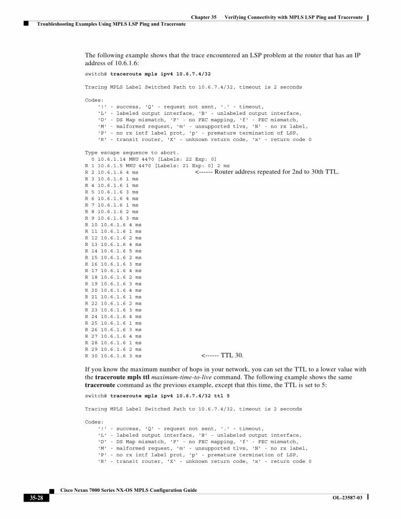
The following example shows that the trace encountered an LSP problem at the router that has an IP address of 10.6.1.6:
switch# traceroute mpls ipv4 10.6.7.4/32
Tracing MPLS Label Switched Path to 10.6.7.4/32, timeout is 2 seconds
Codes:'!' - success, 'Q' - request not sent, '.' - timeout,'L' - labeled output interface, 'B' - unlabeled output interface,'D' - DS Map mismatch, 'F' - no FEC mapping, 'f' - FEC mismatch,'M' - malformed request, 'm' - unsupported tlvs, 'N' - no rx label,'P' - no rx intf label prot, 'p' - premature termination of LSP,'R' - transit router, 'X' - unknown return code, 'x' - return code 0
Type escape sequence to abort.0 10.6.1.14 MRU 4470 [Labels: 22 Exp: 0]
R 1 10.6.1.5 MRU 4470 [Labels: 21 Exp: 0] 2 msR 2 10.6.1.6 4 ms <------ Router address repeated for 2nd to 30th TTL.R 3 10.6.1.6 1 msR 4 10.6.1.6 1 msR 5 10.6.1.6 3 msR 6 10.6.1.6 4 msR 7 10.6.1.6 1 msR 8 10.6.1.6 2 msR 9 10.6.1.6 3 msR 10 10.6.1.6 4 msR 11 10.6.1.6 1 msR 12 10.6.1.6 2 msR 13 10.6.1.6 4 msR 14 10.6.1.6 5 msR 15 10.6.1.6 2 msR 16 10.6.1.6 3 msR 17 10.6.1.6 4 msR 18 10.6.1.6 2 msR 19 10.6.1.6 3 msR 20 10.6.1.6 4 msR 21 10.6.1.6 1 msR 22 10.6.1.6 2 msR 23 10.6.1.6 3 msR 24 10.6.1.6 4 msR 25 10.6.1.6 1 msR 26 10.6.1.6 3 msR 27 10.6.1.6 4 msR 28 10.6.1.6 1 msR 29 10.6.1.6 2 msR 30 10.6.1.6 3 ms <------ TTL 30.
If you know the maximum number of hops in your network, you can set the TTL to a lower value with the traceroute mpls ttl maximum-time-to-live command. The following example shows the same traceroute command as the previous example, except that this time, the TTL is set to 5:
switch# traceroute mpls ipv4 10.6.7.4/32 ttl 5
Tracing MPLS Label Switched Path to 10.6.7.4/32, timeout is 2 seconds
Codes:'!' - success, 'Q' - request not sent, '.' - timeout,'L' - labeled output interface, 'B' - unlabeled output interface,'D' - DS Map mismatch, 'F' - no FEC mapping, 'f' - FEC mismatch,'M' - malformed request, 'm' - unsupported tlvs, 'N' - no rx label,'P' - no rx intf label prot, 'p' - premature termination of LSP,'R' - transit router, 'X' - unknown return code, 'x' - return code 0
35-28Cisco Nexus 7000 Series NX-OS MPLS Configuration Guide
OL-23587-03
Chapter 35 Verifying Connectivity with MPLS LSP Ping and Traceroute Troubleshooting Examples Using MPLS LSP Ping and Traceroute
Type escape sequence to abort.0 10.6.1.14 MRU 4470 [Labels: 22 Exp: 0]
R 1 10.6.1.5 MRU 4474 [No Label] 3 msR 2 10.6.1.6 4 ms <------ Router address repeated for 2nd to 5th TTL.R 3 10.6.1.6 1 msR 4 10.6.1.6 3 msR 5 10.6.1.6 4 ms
Example: Detecting LSP Breaks
This section includes the following topics:
• Example: Troubleshooting with LSP Ping or Traceroute, page 35-29
• Example: MTU Discovery in an LSP, page 35-33
• Example: Tracking Packets Tagged as Implicit Null, page 35-35
• Example: Tracking Untagged Packets, page 35-35
• Example: Determining Why a Packet Could Not Be Sent, page 35-36
• Example: Detecting LSP Breaks when Load Balancing Is Enabled for IPv4 LSPs, page 35-37
• Example: Specifying the Interface Through Which Echo Packets Leave a Router, page 35-39
• Example: Pacing the Transmission of Packets, page 35-40
• Example: Interrogating the Transit Router for Its Downstream Information, page 35-40
• Example: Interrogating a Router for its DSMAP, page 35-42
• Example: Requesting that a Transit Router Validate the Target FEC Stack, page 35-42
• Example: Enabling LSP Ping to Detect LSP Breakages Caused by Untagged Interfaces, page 35-43
Example: Troubleshooting with LSP Ping or Traceroute
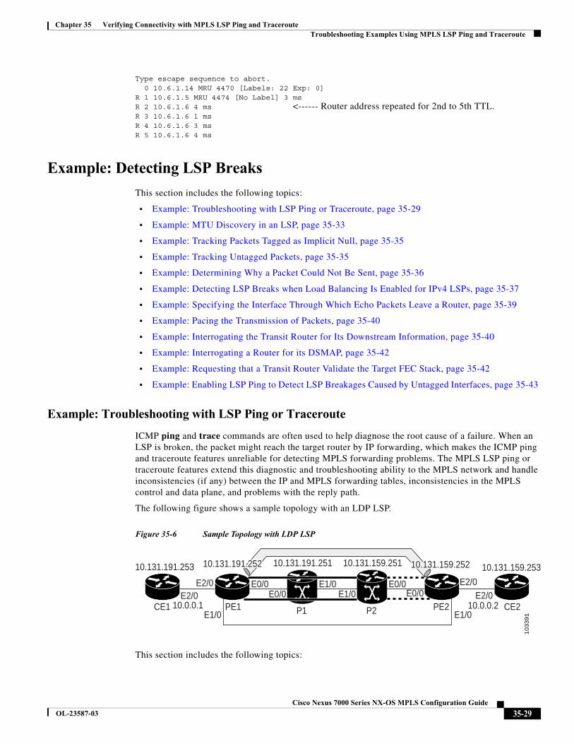
ICMP ping and trace commands are often used to help diagnose the root cause of a failure. When an LSP is broken, the packet might reach the target router by IP forwarding, which makes the ICMP ping and traceroute features unreliable for detecting MPLS forwarding problems. The MPLS LSP ping or traceroute features extend this diagnostic and troubleshooting ability to the MPLS network and handle inconsistencies (if any) between the IP and MPLS forwarding tables, inconsistencies in the MPLS control and data plane, and problems with the reply path.
The following figure shows a sample topology with an LDP LSP.
Figure 35-6 Sample Topology with LDP LSP
This section includes the following topics:
P1
10.131.191.251
E2/0E2/0 E2/0
E2/0E1/0E1/0E0/0 E0/0
E0/0E0/0
P2
10.131.159.251
10
33
91
CE1
10.131.191.253
PE1E1/0 E1/0
PE2 CE2
10.131.159.253
10.0.0.1 10.0.0.2
10.131.191.25210.131.191.25210.131.191.252 10.131.159.25210.131.159.25210.131.159.252
35-29Cisco Nexus 7000 Series NX-OS MPLS Configuration Guide
OL-23587-03
Chapter 35 Verifying Connectivity with MPLS LSP Ping and Traceroute Troubleshooting Examples Using MPLS LSP Ping and Traceroute
• Verifying that the LSP Is Configured Correctly, page 35-30
• Discovery of LSP Breaks, page 35-30
Verifying that the LSP Is Configured Correctly
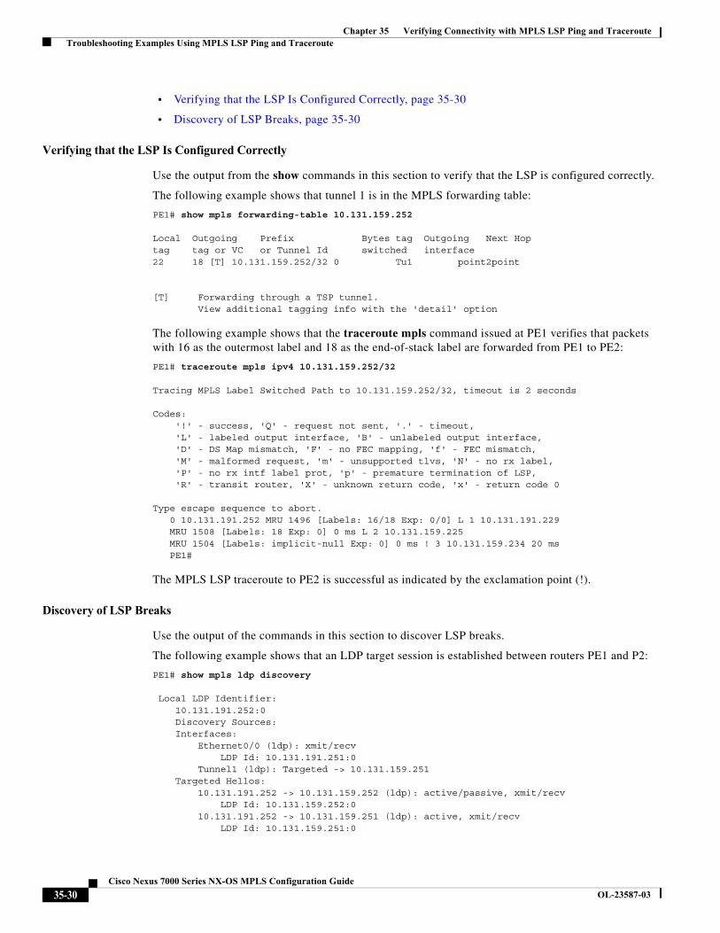
Use the output from the show commands in this section to verify that the LSP is configured correctly.
The following example shows that tunnel 1 is in the MPLS forwarding table:
PE1# show mpls forwarding-table 10.131.159.252
Local Outgoing Prefix Bytes tag Outgoing Next Hoptag tag or VC or Tunnel Id switched interface22 18 [T] 10.131.159.252/32 0 Tu1 point2point
[T] Forwarding through a TSP tunnel.View additional tagging info with the 'detail' option
The following example shows that the traceroute mpls command issued at PE1 verifies that packets with 16 as the outermost label and 18 as the end-of-stack label are forwarded from PE1 to PE2:
PE1# traceroute mpls ipv4 10.131.159.252/32
Tracing MPLS Label Switched Path to 10.131.159.252/32, timeout is 2 seconds
Codes:'!' - success, 'Q' - request not sent, '.' - timeout,'L' - labeled output interface, 'B' - unlabeled output interface,'D' - DS Map mismatch, 'F' - no FEC mapping, 'f' - FEC mismatch,'M' - malformed request, 'm' - unsupported tlvs, 'N' - no rx label,'P' - no rx intf label prot, 'p' - premature termination of LSP,'R' - transit router, 'X' - unknown return code, 'x' - return code 0
Type escape sequence to abort.0 10.131.191.252 MRU 1496 [Labels: 16/18 Exp: 0/0] L 1 10.131.191.229MRU 1508 [Labels: 18 Exp: 0] 0 ms L 2 10.131.159.225 MRU 1504 [Labels: implicit-null Exp: 0] 0 ms ! 3 10.131.159.234 20 ms PE1#
The MPLS LSP traceroute to PE2 is successful as indicated by the exclamation point (!).
Discovery of LSP Breaks
Use the output of the commands in this section to discover LSP breaks.
The following example shows that an LDP target session is established between routers PE1 and P2:
PE1# show mpls ldp discovery
Local LDP Identifier:10.131.191.252:0Discovery Sources:Interfaces:
Ethernet0/0 (ldp): xmit/recvLDP Id: 10.131.191.251:0
Tunnel1 (ldp): Targeted -> 10.131.159.251Targeted Hellos:
10.131.191.252 -> 10.131.159.252 (ldp): active/passive, xmit/recvLDP Id: 10.131.159.252:0
10.131.191.252 -> 10.131.159.251 (ldp): active, xmit/recvLDP Id: 10.131.159.251:0
35-30Cisco Nexus 7000 Series NX-OS MPLS Configuration Guide
OL-23587-03
Chapter 35 Verifying Connectivity with MPLS LSP Ping and Traceroute Troubleshooting Examples Using MPLS LSP Ping and Traceroute
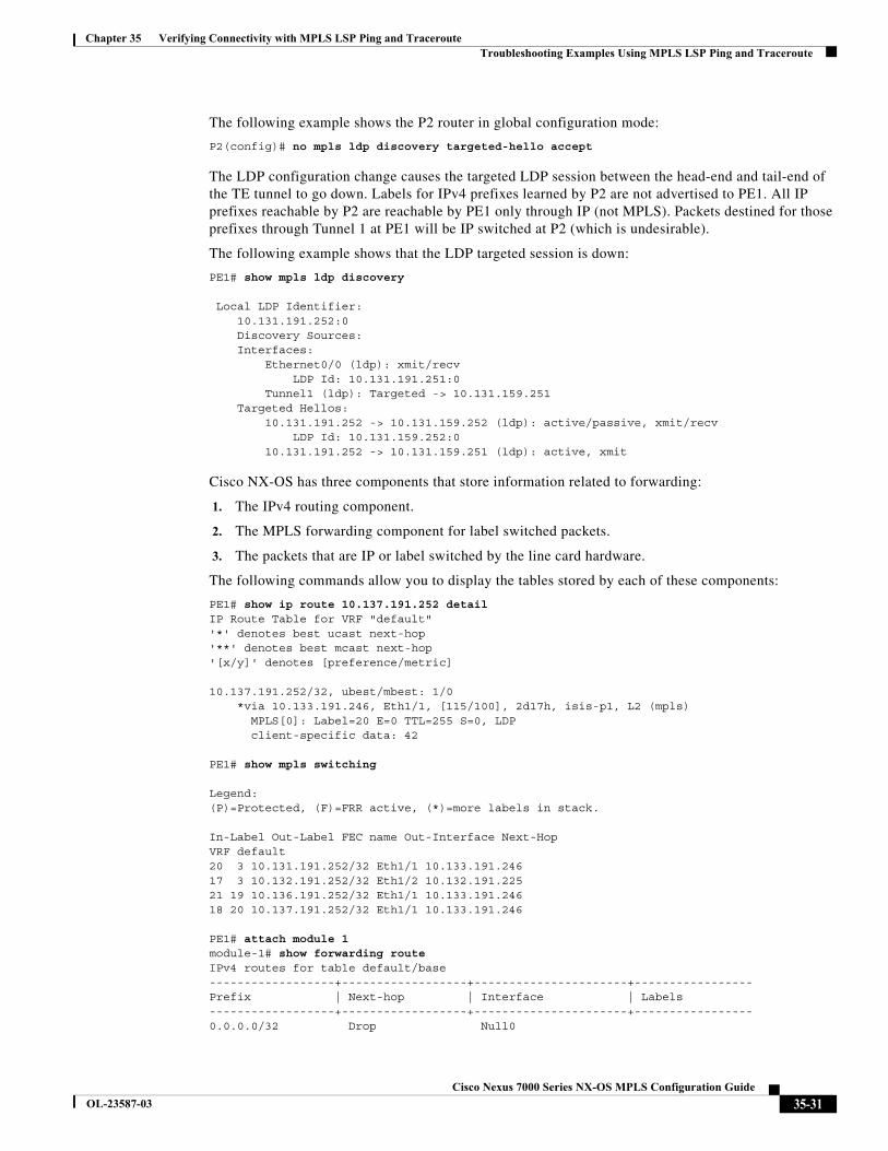
The following example shows the P2 router in global configuration mode:
P2(config)# no mpls ldp discovery targeted-hello accept
The LDP configuration change causes the targeted LDP session between the head-end and tail-end of the TE tunnel to go down. Labels for IPv4 prefixes learned by P2 are not advertised to PE1. All IP prefixes reachable by P2 are reachable by PE1 only through IP (not MPLS). Packets destined for those prefixes through Tunnel 1 at PE1 will be IP switched at P2 (which is undesirable).
The following example shows that the LDP targeted session is down:
PE1# show mpls ldp discovery
Local LDP Identifier:10.131.191.252:0Discovery Sources:Interfaces:
Ethernet0/0 (ldp): xmit/recvLDP Id: 10.131.191.251:0
Tunnel1 (ldp): Targeted -> 10.131.159.251Targeted Hellos:
10.131.191.252 -> 10.131.159.252 (ldp): active/passive, xmit/recvLDP Id: 10.131.159.252:0
10.131.191.252 -> 10.131.159.251 (ldp): active, xmit
Cisco NX-OS has three components that store information related to forwarding:
1. The IPv4 routing component.
2. The MPLS forwarding component for label switched packets.
3. The packets that are IP or label switched by the line card hardware.
The following commands allow you to display the tables stored by each of these components:
PE1# show ip route 10.137.191.252 detailIP Route Table for VRF "default"'*' denotes best ucast next-hop'**' denotes best mcast next-hop'[x/y]' denotes [preference/metric]
10.137.191.252/32, ubest/mbest: 1/0*via 10.133.191.246, Eth1/1, [115/100], 2d17h, isis-p1, L2 (mpls)
MPLS[0]: Label=20 E=0 TTL=255 S=0, LDPclient-specific data: 42
PE1# show mpls switching
Legend:(P)=Protected, (F)=FRR active, (*)=more labels in stack.
In-Label Out-Label FEC name Out-Interface Next-HopVRF default20 3 10.131.191.252/32 Eth1/1 10.133.191.24617 3 10.132.191.252/32 Eth1/2 10.132.191.22521 19 10.136.191.252/32 Eth1/1 10.133.191.24618 20 10.137.191.252/32 Eth1/1 10.133.191.246
PE1# attach module 1module-1# show forwarding routeIPv4 routes for table default/base------------------+------------------+----------------------+-----------------Prefix | Next-hop | Interface | Labels------------------+------------------+----------------------+-----------------0.0.0.0/32 Drop Null0
35-31Cisco Nexus 7000 Series NX-OS MPLS Configuration Guide
OL-23587-03
Chapter 35 Verifying Connectivity with MPLS LSP Ping and Traceroute Troubleshooting Examples Using MPLS LSP Ping and Traceroute
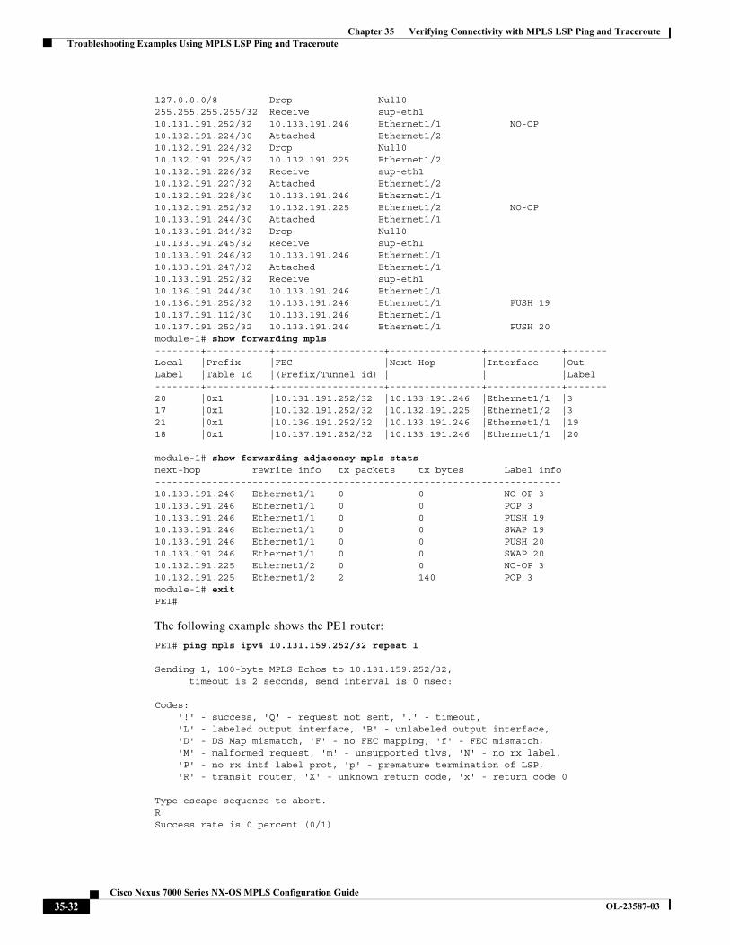
127.0.0.0/8 Drop Null0255.255.255.255/32 Receive sup-eth110.131.191.252/32 10.133.191.246 Ethernet1/1 NO-OP10.132.191.224/30 Attached Ethernet1/210.132.191.224/32 Drop Null010.132.191.225/32 10.132.191.225 Ethernet1/210.132.191.226/32 Receive sup-eth110.132.191.227/32 Attached Ethernet1/210.132.191.228/30 10.133.191.246 Ethernet1/110.132.191.252/32 10.132.191.225 Ethernet1/2 NO-OP10.133.191.244/30 Attached Ethernet1/110.133.191.244/32 Drop Null010.133.191.245/32 Receive sup-eth110.133.191.246/32 10.133.191.246 Ethernet1/110.133.191.247/32 Attached Ethernet1/110.133.191.252/32 Receive sup-eth110.136.191.244/30 10.133.191.246 Ethernet1/110.136.191.252/32 10.133.191.246 Ethernet1/1 PUSH 1910.137.191.112/30 10.133.191.246 Ethernet1/110.137.191.252/32 10.133.191.246 Ethernet1/1 PUSH 20module-1# show forwarding mpls--------+-----------+-------------------+----------------+-------------+-------Local |Prefix |FEC |Next-Hop |Interface |OutLabel |Table Id |(Prefix/Tunnel id) | | |Label--------+-----------+-------------------+----------------+-------------+-------20 |0x1 |10.131.191.252/32 |10.133.191.246 |Ethernet1/1 |317 |0x1 |10.132.191.252/32 |10.132.191.225 |Ethernet1/2 |321 |0x1 |10.136.191.252/32 |10.133.191.246 |Ethernet1/1 |1918 |0x1 |10.137.191.252/32 |10.133.191.246 |Ethernet1/1 |20
module-1# show forwarding adjacency mpls statsnext-hop rewrite info tx packets tx bytes Label info-----------------------------------------------------------------------10.133.191.246 Ethernet1/1 0 0 NO-OP 310.133.191.246 Ethernet1/1 0 0 POP 310.133.191.246 Ethernet1/1 0 0 PUSH 1910.133.191.246 Ethernet1/1 0 0 SWAP 1910.133.191.246 Ethernet1/1 0 0 PUSH 2010.133.191.246 Ethernet1/1 0 0 SWAP 2010.132.191.225 Ethernet1/2 0 0 NO-OP 310.132.191.225 Ethernet1/2 2 140 POP 3module-1# exitPE1#
The following example shows the PE1 router:
PE1# ping mpls ipv4 10.131.159.252/32 repeat 1
Sending 1, 100-byte MPLS Echos to 10.131.159.252/32,timeout is 2 seconds, send interval is 0 msec:
Codes:'!' - success, 'Q' - request not sent, '.' - timeout,'L' - labeled output interface, 'B' - unlabeled output interface,'D' - DS Map mismatch, 'F' - no FEC mapping, 'f' - FEC mismatch,'M' - malformed request, 'm' - unsupported tlvs, 'N' - no rx label,'P' - no rx intf label prot, 'p' - premature termination of LSP,'R' - transit router, 'X' - unknown return code, 'x' - return code 0
Type escape sequence to abort.RSuccess rate is 0 percent (0/1)
35-32Cisco Nexus 7000 Series NX-OS MPLS Configuration Guide
OL-23587-03
Chapter 35 Verifying Connectivity with MPLS LSP Ping and Traceroute Troubleshooting Examples Using MPLS LSP Ping and Traceroute
The ping mpls command fails. The R indicates that the sender of the MPLS echo reply had a routing entry but no MPLS FEC. Entering the verbose keyword with the ping mpls command displays the MPLS LSP echo reply sender address and the return code. You should be able to determine where the breakage occurred by using Telnet to the replying router and inspecting its forwarding and label tables. You might need to look at the neighboring upstream router as well, because the breakage might be on the upstream router.
PE1# ping mpls ipv4 10.131.159.252/32 repeat 1 verbose
Sending 1, 100-byte MPLS Echos to 10.131.159.252/32,timeout is 2 seconds, send interval is 0 msec:
Codes:'!' - success, 'Q' - request not sent, '.' - timeout,'L' - labeled output interface, 'B' - unlabeled output interface,'D' - DS Map mismatch, 'F' - no FEC mapping, 'f' - FEC mismatch,'M' - malformed request, 'm' - unsupported tlvs, 'N' - no rx label,'P' - no rx intf label prot, 'p' - premature termination of LSP,'R' - transit router, 'X' - unknown return code, 'x' - return code 0
Type escape sequence to abort.R 10.131.159.225, return code 6
Success rate is 0 percent (0/1)
Alternatively, use the LSP traceroute command to figure out which router caused the breakage. In the following example, for subsequent values of TTL greater than 2, the same router keeps responding (10.131.159.225), which suggests that the MPLS echo request keeps getting processed by the router regardless of the TTL. Inspection of the label stack shows that P1 pops the last label and forwards the packet to P2 as an IP packet. The packet keeps getting processed by P2 because it is being forwarded. MPLS echo request packets cannot be forwarded by the destination address in the IP header because the address is set to a 127/8 address.
PE1# traceroute mpls ipv4 10.131.159.252/32 ttl 5
Tracing MPLS Label Switched Path to 10.131.159.252/32, timeout is 2 seconds
Codes:'!' - success, 'Q' - request not sent, '.' - timeout,'L' - labeled output interface, 'B' - unlabeled output interface,'D' - DS Map mismatch, 'F' - no FEC mapping, 'f' - FEC mismatch,'M' - malformed request, 'm' - unsupported tlvs, 'N' - no rx label,'P' - no rx intf label prot, 'p' - premature termination of LSP,'R' - transit router, 'X' - unknown return code, 'x' - return code 0
Type escape sequence to abort.0 10.131.191.230 MRU 1496 [Labels: 22/19 Exp: 0/0]
R 1 10.131.159.226 MRU 1500 [Labels: 19 Exp: 0] 40 msR 2 10.131.159.229 MRU 1504 [implicit-null] 28 ms! 3 10.131.159.230 40 mspe1#
Example: MTU Discovery in an LSP
The following example shows the results when the LSP is formed with labels created by LDP:
PE1# traceroute mpls ipv4 10.131.159.252/32
Tracing MPLS Label Switched Path to 10.131.159.252/32, timeout is 2 seconds
Codes:
35-33Cisco Nexus 7000 Series NX-OS MPLS Configuration Guide
OL-23587-03
Chapter 35 Verifying Connectivity with MPLS LSP Ping and Traceroute Troubleshooting Examples Using MPLS LSP Ping and Traceroute
'!' - success, 'Q' - request not sent, '.' - timeout,'L' - labeled output interface, 'B' - unlabeled output interface,'D' - DS Map mismatch, 'F' - no FEC mapping, 'f' - FEC mismatch,'M' - malformed request, 'm' - unsupported tlvs, 'N' - no rx label,'P' - no rx intf label prot, 'p' - premature termination of LSP,'R' - transit router, 'X' - unknown return code, 'x' - return code 0
Type escape sequence to abort.0 10.131.191.230 MRU 1496 [Labels: 22/19 Exp: 0/0]
R 1 10.131.159.226 MRU 1500 [Labels: 19 Exp: 0] 40 msR 2 10.131.159.229 MRU 1504 [implicit-null] 28 ms! 3 10.131.159.230 40 mspe1#
To determine the MPLS MTU, first display the LSP output interface:
PE1# show mpls switching 10.136.191.252
Legend:(P)=Protected, (F)=FRR active, (*)=more labels in stack.
In-Label Out-Label FEC name Out-Interface Next-Hop21 19 10.136.191.252/32 Eth1/1 10.133.191.246
Net imposed bytes = 0 ( 1 label popped (21), 1 label pushed (19) )
To determine how large an echo request will fit on the LSP, first calculate the size of the IP MTU by using the show interface interface-name command as follows:
PE1# show interface ethernet 1/1 | include MTUMTU 1500 bytes, BW 1000000 Kbit, DLY 10 usec
The IP MTU in the show interface interface-name example is 1500 bytes. Subtract the number of bytes the correspond to the label stack from the MTU number. The output of the show mpls forwarding command indicates that the Tag stack consists of one label (21). Therefore, the largest MPLS echo request packet that can be sent in the LSP is 1500 – (2 x 4) = 1492.
You can validate this process by using the following ping mpls command:
PE1# ping mpls ipv4 10.131.159.252/32 sweep 1492 1500 1 repeat 1
Sending 1, [1492..1500]-byte MPLS Echos to 10.131.159.252/32,timeout is 2 seconds, send interval is 0 msec:
Codes:'!' - success, 'Q' - request not sent, '.' - timeout,'L' - labeled output interface, 'B' - unlabeled output interface,'D' - DS Map mismatch, 'F' - no FEC mapping, 'f' - FEC mismatch,'M' - malformed request, 'm' - unsupported tlvs, 'N' - no rx label,'P' - no rx intf label prot, 'p' - premature termination of LSP,'R' - transit router, 'X' - unknown return code, 'x' - return code 0
Type escape sequence to abort.!QQQQQQQQSuccess rate is 11 percent (1/9), round-trip min/avg/max = 40/40/40 ms
In this command, echo packets that have a range in size from 1492 to 1500 bytes are sent to the destination address. Only packets of 1492 bytes are sent successfully, as indicated by the exclamation point (!). Packets of byte sizes 1493 to 1500 are source quenched, as indicated by the Qs.
35-34Cisco Nexus 7000 Series NX-OS MPLS Configuration Guide
OL-23587-03
Chapter 35 Verifying Connectivity with MPLS LSP Ping and Traceroute Troubleshooting Examples Using MPLS LSP Ping and Traceroute
You can pad an MPLS echo request so that a payload of a given size can be tested. The pad TLV is useful when you use the MPLS echo request to discover the MTU that is supportable by an LSP. MTU discovery is extremely important for applications like Any Transport over MPLS (AToM) that contain non-IP payloads that cannot be fragmented.
Example: Tracking Packets Tagged as Implicit Null
In the following example, Tunnel 1 is shut down, and only an LSP formed with LDP labels is established. An implicit null is advertised between the P2 and PE2 routers. Entering an MPLS LSP traceroute command at the PE1 router results in the following output that shows that packets are forwarded from P2 to PE2 with an implicit-null label. The address 10.131.159.229 is configured for the P2 Ethernet 0/0 out interface for the PE2 router.
PE1# traceroute mpls ipv4 10.131.159.252/32
Tracing MPLS Label Switched Path to 10.131.159.252/32, timeout is 2 seconds
Codes:'!' - success, 'Q' - request not sent, '.' - timeout,'L' - labeled output interface, 'B' - unlabeled output interface,'D' - DS Map mismatch, 'F' - no FEC mapping, 'f' - FEC mismatch,'M' - malformed request, 'm' - unsupported tlvs, 'N' - no rx label,'P' - no rx intf label prot, 'p' - premature termination of LSP,'R' - transit router, 'X' - unknown return code, 'x' - return code 0
Type escape sequence to abort.0 10.131.191.230 MRU 1496 [Labels: 22/19 Exp: 0/0]
R 1 10.131.159.226 MRU 1500 [Labels: 19 Exp: 0] 40 msR 2 10.131.159.229 MRU 1504 [implicit-null] 28 ms! 3 10.131.159.230 40 mspe1#
Example: Tracking Untagged Packets
Untagged cases are valid configurations for Interior Gateway Protocol (IGP) LSPs that could cause problems for MPLS VPNs.
Entering the show mpls ldp discovery command at the P2 router show that LDP is properly configured:
P2# show mpls ldp discovery
Local LDP Identifier:10.131.159.251:0Discovery Sources:Interfaces:
Ethernet0/0 (ldp): xmit/recvLDP Id: 10.131.159.252:0
Ethernet1/0 (ldp): xmit/recvLDP Id: 10.131.191.251:0
The show mpls ldp discovery command output shows that Ethernet interface 0/0, which connects PE2 to P2, is sending and receiving packets.
If you enter a no mpls ip command on Ethernet interface 0/0, you could prevent an LDP session between the P2 and PE2 routers from being established. Entering the show mpls ldp discovery command on the PE router shows that the MPLS LDP session with the PE2 router is down.
P2# show mpls ldp discovery
Local LDP Identifier:
35-35Cisco Nexus 7000 Series NX-OS MPLS Configuration Guide
OL-23587-03
Chapter 35 Verifying Connectivity with MPLS LSP Ping and Traceroute Troubleshooting Examples Using MPLS LSP Ping and Traceroute
10.131.159.251:0Discovery Sources:Interfaces:
Ethernet0/0 (ldp): xmitEthernet1/0 (ldp): xmit/recv
LDP Id: 10.131.191.251:0
Untagged cases would provide an MPLS LSP traceroute reply with packets tagged with No Label, as shown in the following display. You might need to reestablish an MPLS LSP session from interface P2 to PE2 by entering the mpls ip command on the output interface from P2 to PE2, which is Ethernet 0/0 in this example:
PE1# traceroute mpls ipv4 10.131.159.252/32
Tracing MPLS Label Switched Path to 10.131.159.252/32, timeout is 2 seconds
Codes:'!' - success, 'Q' - request not sent, '.' - timeout,'L' - labeled output interface, 'B' - unlabeled output interface,'D' - DS Map mismatch, 'F' - no FEC mapping, 'f' - FEC mismatch,'M' - malformed request, 'm' - unsupported tlvs, 'N' - no rx label,'P' - no rx intf label prot, 'p' - premature termination of LSP,'R' - transit router, 'X' - unknown return code, 'x' - return code 0
Type escape sequence to abort.0 10.131.191.230 MRU 1500 [Labels: 20 Exp: 0]
R 1 10.131.159.226 MRU 1500 [Labels: 19 Exp: 0] 80 msR 2 10.131.159.229 MRU 1504 [No Label] 28 ms <----No MPLS session from P2 to PE2.! 3 10.131.159.230 40 ms
Example: Determining Why a Packet Could Not Be Sent
The following example shows an MPLS echo request that is not sent. The transmission failure is shown by the returned Qs.
PE1# ping mpls ipv4 10.0.0.1/32
Sending 5, 100-byte MPLS Echos to 10.0.0.1/32,timeout is 2 seconds, send interval is 0 msec:
Codes:'!' - success, 'Q' - request not sent, '.' - timeout,'L' - labeled output interface, 'B' - unlabeled output interface,'D' - DS Map mismatch, 'F' - no FEC mapping, 'f' - FEC mismatch,'M' - malformed request, 'm' - unsupported tlvs, 'N' - no rx label,'P' - no rx intf label prot, 'p' - premature termination of LSP,'R' - transit router, 'X' - unknown return code, 'x' - return code 0
Type escape sequence to abort.QQQQQSuccess rate is 0 percent (0/5)
The following show ip route command demonstrate that the IPv4 address (10.0.0.1) address is not in the label forwarding information base (LFIB) or routing information base (RIB) routing table. Therefore, the MPLS echo request is not sent.
PE1# show ip route 10.0.0.1
% Subnet not in table
35-36Cisco Nexus 7000 Series NX-OS MPLS Configuration Guide
OL-23587-03
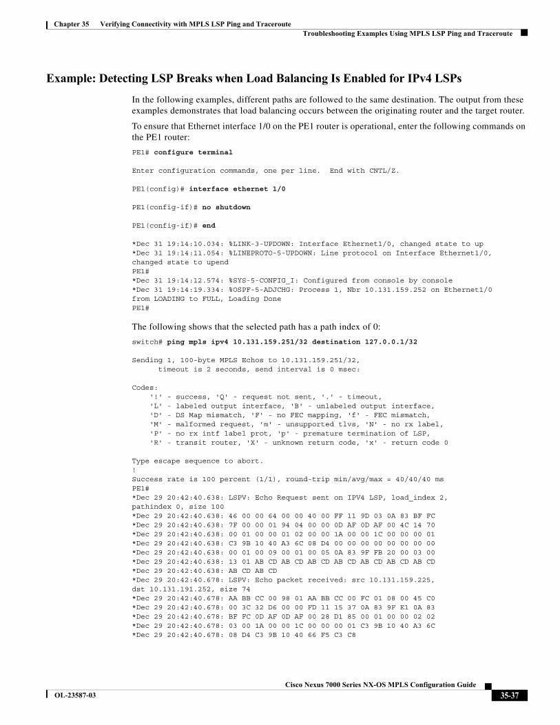
Chapter 35 Verifying Connectivity with MPLS LSP Ping and Traceroute Troubleshooting Examples Using MPLS LSP Ping and Traceroute
Example: Detecting LSP Breaks when Load Balancing Is Enabled for IPv4 LSPs
In the following examples, different paths are followed to the same destination. The output from these examples demonstrates that load balancing occurs between the originating router and the target router.
To ensure that Ethernet interface 1/0 on the PE1 router is operational, enter the following commands on the PE1 router:
PE1# configure terminal
Enter configuration commands, one per line. End with CNTL/Z.
PE1(config)# interface ethernet 1/0
PE1(config-if)# no shutdown
PE1(config-if)# end
*Dec 31 19:14:10.034: %LINK-3-UPDOWN: Interface Ethernet1/0, changed state to up*Dec 31 19:14:11.054: %LINEPROTO-5-UPDOWN: Line protocol on Interface Ethernet1/0,changed state to upendPE1# *Dec 31 19:14:12.574: %SYS-5-CONFIG_I: Configured from console by console*Dec 31 19:14:19.334: %OSPF-5-ADJCHG: Process 1, Nbr 10.131.159.252 on Ethernet1/0from LOADING to FULL, Loading DonePE1#
The following shows that the selected path has a path index of 0:
switch# ping mpls ipv4 10.131.159.251/32 destination 127.0.0.1/32
Sending 1, 100-byte MPLS Echos to 10.131.159.251/32,timeout is 2 seconds, send interval is 0 msec:
Codes:'!' - success, 'Q' - request not sent, '.' - timeout,'L' - labeled output interface, 'B' - unlabeled output interface,'D' - DS Map mismatch, 'F' - no FEC mapping, 'f' - FEC mismatch,'M' - malformed request, 'm' - unsupported tlvs, 'N' - no rx label,'P' - no rx intf label prot, 'p' - premature termination of LSP,'R' - transit router, 'X' - unknown return code, 'x' - return code 0
Type escape sequence to abort.!Success rate is 100 percent (1/1), round-trip min/avg/max = 40/40/40 msPE1#*Dec 29 20:42:40.638: LSPV: Echo Request sent on IPV4 LSP, load_index 2,pathindex 0, size 100*Dec 29 20:42:40.638: 46 00 00 64 00 00 40 00 FF 11 9D 03 0A 83 BF FC*Dec 29 20:42:40.638: 7F 00 00 01 94 04 00 00 0D AF 0D AF 00 4C 14 70*Dec 29 20:42:40.638: 00 01 00 00 01 02 00 00 1A 00 00 1C 00 00 00 01*Dec 29 20:42:40.638: C3 9B 10 40 A3 6C 08 D4 00 00 00 00 00 00 00 00*Dec 29 20:42:40.638: 00 01 00 09 00 01 00 05 0A 83 9F FB 20 00 03 00*Dec 29 20:42:40.638: 13 01 AB CD AB CD AB CD AB CD AB CD AB CD AB CD*Dec 29 20:42:40.638: AB CD AB CD*Dec 29 20:42:40.678: LSPV: Echo packet received: src 10.131.159.225, dst 10.131.191.252, size 74*Dec 29 20:42:40.678: AA BB CC 00 98 01 AA BB CC 00 FC 01 08 00 45 C0*Dec 29 20:42:40.678: 00 3C 32 D6 00 00 FD 11 15 37 0A 83 9F E1 0A 83*Dec 29 20:42:40.678: BF FC 0D AF 0D AF 00 28 D1 85 00 01 00 00 02 02*Dec 29 20:42:40.678: 03 00 1A 00 00 1C 00 00 00 01 C3 9B 10 40 A3 6C*Dec 29 20:42:40.678: 08 D4 C3 9B 10 40 66 F5 C3 C8
35-37Cisco Nexus 7000 Series NX-OS MPLS Configuration Guide
OL-23587-03
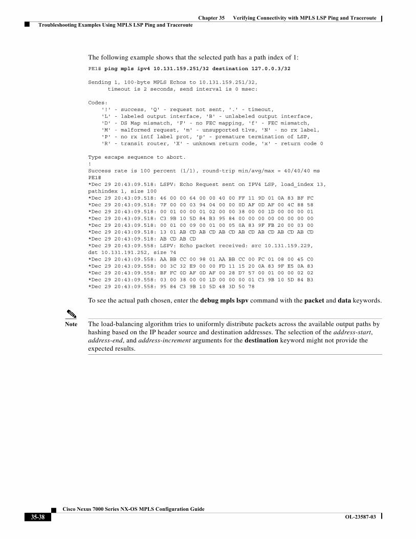
Chapter 35 Verifying Connectivity with MPLS LSP Ping and Traceroute Troubleshooting Examples Using MPLS LSP Ping and Traceroute
The following example shows that the selected path has a path index of 1:
PE1# ping mpls ipv4 10.131.159.251/32 destination 127.0.0.3/32
Sending 1, 100-byte MPLS Echos to 10.131.159.251/32,timeout is 2 seconds, send interval is 0 msec:
Codes:'!' - success, 'Q' - request not sent, '.' - timeout,'L' - labeled output interface, 'B' - unlabeled output interface,'D' - DS Map mismatch, 'F' - no FEC mapping, 'f' - FEC mismatch,'M' - malformed request, 'm' - unsupported tlvs, 'N' - no rx label,'P' - no rx intf label prot, 'p' - premature termination of LSP,'R' - transit router, 'X' - unknown return code, 'x' - return code 0
Type escape sequence to abort.!Success rate is 100 percent (1/1), round-trip min/avg/max = 40/40/40 msPE1#*Dec 29 20:43:09.518: LSPV: Echo Request sent on IPV4 LSP, load_index 13,pathindex 1, size 100*Dec 29 20:43:09.518: 46 00 00 64 00 00 40 00 FF 11 9D 01 0A 83 BF FC*Dec 29 20:43:09.518: 7F 00 00 03 94 04 00 00 0D AF 0D AF 00 4C 88 58*Dec 29 20:43:09.518: 00 01 00 00 01 02 00 00 38 00 00 1D 00 00 00 01*Dec 29 20:43:09.518: C3 9B 10 5D 84 B3 95 84 00 00 00 00 00 00 00 00*Dec 29 20:43:09.518: 00 01 00 09 00 01 00 05 0A 83 9F FB 20 00 03 00*Dec 29 20:43:09.518: 13 01 AB CD AB CD AB CD AB CD AB CD AB CD AB CD*Dec 29 20:43:09.518: AB CD AB CD*Dec 29 20:43:09.558: LSPV: Echo packet received: src 10.131.159.229,dst 10.131.191.252, size 74*Dec 29 20:43:09.558: AA BB CC 00 98 01 AA BB CC 00 FC 01 08 00 45 C0*Dec 29 20:43:09.558: 00 3C 32 E9 00 00 FD 11 15 20 0A 83 9F E5 0A 83*Dec 29 20:43:09.558: BF FC 0D AF 0D AF 00 28 D7 57 00 01 00 00 02 02*Dec 29 20:43:09.558: 03 00 38 00 00 1D 00 00 00 01 C3 9B 10 5D 84 B3*Dec 29 20:43:09.558: 95 84 C3 9B 10 5D 48 3D 50 78
To see the actual path chosen, enter the debug mpls lspv command with the packet and data keywords.
Note The load-balancing algorithm tries to uniformly distribute packets across the available output paths by hashing based on the IP header source and destination addresses. The selection of the address-start, address-end, and address-increment arguments for the destination keyword might not provide the expected results.
35-38Cisco Nexus 7000 Series NX-OS MPLS Configuration Guide
OL-23587-03
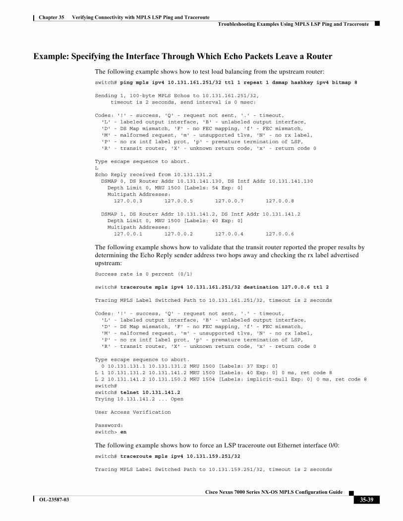
Chapter 35 Verifying Connectivity with MPLS LSP Ping and Traceroute Troubleshooting Examples Using MPLS LSP Ping and Traceroute
Example: Specifying the Interface Through Which Echo Packets Leave a Router
The following example shows how to test load balancing from the upstream router:
switch# ping mpls ipv4 10.131.161.251/32 ttl 1 repeat 1 dsmap hashkey ipv4 bitmap 8
Sending 1, 100-byte MPLS Echos to 10.131.161.251/32, timeout is 2 seconds, send interval is 0 msec:
Codes: '!' - success, 'Q' - request not sent, '.' - timeout,'L' - labeled output interface, 'B' - unlabeled output interface, 'D' - DS Map mismatch, 'F' - no FEC mapping, 'f' - FEC mismatch,'M' - malformed request, 'm' - unsupported tlvs, 'N' - no rx label, 'P' - no rx intf label prot, 'p' - premature termination of LSP, 'R' - transit router, 'X' - unknown return code, 'x' - return code 0
Type escape sequence to abort.LEcho Reply received from 10.131.131.2
DSMAP 0, DS Router Addr 10.131.141.130, DS Intf Addr 10.131.141.130Depth Limit 0, MRU 1500 [Labels: 54 Exp: 0]Multipath Addresses:
127.0.0.3 127.0.0.5 127.0.0.7 127.0.0.8
DSMAP 1, DS Router Addr 10.131.141.2, DS Intf Addr 10.131.141.2Depth Limit 0, MRU 1500 [Labels: 40 Exp: 0]Multipath Addresses:
127.0.0.1 127.0.0.2 127.0.0.4 127.0.0.6
The following example shows how to validate that the transit router reported the proper results by determining the Echo Reply sender address two hops away and checking the rx label advertised upstream:
Success rate is 0 percent (0/1)
switch# traceroute mpls ipv4 10.131.161.251/32 destination 127.0.0.6 ttl 2
Tracing MPLS Label Switched Path to 10.131.161.251/32, timeout is 2 seconds
Codes: '!' - success, 'Q' - request not sent, '.' - timeout,'L' - labeled output interface, 'B' - unlabeled output interface, 'D' - DS Map mismatch, 'F' - no FEC mapping, 'f' - FEC mismatch,'M' - malformed request, 'm' - unsupported tlvs, 'N' - no rx label, 'P' - no rx intf label prot, 'p' - premature termination of LSP, 'R' - transit router, 'X' - unknown return code, 'x' - return code 0
Type escape sequence to abort.0 10.131.131.1 10.131.131.2 MRU 1500 [Labels: 37 Exp: 0]
L 1 10.131.131.2 10.131.141.2 MRU 1500 [Labels: 40 Exp: 0] 0 ms, ret code 8L 2 10.131.141.2 10.131.150.2 MRU 1504 [Labels: implicit-null Exp: 0] 0 ms, ret code 8switch#switch# telnet 10.131.141.2Trying 10.131.141.2 ... Open
User Access Verification
Password: switch> en
The following example shows how to force an LSP traceroute out Ethernet interface 0/0:
switch# traceroute mpls ipv4 10.131.159.251/32
Tracing MPLS Label Switched Path to 10.131.159.251/32, timeout is 2 seconds
35-39Cisco Nexus 7000 Series NX-OS MPLS Configuration Guide
OL-23587-03
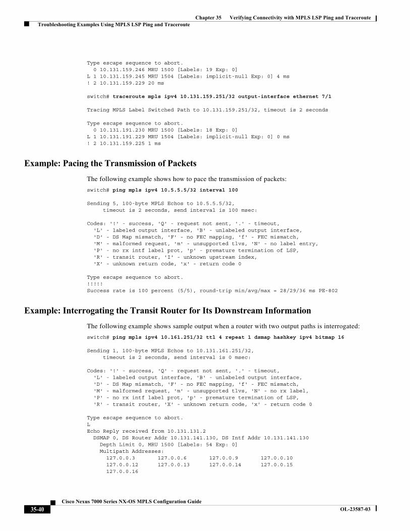
Chapter 35 Verifying Connectivity with MPLS LSP Ping and Traceroute Troubleshooting Examples Using MPLS LSP Ping and Traceroute
Type escape sequence to abort.0 10.131.159.246 MRU 1500 [Labels: 19 Exp: 0]
L 1 10.131.159.245 MRU 1504 [Labels: implicit-null Exp: 0] 4 ms! 2 10.131.159.229 20 ms
switch# traceroute mpls ipv4 10.131.159.251/32 output-interface ethernet 7/1
Tracing MPLS Label Switched Path to 10.131.159.251/32, timeout is 2 seconds
Type escape sequence to abort.0 10.131.191.230 MRU 1500 [Labels: 18 Exp: 0]
L 1 10.131.191.229 MRU 1504 [Labels: implicit-null Exp: 0] 0 ms! 2 10.131.159.225 1 ms
Example: Pacing the Transmission of Packets
The following example shows how to pace the transmission of packets:
switch# ping mpls ipv4 10.5.5.5/32 interval 100
Sending 5, 100-byte MPLS Echos to 10.5.5.5/32, timeout is 2 seconds, send interval is 100 msec:
Codes: '!' - success, 'Q' - request not sent, '.' - timeout,'L' - labeled output interface, 'B' - unlabeled output interface,'D' - DS Map mismatch, 'F' - no FEC mapping, 'f' - FEC mismatch,'M' - malformed request, 'm' - unsupported tlvs, 'N' - no label entry,'P' - no rx intf label prot, 'p' - premature termination of LSP,'R' - transit router, 'I' - unknown upstream index,'X' - unknown return code, 'x' - return code 0
Type escape sequence to abort.!!!!!Success rate is 100 percent (5/5), round-trip min/avg/max = 28/29/36 ms PE-802
Example: Interrogating the Transit Router for Its Downstream Information
The following example shows sample output when a router with two output paths is interrogated:
switch# ping mpls ipv4 10.161.251/32 ttl 4 repeat 1 dsmap hashkey ipv4 bitmap 16
Sending 1, 100-byte MPLS Echos to 10.131.161.251/32, timeout is 2 seconds, send interval is 0 msec:
Codes: '!' - success, 'Q' - request not sent, '.' - timeout,'L' - labeled output interface, 'B' - unlabeled output interface, 'D' - DS Map mismatch, 'F' - no FEC mapping, 'f' - FEC mismatch,'M' - malformed request, 'm' - unsupported tlvs, 'N' - no rx label, 'P' - no rx intf label prot, 'p' - premature termination of LSP, 'R' - transit router, 'X' - unknown return code, 'x' - return code 0
Type escape sequence to abort.LEcho Reply received from 10.131.131.2
DSMAP 0, DS Router Addr 10.131.141.130, DS Intf Addr 10.131.141.130Depth Limit 0, MRU 1500 [Labels: 54 Exp: 0]Multipath Addresses:
127.0.0.3 127.0.0.6 127.0.0.9 127.0.0.10127.0.0.12 127.0.0.13 127.0.0.14 127.0.0.15127.0.0.16
35-40Cisco Nexus 7000 Series NX-OS MPLS Configuration Guide
OL-23587-03
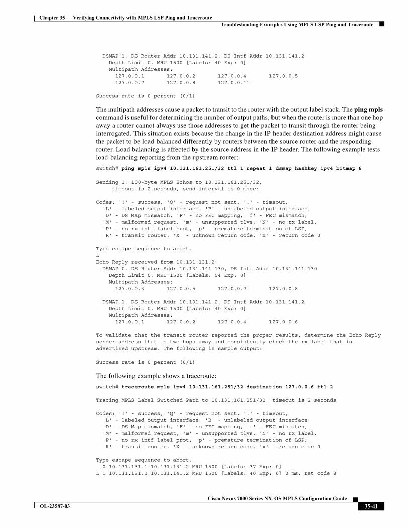
Chapter 35 Verifying Connectivity with MPLS LSP Ping and Traceroute Troubleshooting Examples Using MPLS LSP Ping and Traceroute
DSMAP 1, DS Router Addr 10.131.141.2, DS Intf Addr 10.131.141.2Depth Limit 0, MRU 1500 [Labels: 40 Exp: 0]Multipath Addresses:
127.0.0.1 127.0.0.2 127.0.0.4 127.0.0.5127.0.0.7 127.0.0.8 127.0.0.11
Success rate is 0 percent (0/1)
The multipath addresses cause a packet to transit to the router with the output label stack. The ping mpls command is useful for determining the number of output paths, but when the router is more than one hop away a router cannot always use those addresses to get the packet to transit through the router being interrogated. This situation exists because the change in the IP header destination address might cause the packet to be load-balanced differently by routers between the source router and the responding router. Load balancing is affected by the source address in the IP header. The following example tests load-balancing reporting from the upstream router:
switch# ping mpls ipv4 10.131.161.251/32 ttl 1 repeat 1 dsmap hashkey ipv4 bitmap 8
Sending 1, 100-byte MPLS Echos to 10.131.161.251/32, timeout is 2 seconds, send interval is 0 msec:
Codes: '!' - success, 'Q' - request not sent, '.' - timeout,'L' - labeled output interface, 'B' - unlabeled output interface, 'D' - DS Map mismatch, 'F' - no FEC mapping, 'f' - FEC mismatch,'M' - malformed request, 'm' - unsupported tlvs, 'N' - no rx label, 'P' - no rx intf label prot, 'p' - premature termination of LSP, 'R' - transit router, 'X' - unknown return code, 'x' - return code 0
Type escape sequence to abort.LEcho Reply received from 10.131.131.2
DSMAP 0, DS Router Addr 10.131.141.130, DS Intf Addr 10.131.141.130Depth Limit 0, MRU 1500 [Labels: 54 Exp: 0]Multipath Addresses:
127.0.0.3 127.0.0.5 127.0.0.7 127.0.0.8
DSMAP 1, DS Router Addr 10.131.141.2, DS Intf Addr 10.131.141.2Depth Limit 0, MRU 1500 [Labels: 40 Exp: 0]Multipath Addresses:
127.0.0.1 127.0.0.2 127.0.0.4 127.0.0.6
To validate that the transit router reported the proper results, determine the Echo Reply sender address that is two hops away and consistently check the rx label that is advertised upstream. The following is sample output:
Success rate is 0 percent (0/1)
The following example shows a traceroute:
switch# traceroute mpls ipv4 10.131.161.251/32 destination 127.0.0.6 ttl 2
Tracing MPLS Label Switched Path to 10.131.161.251/32, timeout is 2 seconds
Codes: '!' - success, 'Q' - request not sent, '.' - timeout,'L' - labeled output interface, 'B' - unlabeled output interface, 'D' - DS Map mismatch, 'F' - no FEC mapping, 'f' - FEC mismatch,'M' - malformed request, 'm' - unsupported tlvs, 'N' - no rx label, 'P' - no rx intf label prot, 'p' - premature termination of LSP, 'R' - transit router, 'X' - unknown return code, 'x' - return code 0
Type escape sequence to abort.0 10.131.131.1 10.131.131.2 MRU 1500 [Labels: 37 Exp: 0]
L 1 10.131.131.2 10.131.141.2 MRU 1500 [Labels: 40 Exp: 0] 0 ms, ret code 8
35-41Cisco Nexus 7000 Series NX-OS MPLS Configuration Guide
OL-23587-03
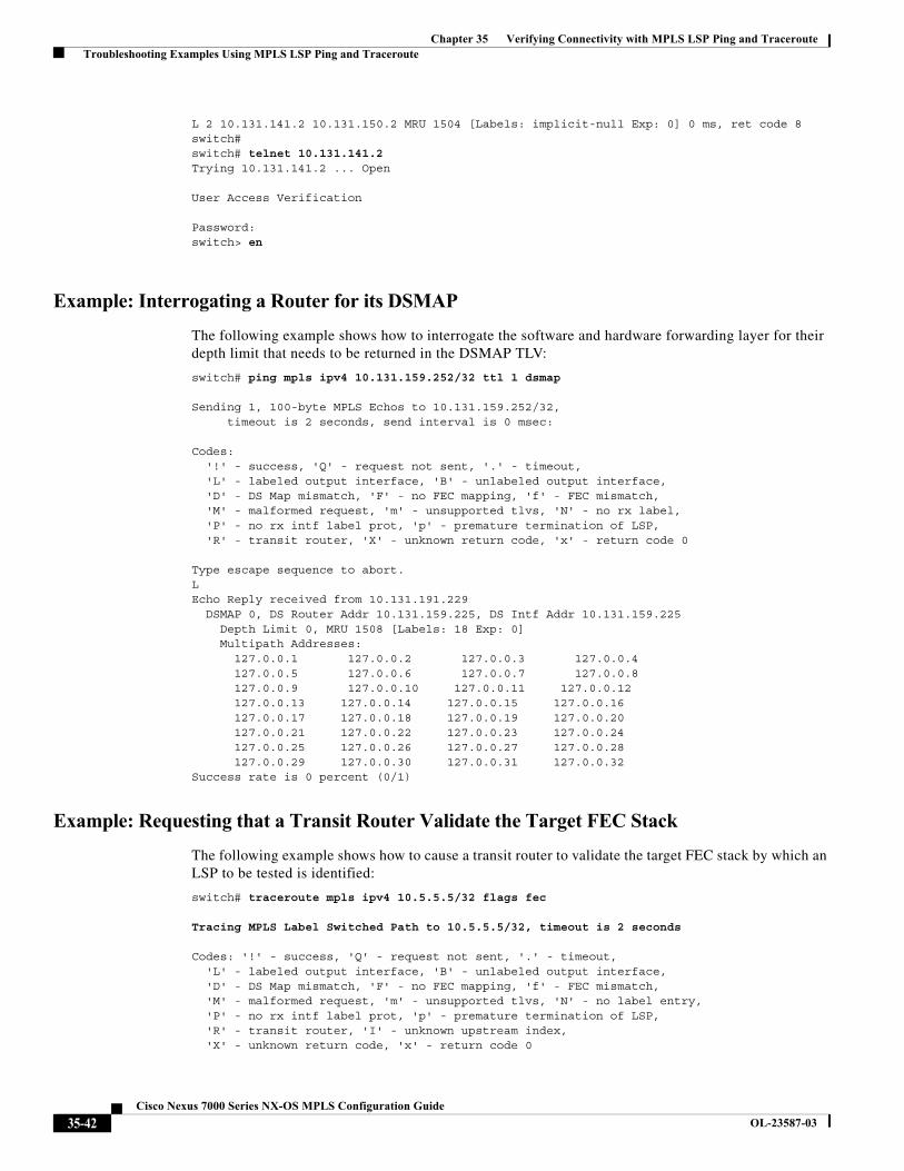
Chapter 35 Verifying Connectivity with MPLS LSP Ping and Traceroute Troubleshooting Examples Using MPLS LSP Ping and Traceroute
L 2 10.131.141.2 10.131.150.2 MRU 1504 [Labels: implicit-null Exp: 0] 0 ms, ret code 8switch#switch# telnet 10.131.141.2 Trying 10.131.141.2 ... Open
User Access Verification
Password: switch> en
Example: Interrogating a Router for its DSMAP
The following example shows how to interrogate the software and hardware forwarding layer for their depth limit that needs to be returned in the DSMAP TLV:
switch# ping mpls ipv4 10.131.159.252/32 ttl 1 dsmap
Sending 1, 100-byte MPLS Echos to 10.131.159.252/32, timeout is 2 seconds, send interval is 0 msec:
Codes: '!' - success, 'Q' - request not sent, '.' - timeout,'L' - labeled output interface, 'B' - unlabeled output interface,'D' - DS Map mismatch, 'F' - no FEC mapping, 'f' - FEC mismatch,'M' - malformed request, 'm' - unsupported tlvs, 'N' - no rx label,'P' - no rx intf label prot, 'p' - premature termination of LSP,'R' - transit router, 'X' - unknown return code, 'x' - return code 0
Type escape sequence to abort.LEcho Reply received from 10.131.191.229
DSMAP 0, DS Router Addr 10.131.159.225, DS Intf Addr 10.131.159.225Depth Limit 0, MRU 1508 [Labels: 18 Exp: 0]Multipath Addresses:
127.0.0.1 127.0.0.2 127.0.0.3 127.0.0.4127.0.0.5 127.0.0.6 127.0.0.7 127.0.0.8127.0.0.9 127.0.0.10 127.0.0.11 127.0.0.12127.0.0.13 127.0.0.14 127.0.0.15 127.0.0.16127.0.0.17 127.0.0.18 127.0.0.19 127.0.0.20127.0.0.21 127.0.0.22 127.0.0.23 127.0.0.24127.0.0.25 127.0.0.26 127.0.0.27 127.0.0.28127.0.0.29 127.0.0.30 127.0.0.31 127.0.0.32
Success rate is 0 percent (0/1)
Example: Requesting that a Transit Router Validate the Target FEC Stack
The following example shows how to cause a transit router to validate the target FEC stack by which an LSP to be tested is identified:
switch# traceroute mpls ipv4 10.5.5.5/32 flags fec
Tracing MPLS Label Switched Path to 10.5.5.5/32, timeout is 2 seconds
Codes: '!' - success, 'Q' - request not sent, '.' - timeout,'L' - labeled output interface, 'B' - unlabeled output interface,'D' - DS Map mismatch, 'F' - no FEC mapping, 'f' - FEC mismatch,'M' - malformed request, 'm' - unsupported tlvs, 'N' - no label entry,'P' - no rx intf label prot, 'p' - premature termination of LSP,'R' - transit router, 'I' - unknown upstream index,'X' - unknown return code, 'x' - return code 0
35-42Cisco Nexus 7000 Series NX-OS MPLS Configuration Guide
OL-23587-03
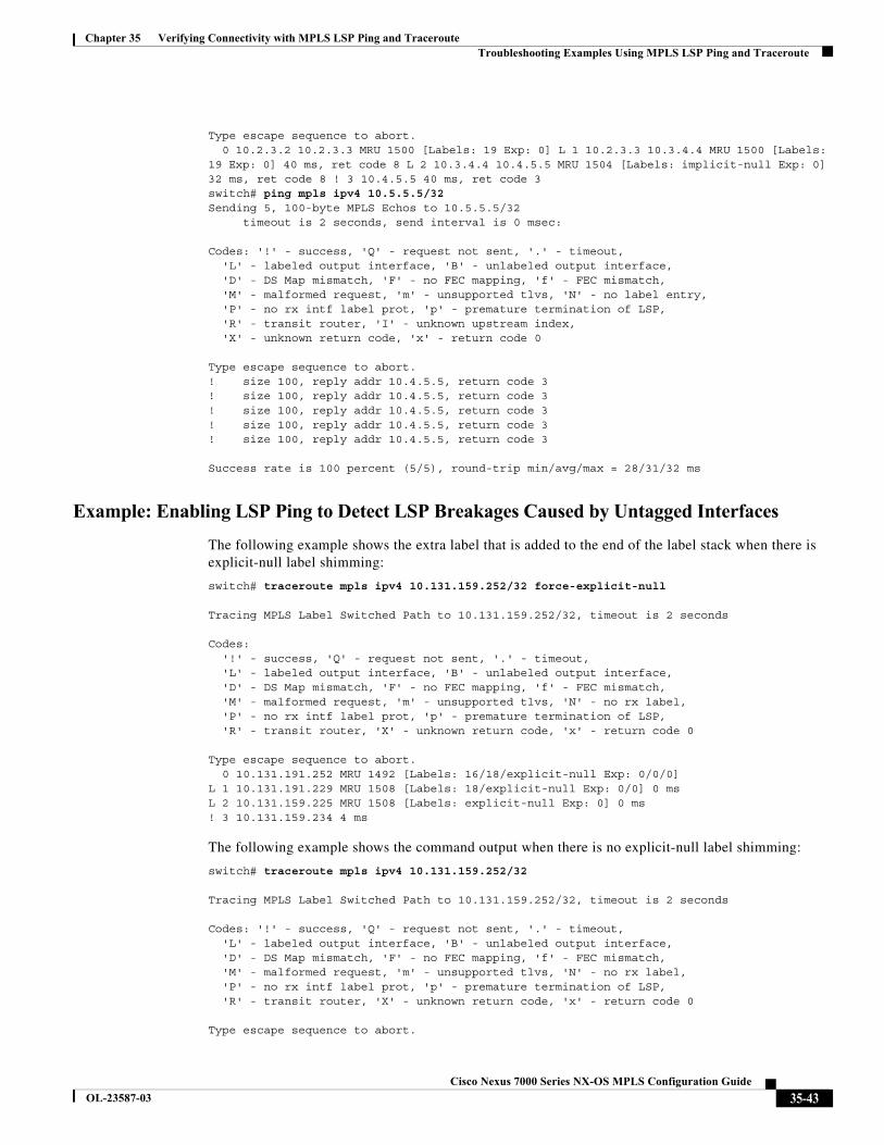
Chapter 35 Verifying Connectivity with MPLS LSP Ping and Traceroute Troubleshooting Examples Using MPLS LSP Ping and Traceroute
Type escape sequence to abort.0 10.2.3.2 10.2.3.3 MRU 1500 [Labels: 19 Exp: 0] L 1 10.2.3.3 10.3.4.4 MRU 1500 [Labels:
19 Exp: 0] 40 ms, ret code 8 L 2 10.3.4.4 10.4.5.5 MRU 1504 [Labels: implicit-null Exp: 0] 32 ms, ret code 8 ! 3 10.4.5.5 40 ms, ret code 3switch# ping mpls ipv4 10.5.5.5/32 Sending 5, 100-byte MPLS Echos to 10.5.5.5/32
timeout is 2 seconds, send interval is 0 msec:
Codes: '!' - success, 'Q' - request not sent, '.' - timeout,'L' - labeled output interface, 'B' - unlabeled output interface,'D' - DS Map mismatch, 'F' - no FEC mapping, 'f' - FEC mismatch,'M' - malformed request, 'm' - unsupported tlvs, 'N' - no label entry,'P' - no rx intf label prot, 'p' - premature termination of LSP,'R' - transit router, 'I' - unknown upstream index,'X' - unknown return code, 'x' - return code 0
Type escape sequence to abort.! size 100, reply addr 10.4.5.5, return code 3! size 100, reply addr 10.4.5.5, return code 3! size 100, reply addr 10.4.5.5, return code 3! size 100, reply addr 10.4.5.5, return code 3! size 100, reply addr 10.4.5.5, return code 3
Success rate is 100 percent (5/5), round-trip min/avg/max = 28/31/32 ms
Example: Enabling LSP Ping to Detect LSP Breakages Caused by Untagged Interfaces
The following example shows the extra label that is added to the end of the label stack when there is explicit-null label shimming:
switch# traceroute mpls ipv4 10.131.159.252/32 force-explicit-null
Tracing MPLS Label Switched Path to 10.131.159.252/32, timeout is 2 seconds
Codes: '!' - success, 'Q' - request not sent, '.' - timeout,'L' - labeled output interface, 'B' - unlabeled output interface,'D' - DS Map mismatch, 'F' - no FEC mapping, 'f' - FEC mismatch,'M' - malformed request, 'm' - unsupported tlvs, 'N' - no rx label,'P' - no rx intf label prot, 'p' - premature termination of LSP,'R' - transit router, 'X' - unknown return code, 'x' - return code 0
Type escape sequence to abort.0 10.131.191.252 MRU 1492 [Labels: 16/18/explicit-null Exp: 0/0/0]
L 1 10.131.191.229 MRU 1508 [Labels: 18/explicit-null Exp: 0/0] 0 ms L 2 10.131.159.225 MRU 1508 [Labels: explicit-null Exp: 0] 0 ms ! 3 10.131.159.234 4 ms
The following example shows the command output when there is no explicit-null label shimming:
switch# traceroute mpls ipv4 10.131.159.252/32
Tracing MPLS Label Switched Path to 10.131.159.252/32, timeout is 2 seconds
Codes: '!' - success, 'Q' - request not sent, '.' - timeout,'L' - labeled output interface, 'B' - unlabeled output interface,'D' - DS Map mismatch, 'F' - no FEC mapping, 'f' - FEC mismatch,'M' - malformed request, 'm' - unsupported tlvs, 'N' - no rx label,'P' - no rx intf label prot, 'p' - premature termination of LSP,'R' - transit router, 'X' - unknown return code, 'x' - return code 0
Type escape sequence to abort.
35-43Cisco Nexus 7000 Series NX-OS MPLS Configuration Guide
OL-23587-03
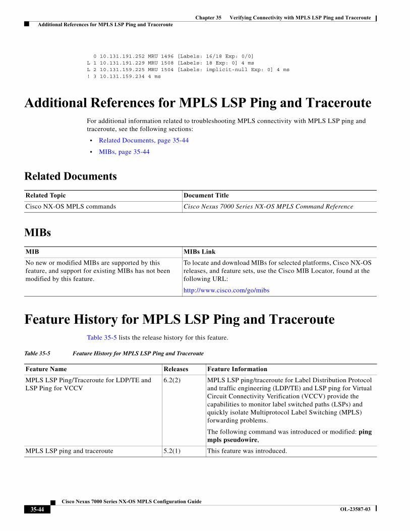
Chapter 35 Verifying Connectivity with MPLS LSP Ping and Traceroute Additional References for MPLS LSP Ping and Traceroute
0 10.131.191.252 MRU 1496 [Labels: 16/18 Exp: 0/0] L 1 10.131.191.229 MRU 1508 [Labels: 18 Exp: 0] 4 ms L 2 10.131.159.225 MRU 1504 [Labels: implicit-null Exp: 0] 4 ms ! 3 10.131.159.234 4 ms
Additional References for MPLS LSP Ping and TracerouteFor additional information related to troubleshooting MPLS connectivity with MPLS LSP ping and traceroute, see the following sections:
• Related Documents, page 35-44
• MIBs, page 35-44
Related Documents
MIBs
Feature History for MPLS LSP Ping and TracerouteTable 35-5 lists the release history for this feature.
Related Topic Document Title
Cisco NX-OS MPLS commands Cisco Nexus 7000 Series NX-OS MPLS Command Reference
MIB MIBs Link
No new or modified MIBs are supported by this feature, and support for existing MIBs has not been modified by this feature.
To locate and download MIBs for selected platforms, Cisco NX-OS releases, and feature sets, use the Cisco MIB Locator, found at the following URL:
http://www.cisco.com/go/mibs
Table 35-5 Feature History for MPLS LSP Ping and Traceroute
Feature Name Releases Feature Information
MPLS LSP Ping/Traceroute for LDP/TE and LSP Ping for VCCV
6.2(2) MPLS LSP ping/traceroute for Label Distribution Protocol and traffic engineering (LDP/TE) and LSP ping for Virtual Circuit Connectivity Verification (VCCV) provide the capabilities to monitor label switched paths (LSPs) and quickly isolate Multiprotocol Label Switching (MPLS) forwarding problems.
The following command was introduced or modified: ping mpls pseudowire,
MPLS LSP ping and traceroute 5.2(1) This feature was introduced.
35-44Cisco Nexus 7000 Series NX-OS MPLS Configuration Guide
OL-23587-03