vectorworks sdk manual - nemetschek groupdownload2cf.nemetschek.net/ sdk manual 6 section i: the...
TRANSCRIPT
Vectorworks SDK Manual
For Vectorworks 2018
7150 Riverwood Drive Columbia, MD 21046 Telephone: 410-290-5114 Fax: 410-290-8050 www.vectorworks.net

COPYRIGHT 2016 Vectorworks Inc. All Rights Reserved.
QuickTime and the QuickTime logo are trademarks used under license.
Documentation by: Andrew Campbell, Mark Farnan, Lyndsey Ferguson, Sean Flaherty, Jeff Geraci, Steve
Johnson, Jeffrey Koppi, Chris Nebel, and Paul Pharr. Layout by Sean Flaherty, John Ferdock, Jeffrey
Koppi and Don Webster.
This document was illustrated using Vectorworks.
Contents
INTRODUCTION ........................................................................................................................................ 5
Document Layout.................................................................................................................................... 5 Included Files ......................................................................................................................................... 5
SECTION I: THE PLUG-IN ENVIRONMENT ....................................................................................... 6
The Plug-in and the User........................................................................................................................ 6 The Definition of a Plug-in ..................................................................................................................... 7 Tool or Menu Command? ....................................................................................................................... 8 Communication Between Vectorworks and Plug-ins .............................................................................. 8 Global Data ............................................................................................................................................ 8
MENU COMMANDS .....................................................................................................................................10 Menu Command Main Function ............................................................................................................10 Menu Command Actions ........................................................................................................................11 Menu Command Definition Resource: MITM .......................................................................................13
TOOLS ........................................................................................................................................................16 Tool Main Function ...............................................................................................................................16 Tool Actions ...........................................................................................................................................16 Tool Definition Resource: TDef ............................................................................................................19 Tool Icon................................................................................................................................................20 Tool Related Callbacks ..........................................................................................................................21
PLUG-IN OBJECTS .......................................................................................................................................22 Plug-in Object Types .............................................................................................................................22 Tool for Plug-in Object .........................................................................................................................23 Plug-in Object Main Function ...............................................................................................................23 Plug-in Object Actions ..........................................................................................................................24 Plug-in Object Resources ......................................................................................................................25 Custom User Interface ...........................................................................................................................27
PLUG-IN LIBRARY ROUTINES .....................................................................................................................30 Plug-in Library Routines Main Function ..............................................................................................30 Plug-in Library Routine Resources .......................................................................................................31 Calling a Library Routine......................................................................................................................31 Memory Management and Other Options .............................................................................................32
SECTION II: THE VECTORWORKS ENVIRONMENT .....................................................................34
Entities ...................................................................................................................................................34 Lists .......................................................................................................................................................34 Drawings ...............................................................................................................................................34 List Traversal ........................................................................................................................................35
UNITS .........................................................................................................................................................36 PROPERTIES OF DRAWING ENTITIES ...........................................................................................................37 SPECIAL OBJECTS .......................................................................................................................................38
Symbols ..................................................................................................................................................38 Walls ......................................................................................................................................................39 Extrudes .................................................................................................................................................40 Sweeps ...................................................................................................................................................40 Meshes ...................................................................................................................................................40
3D VIEWS ...................................................................................................................................................41 UNDO .........................................................................................................................................................42 USER INTERFACE ........................................................................................................................................46
Display of Numeric Values ....................................................................................................................51
SECTION III: THE DEVELOPMENT ENVIRONMENT .....................................................................53
CROSS-PLATFORM DEVELOPMENT .............................................................................................................53
Macintosh Project and Compiler Settings .............................................................................................53 Windows Project and Compiler Settings ...............................................................................................53
RESOURCES ................................................................................................................................................54 DEBUGGING ...............................................................................................................................................55 APPLICATION FRAMEWORKS ......................................................................................................................56
SECTION IV: VCOM – VECTORWORKS COMPONENT OBJECT MODEL ................................57
WHAT IS VCOM ........................................................................................................................................57 CLIENT: USING VCOM ...............................................................................................................................57 PROVIDER: MAKING INTERFACE PROVIDER ................................................................................................59 LOCATING THE INTERFACES VECTORWORKS PROVIDES .............................................................................61 IMPORTANT THINGS FOR VCOM ................................................................................................................62
What is ‘IVWUnknown’? .......................................................................................................................62 Never forget to ‘Release’ queried interfaces. ........................................................................................63 Use reference counting. .........................................................................................................................63
INDEX ..........................................................................................................................................................64

Vectorworks SDK Manual 5
Introduction Vectorworks provides an open architecture that allows developers to supplement or replace existing
Vectorworks functionality. From the user’s perspective, these new plug-in tools, menu commands, and
objects are indistinguishable from those built into Vectorworks. As such, they are first class solutions for
the user. The purpose of this document is to define the relationship between the user, the plug-in, and the
Vectorworks application. It also describes how to implement a new plug-in from these specifications.
Document Layout
This document is divided into three sections. The first section describes plug-ins and the plug-in
environment. The second section describes how Vectorworks documents are organized, and describes
some of the services that the application provides to plug-ins. The final section discusses the development
environment.
Included Files
In addition to this document, the SDK includes release notes, a function reference, and other documents. It
also includes the source code and libraries necessary to build plug-ins. Full source code for several sample
plug-ins is also provided.
Vectorworks SDK Manual 6
Section I: The Plug-in Environment The Vectorworks open environment is composed of 4 pieces: the user, the plug-in, the drawing, and the
Vectorworks application. The user works with the plug-in to manipulate the drawing. Vectorworks
provides the means of communication between the other parts as well as the essential functionality of a
CAD system (coordinate systems, objects, math routines, etc.).
The system works because each part has a well-defined role and each part, except one, has a well-defined
protocol to carry out its role. The one exception is, of course, the user, who will not submit to any protocol.
The other parts must be tolerant of unexpected user input, and provide information to the user so that he or
she will naturally make the right choices.
The user’s role is to generate events, from mouse movement and button clicks to requests for a
wall or to rotate the world. The user is the action to which everything else reacts.
The drawing is the data that the user creates. Its job is to exist.
Vectorworks’ role is the enabler. It provides the framework in which the other parts meet.
The role of the plug-in is to respond to the user, servicing his or her requests to create and
manipulate the drawing, thereby building on the Vectorworks framework useful software. In less
grand terms, a tool or menu command solves a user problem with the help of Vectorworks.
The Plug-in and the User
As stated above, the user will relate to the plug-in in any way he or she pleases. A plug-in, however, in
dealing with the user, must provide the following:
Functionality - This is not that difficult to do. If you are reading this document then you probably
have some ideas, ranging from the just plain silly to the revolutionary. The difficult thing about
functionality is making it useful. The rest of the requirements exist to help do this (though they
are by no means sufficient).
Undo - Documentation may guide the user to your plug-in. Help messages may reassure them.
But only experience teaches them. If your plug-in permanently modifies the drawing in any way,
you must preserve the user’s guarantee to experiment freely by providing undo. Vectorworks
offers a simple, powerful and generic undo facility for use in a plug-in. For information on how to
implement undo, see the subsection on undo in the services section.
Help - All plug-ins have help tags (tool tips) that concisely state the purpose of the plug-in. It
appears when the user positions the cursor over the tool or menu command. In addition, plug-in
developers can provide context sensitive help. This help is contained in html files on the user’s
hard drive or on the internet. For information on how to provide context sensitive help, see the
subsection on context sensitive help in the services section.
Message bar help - When a tool is selected text can be displayed in the message bar. A plug-in
should display the name of the current tool mode, and prompt the user towards the next expected
action
Smart Cursor - Vectorworks uses the cursor to provide information to the user about a tool.
Which cursor a tool uses should indicate to the user what task the tool will perform next. An
example is how the selection tool changes from a hollow arrow when the cursor is over an object
to the standard arrow cursor when the next click will allow specification of a selection marquee.
Make use of existing Vectorworks cursors and conventions where possible and make logical
extensions otherwise. Some tools may need a completely new cursor. If a tool’s behavior
depends on the object it is being used with or on some state internal to the tool, then the
appearance of the cursor should convey this.
Alerts - If the user attempts to use the plug-in in a way that is inappropriate or impossible, the
plug-in should provide information about what is wrong and how to correct the situation. A plug-
in should never fail without an explanation or with only a beep.
Vectorworks SDK Manual 7
Constraints - Constraints allow the user to control a plug-in’s behavior and enhance its usefulness.
See the constraints subsection in the services section for a discussion of how to make a tool work
with the constraint palette.
Menu Highlighting - Menu commands have the option to make themselves unavailable when the
conditions for their use are not met. Disabling a menu does not provide information. It only
limits choices. A menu should not disable itself unless it is clear to the user why the functionality
is inappropriate at that time. If it is unclear then the menu command should remain enabled. If
the user selects it, it can provide an alert telling the user it is unavailable. The alert explains what
conditions need to change for the menu command to be activated.
The Definition of a Plug-in
Implementation of a plug-in can be broken into two parts: writing the program source code that defines the
plug-in and creating the proper resources. On the Macintosh platform, these components are combined into
a single package that the user places into their “Plug-ins” folder. On Windows, the code and resources
exist in separate files, both of which are placed into the “Plug-ins” folder.
Some of the Macintosh resources described below are custom resources defined by Vectorworks
specifically for the Vectorworks SDK. Refer to Section III: The Development Environment for more
information on editing these custom resource types. A Windows Plug-in may also contain Windows
Resources.
The following resources will be found in a completed plug-in:
Definition Resource. Each type of plug-in has a resource type that defines certain standard
behavior for the plug-in. For a menu command the resource type is MITM, for a tool the type is
TDef, for an object it is ‘PDEf’, and for a library routine it is ‘VLIB’. Every plug-in must have a
valid definition resource with an ID of 128. These are custom resources defined by Vectorworks,
and are described in more detail later in this section.
Auxiliary Resources. Recommended resources for most plug-ins.
‘TEXT’
This resource holds the text for the help tag (tool tip) and must have a resource ID of 128. The length
of this resource must be less than 239 characters. Help tags are managed by Vectorworks
automatically when you provide this resource. If you add or edit this resource in the plug-in you will
need to edit all Workspaces containing that plug-in to force the new help to appear.
‘vers’
All plug-ins must have vers resources of ID 1 and optionally of ID 2. ‘vers’ 1 is the plug-in’s version.
‘vers’ 2 is the version of the package that the plug-in was shipped with. Vectorworks plug-ins use
‘vers’ 2 to specify which version of Vectorworks the plug-in shipped with. If your plug-in exists
independently then it does not need a ‘vers’ 2 resource.
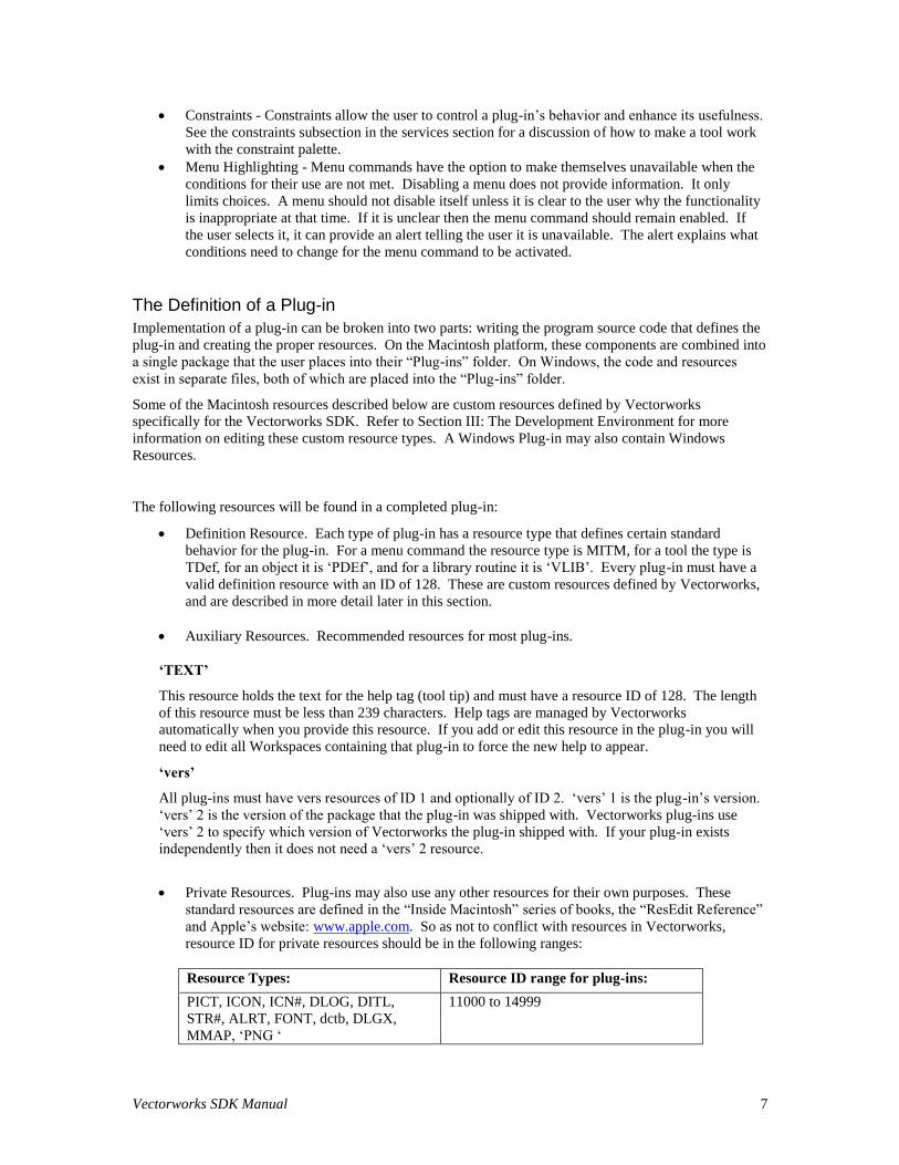
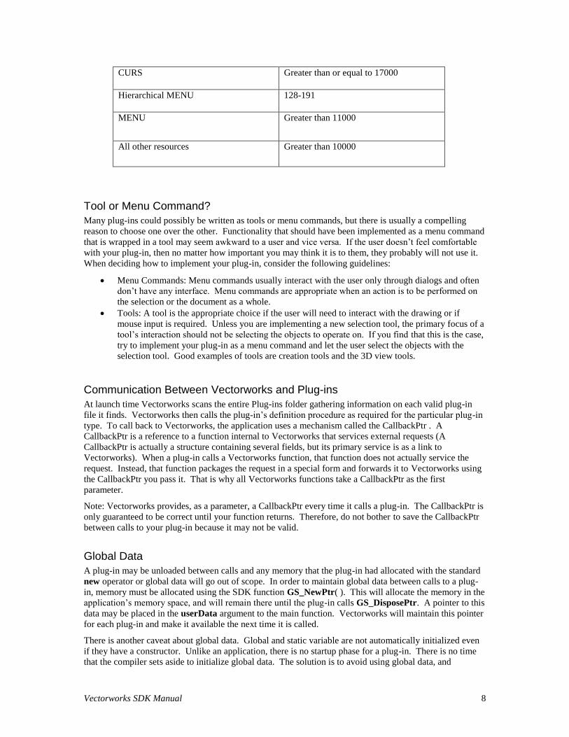
Private Resources. Plug-ins may also use any other resources for their own purposes. These
standard resources are defined in the “Inside Macintosh” series of books, the “ResEdit Reference”
and Apple’s website: www.apple.com. So as not to conflict with resources in Vectorworks,
resource ID for private resources should be in the following ranges:
Resource Types: Resource ID range for plug-ins:
PICT, ICON, ICN#, DLOG, DITL,
STR#, ALRT, FONT, dctb, DLGX,
MMAP, ‘PNG ‘
11000 to 14999
Vectorworks SDK Manual 8
CURS Greater than or equal to 17000
Hierarchical MENU 128-191
MENU Greater than 11000
All other resources Greater than 10000
Tool or Menu Command?
Many plug-ins could possibly be written as tools or menu commands, but there is usually a compelling
reason to choose one over the other. Functionality that should have been implemented as a menu command
that is wrapped in a tool may seem awkward to a user and vice versa. If the user doesn’t feel comfortable
with your plug-in, then no matter how important you may think it is to them, they probably will not use it.
When deciding how to implement your plug-in, consider the following guidelines:
Menu Commands: Menu commands usually interact with the user only through dialogs and often
don’t have any interface. Menu commands are appropriate when an action is to be performed on
the selection or the document as a whole.
Tools: A tool is the appropriate choice if the user will need to interact with the drawing or if
mouse input is required. Unless you are implementing a new selection tool, the primary focus of a
tool’s interaction should not be selecting the objects to operate on. If you find that this is the case,
try to implement your plug-in as a menu command and let the user select the objects with the
selection tool. Good examples of tools are creation tools and the 3D view tools.
Communication Between Vectorworks and Plug-ins
At launch time Vectorworks scans the entire Plug-ins folder gathering information on each valid plug-in
file it finds. Vectorworks then calls the plug-in’s definition procedure as required for the particular plug-in
type. To call back to Vectorworks, the application uses a mechanism called the CallbackPtr . A
CallbackPtr is a reference to a function internal to Vectorworks that services external requests (A
CallbackPtr is actually a structure containing several fields, but its primary service is as a link to
Vectorworks). When a plug-in calls a Vectorworks function, that function does not actually service the
request. Instead, that function packages the request in a special form and forwards it to Vectorworks using
the CallbackPtr you pass it. That is why all Vectorworks functions take a CallbackPtr as the first
parameter.
Note: Vectorworks provides, as a parameter, a CallbackPtr every time it calls a plug-in. The CallbackPtr is
only guaranteed to be correct until your function returns. Therefore, do not bother to save the CallbackPtr
between calls to your plug-in because it may not be valid.
Global Data
A plug-in may be unloaded between calls and any memory that the plug-in had allocated with the standard
new operator or global data will go out of scope. In order to maintain global data between calls to a plug-
in, memory must be allocated using the SDK function GS_NewPtr( ). This will allocate the memory in the
application’s memory space, and will remain there until the plug-in calls GS_DisposePtr. A pointer to this
data may be placed in the userData argument to the main function. Vectorworks will maintain this pointer
for each plug-in and make it available the next time it is called.
There is another caveat about global data. Global and static variable are not automatically initialized even
if they have a constructor. Unlike an application, there is no startup phase for a plug-in. There is no time
that the compiler sets aside to initialize global data. The solution is to avoid using global data, and

Vectorworks SDK Manual 9
especially data of non-primitive types. If you must use a custom type for global data (which is not
unlikely), then make the global data a pointer or handle, and allocate the object during each call of your
plug-in that needs it. Constructors are always called when an object is allocated with new.
Vectorworks SDK Manual 10
Menu Commands
The SDK supports several types of Menu Commands. A plug-in Menu Command can be either a single
basic menu command or a block of several related menu commands, which is referred to as a menu chunk.
A Basic menu command implements a single menu item in a menu. Basic menu commands have no
support for item checking, run-time item disabling, or multiple commands in a single plug-in. If you need
any of these behaviors you can create a menu chunk.
A menu chunk displays several menu commands together in a menu, and shares the same source code.
This is often desirable when the user needs to select between a group of related options that perform a very
similar function.
All menus in Vectorworks, both internal and external, use the same framework of MITM resources,
MMNU resources, and menu definition functions. Chunks, being the most general type of menu items,
must support the widest array of options. Because of their generality, chunks require more setup and have
more associated complications than single menu items.
There are three types of chunks:
Plain chunks contain a fixed number of items that are defined in the resource file in an MMNU
resource. The size of these is fixed when they are implemented.
Dynamic chunks are constructed at runtime by the menu definition function. They can be any size,
but the size cannot be changed after initialization. The Workspaces menu is an example of a dynamic
chunk.
Variable-dynamic chunks are similar to dynamic chunks in that they are constructed at runtime. They
are more flexible, however, because they can change their size at any time. The Layers menu, and
Windows menu are examples of variable-dynamic chunks.
Because dynamic and variable-dynamic chunks have an unknown size when the menus are being built, the
Workspace Editor only allows them to be placed at the end of a menu. Typically, they are placed in a
hierarchical menu.
Menu Command Main Function
The prototype for a Menu Command’s main function is:
extern “C” long plugin_main(long action, long message, long& userData,
CallBackPtr cbp)
The parameters to the main function are:
action Identifies the task the menu command needs to perform, and determines the significance
of the message parameter. The actions are described in detail below.
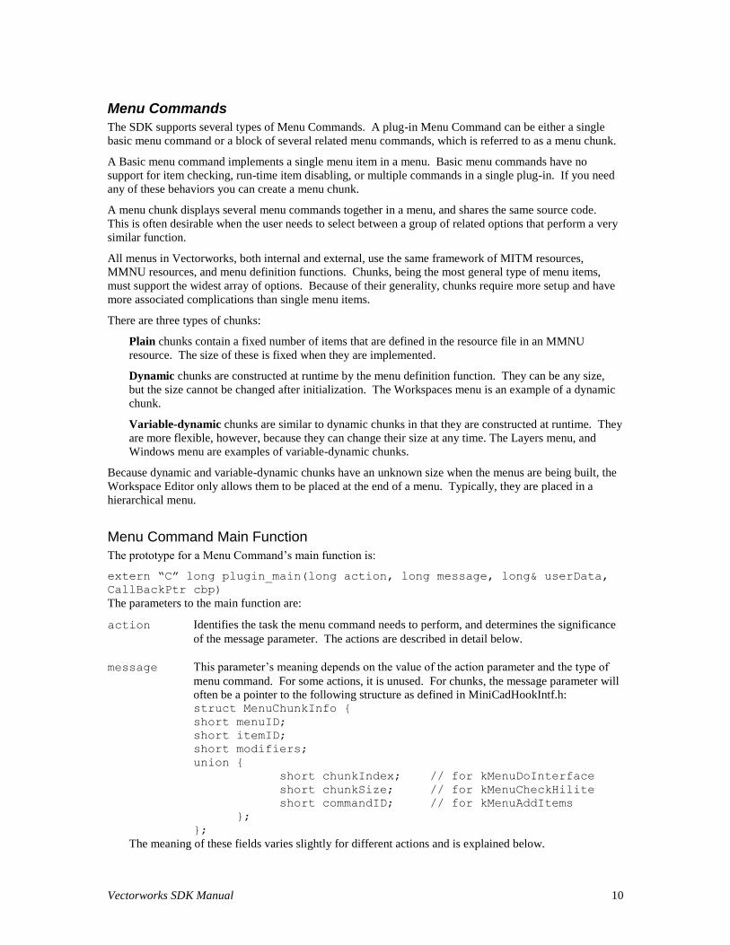
message This parameter’s meaning depends on the value of the action parameter and the type of
menu command. For some actions, it is unused. For chunks, the message parameter will
often be a pointer to the following structure as defined in MiniCadHookIntf.h: struct MenuChunkInfo {
short menuID;
short itemID;
short modifiers;
union {
short chunkIndex; // for kMenuDoInterface
short chunkSize; // for kMenuCheckHilite
short commandID; // for kMenuAddItems
};
};
The meaning of these fields varies slightly for different actions and is explained below.
Vectorworks SDK Manual 11
userData Four bytes of data that Vectorworks maintains for the plug-in between calls. This is
necessary because a plug-in cannot directly maintain its state between calls. The section
on the Development Environment explains in great detail the peculiarities of plug-ins and
global variables.
cbp An implementation detail. See the documentation in Section III for more information.
Menu Command Actions
The menu command main function will be called by Vectorworks, and will be passed one of several values
for the action parameter indicating the task to be performed. Basic and Chunk menu commands must
respond to the following values for the action parameter:
kMenuInitGlobals
A workspace containing the plug-in has been loaded. This is the plug-in’s opportunity to allocate and
initialize all persistent data. A Macintosh handle to the data should be assigned to the userData
parameter so that it can be used later for other actions. The message parameter is unused. This action
should always return 0. This action will not be called again until a kMenuDisposeGlobals is passed.
kMenuDisposeGlobals
A workspace containing the plug-in has been deselected. The menu command should finalize all
outstanding actions and free any allocated data and resources. The message parameter is unused. This
action should always return 0.
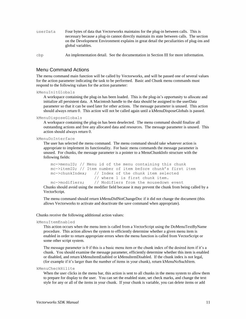
kMenuDoInterface
The user has selected the menu command. The menu command should take whatever action is
appropriate to implement its functionality. For basic menu commands the message parameter is
unused. For chunks, the message parameter is a pointer to a MenuChunkInfo structure with the
following fields:
mc->menuID; // Menu id of the menu containing this chunk
mc->itemID; // Item number of item before chunk’s first item
mc->chunkIndex; // Index of the chunk item selected
// where 1 is first chunk item.
mc->modifiers; // Modifiers from the mousedown event
Chunks should avoid using the modifier field because it may prevent the chunk from being called by a
VectorScript.
The menu command should return kMenuDidNotChangeDoc if it did not change the document (this
allows Vectorworks to activate and deactivate the save command when appropriate).
Chunks receive the following additional action values:
kMenuItemEnabled
This action occurs when the menu item is called from a VectorScript using the DoMenuTextByName
procedure. This action allows the system to efficiently determine whether a given menu item is
enabled in order to return appropriate errors when the menu function is called from VectorScript or
some other script system.
The message parameter is 0 if this is a basic menu item or the chunk index of the desired item if it’s a
chunk. You should examine the message parameter, efficiently determine whether this item is enabled
or disabled, and return kMenuItemEnabled or kMenuItemDisabled. If the chunk index is not legal,
(for example if it’s larger than the number of items in your chunk), return kMenuNoSuchItem.
kMenuCheckHilite
When the user clicks in the menu bar, this action is sent to all chunks in the menu system to allow them
to prepare for display to the user. You can set the enabled state, set check marks, and change the text
style for any or all of the items in your chunk. If your chunk is variable, you can delete items or add
Vectorworks SDK Manual 12
new items in response to the current state of the drawing. You can use any standard menu manager
routines to set up your chunk for display to the user.
Since all this must happen after the user clicks the mouse but before the menu is displayed, this is a
time critical section of code. You should make every effort to avoid doing unnecessary work when
you get this action.
The message parameter is a pointer to a MenuChunkInfo structure with the following fields:
mc->menuID; // The menu id of the menu containing this chunk
mc->itemID; // The itemID of the first item in the chunk
mc->chunkSize; // The number of items in this chunk
mc->modifiers; // The modifiers from the mousedown event
Return true if this call is necessary, false otherwise. (Return true if any items were disabled.)
Note: Avoid using the modifiers field of the MenuChunkInfo. Your menu item cannot be called
correctly from VectorScript or other script systems if it depends on this information.
Warning: The resource fork of your plug-in file is not open when your code gets this message (for
speed reasons). Your code cannot load resources from its file or make calls to code outside the main
segment. This is a severe restriction, so be very careful when implementing the code for this action.
kMenuNotify
This action notifies the menu chunk that a particular Vectorworks internal event has occurred. The
menu must have previously registered for the notification. This is typically done in the
kMenuInitGlobals action. For example, to register for the “Document Changed” notification you
would call:
RegisterMenuForCallback(cbp,GetMyMenuCommandIndex(cbp),’DOCC’);
The menu will continue to receive a kMenuNotify action every time the active document changes until
it unregisters by calling the function:
UnregisterMenuForCallback(cbp,GetMyMenuCommandIndex(cbp),’DOCC’);
The message parameter for this action indicates which event has occurred. The message is a 32-bit
value of type OSType that can be represented as a four-character code. For example, the menu can test
the message value as follows:
If (message == ‘DOCC’) {
(*(MyInfoHandle)userData)->needsDocRebuild = true;
}
The menu can respond to the notification immediately or it can set a global flag for use later (as shown
in the example above). Often it is best to postpone any significant work until it is required.
This action should always return 0.
Warning: The resource fork of your plug-in file is not open when your code gets this message (for
speed reasons). Your code cannot load resources from its file or make calls to code outside the main
segment. This is a severe restriction, so be very careful when implementing the code for this action.
kMenuAddItems
The menu that contains this chunk has been constructed up to the item before your chunk. Add any
items you want in your chunk to the end of this menu.
This action is only passed to dynamic and variable-dynamic chunks. Basic menu commands and plain
chunks do not receive this action. It occurs once, immediately after kMenuInitGlobals and before any
other action. If a variable-dynamic chunk can determine all of its items at this point it should do so.
The message parameter is a pointer to a MenuChunkInfo structure with the fields:
mc->menuID; // Menu id of the menu containing this chunk
Vectorworks SDK Manual 13
mc->itemID; // Item number of item before the chunk’s first item
mc->chunkIndex; // unused
mc->modifiers; // unused
Typecast the message parameter and then use it to retrieve the MenuHandle to your menu. Using this
handle, you can add your chunk’s items to the end of the menu with AppendMenu as follows:
MenuChunkInfoPtr mc = (MenuChunkInfoPtr) message;
MenuHandle myMenu = GetMenuHandle(mc->menuID);
AppendMenu(myMenu, “\pItem One”);
AppendMenu(myMenu, “\pItem Two”);
AppendMenu(myMenu, “\pItem Three”);
If you would like to display the special characters ; ! > / ( in your menu item, you must use the
following technique:
AppendMenu(myMenu, “\pdummy”);
SetItem(myMenu, mc->itemID+1, “\pCalculate miles / gallon”);
This action should always return 0.
If the items in your variable-dynamic chunk can change during the execution of Vectorworks then the
MenuHandle can be updated during the kMenuCheckHilite action.
Note: Very few of Diehl Graphsoft’s menu commands are implemented as chunks, as the basic behavior is
almost always sufficient.
Menu Command Definition Resource: MITM
All plug-in menus are defined by their MITM 128 resource, which is contained in the plug-in menu file.
This resource is an extension of the item format used in MMNU resources so they don’t have to be parsed
separately. As such, the MITM structure contains some data that is unused. The fields described below are
used by chunks. All other fields should be 0.
The fields of the MITM resource are defined as follows:
Needs and NeedsNot
These two fields each contain one word of flags, which determine the default highlighting behavior of
the menu item. Needs specifies conditions which must exist for the menu item to be available, and
NeedsNot specifies conditions which must not exist. The meaning of each bit of the two flag fields is
identical:
Bit Meaning 0 Vectorworks Document is active.
1 Reserved
2 Reserved
3 Reserved
4 Reserved
5 Reserved
6 Reserved
7 There are one or more objects selected.
8 There is more than one object selected.
9 The selection contains at least one 2D object.
10 The selection contains at least one 3D object.
11 The current layer is in plan projection.
12 Reserved
13 Reserved
14 Reserved
Vectorworks SDK Manual 14
15 Reserved
If Needs = 0 and NeedsNot = 0 then the item is always active. If Needs and NeedsNot both have a
corresponding flag set, the item is always inactive. The reserved flags should not be set and in
particular Needs = 0xFFFF and NeedsNot = 0xFFFF is a reserved setting.
You may wish to inspect the flag fields for Vectorworks’ internal menu items by using ResEdit
and inspecting the MITM resources in the Vectorworks application.
For menu chunks, the Needs and NeedsNot flags will enable and disable every item in the chunk.
Before the selected menu bar is displayed to the user, kMenuCheckHilight actions are sent to all
chunks so that they can modify the checked or hilighted state of each of their items.
Title
This string determines which name the user will see when in Vectorworks or Workspace Editor, and is
also the string that can be changed to localize the plug-in for other languages. The actual file name of
the plug-in should never be changed, however, because this is how Vectorworks finds the plug-in.
commandID
These are private fields used by Vectorworks and should always be 0.
Chunk
This flag indicates that this menu function implements a menu chunk.
Has Option Equivalent
Unused flag that should be set to False or 0.
Dynamic
This indicates that the chunk is built on the fly rather than being stored in an MMNU resource. The
Dynamic flag only applies to chunks.
Variable
This flag indicates that the chunk can change size while Vectorworks is running. This flag only
applies to dynamic chunks. Variable chunks can be placed only at the end of a menu in the Workspace
Editor.
Reserved
These four flags are reserved for future use and should be set to False or 0.
iconID, keyEquivalent, keyFlags, mark Char/ sub menu id, style flags
The MITM resource describes a data structure that is a superset of Apple’s item definition contained in
the variable length data section of a MENU resource (see “Inside Macintosh: Toolbox Essentials” page
3-154). As such, the MITM fields with the same name as fields in the MENU usually have the same
meaning. However, in the case of icons, there is a subtle difference. Inside Macintosh states that the
iconID should equal the icon’s resource ID -256. In an MITM, though, the iconID should equal the
icon’s ID.
For plain chunks (not dynamic), the “mark Char/ sub menu id” field of the MITM must contain the
resource id of an MMNU resource which defines the titles of the chunk’s menu items. For dynamic
chunks this field should be 0.
chunk, dynamic, variable

Vectorworks SDK Manual 15
To specify that your menu command accepts one of the extended message sets, set the appropriate
flags to true. If your menu command is a chunk, but not variable or dynamic, then you will also need
to provide a MMNU resource that describes the items in your chunk. Also, you will need to set the
mark Char field to the ID of your MMNU.
Vectorworks SDK Manual 16
Tools
The Vectorworks SDK can be used to develop Plug-in Tools. These tools will be driven by the main event
loop of the application- they will not run their own event loop. This enables Vectorworks to provide some
standard behaviors across all tools, for example:
auto zoom
double-click switching to cursor
deleting the most recent segment of a polygon, wall or other multiple point tool
escaping a tool to start over without finishing current actions
other view changes during a tool such as scroll bar keys
Tool Main Function
The prototype for a Tool’s definition procedure is:
extern “C” long plugin_main(long action, long message1, long message2,
long& userData, CallBackPtr cbp)
The parameters to the definition procedure are:
action Identifies the context of the function call, and determines the significance of the message
parameters
message1 The meaning of this parameter depends on the action.
message2 The meaning of this parameter depends on the action.
userData Four bytes of data that Vectorworks maintains for the plug-in between calls. This is
necessary because a plug-in cannot directly maintain its state between calls. The section
on the Development Environment explains in great detail the peculiarities of plug-ins and
global variables.
cbp An implementation detail. See the documentation in Section III for more information.
Tool Actions
Tools receive the following action requests:
kToolInitGlobals
A workspace containing the plug-in has been loaded. This action will not be called again until
kToolDisposeGlobals has been called. This is the plug-in’s opportunity to initialize all persistent data.
The message parameters are unused. This action should return 0 if initialization succeeded, otherwise
return kToolCouldNotInitialize.
kToolDisposeGlobals
A workspace containing the plug-in has been deselected. The tool should finalize all outstanding
actions and free any allocated resources. The message parameters are unused. This routine should
always return 0.
kToolDoSetup
Vectorworks SDK Manual 17
This tool has just become active. Activation occurs in two contexts as distinguished by the message1
parameter of the action call. If message1 equals zero then this is a setup that occurs when the user
initially selects the tool. If message1 equals kSetupSetdownPauseRestoreFlag then the tool is being
restored from a paused state. In either case the mode bar and help text should always be supplied. This
action should return 0 if activation succeeded, otherwise return kToolCouldNotSetUp.
kToolDoSetDown
This tool has just become deactivated. Deactivation occurs in two contexts as distinguished by the
message1 parameter. If message1 equals 0 then the user has deselected the tool. If message1 equals
kSetupSetdownPauseRestoreFlag then the tool is being paused. In the pause case, the tool will be
called again with a kToolDoSetup action with message1 equal to kSetupSetdownPauseRestoreFlag.
This action should always return 0.
kToolGetCursor
Before the user clicks on the document with a tool, Vectorworks indicates the upcoming action by
changing the cursor to reflect the mouse position on screen. This action is called by the framework to
get the cursor for the tool. The message parameters are unused. This routine should return a value that
specifies the resource id of the appropriate cursor to be displayed. Returning 0 will cause the cursor
specified in the tool definition resource to be displayed. Any drawing that is done by the tool needs to
be done during kToolDraw action handling and not during this action.
There are two types of cursors supported in Vectorworks 2008 and later:
Conventional cursors use a 1-bit mask and a 1-, 4- or 8-bit color image. By providing an
empty mask, they can be designed to invert the color of the screen underneath it. They are
limited to 16x16 pixels on the Macintosh and 32x32 pixels on Windows.
Alpha-blended cursors use a 32-bit RGBA image. They are 64x64 pixels in size on both
platforms.
For conventional cursors, both a Macintosh and Windows resource must be provided. On the
Macintosh, it should be a ‘CURS’ resource which is either located in the Vectorworks application file
or within the plug-in’s file. On Windows, it should either return the id of a Windows cursor resource
that is located in the plug-in’s DLL file (not its QTR file), or return the id of a Macintosh ‘CURS’
resource that is located in the Vectorworks application file.
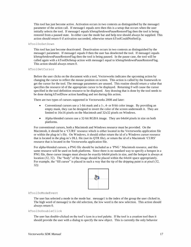
For alpha-blended cursors, a PNG file should be included as a ‘PNG ‘ Macintosh resource, and this
same resource will be used on both platforms. Since there is no standard way to specify a hotspot in a
PNG file, these cursor images must always be exactly 64x64 pixels in size, and the hotspot is always at
location (32, 32). The “body” of the image should be placed within the 64x64 space appropriately.
For example, the “fill cursor” is placed in such a way that the tip of the dripping paint is at pixel (32,
32):
kToolDoModeEvent
The user has selected a mode in the mode bar. message1 is the index of the group the user clicked in.
The high word of message2 is the old selection, the low word is the new selection. This action should
always return 0.
kToolDoDoubleClick
The user has double-clicked on the tool’s icon in a tool palette. If the tool is a creation tool then it
should provide the user with a dialog to specify the new object. This is currently the only behavior
Vectorworks SDK Manual 18
implemented in Vectorworks in response to this action. Expanding the meaning of this action should
be done with care. In particular, do not use it as an alternative interface to behavior for which
Vectorworks provides a standard for access (for example: do not bring up a preference dialog in
response to this action. Preferences should be accessed through a mode bar button).
Note that this is not the same as the new kToolDrawingDoubleClick action above.
kToolPointAdded
This action is called when the tool gets a mouse down in the content of the drawing. This action is also
called for a click drag mouse up. The tool may return 0, kToolCancel, kToolCompleted, or
kToolSwitchToCursor.
kToolPointRemoved
This action is called whenever the tool framework removes a tool point for any reason. Use this action
to clean up any state that becomes stale with the removal of a tool point. The tool may return 0,
kToolCancel, kToolCompleted, or kToolSwitchToCursor.
kToolDraw
This action is called when the tool needs to draw. The tool framework calls this draw action handling
expecting the tool to draw itself. Tools use the GS_GetToolPt APIs to determine the current state of
the tool and draw appropriately.
kToolHandleComplete
This action is called when the tool has signified, through a kToolGetStatus return value, that the tool is
complete. This is where the tool makes changes to the drawing. kToolHandleComplete action handling
is the most likely location for UNDO callbacks. The tool may return 0, kToolCancel, or
kToolSwitchToCursor.
kToolGetStatus
This action is called so the tool can return to the system the current state of the tool. A tool can return
the result of GS_OnePointToolStatus, GS_ClickDragToolStatus, GS_TwoPointToolStatus,
GS_ThreePointToolStatus, or GS_PolyToolStatus. In addition the tool can provide custom status
behavior by returning one of the following: kToolCompleted, kToolCollectingPoints, or
kToolWaitingForFirstPoint.
kToolMouseMove:
This action is called when the mouse moves over the content of the drawing. If the tool has the tool
definition resource screenBasedCursor flag set it gets kToolMouseMove action calls whenever the
mouse moves a pixel. If the tool does not set the screenBasedCursor flag, it gets called whenever the
smartcursor snaps to a new point.
kToolDrawingDoubleClick
This action is called whenever the user double-clicks in the content of the drawing window with two or
more Tool points. Tools do not handle this unless they wish to override the default behavior. The
default behavior is to switch to the cursor tool. Most tools that provide an override are multi-segment
tools that complete with double-click. The return value for kToolDrawingDoubleClick is one of
kToolCompleted, kHandledDocumentDoubleClick to override the default behavior. If
kToolCompleted is returned the tool’s kToolHandleComplete action handler will be called.
kToolOnCustomBarEvent
The tool has installed a custom bar using the GS_CustomBarInstall API. While the Custom Bar is
installed the tool will receive this action. Other APIs are provided to manage the custom databar. The
message1 parameter is a pointer to a CustomBarEventData structure.. See MiniCadHookIntf.h for a
description of these custom bar events.
kToolOnInitXProperties
Vectorworks SDK Manual 19
A workspace containing the plug-in has been loaded. This action is called following the
kToolInitGlobals action. This action allows the tool to install any additional extended properties using
the GS_SetToolProperty and GS_SetToolPropertyChar APIs. The message1 parameter contains the
CodeRefID for this tool’s definition procedure. This CodeRefID is needed for the
GS_SetToolProperty and GS_SetToolPropertyChar APIs. Some properties have associated actions.
See MiniCadHookIntf.h for a list of extended tool properties and any associated actions.
Tool Definition Resource: TDef
Every tool has a TDef resource of ID 128. Each of the fields of the TDef resource are described below:
disablePickUpdate
When set to true, the automatic updating of the Tool Pick Record is disabled. Normally, as the mouse
is moved over the document, Vectorworks automatically finds out what objects are near the mouse for
the kToolDoPick action. This may take a significant amount of time on large documents. Tools which
do not need this functionality, such as pure creation tools, should set this flag.
needsPlan
If a tool requires the current projection to be set to plan, set this flag.
needs3DProjection
If a tool requires a non-plan projection, set this flag.
uses3DCursor
Tools that operate using 3D grid and snapping points should set this flag.
screenBasedCursor
Activating this flag disables all gridding and snapping of the mouse when functions such as GetCoords
are called.
dontShowScreenHints
Tools for which the smart mouse screen hints are not useful can turn off the display of those messages
by setting this flag.
iconID
The iconID field indicates the resource ID of the icon to be displayed in the tool palette, which should
also be included in the resource file. (See “Tool Icon” below for information on including a PNG
format icon.)
defaultCursID;
If the Tool definition function returns 0 in response to a kToolDoPick message, then Vectorworks sets
the cursor to the one specified by defaultCursID.
messageStr
When the tool is selected (before the kToolDoSetup message has been passed to the definition
function) this string is set into the message bar.
waitMoveDist
For many tools, a good user interface allows a bit of “slop” before the tool actually takes effect. The
value of waitMoveDist is a distance in screen pixels that the mouse must move before Vectorworks
calls the tool definition function. If this distance is not exceeded before the tool click is finished, then
a selection tool is automatically made active.
constraintFlags
Vectorworks SDK Manual 20
This bit-field determines which cosntraints the user has available when the tool is active. Each bit
represents one of the constraints, with 1 indicating an available constraint. For the 10 current
constraints, adding together a combination of the following values will enable the appropriate
constraints:
1 Snap to Grid
2 Snap to Objects
4 Snap to Surface/Working Plane
8 Snap to Intersection
16 Snap to Distance
32 Constrain Parallel
64 Constrain Perpendicular
128 Constrain to Angle
256 Constrain Symmetrical
512 Constrain Tangent/to Working Plane Normal
For example, to activate only the Snap to Grid and the Snap to Intersection constraints, set
constraintFlags = 1+8 = 9.
Vectorworks tools generally fall into one of three “families” of constraint availability depending upon
which type of geometry the user is setting: points (locus tool), lines (segment tool, polygon tool), or
boxes (ellipse by rectangle tool and rectangle tool). One of these three sets of constraints flags often
contains the correct constraintFlags for new tools.
Min Version
This field holds the earliest version of Vectorworks that will properly run a plug-in. Each callback
contains the version of Vectorworks that first supported it, put the latest callback version in the Min
Version field.
Databar Mode
When the user clicks into the document, Vectorworks sets the Data Display Bar to the mode specified
in this field. The file MiniCadCallbacks.h lists the available constants. If the plug-in does not
need to change the Data Display Bar or needs to set a custom set of bars, set this field to 0.
Tool Icon
All Plug-in Tools should include an icon for the tool palette. For Vectorworks 2008 and later, the icon
must be 26 x 20 pixels, in PNG format, and should include an alpha channel. The contents of the PNG file
should be stored in a Macintosh resource with the resource type 'PNG ' (Note the ending space
character). The resource ID of the icon must be in the range 11000 – 14999, inclusive, and match the
corresponding field in the TDef resource.
The PNG file may be inserted into the Macintosh resource file using a resource editor. Alternatively, if you
use Rez to generate your resource file from a “.r” file, use can use the following command to include the
PNG file:
read 'PNG ' (11000, "Icon") "MyIcon.png";
Plug-in Tools may also include a traditional ‘ICN#’ and an ‘icl8’ resource to define the black-and-white
and 8-bit color icons. These old-style icons should be 32 x 32, but only the central 26 x 20 pixels will be
displayed.

Vectorworks SDK Manual 21
Tool Related Callbacks
Several callbacks support SDK Plug-in Tools and are documented in the FileMaker database “VW12 SDK
Library.fp5”.
Vectorworks SDK Manual 22
Plug-in Objects
Vectorworks supports another type of plug-in called a Plug-in Object. This feature provides a way to
deliver more powerful and easy to use objects. It will also make it possible for distributors and users to
create their own custom objects. A plug-in object will behave like a built-in object, and will draw itself
based on the current values of its parameters. Users can easily edit the parameter values using the Object
Info palette as they do with all Vectorworks objects.
When developing a Plug-in Object, you will actually need to develop two plug-ins: an object and either a
tool or menu. The associated Tool or Menu will be used to provide a user interface for the creation of the
Object. It may be as simple as a Tool which allows the user to click once in the drawing to place the
Object, or it may be a Menu Command that displays a complex series of dialogs which allow the user to
initialize the Object before it is created. The Plug-in Object’s code will not present a user interface. It will
simply draw the object based on the current parameter values. It will be called automatically by
Vectorworks whenever the object needs to be regenerated. This may be in response to the user changing a
parameter value on the Object Info palette for example.
Plug-in Object Types
There are several different types of Plug-in Objects. Each type supports different creation and editing
features. All types of Plug-in Objects contain a translation matrix that contains the location and rotation
angle for that object. The matrix also enables the developer to write the object’s code as if it were inside a
local coordinate space (i,j). For example, if the developer writes code to draw part of the object at (0,0),
then that is the origin of the object’s space, not the global space. Most object’s wont need to know where
in global space they are located, and won’t need to know if they are rotated. This will simplify the
developer’s task.
The object types are:
Point Plug-in Object
Linear Plug-in Object
Rectangular Plug-in Object
2D Path Plug-in Object
3D Path Plug-in Object
A Point Plug-in Object is typically created by asking the user to click once in the drawing to specify the
location point. A second click can be used to specify the rotation angle of the object. This is similar to the
way Symbols are inserted in Vectorworks. Once created, a Point object cannot be reshaped using the
cursor tool, only by changing its parameter values on the Object Info palette.
A Linear Plug-in Object has two points that define its geometry. It actually has a matrix and a special
length field. The first user-specified point is the origin of the matrix, and the second point is on the i-axis
of the matrix at a distance from the origin defined by the length field. The special length field is actually a
parameter named “LineLength” of type kFieldCoordDisp or 7. After a Linear object is created, the user
can reshape it using the cursor tool by clicking and dragging either endpoint.
A Rectangular Plug-in Object is similar to a linear object with an additional field. It has a “LineLength”
and “BoxWidth” field that define its shape. The origin will be at the midpoint of one side of the rectangle,
and the i-axis is along the center line. The rectangle is symmetrical about the i-axis, and therefore half of
the object will be drawn with positive “j” values, and half will be drawn with negative “j” values. A
Rectangular object will display eight handles when selected. These handle allow the user to graphically
reshape the object by dragging them.
Path Plug-in Objects contain a polyline or NURBS curve path object to help define their shape. The object
may be reshaped using the reshape tools, or the Object Info palette.
Vectorworks SDK Manual 23
Tool for Plug-in Object
A Tool that is associated with a Plug-in Object is the same as any other Tool developed with the SDK, with
a few exceptions. It will have an additional definition resource, and will call some Object-related
callbacks.
In the main( ) function, the tool should respond to the kToolHandleComplete action by calling the
GS_CreateCustomObject() callback. If this is the first object of this type to be created in a drawing, a
dialog is presented so the user can set default values for the parameters. Then a parametric object is created
in the drawing at the location specified.
If a preferences button is supported by the tool, then it should respond to the kToolDoModeEvent action
by calling the GS_DefineCustomObject() callback. This will present a dialog for the user to set
preferred default values for the parameters. These default values will be stored in the drawing file but no
object is created.
To support the double-click creation feature, respond to the kToolDoDoubleClick action by calling
GS_CreateCustomObjectDoubleClick().
In addition to the standard tool definition resource (‘TDef’ 128), a plug-in tool for plug-in objects must
contain another definition resource (‘PDEf’ 128). This resource specifies the name and version number of
the plug-in object. The Tool file and the Object Regeneration file must contain copies of the same ‘PDEf’
resource. The name is currently limited to 20 characters and must be unique within Vectorworks. The first
two characters of the name could be a prefix that identifies the developer. The prefix “GS” and is reserved
for use by Vectorworks. The version number is an integer in the range 0 to 32767. It can be used to
identify which version of a tool created an object in the drawing. You should increment the version number
if you change the number, type, or names of parameters (see “Parameter Definition” below). You may not
need to increment the version number if the only changes were made to the Regeneration algorithm.
As a developer, you should increment the version number of your plug-in objects as infrequently as
possible. There is no need to increment it during development, only if you change the object after you have
already shipped a version to users.
Plug-in Object Main Function
The Plug-in Object’s definition file defines both the behavior and data of a plug-in object. It defines the
behavior by implementing a definition procedure and specifies the parameters within a resource.
The prototype for an Object’s definition procedure is:
long plugin_main(long action, Handle parmHand, long message, long
&userData, CallBackPtr cbp)
The parameters to the definition procedure are:
action Identifies the task the tool needs to perform, and determines the significance of the
message parameter.
parmHand Handle to a Plug-in Object instance in drawing.
message The meaning of this parameter depends on the action. For example, with the
kParametricPreference action message is a Handle to the object’s Format node.
userData Four bytes of data that Vectorworks maintains for the plug-in between calls. This is
necessary because a plug-in cannot directly maintain its state. For example, the plug-in
may store a pointer to a C++ class here.
cbp Callback pointer needed to pass as first argument to Vectorworks callbacks.
Vectorworks SDK Manual 24
Plug-in Object Actions
The main function's action argument will be one of the following values:
kParametricInitGlobals
The application is launching. This action will not be called again until after
kParametricDisposeGlobals has been called. This is the plug-in's opportunity to initialize all
persistant data. The message parameter is unused. Return kParametricNoErr if initialization
succeeded, otherwise return kParametricSetupFailed.
kParametricDisposeGlobals
The application is quitting. The code should finalize all outstanding actions and free any allocated
resources. The message parameter is unused. This action should always return
kParametricNoErr.
kParametricRecalculate
A parameter value has been changed or the parametric object has been moved, rotated or changed in
some other way. Regenerate all drawing objects that define the look of this plug-in object based on the
current values for the parameters. This is the most important action for the regeneration file. The
message parameter is unused. Return kParametricNoErr or kParametricError.
kParametricPreference
This action gives the plug-in file an opportunity to pose a custom dialog so the user can set default
values for parameters or initialize an object that is about to be placed in the drawing. It is optional, and
if the Plug-in Object chooses not to present its own custom dialog then the Vectorworks application
will present a standard dialog.
A Plug-in Object may wish to present its own dialog if, for example, it needs to display a picture that
explains the meaning of each parameter graphically. If the plug-in regeneration file implements a
dialog, it should return kParametricPrefOK if the user hit the OK button and
kParametricPrefCancel if the user hit Cancel. (For compatibility with earlier versions of
Vectorworks, the Plug-in Object may also return kParametricNoErr meaning OK.)
If a Plug-in Object does not display its own dialog, it should return the constant
kParametricNotImplemented. In this case, a standard dialog will be provided by Vectorworks. Most
Plug-in Object will probably just allow Vectorworks to present the dialog.
Note that a Plug-in Object can ONLY show a dialog is response to this action. It should never present
a dialog or alert during any other action.
kObjOnInitXProperties
Plug-ins objects can specify extended properties. This action is called when the ‘Has Extended
Properties’ field of the ‘PXpr’ resource is set. The message parameter contains the CodeRefID for this
object’s definition pocedure. Use the CodeRefID and the GS_SetObjectProperty and
GS_SetObjectPropertyChar APIs to install extended object properties for the object. Some properties
have associated actions. See MiniCadHookIntf.h for a list of extended object properties and any
associated actions.
Vectorworks SDK Manual 25
Plug-in Object Resources
The regeneration file must contain a definition resource of type 'PDEf' with id 128 to specify the name and
version number of the object. The regeneration file and the tool file must both contain copies of the same
'PDEf' resource. The information within this resource is used to associate the tool file, regeneration file,
and Vectorworks object with each other. Filenames are not used for this purpose.
This custom resource and the others described below are defined by a template in the file “GSTMPL.rsrc”.
Note: The resource type 'PDEf' was introduced in Vectorworks 10 to replace the ‘PDef’ resource. It
includes an additional string so that the developer may specify both a universal name and localizable name
for a plug-in object. This improves international support. The old resource ‘PDef’ will continue to be
supported for a limited time.
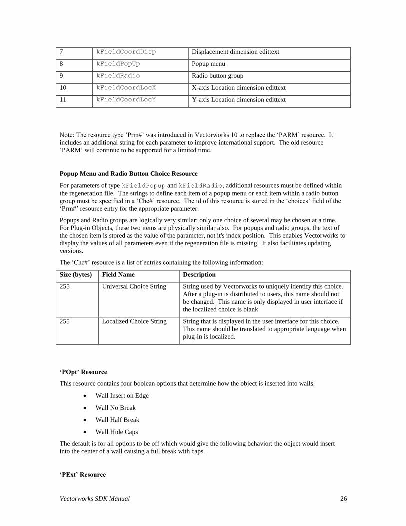
Plug-in Object Parameter Resource
Each parameter should be specified with a universal name, display name, type, and default value. This
information is specified in a ‘Prm#’ resource with id 128. It is a list of entries that consist of the following
information:
Parameter Resource Format (‘Prm#)
Size
(bytes)
Field Name Description
63 universal parameter
name
Name used by Vectorworks to uniquely identify this parameter.
After a plug-in is distributed to users, this name should not be
changed. This name is only displayed in user interface if the
localized parameter name is blank.
63 localized parameter
name
Name of parameter that is displayed in the user interface of
Vectorworks. This name should be translated to appropriate
language when plug-in is localized.
255 default value Default value of parameter in human-readable string format.
(Include units mark for dimension type parameters.)
1 type Type of parameter (see table below).
2 choices The id of a ‘Chc#’ resource containing list of choice strings for
popup menu or radio button parameters. (Only used for parameter
types 8 or 9.)
The parameter types are defined in MiniCadCallBacks.h and summarized in the following table:
Parameter Types
Type Constant User Interface Description
1 kFieldLongInt Integer number edittext
2 kFieldBoolean Checkbox
3 kFieldReal Real number edittext
4 kFieldText Edittext
5 kFieldCalculation N/A
6 kFieldHandle N/A
Vectorworks SDK Manual 26
7 kFieldCoordDisp Displacement dimension edittext
8 kFieldPopUp Popup menu
9 kFieldRadio Radio button group
10 kFieldCoordLocX X-axis Location dimension edittext
11 kFieldCoordLocY Y-axis Location dimension edittext
Note: The resource type ‘Prm#’ was introduced in Vectorworks 10 to replace the ‘PARM’ resource. It
includes an additional string for each parameter to improve international support. The old resource
‘PARM’ will continue to be supported for a limited time.
Popup Menu and Radio Button Choice Resource
For parameters of type kFieldPopup and kFieldRadio, additional resources must be defined within
the regeneration file. The strings to define each item of a popup menu or each item within a radio button
group must be specified in a ‘Chc#’ resource. The id of this resource is stored in the ‘choices’ field of the
‘Prm#’ resource entry for the appropriate parameter.
Popups and Radio groups are logically very similar: only one choice of several may be chosen at a time.
For Plug-in Objects, these two items are physically similar also. For popups and radio groups, the text of
the chosen item is stored as the value of the parameter, not it's index position. This enables Vectorworks to
display the values of all parameters even if the regeneration file is missing. It also facilitates updating
versions.
The ‘Chc#’ resource is a list of entries containing the following information:
Size (bytes) Field Name Description
255 Universal Choice String String used by Vectorworks to uniquely identify this choice.
After a plug-in is distributed to users, this name should not
be changed. This name is only displayed in user interface if
the localized choice is blank
255 Localized Choice String String that is displayed in the user interface for this choice.
This name should be translated to appropriate language when
plug-in is localized.
‘POpt’ Resource
This resource contains four boolean options that determine how the object is inserted into walls.
Wall Insert on Edge
Wall No Break
Wall Half Break
Wall Hide Caps
The default is for all options to be off which would give the following behavior: the object would insert
into the center of a wall causing a full break with caps.
‘PExt’ Resource
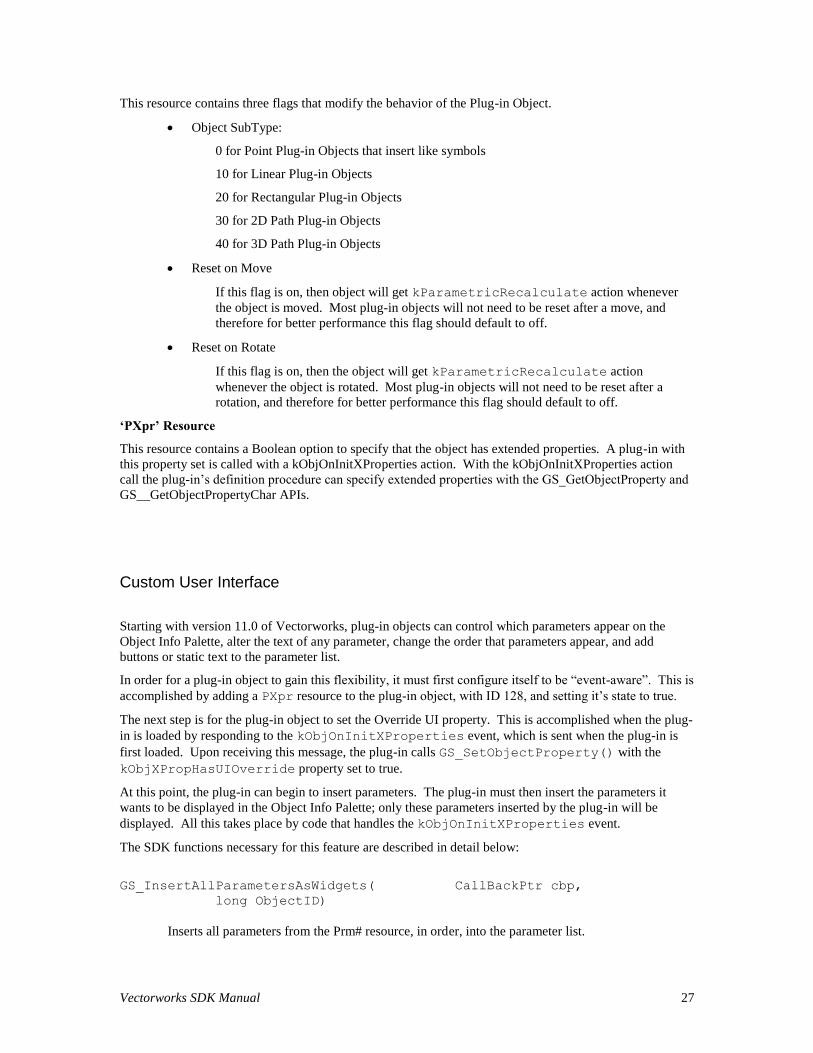
Vectorworks SDK Manual 27
This resource contains three flags that modify the behavior of the Plug-in Object.
Object SubType:
0 for Point Plug-in Objects that insert like symbols
10 for Linear Plug-in Objects
20 for Rectangular Plug-in Objects
30 for 2D Path Plug-in Objects
40 for 3D Path Plug-in Objects
Reset on Move
If this flag is on, then object will get kParametricRecalculate action whenever
the object is moved. Most plug-in objects will not need to be reset after a move, and
therefore for better performance this flag should default to off.
Reset on Rotate
If this flag is on, then the object will get kParametricRecalculate action
whenever the object is rotated. Most plug-in objects will not need to be reset after a
rotation, and therefore for better performance this flag should default to off.
‘PXpr’ Resource
This resource contains a Boolean option to specify that the object has extended properties. A plug-in with
this property set is called with a kObjOnInitXProperties action. With the kObjOnInitXProperties action
call the plug-in’s definition procedure can specify extended properties with the GS_GetObjectProperty and
GS__GetObjectPropertyChar APIs.
Custom User Interface
Starting with version 11.0 of Vectorworks, plug-in objects can control which parameters appear on the
Object Info Palette, alter the text of any parameter, change the order that parameters appear, and add
buttons or static text to the parameter list.
In order for a plug-in object to gain this flexibility, it must first configure itself to be “event-aware”. This is
accomplished by adding a PXpr resource to the plug-in object, with ID 128, and setting it’s state to true.
The next step is for the plug-in object to set the Override UI property. This is accomplished when the plug-
in is loaded by responding to the kObjOnInitXProperties event, which is sent when the plug-in is
first loaded. Upon receiving this message, the plug-in calls GS_SetObjectProperty() with the
kObjXPropHasUIOverride property set to true.
At this point, the plug-in can begin to insert parameters. The plug-in must then insert the parameters it
wants to be displayed in the Object Info Palette; only these parameters inserted by the plug-in will be
displayed. All this takes place by code that handles the kObjOnInitXProperties event.
The SDK functions necessary for this feature are described in detail below:
GS_InsertAllParametersAsWidgets( CallBackPtr cbp,
long ObjectID)
Inserts all parameters from the Prm# resource, in order, into the parameter list.

Vectorworks SDK Manual 28
cbp callback pointer
ObjectID ID of plug-in obtained from the message parameter
GS_AppendWidget( CallBackPtr cbp, long ObjectID,
int widgetType, int eventID,
ConstStr255Param text, long data)
Appends a widget to the end of the parameter list. This function is for use only with the new
parameter types introduced in Vectorworks 11, namely, the button and static text.
cbp callback pointer
ObjectID ID of plug-in obtained from the message parameter
widgetType One of the new widget types (12 = button, 13 = static text)
eventID Value that you would like Vectorworks to send in the message
parameter when that widget is clicked
text Associated text for that widget
data Reserved for future use
GS_InsertWidget( CallBackPtr cbp, long ObjectID,
int position, int widgetType, int eventID,
ConstStr255Param text, long data)
Inserts a widget into the parameter list at any point. This function is for use only with the new
parameter types introduced in Vectorworks 11, namely, the button and static text.
cbp callback pointer
ObjectID ID of plug-in obtained from the message parameter
position 0-based position at which this new widget will reside
widgetType One of the new widget types (12 = button, 13 = static text)
eventID Value that you would like Vectorworks to send in the message
parameter when that widget is clicked
text Associated text for that widget
data Reserved for future use
GS_InsertParameterWidget(CallBackPtr cbp, long ObjectID,
int position, int parameterID,
Constr255Param text, long data)
Inserts an existing parameter from the Prm# resource into the parameter list at any point. This
function is for use only with existing parameters in the Prm# resource.
cbp callback pointer
ObjectID ID of plug-in obtained from the message parameter
position 0-based position at which this new widget will reside
parameterID 1-based index of an actual plug-in parameter to insert (i.e., a parameter
defined in the Prm# resource)
text Associated text for that widget
data Reserved for future use
Vectorworks SDK Manual 29
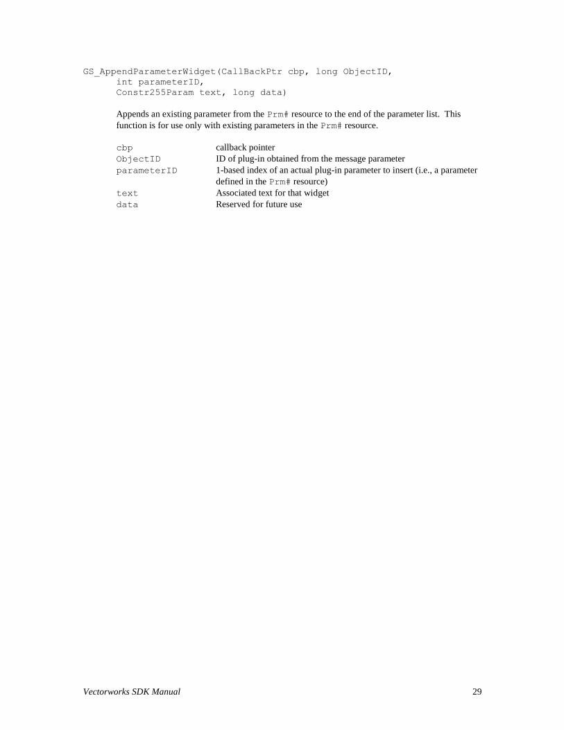
GS_AppendParameterWidget(CallBackPtr cbp, long ObjectID,
int parameterID,
Constr255Param text, long data)
Appends an existing parameter from the Prm# resource to the end of the parameter list. This
function is for use only with existing parameters in the Prm# resource.
cbp callback pointer
ObjectID ID of plug-in obtained from the message parameter
parameterID 1-based index of an actual plug-in parameter to insert (i.e., a parameter
defined in the Prm# resource)
text Associated text for that widget
data Reserved for future use
Vectorworks SDK Manual 30
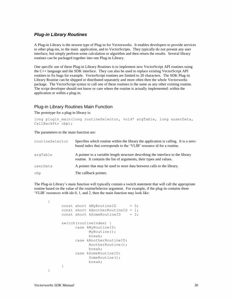
Plug-in Library Routines
A Plug-in Library is the newest type of Plug-in for Vectorworks. It enables developers to provide services
to other plug-ins, to the main application, and to VectorScripts. They typically do not present any user
interface, but simply perform some calculation or algorithm and then return the results. Several library
routines can be packaged together into one Plug-in Library.
One specific use of these Plug-in Library Routines is to implement new VectorScript API routines using
the C++ language and the SDK interface. They can also be used to replace existing VectorScript API
routines to fix bugs for example. VectorScript routines are limited to 20 characters. The SDK Plug-in
Library Routine can be shipped or distributed separately and more often then the whole Vectorworks
package. The VectorScript syntax to call one of these routines is the same as any other existing routine.
The script developer should not know or care where the routine is actually implemented: within the
application or within a plug-in.
Plug-in Library Routines Main Function
The prototype for a plug-in library is:
long plugin_main(long routineSelector, void* argTable, long &userData,
CallBackPtr cbp);
The parameters to the main function are:
routineSelector Specifies which routine within the library the application is calling. It is a zero-
based index that corresponds to the ‘VLIB’ resource id for a routine.
argTable A pointer to a variable length structure describing the interface to the library
routine. It contains the list of arguments, their types and values.
userData A pointer that may be used to store data between calls to the library.
cbp The callback pointer.
The Plug-in Library’s main function will typically contain a switch statement that will call the appropriate
routine based on the value of the routineSelector argument. For example, if the plug-in contains three
‘VLIB’ resources with ids 0, 1, and 2, then the main function may look like:
{
const short kMyRoutineID = 0;
const short kAnotherRoutineID = 1;
const short kSomeRoutineID = 2;
switch(routineIndex) {
case kMyRoutineID:
MyRoutine();
break;
case kAnotherRoutineID:
AnotherRoutine();
break;
case kSomeRoutineID:
SomeRoutine();
break;
}
}
Vectorworks SDK Manual 31
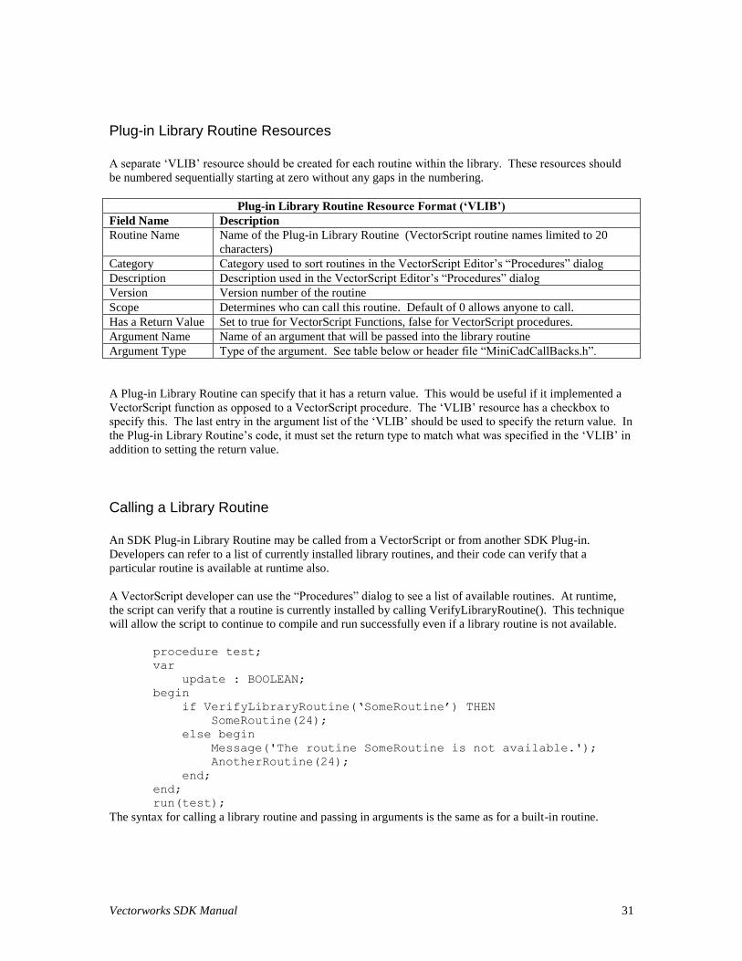
Plug-in Library Routine Resources
A separate ‘VLIB’ resource should be created for each routine within the library. These resources should
be numbered sequentially starting at zero without any gaps in the numbering.
Plug-in Library Routine Resource Format (‘VLIB’)
Field Name Description
Routine Name Name of the Plug-in Library Routine (VectorScript routine names limited to 20
characters)
Category Category used to sort routines in the VectorScript Editor’s “Procedures” dialog
Description Description used in the VectorScript Editor’s “Procedures” dialog
Version Version number of the routine
Scope Determines who can call this routine. Default of 0 allows anyone to call.
Has a Return Value Set to true for VectorScript Functions, false for VectorScript procedures.
Argument Name Name of an argument that will be passed into the library routine
Argument Type Type of the argument. See table below or header file “MiniCadCallBacks.h”.
A Plug-in Library Routine can specify that it has a return value. This would be useful if it implemented a
VectorScript function as opposed to a VectorScript procedure. The ‘VLIB’ resource has a checkbox to
specify this. The last entry in the argument list of the ‘VLIB’ should be used to specify the return value. In
the Plug-in Library Routine’s code, it must set the return type to match what was specified in the ‘VLIB’ in
addition to setting the return value.
Calling a Library Routine
An SDK Plug-in Library Routine may be called from a VectorScript or from another SDK Plug-in.
Developers can refer to a list of currently installed library routines, and their code can verify that a
particular routine is available at runtime also.
A VectorScript developer can use the “Procedures” dialog to see a list of available routines. At runtime,
the script can verify that a routine is currently installed by calling VerifyLibraryRoutine(). This technique
will allow the script to continue to compile and run successfully even if a library routine is not available.
procedure test;
var
update : BOOLEAN;
begin
if VerifyLibraryRoutine(‘SomeRoutine’) THEN
SomeRoutine(24);
else begin
Message('The routine SomeRoutine is not available.');
AnotherRoutine(24);
end;
end;
run(test);
The syntax for calling a library routine and passing in arguments is the same as for a built-in routine.
Vectorworks SDK Manual 32
An SDK developer can use the file “VWPluginLibraryRoutines.h” to see a list of all currently installed
library routines. This text file is written into the Plug-ins folder every time Vectorworks launches. An
SDK Plug-in can call GS_VerifyPluginLibrary() to determine at runtime if a library routine is available.
An SDK Plug-in must do a little extra work before calling a library routine however. It must build an
argument table to pass in.
PStr63 libRoutineName;
libRoutineName = "TestRoutine";
long status = 0;
// Allocate the argument table.
PluginLibraryArgTable* theArgs = new PluginLibraryArgTable;
// Setup arguments.
theArgs->args[0].argType = kPointArgType;
theArgs->args[0].ptValue = WorldPt(1,2);
theArgs->args[1].argType = kLongVarArgType;
theArgs->args[1].longValue = 345;
// Call it
wasCalled = GS_CallPluginLibrary(gCBP, libRoutineName, theArgs,
status);
if (wasCalled) {
// Get the return value and any pass-by-reference arguments
short myReturnValue = theArgs->functionResult.intValue;
long myLong = theArgs->args[1].longValue;
}
Memory Management and Other Options
Normally plug-in libraries are only loaded into memory when they are called and then they are unloaded
immediately afterward. This allows efficient use of memory by the Vectorworks application since libraries
that are never (or rarely) used do not consume resources. However, there may be circumstances where a
developer needs to override this behavior and control to some extent when their library is loaded.
Vectorworks provides a technique to address this situation.
When a plug-in library receives the kPluginLIBInitGlobals action, it can use the constant
kAddCodeReference to request that it remain loaded. The constant is a bit flag, so the OR operator should
be used to turn on a bit in the return value for the Plug-in Library. For example:
returnVal |= kAddCodeReference;
In the kPluginLIBDisposeGlobals action, the plug-in can use kReleaseCodeReference constant. Again the
constant is used with the OR operator since there may be other flags returned in this value also.
returnVal |= kReleaseCodeReference;
Another memory related option that Plug-in Libraries have is to determine how the userData argument is
used. By default, each routine within a library gets its own userData storage. If the library would like to
Vectorworks SDK Manual 33
share one userData among all routines within a library, then it can use the kUseSingleUserDataFlag
constant when preparing a return value for the kPluginLIBInitGlobals action. For example:
returnVal |= kUseSingleUserDataFlag;
When Vectorworks calls a Plug-in Library routine, the resource file associated with that plug-in is also
opened. If the library does not require any resources it can tell Vectorworks to leave the resource file
closed. The kDoNotOpenRsrcFileWithCallFlag constant can be used during the kPluginLIBInitGlobals
action. For example:
ReturnVal |= kDoNotOpenRsrcFileWithCallFlag;
Vectorworks SDK Manual 34
Section II: The Vectorworks Environment
Entities
The simplest element of the Vectorworks environment is the entity. Every entity has a type (found by
calling GetObjectType) which indicates what other properties it has, a position in a drawing list (found
by calling NextObject, PrevObject, and Parent), and an auxiliary list (described below). In
addition, some entities, called containers, also hold a sub-list of entities and can return the first and last
entities in that sub-list. Layers and Groups are examples of container entities.
Lists
Vectorworks uses two types of lists to hold drawing data, explicitly and non-explicitly terminated lists.
Explicitly terminated lists maintain a node at the very end of the list of the type termNode. This node is
used as both a signal of the end of the list and more importantly to store a reference back up the tree to the
list’s parent. Non-explicitly terminated lists do not have a special termination node, and the end of the list
is indicated by a nil reference in the last node’s next pointer. Because this type of list does not have a
terminal node, it is not possible to backtrack up the tree to the parent without maintaining a reference to the
parent yourself. All lists of drawing objects are explicitly terminated.
In addition to drawing object lists, there is another type of list, the auxiliary list. Aux lists provide for
supplementary data to be associated with an object (such as record data or cavity lines for a wall) that is
saved with the document. An aux list is an unsorted, non-explicitly terminated list that can be searched by
keys. Some records in an object’s aux list may have public interfaces, but most data in the aux lists is
private and should not be used.
As mentioned above, the aux list is unsorted which means that a plug-in should not assume the sequence of
nodes on that list. A plug-in should search the list for the node type it is interested in, and then verify that it
has found the correct node before using it.
Vectorworks defines a special type of aux object for use by plug-in developers, the userDataNode. It is an
aux object with a type of userDataNode and an internally maintained tag of type OSType that the plug-in
writer can use as a signature. To create a userDataNode, define a class or record that descends from
UserDataType (defined in MCCallBacks.h) or which contains a UserDataType object as the first
member. Either method will reserve the necessary space at the head of the structure for Vectorworks use.
Next, call NewDataObject, passing it the size and signature of your private DataNodeType. You now
have an aux object that can be safely used with the supplied aux lists callbacks. For convenience
FindDataNode has been supplied to simplify locating your private data objects.
Drawings
Vectorworks Document Structure and List Management

Vectorworks SDK Manual 35
The drawing list can be viewed as a tree. Its root is called the drawing header. The drawing header is a
container entity whose sub-list contains all the entities in the drawing. The first level of sub-objects in the
drawing header is layers. The drawing header is the only object that can contain layers, and it contains
every layer in the drawing. A layer contains all the entities that are on that layer, but not every entity on the
layer is in the layers sub-list. Some entities on the layer are contained within other entities on the layer. A
rectangle in a group on a layer is contained by both the group and the layer but only appears in the sub-list
of the group. Since the group is in the layer’s sub-list, however, the layer does indirectly contain the
rectangle.
The auxiliary list of the drawing header holds all the defining entities global to the document. These
include symbol definitions, record formats, worksheets, and command palettes.
List Traversal
Traversal is useful because it allows you to perform an operation on a set of drawing objects that meet
some criteria that you specify. For example you might want to:
Move all selected objects three inches to the left,
Resize all selected objects that are arcs of angles less than ten degrees to ten degree arcs,
Find every wall in the current layer and insert studs into the layer ‘<current> construction’
Vectorworks provides two methods to search the drawing list. The first and preferred method is through
the routine ForEachObject. ForEachObject can perform either a shallow or deep traversal, in
drawing order (back to front) starting from any point in the tree. If you use it to do a deep traversal from the
drawing header it will iterate over every object in the drawing. If, instead, you did a shallow traversal from
Vectorworks SDK Manual 36
the drawing header it would only return references to the layer objects in the drawing. ForEachObject
also takes as a parameter a selection clause that allows you to specify certain constraints that an object must
meet to be enumerated. This filtering is limited to the following attributes: is the object selected, editable, a
drawing object, or a symbol definition. The last criterion is a special case as symbol definitions are not in
the drawing tree, only symbol instances are. Symbol definitions are kept in a separate tree also rooted at
the drawing header. They are organized according to the same method drawing objects are (as symbols are
comprised of drawing objects). More information on the symbol definition list and symbol definitions can
be found in the section on Special Objects. Filtering based on other criteria must be hand coded.
ForEachObject works by calling a user supplied function once for every object it finds. The user-
supplied function must be of the type ForEachObjectProcPtr.
typedef void (*ForEachObjectProcPtr)(Handle h, CallBackPtr cbp, void
*env);
The argument “h” is a handle to the object ForEachObject found. cbp is a parameter used in
communicating between a plug-in and Vectorworks; it is discussed in detail in the section on the
Development Environment. env is a pointer to data supplied as a parameter to ForEachObject. It is
through env that the calling function can share data with the called function. See the tutorials for examples
of ForEachObject. It is one of the most important and frequently used functions Vectorworks
provides. It is also one of the more difficult to use correctly, so take time to study the examples.
The second method for traversing the drawing tree is through standard tree walking functions. Vectorworks
provides routines to move between siblings in the tree, NextObject and PrevObject; to move to the
parent of a node, ParentObject; and to move to the children of a node, FirstMemberObject and
LastMemberObject. Using these functions you can implement any type of tree walking algorithm.
This flexibility is more difficult to implement and manage than ForEachObject so it should only be
used when necessary.
Units
Before discussing some specific information about entities, an understanding of the different coordinate
spaces used by Vectorworks is important. Vectorworks defines and manages the space through coordinate
systems it imposes on it. The following are the basic coordinate systems:
Model
The units presented to the user. Vectorworks never expects these units as parameters and uses
them only for display of information to the user.
World
World space is the 3-dimensional Vectorworks universe. The vast majority of internal
Vectorworks calculations are performed in world space, and most of the SDK routines that refer to
object positions and distances are represented in world space.
World space values are represented by a double precision floating point data type. One world
coordinate currently represents one millimeter, but that relationship is not guaranteed to hold in
future versions of Vectorworks. See the bottom of this section for a description of constants and
functions that can be used to interpret and translate world space values.
Local
Some Vectorworks entities (symbol definitions, extrudes, multiple extrudes, sweeps, and layer
links) use simple entities to define their geometry and store these defining entities in local
coordinates. This coordinate system differs from world space only in the offset used to convert to
model space.
Vectorworks SDK Manual 37
View
This coordinate system is discussed only for completeness, and few situations require use of this
coordinate space. A 2D-only space which represents the viewable area of the document window,
this coordinate system is used only for drawing to the screen. The mapping from world space to
view space changes frequently so view space coordinates are usually useless for anything but
immediate drawing. If you wish to draw something to the screen, use the world space drawing
routines provided. The basic type of this system is the QuickDraw Point, which represents space
in pixels. As the coordinates in QuickDraw space are 16-bit values there is not a unique mapping
between world and screen space (many world space points map to the same view space point).
Page
This is a 2D-only coordinate system that represents the physical page the drawing is on. The basic
type is double and it’s always in inches. It is unaffected by any changes to scale or units.
Many functions exist to support translation from one coordinate system to another (usually to or from
world space). Some of the more widely-used space conversion functions follow:
GS_CoordLengthToPageLength() world space page space
GS_CoordLengthToPixelLength() world space view space
GS_CoordLengthToUnitsLength() world space current drawing units
GS_PageLengthToCoordLength() page space world space
GS_PixelLengthToCoordLength() view space world space
GS_UnitsLengthToCoordLength current drawing units world space
When writing to disk it’s a good idea to save coordinate values in a predefined real-world unit, like
millimeters or inches. Because it is not 100% guaranteed that world space will always be defined in
millimeters, the use of the following constants and callbacks are highly recommended:
kWorldCoordsPerInch
kWorldCoordsPerMM
GS_WorldCoordsPerDrawingUnit()
Similarly, when using world space constants in your code, you should not depend on one world space
coordinate being equivalent to one millimeter. Rather, if you wanted to add one millimeter to a world space
value, you should add the value kWorldCoordsPerMM.
Using these constructs above and a predefined real-world unit for values saved to disk will guarantee
reliable results for world space calculations from release to release.
Properties of Drawing Entities
In the last section, entities were discussed in relation to the drawing list. Drawing entities also have some
other common properties other than their position in the drawing hierarchy.
Graphic Attributes
Entities have the following attributes for which Vectorworks provides simple accessor and mutator
functions: name, class, lock state, color, fill pattern, pen pattern, line weight, visibility, and arrow
heads. Vectorworks also provides routines to get and set the default values of these attributes.
Defining Geometry
Vectorworks SDK Manual 38
All entities have a location in World space, but the method for storing the defining geometry differs for
each entity. You can determine an entity’s location by examining its bounding rectangle using
GetBox (which returns the smallest rectangle that completely surrounds the entity in the current view)
or GetCube (which returns the smallest cube that completely surrounds the entity). For many entities
(such as walls and groups), this rectangle or cube is a derived attribute, an attribute constructed from
the actual defining geometry of the entity. This distinction has subtle but important consequences
since some functions such as SetBox only have lasting effects on entities with defining rectangles
(such as rectangle and ellipses).
Special Objects
Vectorworks has entities of many different levels of complexity. These range from rectangles and line
segments, which have trivial defining properties to symbols and extrudes which hold information in local
coordinates systems which get transformed to their final location. This section explains some of the more
complicated entity types.
Symbols
There are two drawing entities related to symbols, symbol instances and symbol definitions. Symbol
definitions contain the entities that define the symbol and are stored in the aux list of the drawing header.
Symbol instances are markers that are placed in the drawing list specifying a transformation matrix and a
symbol definition to draw there.
Symbol Definitions
A symbol definition is very much like a Vectorworks group. The two distinguishing aspects are the local
coordinate system and their location in the drawing. Why do symbol definitions need a local coordinate
system? Groups do not need to use a local coordinate system because every instance of a group is unique.
You can copy and duplicate a group but that act creates a new and distinct instance of the group. Changes
to the new group do not affect the old group and vice versa. Because this is true, when you move a group
in the drawing you can directly change the coordinates of the component objects. Symbols, however, are a
shared object. If you change any component object in a symbol, all symbol instances will reflect that
change. To allow for the same symbol definition to be displayed at multiple locations, a local coordinate
system is used. In this method, all the component objects in a symbol are specified relative to the symbol’s
coordinate origin. When a symbol instance is made, the symbol’s component entities are drawn as if the
insertion point were the symbol’s local origin.
If you try to create a symbol from a group of objects on the drawing, that symbol’s insertion point will be
the World space origin. This will probably be the wrong effect if the collection of entities does not lie near
the World space origin. To deal with this, choose some World space point to be the symbol’s insertion
point. Then for each object you want to add to the symbol call MoveObject3D(myInsertionPoint). If
you are creating the objects in the symbol from scratch, you can create them about any arbitrary point and
then proceed as above or you can create them about the world origin.
Symbol Instances
Symbol Instances are fairly simple objects. They contain a transformation matrix and a symbol definition
reference. To draw the symbol instance, Vectorworks takes the geometry in the symbol definition and
multiplies it by the symbol instance’s matrix. Modification of the instance’s symbol definition is done by
calling GetDefinition and SetDefinition. Vectorworks also provides two creation routines for
adding new symbol instances to the drawing: PlaceSymbol and PlaceSymbolByName.
2D and 3D Symbols
Symbols have the additional complication of being hybrid entities, entities that can have both 2D and 3D
properties. Vectorworks stores both “halves” of the symbol in the same definition list, and then filters out
Vectorworks SDK Manual 39
entities as it processes the symbol for different operations. GetSymbolType can be called to quickly
check the type of a symbol.
The Symbol Library
Since symbol definitions do not directly appear in the drawing, they are not stored in the main portion of
the drawing list. Instead they are stored in their own list, which is found in the drawing header’s auxiliary
list. To get access to the symbol library you can call GetSymbolLibraryHeader and then traverse the
symbol library with the routines discussed in the drawing list section or you can use ForEachObject
specifying that you only want symbol definitions.
Walls
Walls are defined as a line segment with a variable number of “nodes”, called breaks, that lie along its
length. The controlling line, accessed with GetEndPoints, specifies the center line of the wall. The
width of the wall (GetWallWidth), indicates how far on each side of the center line to create the outer
edge of the wall. For 3D drawing, heights of the start and end of the wall (GetWallHeights) can be
independently set.
Breaks are modifications to the wall. An offset from the start point of the wall specifies their location.
Their type can be one of the following:
Cap
A Cap break specifies modifications to an end of the wall. A wall may have 0, 1 or 2 caps. The
offset of a cap break should be -1 if it is the start cap and LONG_MAX (defined in limits.h) if it is
the end cap. A cap specifies whether the end of the wall is closed and if it is closed whether it is
rounded. Since the position of the wall is specified by the center line, the cap also specifies any
offset of the endpoint of either side line from the corresponding end point of the center line (to
create a “tilted cap”). Vectorworks ignores cap end offsets with round caps.
Half
A half break is a gap in a side of a wall visible in plan view. These occur where one wall joins
another. A half break defines a starting position for the gap and a gap length.
Peak
A peak break is a 3D only break that specifies the height of the wall at a given offset.
Symbol
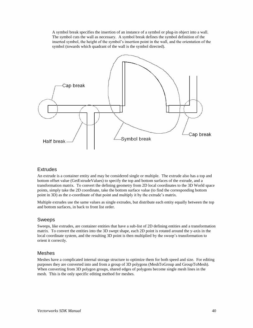
Vectorworks SDK Manual 40
A symbol break specifies the insertion of an instance of a symbol or plug-in object into a wall.
The symbol cuts the wall as necessary. A symbol break defines the symbol definition of the
inserted symbol, the height of the symbol’s insertion point in the wall, and the orientation of the
symbol (towards which quadrant of the wall is the symbol directed).
Extrudes
An extrude is a container entity and may be considered single or multiple. The extrude also has a top and
bottom offset value (GetExtrudeValues) to specify the top and bottom surfaces of the extrude, and a
transformation matrix. To convert the defining geometry from 2D local coordinates to the 3D World space
points, simply take the 2D coordinate, take the bottom surface value (to find the corresponding bottom
point in 3D) as the z-coordinate of that point and multiply it by the extrude’s matrix.
Multiple extrudes use the same values as single extrudes, but distribute each entity equally between the top
and bottom surfaces, in back to front list order.
Sweeps
Sweeps, like extrudes, are container entities that have a sub-list of 2D defining entities and a transformation
matrix. To convert the entities into the 3D swept shape, each 2D point is rotated around the y-axis in the
local coordinate system, and the resulting 3D point is then multiplied by the sweep’s transformation to
orient it correctly.
Meshes
Meshes have a complicated internal storage structure to optimize them for both speed and size. For editing
purposes they are converted into and from a group of 3D polygons (MeshToGroup and GroupToMesh).
When converting from 3D polygon groups, shared edges of polygons become single mesh lines in the
mesh. This is the only specific editing method for meshes.
Vectorworks SDK Manual 41
3D Views
A plug-in can specify a camera location and orientation with a TransformMatrix. The matrix can be
constructed and manipulated with the vector and matrix routines in the MCVector and MCMatrix libraries.
The matrix should transform 3D objects from world space to view space, which is then projected onto the
page according to the current projection. The projection plane (i.e. the screen) is defined to be the view
space x-y plane and the positive z extends toward the viewer (i.e. out of the screen).
Additional assumptions are made when the current projection is perspective. The viewer location is
considered to be the point (0, 0, perspectiveDistance) in view space. Objects are clipped to the view volume
which is that space extending from the viewer location toward the projection plane and enclosed by the
clipRect on that plane. Finally, all objects are clipped to the back clipping plane which is specified by z =
clipDistance in view space. The values of clipDistance, perspectiveDistance, and clipRect are obtained
from the GetPerspectiveInfo callback.
There is also a set of routines supporting interactive rotation of 3D objects. This is the behavior the user
sees when using 3D view specification tools like walkthrough and flyover. To use this service, first get the
current view matrix with GetViewMatrix. Then create a preview with PreviewSetup. You can then
repeatedly modify the matrix, call SetViewMatrix and call PreviewDrawFrame in a loop until the desired
view is chosen. The view change would typically respond to input from the user, but QuickTime export
uses the same calls to display animation previews. You must then call PreviewFinish, and if you want to
permanently alter the view, you must call NewCurrentViewMatrix to set the new view.
Vectorworks SDK Manual 42
Undo
Vectorworks supports undo and redo for multiple user actions. Generally, any operation that changes one
or more objects in a Vectorworks document must be accompanied by supporting undo code, or the
document could become corrupt. This guide lists the undo calls that are available to an SDK developer, and
describes how those calls should be used to ensure that document changes that are the result of an SDK
plug-in are properly communicated to the undo system.
Terminology
A separate undo table exists for each open document in Vectorworks. Each user action is represented in the
undo table as an undo event. Each undo event is composed of zero or more undo primitives.
The primary undo primitive available to SDK developers is called a swap primitive. It is so named because
it saves a before and after copy of an object, and swaps the two (one into the drawing, one out of the
drawing) when an undo or redo is performed.
Interface
The following callbacks are available to SDK developers: void GS_SetUndoMethod(CallBackPtr cbp, short newEvent);
void GS_NameUndoEvent(CallBackPtr cbp, ConstStr31Param eventName);
void GS_EndUndoEvent(CallBackPtr cbp);
Boolean GS_NonUndoableActionOK(CallBackPtr cbp);
Boolean GS_AddBeforeSwapObject(CallBackPtr cbp, BlankHandle h);
Boolean GS_AddAfterSwapObject(CallBackPtr cbp, BlankHandle h);
Boolean GS_AddBothSwapObject(CallBackPtr cbp, BlankHandle h);
Boolean GS_AddBeforeMoveObject(CallBackPtr cbp, BlankHandle h);
Boolean GS_AddAfterMoveObject(CallBackPtr cbp, BlankHandle h);
Boolean GS_AddCoordMoveObj2D(CallBackPtr cbp, BlankHandle h, WorldPt
delta);
Boolean GS_AddCoordMoveObj3D(CallBackPtr cbp, BlankHandle h,
WorldPt3 delta);
void GS_SupportUndoAndRemove(CallBackPtr cbp);
void GS_UndoAndRemove(CallBackPtr cbp);
Starting an Undo Event
The first step in handling undo in an SDK plug-in is to issue a GS_SetUndoMethod() call. This routine
must be called in every SDK plug-in, regardless of whether the actions of the plug-in are undoable or not.
The supported parameter values for this call are:
Parameter Constant Meaning
kUndoNone 0 The actions in this plug-in are not undoable.
kUndoSwapObjects 21 The actions in this plug-in are undoable.
kUndoReplaceSelection 17 The actions in this plug-in are undoable, and this
new event is to be pre-populated with swap
primitives for all currently selected objects (this
should only be used for object modifications, not
object deletions).
For example, if an SDK plug-in’s complete functionality consisted of doubling the size of all selected
objects, then the following call could be issued to handle that activity for undo:
GS_SetUndoMethod(cbp, kUndoReplaceSelection);
This call is typically placed in the kMenuDoInterface, kToolComplete, and kParametricRecalculate actions
of the plug-in Menu, Tool and Object respectively.
Vectorworks SDK Manual 43
Naming an Undo Event
When the user chooses undo or redo, a message is displayed on the mode bar describing the action that was
performed. The GS_NameUndoEvent() callback is used to specify the name that is attached to a plug-in
event. If an event is not explicitly named using the GS_NameUndoEvent() call, a generic event name is
used by default.
Event names are limited to 31 characters. To be consistent with internal Vectorworks event names, all
words should be capitalized and have the format "Verb [[Adjective] Noun]". Some examples that fit this
format are "Drag", "Delete Symbol", and "Create Rounded Rectangle". Some examples that do not fit this
format are: "Symbol creation dialog", "dimension tool", and "Stair Creation".
Building an Undo Event
Since the undo system is handle-based, it is important to remember that all SDK plug-ins that support undo
must communicate all object changes to the undo system using the appropriate undo calls. If any changes to
the drawing are not reflected in the undo table (especially object deletions), an application crash will likely
result.
Most changes to the drawing can be logged to the undo system using swap primitives. Swap primitives
handle the four basic operations that can be applied to Vectorworks objects:
1.Creating an object
2.Modifying and object
3.Deleting an object
4.Moving an object
The following five swap primitive types exist to handle the four object operations listed above:
Object Action Callback
Before an object is deleted Boolean GS_AddBeforeSwapObject(CallBackPtr cbp,
BlankHandle h);
Before an object is
modified
Boolean GS_AddBothSwapObject(CallBackPtr cbp,
BlankHandle h);
After an object is inserted Boolean GS_AddAfterSwapObject(CallBackPtr cbp,
BlankHandle h);
Before an object is moved Boolean GS_AddBeforeMoveObject(CallBackPtr cbp,
BlankHandle h);
After an object is moved Boolean GS_AddAfterMoveObject(CallBackPtr cbp,
BlankHandle h);
The last two swap primitives in the table above (GS_AddBeforeMoveObject() and
GS_AddAfterMoveObject()) must be used in pairs, and are used for moving objects within the internal
Vectorworks list data structure (for example, changing an object’s layer or using the "send to back"
command). For moving an object with respect to the page (changing its world coordinate values),
GS_AddCoordMoveObj2D() or GS_AddCoordMoveObj3D should be used.
While a GS_AddBothSwapObject() call can be used for an object that is being moved within the drawing
(i.e. an object whose world coordinate values are being changed), two more streamlined calls may also be
used for this type of action: GS_AddCoordMoveObj2D() and GS_AddCoordMoveObj3D(). While either
approach is valid for moving objects within the drawing, the CoordMove calls are faster and require less
memory.
In addition to swap and move primitives, other undo primitives also exist within the main Vectorworks
code to handle changes to the drawing that cannot be handled by swap primitives (such as changing
Vectorworks SDK Manual 44
preferences or adding classes). These undo primitives are added to the undo event automatically by the
main program and do not need to be addressed by the SDK developer.
When creating swap primitives, only objects that are going to eventually reside in the drawing need to be
communicated to the undo system. It is therefore not necessary to log objects that are created for temporary
purposes. When deleting objects, it is important to note this distinction and use the appropriate parameters
in the GS_DeleteObject() call. For deleted objects that are going to be logged to the undo system, a
GS_AddBeforeSwapObject(cbp, h) should be called and followed by a GS_DeleteObject(cbp, h, true), with
the true parameter indicating that undo is active and the object should be saved in the undo table.
Conversely, for deleted objects that are temporary and therefore are not going to be logged to the undo
table, GS_AddBeforeSwapObject() should not be called, and the object should be deleted using
GS_DeleteObject(cbp, h, false), with the false parameter indicating that undo is not active for this object
and the object should actually be freed from memory.
It is important to note that all undo operation are deep operations; it is not necessary to add undo primitives
for child objects of a group if that group object has already been handled for undo. For example, if a given
plug-in creates a straight flight of stairs that results in a group of hundreds of line segments, only one swap
primitive (GS_AddAfterSwapObject()) needs to be created (for the new staircase group object).
There is one exception to the guidelines listed above: plug-ins whose sole purpose is to create custom
objects or custom object definitions do not need to handle swap primitive cases. Due to the complexity of
the custom object callbacks, those swap cases are handled by the main Vectorworks code. The custom
object callbacks that take care of their own swap primitives are: GS_DefineCustomObject(),
GS_CreateCustomObject(), GS_CreateCustomObjectByMatrix(),
GS_CreateCustomObjectByDoubleClick(), and CB_CreateCustomObjectPath().
Ending an Undo Event
When an event is explicitly "ended", the undo system saves the view and prepares for the next event. For
SDK plug-ins, Vectorworks automatically issues and GS_EndUndoEvent() call if the plug-in did not issue
one before it returned control to the main program. It is therefore generally not necessary for SDK
developers to use the GS_EndUndoEvent() callback.
Backing Out a Partially Built Event
Sometimes it cannot be determined that an operation is going to fail until until part of the operation has
already completed (and an undo event has already been partially constructed). The GS_UndoAndRemove()
call can be used in this situation to back out the changes that were already made (and logged to the undo
system). This call also removes the partially-built event from the undo table.
If an undo event may be backed out (i.e. may be aborted using a GS_UndoAndRemove() call), it must be
preceded by a GS_SupportUndoAndRemove() call. This call, issued before the GS_SetUndoMethod() call,
instructs the undo system to build (at least temporarily) the next event even if the undo system is suspended
or disabled. If the GS_SupportUndoAndRemove() call is not issued before a GS_UndoAndRemove(), and
the user has disabled the undo system by setting the maximum number of undos to zero, the event will not
be built and the undo system will be unable to back the unwanted changes out of the drawing.
Plug-ins That Do Not Support Undo
The following two callbacks should be used for each SDK plug-in that does not support undo:
Boolean GS_NonUndoableActionOK(cbp);
void GS_SetUndoMethod(cbp, kUndoNone);
Vectorworks SDK Manual 45
The new GS_NonUndoableActionOK() callback notifies the user that the action that is about to be
performed is not undoable and that the undo table is about to be cleared. This notification gives the user a
chance to cancel the operation. It is important to check the return value of this call and abort the operation
if so directed by the user.
If the user chooses to continue without undo, it is critical that a GS_SetUndoMethod(kUndoNone) be
issued before any changes are made to the drawing. If this call is not issued, the document will likely
become corrupt. When an non-undoable plug-in issues GS_SetUndoMethod(cbp, kUndoNone), the undo
table is cleared and the undo system is suspended. When control is returned to the main program, the undo
system is reactivated.
Debugging
Tracking down undo bugs can be difficult, because a table corruption may not become apparent until well
after the action that caused the corruption has occurred. Consider the case where a plug-in deletes an object
in the drawing without making a GS_AddBeforeSwapObj() call. If a previous undo event contains a
reference to that object, that event may not try to access the invalid handle until it is cleared from the table,
thereby delaying any indication of the corruption.
Two tactics that can aid in identifying these types of bugs are:
1. Verify that the problem is undo-related by disabling undo and checking if the problem persists.
(Undo is disabled by setting the "number of undos" to zero on the Vectorworks Preferences
Session Pane.)
2. Once a bug is confirmed to be undo-related, set the "number of undos" preference to a small
number (1 or 2). This will force recent undo events to be cleared out of the table more quickly and
thereby expose latent corruptions sooner.
Vectorworks SDK Manual 46
User Interface
Some plug-ins may need to present a user interface to display information or gather information from the
user. Developers should follow the guidelines below and only present a dialog when it is appropriate.
There are several techniques to implement a user interface within a plug-in.
The simplest user interface feature that plug-ins should support is Help Tags on Macintosh and Tool Tips
on Windows. This feature simply identifies the plug-in by name when the user hovers the cursor over the
tool icon or menu item. To support this, a plug-in should include a ‘TEXT’ resource with an id of 128.
Another simple user interface feature is the help string that appears in the mode bar adjacent to the mode
bar buttons for a tool. In response to a DoSetup action, a plug-in tool can read a string from it resources
and then call GS_SetHelpString to display this string. A complex tool, which gathers several points from
the user, can call GS_SetHelpString repeatedly with a different prompt for each click.
Guidelines
A Plug-in should follow these guidelines when presenting alerts or dialogs to the user:
A Plug-in Menu may only pose a dialog during its kMenuDoInterface action.
Plug-ins of all types should never pose a dialog during their respective “InitGlobals”,
“DisposeGlobals”, “DoSetup”, and “DoSetDown” actions.
A Plug-in Object should never pose a dialog during its kParametricRecalculate action. This action
is only for drawing sub-objects. In addition to being against the spirit of the
kParametricRecalculate action, it may also cause a problem for the user. For example, a drawing
contains hundreds of instances of a particular Plug-in Object, and some situation arises where
Vectorworks needs to reset them all. If that Plug-in breaks this rule and poses a dialog during the
reset action, then the user will be confronted with a series of hundreds of dialogs.
Alerts
Vectorworks provides some simple alerts through the following SDK calls:
GS_PostMinorNoteAlert
GS_PostMinorStopAlert
GS_PostNoteAlert
GS_PostStopAlert
GS_Confirm
Context Sensitive Help
To add help, the first step is to create the HTML files that will display them. Then, a place must be found to
store the help. The help can either be stored on a website, or locally in the VWHelp folder of Vectorworks.
To enable the connection between the Vectorworks help system and any new plug-ins, the
CreateElementList plug-in menu must be called. This exists in the plug-ins folder, but is not part of any
workspace. It must be added. The CreateElementList menu item updates a file contained in the VWHelp
folder, "HelpLookup.txt". Any new plug-ins and their data are added to this file. This file is essential to
the help system of Vectorworks. Inside, it contains six columns detailed below.
Column 1: This is the type of item it is. Right now there are three types, Tool, Menu and Special.
The spelling and case must match one of these three types.
Column 2: This is the name of the item. Vectorworks uses this as a delimiter to the next column.
For developers, it is an easy way to identify the item for which to provide help.
Column 3: This is a semi-unique identifier for the item. This identifier coupled with the data from
Vectorworks SDK Manual 47
column one lets the help system pick the right help.
Column 4: This is a context string that is used by Vectorworks' help system. Third party developers
need not concern themselves with this except that this column must minimally contain an asterisk,
"*".
Column 5: This is a topic string that is used by Vectorworks' help system. Again, third party
developers need not concern themselves with this. And this column must at least have an asterisk,
"*".
Column 6: This is a URL that third party developers can use to link help for the plug-in on that line
with the context help. This URL can be of the form http://www.ThirdPartyDeveloperSite.com/etc,
or vwhelp://folderOrFileName… for files or folders that are contained within the VWHelp folder.
Column 6 must contain a URL and columns 4 and 5 must contain asterisks. Once this file has been altered
to contain a row for the new plug-in, the help system will be able to display help on the plug-in in the same
manner that Vectorworks displays other context-sensitive help.
Vectorworks SDK Manual 48
Layout Manager – Cross-Platform Dialogs
The Layout Manager is the recommended way to implement dialogs for SDK Plug-ins. It allows you to
define a user interface once using the cross-platform VectorScript syntax and then ask Vectorworks to
create and display your dialog for you. Vectorworks will display a dialog on each platform that looks
appropriate for that platform. It will automatically adjust the position of dialog items based on the current
font size. Vectorworks encourages SDK developers to use this method for implementing a user interface.
The Layout Manager system consists of two phases: dialog creation, and dialog management.
SDK developers should specify the dialog using VectorScript in a Macintosh ‘TEXT’ resource and manage
the dialog with the SDK API.
The complete layout manager API is available in both the C++ SDK and in VectorScript, which means
there are several ways to use the layout manager. The technique used here is the most common.
Creating Dialogs
To create a Layout Manager dialog write a VectorScript routine that: 1) creates the layout and the controls;
2) arranges the controls inside the layout; 3) adds any special alignments.
The first step is to create a Layout, which is equivalent to a dialog and serves as the overall container. Next,
create the individual controls and give each control a unique ID number between 3 and 400. ID’s 1 and 2
are reserved for the OK and Cancel button. Some controls require a size that is specified in character units,
which is based on the average size of a character in the current dialog font.
After creating the control, set the help text for individual controls using SetHelpString.
The Layout Manager supports several types of user interface items (sometimes referred to as “controls” or
“widgets”):
Checkbox
Combo Box (Popup menu)
Static Text
Editable Text
Multiline Editable Text
Help Description
List (Text only)
Real Number
Picture
Icon
Push Button
Radio Button
Slider Control
System Color Palette Button
Group Box
Tab Control
Swap Control
Checkbox Group Box
Radio Button Group Box
List Browser
Marker Attribute Button (Popup menu)
Line Style Button (Popup menu)
Line Weight Button (Popup menu)
Vectorworks SDK Manual 49
Line Attribute Button (combined line style and line weight) (Popup menu)
Pattern attribute Button (Popup menu)
Arranging controls
Positioning dialog controls is generally a two step process, where an initial arrangement specifies the
relative position of each control and then any special alignments are specified.
Dialogs items are arranged by setting an initial anchor control and then specifying a chain of controls
relative to the first control. Layouts and group items are the only two objects that can have anchor controls.
Anchor controls are set using either SetFirstLayoutItem or SetFirstGroupItem. The next item is placed
relative to the anchor item using either SetBelowItem or SetRightItem. Using these Set*Item calls, a chain
of controls can be created with each item relative to the other. Group items are just like other items in that
any control including another group can be placed to the right of or below another group.
The initial arrangement generally places items so that they’re left and top edges are aligned. To specify
other alignments use the AlignItemEdge call. In AlignItemEdge you specify an edge and an alignment
group. All objects in the same alignment group are aligned together. AlignItemEdge also allows you
specify whether you want an object to shift or resize when performing the alignment.
Managing Dialogs
To run a Layout Dialog that was specified using VectorScript in a ‘TEXT’ resource use the SDK call
GS_GetLayoutFromRsrc. This returns a dialog ID that you then pass to GS_RunLayoutDialog.
GS_RunLayoutDialog also takes an event handler function. The event handler is a function that is called
for each user event as well as for dialog set up and set down.
void MyHandleEvent(long dlogID, long& itemHit, void* data, void* env)
The event handler function has four parameters. The first parameter, dlogID, is passed in as a convenience
since all layout manager calls require a dialog ID. The second parameter, itemHit, specifies the ID of the
dialog control that received an event. The third parameter, data, is a pointer to a long that contains data
specific to the control and the event. For instance, if a checkbox is clicked on, the *data parameter will be
set to 1 or 0 to indicate the value of the checkbox. The fourth parameter is an optional environment variable
that can be used for passing data into the event handler function.
List Browser Event Handling
When handling events for list browsers, the data parameter in the event handler function contains
information about the event. To access the data parameter in the event loop, do the following:
long* liData = (long*)data;
Dereferencing liData (i.e. *liData) will give you the data value.
The list browser uses a zero-based index. *liData therefore can range from 0 to the number of rows – 1,
or the number of columns – 1. Note the data parameter can represent the column clicked or the row clicked
depending on what action was performed.
The user’s action is determined by a combination of the values of itemHit and *liData.
User action Values of itemHit and *liData
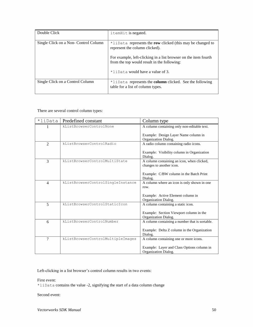
Vectorworks SDK Manual 50
Double Click
itemHit is negated.
Single Click on a Non- Control Column
*liData represents the row clicked (this may be changed to
represent the column clicked).
For example, left-clicking in a list browser on the item fourth
from the top would result in the following:
*liData would have a value of 3.
Single Click on a Control Column
*liData represents the column clicked. See the following
table for a list of column types.
There are several control column types:
*liData Predefined constant Column type 1 kListBrowserControlNone A column containing only non-editable text.
Example: Design Layer Name column in
Organization Dialog.
2 kListBrowserControlRadio A radio column containing radio icons.
Example: Visibility column in Organization
Dialog.
3 kListBrowserControlMultiState A column containing an icon, when clicked,
changes to another icon.
Example: C/BW column in the Batch Print
Dialog.
4 kListBrowserControlSingleInstance A column where an icon is only shown in one
row.
Example: Active Element column in
Organization Dialog.
5 kListBrowserControlStaticIcon A column containing a static icon.
Example: Section Viewport column in the
Organization Dialog.
6 kListBrowserControlNumber A column containing a number that is sortable.
Example: Delta Z column in the Organization
Dialog.
7 kListBrowserControlMultipleImages A column containing one or more icons.
Example: Layer and Class Options column in
Organization Dialog.
Left-clicking in a list browser’s control column results in two events:
First event:
*liData contains the value -2, signifying the start of a data column change
Second event:
Vectorworks SDK Manual 51
*liData contains a value equal to the column index where the click occurred.
Here is a sample function that processes these two events:
Boolean HandleColumnDataChangeMessage(long liItemHit, long liData)
{
Boolean bSuccess = true;
static Boolean sbReceivingColumnDataChangeMsg = false;
const int kColumnDataChangeMessageStart = -2;
if (liData == kColumnDataChangeMessageStart) {
sbReceivingColumnDataChangeMsg = true;
sbUpdateAllItems = false;
}
else {
if (sbReceivingColumnDataChangeMsg) {
if (liData != -1) {
sbReceivingColumnDataChangeMsg = false;
switch (liItemHit) {
case kListBrowser: {
// Process message
...
Note that you only get two messages regardless of how many items are selected for performance reasons.
If you are dealing with a multi-hundred layer list, you do not want to wait for multi-hundred messages in
order to process the click. You can use GS_IsListBrowserItemSelected within a loop to
determine which items need to process the click. Since the message is sent after the list browser data has
been changed, you can use functions such as GS_GetListBrowserItemInfo to check the new value
of the data column.
Platform-Specific User Interface
If the Plug-in requires an interface that is too complex to be represented with the Layout Manager, then it
should use other platform-specific techniques. A Plug-in may call the appropriate operating system API
calls directly to build and display a dialog. The platform-specific code will have to be developed separately
on the Mac and Windows, which increases the development and maintenance effort required. A Plug-in
may also use platform-specific application frameworks such as Metrowerks’ PowerPlant on the Mac and
Microsoft’s MFC on Windows. These frameworks are discussed in more detail in the section “The
Development Environment”.
Display of Numeric Values
When displaying numeric data to the user, it is important that the format of the numbers conform to the
user’s specifications, and where those are incomplete that they be consistent. For most needs, the
Vectorworks routines CoordToDimString and AngleToStringN will suffice. If you are working with non-
coordinate values, or floating point coordinate values, you may need to format the numbers yourself. To do
this you will need access to the users specifications for number display. This information is stored in a
UnitsType record (see MiniCadCallbacks.h).
struct UnitsType {
WorldCoord storedAccuracy; // WorldCoords/unit
Short format; // Display format
Vectorworks SDK Manual 52
double_gs unitsPerInch; // units/inch
Str7 unitMark; // Unit string
Long displayAccuracy; // Largest denominator
UnitFlagsType unitFlags; // Various flags
};
Note: World coordinates are centered on the world origin, which never moves. If the user has moved the
user origin, then you will need to offset world values by the user origin’s location in world space before
you display them. To get the user origin use GetUserOrigin.
Vectorworks SDK Manual 53
Section III: The Development Environment
Cross-Platform Development
The Vectorworks SDK enables development of plug-ins for both the Apple Macintosh and the Microsoft
Windows operating systems. A separate development environment is used on each platform to build a
plug-in for that particular platform. Depending on the specifics of the plug-in, some of the source code
may be shared between the two versions and some may be platform-specific.
Installing the Development Tools
Vectorworks recommends a specific version of the development tools to be used with a particular version
of the Vectorworks SDK. This may not always be the latest version of the development tools, but it will be
a version that is proven to work successfully with our SDK. If an older version is recommended, it can be
obtained from Apple, Microsoft and Metrowerks by registered users. Apple provides older versions of
their tools from their ADC site. Microsoft will provide older versions through their “downgrade” program
for a small fee. Call their fulfillment center at 1-800-360-7561. Metrowerks will provide an older version
of their tools free of charge, and can be reached at 1-800-377-5416.
For the Vectorworks 12.5 SDK, the supported development environment on the Mac is Xcode 2.2, and on
Windows it is Microsoft Visual Studio .NET 2003. See the release notes for the latest information.
Macintosh Project and Compiler Settings
A project file is used to identify the plug-in’s source code, and specify various compile and link options.
Xcode project file have filenames that end in “.xcodeproj”.
We recommend you start any plug-in from a sample or a template. If you decide not to, or you accidentally
change the settings in you project, compare your projects settings with those of the supplied sample
projects.
Windows Project and Compiler Settings
A project file in Visual Studio will have a “.vcproj” filename extension, and will describe how to build a
particular plug-in as a Dynamic Linked Library or DLL.
Vectorworks SDK Manual 54
Resources
Templates
Some of the Macintosh resources required by plug-ins are custom resources defined by Vectorworks
specifically for the Vectorworks SDK. The Macintosh resource editor, ResEdit, will not recognize these
custom resource types until it has access to the templates that describe the custom resources. The templates
are located in the file “GSTMPL.rsrc” which is in the “SDKLib:ToolsMac:” folder. Developers should
copy all the ‘TMPL’ templates from GSTMPL.rsrc and paste them into the “ResEdit Preferences” file
within the “System Folder:Preferences” folder. This will help ResEdit interpret these custom resources.
Macintosh Resources on Windows
A Windows Plug-in will use both Macintosh and Windows resources. The Macintosh resources describe
the definition and attributes of a plug-in as described in Section II of this manual. These resources will be
created and edited on a Macintosh and then “flattened” and copied to a Windows computer. The flattening
process simply reads the resource-fork of a Macintosh file and writes the data to the data-fork of a
Windows file. By convention, these flattened files have a filename extension of “.qtr”. There will be one
qtr file for each Windows plug-in file.
To “flatten” a resource file you can use a utility program like “QuickConvert” or simply copy the Mac file
to a PC-formatted floppy disk or zip disk. Move the disk to a PC. The flattened file will be in a Resources
directory on the disk.
Windows Resources on Windows
A Windows Plug-in may also contain Windows Resources. This is only required if the plug-in needs a
conventional (i.e. not alpha-blended) mouse cursor. See kToolGetCursor for more information.
Vectorworks SDK Manual 55
Debugging
To diagnose and fix problems with your plug-in, it is possible to debug it at the source level. You will be
able to set breakpoints, step through your plug-in’s source code line by line, break at watchpoints and many
other debugging features.
Debugging on Macintosh
Set up your project to launch Vectorworks from Xcode:
From the “Project” menu in Xcode, select “New Custom Executable…”. In the resulting Assistant dialog,
give the custom executable some name, provide the path to the host application (Vectorworks) and add it to
your project. You will be able to set break points inside your plug-in and you can click “Build and Debug”.
Debugging on Windows
Set up your project to launch Vectorworks from Visual Studio .NET:
From the Solution Explorer in Visual Studio .NET, right-click on your project’s name, and select Properties
at the bottom of the resulting pop-up menu. This brings up the Property Pages dialog for your project.
Click the Debugging label in the Configuration Properties pane (on the left). In the right pane, under the
Action section, select the Command property, and enter the path to the host application (Vectorworks).
(Instead of typing in the path to Vectorworks, you can click the triangle at the right of this edit box, and
select Browse in order to browse to Vectorworks’ location.)
Set the value of the Working Directory property to the full file path to Vectorworks. (Again, you can click
on the “…” box at the right of this edit box to browse to Vectorworks’ directory, rather than typing it in.)
The value of the Attach property should be No.
Click OK.
Now you can start Vectorworks by selecting Debug | Start.
As an alternate approach, if Vectorworks is already running, you can attach the debugger to the executing
Vectorworks process. To do so, select the Debug | Processes… menu item, find Vectorworks in the
“Available Processes” list box, and click the Attach button.
Vectorworks SDK Manual 56
Application Frameworks
Plug-in developers are encouraged to structure their source code so that most (or all) of it is cross-platform,
and use the Layout Manager as a cross-platform way to display dialogs. This will increase productivity and
decrease maintenance required. However, some plug-ins may require a complex user interface that Layout
Manager does not support. The plug-in may also like to take advantage of some other feature of an
application framework. In this case, the plug-in’s code can be factored into two platform-specific user
interface sections, and one cross-platform section. These techniques are really beyond the scope of the
Vectorworks SDK, but this chapter will provide a few tips for those who choose to use them. Again, the
use of these frameworks is optional.
Two common platform-specific application frameworks are Metrowerks’ PowerPlant on the Macintosh and
Microsoft’s MFC on Windows. These frameworks are included with each of the development
environments: CodeWarrior and Visual Studio .NET.
Vectorworks SDK Manual 57
Section IV: VCOM – Vectorworks Component Object Model
What is VCOM
VCOM (Vectorworks Component Object Model) is a API to deliver component services in the
Vectorworks runtime.
Component services are provided by the main application or any installed plug-in libraries. Providers
register services with the VCOM manager using interface identifiers. Clients then obtain access to the
registered services in the form of a pointer to a class of virtual functions. Every plug-in can obtain access to
an interface without knowing which is the concrete provider.
Client: using VCOM
VCOM is part of the SDK which allow the plug-ins to use interfaces (be clients) or to provide interfaces
(be providers).
In order a plug-in to be able to use VCOM it needs to initialize it with call to ‘GS_InitializeVCOM’ placed
in plug-ins main function:
long MenuMain(long action, long message1, long& userData)
{
// initialize VCOM mechanizm
::GS_InitializeVCOM( gCBP );
// ...
}
After initialization the plug-in could query for interface with call to ‘GS_VWQueryInterface’ to obtain a
pointer to that interface implementation.
VCOM recognizes the interfaces by their VWIID which is Universally Unique Identifiers (UUID) Every
interface that could be queried which Vectorworks provides has its VWIID. This is a constant defined in
the file where the interface is defined. The constants are prefixed with ‘IID_’ and the name of the interface.
Here is a same of a plug-in that queries interface:
IVCOMSample* pSampleInst = NULL;
if ( VCOM_SUCCEEDED( ::GS_VWQueryInterface(
IID_VCOMSample,
(IVWUnknown**) & pSampleInst ) ) )
{
VCOMError vcomErr = pSampleInst->Function();
pSampleInst->Release();
}
In this example ‘IID_VCOMSample’ is the VWIID constant that identifies the ‘IVCOMSample’ interface.
Note! You mush always release queried interfaces.
For easier use there is VCOMPtr template class that allows you to query and automatically release
interfaces:
template<class T> class VCOMPtr
{
public:
Vectorworks SDK Manual 58
VCOMPtr();
VCOMPtr(T* ptr);
VCOMPtr(const VWIID& iid);
VCOMPtr(const VCOMPtr& p);
~VCOMPtr();
VCOMPtr& operator=(const VCOMPtr& p);
T* operator->() { return fPtr; }
T** operator&() { return & fPtr; }
operator T*() { return fPtr; }
private:
T* fPtr;
};
- VCOMPtr(const VWIID& iid) creates auto-pointer for new instance for the specified identifier;
- VCOMPtr(T* ptr> creates auto-ointer for existing interface pointer;
- VCOMPtr(const VCOMPtr& p) will create auto-pointer for existing auto-pointer;
And here is example of using it:
// this queries the interface
// the interface instance
// will be autmatically released
VCOMPtr<IVCOMSample> pSampleInit( IID_VCOMSample );
// determine if it contains
// valid interface pointer
if ( pSampleInit ) {
// call function from the interface
VCOMError vcomErr = pSampleInit->Function();
}
By definition each function for an interface returns 'VCOMError' state. This state denotes if the function
succeeded. To determine if the function succeeded or failed there are macros 'VCOM_SUCCEEDED' to
determine success and 'VCOM_FAILED' to determine failure.
The predefined common VCOM errors are:
- kVCOMError_NoError - There was no error.
- kVCOMError_Failed - The operation failed due to problem within the called function.
- kVCOMError_OutOfMemory - Out of memory.
- kVCOMError_NotInitialized - Either VCOM or the object are not initialized properly.
- kVCOMError_NoInterface - There is no interface with desired VWIID.
- kVCOMError_NotImplemented - The function called is not implemented.
- kVCOMError_DuplicateIID - Duplicate VWIID when registering interface.
Vectorworks SDK Manual 59
- kVCOMError_NoModule - No module containing the interface.
- kVCOMError_NoInstance - No instance for the VWIID.
- kVCOMError_Unexpected - Unexpected error.
- kVCOMError_InvalidArg - Some of the parameters for the call are not valid (NULLs or bad
values)
Provider: Making interface provider
Provider of interfaces can be only Vectorworks library plug-ins. They must initialize VCOM with
'GS_InitializeVCOM' at the beginning of the main function. This library plug-in should handle three
additional messages responsible for registering, allocating and freeing the interfaces:
kVCOMRegisterInterfaces - This message is sent to the library plug-in so it will be able to
register (GS_VWRegisterInterface) the interfaces that this plug-in supports. This is done on
Vectorworks initialize time, and with it's help Vectorworks knows which plug-in what set of
interfaces supports;
kVCOMQueryInterface - This message is sent whenever an interface instance must be allocated.
When a client queries instance of an interface (through 'GS_VWQueryInterface' call) this message
is sent to appropreate plug-in that supports the interface;
kVCOMReleaseInterface - This message is sent when an interface instance should be deleted
(it's no longer used)
Here is example of an interface provider (\Sample\VCOMProviderLibrary)
long PluginLibraryMain(long routineSelector, void* argTable, long
&ioUserData)
{
// initialize VCOM mechanizm
::GS_InitializeVCOM( gCBP );
long reply = 0L;
switch (routineSelector) {
case kPluginLIBInitGlobals:
break;
case kPluginLIBDisposeGlobals:
break;
// -----------------------------------------------------------
// VCOM support
case kVCOMRegisterInterfaces: {
// register the putblic interface
::GS_VWRegisterInterface( IID_VCOMSample, argTable );
reply = kVCOMError_NoError;
} break;
// handle creation of interfaces of this library
case kVCOMQueryInterface: {
VWIID* pIID = (VWIID*) argTable;
IVWUnknown* pInterface = 0;
if ( pIID == NULL ) {
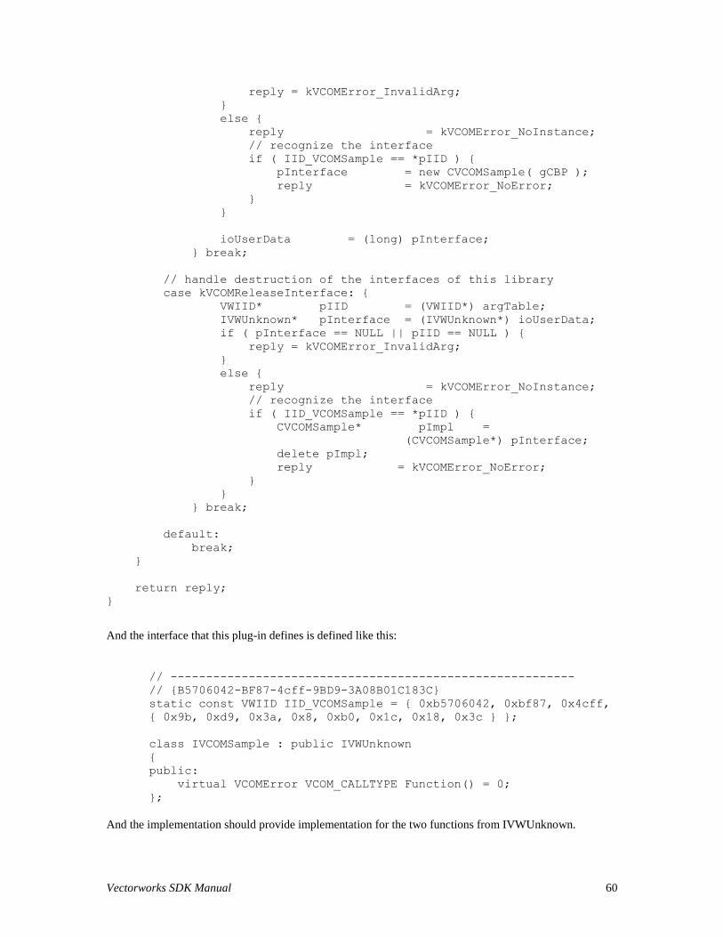
Vectorworks SDK Manual 60
reply = kVCOMError_InvalidArg;
}
else {
reply = kVCOMError_NoInstance;
// recognize the interface
if ( IID_VCOMSample == *pIID ) {
pInterface = new CVCOMSample( gCBP );
reply = kVCOMError_NoError;
}
}
ioUserData = (long) pInterface;
} break;
// handle destruction of the interfaces of this library
case kVCOMReleaseInterface: {
VWIID* pIID = (VWIID*) argTable;
IVWUnknown* pInterface = (IVWUnknown*) ioUserData;
if ( pInterface == NULL || pIID == NULL ) {
reply = kVCOMError_InvalidArg;
}
else {
reply = kVCOMError_NoInstance;
// recognize the interface
if ( IID_VCOMSample == *pIID ) {
CVCOMSample* pImpl =
(CVCOMSample*) pInterface;
delete pImpl;
reply = kVCOMError_NoError;
}
}
} break;
default:
break;
}
return reply;
}
And the interface that this plug-in defines is defined like this:
// ---------------------------------------------------------
// {B5706042-BF87-4cff-9BD9-3A08B01C183C}
static const VWIID IID_VCOMSample = { 0xb5706042, 0xbf87, 0x4cff,
{ 0x9b, 0xd9, 0x3a, 0x8, 0xb0, 0x1c, 0x18, 0x3c } };
class IVCOMSample : public IVWUnknown
{
public:
virtual VCOMError VCOM_CALLTYPE Function() = 0;
};
And the implementation should provide implementation for the two functions from IVWUnknown.
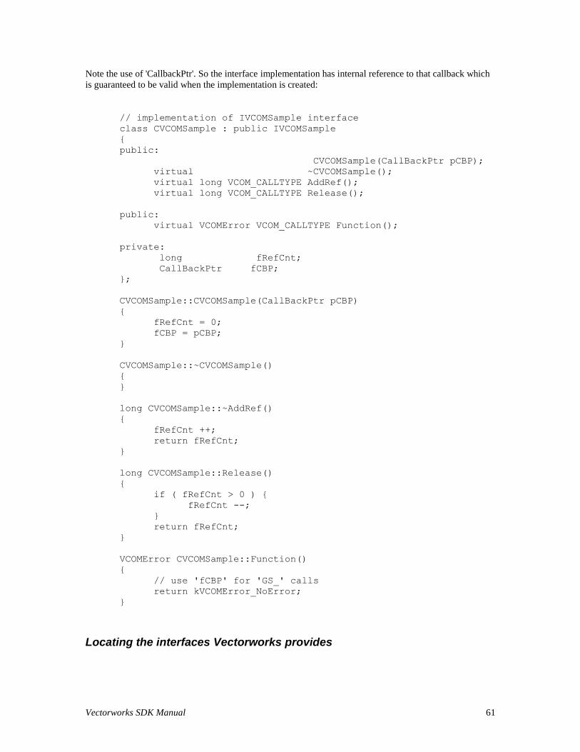
Vectorworks SDK Manual 61
Note the use of 'CallbackPtr'. So the interface implementation has internal reference to that callback which
is guaranteed to be valid when the implementation is created:
// implementation of IVCOMSample interface
class CVCOMSample : public IVCOMSample
{
public:
CVCOMSample(CallBackPtr pCBP);
virtual ~CVCOMSample();
virtual long VCOM_CALLTYPE AddRef();
virtual long VCOM_CALLTYPE Release();
public:
virtual VCOMError VCOM_CALLTYPE Function();
private:
long fRefCnt;
CallBackPtr fCBP;
};
CVCOMSample::CVCOMSample(CallBackPtr pCBP)
{
fRefCnt = 0;
fCBP = pCBP;
}
CVCOMSample::~CVCOMSample()
{
}
long CVCOMSample::~AddRef()
{
fRefCnt ++;
return fRefCnt;
}
long CVCOMSample::Release()
{
if ( fRefCnt > 0 ) {
fRefCnt --;
}
return fRefCnt;
}
VCOMError CVCOMSample::Function()
{
// use 'fCBP' for 'GS_' calls
return kVCOMError_NoError;
}
Locating the interfaces Vectorworks provides
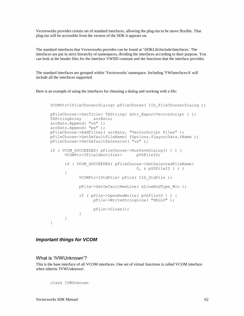
Vectorworks SDK Manual 62
Vectorworks provides certain set of standard interfaces, allowing the plug-ins to be move flexible. That
plug-ins will be accessible from the version of the SDK it appears on.
The standard interfaces that Vectorworks provides can be found at '\SDKLib\Include\Interfaces.' The
interfaces are put in strict hierarchy of namespaces, dividing the interfaces according to their purpose. You
can look at the header files for the interface VWIID constant and the functions that the interface provides.
The standard interfaces are grouped within 'Vectorworks' namespace. Including 'VWInterfaces.h' will
include all the interfaces supported.
Here is an example of using the interfaces for choosing a dialog and working with a file:
VCOMPtr<IFileChooserDialog> pFileChoose( IID_FileChooserDialog );
pFileChoose->SetTitle( TXString( kStr_ExportVectorScript ) );
TXStringArray arrExts;
arrExts.Append( "vs" );
arrExts.Append( "px" );
pFileChoose->AddFilter( arrExts, "VectorScript Files" );
pFileChoose->SetDefaultFileName( fOptions.fLayoutData.fName );
pFileChoose->SetDefaultExtension( "vs" );
if ( VCOM_SUCCEEDED( pFileChoose->RunSaveDialog() ) ) {
VCOMPtr<IFileIdentifier> pVSFileID;
if ( VCOM_SUCCEEDED( pFileChoose->GetSelectedFileName(
0, & pVSFileID ) ) )
{
VCOMPtr<IStdFile> pFile( IID_StdFile );
pFile->SetDefaultNewLine( kLineEndType_Win );
if ( pFile->OpenNewWrite( pVSFileID ) ) {
pFile->WriteStringLine( "HELLO" );
pFile->Close();
}
}
}
Important things for VCOM
What is ‘IVWUnknown’?
This is the base interface of all VCOM interfaces. One set of virtual functions is called VCOM interface
when inherits 'IVWUnknown'.
class IVWUnknown
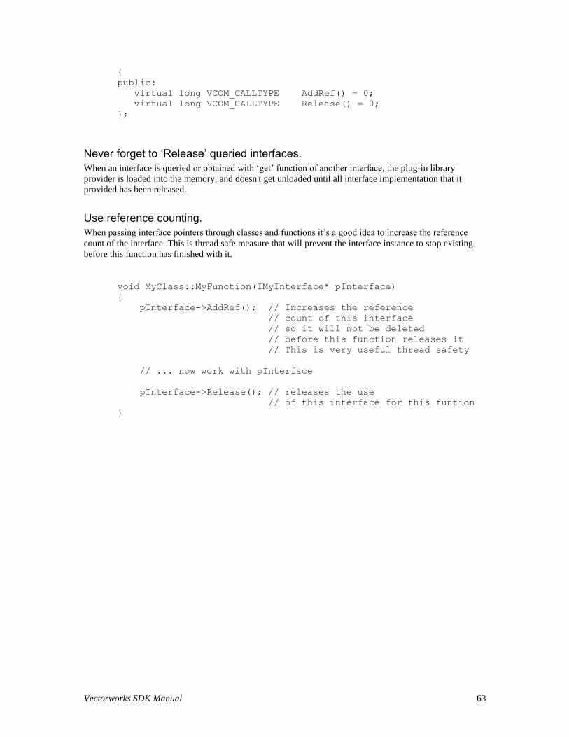
Vectorworks SDK Manual 63
{
public:
virtual long VCOM_CALLTYPE AddRef() = 0;
virtual long VCOM_CALLTYPE Release() = 0;
};
Never forget to ‘Release’ queried interfaces.
When an interface is queried or obtained with ‘get’ function of another interface, the plug-in library
provider is loaded into the memory, and doesn't get unloaded until all interface implementation that it
provided has been released.
Use reference counting.
When passing interface pointers through classes and functions it’s a good idea to increase the reference
count of the interface. This is thread safe measure that will prevent the interface instance to stop existing
before this function has finished with it.
void MyClass::MyFunction(IMyInterface* pInterface)
{
pInterface->AddRef(); // Increases the reference
// count of this interface
// so it will not be deleted
// before this function releases it
// This is very useful thread safety
// ... now work with pInterface
pInterface->Release(); // releases the use
// of this interface for this funtion
}

Vectorworks SDK Manual 64
Index