valve ari armaturen
TRANSCRIPT
8/16/2019 Valve Ari Armaturen
http://slidepdf.com/reader/full/valve-ari-armaturen 1/16
Data sheet 006001 englisch (english)Edition 06/13 - Data subject to alteration - Regularly updated data on www.ari-armaturen.com!
ARI-STOBU® -
Straight through with flangesTRB 801 Annex II No. 45 (except EN-JL1040)
EN ISO 15848-1 / TA - Luft (optional)TÜV-Test-No. 973-10675245-10 A
•
•Grey cast iron
SG ironFig. 006/306 Page 2
ARI-STOBU® -
Straight through with flanges TRB 801 Annex II No. 45
EN ISO 15848-1 / TA - Luft (optional)TÜV-Test-No. 973-10675245-10 A
•
• Cast steel
Fig. 006/306 Page 3
ARI-STOBU® -
Straight through with flanges
• TRB 801 Annex II No. 45
EN ISO 15848-1 / TA - Luft (optional)TÜV-Test-No. 973-10675245-10 A
• Forged steel
Fig. 006 Page 4
ARI-STOBU® -
Straight through with flanges TRB 801 Annex II No. 45
EN ISO 15848-1 / TA - Luft (optional)TÜV-Test-No. 973-10675245-10 A
•
• Stainless steel
Fig. 006 Page 5
ARI-STOBU® -
Straight through with butt weld ends TRB 801 Annex II No. 45
EN ISO 15848-1 / TA - Luft (optional)TÜV-Test-No. 973-10675245-10 A
•
• Forged steel
Fig. 005 Page 6
ARI-STOBU® -
Straight through with butt weld ends TRB 801 Annex II No. 45
EN ISO 15848-1 / TA - Luft (optional)TÜV-Test-No. 973-10675245-10 A
•
• Cast steel
Fig. 005 Page 7
ARI-STOBU® -
Y-pattern with flanges TRB 801 Annex II No. 45
EN ISO 15848-1 / TA - Luft (optional)TÜV-Test-No. 973-10675245-10 A
•
• Stainless steel
Fig. 009 Page 8
ARI-STOBU® -
Angle pattern with flangesTRB 801 Annex II No. 45 (except EN-JL1040)
EN ISO 15848-1 / TA - Luft (optional)TÜV-Test-No. 973-10675245-10 A
•
•Grey cast iron
SG iron
Fig. 007/307 Page 9
ARI-STOBU® -Angle pattern with flanges
TRB 801 Annex II No. 45
EN ISO 15848-1 / TA - Luft (optional)TÜV-Test-No. 973-10675245-10 A
•
• Cast steel
Fig. 007/307 Page 10
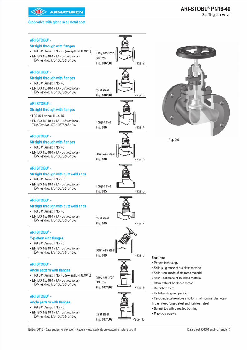
ARI-STOBU® PN16-40Stuffing box valve
Stop valve with gland seal metal seat
Features:
Proven technology
Solid plug made of stainless material
Solid stem made of stainless material
Solid seat made of stainless material
Stem with roll hardened thread
Burnished stem
High-tensile gland packingFavourable zeta-values also for small nominal diameters
In cast steel, forged steel and stainless steel:
Bonnet top with threaded bushing
Flap-type screws
•
•
•
•
•
•
••
•
•
Fig. 006
8/16/2019 Valve Ari Armaturen
http://slidepdf.com/reader/full/valve-ari-armaturen 2/162 Edition 06/13 - Data subject to alteration - Regularly updated data on www.ari-armaturen.com!
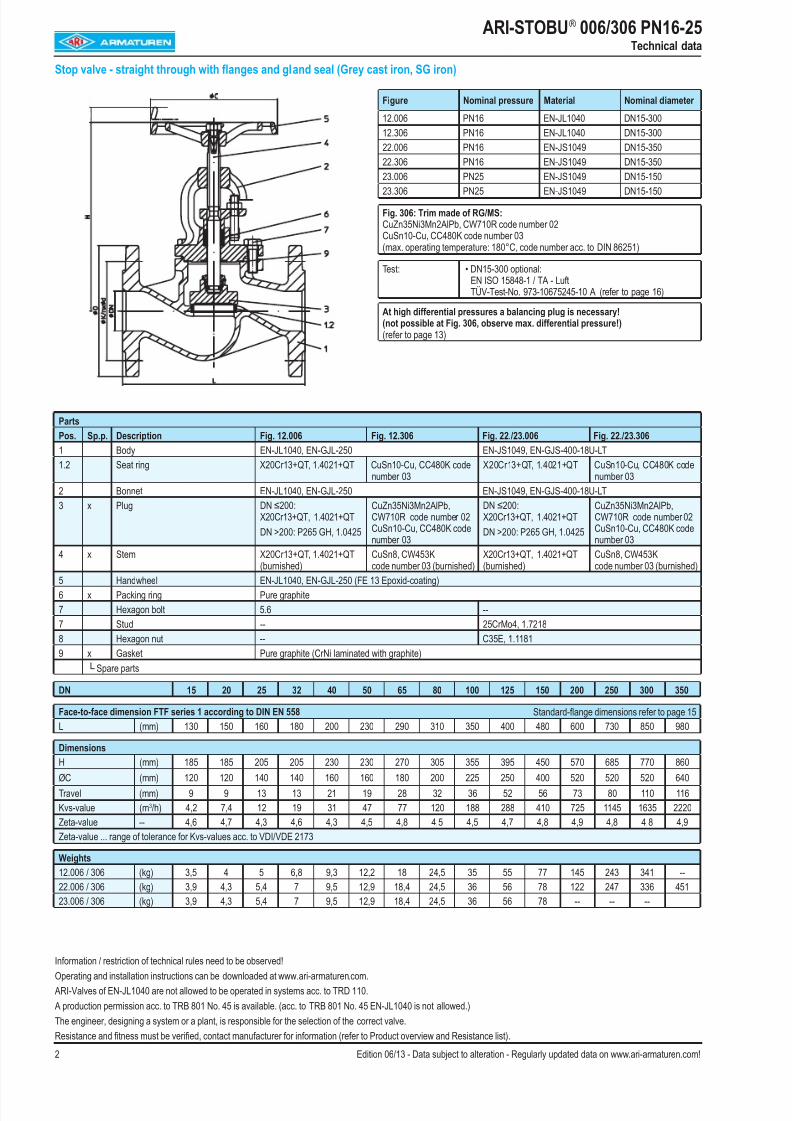
ARI-STOBU® 006/306 PN16-25Technical data
Stop valve - straight through with flanges and gland seal (Grey cast iron, SG iron)
Parts
Pos. Sp.p. Description Fig. 12.006 Fig. 12.306 Fig. 22./23.006 Fig. 22./23.306
1 Body EN-JL1040, EN-GJL-250 EN-JS1049, EN-GJS-400-18U-LT
1.2 Seat ring X20Cr13+QT, 1.4021+QT CuSn10-Cu, CC480K codenumber 03
X20Cr13+QT, 1.4021+QT CuSn10-Cu, CC480K codenumber 03
2 Bonnet EN-JL1040, EN-GJL-250 EN-JS1049, EN-GJS-400-18U-LT
3 x Plug DN ≤200:X20Cr13+QT, 1.4021+QT
DN >200: P265 GH, 1.0425
CuZn35Ni3Mn2AlPb,CW710R code number 02CuSn10-Cu, CC480K codenumber 03
DN ≤200:X20Cr13+QT, 1.4021+QT
DN >200: P265 GH, 1.0425
CuZn35Ni3Mn2AlPb,CW710R code number 02
CuSn10-Cu, CC480K codenumber 03
4 x Stem X20Cr13+QT, 1.4021+QT
(burnished)
CuSn8, CW453K
code number 03 (burnished)
X20Cr13+QT, 1.4021+QT
(burnished)
CuSn8, CW453K
code number 03 (burnished)5 Handwheel EN-JL1040, EN-GJL-250 (FE 13 Epoxid-coating)
6 x Packing ring Pure graphite
7 Hexagon bolt 5.6 --
7 Stud -- 25CrMo4, 1.7218
8 Hexagon nut -- C35E, 1.1181
9 x Gasket Pure graphite (CrNi laminated with graphite)
└ Spare parts
DN 15 20 25 32 40 50 65 80 100 125 150 200 250 300 350
Face-to-face dimension FTF series 1 according to DIN EN 558 Standard-flange dimensions refer to page 15
L (mm) 130 150 160 180 200 230 290 310 350 400 480 600 730 850 980
Dimensions
H (mm) 185 185 205 205 230 230 270 305 355 395 450 570 685 770 860
ØC (mm) 120 120 140 140 160 160 180 200 225 250 400 520 520 520 640
Travel (mm) 9 9 13 13 21 19 28 32 36 52 56 73 80 110 116
Kvs-value (m3/h) 4,2 7,4 12 19 31 47 77 120 188 288 410 725 1145 1635 2220
Zeta-value -- 4,6 4,7 4,3 4,6 4,3 4,5 4,8 4,5 4,5 4,7 4,8 4,9 4,8 4,8 4,9
Zeta-value ... range of tolerance for Kvs-values acc. to VDI/VDE 2173
Weights
12.006 / 306 (kg) 3,5 4 5 6,8 9,3 12,2 18 24,5 35 55 77 145 243 341 --
22.006 / 306 (kg) 3,9 4,3 5,4 7 9,5 12,9 18,4 24,5 36 56 78 122 247 336 451
23.006 / 306 (kg) 3,9 4,3 5,4 7 9,5 12,9 18,4 24,5 36 56 78 -- -- --
Figure Nominal pressure Material Nominal diameter
12.006 PN16 EN-JL1040 DN15-300
12.306 PN16 EN-JL1040 DN15-300
22.006 PN16 EN-JS1049 DN15-350
22.306 PN16 EN-JS1049 DN15-350
23.006 PN25 EN-JS1049 DN15-150
23.306 PN25 EN-JS1049 DN15-150
Fig. 306: Trim made of RG/MS: CuZn35Ni3Mn2AlPb, CW710R code number 02CuSn10-Cu, CC480K code number 03(max. operating temperature: 180°C, code number acc. to DIN 86251)
Test: • DN15-300 optional:EN ISO 15848-1 / TA - LuftTÜV-Test-No. 973-10675245-10 A (refer to page 16)
At high differential pressures a balancing plug is necessary!(not possible at Fig. 306, observe max. differential pressure!)(refer to page 13)
Information / restriction of technical rules need to be observed!
Operating and installation instructions can be downloaded at www.ari-armaturen.com.
ARI-Valves of EN-JL1040 are not allowed to be operated in systems acc. to TRD 110.
A production permission acc. to TRB 801 No. 45 is available. (acc. to TRB 801 No. 45 EN-JL1040 is not allowed.)
The engineer, designing a system or a plant, is responsible for the selection of the correct valve.
Resistance and fitness must be verified, contact manufacturer for information (refer to Product overview and Resistance list).
8/16/2019 Valve Ari Armaturen
http://slidepdf.com/reader/full/valve-ari-armaturen 3/163Edition 06/13 - Data subject to alteration - Regularly updated data on www.ari-armaturen.com!
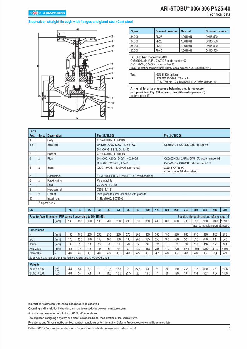
ARI-STOBU® 006/ 306 PN25-40Technical data
Stop valve - straight through with flanges and gland seal (Cast steel)
Parts
Pos. Sp.p. Description Fig. 34./35.006 Fig. 34./35.306
1 Body GP240GH+N, 1.0619+N
1.2 Seat ring DN ≤50: X20Cr13+QT, 1.4021+QT
DN >50: G19 9 Nb Si, 1.4551
CuSn10-Cu, CC480K code number 03
2 Bonnet GP240GH+N, 1.0619+N
3 x Plug DN ≤200: X20Cr13+QT, 1.4021+QT
DN >200: P265 GH, 1.0425
CuZn35Ni3Mn2AlPb, CW710R code number 02
CuSn10-Cu, CC480K code number 03 2)
4 x Stem X20Cr13+QT, 1.4021+QT (burnished) CuSn8, CW453Kcode number 03 (burnished)
5 Handwheel EN-JL1040, EN-GJL-250 (FE 13 Epoxid-coating)6 x Packing ring Pure graphite
7 Stud 25CrMo4, 1.7218
8 Hexagon nut C35E, 1.1181
9 x Gasket Pure graphite (CrNi laminated with graphite)
10 Insert nuts 11SMn30+C, 1.0715+C
└ Spare parts
DN 15 20 25 32 40 50 65 80 100 125 150 200 250 300 350 400 500
Face-to-face dimension FTF series 1 according to DIN EN 558 Standard-flange dimensions refer to page 15
L (mm) 130 150 160 180 200 230 290 310 350 400 480 600 730 850 980 1100 1350 *
* acc. to manufacturers standard
Dimensions
H (mm) 185 185 205 205 230 230 270 305 355 395 450 570 685 770 860 865 995ØC (mm) 120 120 140 140 160 160 180 200 225 250 400 520 520 520 640 640 640
Travel (mm) 9 9 13 13 21 19 28 32 36 52 56 73 80 110 116 126 181
Kvs-value (m3/h) 4,2 7,4 12 19 31 47 77 120 188 288 410 725 1145 1635 2220 3180 4530
Zeta-value -- 4,6 4,7 4,3 4,6 4,3 4,5 4,8 4,5 4,5 4,7 4,8 4,9 4,8 4,8 4,9 3,4 4,9
Zeta-value ... range of tolerance for Kvs-values acc. to VDI/VDE 2173
Weights
34.006 / 306 (kg) 4,4 5,4 6,3 7 10,5 13,8 21 27,5 40 61 84 160 265 377 510 780 1095
35.006 / 306 (kg) 4,8 5,4 7,1 8 11,5 13,5 23,5 28 39,5 61 84 170 283 414 557 857 1150
Figure Nominal pressure Material Nominal diameter
34.006 PN25 1.0619+N DN15-500
34.306 PN25 1.0619+N DN15-500
35.006 PN40 1.0619+N DN15-500
35.306 PN40 1.0619+N DN15-500
Fig. 306: Trim made of RG/MS CuZn35Ni3Mn2AlPb, CW710R code number 02CuSn10-Cu, CC480K code number 03(max. operating temperature: 180°C, code number acc. to DIN 86251)
Test: • DN15-300 optional :EN ISO 15848-1 / TA - LuftTÜV-Test-No. 973-10675245-10 A (refer to page 16)
At high differential pressures a balancing plug is necessary!(not possible at Fig. 306, observe max. differential pressure!)(refer to page 13)
Information / restriction of technical rules need to be observed!
Operating and installation instructions can be downloaded at www.ari-armaturen.com.
A production permission acc. to TRB 801 No. 45 is available.
The engineer, designing a system or a plant, is responsible for the selection of the correct valve.
Resistance and fitness must be verified, contact manufacturer for information (refer to Product overview and Resistance list).
8/16/2019 Valve Ari Armaturen
http://slidepdf.com/reader/full/valve-ari-armaturen 4/164 Edition 06/13 - Data subject to alteration - Regularly updated data on www.ari-armaturen.com!
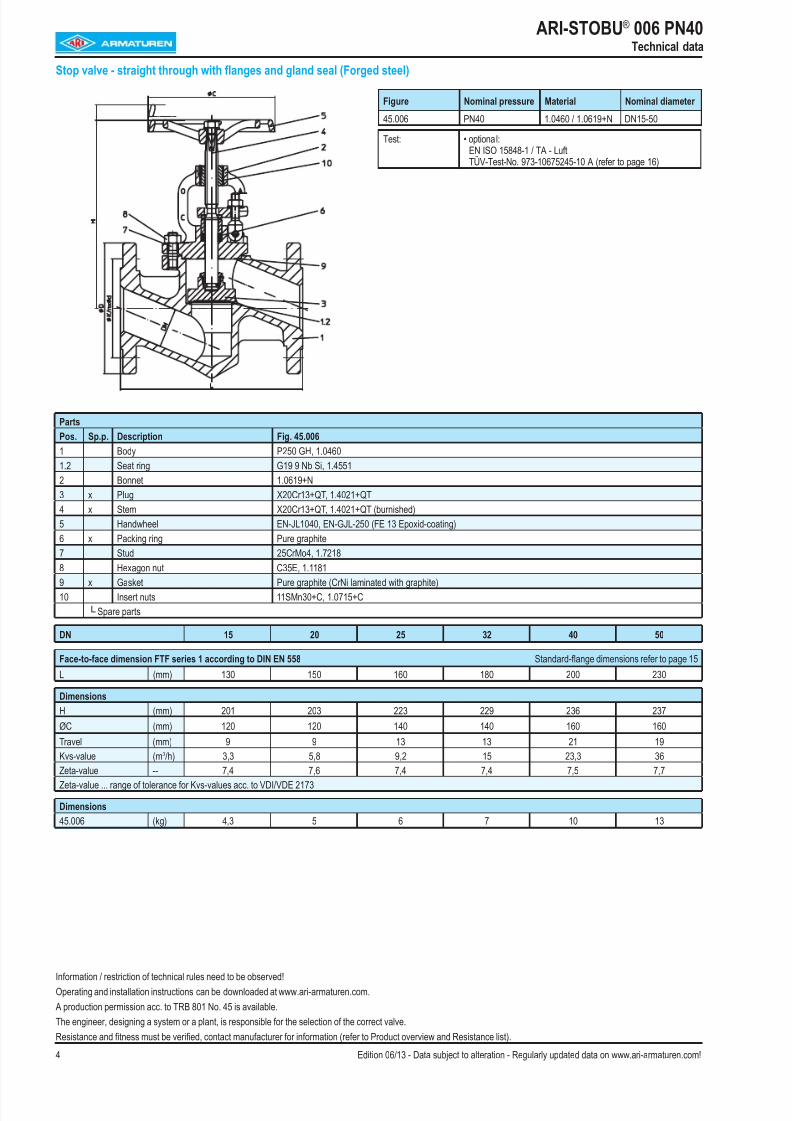
ARI-STOBU® 006 PN40Technical data
Stop valve - straight through with flanges and gland seal (Forged steel)
Parts
Pos. Sp.p. Description Fig. 45.006
1 Body P250 GH, 1.0460
1.2 Seat ring G19 9 Nb Si, 1.4551
2 Bonnet 1.0619+N
3 x Plug X20Cr13+QT, 1.4021+QT
4 x Stem X20Cr13+QT, 1.4021+QT (burnished)
5 Handwheel EN-JL1040, EN-GJL-250 (FE 13 Epoxid-coating)
6 x Packing ring Pure graphite
7 Stud 25CrMo4, 1.7218
8 Hexagon nut C35E, 1.11819 x Gasket Pure graphite (CrNi laminated with graphite)
10 Insert nuts 11SMn30+C, 1.0715+C
└ Spare parts
DN 15 20 25 32 40 50
Face-to-face dimension FTF series 1 according to DIN EN 558 Standard-flange dimensions refer to page 15
L (mm) 130 150 160 180 200 230
Dimensions
H (mm) 201 203 223 229 236 237
ØC (mm) 120 120 140 140 160 160
Travel (mm) 9 9 13 13 21 19
Kvs-value (m3/h) 3,3 5,8 9,2 15 23,3 36Zeta-value -- 7,4 7,6 7,4 7,4 7,5 7,7
Zeta-value ... range of tolerance for Kvs-values acc. to VDI/VDE 2173
Dimensions
45.006 (kg) 4,3 5 6 7 10 13
Figure Nominal pressure Material Nominal diameter
45.006 PN40 1.0460 / 1.0619+N DN15-50
Test: • optional:EN ISO 15848-1 / TA - LuftTÜV-Test-No. 973-10675245-10 A (refer to page 16)
Information / restriction of technical rules need to be observed!
Operating and installation instructions can be downloaded at www.ari-armaturen.com.
A production permission acc. to TRB 801 No. 45 is available.
The engineer, designing a system or a plant, is responsible for the selection of the correct valve.
Resistance and fitness must be verified, contact manufacturer for information (refer to Product overview and Resistance list).
8/16/2019 Valve Ari Armaturen
http://slidepdf.com/reader/full/valve-ari-armaturen 5/165Edition 06/13 - Data subject to alteration - Regularly updated data on www.ari-armaturen.com!
ARI-STOBU® 006 PN16-40Technical data
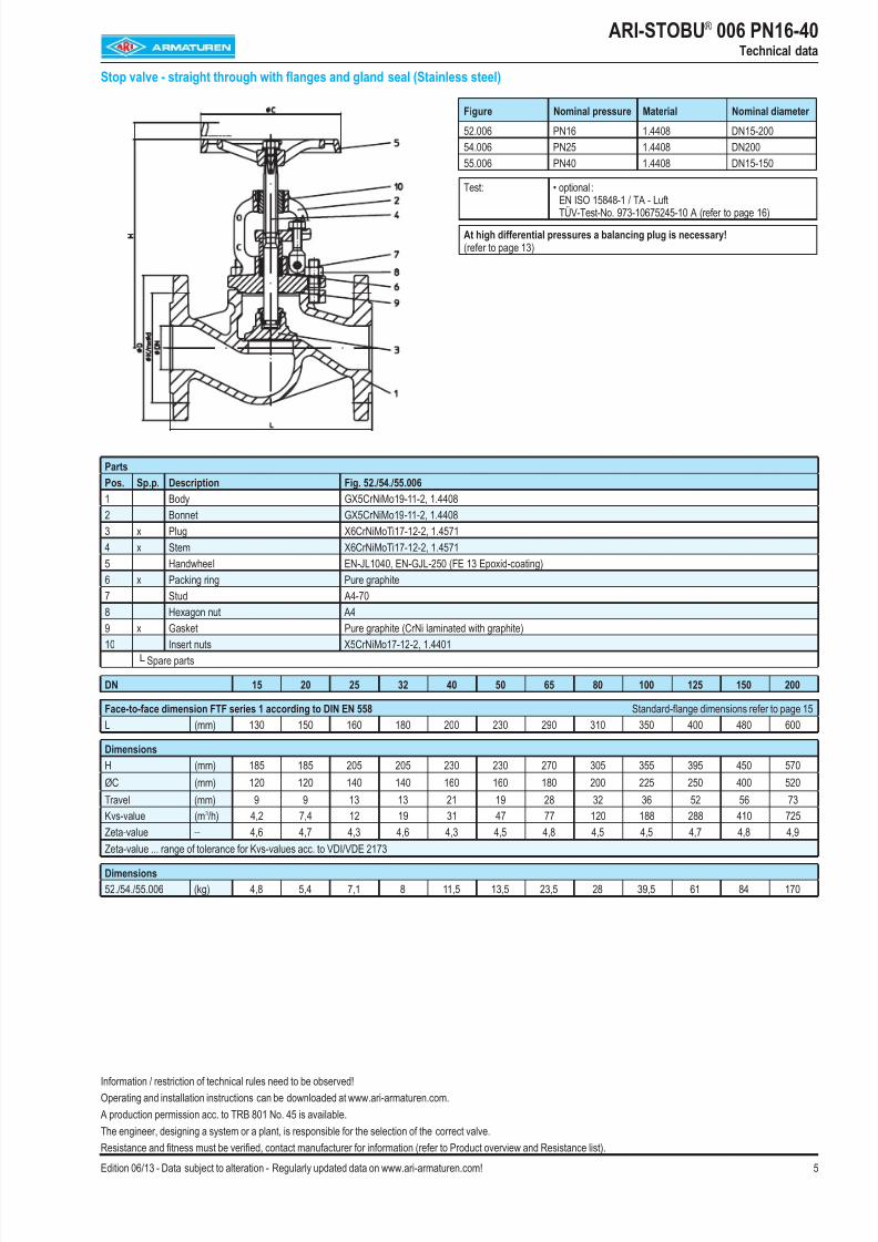
Stop valve - straight through with flanges and gland seal (Stainless steel)
Parts
Pos. Sp.p. Description Fig. 52./54./55.006
1 Body GX5CrNiMo19-11-2, 1.4408
2 Bonnet GX5CrNiMo19-11-2, 1.4408
3 x Plug X6CrNiMoTi17-12-2, 1.4571
4 x Stem X6CrNiMoTi17-12-2, 1.4571
5 Handwheel EN-JL1040, EN-GJL-250 (FE 13 Epoxid-coating)
6 x Packing ring Pure graphite
7 Stud A4-70
8 Hexagon nut A4
9 x Gasket Pure graphite (CrNi laminated with graphite)10 Insert nuts X5CrNiMo17-12-2, 1.4401
└ Spare parts
DN 15 20 25 32 40 50 65 80 100 125 150 200
Face-to-face dimension FTF series 1 according to DIN EN 558 Standard-flange dimensions refer to page 15
L (mm) 130 150 160 180 200 230 290 310 350 400 480 600
Dimensions
H (mm) 185 185 205 205 230 230 270 305 355 395 450 570
ØC (mm) 120 120 140 140 160 160 180 200 225 250 400 520
Travel (mm) 9 9 13 13 21 19 28 32 36 52 56 73
Kvs-value (m3/h) 4,2 7,4 12 19 31 47 77 120 188 288 410 725
Zeta-value -- 4,6 4,7 4,3 4,6 4,3 4,5 4,8 4,5 4,5 4,7 4,8 4,9Zeta-value ... range of tolerance for Kvs-values acc. to VDI/VDE 2173
Dimensions
52./54./55.006 (kg) 4,8 5,4 7,1 8 11,5 13,5 23,5 28 39,5 61 84 170
Figure Nominal pressure Material Nominal diameter
52.006 PN16 1.4408 DN15-200
54.006 PN25 1.4408 DN200
55.006 PN40 1.4408 DN15-150
Test: • optional :EN ISO 15848-1 / TA - LuftTÜV-Test-No. 973-10675245-10 A (refer to page 16)
At high differential pressures a balancing plug is necessary!(refer to page 13)
Information / restriction of technical rules need to be observed!
Operating and installation instructions can be downloaded at www.ari-armaturen.com.
A production permission acc. to TRB 801 No. 45 is available.
The engineer, designing a system or a plant, is responsible for the selection of the correct valve.
Resistance and fitness must be verified, contact manufacturer for information (refer to Product overview and Resistance list).
8/16/2019 Valve Ari Armaturen
http://slidepdf.com/reader/full/valve-ari-armaturen 6/166 Edition 06/13 - Data subject to alteration - Regularly updated data on www.ari-armaturen.com!
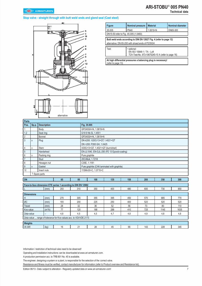
ARI-STOBU® 005 PN40Technical data
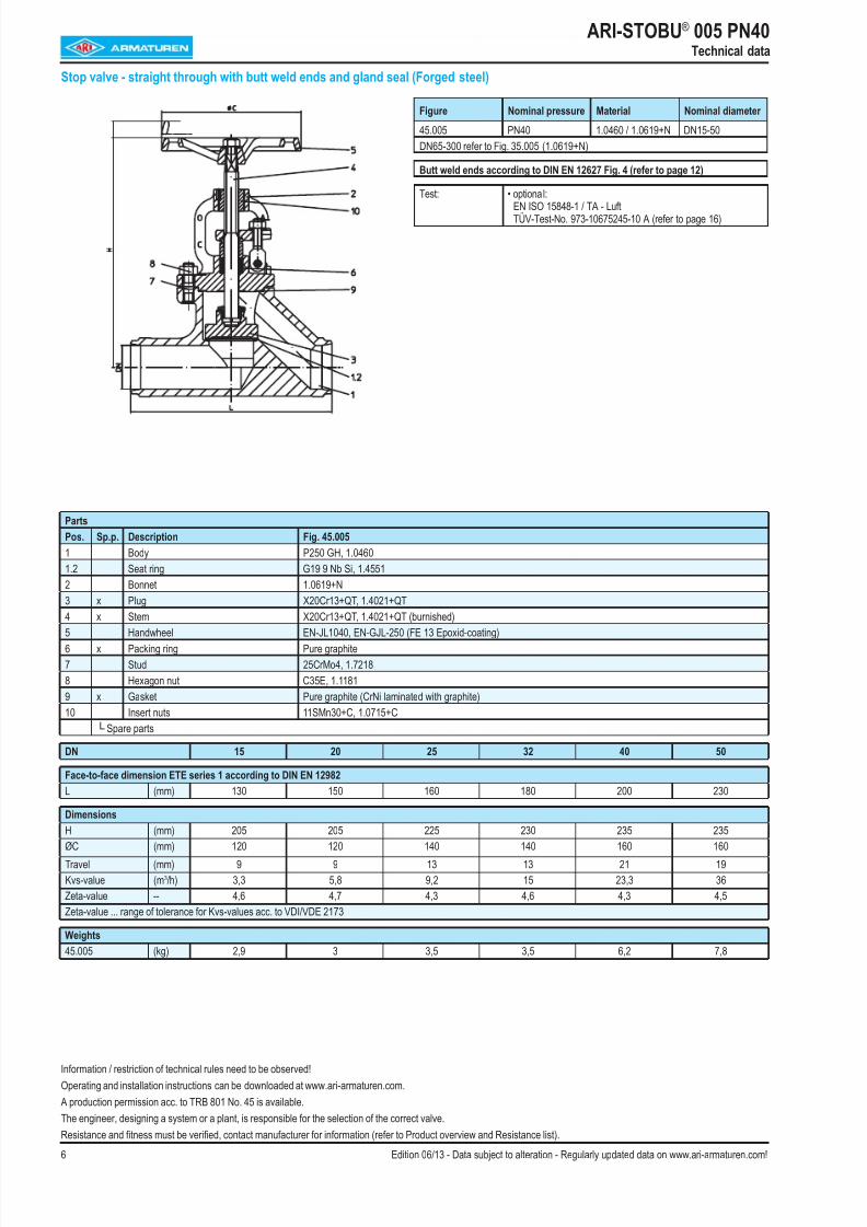
Stop valve - straight through with butt weld ends and gland seal (Forged steel)
Parts
Pos. Sp.p. Description Fig. 45.005
1 Body P250 GH, 1.0460
1.2 Seat ring G19 9 Nb Si, 1.4551
2 Bonnet 1.0619+N
3 x Plug X20Cr13+QT, 1.4021+QT
4 x Stem X20Cr13+QT, 1.4021+QT (burnished)5 Handwheel EN-JL1040, EN-GJL-250 (FE 13 Epoxid-coating)
6 x Packing ring Pure graphite
7 Stud 25CrMo4, 1.7218
8 Hexagon nut C35E, 1.1181
9 x Gasket Pure graphite (CrNi laminated with graphite)
10 Insert nuts 11SMn30+C, 1.0715+C
└ Spare parts
DN 15 20 25 32 40 50
Face-to-face dimension ETE series 1 according to DIN EN 12982
L (mm) 130 150 160 180 200 230
Dimensions
H (mm) 205 205 225 230 235 235ØC (mm) 120 120 140 140 160 160
Travel (mm) 9 9 13 13 21 19
Kvs-value (m3/h) 3,3 5,8 9,2 15 23,3 36
Zeta-value -- 4,6 4,7 4,3 4,6 4,3 4,5
Zeta-value ... range of tolerance for Kvs-values acc. to VDI/VDE 2173
Weights
45.005 (kg) 2,9 3 3,5 3,5 6,2 7,8
Figure Nominal pressure Material Nominal diameter
45.005 PN40 1.0460 / 1.0619+N DN15-50
DN65-300 refer to Fig. 35.005 (1.0619+N)
Butt weld ends according to DIN EN 12627 Fig. 4 (refer to page 12)
Test: • optional:
EN ISO 15848-1 / TA - LuftTÜV-Test-No. 973-10675245-10 A (refer to page 16)
Information / restriction of technical rules need to be observed!
Operating and installation instructions can be downloaded at www.ari-armaturen.com.
A production permission acc. to TRB 801 No. 45 is available.
The engineer, designing a system or a plant, is responsible for the selection of the correct valve.
Resistance and fitness must be verified, contact manufacturer for information (refer to Product overview and Resistance list).
8/16/2019 Valve Ari Armaturen
http://slidepdf.com/reader/full/valve-ari-armaturen 7/16
8/16/2019 Valve Ari Armaturen
http://slidepdf.com/reader/full/valve-ari-armaturen 8/168 Edition 06/13 - Data subject to alteration - Regularly updated data on www.ari-armaturen.com!
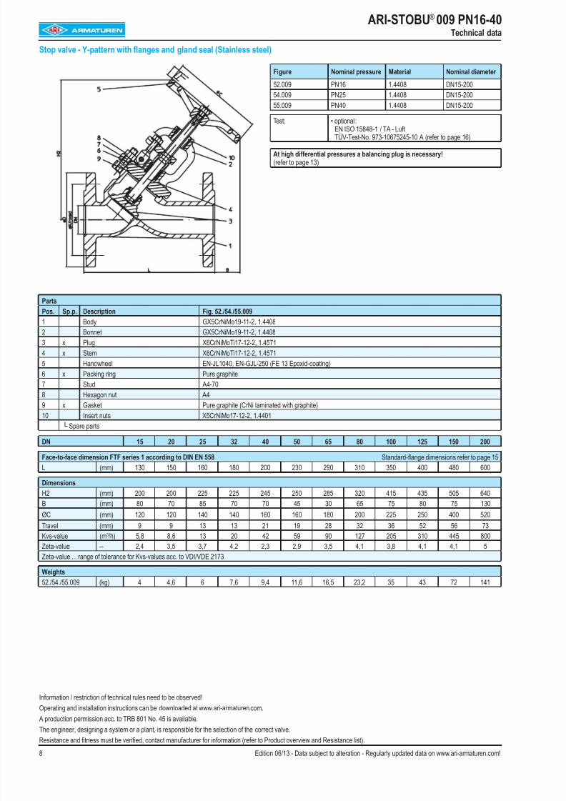
ARI-STOBU® 009 PN16-40Technical data
Stop valve - Y-pattern with flanges and gland seal (Stainless steel)
Parts
Pos. Sp.p. Description Fig. 52./54./55.009
1 Body GX5CrNiMo19-11-2, 1.4408
2 Bonnet GX5CrNiMo19-11-2, 1.4408
3 x Plug X6CrNiMoTi17-12-2, 1.4571
4 x Stem X6CrNiMoTi17-12-2, 1.4571
5 Handwheel EN-JL1040, EN-GJL-250 (FE 13 Epoxid-coating)
6 x Packing ring Pure graphite
7 Stud A4-70
8 Hexagon nut A4
9 x Gasket Pure graphite (CrNi laminated with graphite)10 Insert nuts X5CrNiMo17-12-2, 1.4401
└ Spare parts
DN 15 20 25 32 40 50 65 80 100 125 150 200
Face-to-face dimension FTF series 1 according to DIN EN 558 Standard-flange dimensions refer to page 15
L (mm) 130 150 160 180 200 230 290 310 350 400 480 600
Dimensions
H2 (mm) 200 200 225 225 245 250 285 320 415 435 505 640
B (mm) 80 70 85 70 70 45 30 65 75 80 75 130
ØC (mm) 120 120 140 140 160 160 180 200 225 250 400 520
Travel (mm) 9 9 13 13 21 19 28 32 36 52 56 73
Kvs-value (m3
/h) 5,8 8,6 13 20 42 59 90 127 205 310 445 800Zeta-value -- 2,4 3,5 3,7 4,2 2,3 2,9 3,5 4,1 3,8 4,1 4,1 5
Zeta-value ... range of tolerance for Kvs-values acc. to VDI/VDE 2173
Weights
52./54./55.009 (kg) 4 4,6 6 7,6 9,4 11,6 16,5 23,2 35 43 72 141
Figure Nominal pressure Material Nominal diameter
52.009 PN16 1.4408 DN15-200
54.009 PN25 1.4408 DN15-200
55.009 PN40 1.4408 DN15-200
Test: • optional :EN ISO 15848-1 / TA - LuftTÜV-Test-No. 973-10675245-10 A (refer to page 16)
At high differential pressures a balancing plug is necessary!(refer to page 13)
Information / restriction of technical rules need to be observed!
Operating and installation instructions can be downloaded at www.ari-armaturen.com.
A production permission acc. to TRB 801 No. 45 is available.
The engineer, designing a system or a plant, is responsible for the selection of the correct valve.
Resistance and fitness must be verified, contact manufacturer for information (refer to Product overview and Resistance list).
8/16/2019 Valve Ari Armaturen
http://slidepdf.com/reader/full/valve-ari-armaturen 9/169Edition 06/13 - Data subject to alteration - Regularly updated data on www.ari-armaturen.com!
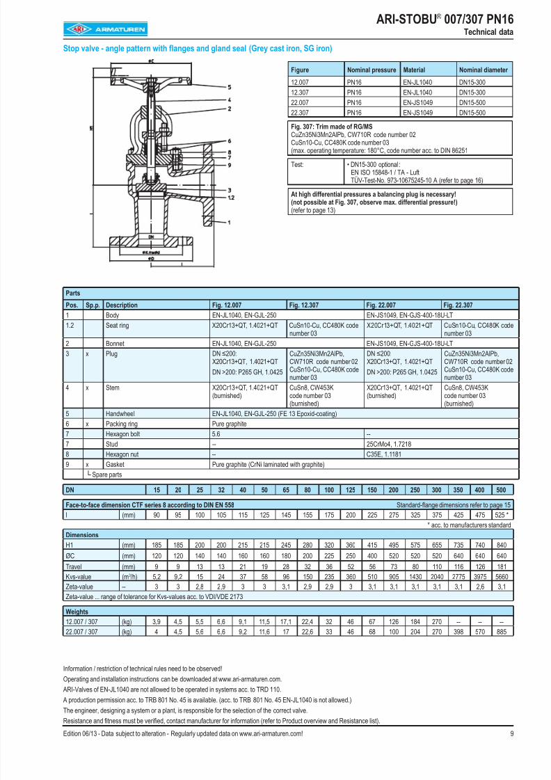
ARI-STOBU® 007/307 PN16Technical data
Stop valve - angle pattern with flanges and gland seal (Grey cast iron, SG iron)
Parts
Pos. Sp.p. Description Fig. 12.007 Fig. 12.307 Fig. 22.007 Fig. 22.307
1 Body EN-JL1040, EN-GJL-250 EN-JS1049, EN-GJS-400-18U-LT
1.2 Seat ring X20Cr13+QT, 1.4021+QT CuSn10-Cu, CC480K codenumber 03
X20Cr13+QT, 1.4021+QT CuSn10-Cu, CC480K codenumber 03
2 Bonnet EN-JL1040, EN-GJL-250 EN-JS1049, EN-GJS-400-18U-LT
3 x Plug DN ≤200:X20Cr13+QT, 1.4021+QT
DN >200: P265 GH, 1.0425
CuZn35Ni3Mn2AlPb,CW710R code number 02CuSn10-Cu, CC480K codenumber 03
DN ≤200:X20Cr13+QT, 1.4021+QT
DN >200: P265 GH, 1.0425
CuZn35Ni3Mn2AlPb,CW710R code number 02CuSn10-Cu, CC480K codenumber 03
4 x Stem X20Cr13+QT, 1.4021+QT
(burnished)
CuSn8, CW453K
code number 03(burnished)
X20Cr13+QT, 1.4021+QT
(burnished)
CuSn8, CW453K
code number 03(burnished)
5 Handwheel EN-JL1040, EN-GJL-250 (FE 13 Epoxid-coating)
6 x Packing ring Pure graphite
7 Hexagon bolt 5.6 --
7 Stud -- 25CrMo4, 1.7218
8 Hexagon nut -- C35E, 1.1181
9 x Gasket Pure graphite (CrNi laminated with graphite)
└ Spare parts
DN 15 20 25 32 40 50 65 80 100 125 150 200 250 300 350 400 500
Face-to-face dimension CTF series 8 according to DIN EN 558 Standard-flange dimensions refer to page 15
l (mm) 90 95 100 105 115 125 145 155 175 200 225 275 325 375 425 475 525 *
* acc. to manufacturers standardDimensions
H1 (mm) 185 185 200 200 215 215 245 280 320 360 415 495 575 655 735 740 840
ØC (mm) 120 120 140 140 160 160 180 200 225 250 400 520 520 520 640 640 640
Travel (mm) 9 9 13 13 21 19 28 32 36 52 56 73 80 110 116 126 181
Kvs-value (m3/h) 5,2 9,2 15 24 37 58 96 150 235 360 510 905 1430 2040 2775 3975 5660
Zeta-value -- 3 3 2,8 2,9 3 3 3,1 2,9 2,9 3 3,1 3,1 3,1 3,1 3,1 2,6 3,1
Zeta-value ... range of tolerance for Kvs-values acc. to VDI/VDE 2173
Weights
12.007 / 307 (kg) 3,9 4,5 5,5 6,6 9,1 11,5 17,1 22,4 32 46 67 126 184 270 -- -- --
22.007 / 307 (kg) 4 4,5 5,6 6,6 9,2 11,6 17 22,6 33 46 68 100 204 270 398 570 885
Figure Nominal pressure Material Nominal diameter
12.007 PN16 EN-JL1040 DN15-300
12.307 PN16 EN-JL1040 DN15-300
22.007 PN16 EN-JS1049 DN15-500
22.307 PN16 EN-JS1049 DN15-500
Fig. 307: Trim made of RG/MS CuZn35Ni3Mn2AlPb, CW710R code number 02CuSn10-Cu, CC480K code number 03(max. operating temperature: 180°C, code number acc. to DIN 86251
Test: • DN15-300 optional :EN ISO 15848-1 / TA - LuftTÜV-Test-No. 973-10675245-10 A (refer to page 16)
At high differential pressures a balancing plug is necessary!(not possible at Fig. 307, observe max. differential pressure!)(refer to page 13)
Information / restriction of technical rules need to be observed!
Operating and installation instructions can be downloaded at www.ari-armaturen.com.
ARI-Valves of EN-JL1040 are not allowed to be operated in systems acc. to TRD 110.
A production permission acc. to TRB 801 No. 45 is available. (acc. to TRB 801 No. 45 EN-JL1040 is not allowed.)
The engineer, designing a system or a plant, is responsible for the selection of the correct valve.
Resistance and fitness must be verified, contact manufacturer for information (refer to Product overview and Resistance list).
8/16/2019 Valve Ari Armaturen
http://slidepdf.com/reader/full/valve-ari-armaturen 10/1610 Edition 06/13 - Data subject to alteration - Regularly updated data on www.ari-armaturen.com!
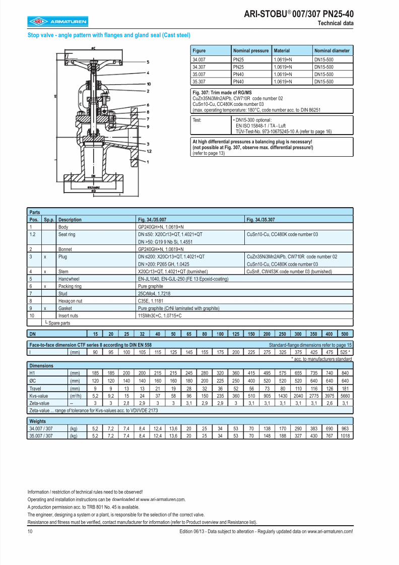
ARI-STOBU® 007/307 PN25-40Technical data
Stop valve - angle pattern with flanges and gland seal (Cast steel)
Parts
Pos. Sp.p. Description Fig. 34./35.007 Fig. 34./35.307
1 Body GP240GH+N, 1.0619+N
1.2 Seat ring DN ≤50: X20Cr13+QT, 1.4021+QT
DN >50: G19 9 Nb Si, 1.4551
CuSn10-Cu, CC480K code number 03
2 Bonnet GP240GH+N, 1.0619+N
3 x Plug DN ≤200: X20Cr13+QT, 1.4021+QT
DN >200: P265 GH, 1.0425
CuZn35Ni3Mn2AlPb, CW710R code number 02
CuSn10-Cu, CC480K code number 03
4 x Stem X20Cr13+QT, 1.4021+QT (burnished) CuSn8, CW453K code number 03 (burnished)
5 Handwheel EN-JL1040, EN-GJL-250 (FE 13 Epoxid-coating)
6 x Packing ring Pure graphite7 Stud 25CrMo4, 1.7218
8 Hexagon nut C35E, 1.1181
9 x Gasket Pure graphite (CrNi laminated with graphite)
10 Insert nuts 11SMn30+C, 1.0715+C
└ Spare parts
DN 15 20 25 32 40 50 65 80 100 125 150 200 250 300 350 400 500
Face-to-face dimension CTF series 8 according to DIN EN 558 Standard-flange dimensions refer to page 15
l (mm) 90 95 100 105 115 125 145 155 175 200 225 275 325 375 425 475 525 * * acc. to manufacturers standardDimensions
H1 (mm) 185 185 200 200 215 215 245 280 320 360 415 495 575 655 735 740 840
ØC (mm) 120 120 140 140 160 160 180 200 225 250 400 520 520 520 640 640 640Travel (mm) 9 9 13 13 21 19 28 32 36 52 56 73 80 110 116 126 181
Kvs-value (m3/h) 5,2 9,2 15 24 37 58 96 150 235 360 510 905 1430 2040 2775 3975 5660
Zeta-value -- 3 3 2,8 2,9 3 3 3,1 2,9 2,9 3 3,1 3,1 3,1 3,1 3,1 2,6 3,1
Zeta-value ... range of tolerance for Kvs-values acc. to VDI/VDE 2173
Weights
34.007 / 307 (kg) 5,2 7,2 7,4 8,4 12,4 13,6 20 25 34 53 70 138 170 290 383 690 963
35.007 / 307 (kg) 5,2 7,2 7,4 8,4 12,4 13,6 20 25 34 53 70 148 188 327 430 767 1018
Figure Nominal pressure Material Nominal diameter
34.007 PN25 1.0619+N DN15-500
34.307 PN25 1.0619+N DN15-500
35.007 PN40 1.0619+N DN15-500
35.307 PN40 1.0619+N DN15-500
Fig. 307: Trim made of RG/MSCuZn35Ni3Mn2AlPb, CW710R code number 02CuSn10-Cu, CC480K code number 03(max. operating temperature: 180°C, code number acc. to DIN 86251
Test: • DN15-300 optional :EN ISO 15848-1 / TA - LuftTÜV-Test-No. 973-10675245-10 A (refer to page 16)
At high differential pressures a balancing plug is necessary!(not possible at Fig. 307, observe max. differential pressure!)(refer to page 13)
Information / restriction of technical rules need to be observed!
Operating and installation instructions can be downloaded at www.ari-armaturen.com.
A production permission acc. to TRB 801 No. 45 is available.
The engineer, designing a system or a plant, is responsible for the selection of the correct valve.
Resistance and fitness must be verified, contact manufacturer for information (refer to Product overview and Resistance list).
8/16/2019 Valve Ari Armaturen
http://slidepdf.com/reader/full/valve-ari-armaturen 11/1611Edition 06/13 - Data subject to alteration - Regularly updated data on www.ari-armaturen.com!
ARI-STOBU® PN16-40Notes

8/16/2019 Valve Ari Armaturen
http://slidepdf.com/reader/full/valve-ari-armaturen 12/1612 Edition 06/13 - Data subject to alteration - Regularly updated data on www.ari-armaturen.com!
L = Face-to-face dimension
Edge shaping acc. to DIN EN 25817
ARI-STOBU® 005 PN16-40
Valves with butt weld ends
DN 15 20 25 32 40 50 65 80 100 125 150 200 250 300 350 400
Butt weld ends acc. to DIN EN 12627
L (mm) 130 150 160 180 200 230 290 310 350 400 480 600 730 850 980 1100
ØA (mm) 22 28 35 44 50 62 77 91 117 144 172 223 278 329 362 413
ØB (mm) 17,3 22,3 28,5 37,2 43,1 53,9 68,9 80,9 104,3 130,7 157,1 204,9 257 307,9 338 384,4
Ødi (mm) 15 20 25 32 40 50 65 80 100 125 150 200 250 300 330 375
R (mm) 3 3 3 3 3 3 3 3 3 3 3 5 5 5 5 5
L1 (similar) (mm) 10 10 10 10 10 10 10 12 14 18 20 20 25 33 45 45
Ød3 (mm) 21,3 26,9 33,7 42,4 48,3 60,3 76,1 88,9 114,3 139,7 168,3 219,1 273,0 323,9 355,6 406,4
s1 (mm) 2 2,3 2,6 2,6 2,6 3,2 3,6 4 5 4,5 5,6 7,1 8 8 8,8 11
Face-to-face dimension ETE series 1 according to DIN EN 12982
Butt weld ends according to DIN EN 12627 Fig. 4
Weld joint according to DIN EN 29692 code number 1.3.3
The material used for ARI valves with butt weld ends are:GP240GH+N, 1.0619+N acc. to DIN EN 10213-2,P250GH, 1.0460 acc. to DIN EN 10222-2.
DN 15 20 25 32 40 50 65 80 100 125 150 200 250 300 350 400
Shoed ends made of P235GH (Pipe connection =̂ welding neck flanges)
Ød (mm) -- -- -- -- -- -- 76,1 88,9 114,3 139,7 168,3 219,1 -- -- -- --
Øs (mm) -- -- -- -- -- -- 2,9 3,2 3,6 4,0 4,5 6,3 -- -- -- --
The material used for ARI valves with shoed ends (DN 65-200) P235GH according to DIN EN 10216-2.
Based on our experience we recommend electric welding process for connecting valves or strainers with tubes or with each other.
Lime based electrodes with an appropriate composite material should be used as filler material for welding.
Gas welding should be avoided.
Because of the different material compositions and wall thickness of the steam traps and the pipe gas welding shall not be applied. Quenching cracks and coarse grainstructure may develop.
8/16/2019 Valve Ari Armaturen
http://slidepdf.com/reader/full/valve-ari-armaturen 13/1613Edition 06/13 - Data subject to alteration - Regularly updated data on www.ari-armaturen.com!
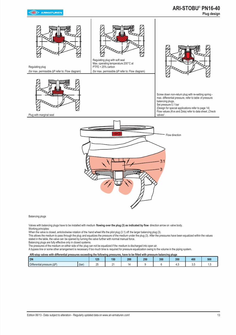
ARI-STOBU® PN16-40
Plug design
Regulating plug
(for max. permissible ΔP refer to: Flow diagram)
Regulating plug with soft sealMax. operating temperature 200°C atPTFE + 25% carbon
(for max. permissible ΔP refer to: Flow diagram)
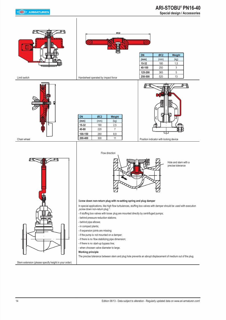
Screw down non-return plug with re-setting spring -max. differential pressure, refer to table of pressurebalancing plugs,Set pressure 0,1 bar(Design for special applications refer to page 14)
Flow values (Kvs and Zeta) refer to data sheet „Checkvalves“.Plug with marginal seat
Balancing plugs
Valves with balancing plugs have to be installed with medium flowing over the plug (3) as indicated by flow direction arrow on valve body.Working principles:When the valve is closed, anticlockwise rotation of the hand wheel lifts the pilot plug (3.1) off the larger balancing plug (3).This allows the medium to pass through the plug and equalizes the pressure of the medium under the plug (3). After the pressures have been equalized within the valuesstated in the table, the valve can be opened by turning the valve further with normal manual force.Balancing plugs are fully effective only in closed systems.The pressures of the medium on either side of the plug can not be equalized if the medium is discharged into open air.A bypass line or some other arrangement is necessary if too much time is required for pressure equalization owing to the volume in the piping system.
ARI-stop valves with differential pressures exceeding the following pressures, have to be fitted with pressure balancing plugs
DN 125 150 200 250 300 350 400 500
Differential pressure (ΔP) (bar) 25 21 14 9 6 4,5 3,5 1,5
Flow direction
8/16/2019 Valve Ari Armaturen
http://slidepdf.com/reader/full/valve-ari-armaturen 14/16
8/16/2019 Valve Ari Armaturen
http://slidepdf.com/reader/full/valve-ari-armaturen 15/1615Edition 06/13 - Data subject to alteration - Regularly updated data on www.ari-armaturen.com!
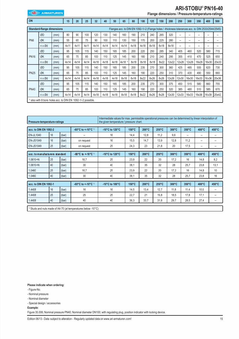
Pressure-temperature-ratingsIntermediate values for max. permissible operational pressures can be determined by linear interpolation ofthe given temperature / pressure chart.
acc. to DIN EN 1092-2 -60°C to <-10°C 1) -10°C to 120°C 150°C 200°C 250°C 300°C 350°C 400°C 450°C
EN-JL1040 16 (bar) -- 16 14,4 12,8 11,2 9,6 -- -- --
EN-JS1049 16 (bar) on request 16 15,5 14,7 13,9 12,8 11,2 -- --
EN-JS1049 25 (bar) on request 25 24,3 23 21,8 20 17,5 -- --
acc. to manufacturers standard -60°C to <-10°C 1) -10°C to 120°C 150°C 200°C 250°C 300°C 350°C 400°C 450°C
1.0619+N 25 (bar) 18,7 25 23,9 22 20 17,2 16 14,8 8,2
1.0619+N 40 (bar) 30 40 38,1 35 32 28 25,7 23,8 13,1
1.0460 25 (bar) 18,7 25 23,9 22 20 17,2 16 14,8 101.0460 40 (bar) 30 40 38,1 35 32 28 25,7 23,8 16
acc. to DIN EN 1092-1 -60°C to <-10°C 1) -10°C to 100°C 150°C 200°C 250°C 300°C 350°C 400°C 450°C
1.4408 16 (bar) 16 16 14,5 13,4 12,7 11,8 11,4 10,9 --
1.4408 25 (bar) 25 25 22,7 21 19,8 18,5 17,8 17,1 --
1.4408 40 (bar) 40 40 36,3 33,7 31,8 29,7 28,5 27,4 --
1) Studs and nuts made of A4-70 (at temperatures below -10°C)
Please indicate when ordering:- Figure-No.
- Nominal pressure
- Nominal diameter
- Special design / accessories
Example:
Figure 35.006; Nominal pressure PN40; Nominal diameter DN100; with regulating plug, position indicator with locking device.
ARI-STOBU® PN16-40 Flange dimensions / Pressure-temperature-ratings
DN 15 20 25 32 40 50 65 80 100 125 150 200 250 300 350 400 500
Standard-flange dimensions Flanges acc. to DIN EN 1092-1/-2 (Flange holes / -thickness tolerances acc. to DIN 2533/2544/2545)
PN6
ØD (mm) 80 90 100 120 130 140 160 190 210 240 265 320 -- -- -- -- --
ØK (mm) 55 65 75 90 100 110 130 150 170 200 225 280 -- -- -- -- --
n x Ød (mm) 4x11 4x11 4x11 4x14 4x14 4x14 4x14 4x18 4x18 8x18 8x18 8x18 -- -- -- -- --
PN16
ØD (mm) 95 105 115 140 150 165 185 200 220 250 285 340 405 460 520 580 715
ØK (mm) 65 75 85 100 110 125 145 160 180 210 240 295 355 410 470 525 650n x Ød (mm) 4x14 4x14 4x14 4x18 4x18 4x18 4x18 1) 8x18 8x18 8x18 8x22 12x22 12x26 12x26 16x26 16x30 20x33
PN25
ØD (mm) 95 105 115 140 150 165 185 200 235 270 300 360 425 485 555 620 730
ØK (mm) 65 75 85 100 110 125 145 160 190 220 250 310 370 430 490 550 660
n x Ød (mm) 4x14 4x14 4x14 4x18 4x18 4x18 8x18 8x18 8x22 8x26 8x26 12x26 12x30 16x30 16x33 16x36 20x36
PN40
ØD (mm) 95 105 115 140 150 165 185 200 235 270 300 375 450 515 580 660 755
ØK (mm) 65 75 85 100 110 125 145 160 190 220 250 320 385 480 510 585 670
n x Ød (mm) 4x14 4x14 4x14 4x18 4x18 4x18 8x18 8x18 8x22 8x26 8x26 12x30 12x33 16x33 16x36 16x39 20x42
1) also with 8 bore holes acc. to DIN EN 1092-1/-2 possible.
8/16/2019 Valve Ari Armaturen
http://slidepdf.com/reader/full/valve-ari-armaturen 16/16
ARI-STOBU® PN16-40
Test EN ISO 15848-1 / TA - Luft
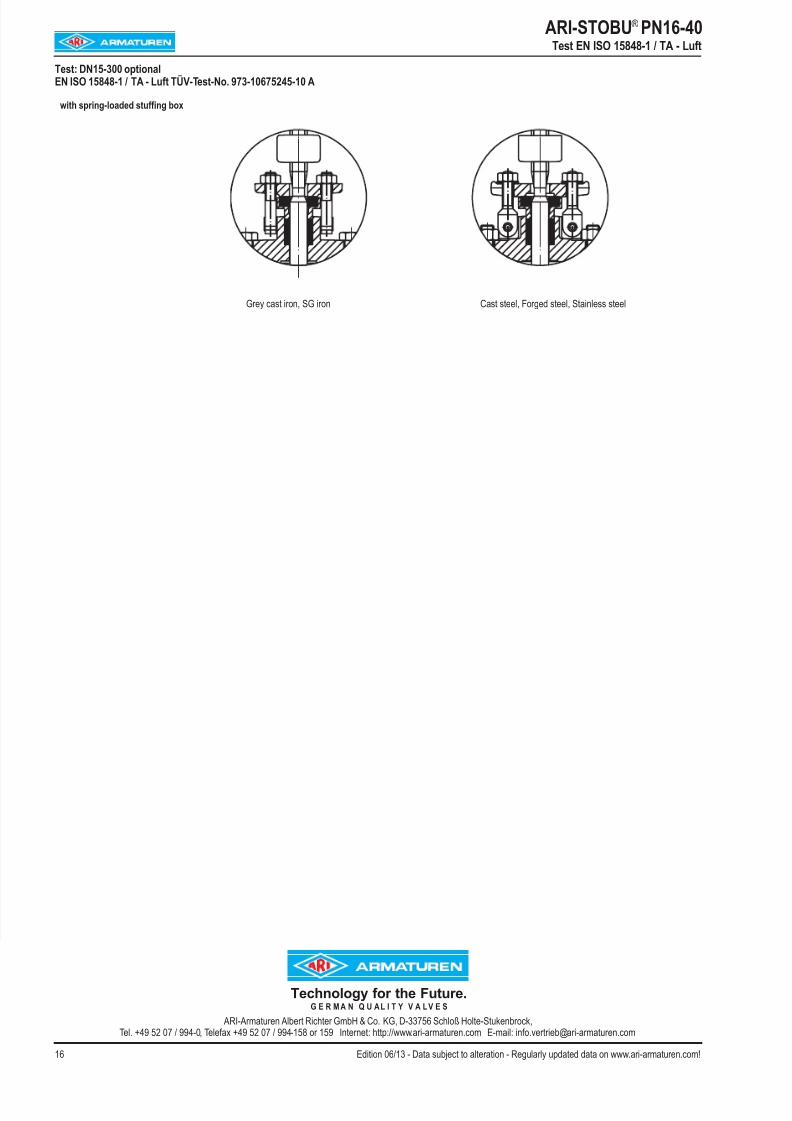
Test: DN15-300 optionalEN ISO 15848-1 / TA - Luft TÜV-Test-No. 973-10675245-10 A
with spring-loaded stuffing box
Grey cast iron, SG iron Cast steel, Forged steel, Stainless steel
Technology for the Future. G E R M A N Q U A L I T Y V A L V E S
ARI A t Alb t Ri ht G bH & C KG D 33756 S hl ß H lt St k b k