vacuum tubes transistor 1948 ics 1960s microprocessors 1970s
Post on 19-Dec-2015
225 views
TRANSCRIPT

• Vacuum tubes
• Transistor 1948
• ICs 1960s
• Microprocessors 1970s
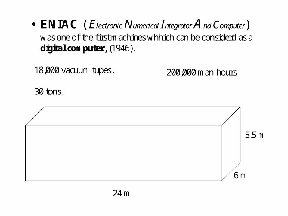
• ENIAC ( Electronic Numerical Integrator A nd Computer)was one of the first machines whhich can be considerd as adigital computer, (1946).
5.5 m
24 m
18,000 vacuum tupes.
30 tons.
6 m
200,000 man-hours

• The problem is not only in size, cost …
• The problem is that whenever you want to program it you need to re-wiring & setting many switches.
• Von Neumann or Stored Program concept was the solution.
• The Resulting Computer is software programmed not hardware programmed

What is the microprocessor• compact integrated circuit• very simple machine, endlessly follows the sequence:
• Fetch the next instruction in sequence from memory
• excute the instruction
• go to step 1.
• Complex timing unit

FIGURE 3-2 (a) The nonpipelined microprocessor follows a sequential fetch and execute cycle. (b) The 8086’s pipelined architecture allows the EU to execute instructions without the delays associated with instruction fetching.
John UffenbeckThe 80x86 Family: Design, Programming, and Interfacing, 3e
Copyright ©2002 by Pearson Education, Inc.Upper Saddle River, New Jersey 07458
All rights reserved.

Control Memory
ALURegisters
Early computersseparate functions by separate chips

Control Bus
I/ODevices
Memory
CPU(ALU +Reg +
control)
Data BusAddress Bus
Early microprocessors control, registers, arithmetic logic are integrated in one chip

Modern MicroprocessorsInternal memory (cashe) + advanced BIU unit and memory management
I/ODevices
Memory
Data Bus
Address Bus
Control Bus
Registers, ALU,Fetch,Exe Logic,Bus logic,Cache Memory

Why 8086• It has the basic architecture and standards for the
following processors.• It is used to build the first IBM PC. (its major advantage
which makes the PC possible is separating the execution unit and the BIU allowing instruction execution while fetching the following ones.)
• It is used in the LAB!
HoweverMany concepts will be explained in general with
8086 as Example.
Also, we will point to some of the advanced features of the more modern microprocessors

BussesData Bus
• The microprocessor is usually characterized by its size of its data bus:
4-bit microprocessor (4004) 8- bit microprocessors (8008)
16-bit microprocessor (8086) 32-bit microprocessor (386 &486)
64-bit microprocessor (Pentium & above)
• Note: you should differentiate between the size of external data bus size and the internal data bus size (registers).
8088 has 16 bit internal reg. But 8-bit external data bus.
386SX has 32 bit internal reg. But 16-bit external data bus.
However, from Pentium and above the registers size is 32 bit while the external data bus is 64 bit.
Note: Internal registers size did not change since the 386 (32 bits). (Why?)

Busses2- Address bus
• 20 address bus --- max memory size?
• 24 address bus --- max memory size?
• 32 address bus --- max memory size?
• 36 address bus --- max memory size?
• Memory divided into banks (486 example)

BussesControl bus
• Control bus signals like: M/IO , WR, RD
What is active low?

The 80286• First Intel microprocessor offering protected mode.• data bus remains:16 bit , address bus became 24 bit• In real mode, It is like 8086 with a faster clock. • in protected mode, It supports multiprogram
environment by assigning segments for each program.
• once switched to protected mode can not switch back to real mode.
• since DOS require programs to be running in real mode, it turns to be that 286 functions only as 8086

The 80386• 386 has become the foundation of the following
Intel processors.
• New features for the protected mode:– Its ability to switch between the modes.
– Having a new feature: the virtual 8086 mode
• Architecture changes:– Internal data bus increased to 32 bits– address bus increased to 32 bits (memory?)– Many new instruction were added

The 80386- Operating Modes
Real Mode• 386 starts by running the Real Mode working exactly as
8086 (20 address lines, same segmented memory)
• Also runs real mod applications (eg. DOS applications)• Limitations:
– Memory space is 1MB– One program at a time– All protection and memory management features of 386 are
disabled.
• Two new features – 32–bit registers can be accessed– Two new segments F and G

The 80386- Operating ModesProtected Mode
• Main improvements:– New memory addressing mechanism– Protection levels
• New memory addressing mechanism– Segmentation: not limited to 64K and segment registers are
indirectly used.– Paging: memory is divided to memory blocks of 4KB each.– Both can use virtual memory
• Protection levels– this mode has the ability to assign privilege level for each task.

The 80386- Operating Modes
Virtual 8086 mode (Protected Real Mode )
• In this mode, 386 hands each Real Mode program its own I MB memory allowing multiple 8086 programs to be rum simultaneously protected from each other.

The 80386 internal Model• BIU:
– manages all the bus signals – keeps the instruction queue (16 byte) full (advantage?)– 32 data lines require memory to be arranged in 4-banks
• This allows Dword (4 Bytes) to be accessed in one Bus Cycle ( provided they are aligned).
– Address pipelining (new feature)• The address of the next memory location is output during the current
cycle
– Dynamic bus sizing (new feature)• Switch between 16 and 32 data lines dynamically to accommodate 16-bit
external data interface. In this case, BIU only uses the low 16-bits of the data bus.
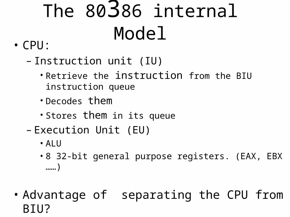
The 80386 internal Model• CPU:
– Instruction unit (IU)• Retrieve the instruction from the BIU instruction queue
• Decodes them• Stores them in its queue
– Execution Unit (EU)• ALU
• 8 32-bit general purpose registers. (EAX, EBX ……)
• Advantage of separating the CPU from BIU?

The 80386 internal Model• MMU:
– Segmentation Unit• In real mode, it generates 20 bit address • In protected mode, a segment register works as a pointer to a
8 byte descriptor table having the information about segment base address, size, and attributes.
– Descriptor registrars:– a copy of descriptor table for each active segment is stored in MMU
– Paging Unit: access the memory in 4KB pages• Only the most current pages are kept in memory• Other pages swapped out to the hard disk (virtual memory).• Locating a specific page is time consuming, so:• Address of the 32 most recently used pages are stored in the
page cash (TLB translation look aside buffer)
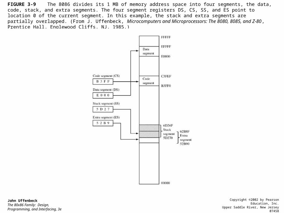
FIGURE 3-9 The 8086 divides its 1 MB of memory address space into four segments, the data, code, stack, and extra segments. The four segment registers DS, CS, SS, and ES point to location 0 of the current segment. In this example, the stack and extra segments are partially overlapped. (From J. Uffenbeck, Microcomputers and Microprocessors: The 8080, 8085, and Z-80, Prentice Hall, Englewood Cliffs, NJ, 1985.)
John UffenbeckThe 80x86 Family: Design, Programming, and Interfacing, 3e
Copyright ©2002 by Pearson Education, Inc.Upper Saddle River, New Jersey 07458
All rights reserved.

FIGURE 3-15 80386 Protected Mode addressing. Physical addresses are computed by adding the instruction offset to the segment base address stored in a descriptor table. The upper 13 bits of the segment register are used to point to a specific descriptor. The base address and limit of the descriptor tables are stored in the global and local descriptor table registers (GDTR and LDTR).
John UffenbeckThe 80x86 Family: Design, Programming, and Interfacing, 3e
Copyright ©2002 by Pearson Education, Inc.Upper Saddle River, New Jersey 07458
All rights reserved.

FIGURE 3-14 In Protected Mode each segment register points to the base of a descriptor table. Entries in these tables, called descriptors, are eight bytes long and specify the starting address of the segment, its size limit, and its attributes.
John UffenbeckThe 80x86 Family: Design, Programming, and Interfacing, 3e
Copyright ©2002 by Pearson Education, Inc.Upper Saddle River, New Jersey 07458
All rights reserved.

FIGURE 3-11 The processor model for the 80386 microprocessor consists of the bus interface unit (BIU), central processing unit (CPU), and the memory management unit (MMU).
John UffenbeckThe 80x86 Family: Design, Programming, and Interfacing, 3e
Copyright ©2002 by Pearson Education, Inc.Upper Saddle River, New Jersey 07458
All rights reserved.

FIGURE 3-12 Programming model for the 80386. The general-purpose registers (a) are used by applications programmers. The special-purpose registers (b) are intended to be used by the operating system software.
John UffenbeckThe 80x86 Family: Design, Programming, and Interfacing, 3e
Copyright ©2002 by Pearson Education, Inc.Upper Saddle River, New Jersey 07458
All rights reserved.

FIGURE 3-12 Continued
John UffenbeckThe 80x86 Family: Design, Programming, and Interfacing, 3e
Copyright ©2002 by Pearson Education, Inc.Upper Saddle River, New Jersey 07458
All rights reserved.

FIGURE 3-17 When paging is enabled, linear addresses are translated into physical addresses via the Page Directory and Page Translation tables.
John UffenbeckThe 80x86 Family: Design, Programming, and Interfacing, 3e
Copyright ©2002 by Pearson Education, Inc.Upper Saddle River, New Jersey 07458
All rights reserved.

The 80486• Keaps all features of 386: (Modes of operation, memory management,
protection levels, registers, bus sizes)• The two most significant improvements are:
– On board cache memory (8KB or 16KB)– Floating point unit
• Other improvements:– Five stage instruction pipeline– Six new instructions – Alignment check flag

The 80486Five stage instruction pipeline:
– Prefetch (PF) instructions are placed in one of two queues
– Decode stage 1 (D1) to determine the instruction op-code
– Decode stage 2 (D2) to determine the address of instruction operand
– Execution stage (EX) perform the indicated operation
– Writeback Stage updates the registers with the instruction results.
• Instructions follow each other in these five stages(Fig 3-23)
• This reduces instruction cycle time • This more closely resembles a RISC processor. (instruction
require uniform number of clock pulses)
• Testes showed that 486 is about twice as fast as 386 running at the same clock speed.


The 80286• First Intel microprocessor offering protected mode.
• data bus remains:16 bit , address bus became 24 bit
• In real mode, It is like 8086 with a faster clock.
• in protected mode, It supports multiprogram environment by assigning segments for each program.
• once switche to protected mode can not switch back to real mode.
• since DOS require programs to be runned in real mode, it turns to be that 286 functions only as 8086

The 80386• 386 has become the foundation of the following
Intel processors.
• New features for the protected mode:– Its ability to switch between the modes.
– Having a new feature: the virtual 8086 mode
• Architecture changes:– Internal data bus increased to 32 bits– address bus increased to 32 bits (memory?)– Many new instruction were added

The 80386- Operating Modes
Real Mode• 386 starts by running the Real Mode working exactly as
8086 (20 address lines, same segmented memory)
• Also runs real mod applications (eg. DOS applications)• Limitations:
– Memory space is 1MB– One program at a time– All protection and memory management features of 386 are
disabled.
• Two new features – 32–bit registers can be accessed– Two new segments F and G

The 80386- Operating ModesProtected Mode
• Main improvements:– New memory addressing mechanism– Protection levels
• New memory addressing mechanism– Segmentation: not limited to 64K and segment registers are
indirectly used.– Paging: memory is divided to memory blocks of 4KB each.– Both can use virtual memory
• Protection levels– this mode has the ability to assign privilege level for each task.

The 80386- Operating Modes
Virtual 8086 mode (Protected Real Mode )
• In this mode, 386 hands each Real Mode program its own I MB memory allowing multiple 8086 programs to be rum simultaneously protected from each other.

The 80386 internal Model• BIU:
– manages all the bus signals – keeps the instruction queue (16 byte) full (advantage?)– 32 data lines require memory to be arranged in 4-banks
• This allows Dword (4 Bytes) to be accessed in one Bus Cycle ( provided they are aligned).
– Address pipelining (new feature)• The address of the next memory location is output during the current
cycle
– Dynamic bus sizing (new feature)• Switch between 16 and 32 data lines dynamically to accommodate 16-bit
external data interface. In this case, BIU only uses the low 16-bits of the data bus.

The 80386 internal Model• CPU:
– Instruction unit (IU)• Retrieve the instruction from the BIU instruction queue
• Decodes them• Stores them in its queue
– Execution Unit (EU)• ALU
• 8 32-bit general purpose registers. (EAX, EBX ……)
• Advantage of separating the CPU from BIU?

The 80386 internal Model• MMU:
– Segmentation Unit• In real mode, it generates 20 bit address • In protected mode, a segment register works as a pointer to a
8 byte descriptor table having the information about segment base address, size, and attributes.
– Descriptor registrars:– a copy of descriptor table for each active segment is stored in MMU
– Paging Unit: access the memory in 4KB pages• Only the most current pages are kept in memory• Other pages swapped out to the hard disk (virtual memory).• Locating a specific page is time consuming, so:• Address of the 32 most recently used pages are stored in the
page cash (TLB translation look aside buffer)

FIGURE 3-9 The 8086 divides its 1 MB of memory address space into four segments, the data, code, stack, and extra segments. The four segment registers DS, CS, SS, and ES point to location 0 of the current segment. In this example, the stack and extra segments are partially overlapped. (From J. Uffenbeck, Microcomputers and Microprocessors: The 8080, 8085, and Z-80, Prentice Hall, Englewood Cliffs, NJ, 1985.)
John UffenbeckThe 80x86 Family: Design, Programming, and Interfacing, 3e
Copyright ©2002 by Pearson Education, Inc.Upper Saddle River, New Jersey 07458
All rights reserved.

FIGURE 3-15 80386 Protected Mode addressing. Physical addresses are computed by adding the instruction offset to the segment base address stored in a descriptor table. The upper 13 bits of the segment register are used to point to a specific descriptor. The base address and limit of the descriptor tables are stored in the global and local descriptor table registers (GDTR and LDTR).
John UffenbeckThe 80x86 Family: Design, Programming, and Interfacing, 3e
Copyright ©2002 by Pearson Education, Inc.Upper Saddle River, New Jersey 07458
All rights reserved.

FIGURE 3-14 In Protected Mode each segment register points to the base of a descriptor table. Entries in these tables, called descriptors, are eight bytes long and specify the starting address of the segment, its size limit, and its attributes.
John UffenbeckThe 80x86 Family: Design, Programming, and Interfacing, 3e
Copyright ©2002 by Pearson Education, Inc.Upper Saddle River, New Jersey 07458
All rights reserved.

FIGURE 3-11 The processor model for the 80386 microprocessor consists of the bus interface unit (BIU), central processing unit (CPU), and the memory management unit (MMU).
John UffenbeckThe 80x86 Family: Design, Programming, and Interfacing, 3e
Copyright ©2002 by Pearson Education, Inc.Upper Saddle River, New Jersey 07458
All rights reserved.

FIGURE 3-12 Programming model for the 80386. The general-purpose registers (a) are used by applications programmers. The special-purpose registers (b) are intended to be used by the operating system software.
John UffenbeckThe 80x86 Family: Design, Programming, and Interfacing, 3e
Copyright ©2002 by Pearson Education, Inc.Upper Saddle River, New Jersey 07458
All rights reserved.

FIGURE 3-12 Continued
John UffenbeckThe 80x86 Family: Design, Programming, and Interfacing, 3e
Copyright ©2002 by Pearson Education, Inc.Upper Saddle River, New Jersey 07458
All rights reserved.

FIGURE 3-17 When paging is enabled, linear addresses are translated into physical addresses via the Page Directory and Page Translation tables.
John UffenbeckThe 80x86 Family: Design, Programming, and Interfacing, 3e
Copyright ©2002 by Pearson Education, Inc.Upper Saddle River, New Jersey 07458
All rights reserved.
• Clock :– why we need a clock
• How fast is this clock
• Can we go faster?
• Can we go slower?
• 8086 requirements: duty cycle, raising time
• Oscillators– Crystal oscillator