va signage design guide · this section of the va signage design guide provides guidelines for the...
TRANSCRIPT
12/2012
ParkingStructures
•Directional•FloorLevel•Entrance• Informational•DisabledAccess•ParkingStructureIdentification•ParkingStall

This page is intentionally left blank.
12/2012
Section5ParkingStructureSigns
•Planning 5-2-1 – 5-2-2
•Helpful Hints 5-3-1 – 5-3-2
•Overview 5-4-1 – 5-4-8
•Parking Structure Signs 5-5-1 – 5-5-63
•Specification 5-6-1
•Construction 5-7-1 – 5-7-3
• Installation 5-8-1 – 5-8-3
Table of Contents

This page is intentionally left blank.
12/2012 Page 5-2-1
The development of an effective parking structure sign program requires the coordi-nation of several interrelated criteria.
An effective sign program must consider the following:
1. Circulation system in the parking structure.
2. How do visitors currently drive around in the parking structure?
3. Where do you want visitors to park? Where do you want staff to park?
4. What is the desired path of travel on the campus roadway system, for visitors and staff?
5. What is the desired path of pedestrian travel from parked vehicles to building entrances?
6. Location of building entrances on the facility campus in relation to parking.
7. Location of electricity, its availability, and voltage.
8. Adequacy of lighting on and around directional signs.
9. Placement of signs in locations where people expect signage.
These elements help establish the basis of a clear sign program that communicates and informs in a direct and simple manner.
A parking structure sign program that works well is one that has been planned as an integrated whole from the vehicle directional signs, pedestrian directional signs, building, and building entrance identification, and parking exit signs.
Another important consideration is that a parking structure sign program needs to be planned in accordance with a cohesive organized parking plan for both visitors and staff. Visitors will need wayfinding information, whereas staff will not. In split use parking facilities where a section will be designated as “visitor parking”and another section will be designated as “staff parking”, only the visitor parking section will re-quire wayfinding signage.
The main parking identification sign for a medical center parking structure should be a large scale illuminated sign. Refer to the exterior sign section for illuminated free standing signs.
Internally illuminated signs within a parking structure should be considered for those locations where important information and directions need to be communicat-ed at night or in low light conditions. A non-illuminated sign that is illuminated with floodlights or a light fixture can also be used.
Non-illuminated signs with reflective letters will function well for secondary signs. It is a good practice to make all non-illuminated exterior signs with reflective letters and graphics that will ensure the best possibility of the sign being read.
Planning a Parking Structure Sign Program
Types of Signs
Planning Parking Structure Signs
12/2012 Page 5-2-2
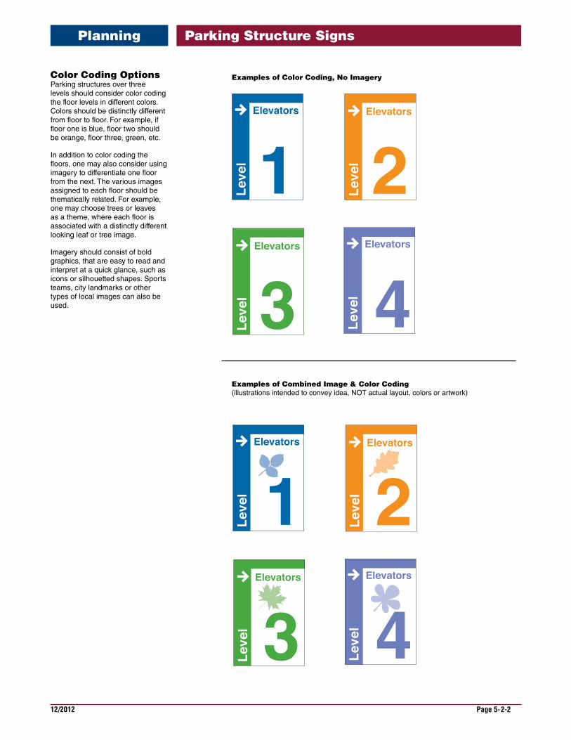
Color Coding Options Parking structures over three levels should consider color coding the floor levels in different colors. Colors should be distinctly different from floor to floor. For example, if floor one is blue, floor two should be orange, floor three, green, etc.
In addition to color coding the floors, one may also consider using imagery to differentiate one floor from the next. The various images assigned to each floor should be thematically related. For example, one may choose trees or leaves as a theme, where each floor is associated with a distinctly different looking leaf or tree image.
Imagery should consist of bold graphics, that are easy to read and interpret at a quick glance, such as icons or silhouetted shapes. Sports teams, city landmarks or other types of local images can also be used.
Examples of Color Coding, No Imagery
Examples of Combined Image & Color Coding(illustrations intended to convey idea, NOT actual layout, colors or artwork)
Planning Parking Structure Signs

12/2012 Page 5-3-1
The following are some general “Do’s and Don’ts” guidelines one can refer to when developing a sign program: this is not intended to be a training section of the guide, but to provide key information and suggestions that will hopefully reduce common errors that are made when planning and programming a parking structure sign program.
•Never use text smaller than 3” capital letter height when a sign is intended to be read from a moving vehicle.
•Text intended to be read by pedestrians should be a minimum of 1-1/2” capital letter height.
•Use text (words) which are familiar, easy to understand and comfortable to the viewer.
•Always use the same words, names or titles throughout the sign program.
•All sign messages need to be a minimum of 24” above grade.
•When selecting a background color for the signs, select a complementary color to the buildings on campus.
•Signs do require maintenance. Cleaning and waxing will extend the life of exte-rior signs.
•Always consider the landscaping surrounding a sign when determining a sign’s size. It is important that shrubs and other plants do not hide or obscure the sign.
•Lettering and sign panel size should be appropriate for the distance and speed at which a sign is viewed.
•Keep sign messages brief.
•Unnecessary information on signs can confuse the viewer.
•Typically, all signs, with the exception of directional signs, should convey no more than one concept or thought.
•Use text (words) that can be quickly read by the viewer. Use the same words throughout the sign program.
•On directional and informational signs provide only the information necessary to make a decision at that particular location.
•Whenever possible, messages should be presented using positive information.
•On directional signs, do not anticipate decisions that can be made later. Unnecessary or premature information will confuse the reader.
•Messages placed on signs should be concise, preferably with no more than seven to ten words.
•For signs to be read from a moving car, take into account the speed of the car. At a slow speed the driver may be able to read seven or eight words. At a faster speed they will only be able to read four or five.
General Guidelines
Size of Sign to Use
Message Content
Helpful Hints Parking Structure Signs
12/2012 Page 5-3-2
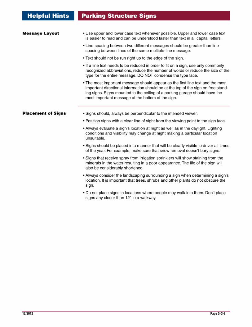
•Use upper and lower case text whenever possible. Upper and lower case text is easier to read and can be understood faster than text in all capital letters.
•Line-spacing between two different messages should be greater than line-spacing between lines of the same multiple-line message.
•Text should not be run right up to the edge of the sign.
•If a line text needs to be reduced in order to fit on a sign, use only commonly recognized abbreviations, reduce the number of words or reduce the size of the type for the entire message. DO NOT condense the type face.
•The most important message should appear as the first line text and the most important directional information should be at the top of the sign on free stand-ing signs. Signs mounted to the ceiling of a parking garage should have the most important message at the bottom of the sign.
•Signs should, always be perpendicular to the intended viewer.
•Position signs with a clear line of sight from the viewing point to the sign face.
•Always evaluate a sign's location at night as well as in the daylight. Lighting conditions and visibility may change at night making a particular location unsuitable.
•Signs should be placed in a manner that will be clearly visible to driver all times of the year. For example, make sure that snow removal doesn't bury signs.
•Signs that receive spray from irrigation sprinklers will show staining from the minerals in the water resulting in a poor appearance. The life of the sign will also be considerably shortened.
•Always consider the landscaping surrounding a sign when determining a sign's location. It is important that trees, shrubs and other plants do not obscure the sign.
•Do not place signs in locations where people may walk into them. Don't place signs any closer than 12" to a walkway.
Message Layout
Placement of Signs
Helpful Hints Parking Structure Signs
12/2012 Page 5-4-1
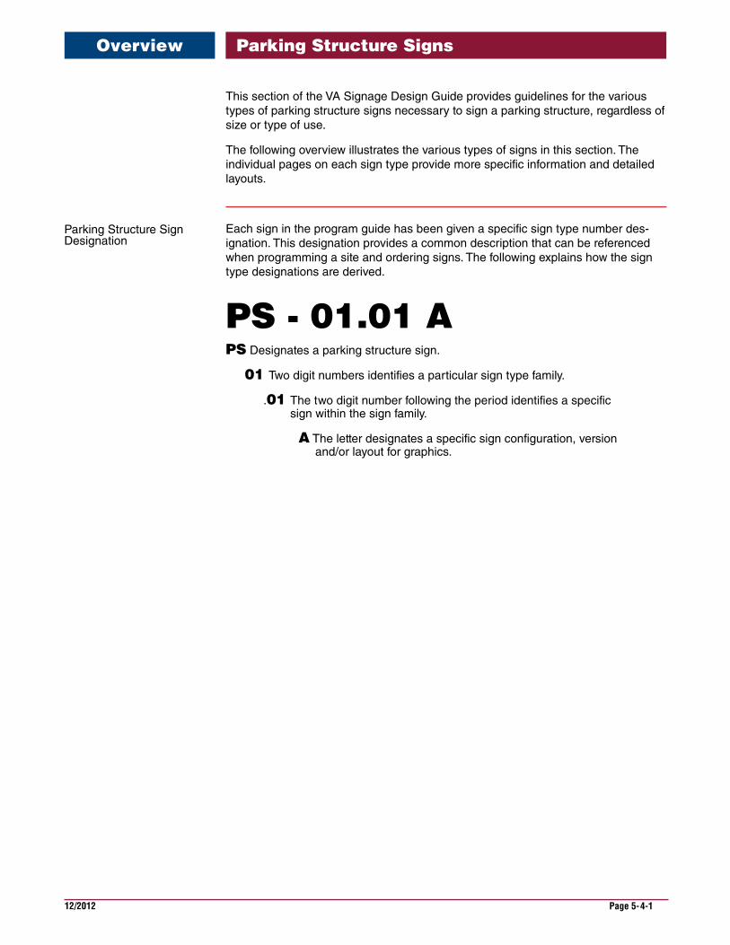
This section of the VA Signage Design Guide provides guidelines for the various types of parking structure signs necessary to sign a parking structure, regardless of size or type of use.
The following overview illustrates the various types of signs in this section. The individual pages on each sign type provide more specific information and detailed layouts.
Each sign in the program guide has been given a specific sign type number des-ignation. This designation provides a common description that can be referenced when programming a site and ordering signs. The following explains how the sign type designations are derived.
PS - 01.01 APS Designates a parking structure sign.
01 Two digit numbers identifies a particular sign type family.
.01 The two digit number following the period identifies a specific sign within the sign family.
A The letter designates a specific sign configuration, version and/or layout for graphics.
Overview Parking Structure Signs
Parking Structure Sign Designation
12/2012 Page 5-4-2
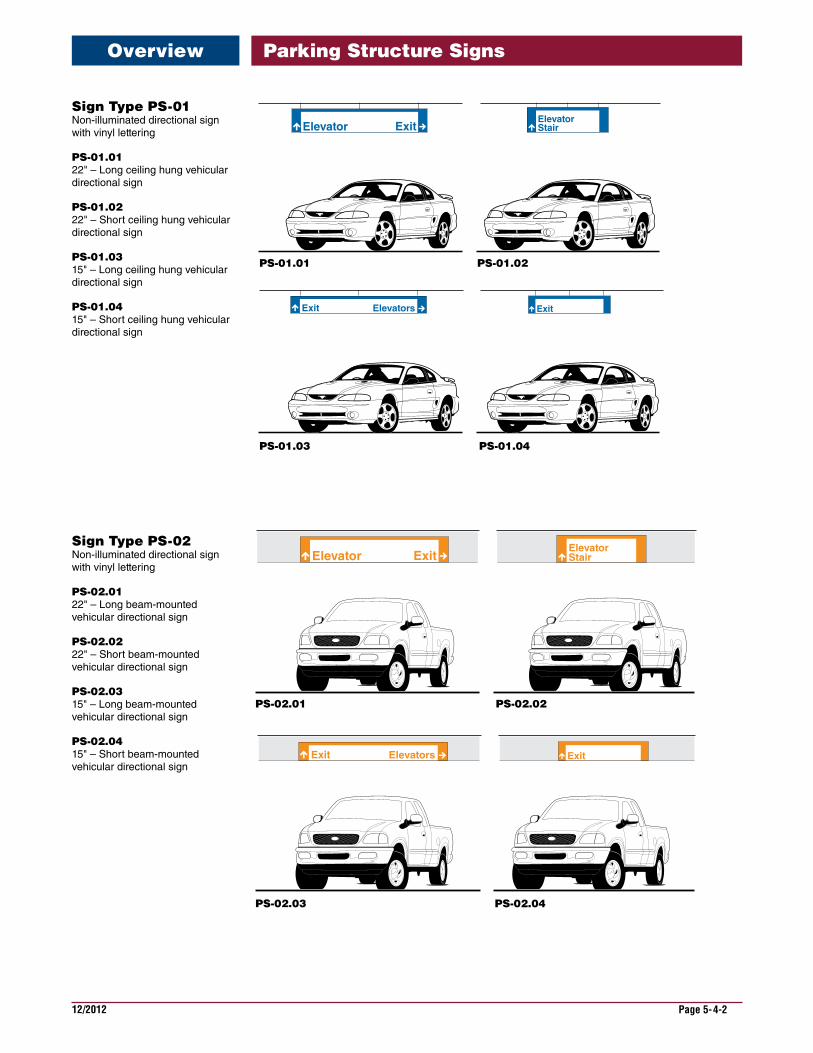
Sign Type PS-01 Non-illuminated directional sign with vinyl lettering
PS-01.01 22" – Long ceiling hung vehicular directional sign
PS-01.02 22" – Short ceiling hung vehicular directional sign
PS-01.03 15" – Long ceiling hung vehicular directional sign
PS-01.04 15" – Short ceiling hung vehicular directional sign
Elevator Exit StairElevator
ElevatorsExit Exit
PS-01.01
PS-01.03
Sign Type PS-02 Non-illuminated directional sign with vinyl lettering
PS-02.01 22" – Long beam-mounted vehicular directional sign
PS-02.02 22" – Short beam-mounted vehicular directional sign
PS-02.03 15" – Long beam-mounted vehicular directional sign
PS-02.04 15" – Short beam-mounted vehicular directional sign
ExitElevatorsExit
StairElevator
Elevator Exit
PS-02.01
PS-02.03
Overview Parking Structure Signs
PS-01.02
PS-01.04
PS-02.02
PS-02.04
12/2012 Page 5-4-3
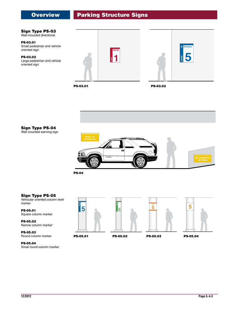
Sign Type PS-03 Wall-mounted directional
PS-03.01 Small pedestrian and vehicle oriented sign
PS-03.02 Large pedestrian and vehicle oriented sign
Sign Type PS-04 Wall mounted warning sign
Sign Type PS-05 Vehicular oriented column level marker
PS-05.01 Square column marker
PS-05.02 Narrow column marker
PS-05.03 Round column marker
PS-05.04 Small round column marker
5
So
uth
5
Lev
el
55North
PS-03.01
PS-04
PS-05.01
Watch forPedestriansWatch for
Pedestrians
Watch forPedestrians
No Pedestrianson Ramp
5Lev
el
Elevators
1Lev
el
North
Overview Parking Structure Signs
PS-03.02
PS-05.02 PS-05.03 PS-05.04
12/2012 Page 5-4-4
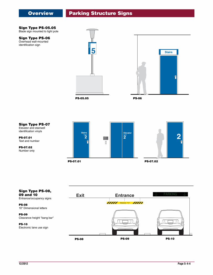
Sign Type PS-05.05 Blade sign mounted to light pole
Sign Type PS-06 Overhead wall-mounted identification sign
Sign Type PS-07 Elevator and stairwell identification vinyls
PS-07.01 Text and number
PS-07.02 Number only
Sign Type PS-08, 09 and 10 Entrance/occupancy signs
PS-08 10" Dimensional letters
PS-09 Clearance height "bang bar"
PS-10 Electronic lane use sign
PS-06
Stairs
IN CASE OF FIRE, USE S TAIRS. DO NOT USE ELEVATORS.
StairsLevel
2ElevatorLevel
2 2
PS-07.01 PS-07.02
5
So
uth
PS-05.05
Clearance 7'-0"
EntranceExit
PS-09 PS-10PS-08
Overview Parking Structure Signs
12/2012 Page 5-4-5
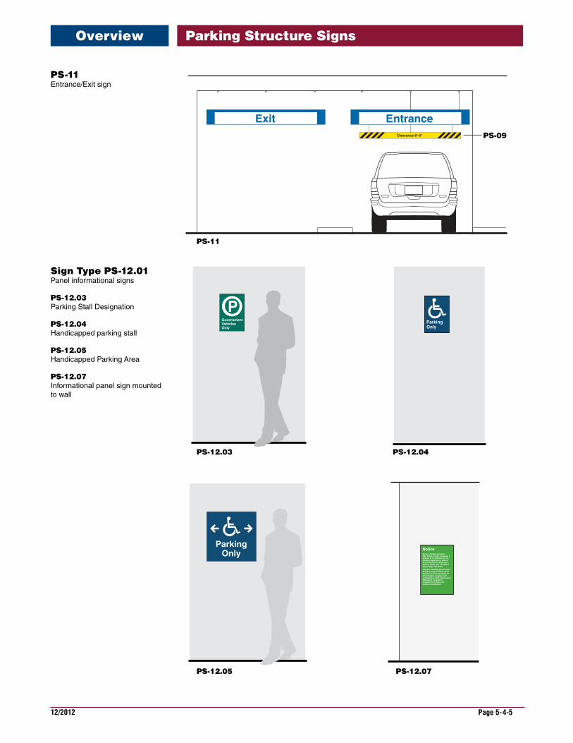
Sign Type PS-12.01 Panel informational signs
PS-12.03 Parking Stall Designation
PS-12.04 Handicapped parking stall
PS-12.05 Handicapped Parking Area
PS-12.07 Informational panel sign mounted to wall
ParkingOnly
PS-12.03
PS-12.05 PS-12.07
PS-12.04
Clearance 8'-0"
EntranceExit
PS-11
PS-09
PS-11 Entrance/Exit sign
Overview Parking Structure Signs
12/2012 Page 5-4-6
PS-14
PS-15
PS-13
Spaces Available
LEVEL 4
LEVEL 3
LEVEL 2
LEVEL 5
LEVEL 1
Entrance
Clearance 7'-0"
P
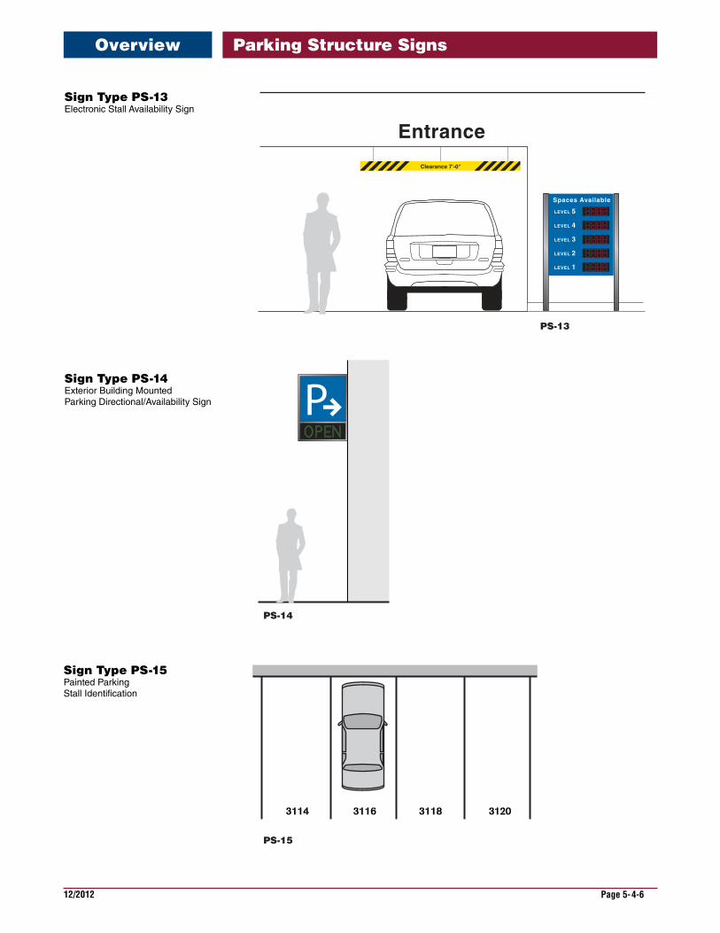
Sign Type PS-13 Electronic Stall Availability Sign
Sign Type PS-14 Exterior Building Mounted Parking Directional/Availability Sign
Sign Type PS-15 Painted Parking Stall Identification
Overview Parking Structure Signs

12/2012 Page 5-4-7
Parking Regulatory See Exterior Sign Section for more detail.
Informational Signs See Interior Sign Section for more detail.
ParkingOnly
ParkingForGovernmentEmployees
IN CASE OF FIRE, USE STAIRS. DO NOT USE ELEVATORS.
NOEXIT
44444
MechanicalRoom
Elevator
NOEXIT
Overview Parking Structure Signs
12/2012 Page 5-4-8
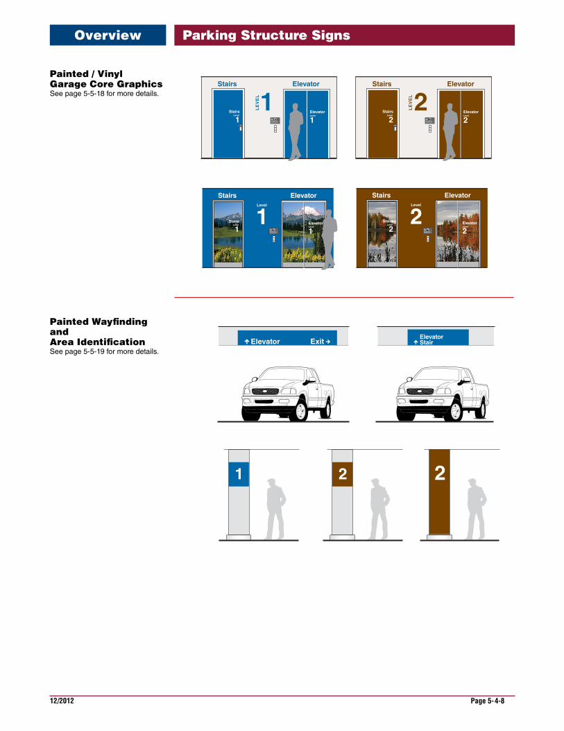
Painted / Vinyl Garage Core Graphics See page 5-5-18 for more details.
Painted Wayfinding and Area Identification See page 5-5-19 for more details.
1 2 2
StairElevator
Elevator Exit
IN CASE OF FIRE, USE STAIRS. DO NOT USE ELEVATORS.
1ElevatorStairs
LE
VE
L
IN CASE OF FIRE, USE STAIRS. DO NOT USE ELEVATORS.
2ElevatorStairs
LEV
EL
StairsLevel
2ElevatorLevel
2Stairs
Level
1ElevatorLevel
1
IN CASE OF FIRE, USE STAIRS. DO NOT USE ELEVATORS.
1ElevatorStairs
Level
ElevatorLevel
1Stairs
Level
1 IN CASE OF FIRE, USE STAIRS. DO NOT USE ELEVATORS.
2ElevatorStairs
Level
ElevatorLevel
2Stairs
Level
2
Overview Parking Structure Signs
12/2012 Page 5-5-1
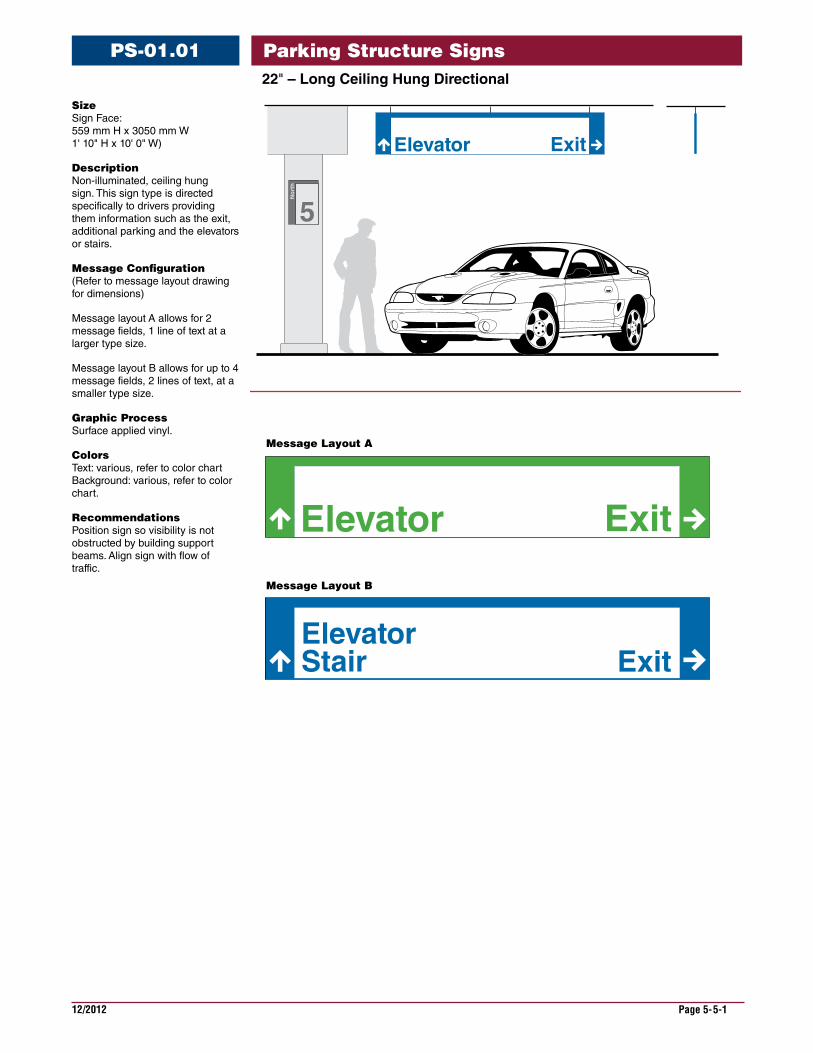
22"–LongCeilingHungDirectional
PS-01.01
Size Sign Face: 559 mm H x 3050 mm W 1' 10" H x 10' 0" W)
Description Non-illuminated, ceiling hung sign. This sign type is directed specifically to drivers providing them information such as the exit, additional parking and the elevators or stairs.
Message Configuration (Refer to message layout drawing for dimensions)
Message layout A allows for 2 message fields, 1 line of text at a larger type size.
Message layout B allows for up to 4 message fields, 2 lines of text, at a smaller type size.
Graphic Process Surface applied vinyl.
Colors Text: various, refer to color chart Background: various, refer to color chart.
Recommendations Position sign so visibility is not obstructed by building support beams. Align sign with flow of traffic.
5
No
rth
Elevator Exit
Elevator Exit
StairElevator
Exit
Message Layout B
Message Layout A
Parking Structure Signs
12/2012 Page 5-5-2
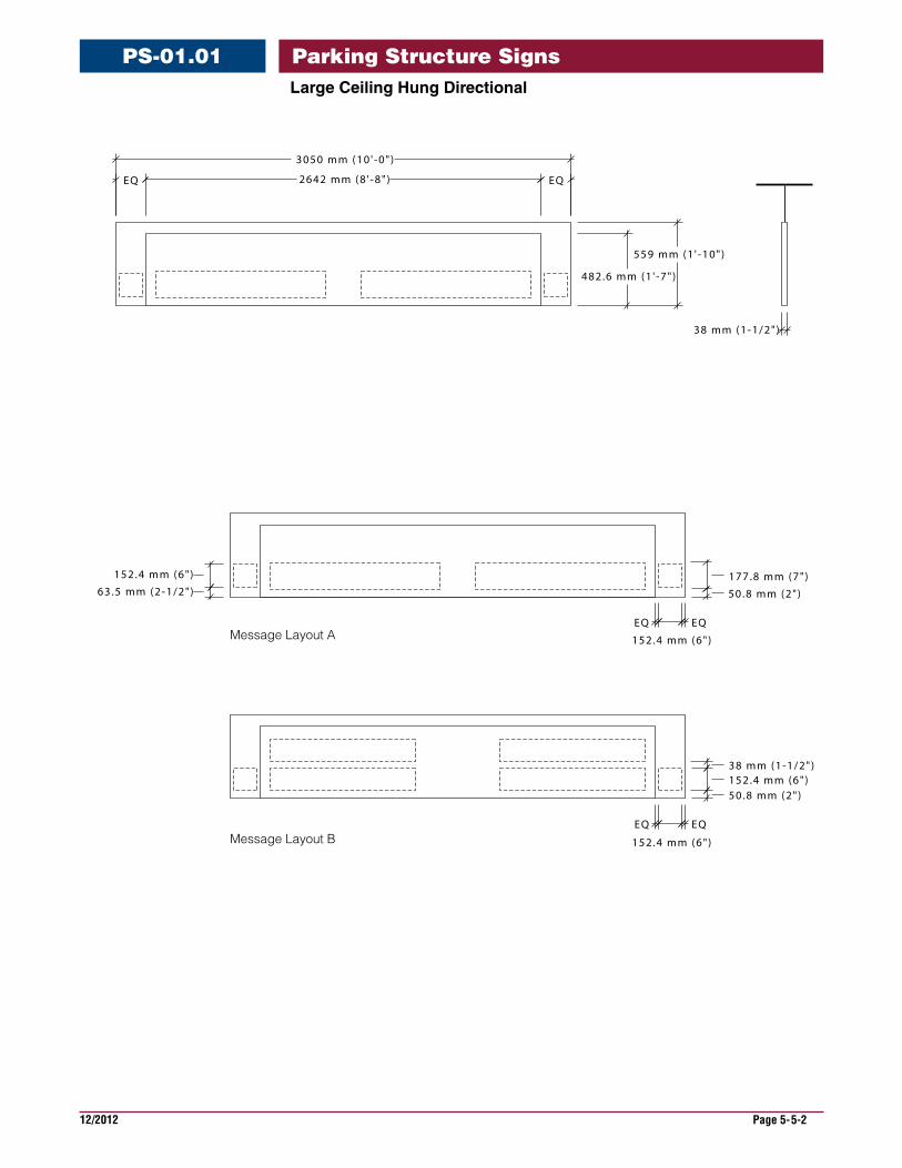
LargeCeilingHungDirectional
PS-01.01
38 mm (1-1/2")152.4 mm (6")50.8 mm (2")
EQ
152.4 mm (6")
EQ
177.8 mm (7")
50.8 mm (2")
152.4 mm (6")
63.5 mm (2-1/2")
EQ
152.4 mm (6")
EQMessage Layout A
Message Layout B
EQ 2642 mm (8 ' -8" ) EQ
3050 mm (10 ' -0" )
482.6 mm (1 ' -7" )
559 mm (1 ' -10")
38 mm (1-1/2")
Parking Structure Signs
12/2012 Page 5-5-3
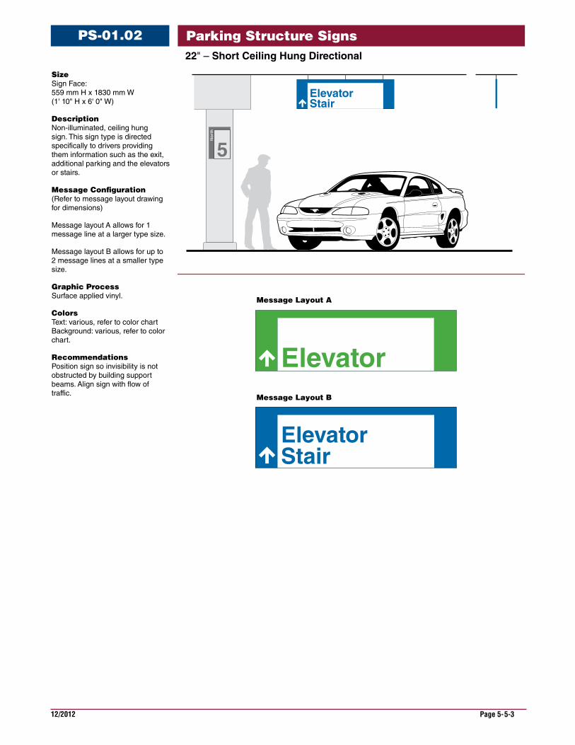
22"–ShortCeilingHungDirectional
PS-01.02
Size Sign Face: 559 mm H x 1830 mm W (1' 10" H x 6' 0" W)
Description Non-illuminated, ceiling hung sign. This sign type is directed specifically to drivers providing them information such as the exit, additional parking and the elevators or stairs.
Message Configuration (Refer to message layout drawing for dimensions)
Message layout A allows for 1 message line at a larger type size.
Message layout B allows for up to 2 message lines at a smaller type size.
Graphic Process Surface applied vinyl.
Colors Text: various, refer to color chart Background: various, refer to color chart.
Recommendations Position sign so invisibility is not obstructed by building support beams. Align sign with flow of traffic.
5
No
rth
StairElevator
Elevator
StairElevator
Message Layout A
Message Layout B
Parking Structure Signs
12/2012 Page 5-5-4
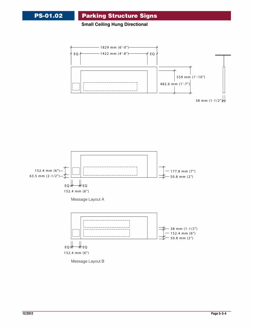
SmallCeilingHungDirectional
PS-01.02
38 mm (1-1/2")152.4 mm (6")50.8 mm (2")
EQ
152.4 mm (6")
EQ
177.8 mm (7")
50.8 mm (2")
152.4 mm (6")
63.5 mm (2-1/2")
EQ
152.4 mm (6")
EQ
EQ 1422 mm (4 ' -8" ) EQ
1829 mm (6 ' -0" )
482.6 mm (1 ' -7" )
559 mm (1 ' -10")
38 mm (1-1/2")
Message Layout A
Message Layout B
Parking Structure Signs
12/2012 Page 5-5-5
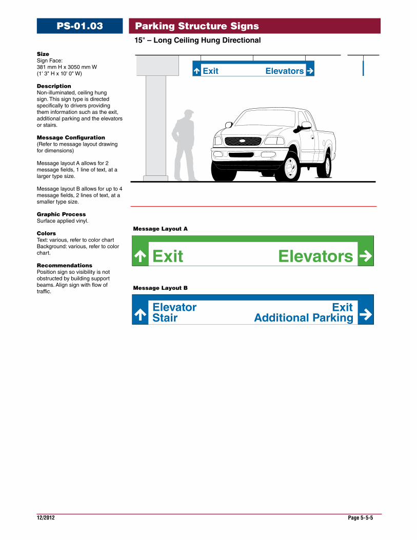
15"–LongCeilingHungDirectional
PS-01.03
Elevators
Stair Additional ParkingElevator Exit
Exit
Message Layout A
Message Layout B
Size Sign Face: 381 mm H x 3050 mm W (1' 3" H x 10' 0" W)
Description Non-illuminated, ceiling hung sign. This sign type is directed specifically to drivers providing them information such as the exit, additional parking and the elevators or stairs.
Message Configuration (Refer to message layout drawing for dimensions)
Message layout A allows for 2 message fields, 1 line of text, at a larger type size.
Message layout B allows for up to 4 message fields, 2 lines of text, at a smaller type size.
Graphic Process Surface applied vinyl.
Colors Text: various, refer to color chart Background: various, refer to color chart.
Recommendations Position sign so visibility is not obstructed by building support beams. Align sign with flow of traffic.
Parking Structure Signs
12/2012 Page 5-5-6
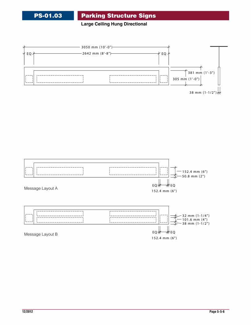
LargeCeilingHungDirectional
PS-01.03
152.4 mm (6")50.8 mm (2")
EQ
152.4 mm (6")
EQ
32 mm (1-1/4")101.6 mm (4")38 mm (1-1/2")
EQ
152.4 mm (6")
EQ
EQ 2642 mm (8 ' -8" ) EQ
3050 mm (10 ' -0" )
305 mm (1 ' -0" )
381 mm (1 ' -3" )
38 mm (1-1/2")
Message Layout A
Message Layout B
Parking Structure Signs
12/2012 Page 5-5-7
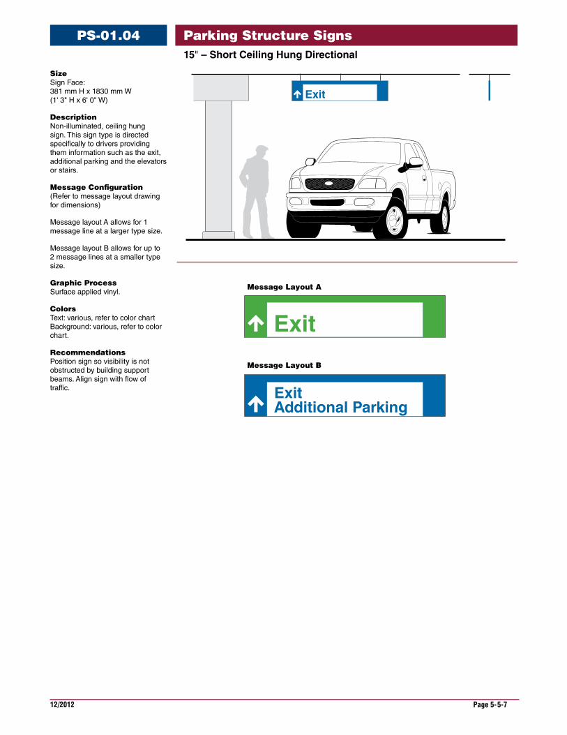
15"–ShortCeilingHungDirectional
PS-01.04
Exit
Exit
ExitAdditional Parking
Message Layout A
Message Layout B
Size Sign Face: 381 mm H x 1830 mm W (1' 3" H x 6' 0" W)
Description Non-illuminated, ceiling hung sign. This sign type is directed specifically to drivers providing them information such as the exit, additional parking and the elevators or stairs.
Message Configuration (Refer to message layout drawing for dimensions)
Message layout A allows for 1 message line at a larger type size.
Message layout B allows for up to 2 message lines at a smaller type size.
Graphic Process Surface applied vinyl.
Colors Text: various, refer to color chart Background: various, refer to color chart.
Recommendations Position sign so visibility is not obstructed by building support beams. Align sign with flow of traffic.
Parking Structure Signs
12/2012 Page 5-5-8
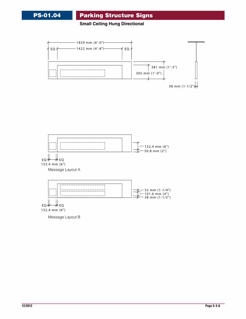
SmallCeilingHungDirectional
PS-01.04
152.4 mm (6")50.8 mm (2")
EQ152.4 mm (6")
EQ
32 mm (1-1/4")101.6 mm (4")38 mm (1-1/2")
EQ152.4 mm (6")
EQ
305 mm (1 ' -0" )
381 mm (1 ' -3" )
38 mm (1-1/2")
EQ 1422 mm (4 ' -8" ) EQ
1829 mm (6 ' -0" )
Message Layout A
Message Layout B
Parking Structure Signs
12/2012 Page 5-5-9
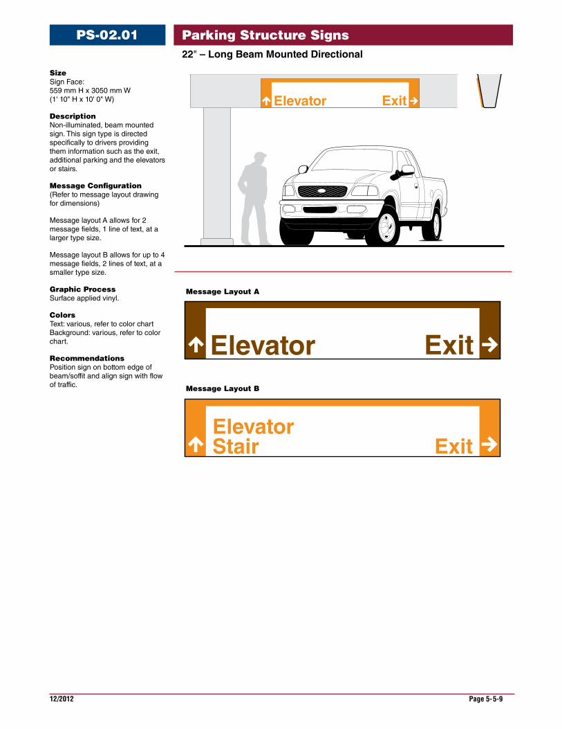
22"–LongBeamMountedDirectional
PS-02.01
Size Sign Face: 559 mm H x 3050 mm W (1' 10" H x 10' 0" W)
Description Non-illuminated, beam mounted sign. This sign type is directed specifically to drivers providing them information such as the exit, additional parking and the elevators or stairs.
Message Configuration (Refer to message layout drawing for dimensions)
Message layout A allows for 2 message fields, 1 line of text, at a larger type size.
Message layout B allows for up to 4 message fields, 2 lines of text, at a smaller type size.
Graphic Process Surface applied vinyl.
Colors Text: various, refer to color chart Background: various, refer to color chart.
Recommendations Position sign on bottom edge of beam/soffit and align sign with flow of traffic.
StairElevator
Exit
Elevator Exit
Elevator Exit
Message Layout A
Message Layout B
Parking Structure Signs
12/2012 Page 5-5-10
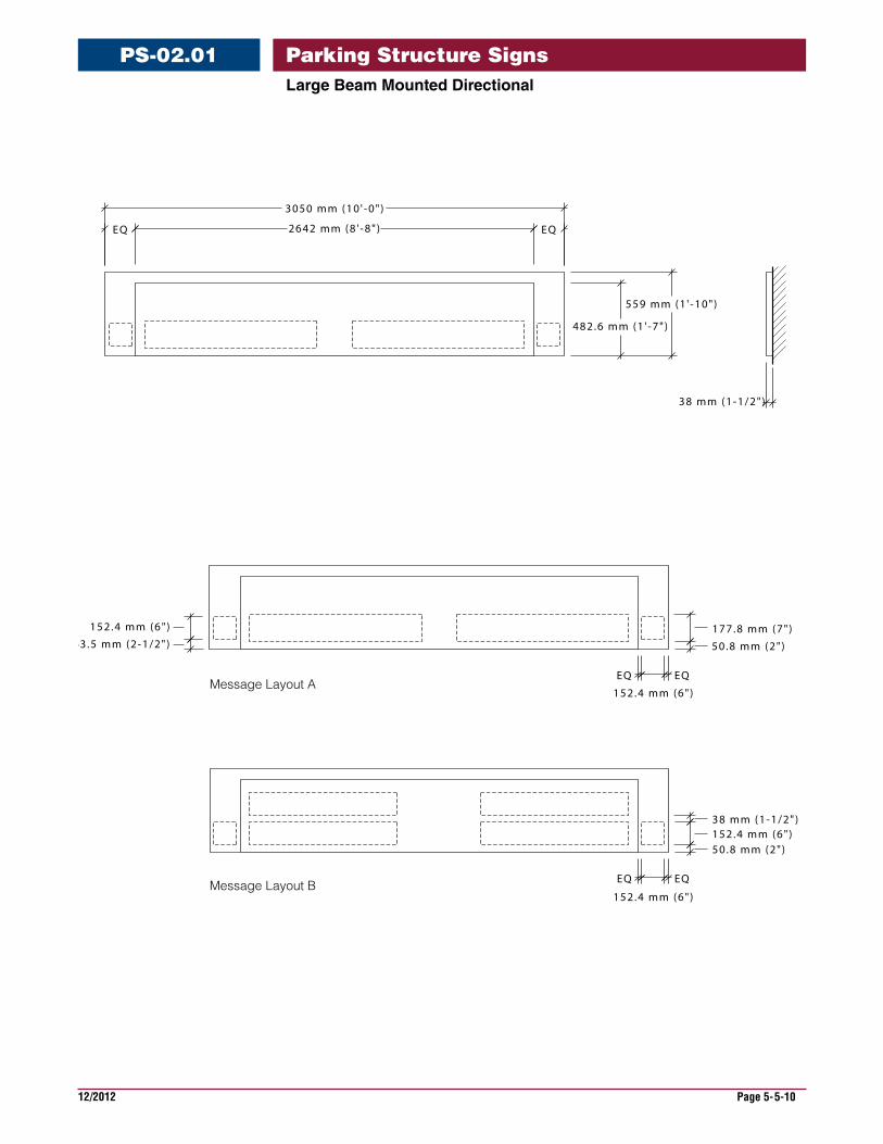
LargeBeamMountedDirectional
PS-02.01
38 mm (1-1/2")152.4 mm (6")50.8 mm (2")
177.8 mm (7")
50.8 mm (2")
152.4 mm (6")
63.5 mm (2-1/2")
EQ
152.4 mm (6")
EQ
EQ
152.4 mm (6")
EQ
EQ 2642 mm (8 ' -8" ) EQ
3050 mm (10 ' -0" )
482.6 mm (1 ' -7" )
559 mm (1 ' -10")
38 mm (1-1/2")
Message Layout A
Message Layout B
Parking Structure Signs
12/2012 Page 5-5-11
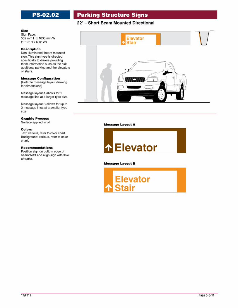
22"–ShortBeamMountedDirectional
PS-02.02
Size Sign Face: 559 mm H x 1830 mm W (1' 10" H x 6' 0" W)
Description Non-illuminated, beam mounted sign. This sign type is directed specifically to drivers providing them information such as the exit, additional parking and the elevators or stairs.
Message Configuration (Refer to message layout drawing for dimensions)
Message layout A allows for 1 message line at a larger type size.
Message layout B allows for up to 2 message lines at a smaller type size.
Graphic Process Surface applied vinyl.
Colors Text: various, refer to color chart Background: various, refer to color chart.
Recommendations Position sign on bottom edge of beam/soffit and align sign with flow of traffic.
StairElevator
Elevator
StairElevator
Message Layout A
Message Layout B
Parking Structure Signs
12/2012 Page 5-5-12
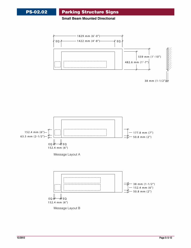
SmallBeamMountedDirectional
PS-02.02
177.8 mm (7")
50.8 mm (2")
152.4 mm (6")
63.5 mm (2-1/2")
EQ152.4 mm (6")
EQ
38 mm (1-1/2")152.4 mm (6")50.8 mm (2")
EQ152.4 mm (6")
EQ
482.6 mm (1 ' -7" )
559 mm (1 ' -10")
38 mm (1-1/2")
EQ 1422 mm (4 ' -8" ) EQ
1829 mm (6 ' -0" )
Message Layout A
Message Layout B
Parking Structure Signs
12/2012 Page 5-5-13
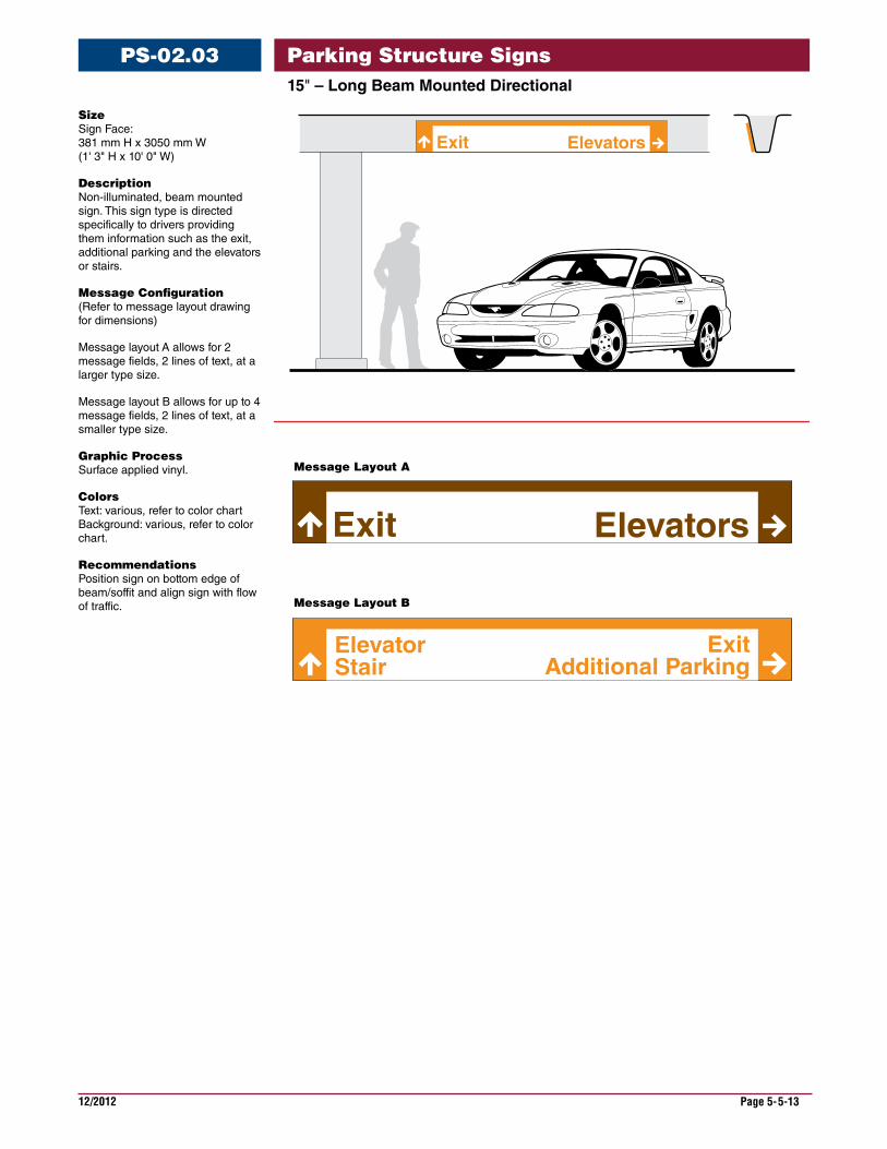
15"–LongBeamMountedDirectional
PS-02.03
ElevatorsExit
Elevators
Stair Additional ParkingElevator Exit
Exit
Message Layout A
Message Layout B
Size Sign Face: 381 mm H x 3050 mm W (1' 3" H x 10' 0" W)
Description Non-illuminated, beam mounted sign. This sign type is directed specifically to drivers providing them information such as the exit, additional parking and the elevators or stairs.
Message Configuration (Refer to message layout drawing for dimensions)
Message layout A allows for 2 message fields, 2 lines of text, at a larger type size.
Message layout B allows for up to 4 message fields, 2 lines of text, at a smaller type size.
Graphic Process Surface applied vinyl.
Colors Text: various, refer to color chart Background: various, refer to color chart.
Recommendations Position sign on bottom edge of beam/soffit and align sign with flow of traffic.
Parking Structure Signs
12/2012 Page 5-5-14
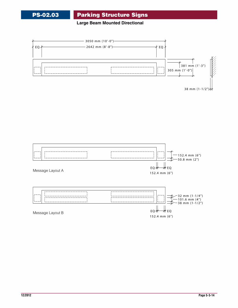
LargeBeamMountedDirectional
PS-02.03
152.4 mm (6")50.8 mm (2")
EQ
152.4 mm (6")
EQ
32 mm (1-1/4")101.6 mm (4")38 mm (1-1/2")
EQ
152.4 mm (6")
EQ
EQ 2642 mm (8 ' -8" ) EQ
3050 mm (10 ' -0" )
305 mm (1 ' -0" )381 mm (1 ' -3" )
38 mm (1-1/2")
Message Layout A
Message Layout B
Parking Structure Signs
12/2012 Page 5-5-15
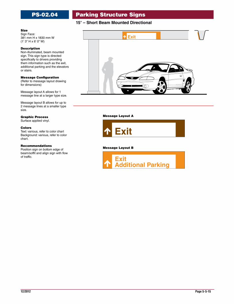
15"–ShortBeamMountedDirectional
PS-02.04
Size Sign Face: 381 mm H x 1830 mm W (1' 3" H x 6' 0" W)
Description Non-illuminated, beam mounted sign. This sign type is directed specifically to drivers providing them information such as the exit, additional parking and the elevators or stairs.
Message Configuration (Refer to message layout drawing for dimensions)
Message layout A allows for 1 message line at a larger type size.
Message layout B allows for up to 2 message lines at a smaller type size.
Graphic Process Surface applied vinyl.
Colors Text: various, refer to color chart Background: various, refer to color chart.
Recommendations Position sign on bottom edge of beam/soffit and align sign with flow of traffic.
Exit
Exit
ExitAdditional Parking
Message Layout A
Message Layout B
Parking Structure Signs
12/2012 Page 5-5-16
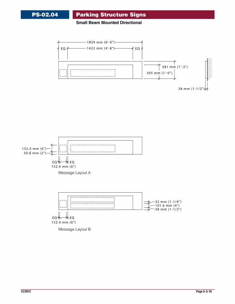
SmallBeamMountedDirectional
PS-02.04
152.4 mm (6")50.8 mm (2")
EQ152.4 mm (6")EQ
EQ152.4 mm (6")EQ
32 mm (1-1/4")101.6 mm (4")38 mm (1-1/2")
305 mm (1 ' -0" )
381 mm (1 ' -3" )
38 mm (1-1/2")
EQ 1422 mm (4 ' -8" ) EQ
1829 mm (6 ' -0" )
Message Layout A
Message Layout B
Parking Structure Signs
12/2012 Page 5-5-17
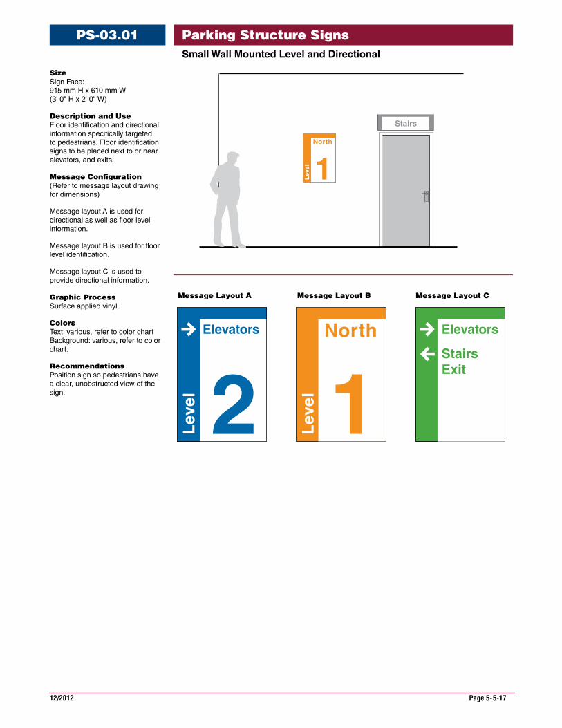
SmallWallMountedLevelandDirectional
PS-03.01
Size Sign Face: 915 mm H x 610 mm W (3' 0" H x 2' 0" W)
Description and Use Floor identification and directional information specifically targeted to pedestrians. Floor identification signs to be placed next to or near elevators, and exits.
Message Configuration (Refer to message layout drawing for dimensions)
Message layout A is used for directional as well as floor level information.
Message layout B is used for floor level identification.
Message layout C is used to provide directional information.
Graphic Process Surface applied vinyl.
Colors Text: various, refer to color chart Background: various, refer to color chart.
Recommendations Position sign so pedestrians have a clear, unobstructed view of the sign. 2L
evel
Elevators
1Lev
elNorth Elevators
StairsExit
1Lev
el
North
Message Layout A Message Layout B Message Layout C
Stairs
Parking Structure Signs
12/2012 Page 5-5-18
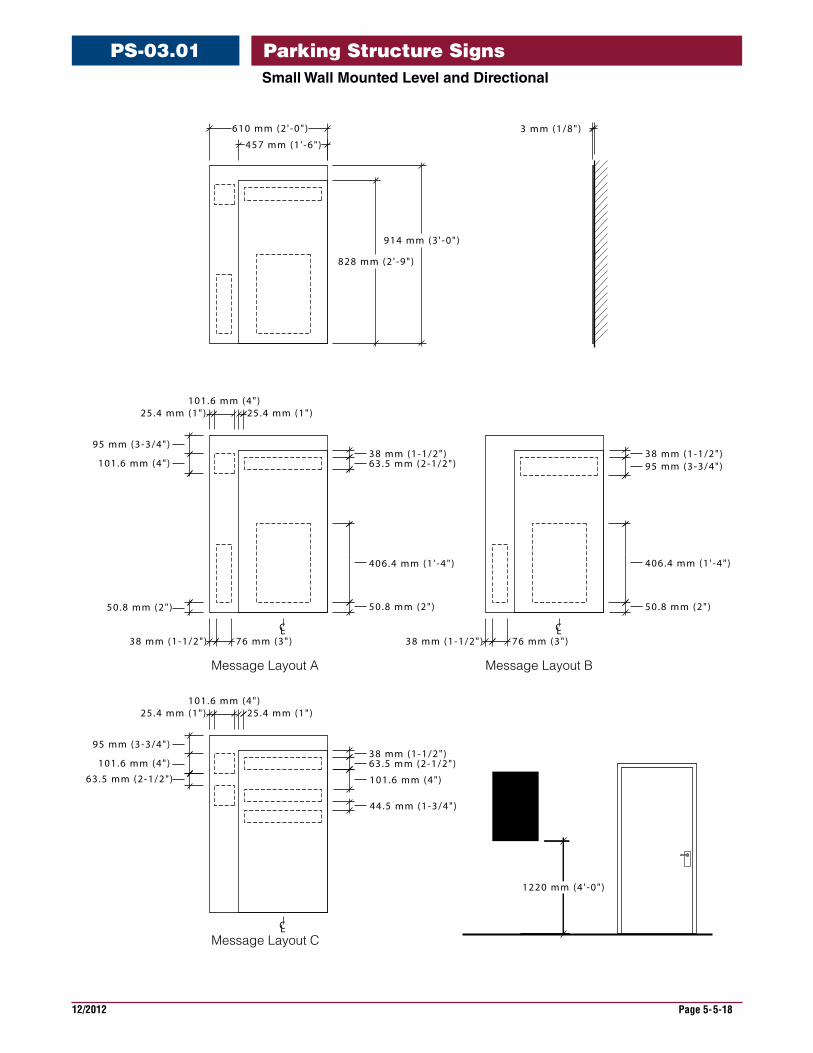
SmallWallMountedLevelandDirectional
PS-03.01
CL
457 mm (1 ' -6" )
610 mm (2 ' -0" )
25.4 mm (1")101.6 mm (4")
25.4 mm (1")
38 mm (1-1/2")63.5 mm (2-1/2")
406.4 mm (1 ' -4" )
50.8 mm (2")
828 mm (2 ' -9" )
914 mm (3 ' -0" )
95 mm (3-3/4")
101.6 mm (4")
50.8 mm (2")
25.4 mm (1")101.6 mm (4")
38 mm (1-1/2")63.5 mm (2-1/2")
95 mm (3-3/4")
101.6 mm (4")
63.5 mm (2-1/2")
38 mm (1-1/2") 76 mm (3")
38 mm (1-1/2")95 mm (3-3/4")
406.4 mm (1 ' -4" )
50.8 mm (2")
38 mm (1-1/2") 76 mm (3")
101.6 mm (4")
44.5 mm (1-3/4")
3 mm (1/8")
CL CL
25.4 mm (1")
1220 mm (4 ' -0" )
Message Layout A
Message Layout C
Message Layout B
Parking Structure Signs
12/2012 Page 5-5-19
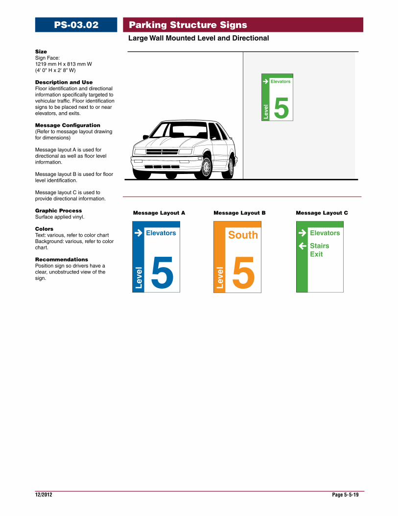
LargeWallMountedLevelandDirectional
PS-03.02
Size Sign Face: 1219 mm H x 813 mm W (4' 0" H x 2' 8" W)
Description and Use Floor identification and directional information specifically targeted to vehicular traffic. Floor identification signs to be placed next to or near elevators, and exits.
Message Configuration (Refer to message layout drawing for dimensions)
Message layout A is used for directional as well as floor level information.
Message layout B is used for floor level identification.
Message layout C is used to provide directional information.
Graphic Process Surface applied vinyl.
Colors Text: various, refer to color chart Background: various, refer to color chart.
Recommendations Position sign so drivers have a clear, unobstructed view of the sign. 5L
evel
Elevators
5Lev
el
Elevators
5Lev
el
South Elevators
StairsExit
Message Layout A Message Layout B Message Layout C
Parking Structure Signs
12/2012 Page 5-5-20
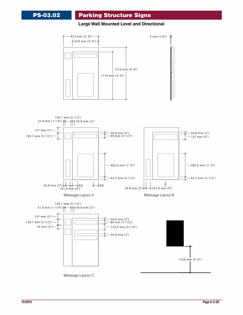
LargeWallMountedLevelandDirectional
PS-03.02
610 mm (2 ' -0" )
813 mm (2 ' -8" )
31.8 mm (1 1/4")139.7 mm (5-1/2")
50.8 mm (2")89 mm (3-1/2")
482.6 mm (1 ' -9" )
63.5 mm (2-1/2")
1118 mm (3 ' -8" )
1219 mm (4 ' -0" )
127 mm (5")
139.7 mm (5-1/2")
31.8 mm (1-1/4")139.7 mm (5-1/2")
50.8 mm (2")89 mm (3-1/2")
127 mm (5")
139.7 mm (5-1/2")
76 mm (3")
50.8 mm (2") 101.6 mm (4")EQEQ
101.6 mm (4")50.8 mm (2")
50.8 mm (2")127 mm (5")
482.6 mm (1 ' -9" )
63.5 mm (2-1/2")
133.4 mm (5-1/4")
50.8 mm (2")
3 mm (1/8")
CL
50.8 mm (2")
50.8 mm (2")
1220 mm (4 ' -0" )
Message Layout A
Message Layout C
Message Layout B
Parking Structure Signs
12/2012 Page 5-5-21
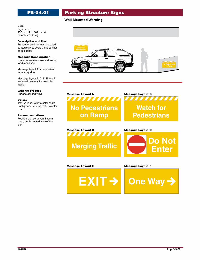
PS-04.01
Do NotEnter
One WayEXIT
No Pedestrianson Ramp
Merging Traffic
Watch forPedestrians
Message Layout A Message Layout B
Message Layout C Message Layout D
Message Layout E Message Layout F
Watch forPedestriansWatch for
Pedestrians
No Pedestrianson Ramp
Size Sign Face: 457 mm H x 1067 mm W (1' 6" H x 3' 3" W)
Description and Use Precautionary information placed strategically to avoid traffic conflict or accidents.
Message Configuration (Refer to message layout drawing for dimensions)
Message layout A is pedestrian regulatory sign.
Message layout B, C, D, E and F are used primarily for vehicular traffic.
Graphic Process Surface applied vinyl.
Colors Text: various, refer to color chart Background: various, refer to color chart.
Recommendations Position sign so drivers have a clear, unobstructed view of the sign.
WallMountedWarning
Parking Structure Signs
12/2012 Page 5-5-22
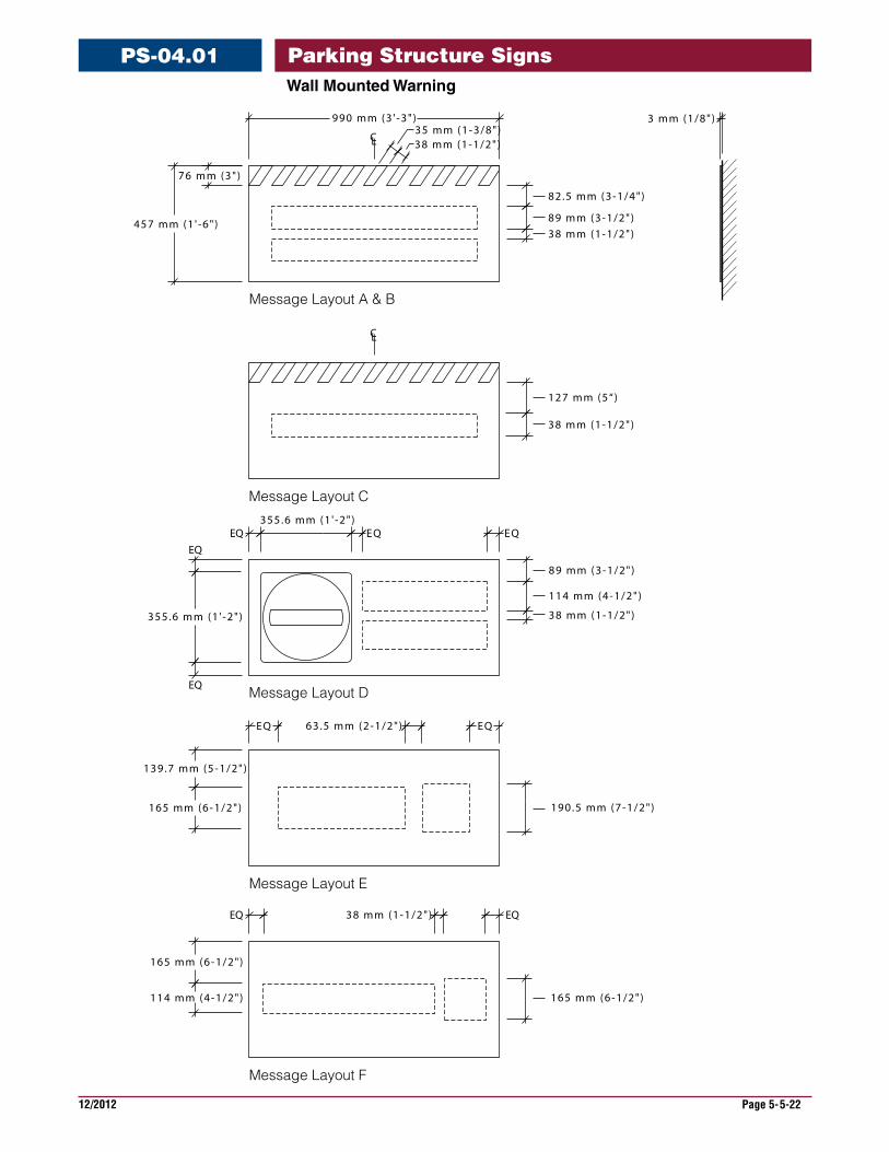
WallMountedWarning
PS-04.01
3 mm (1/8")
76 mm (3")
457 mm (1 ' -6" )
38 mm (1-1/2")35 mm (1-3/8")
82.5 mm (3-1/4")
89 mm (3-1/2")38 mm (1-1/2")
990 mm (3 ' -3" )
127 mm (5“)
38 mm (1-1/2")
EQ355.6 mm (1 ' -2" )
EQ EQEQ
355.6 mm (1 ' -2" )
EQ
89 mm (3-1/2")
114 mm (4-1/2")
38 mm (1-1/2")
EQ 63.5 mm (2-1/2") EQ
190.5 mm (7-1/2")
139.7 mm (5-1/2")
165 mm (6-1/2")
165 mm (6-1/2")
114 mm (4-1/2") 165 mm (6-1/2")
EQ 38 mm (1-1/2") EQ
CL
CL
Message Layout A & B
Message Layout C
Message Layout D
Message Layout E
Message Layout F
Parking Structure Signs
12/2012 Page 5-5-23
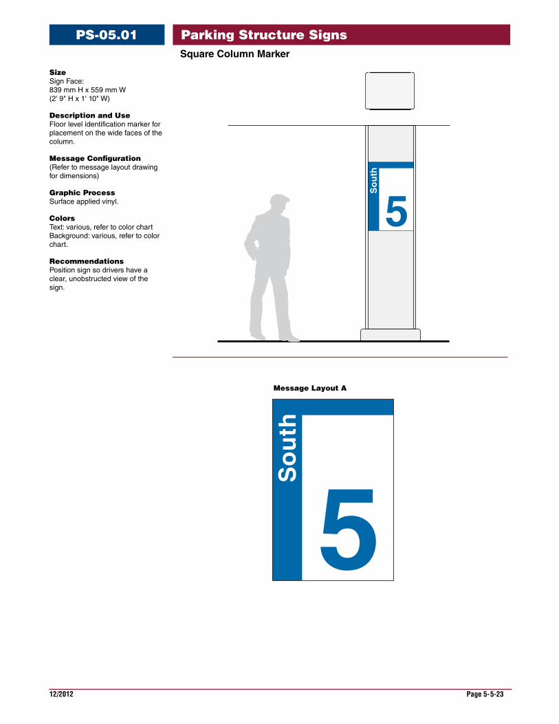
SquareColumnMarker
PS-05.01
5
So
uth
5
So
uth
Message Layout A
Size Sign Face: 839 mm H x 559 mm W (2' 9" H x 1' 10" W)
Description and Use Floor level identification marker for placement on the wide faces of the column.
Message Configuration (Refer to message layout drawing for dimensions)
Graphic Process Surface applied vinyl.
Colors Text: various, refer to color chart Background: various, refer to color chart.
Recommendations Position sign so drivers have a clear, unobstructed view of the sign.
Parking Structure Signs
12/2012 Page 5-5-24
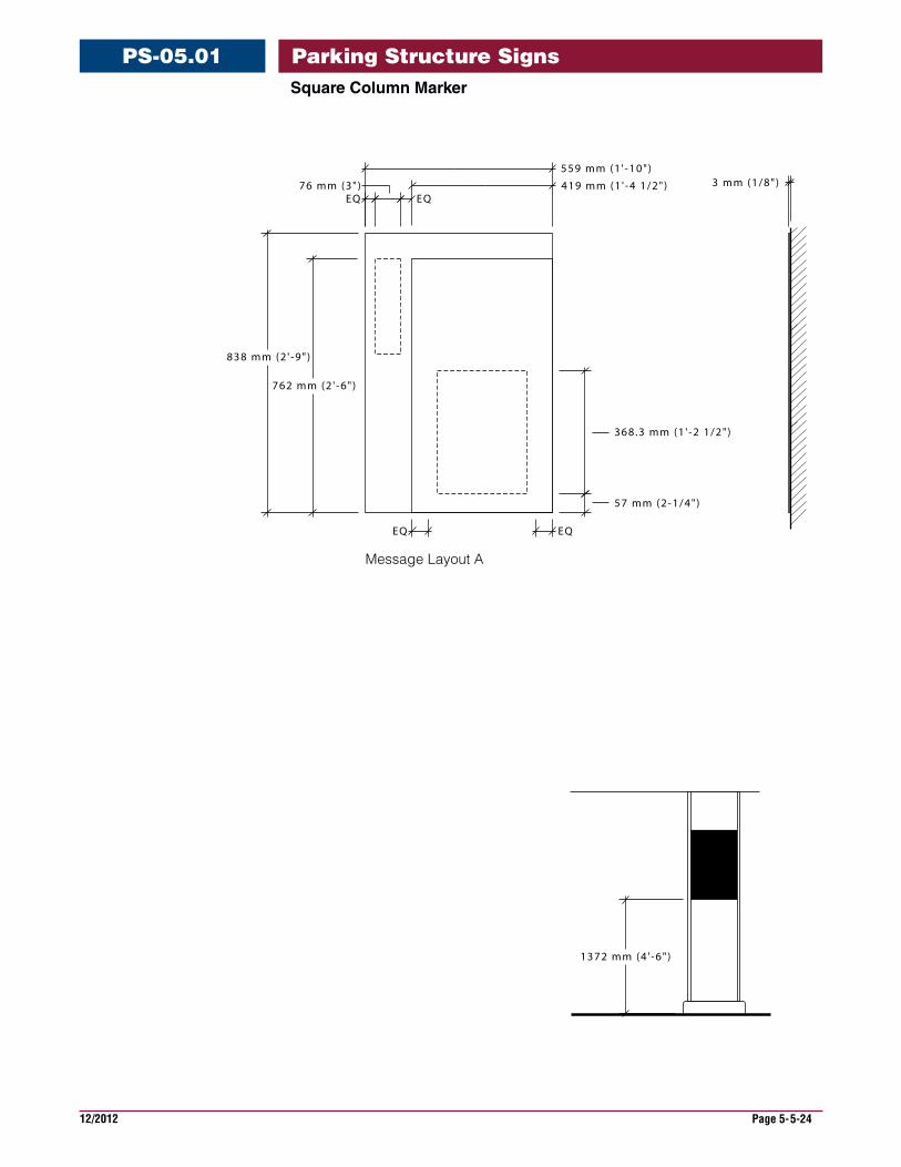
SquareColumnMarker
PS-05.01
3 mm (1/8")
EQ EQ
368.3 mm (1 ' -2 1/2")
57 mm (2-1/4")
419 mm (1 ' -4 1/2")
559 mm (1 ' -10")
EQ76 mm (3")
EQ
762 mm (2 ' -6" )
838 mm (2 ' -9" )
1372 mm (4 ' -6" )
Message Layout A
Parking Structure Signs
12/2012 Page 5-5-25
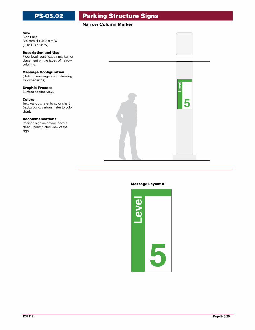
NarrowColumnMarker
PS-05.02
5
Lev
el
5
Lev
elMessage Layout A
Size Sign Face: 839 mm H x 407 mm W (2' 9" H x 1' 4" W)
Description and Use Floor level identification marker for placement on the faces of narrow columns.
Message Configuration (Refer to message layout drawing for dimensions)
Graphic Process Surface applied vinyl.
Colors Text: various, refer to color chart Background: various, refer to color chart.
Recommendations Position sign so drivers have a clear, unobstructed view of the sign.
Parking Structure Signs
12/2012 Page 5-5-26
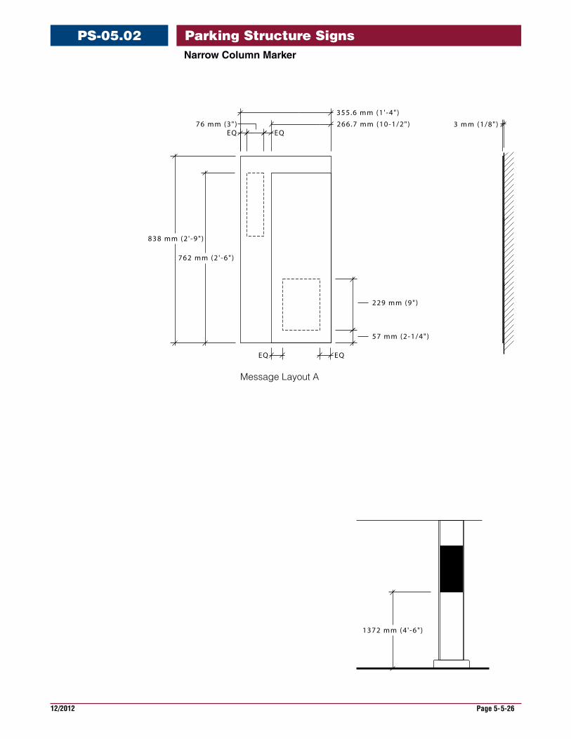
NarrowColumnMarker
PS-05.02
3 mm (1/8")266.7 mm (10-1/2")
355.6 mm (1 ' -4" )
EQ76 mm (3")
EQ
229 mm (9")
57 mm (2-1/4")
1372 mm (4 ' -6" )
762 mm (2 ' -6" )
838 mm (2 ' -9" )
EQ EQ
Message Layout A
Parking Structure Signs

12/2012 Page 5-5-27
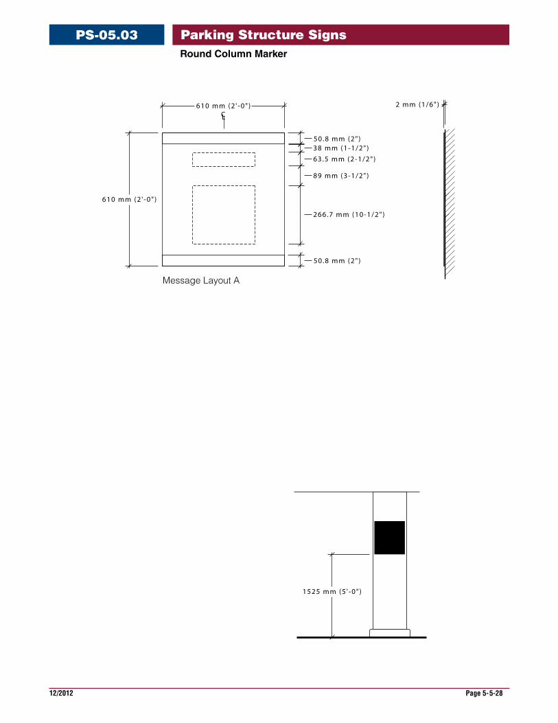
RoundColumnMarker
PS-05.03
5North
Message Layout A
Size Sign Face: 610 mm H x 610 mm W (2' 0" H x 2' 0" W)
Description and Use Floor level identification marker for placement on round columns.
Message Configuration (Refer to message layout drawing for dimensions)
Graphic Process Surface applied vinyl.
Colors Text: various, refer to color chart Background: various, refer to color chart.
Recommendations Position sign so drivers have a clear, unobstructed view of the sign.
Parking Structure Signs
12/2012 Page 5-5-28
RoundColumnMarker
PS-05.03
2 mm (1/6")
1525 mm (5 ' -0" )
38 mm (1-1/2")63.5 mm (2-1/2")
89 mm (3-1/2")
266.7 mm (10-1/2")
50.8 mm (2")
50.8 mm (2")
610 mm (2 ' -0" )
610 mm (2 ' -0" )CL
Message Layout A
Parking Structure Signs
12/2012 Page 5-5-29
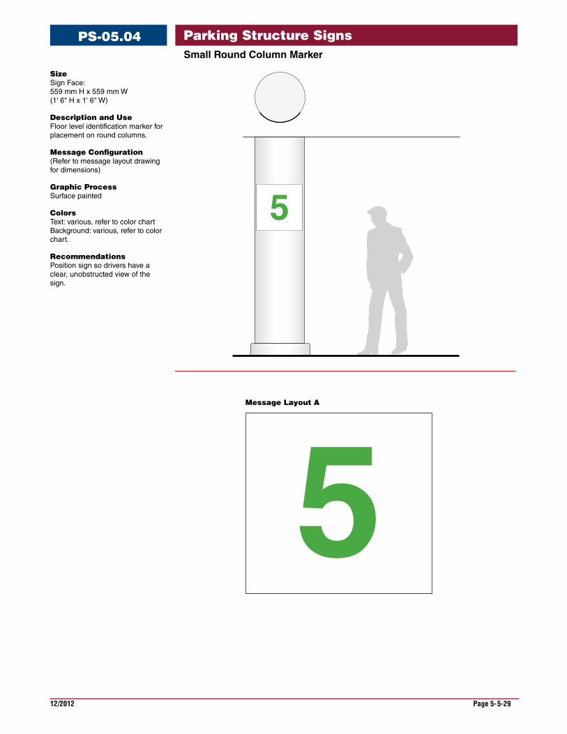
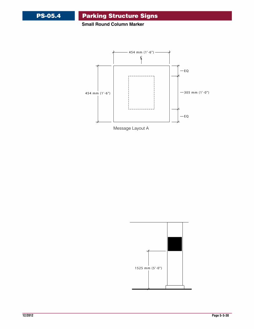
SmallRoundColumnMarker
PS-05.04
5
Message Layout A
Size Sign Face: 559 mm H x 559 mm W (1' 6" H x 1' 6" W)
Description and Use Floor level identification marker for placement on round columns.
Message Configuration (Refer to message layout drawing for dimensions)
Graphic Process Surface painted
Colors Text: various, refer to color chart Background: various, refer to color chart.
Recommendations Position sign so drivers have a clear, unobstructed view of the sign.
Parking Structure Signs
12/2012 Page 5-5-30
SmallRoundColumnMarker
PS-05.4
CL
1525 mm (5 ' -0" )
454 mm (1 ' -6" )
454 mm (1 ' -6" )
EQ
305 mm (1 ' -0" )
EQ
Message Layout A
Parking Structure Signs

12/2012 Page 5-5-31
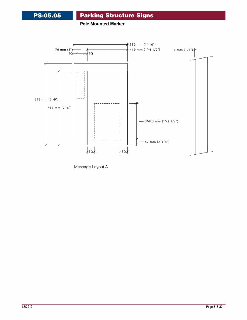
PoleMountMarker
PS-05.05
Size Sign Face: 839 mm H x 559 mm W (2' 9" H x 1' 10" W)
Description Floor Level identification marker for placement on pole.
Message Configuration (Refer to message layout drawing for dimensions)
Graphic Process Surface applied vinyl.
Colors Text: various, refer to color chart Background: various, refer to color chart.
Recommendations Position sign so drivers have a clear, unobstructed view of the sign.
5
So
uth
5
So
uth
5
So
uth
Sign Mounted in Front and Back of Pole
Single Flag Mounted Sign
5S
ou
th
5S
ou
th
Double Flag Mounted Sign
Message Layout A
Parking Structure Signs
12/2012 Page 5-5-32
PoleMountedMarker
PS-05.05
368.3 mm (1 ' -2 1/2")
57 mm (2-1/4")
419 mm (1 ' -4 1/2")
559 mm (1 ' -10")
EQ76 mm (3")
EQ
762 mm (2 ' -6" )
838 mm (2 ' -9" )
3 mm (1/8")
EQ EQ
Message Layout A
Parking Structure Signs
12/2012 Page 5-5-33
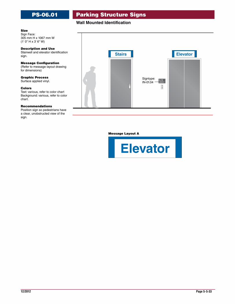
WallMountedIdentification
PS-06.01
Signtype:IN-01.04 IN CASE OF FIRE,
USE STAIRS. DO NOT USE ELEVATORS.
Elevator
Stairs Elevator
Message Layout A
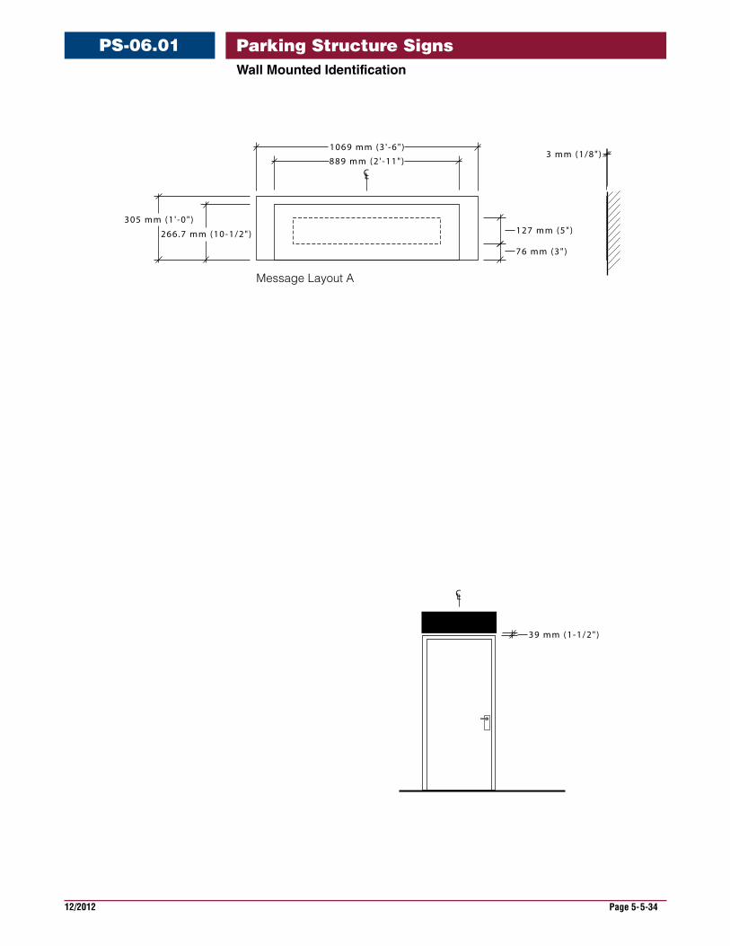
Size Sign Face: 305 mm H x 1067 mm W (1' 0" H x 3' 6" W)
Description and Use Stairwell and elevator identification sign.
Message Configuration (Refer to message layout drawing for dimensions)
Graphic Process Surface applied vinyl.
Colors Text: various, refer to color chart Background: various, refer to color chart.
Recommendations Position sign so pedestrians have a clear, unobstructed view of the sign.
Parking Structure Signs
12/2012 Page 5-5-34
WallMountedIdentification
PS-06.01
CL
3 mm (1/8")
CL
889 mm (2 ' -11")
1069 mm (3 ' -6" )
266.7 mm (10-1/2")
305 mm (1 ' -0" )127 mm (5")
76 mm (3")
39 mm (1-1/2")
Message Layout A
Parking Structure Signs
12/2012 Page 5-5-35
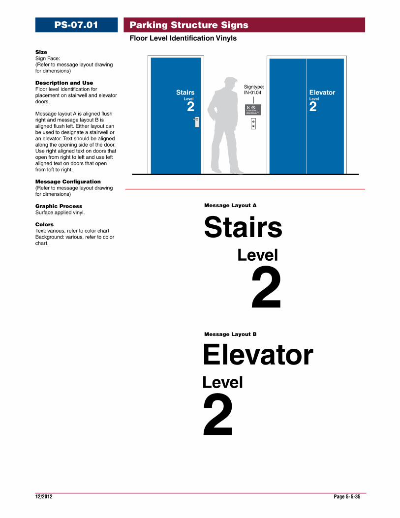
FloorLevelIdentificationVinyls
PS-07.01
Size Sign Face: (Refer to message layout drawing for dimensions)
Description and Use Floor level identification for placement on stairwell and elevator doors.
Message layout A is aligned flush right and message layout B is aligned flush left. Either layout can be used to designate a stairwell or an elevator. Text should be aligned along the opening side of the door. Use right aligned text on doors that open from right to left and use left aligned text on doors that open from left to right.
Message Configuration (Refer to message layout drawing for dimensions)
Graphic Process Surface applied vinyl.
Colors Text: various, refer to color chart Background: various, refer to color chart.
StairsLevel
2ElevatorLevel
2
IN CASE OF FIRE, USE STAIRS. DO NOT USE ELEVATORS.
StairsLevel
2
Signtype:IN-01.04
Message Layout A
Message Layout B
ElevatorLevel
2
Parking Structure Signs
12/2012 Page 5-5-36
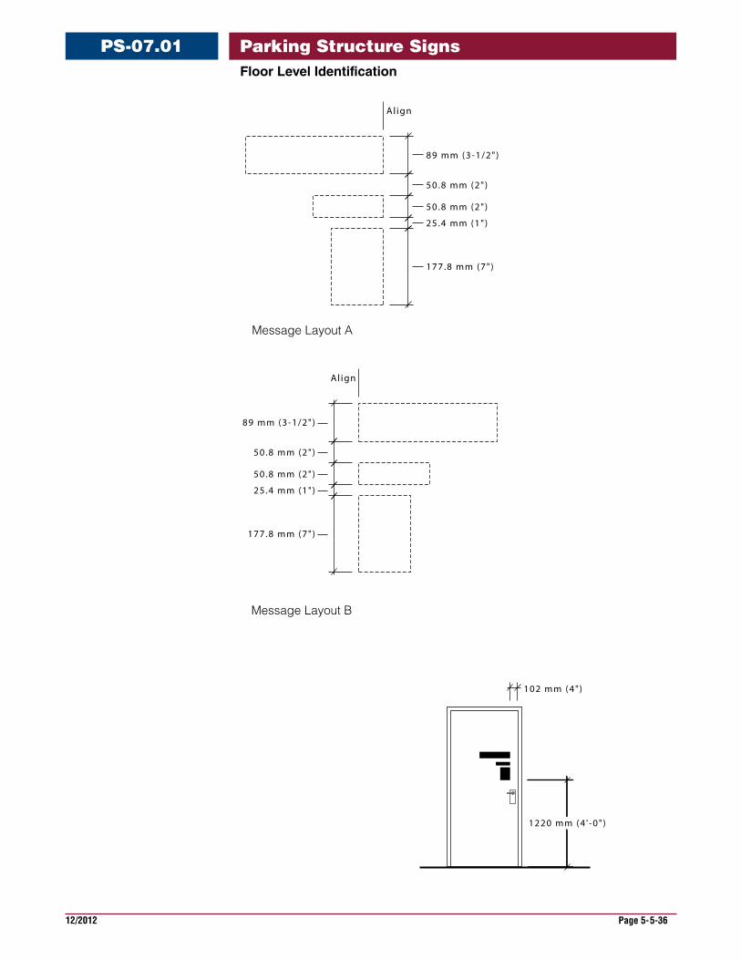
FloorLevelIdentification
PS-07.01
Al ign
89 mm (3-1/2")
50.8 mm (2")
50.8 mm (2")
25.4 mm (1")
177.8 mm (7")
89 mm (3-1/2")
50.8 mm (2")
50.8 mm (2")
25.4 mm (1")
177.8 mm (7")
Al ign
Message Layout B
102 mm (4")
1220 mm (4 ' -0" )
Message Layout A
Parking Structure Signs
12/2012 Page 5-5-37
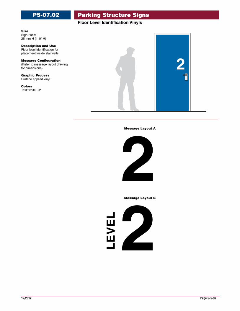
FloorLevelIdentificationVinyls
PS-07.02
2LEVEL2
2
Message Layout A
Message Layout B
Size Sign Face: 25 mm H (1' 0" H)
Description and Use Floor level identification for placement inside stairwells.
Message Configuration (Refer to message layout drawing for dimensions)
Graphic Process Surface applied vinyl.
Colors Text: white, T2
Parking Structure Signs
12/2012 Page 5-5-38
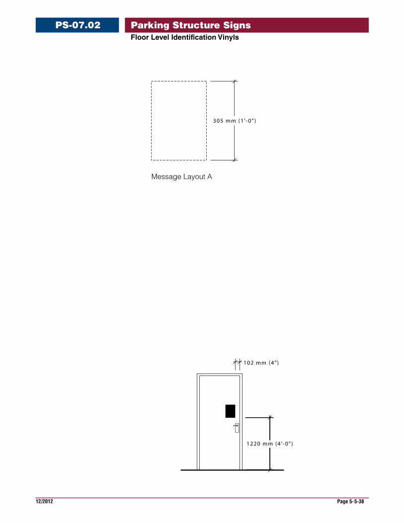
FloorLevelIdentificationVinyls
PS-07.02
305 mm (1 ' -0" )
102 mm (4")
1220 mm (4 ' -0" )
Message Layout A
Parking Structure Signs
12/2012 Page 5-5-39
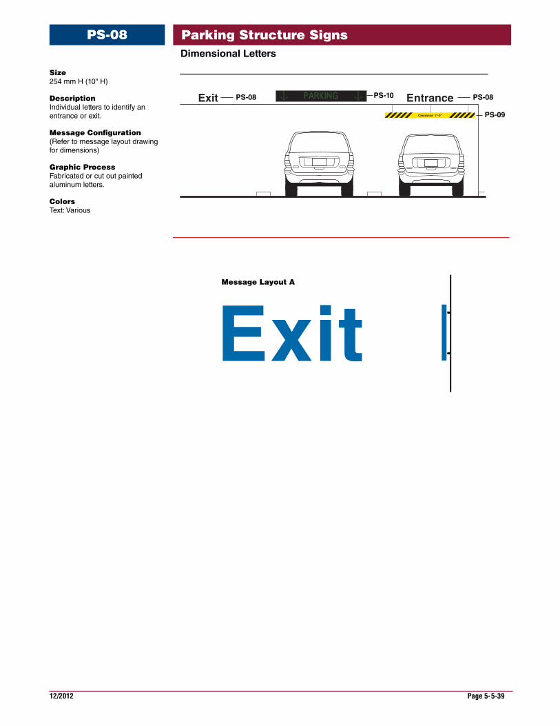
DimensionalLetters
PS-08
Size 254 mm H (10" H)
Description Individual letters to identify an entrance or exit.
Message Configuration (Refer to message layout drawing for dimensions)
Graphic Process Fabricated or cut out painted aluminum letters.
Colors Text: Various
Exit
PS-10
PS-09
PS-08PS-08
Clearance 7'-0"
EntranceExit
Message Layout A
Parking Structure Signs
12/2012 Page 5-5-40
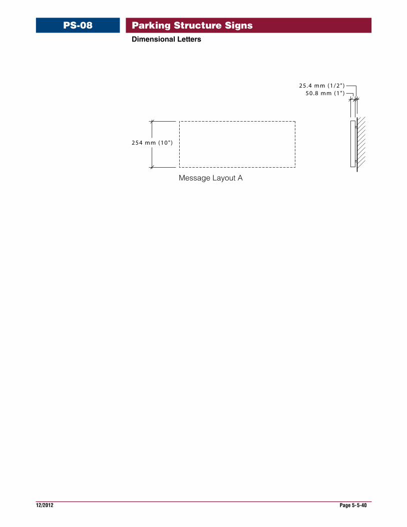
DimensionalLetters
PS-08
254 mm (10")
50.8 mm (1")25.4 mm (1/2")
Message Layout A
Parking Structure Signs
12/2012 Page 5-5-41
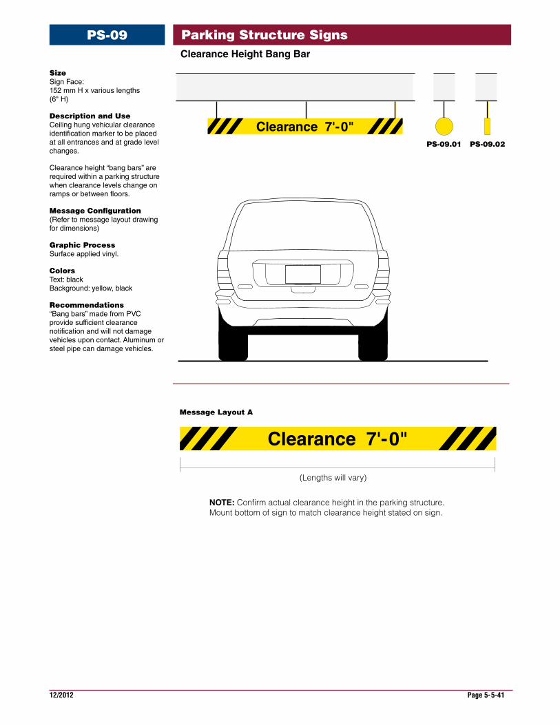
ClearanceHeightBangBar
PS-09
Size Sign Face: 152 mm H x various lengths (6" H)
Description and Use Ceiling hung vehicular clearance identification marker to be placed at all entrances and at grade level changes.
Clearance height “bang bars” are required within a parking structure when clearance levels change on ramps or between floors.
Message Configuration (Refer to message layout drawing for dimensions)
Graphic Process Surface applied vinyl.
Colors Text: black Background: yellow, black
Recommendations “Bang bars” made from PVC provide sufficient clearance notification and will not damage vehicles upon contact. Aluminum or steel pipe can damage vehicles.
Clearance 7'-0"
Clearance 7'-0"
(Lengths will vary)
PS-09.01 PS-09.02
Message Layout A
NOTE: Confirm actual clearance height in the parking structure. Mount bottom of sign to match clearance height stated on sign.
Parking Structure Signs
12/2012 Page 5-5-42
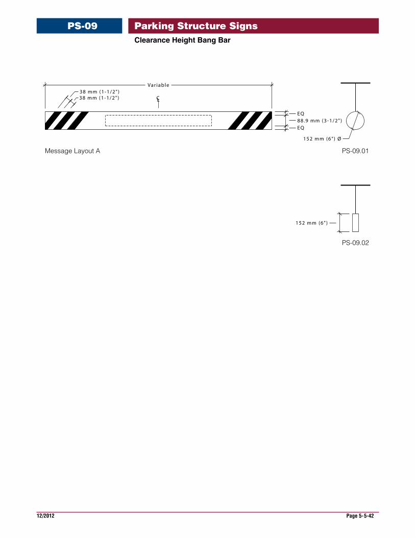
ClearanceHeightBangBar
PS-09
CL38 mm (1-1/2")38 mm (1-1/2")
Var iable
EQ88.9 mm (3-1/2")EQ
152 mm (6") Ø
152 mm (6")
Message Layout A PS-09.01
PS-09.02
Parking Structure Signs
12/2012 Page 5-5-43
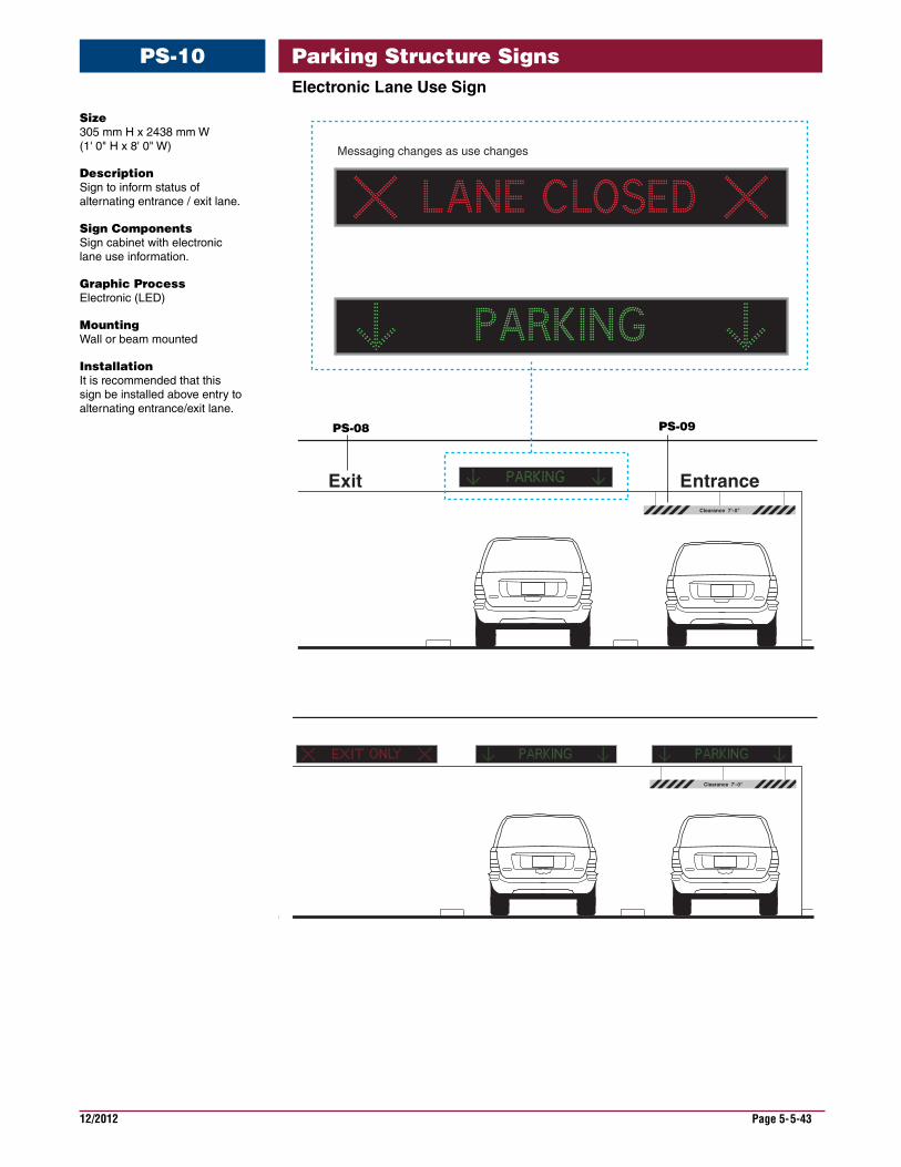
ElectronicLaneUseSign
PS-10
Size 305 mm H x 2438 mm W (1' 0" H x 8' 0" W)
Description Sign to inform status of alternating entrance / exit lane.
Sign Components Sign cabinet with electronic lane use information.
Graphic Process Electronic (LED)
Mounting Wall or beam mounted
Installation It is recommended that this sign be installed above entry to alternating entrance/exit lane.
Clearance 7'-0"
EntranceExit
Messaging changes as use changes
Clearance 7'-0"
PS-09PS-08
Parking Structure Signs
12/2012 Page 5-5-44
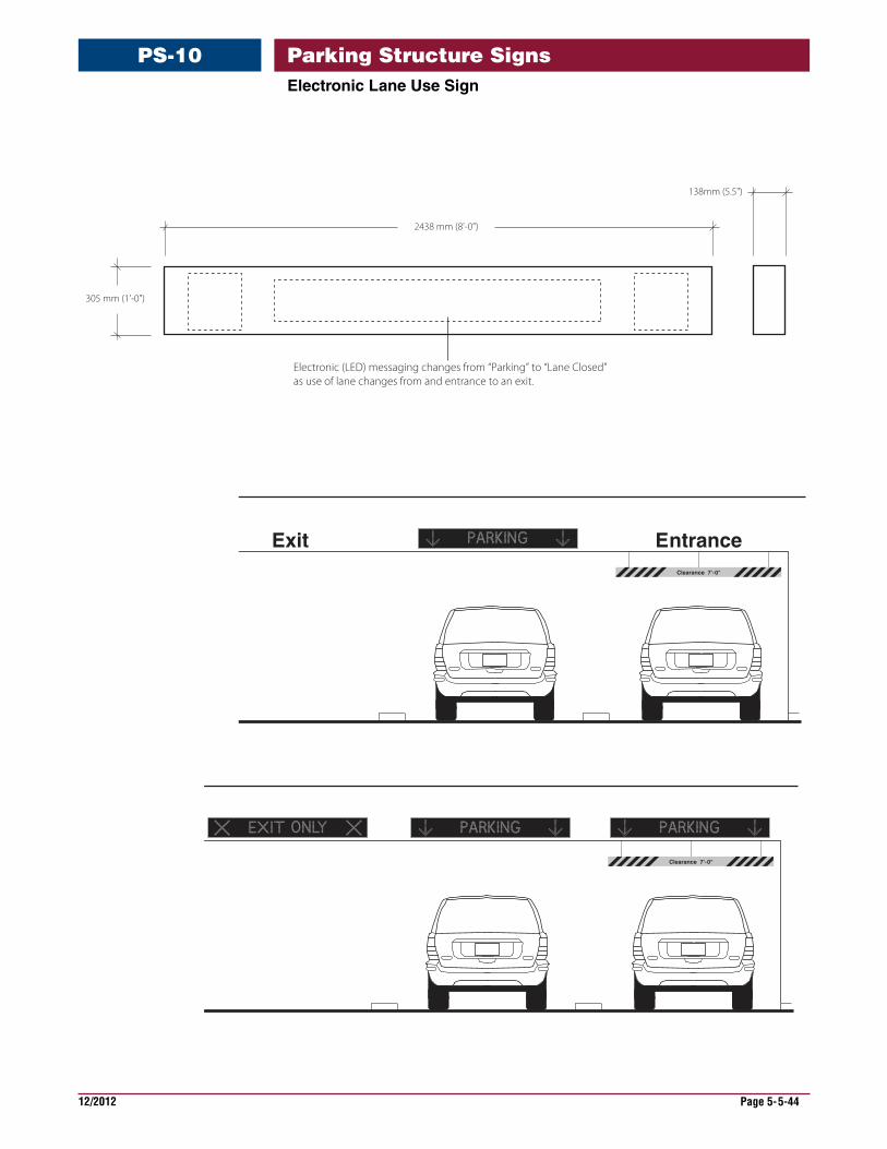
ElectronicLaneUseSign
PS-10
-6”Clearance 7'-0"
EntranceExit
Electronic (LED) messaging changes from “Parking” to “Lane Closed”as use of lane changes from and entrance to an exit.
2438 mm (8'-0")
138mm (5.5")
305 mm (1'-0")
Clearance 7'-0"
Parking Structure Signs
12/2012 Page 5-5-45
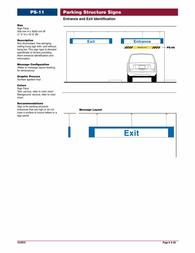
EntranceandExitIdentification
PS-11
Size Sign Face: 559 mm H x 3050 mm W (1' 3" H x 10' 0" W)
Description Non-illuminated, free swinging ceiling hung sign with, and without, bang bar. This sign type is directed specifically to drivers providing them entrance identification and information.
Message Configuration (Refer to message layout drawing for dimensions)
Graphic Process Surface applied vinyl.
Colors Sign Face: Text: various, refer to color chart Background: various, refer to color chart.
Recommendations Sign is for parking structure entrances that are high or do not have a surface to mount letters or a sign panel
Clearance 8’-0”
EntranceExit
Exit
Message Layout
PS-09
Parking Structure Signs
12/2012 Page 5-5-46
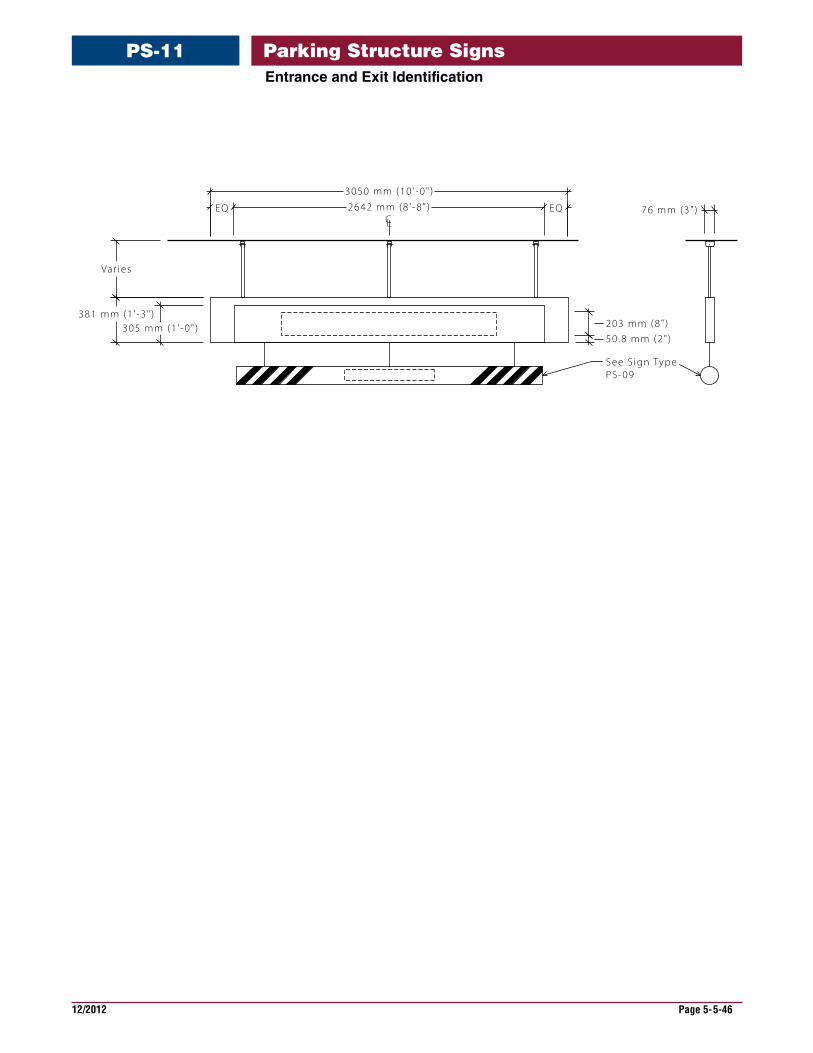
EQ 2642 mm (8 ' -8" ) EQ
3050 mm (10 ' -0" )
CL
305 mm (1 ' -0" )381 mm (1 ' -3" )
203 mm (8" )
50 .8 mm (2" )
76 mm (3" )
See S ign TypePS-09
Var ies
EntranceandExitIdentification
PS-11 Parking Structure Signs
12/2012 Page 5-5-47
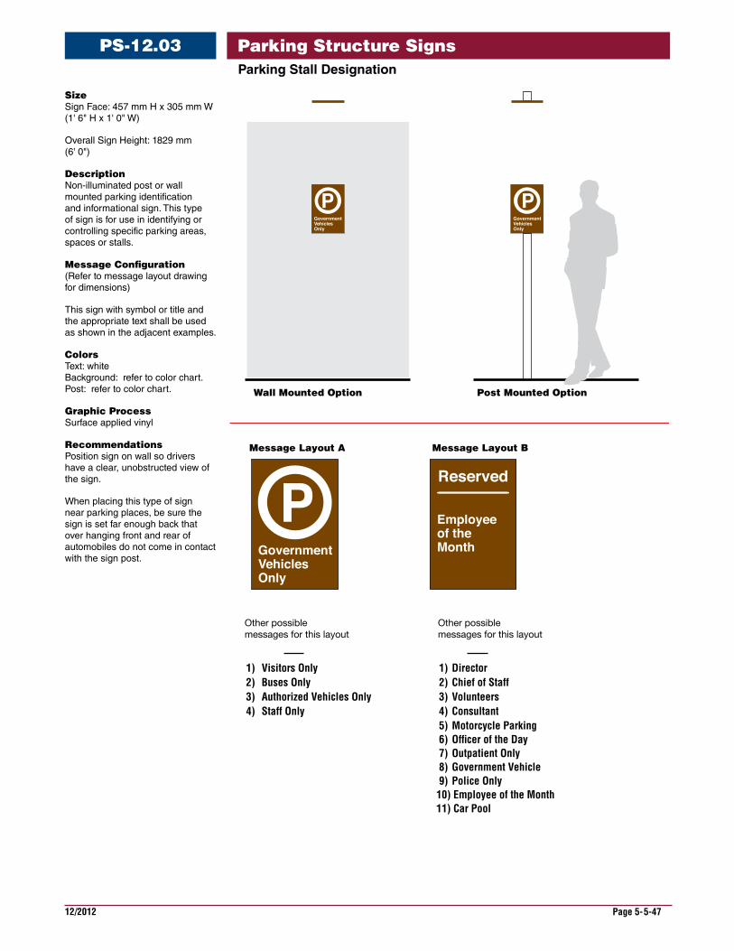
ParkingStallDesignation
PS-12.03
Size Sign Face: 457 mm H x 305 mm W (1' 6" H x 1' 0" W)
Overall Sign Height: 1829 mm (6' 0")
Description Non-illuminated post or wall mounted parking identification and informational sign. This type of sign is for use in identifying or controlling specific parking areas, spaces or stalls.
Message Configuration (Refer to message layout drawing for dimensions)
This sign with symbol or title and the appropriate text shall be used as shown in the adjacent examples.
Colors Text: white Background: refer to color chart. Post: refer to color chart.
Graphic Process Surface applied vinyl
Recommendations Position sign on wall so drivers have a clear, unobstructed view of the sign.
When placing this type of sign near parking places, be sure the sign is set far enough back that over hanging front and rear of automobiles do not come in contact with the sign post.
1) Visitors Only2) Buses Only3) Authorized Vehicles Only4) Staff Only
1) Director 2) Chief of Staff 3) Volunteers 4) Consultant 5) Motorcycle Parking 6) Of�cer of the Day 7) Outpatient Only 8) Government Vehicle 9) Police Only10) Employee of the Month11) Car Pool
Message Layout A
Wall Mounted Option Post Mounted Option
Message Layout B
Other possible messages for this layout
Other possible messages for this layout
Parking Structure Signs
12/2012 Page 5-5-48
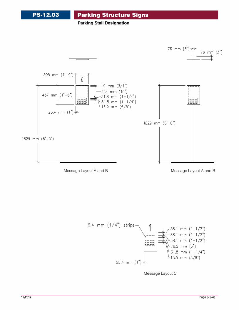
ParkingStallDesignation
PS-12.03
Message Layout A and B Message Layout A and B
Message Layout C
Parking Structure Signs
12/2012 Page 5-5-49
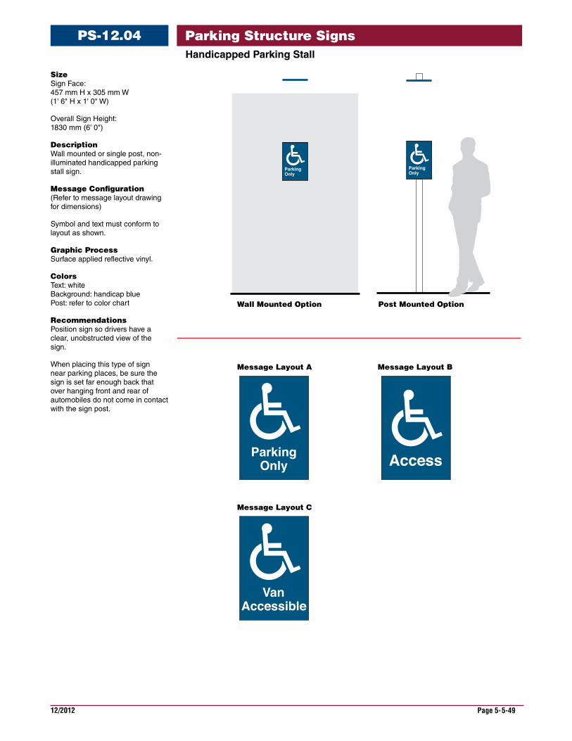
HandicappedParkingStall
PS-12.04
Size Sign Face: 457 mm H x 305 mm W (1' 6" H x 1' 0" W)
Overall Sign Height: 1830 mm (6' 0")
Description Wall mounted or single post, non-illuminated handicapped parking stall sign.
Message Configuration (Refer to message layout drawing for dimensions)
Symbol and text must conform to layout as shown.
Graphic Process Surface applied reflective vinyl.
Colors Text: white Background: handicap blue Post: refer to color chart
Recommendations Position sign so drivers have a clear, unobstructed view of the sign.
When placing this type of sign near parking places, be sure the sign is set far enough back that over hanging front and rear of automobiles do not come in contact with the sign post.
Wall Mounted Option
Message Layout A
Message Layout C
Message Layout B
Post Mounted Option
Parking Structure Signs
12/2012 Page 5-5-50
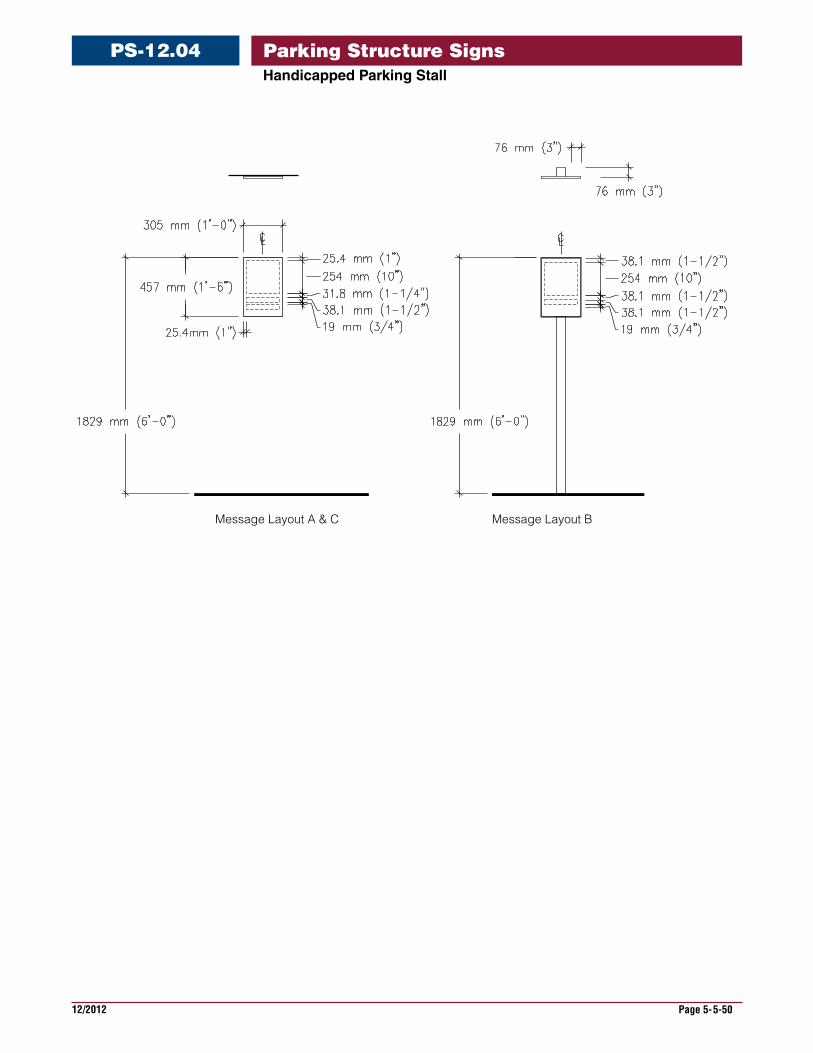
HandicappedParkingStall
PS-12.04
Message Layout A & C Message Layout B
Parking Structure Signs
12/2012 Page 5-5-51
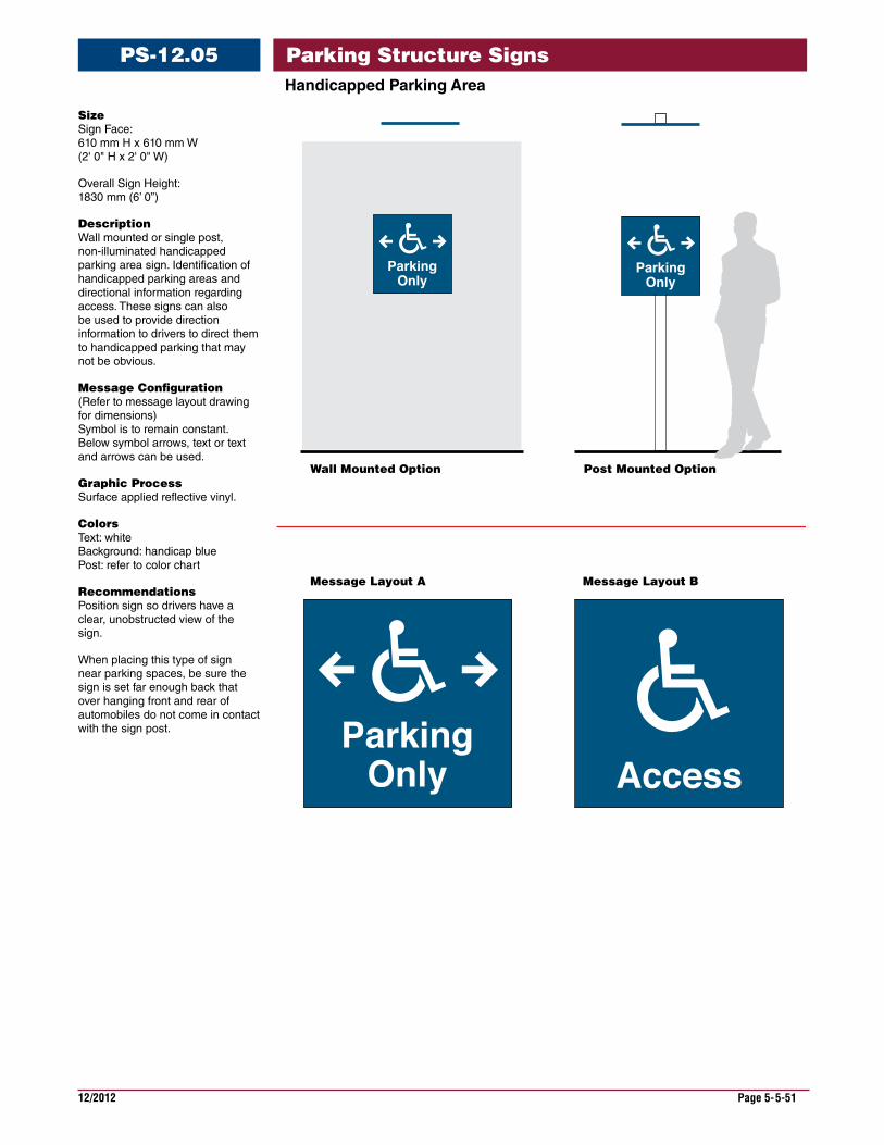
HandicappedParkingArea
PS-12.05
Size Sign Face: 610 mm H x 610 mm W (2' 0" H x 2' 0" W)
Overall Sign Height: 1830 mm (6’ 0”)
Description Wall mounted or single post, non-illuminated handicapped parking area sign. Identification of handicapped parking areas and directional information regarding access. These signs can also be used to provide direction information to drivers to direct them to handicapped parking that may not be obvious.
Message Configuration (Refer to message layout drawing for dimensions) Symbol is to remain constant. Below symbol arrows, text or text and arrows can be used.
Graphic Process Surface applied reflective vinyl.
Colors Text: white Background: handicap blue Post: refer to color chart
Recommendations Position sign so drivers have a clear, unobstructed view of the sign.
When placing this type of sign near parking spaces, be sure the sign is set far enough back that over hanging front and rear of automobiles do not come in contact with the sign post.
Wall Mounted Option
Message Layout A Message Layout B
Post Mounted Option
Parking Structure Signs
12/2012 Page 5-5-52
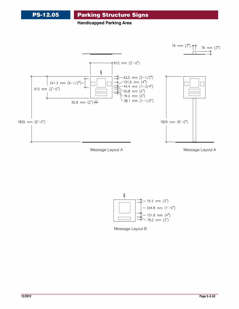
HandicappedParkingArea
PS-12.05
Message Layout A
Message Layout B
Message Layout A
Parking Structure Signs
12/2012 Page 5-5-53
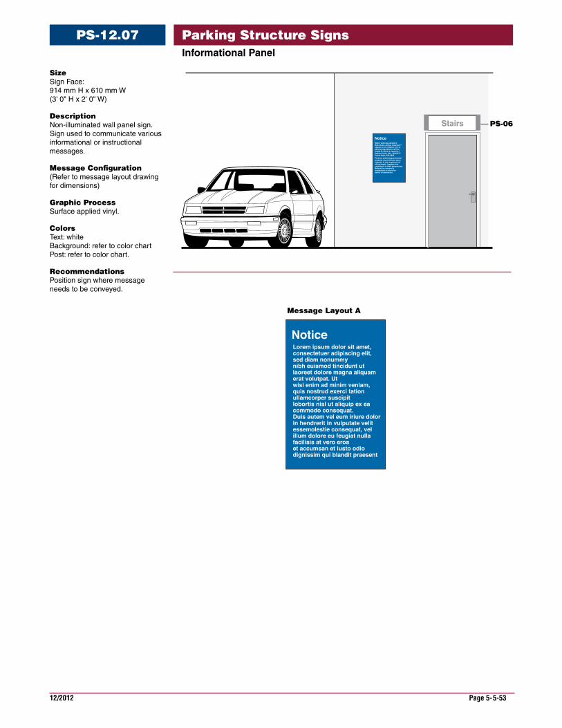
InformationalPanel
PS-12.07
Size Sign Face: 914 mm H x 610 mm W (3' 0" H x 2' 0" W)
Description Non-illuminated wall panel sign. Sign used to communicate various informational or instructional messages.
Message Configuration (Refer to message layout drawing for dimensions)
Graphic Process Surface applied vinyl.
Colors Text: white Background: refer to color chart Post: refer to color chart.
Recommendations Position sign where message needs to be conveyed.
Stairs
Message Layout A
PS-06
Parking Structure Signs
12/2012 Page 5-5-54
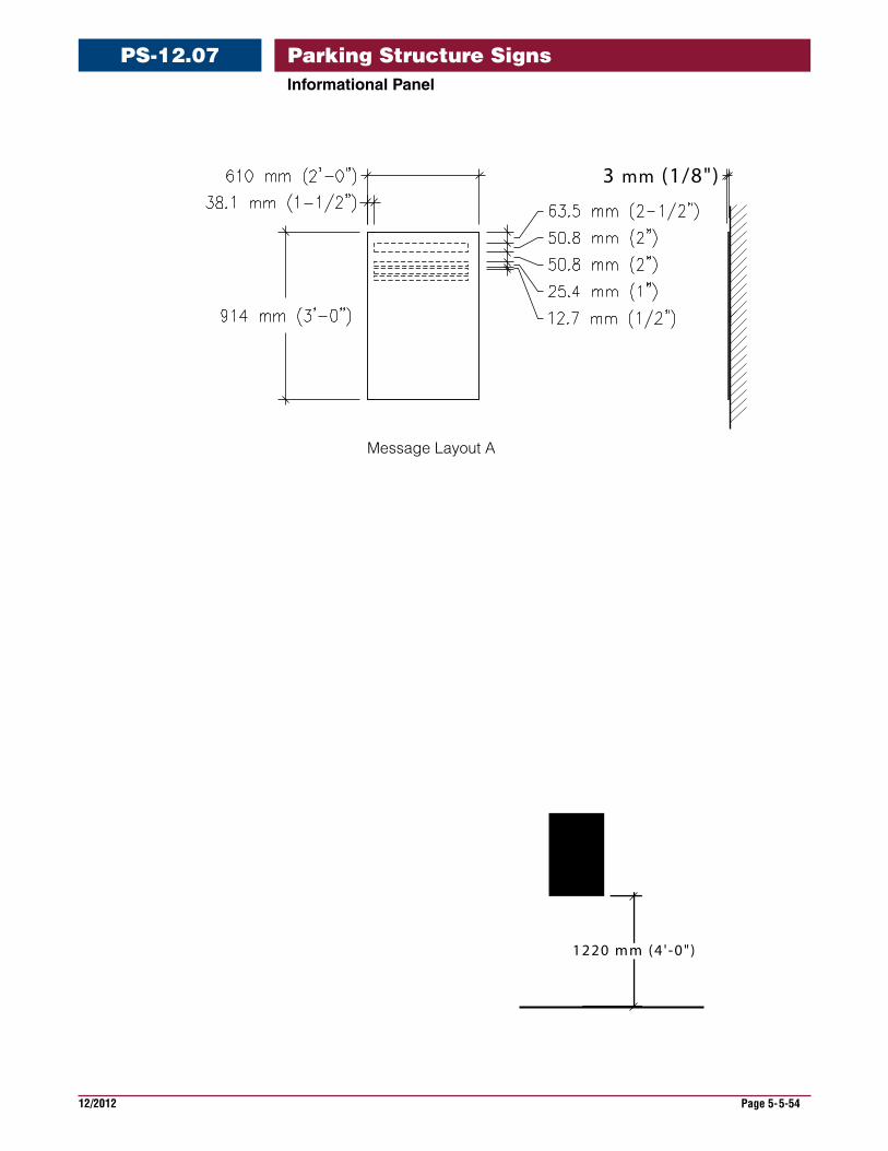
InformationalPanel
PS-12.07
3 mm (1/8")
1220 mm (4 ' -0" )
Message Layout A
Parking Structure Signs
12/2012 Page 5-5-55
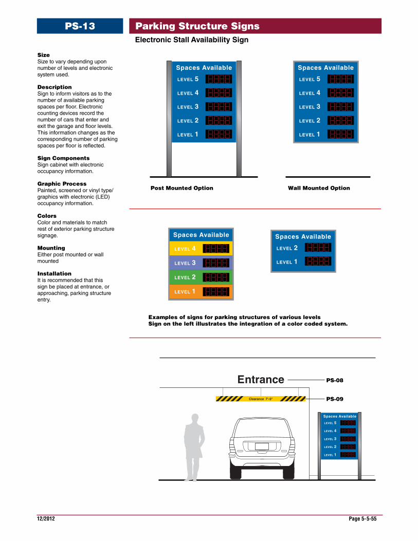
ElectronicStallAvailabilitySign
PS-13
Size Size to vary depending upon number of levels and electronic system used.
Description Sign to inform visitors as to the number of available parking spaces per floor. Electronic counting devices record the number of cars that enter and exit the garage and floor levels. This information changes as the corresponding number of parking spaces per floor is reflected.
Sign Components Sign cabinet with electronic occupancy information.
Graphic Process Painted, screened or vinyl type/graphics with electronic (LED) occupancy information.
Colors Color and materials to match rest of exterior parking structure signage.
Mounting Either post mounted or wall mounted
Installation It is recommended that this sign be placed at entrance, or approaching, parking structure entry.
Clearance 7'-0"
Entrance
Post Mounted Option
Examples of signs for parking structures of various levelsSign on the left illustrates the integration of a color coded system.
Wall Mounted Option
Spaces Available
LEVEL 4
LEVEL 3
LEVEL 2
LEVEL 5
LEVEL 1
Spaces Available
LEVEL 4
LEVEL 3
LEVEL 2
LEVEL 5
LEVEL 1
Spaces Available
LEVEL 1
LEVEL 2
Spaces Available
LEVEL 3
LEVEL 2
LEVEL 1
LEVEL 4
Spaces Available
LEVEL 4
LEVEL 3
LEVEL 2
LEVEL 5
LEVEL 1
PS-08
PS-09
Parking Structure Signs
12/2012 Page 5-5-56
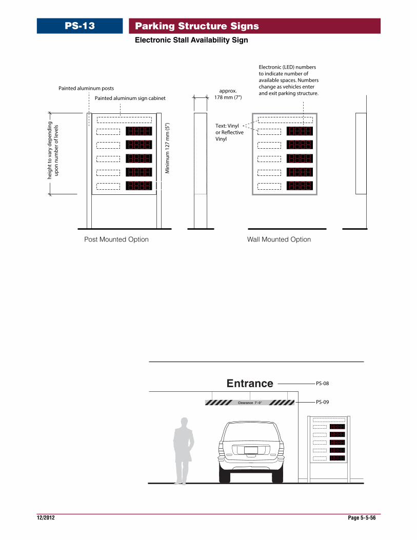
ElectronicStallAvailabilitySign
PS-13
-6”Clearance 7’-0”
Entrance
Post Mounted Option Wall Mounted Option
Electronic (LED) numbersto indicate number of available spaces. Numbers change as vehicles enterand exit parking structure.
heig
ht to
var
y de
pend
ing
upon
num
ber o
f lev
els
Min
imum
127
mm
(5")
approx.178 mm (7")
Painted aluminum posts
Painted aluminum sign cabinet
Text: Vinylor Re�ectiveVinyl
PS-08
PS-09
Parking Structure Signs
12/2012 Page 5-5-57
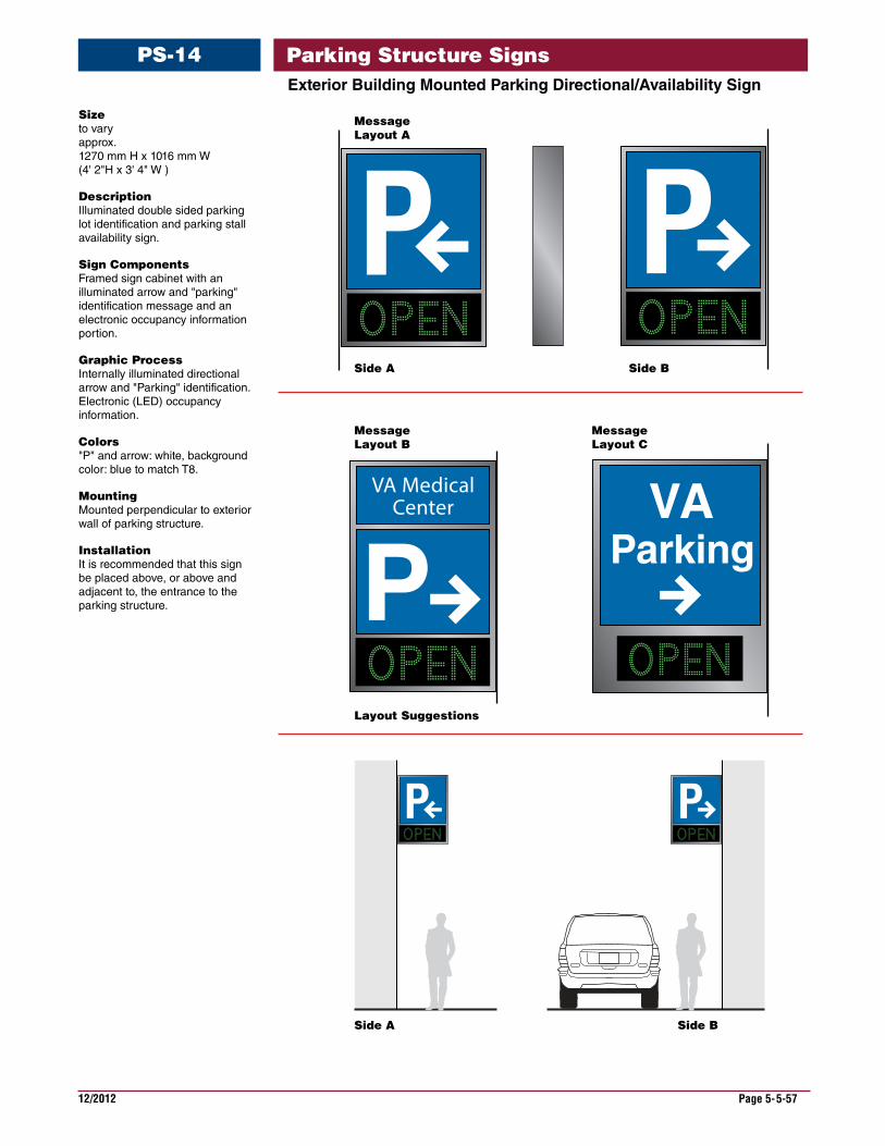
ExteriorBuildingMountedParkingDirectional/AvailabilitySign
PS-14
Size to vary approx. 1270 mm H x 1016 mm W (4' 2"H x 3' 4" W )
Description Illuminated double sided parking lot identification and parking stall availability sign.
Sign Components Framed sign cabinet with an illuminated arrow and "parking" identification message and an electronic occupancy information portion.
Graphic Process Internally illuminated directional arrow and "Parking" identification. Electronic (LED) occupancy information.
Colors "P" and arrow: white, background color: blue to match T8.
Mounting Mounted perpendicular to exterior wall of parking structure.
Installation It is recommended that this sign be placed above, or above and adjacent to, the entrance to the parking structure.
Side A
Layout Suggestions
MessageLayout A
MessageLayout B
MessageLayout C
Side B
Side A Side B
PP
P P
PVA Medical
Center
ParkingVA
Parking Structure Signs
12/2012 Page 5-5-58
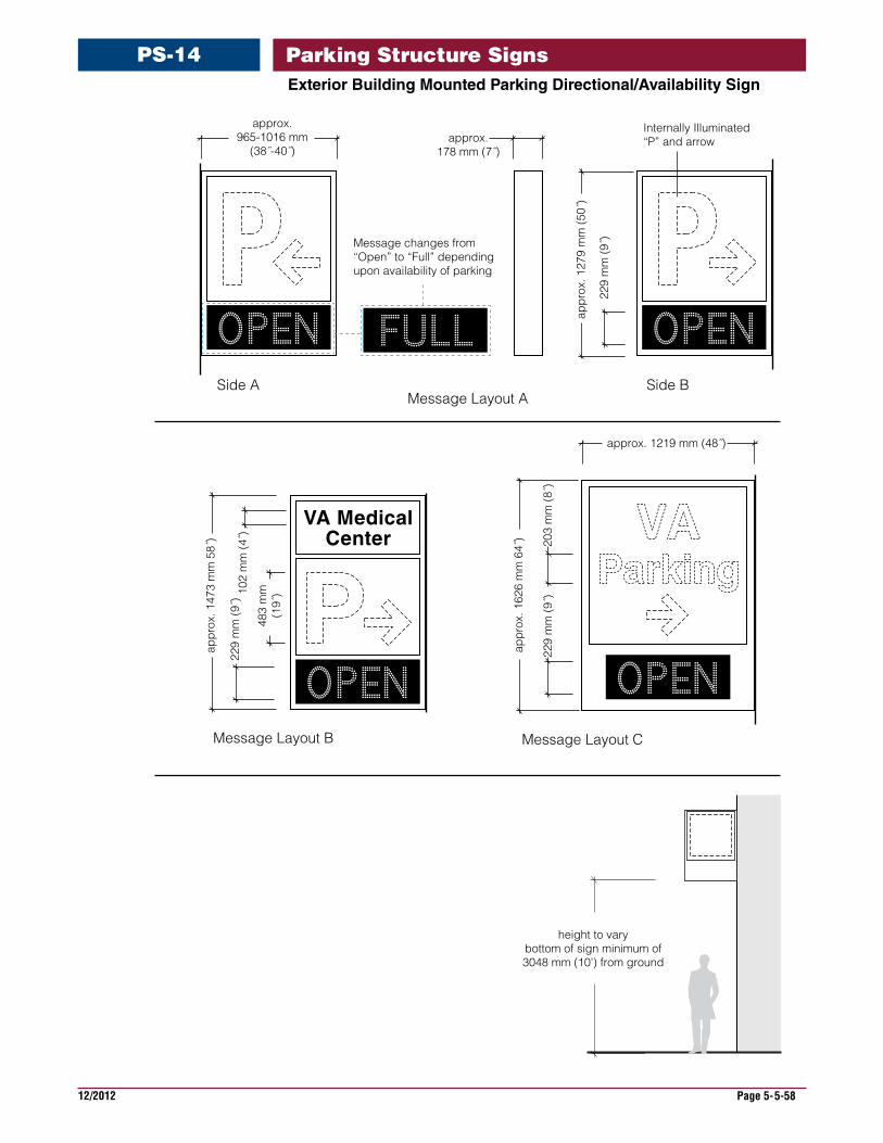
ExteriorBuildingMountedParkingDirectional/AvailabilitySign
PS-14
appr
ox. 1
279
mm
(50˝
)
229
mm
(9˝)
approx.965-1016 mm
(38˝-40˝)approx.
178 mm (7˝)
Message changes from “Open” to “Full” depending upon availability of parking
Internally Illuminated“P” and arrow
height to varybottom of sign minimum of3048 mm (10') from ground
229
mm
(9˝)
appr
ox. 1
626
mm
64˝
)
approx. 1219 mm (48˝)
203
mm
(8˝)
Message Layout C
Side A Side B
appr
ox. 1
473
mm
58˝
)
229
mm
(9˝)
VA MedicalCenter
483
mm
(19˝
)102
mm
(4˝)
Message Layout B
Message Layout A
Parking Structure Signs
12/2012 Page 5-5-59
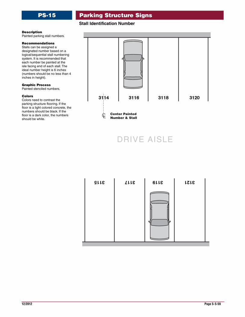
StallIdentificationNumber
Description Painted parking stall numbers.
Recommendations Stalls can be assigned a designated number based on a logical/sequential stall numbering system. It is recommended that each number be painted at the isle facing end of each stall. The ideal number height is 6 inches (numbers should be no less than 4 inches in height).
Graphic Process Painted stenciled numbers.
Colors Colors need to contrast the parking structure flooring. If the floor is a light colored concrete, the numbers should be black. If the floor is a dark color, the numbers should be white.
CLCenter PaintedNumber & Stall
DRIVE AISLE
PS-15 Parking Structure Signs
12/2012 Page 5-5-60
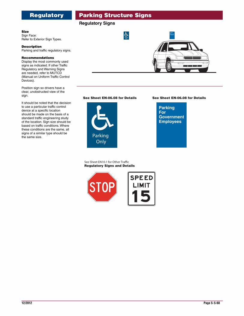
RegulatorySigns
Size Sign Face: Refer to Exterior Sign Types.
Description Parking and traffic regulatory signs.
Recommendations Display the most commonly used signs as indicated. If other Traffic Regulatory and Warning Signs are needed, refer to MUTCD (Manual on Uniform Traffic Control Devices).
Position sign so drivers have a clear, unobstructed view of the sign.
It should be noted that the decision to use a particular traffic control device at a specific location should be made on the basis of a standard traffic engineering study of the location. Sign size should be based on traffic conditions. Where these conditions are the same, all signs of a similar type should be the same size. Parking
Only
See Sheet EN10.1 for Other Tra�c Regulatory Signs and Details
See Sheet EN-06.08 for Details See Sheet EN-06.08 for Details
ParkingForGovernmentEmployees
Parking Structure SignsRegulatory
12/2012 Page 5-5-61
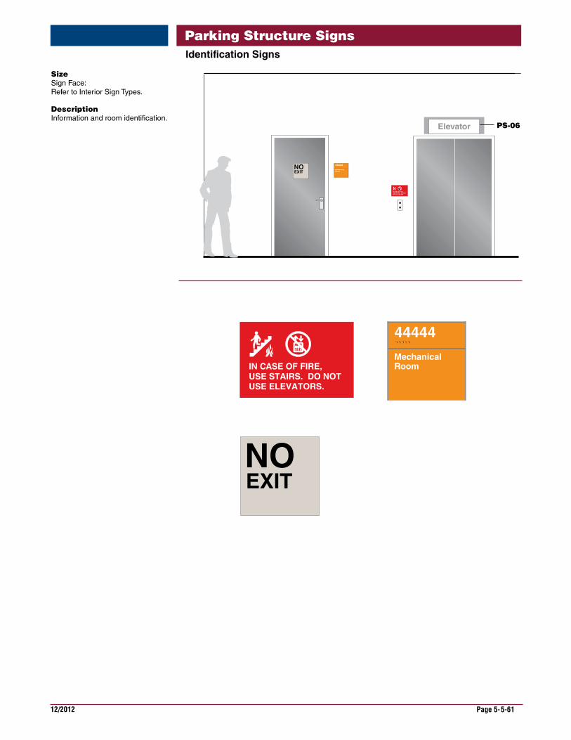
IdentificationSigns
Size Sign Face: Refer to Interior Sign Types.
Description Information and room identification.
IN CASE OF FIRE, USE STAIRS. DO NOT USE ELEVATORS.
PS-06Elevator
NOEXIT
44444
MechanicalRoom
NO EXIT
Parking Structure Signs
12/2012 Page 5-5-62
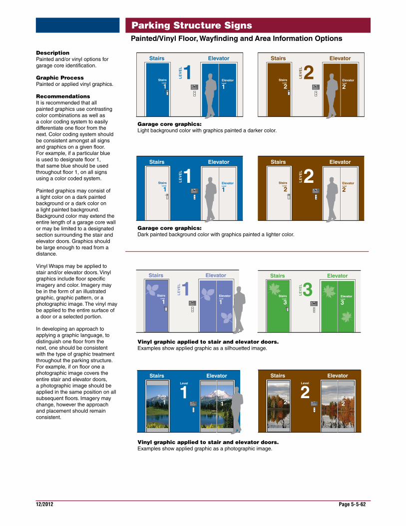
Painted/VinylFloor,WayfindingandAreaInformationOptions
Description Painted and/or vinyl options for garage core identification.
Graphic Process Painted or applied vinyl graphics.
Recommendations It is recommended that all painted graphics use contrasting color combinations as well as a color coding system to easily differentiate one floor from the next. Color coding system should be consistent amongst all signs and graphics on a given floor. For example, if a particular blue is used to designate floor 1, that same blue should be used throughout floor 1, on all signs using a color coded system.
Painted graphics may consist of a light color on a dark painted background or a dark color on a light painted background. Background color may extend the entire length of a garage core wall or may be limited to a designated section surrounding the stair and elevator doors. Graphics should be large enough to read from a distance.
Vinyl Wraps may be applied to stair and/or elevator doors. Vinyl graphics include floor specific imagery and color. Imagery may be in the form of an illustrated graphic, graphic pattern, or a photographic image. The vinyl may be applied to the entire surface of a door or a selected portion.
In developing an approach to applying a graphic language, to distinguish one floor from the next, one should be consistent with the type of graphic treatment throughout the parking structure. For example, if on floor one a photographic image covers the entire stair and elevator doors, a photographic image should be applied in the same position on all subsequent floors. Imagery may change, however the approach and placement should remain consistent.
IN CASE OF FIRE, USE STAIRS. DO NOT USE ELEVATORS.
1ElevatorStairs
LE
VE
L
IN CASE OF FIRE, USE STAIRS. DO NOT USE ELEVATORS.
2ElevatorStairs
LE
VE
L
IN CASE OF FIRE, USE STAIRS. DO NOT USE ELEVATORS.
1ElevatorStairs
LE
VE
L
IN CASE OF FIRE, USE STAIRS. DO NOT USE ELEVATORS.
2ElevatorStairs
LE
VE
L
StairsLevel
2ElevatorLevel
2Stairs
Level
1ElevatorLevel
1
StairsLevel
2ElevatorLevel
2Stairs
Level
1ElevatorLevel
1
IN CASE OF FIRE, USE STAIRS. DO NOT USE ELEVATORS.
1ElevatorStairs
Level
IN CASE OF FIRE, USE STAIRS. DO NOT USE ELEVATORS.
1ElevatorStairs
LE
VE
L
ElevatorLevel
1Stairs
Level
1
ElevatorLevel
1Stairs
Level
1 IN CASE OF FIRE, USE STAIRS. DO NOT USE ELEVATORS.
2ElevatorStairs
Level
IN CASE OF FIRE, USE STAIRS. DO NOT USE ELEVATORS.
3ElevatorStairs
LE
VE
LElevatorLevel
3Stairs
Level
3
ElevatorLevel
2Stairs
Level
2
Garage core graphics: Light background color with graphics painted a darker color.
Garage core graphics: Dark painted background color with graphics painted a lighter color.
Vinyl graphic applied to stair and elevator doors. Examples show applied graphic as a silhouetted image.
Vinyl graphic applied to stair and elevator doors. Examples show applied graphic as a photographic image.
Parking Structure Signs
12/2012 Page 5-5-63
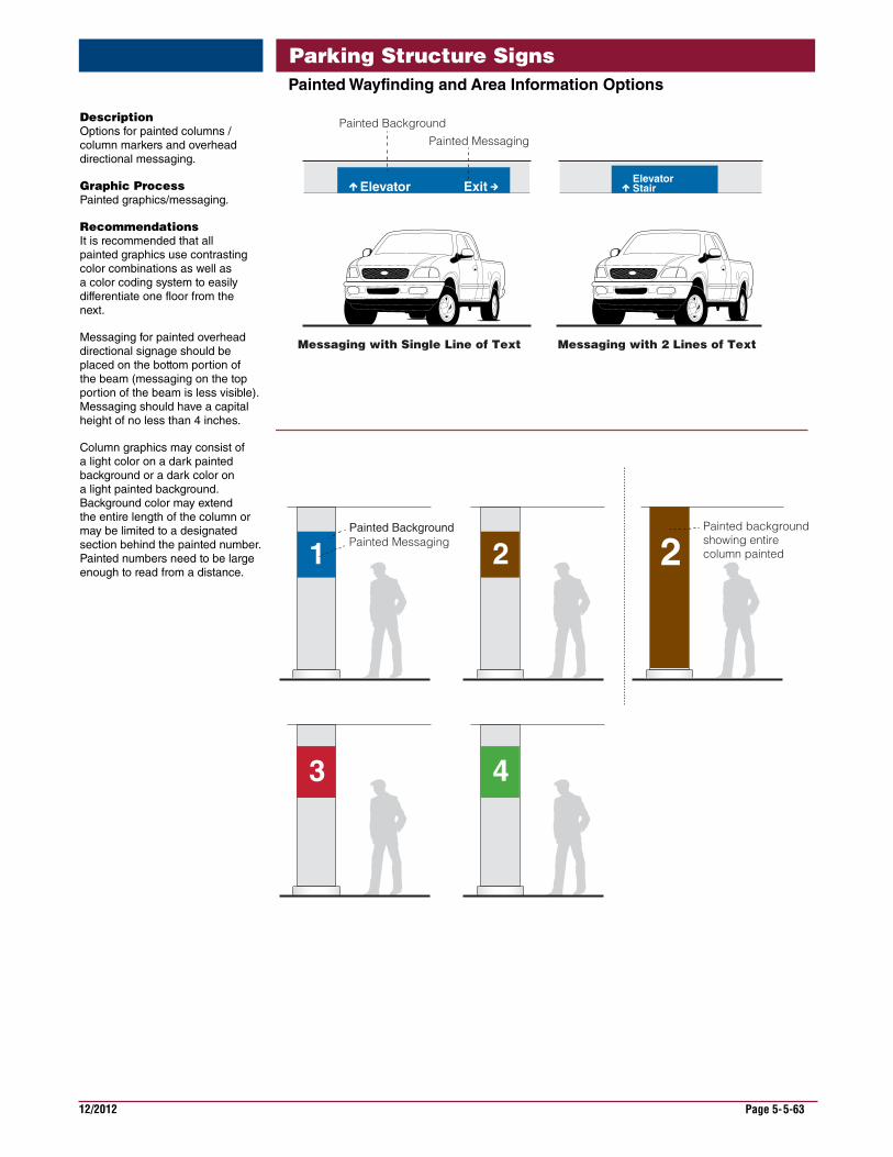
PaintedWayfindingandAreaInformationOptions
Description Options for painted columns / column markers and overhead directional messaging.
Graphic Process Painted graphics/messaging.
Recommendations It is recommended that all painted graphics use contrasting color combinations as well as a color coding system to easily differentiate one floor from the next.
Messaging for painted overhead directional signage should be placed on the bottom portion of the beam (messaging on the top portion of the beam is less visible). Messaging should have a capital height of no less than 4 inches.
Column graphics may consist of a light color on a dark painted background or a dark color on a light painted background. Background color may extend the entire length of the column or may be limited to a designated section behind the painted number. Painted numbers need to be large enough to read from a distance.
3
1
4
2 2
StairElevator
Elevator Exit
Painted BackgroundPainted Messaging
Painted Background
Messaging with Single Line of Text Messaging with 2 Lines of Text
Painted Messaging Painted backgroundshowing entire column painted
Parking Structure Signs

This page is intentionally left blank.
12/2012 Page 5-6-1
The specifications for signs are available in the Master Construction Specifications (PG-18-1) area of the VA Technical Information Library, which is available on the VA web site under Office of Construction & Facilities Management.
www.cfm.va.gov/til/
Refer to Signage in the specifications, Division 10, Section 10 14 00.
For more information regarding specifications, contact the Office of Construction & Facilities Management, Facility Standards Service.
The specifications require close coordination, taking into account the existing sign program at a medical center, any sign demolition, sign maintenance and future signing needs.
When preparing the specifications for a project, it will require editing to add and indicate new signs or eliminate signs that are not needed. Also, it will be necessary to adapt the specifications to project requirements required for the specific project in which they are intended.
The sign message schedule is considered a part of the specifications and would comprise a portion of the spec section. The configuration and format of the mes-sage schedule may vary according to individual project requirements. The sign message schedule format is shown in the Need a Sign Program section of the VA Signage Design Guide. It provides the method for identifying each sign location, type and message along with other notations. The sign schedule contains important information that the sign manufacturer and the sign installer will require for manu-facturing and sign installation.
The sign message schedule must be coordinated with a sign location plan drawing showing where signs are to be placed within a building or on the site. Refer to the sign location plan example shown in the NeedaSignProgram section of the VA Signage Design Guide.
For convenience, the sign type drawings can also be included in the specifications as it own section.
Parking Structure SignsSpecification

This page is intentionally left blank.
12/2012 Page 5-7-1
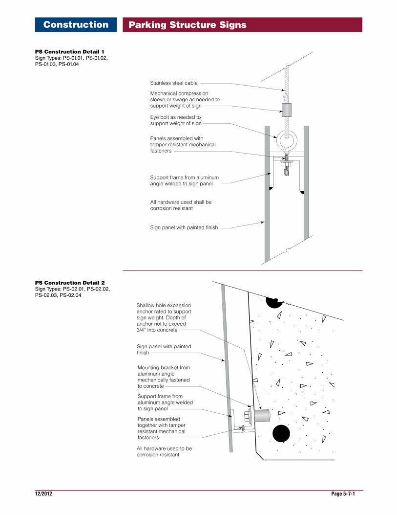
PS Construction Detail 1 Sign Types: PS-01.01, PS-01.02, PS-01.03, PS-01.04
Stainless steel cable
Mechanical compression sleeve or swage as needed to support weight of sign
Sign panel with painted finish
Support frame from aluminum angle welded to sign panel
Panels assembled with tamper resistant mechanical fasteners
All hardware used shall be corrosion resistant
Eye bolt as needed to support weight of sign
Shallow hole expansion anchor rated to support sign weight. Depth of anchor not to exceed 3/4” into concrete
Shallow hole expansion anchor rated to support sign weight. Depth of anchor not to exceed 3/4” into concrete
Concrete joist
Mounting bracket from inter locking angle with set screw attachment to sign panel
Sign
Sign panel with painted finish
Support frame from aluminum angle welded to sign panel
Mounting bracket from aluminum angle mechanically fastened to concrete
Panels assembled together with tamper resistant mechanical fasteners
All hardware used to be corrosion resistant
All hardware used to be corrosion resistant
3/4" Max
PS Construction Detail 2 Sign Types: PS-02.01, PS-02.02, PS-02.03, PS-02.04
Parking Structure SignsConstruction
12/2012 Page 5-7-2
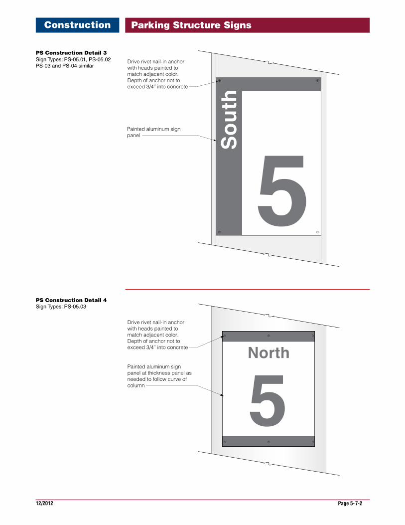
PS Construction Detail 3 Sign Types: PS-05.01, PS-05.02 PS-03 and PS-04 similar
Drive rivet nail-in anchor with heads painted to match adjacent color. Depth of anchor not to exceed 3/4” into concrete
Painted aluminum sign panel at thickness panel as needed to follow curve of column
Drive rivet nail-in anchor with heads painted to match adjacent color. Depth of anchor not to exceed 3/4” into concrete
Painted aluminum sign panel
PS Construction Detail 4 Sign Types: PS-05.03
Parking Structure SignsConstruction
12/2012 Page 5-7-3
CL
CL
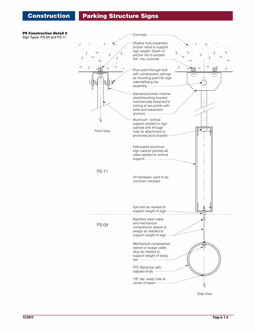
Mechanical compression sleeve or swage cable stop as needed to support weight of bang bar
Shallow hole expansion anchor rated to support sign weight. Depth of anchor not to exceed 3/4” into concrete
Concrete
Eye bolt as needed to support weight of sign
1/8” dia. weep hole at center of beam
PVC Bang bar with capped ends
Stainless steel cable and mechanical compression sleeve or swage as needed to support weight of sign
Fabricated aluminum sign cabinet painted all sides welded to vertical support
Aluminum vertical support welded to sign cabinet with through hole for attachment to anchored pivot bracket
Galvanized steel channel pivot/mounting bracket mechanically fastened to ceiling at two points with bolts and expansion anchors
Pivot point through bolt with compression springs as mounting point for sign cabinet/bang bar assembly
All hardware used to be corrosion resistant
Front View
PS-11
PS-09
Side View
PS Construction Detail 5 Sign Types: PS-09 and PS-11
Parking Structure SignsConstruction

This page is intentionally left blank.
12/2012 Page 5-8-1
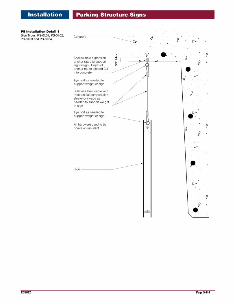
PS Installation Detail 1 Sign Types: PS-01.01, PS-01.02, PS-01.03 and PS-01.04
All hardware used to be corrosion resistant
Shallow hole expansion anchor rated to support sign weight. Depth of anchor not to exceed 3/4” into concrete
Concrete
Eye bolt as needed to support weight of sign
Stainless steel cable with mechanical compression sleeve or swage as needed to support weight of sign
Sign
Eye bolt as needed to support weight of sign
3/4"
Max
Parking Structure SignsInstallation
12/2012 Page 5-8-2
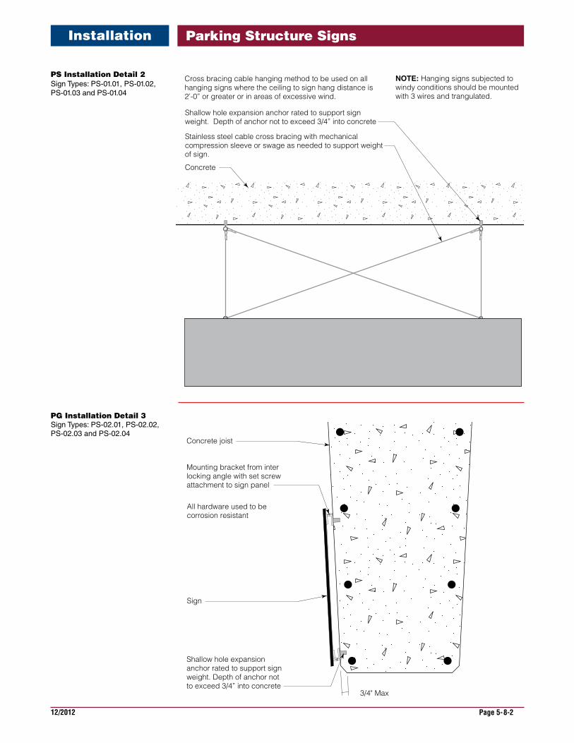
PG Installation Detail 3 Sign Types: PS-02.01, PS-02.02, PS-02.03 and PS-02.04
Shallow hole expansion anchor rated to support sign weight. Depth of anchor not to exceed 3/4” into concrete
Shallow hole expansion anchor rated to support sign weight. Depth of anchor not to exceed 3/4” into concrete
Concrete joist
Mounting bracket from inter locking angle with set screw attachment to sign panel
Sign
Sign panel with painted finish
Support frame from aluminum angle welded to sign panel
Mounting bracket from aluminum angle mechanically fastened to concrete
Panels assembled together with tamper resistant mechanical fasteners
All hardware used to be corrosion resistant
All hardware used to be corrosion resistant
3/4" Max
Stainless steel cable cross bracing with mechanical compression sleeve or swage as needed to support weight of sign.
Cross bracing cable hanging method to be used on all hanging signs where the ceiling to sign hang distance is 2’-0” or greater or in areas of excessive wind.
Shallow hole expansion anchor rated to support sign weight. Depth of anchor not to exceed 3/4” into concrete
Concrete
NOTE: Hanging signs subjected to windy conditions should be mounted with 3 wires and trangulated.
PS Installation Detail 2 Sign Types: PS-01.01, PS-01.02, PS-01.03 and PS-01.04
Parking Structure SignsInstallation
12/2012 Page 5-8-3
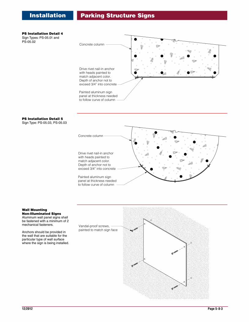
PS Installation Detail 4 Sign Types: PS-05.01 and PS-05.02
PS Installation Detail 5 Sign Type: PS-05.03, PS-05.03
Drive rivet nail-in anchor with heads painted to match adjacent color. Depth of anchor not to exceed 3/4” into concrete
Concrete column
Painted aluminum sign panel at thickness needed to follow curve of column
Drive rivet nail-in anchor with heads painted to match adjacent color. Depth of anchor not to exceed 3/4” into concrete
Concrete column
Painted aluminum sign panel at thickness needed to follow curve of column
Vandal-proof screws, painted to match sign face
Wall Mounting Non-Illuminated Signs Aluminum wall panel signs shall be fastened with a minimum of 2 mechanical fasteners.
Anchors should be provided in the wall that are suitable for the particular type of wall surface where the sign is being installed.
Parking Structure SignsInstallation