ux router manual - wadkin - woodworking machines ux router jig manual.pdf · ux router jig manual...
TRANSCRIPT
UX ROUTER
Jig Manual
INSTRUCTION MANUAL No. 5008 www.w
adkin
.com
info@
wadkin
.com
HEALTH & SAFETY
SAFETY OF WOODWORKING MACHINES
Woodworking machines can be dangerous if improperly used. The wide range of work of which they are capable, requires adequate safeguarding arrangements against possible hazards.
Many injuries to machinists are caused by carelessness or failure to use the gua.r?S provided or to ajust them correctly.
WADKIN PLC supply machinery designed for maximum safety which they believe, as a result of thorough testing, minimizes the risk~. inevitable in their use. It is the user's responsibility to see that the following rules are compiled with to ensure safety at work:
1. The operation of the machine should conform to the requirements of the Woodworking Machines Regulations 1974. All guards should be us~d and ajusted correctly.
2. Only safe methods of working should be adopted as given in the Health & Safety Booklet No. 41, "Safety in the Use of Woodworking Machines", Cobtained from Her Majesty's Stationery Office) and as advised by Wadkin plc.
3. Only personnel trained in .the safe use of a machine should operate it. . ..
4. Before making adjustments or clearing chips, etc. the machines should be stopped and all movements should have ceased.
5. All tools and cutters must be securely fixed and the speed selected must be appropriate for the tooling.
6. It is'not unusual for Routers to operate at noise levels above 90 dBCA) depending on extraction, spindle speed, tool form and type head etc,. We therefore recommend that ear protection is worn by anyone working in close proximity to the machine whilst in use.
SAFETY IS OUR WATCHWORD BUT THE USER MUST COMPLY WITH THE ABOVE RULES IN HIS OWN INTEREST. WE WOULD BE PLEASED TO ADVISE ON THE SAFE USE OF OUR PRODUCTS.
www.wad
kin.co
m
info@
wadkin
.com
. ~ ..
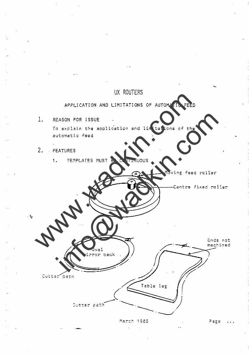
UX ROUTERS
APPLICATION AND LIMITATIONS OF AUTOMATIC FEED
1. REASON FOR ISSUE
To explain the appli;ation and limitations of th~
automatic feed
2. FEATURES
1. TEMPLATES MUST BE CONTINUOUS
.....
__ ----~~.-------Moving feed roller
~~~~----~entre iixed roller
cnds not
Oval mirrer back
_.. /~~. :=~::::~ LUttar patn
Table leg
C~t::ar
Mar=:; 1920
www.wad
kin.co
m
info@
wadkin
.com
.J
/ . ~ ..
~!IJ I 26
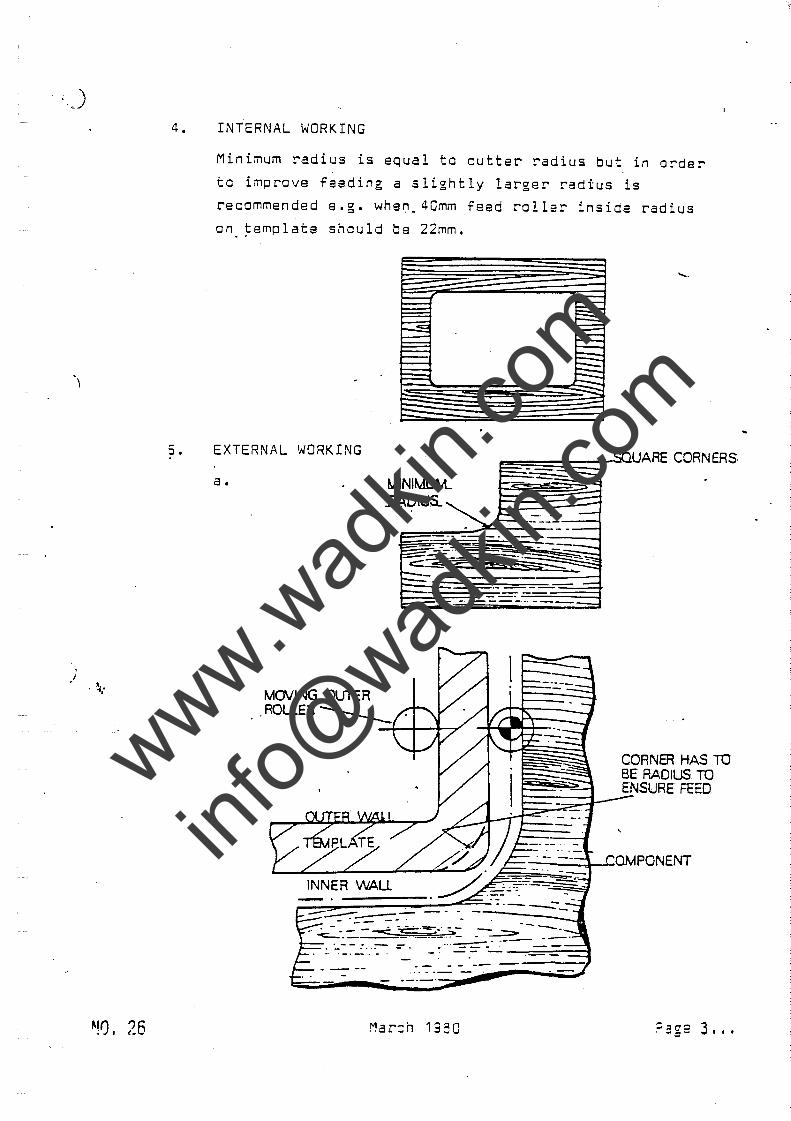
4. INTERNAL WORKING
s.
Minimum radius is equal to cutter radius but in o~der
to improve feeding a slightly larger radius is
recommended e.g. when_40mm feed roller inside radius
on. ~emplate should be 22mm.
EXTERNAL WORKING
a •
MOVING OUTER
MINIMUM.. .RADIUS.
.. ROLLER ______
. .
~=======:;=::::rSQUARE CORN ERS
CORNER HAS TO BE RADIUS TO ENSURE FEED
.- - - -- -
Mar::h 1350
www.wad
kin.co
m
info@
wadkin
.com
.~.
!
I
.i
. ~.'
NO. 26
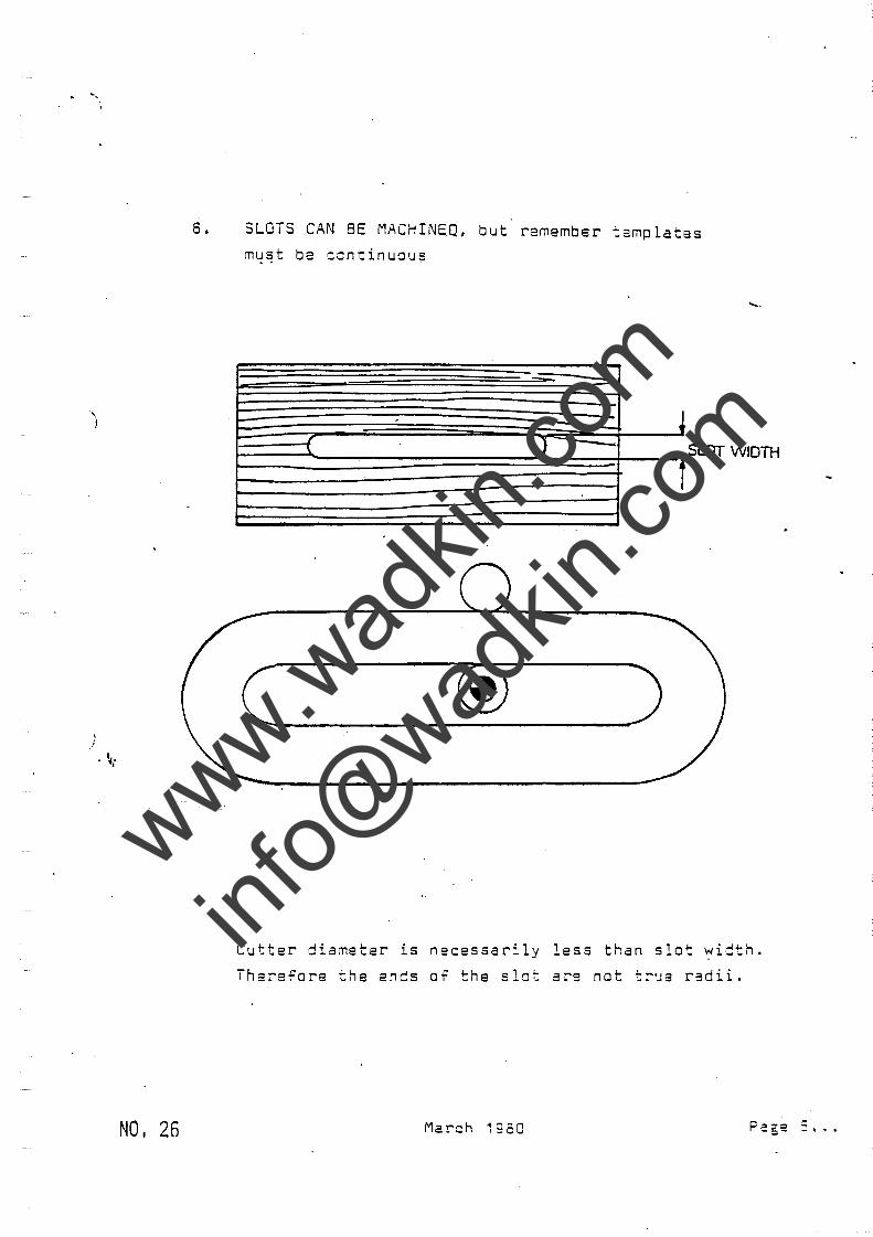
6. SLOTS CAN BE MACHINEQ, but remember templates
m~~t be continuous
-. ~ -
.......
...f J - SlOT WIDTH
t
c ___ ® __ )
Cutter diameter is necessarily less than slat width.
Therefore the ends of the ·slot are not true r3dii.
March 1980
www.wad
kin.co
m
info@
wadkin
.com
· ~.'
No. 26
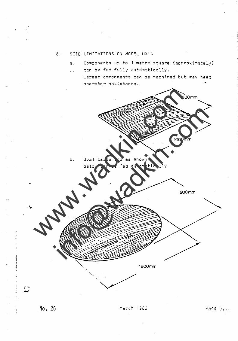
o. SIZE LIMITATIONS ON MODEL UX1A
a. Components up .to 1 metre square (approximately)
can be fed fully automatically.
Larger'components can be machined but may need
operator assistance. .......
1000mm
b. Oval table top as shown
below can be fed automatically
900 mm
1800mm
March 19:50 Page 7 •••
www.wad
kin.co
m
info@
wadkin
.com
. I
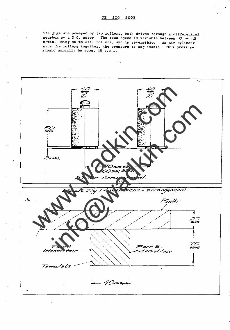
UX JIG BOOK
The jigs are powered by two rollers, both driven through a differential gearbox by a D.e. motor. The feed speed is variable between 0 - IS m/min. using 40 mm dia. rollers, and is reversible; An air cylinder nips the rollers together, the pressure is adjustable. This pressure should normally be about 40 p.s.i.
·1·' . v ... · . . , .. .
~.w.::: So .'.,' ?#L~ ~~f:::
r :"::' .. : .... ........ i.o :"
L70~m/;, /00."""", I'J#.!IX.
.~ .. !:.~:. IO::~~ '.'
0. " ,.. ;; :
-1
~c:>/k.r- r?rr~4He»~.
--------------------~------------------~
. ~ ..
>/;/~>// f::::..--.L--//-L-//-L,' ~/ ~/ ---'--~---1 www.w
adkin
.com
info@
wadkin
.com
, '<,.
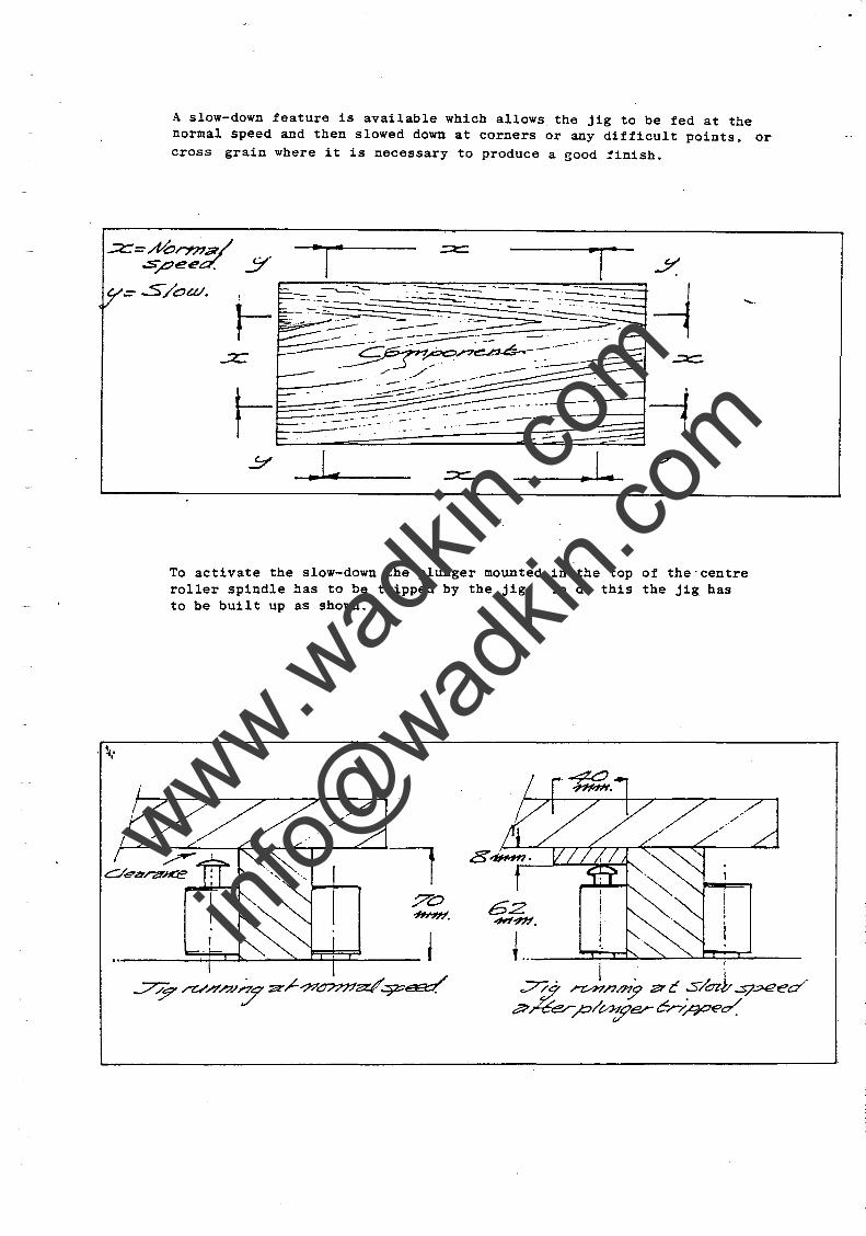
A slow-down feature is available which allows the jig to be fed at the normal speed and then slowed down at corners or any difficult points. or cross grain where it is necessary to produce a good finish.
..... .
. L ,.L
To activate the slow-down the plunger mounted in the top of the'centre roller spindle has to be tripped by the jig. To do this the jig has to be built up as shown.
~ •.. I
;:7:i n1/7~ :?J' C ~/O&t ~.:x?ed a-ner ~/0J'.j?~ c-.r//?Oe~
www.wad
kin.co
m
info@
wadkin
.com
. ~ ..
.... - ---------/
( I
------Z-;1 L/.:1
I I I I I I.., r4CJd1I#f ! I
I I
"\
I I I I
: [:)/1""" 1---14~. \"~ ..LL-r ---
I rl
~, /
."z:::-.?TC' e /1 '
.:..7/9 ~v//C-?lp:;le ".7fe.:se.."ac);'nCa Z ~r~ .s/OtvcYCXV/7 p/t/~er;
_/
The feed speed of the jig when slow-down plunger has activated is also adjustable by means of a control knob on the main panel.
......
www.wad
kin.co
m
info@
wadkin
.com
;z:::;-,,:x ea/' Ci?nb-e Ro//er
C~e.- . //.?/e/:n3/ c.vt:::J,,-4:. "
....c=-.>c::=' .-"9~r::>~ c::>r= T~..s- ~..::::~ ./",u -:;;r-r.,//....:S' ,A-?' ~A/V /9~ •
www.wad
kin.co
m
info@
wadkin
.com
· ~:
......
CC:::>.,(,..I77.vU~) . ~·T.O·
www.wad
kin.co
m
info@
wadkin
.com
......
~~ft //'1'C~/7?a/:'777l":JO/'Lr
-=s-~a.,.aed ~~ v..:s/""J? O?7e Y 'J? 9/7.s/~~~ pr0a0C12P"U/;~ ce 0/'7 /;;??CJ2... A. Ovc.si~
_~-4--"T""4-r--"'--......t:----''---I sh ~e ,.c:~ocea/ CL//d. c.AC? on ".rLa-az.. B' .
www.wad
kin.co
m
info@
wadkin
.com
. ~ ..
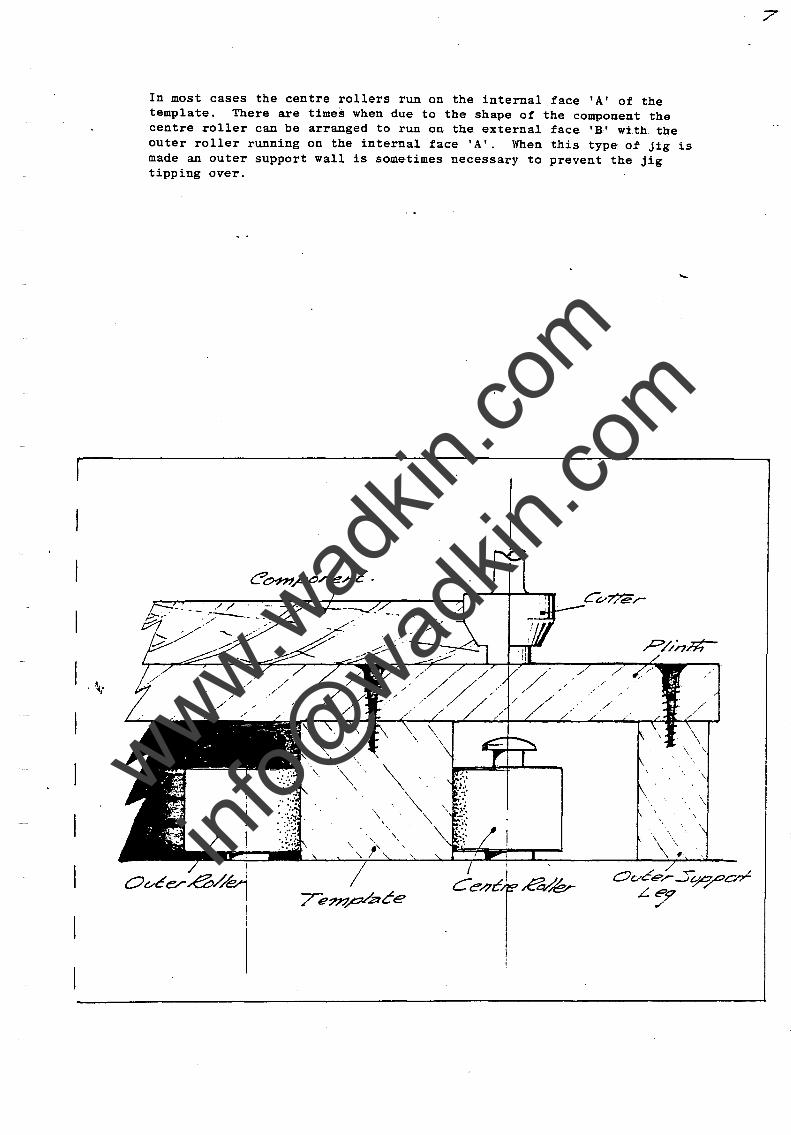
In most cases the centre rollers run on the internal face 'A' of the template. There are times when due to the shape of the component the centre roller can be arranged to run on the external face 'B' with the outer roller running on the internal face 'A'. When this type of jig is made an outer support wall is sometimes necessary to prevent the jig tipping over.
..... .
7
www.wad
kin.co
m
info@
wadkin
.com
. ~.'
CONSTRUCTION OF TEMPLATES
Templates can be produced by glueing together several sheets of good quality hard plywood to a height of 70 mm.
The face which the centre roller runs on has to be very accurate as any imperfections will be reproduced on the finished component. This face should be sanded. The face which tpe outer roller runs on is not as critical but should be reasonably smooth to ensure a good roller life. This face should not however be polished or sanded.
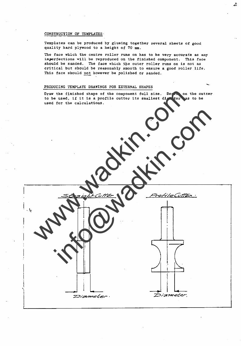
PRODUCING TEMPLATE DRAWINGS FOR EXTERNAL SHAPES
Draw the finished shape of the component full size. Decide on the cutter to be used, if it is a profile cutter its smallest diameter has to be used for the calculations .
I'
It
www.wad
kin.co
m
info@
wadkin
.com
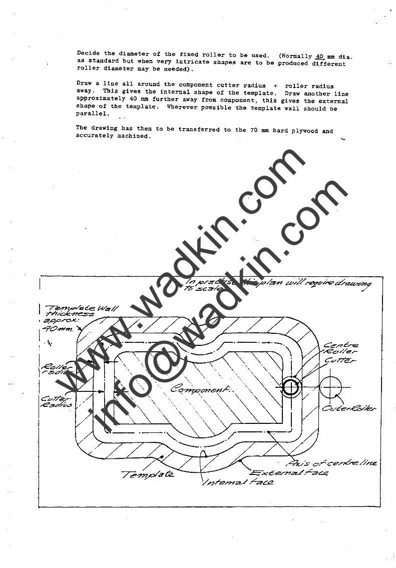
Decide the diameter of the fixed roller to be used. (Normally.iQ. mm dia. as standard but when very intricate shapes are to be produced different roller diameter may be needed).
Draw a line all around the component cutter radius + roller radius away. This gives the internal shape of the template. Draw another line approximately 40 mm fUrther away from component, this gives the external shape of the template. Wherever. possible the template wall should be parallel.
The drawing has then to be transferred to the 70 mm hard plywood and accurately machined. ......
-r-~..-e:o/a Ce. Wzz // 777/~~~ ____ ~~-------?----~
, Sr',r'rox.:
I-904H"ffl .
. ~ ..
. ;4/s o;r::ce.n6e//~ ~ x-cEe.rna../ rZ?t::.€
y n r en7a-/ ~ao::z.
www.wad
kin.co
m
info@
wadkin
.com
. ~"
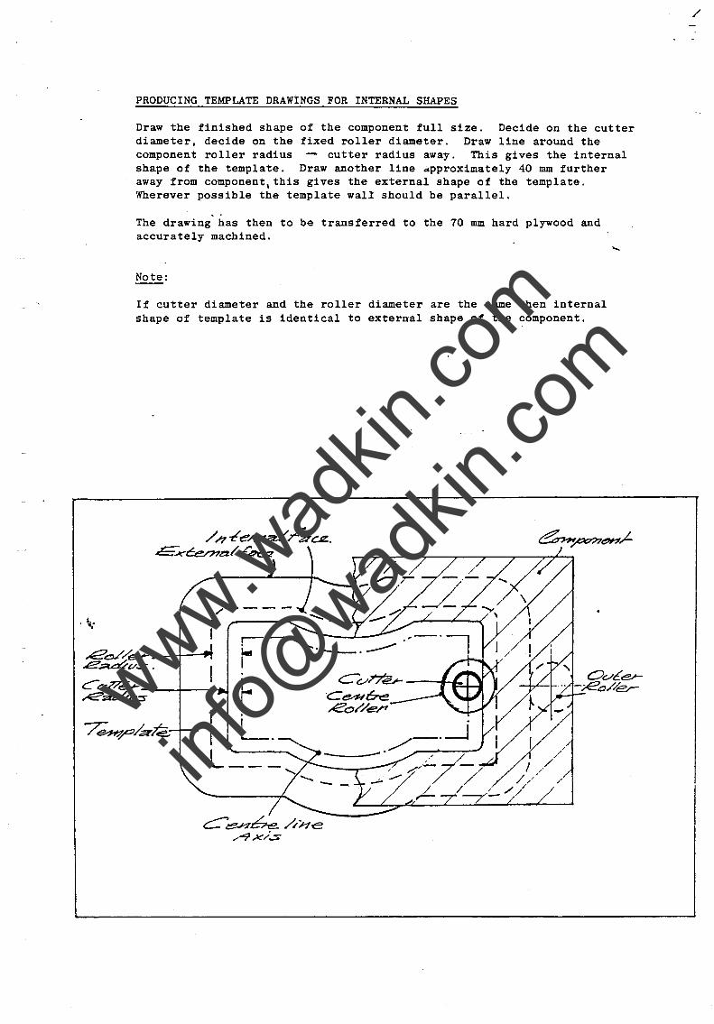
PRODUCING TEMPLATE DRAWINGS FOR INTERNAL SHAPES
Draw the finished shape of the component full size. Decide on the cutter diameter, decide on the fixed roller diameter. Draw line around the component roller radius -- cutter radius away. This gives the internal shape of the template. Draw another line approximately 40 mm further away from component, this gives the external shape of the template. Wherever possible the template wall should be parallel.
The drawing has then to be transferred to the 70 mm hard plywood and accurately machined.
Note:
If cutter diameter and the roller diameter are the same then internal shape of template is identical to external shape of the component.
/ h "t!e/n~ hcrz.. £""..,J('"C:en7zz/ ,.r~
...e~/er _-t-~..,. .e~v.:s.
C&I'7/e..,.... ~a~~-----+--~~
/
www.wad
kin.co
m
info@
wadkin
.com
www.wad
kin.co
m
info@
wadkin
.com
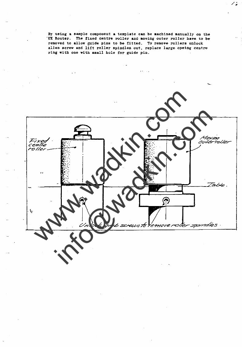
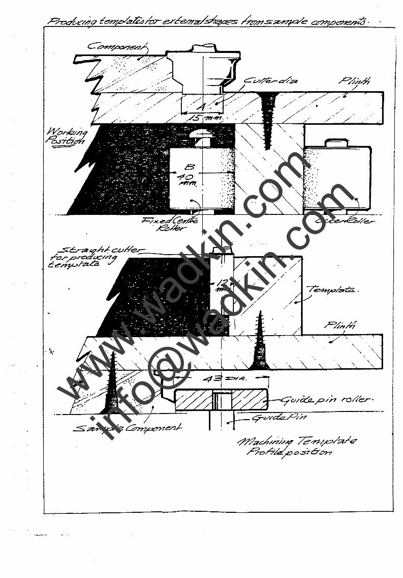
By using a sample component a template can be aachined manually on the 'UX Router. The fixed centre roller and moving outer roller have to be removed to allow ~ide pins to be fitted. To remove rollers unlock alIen screw and lift roller spindles out, replace large opeing centre ring with one with small hole for guide pin.
kxe/ . c~//i;g rr;J//er-
. ~,.
/;
www.wad
kin.co
m
info@
wadkin
.com
./
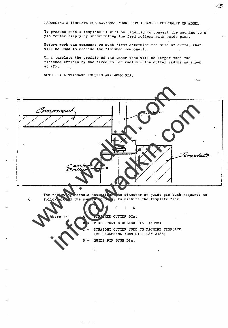
PRODUCING A TEMPLATE FOR EXTERNAL WORK FROM A SAMPLE COMPONENT OF MODEL
To produce such a template it will be required to convert the machine to a pin router simp"ly by substituting the feed rollers with guide pins.
Before work can commence we must first determine the size ot cutter that will be used to machine the finished component.
On a t~mplate the protile o! the inner tace will be larger than the tinished article by the tixed roller radius + the cutter radius as shown a t (X).
NOTE : ALL STANDARD ROLLERS ARE 40MM DIA .
The following tormula determines the diameter ot guide pin bush required to . ~.' tollow around the sample in order to machine the template tace.
Where :-
A + B = C + D
A = FINISHED CUTTER DIA.
B = FIXED CENTRE ROLLER DIA. (40mm)
C = STRAIGHT CUTTER USED TO MACHINE TEMPLATE (WE RECOMMEND 12mm DIA. LSW 3185)
D = GUIDE PIN BUSH DIA.
www.wad
kin.co
m
info@
wadkin
.com
. ~"
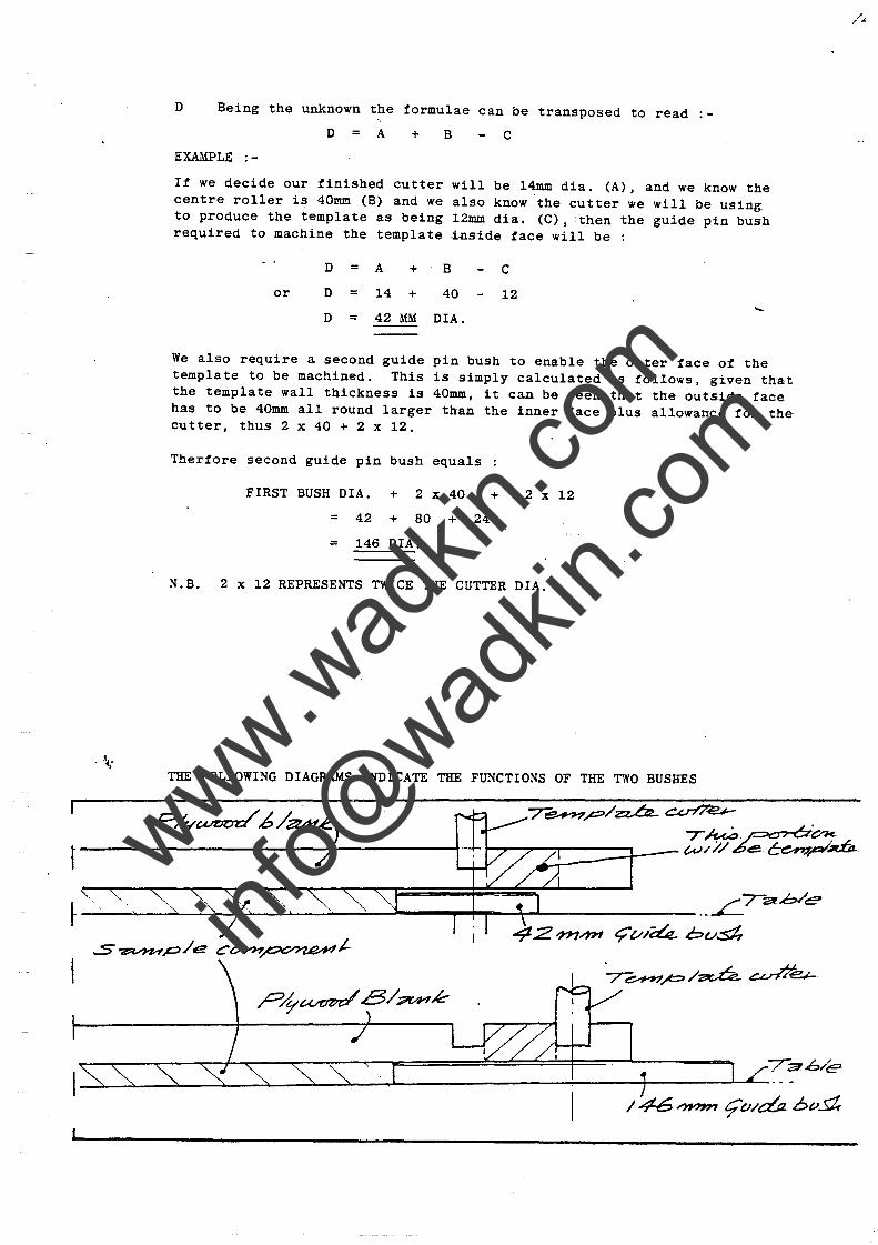
D Being the unknown the formulae can be transposed to read
D = A + B C
EXAMPLE :-
It we decide our tinished cutter will be 14mm dia. (A), and we know the centre roller is 40mm (B) and we also know the cutter we will be using to produce the template as being 12mm dia. (C), -then the guide pin bush required to machine the template i~side tace will be :
or
D = A +
D = 14 +
B
40
D = 42 MM DIA.
C
12 .....
We also require a second guide pin bush to enable the outer tace ot the template to be machined. This is simply calculated as follows, given that the template wall thickness is 40mm, it can be seen that the outside face has to be 40mm all round larger than the inner face plus allowance for the cutter, thus 2 x 40 + 2 x 12.
Thertore second guide pin bush equals
FIRST BUSH DIA. + 2 x 40 + 2 x 12
= 42 + 80 + 24
= 146 DIA.
N.B. 2 x 12 REPRESENTS TWICE THE CUTTER DIA .
THE FOLLOWING DIAGRAMS INDICATE THE FUNCTIONS OF THE TWO BUSHES
~ _~~ ___ ~~~~~~~ ___ ~~ ____ ~~~~ ____________________ .. ~~~h/e ~ t:;v/;;Gz. bust ..s~p/e CO'YH~J-
7-~~/~ ~e.t-
www.wad
kin.co
m
info@
wadkin
.com
. ~.
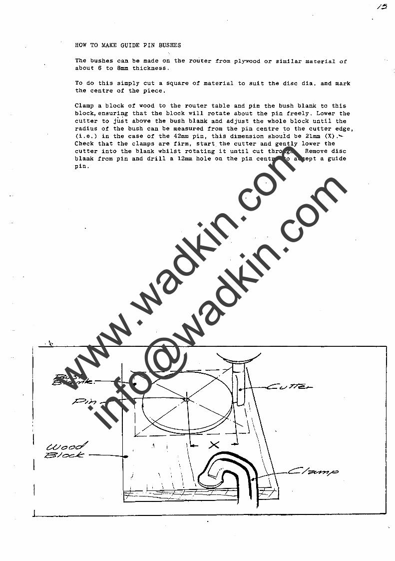
HOW TO MAKE GUIDE PIN BUSHES'
The bushes can be made on the router from plywood or similar material of about 6 to 8mm thickness.
To do this simply cut a square of material to suit the disc dia. and mark the centre of the piece.
Clamp a block of wood to the router table and pin the bush blank to this block, ensuring that the block will rotate about the pin freely. Lower the cutter to just above the bush blank and adjust the whole block until the radius of the bush can be measured from the pin centre to the cutter edge, (i.e.) in the case of the 42mm pin, this dimension shouid be 2lmm (X).'Check that the clamps are firm, start the cutter and gently lower the cutter into the blank whilst rotating it until cut through. Remove disc blank from pin and drill a l2mm hole on the pin centre to accept a guide pin .
www.wad
kin.co
m
info@
wadkin
.com
. ~"
Having now produced suitable guide pin bushes work can now begin on the actual template.
Firstly a suitable piece of 25mm ply should be cut to ·dimensions which are at least Roller radius + Cutter radius + 40mm all the way round the sample.
Secondly a sample or model component should be provided. This sample should be exact and wi thin your specific toleranc.es ,. and should have no irregularities, as these will be reproduced into the template and subsequently onto future components.
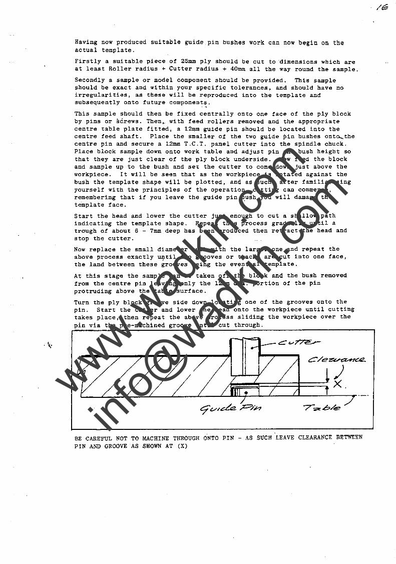
This sample should then be fixed centrally onto one face of the ply block by pins or screws. Then~ with feed rollers removed and the appropriate centre table plate fitted, a l2~ guide pin should be located into the centre feed shaft. Place the smaller of the two guide pin bushes onto.....the centre pin and secure a l2mm T.C.T. panel cutter into the spindle chuck. Place block sample down onto work table and adjust pin and bush height so that they are just clear of the ply block underside. Now feed the block and sample up to the bush and se~ the cutter to come down just above the workpiece. It will be seen that as the workpiece is rotated against the bush the template shape will be plotted, and as such, after familiarising yourself with the principles of the operation, cutting can commence, remembering that if you leave the guide pin b.ush you will damage the template face.
Start the head and lower the cutter just enough to cut a shallow path indicating the template shape. Repeat this process gradually until a trough of about 6 - 7mm deep has been produced then retract the head and stop the cutter.
Now replace the small diameter bush with the larger one and repeat the above process exactly u~til two grooves or tracks are cut into one face, the land between these grooves being the eventual template.
At this stage the sample can be taken of! the block and the bush removed from the centre pin leaving only the l2mm dia. portion of the pin protruding above the table surface.
Turn the ply block groove side down locating one of the grooves onto the pin. Start the cutter and lower the head onto the workpiece until cutting takes place, then repeat the above process sliding the workpiece over the pin via the pre-machined groove until cut through .
BE CAREFUL NOT TO MACHINE THROUGH ONTO PIN - AS SUCH LEAVE CLEARANCE BETWEEN PIN AND GROOVE AS SHOWN AT (X)
. /6
www.wad
kin.co
m
info@
wadkin
.com
Repeat same procedure on second groove, teeding downwards gradually at each pass about 3mm until cut. through.
NOTE
WHEN MACHINING ABOVE PROCEDURES DO NOT CLIMB CUT, AS TO DO SO CAN CAUSE CUTTER TO SNATCH AT WORKPIECE. FEED SMOOTHLY WITH HANDS SPACED AWAY FROM CUTTER.
IN MOST CASES IT WILL BE FOUND EASIER WHEN CUTTING GROOVES TO MACHINE DOWN TILL THE TWO ALMOST ~1EET BUT LEAVfNG A THIN VENEER BETWEEN, THUS ALLOWING THE WASTE TO BE BROKEN AWAY BY HAND. (i.e.)
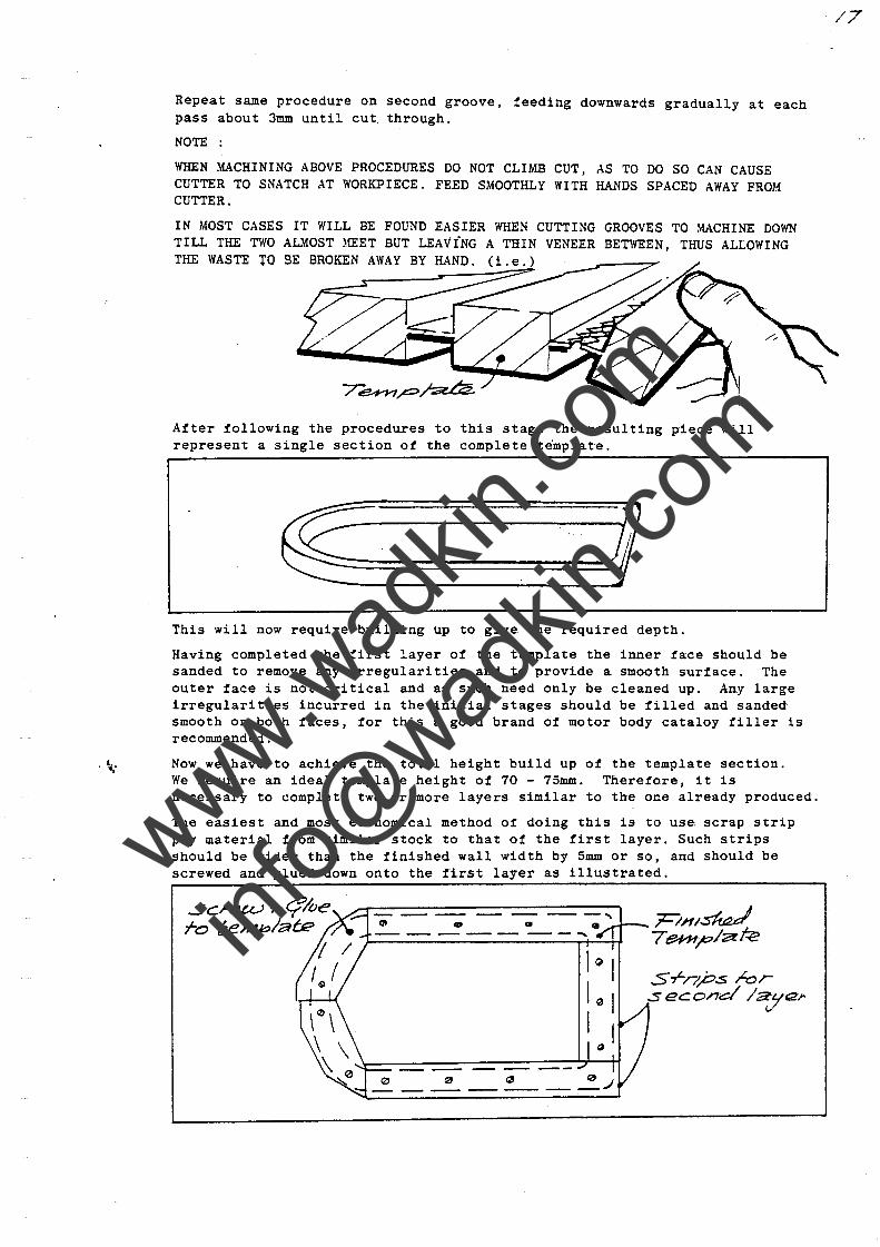
After following the procedures to this stage the resulting piece will represent a single section ot the complete template.
This will now require building up to give the required depth.
Having completed the tirst layer ot the template the inner tace should be sanded to remove any irregularities and to provide a smooth surtace. The outer tace is not critical and as such need only be cleaned up. Any large irregularities incurred in the initial stages should be tilled and sanded smooth on both taces, tor this a good brand ot motor body cataloy tiller is recommended .
. ~" Now we have to achieve the total height build up ot the template section. We require an ideal template height ot 70 - 75mm. Theretore, it is necessary to complete two or more layers similar to the one already produced.
The easiest and most economical method ot doing this is to use scrap strip ply material trom similar stock to that ot the tirst layer. Such strips should be wider than the tinished wall width by 5mm or so, and should be screwed and glued down onto the tirst layer as illustrated.
-- -- - -- ---" ~ " 0.) ------------
Srnps ,La, sec.ond /aJl~)o
/7
www.wad
kin.co
m
info@
wadkin
.com
, ~.'
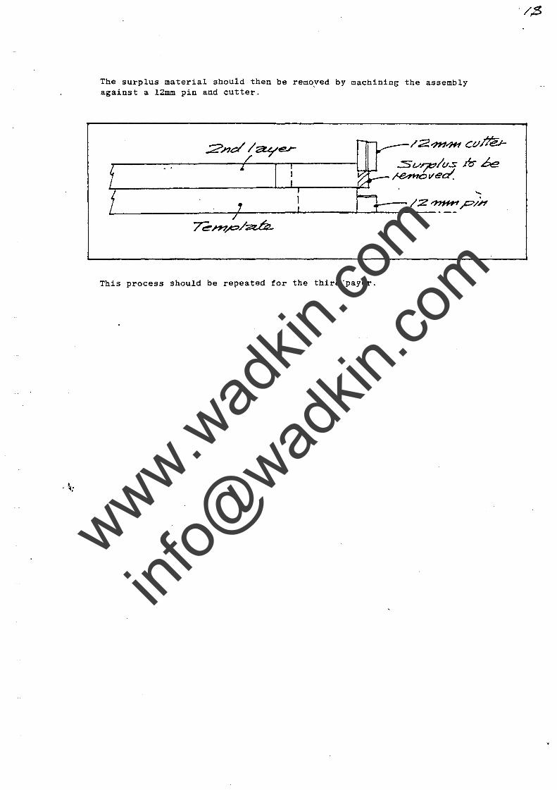
The surplus material should then be removed by machining the assembly against a l2mm pin and cutter.
This process should be repeated tor the third 'payer.
/;2?n"iH Ct.lJ7:v
.:s(./~/t./S m k ~ved.
",
www.wad
kin.co
m
info@
wadkin
.com
, ~"
PRODUCING TEMPLATES FOR INTERNAL WORK FROM S~~LE COMPONENTS OR MODELS
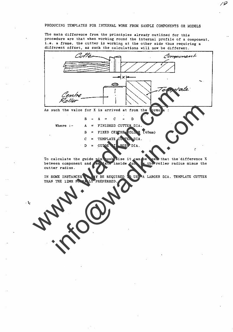
The main difference from the principles already outlined for this procedure are that when working round the internal profile of a component, i.e. a frame, the cutter is workin~ at the other side thus requiring a different offset, as such the calculations will now be different.
As such the value tor X is arrived at from the formula
B A = C D
Where :- A = FINISHED CUTTER DIA.
B = FIXED CENTRE ROLLER (40mm)
C = TEMPLATE CUTTER DIA.
D = GUIDE PIN BUSH DIA. r.
To calculate the guide pin bush size it can be seen that the'difference X between component and template inside face is the roller radius minus the cutter radius.
IN so~m INSTANCES IT MAY BE REQUIRED TO USE A LARGER DIA. TEMPLATE CUTTER THAN THE l2ID.1 NORMALLY PREFERRED.
www.wad
kin.co
m
info@
wadkin
.com
· ~"
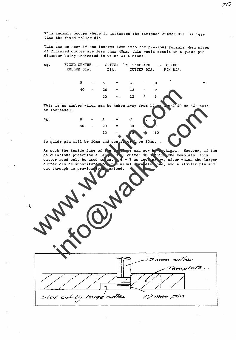
This anomaly occurs wherein instances the finished cutter dia. is less than the fixed roller dia.
This can be seen if one inserts 12mm into the previous formula when sizes of finished cutter are less than 40mm, this would result in a guide pin diameter being indicated in value as a minus.
ego FIXED CENTRE RQL.LER DIA.
B
40
CUTTER DIA.
A
20
20
=
=
This is no number which can be taken be increased.
ego B A = 40 20
20 =
So guide pin will be 10mm and centre
= TEMPLATE CUTTER DIA.
C
12
12
away
C
30
30
from 12
D
?
?
to
D
D
10
will. be 30mm.
GUIDE PIN DIA.
equal 20 so 'C' must
As such the inside face of the template can now be machined. However, it the calculations prescribe a larger dia. cutter to machine the template, this cutter need only be used to cut a 6 - 7 mm deep groove after which the larger cutter can be substituted tor the usual l2mm dia. one, and a similar pin and cut through as previously described.
20
www.wad
kin.co
m
info@
wadkin
.com
, '0 ..
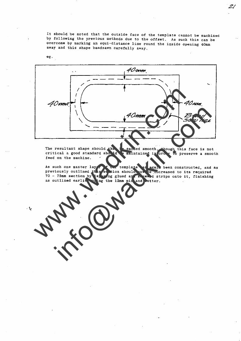
It should be noted that the outside face of the template cannot be machined by following the previous methods due to the offset. As such this can be overcome by marking an equi-distance line round the inside opening 40mm away and this shape bandsawn carefully away.
ego
---------
40.#l1li.
'- --- -- -- ."
The resultant shape should then be sanded smooth, though this face is not critical a good standard should be maintained in order to preserve a smooth feed on the machine.
As such one master layer of our template has again been constructed, and as previously outlined this section should now be ,increased to its required 70 - 75mm section by layering glued and screwed strips onto it, finishing as outlined earlier using the l2mm pin and cutter.
www.wad
kin.co
m
info@
wadkin
.com
·10"
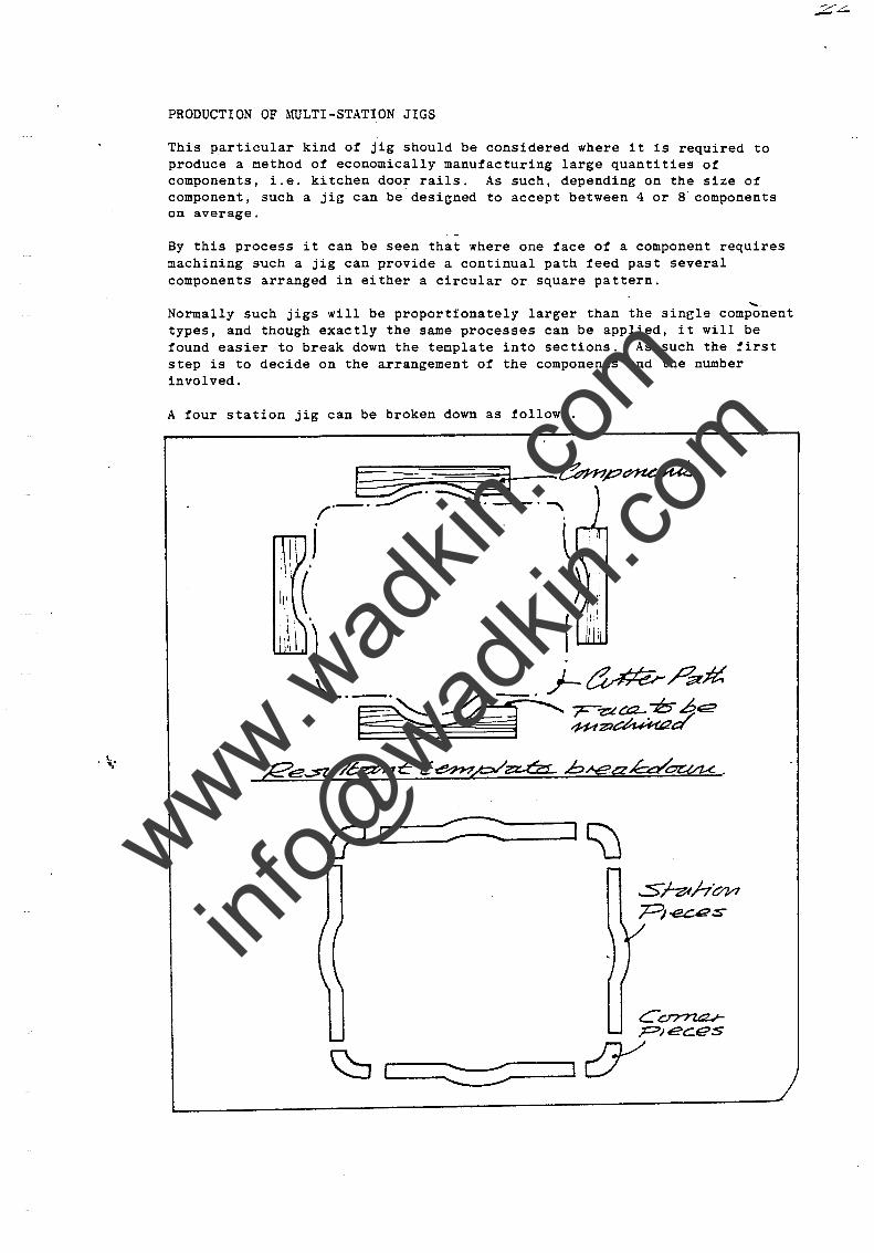
PRODUCTION OF ~ruLTI-STATION JIGS
This particular kind of jig should be considered where it is required to produce a method of economically manufacturing large quantities of components, i.e. kitchen door rails. As such, depending on the size of component, such a ji~ can be designed to accept between 4 or 8 components on average.
By this process it can be seen that where one face of a component requires machining such a jig can provide a continual path feed past several components arranged in either a circular or square pattern.
...... Normally such jigs will be proportionately larger than the sinele component types, and though exactly the same processes can be applied, it will be found easier to break down the template into sections. As such the first step is to decide on the arrangement of the components and the number involved.
A four station jig can be broken down as follows.
~~~=?-~ ......... ~tZ3~t-.~P~ f'-'~'~·-·"-,\ .
J
I,', (
)
.----::::=:::---www.wad
kin.co
m
info@
wadkin
.com
, ~.'
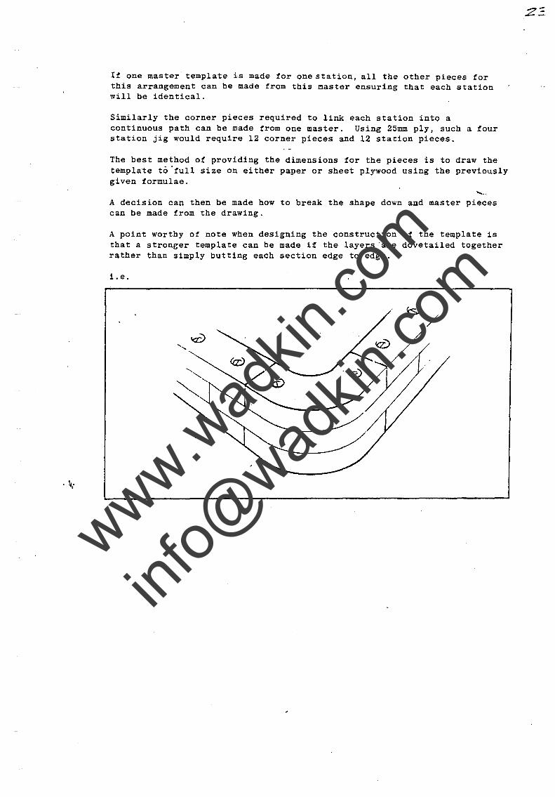
If one master template is made for one station, all the other pieces for this arrangement can be made from this ~aster ensuring that each station will be identical.
Similarly the corner pieces required to link each station into a continuous path can be made from one master. Using 25mm ply, such a four station jig would require 12 corner pieces and 12 station pieces.
The best method of providing the dimensions for the pieces is to draw the template to 'full size on either paper or sheet plywood using the previously given formulae.
A decision can then be made how to break the shape down and master pieces can be made from the drawing.
A point worthy of note when designing the construction of the template is that a stroneer template can be made if the layers 'are dovetailed together rather than simply butting each section edge to edge.
1.e.
www.wad
kin.co
m
info@
wadkin
.com
. ~ ..
An alternative, though more exacting method ot producing the template, is to mark out the entire template profile on sheet ply and then bandsaw and sand to the marked lines. Once a full single layer has been made in this fashion strips can then be fixed onto this layer, and as previously described the surplus material routed away using the pin method.
Having produced the template the next requirement is that of a top board. Consideration should be given to t4e physical size of this board, especially where a routex type dust hood is fitted to the machine, as it is an advantage to'have the brush curtain of the extractor always on top of the board and not hanging over the edge. This ensures total enclosure of the suction effort thus giving less chance of dust being expelled in the ,_ operators area.
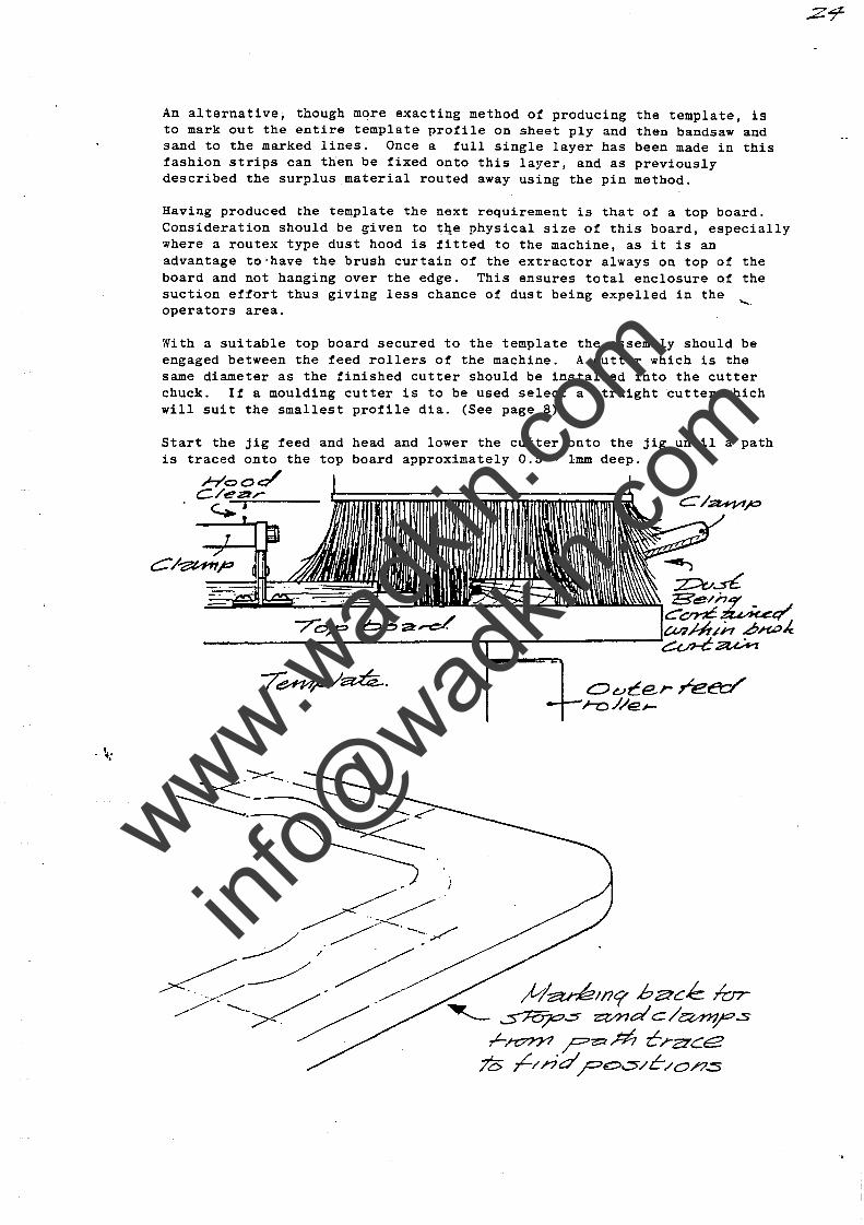
With a suitable top board secured to the template the assembly should be engaged between the feed rollers of the machine. A cutter which is the same diameter as the finished cutter should be installed into the cutter chuck. If a moulding cutter is to be used select a straight cutter which will suit the smallest profile dia. (See page 8)
Start the jig feed and head and lower the cutter onto the jig until a path is traced onto the top board approximately 0.5 - 1mm deep.
Hoo~ C/eDr ~J
#-a;r;6//7? b a-C~ /or ~ ~s z:vndc/a411r'.:s r-~ ?z::th? CrZ2'ce
70 ,L/;·;d ?o-=s/C/o/?.:s
www.wad
kin.co
m
info@
wadkin
.com
. ~"
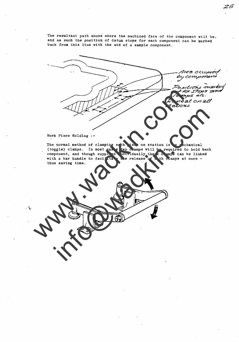
The resultant path showi where the machined face of the component will be, and as such the position of datum stops for each component can be marked back from this line with the aid of a sample component.
Work Piece Holding :-
/1I'€Zl 0 <= ~Ur¥~ ~CO???r'~~
~ __ -::::-;r'-::::::::;-t=,.... ;z:::b..;s'n!:/cnia :;,.., a~1 - ~rbr~s~a'
c./a.-.ffl~ en:. Re,..oeac on;zd .st zz.:b(;:.?(...a
The normal method of clamping each piece on station is by mechanical (toggle) clamps. In most cases two clamps will be required to hold back component, and though supplied individually these clamps can be linked with a bar handle to facilitate the release of both clamps at once -thus saving time .
www.wad
kin.co
m
info@
wadkin
.com
·1
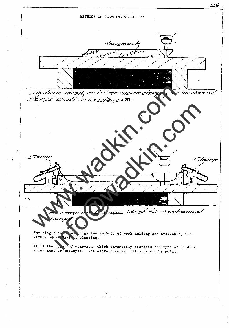
METHODS OF CLAMPING WORKPIECE
/'
1_-
.. ~ - . - ~.~,
, " . • :' :,' ,''''''f
.... ~. ~. .-1'~"'''' ......... ~
, .'. I - .~. \, .- ': '.~ ~ . ..! .....
I ~ __ •
/9 Ct7~'pone;-/C .s:h~t2 ;de~ ~r?n~ch~;;/C2Ut' C/~~.s:-. "
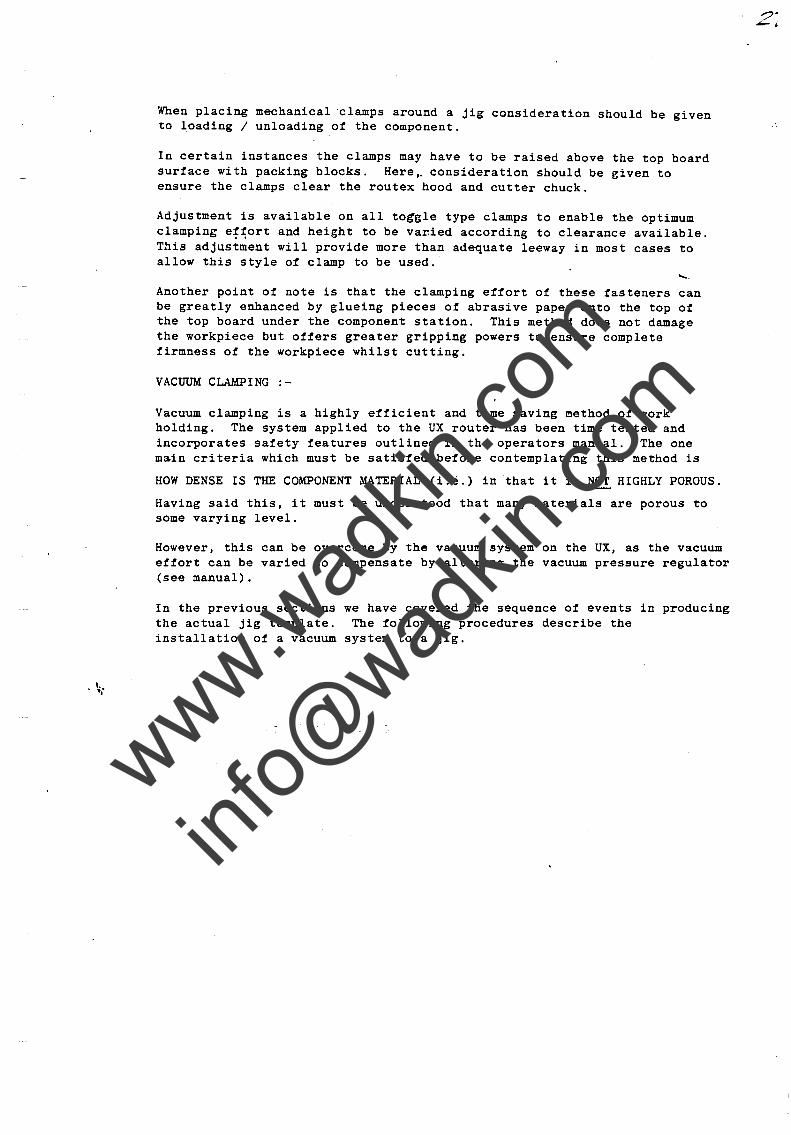
For single component jigs two methods ot work holding are available, i.e. VACUUM or MECHANICAL clamping.
It is the types ot component which invariably dictates the type ot holding which must be employed. The above drawings illustrate th1s point.
.zG
www.wad
kin.co
m
info@
wadkin
.com
.~
When placing mechanical clamps around a jig consideration should be given to loading / unloading of the component.
In certain instances the clamps may have to be raised above the top board surface with packing blocks. Here,. consideration should be given to ensure the clamps clear the routex hood and cutter chuck.
Adjustment is available on all to~gle type clamps to enable the optimum clamping e~~ort and height to be var.ied according to clearance available. This adjustment will provide more than adequate leeway in most cases to allow this style of clamp to be used.
Another point of note is that the clamping effort of these fasteners can be greatly enhanced by glueing pieces of abrasive paper onto the top of the top board under the component station. This method does not damage the workpiece but offers greater gripping powers to ensure complete firmness of the workpiece whilst cutting.
VACUUM CLM!PING :-
Vacuum clamping is a highly efficient and time saving ~ethod of work holding. The system applied to the UX router has been time tested and incorporates safety features outlined in the operators manual. The one main criteria which must be satisfed before contemplating this method is
HOW DENSE IS THE COMPONENT MATERIAL (i.e.) in that it is NOT HIGHLY POROUS.
Having said this, it must be understood that many materials are porous to some varying level.
However, this can be overcome by the vacuum system on the UX, as the vacuum effort can be varied to compensate by altering the vacuum pressure regula.tor (see manual).
In the previous sections the actual jig template. installation of a vacuum
we have covered the sequence of events The following procedures describe the
system to a jig.
in producing
www.wad
kin.co
m
info@
wadkin
.com
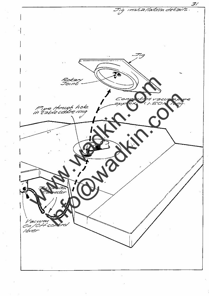
CONSTRUCTING A VACUUM FACILITY
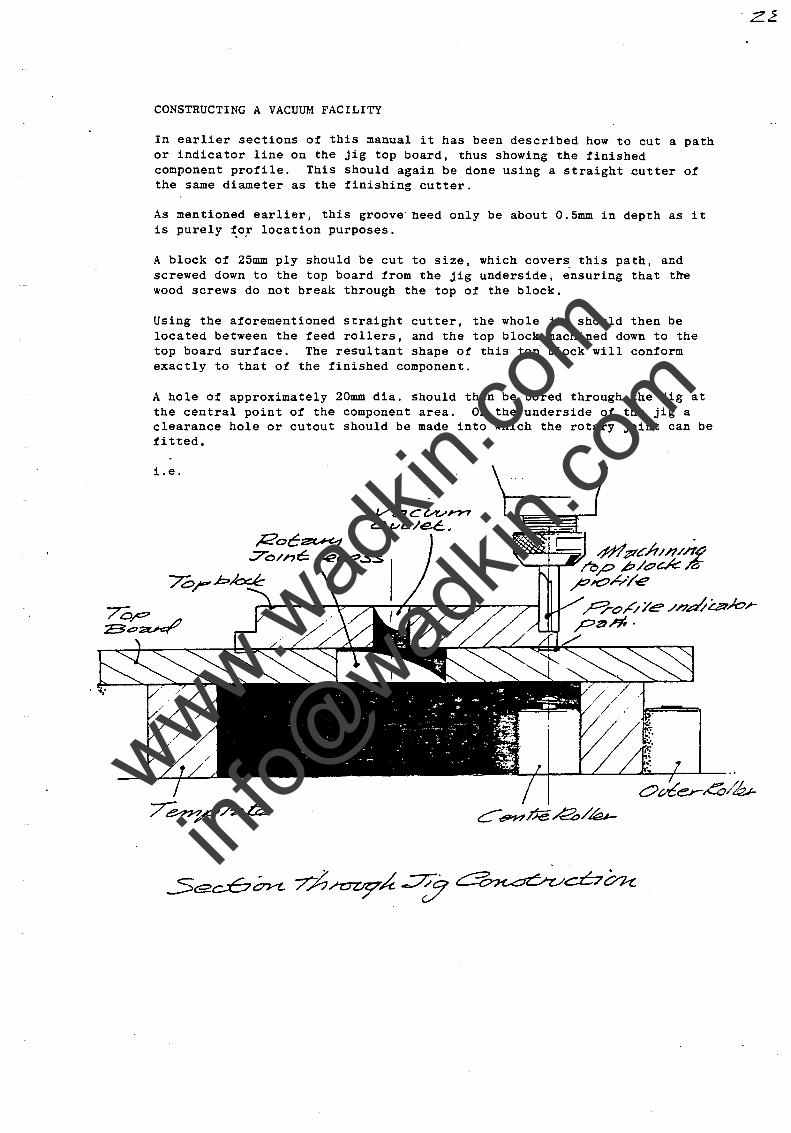
In earlier sections of this manual it has been described how to cut a path or indicator line on the jig top board, thus showing the finished component profile. This should again be done using a straight cutter of the same diameter as the finishing cutter.
As mentioned earlier, this groove need only be about O.5mm in depth as it is purely ~o! location purposes.
A block of 25mm ply should be cut to size, which covers. this path, and screwed down to the top board from the jig underside, ensuring that the wood screws do not break through the top of the block.
Using the aforementioned straight cutter, the whole jig should then be located between the feed rollers, and the top' block machined down to the top board surface. The resultant shape of this to~ block will conform exactly to that o! the finished component.
A hole of approximately 20mm dia. should then be bored through the jig at the central point of the component area. On the underside of the jig a clearance hole or cutout should be made into which the rotary joint can be fitted.
i.e.
Vz:;1cvvrn o (..Il!;-/~ •
Roc~ ..7.o/ne: 142Cl?.:sS
70rbkxk
www.wad
kin.co
m
info@
wadkin
.com
. ~.'
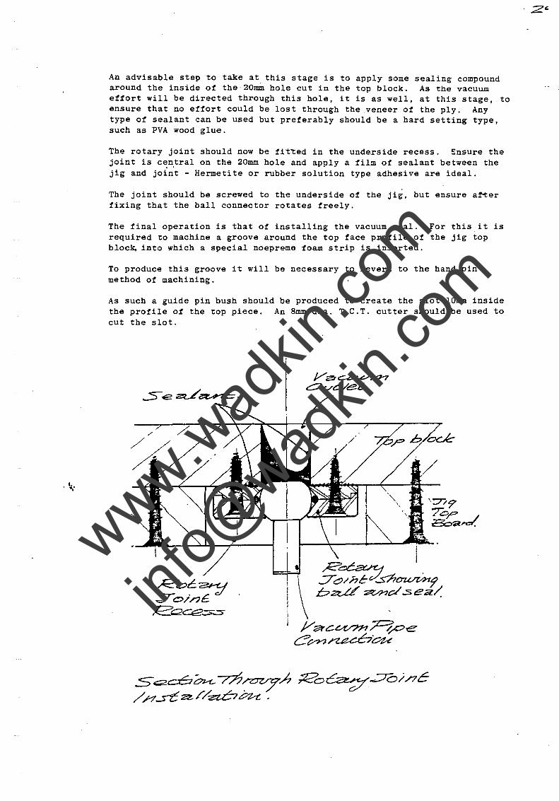
An advisable step to take at this stage is to apply some sealing compound around the inside of the 20mm hole cut in the top block. As the vacuum eftort will be directed through this hole, it is as well, at this stage, to ensure that no effort could be lost through the veneer of the ply. Any type of sealant can be used but preferably should be a hard setting type, such as PVA wood glue.
The rotary joint should now be fit~ed in the underside recess. Ensure the joint is cen,tral on the 20mm hole and apply a film of sealant between the jig and joint - Hermetite or rubber solution type adhesive are ideal.
The jOint should be screwed to the underside of the jig, but ensure arter fixing that the ball connector rotates freely.
The final operation is that of installing the vacuum seal. For this it is required to machine a groove around the top face profile of the jig top bloc~ into which a special noepreme foam strip is inserted.
To produce this groove it will be necessary to revert to the hand pin method of machining.
As such a guide pin bush should be produced to create the slot IOmm inside the profile ot the top piece. An 8mm dia. T.e.T. cutter should be used to cut the slot.
/'
/
. ;zc.
www.wad
kin.co
m
info@
wadkin
.com
. ~ ..
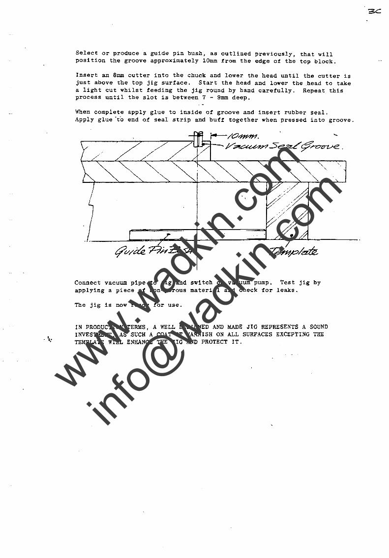
Select or produce a guide pin bush, as outlined previously, that will position the groove approximately lOmm from the edge of the top block.
Insert an 8mm cutter into the chuck and lower the head until the cutter is just above the top jig surface. Start the head and lower the .head to take a light cut whilst feeding the jig round by hand carefully. Repeat this process until the slot is between 7 - 9mm deep.
When complete apply glue to inside of groove and insert rubber seal. Apply glue "to end of seal strip and buff together when pressed into groove.
Connect vacuum pipe to jig and switch on vacuum pump. Test jig by applying a piece of non-porous material and check for leaks.
The jig is now ready for use.
IN PRODUCTION TERMS, A WELL DESIGNED AND MADE JIG REPRESENTS A SOUND INVESTMENT, AS SUCH A COAT OF VARNISH ON ALL SURFACES EXCEPTING THE TE~£pLATE WILL ENHANCE THE JIG AND PROTECT IT.
www.wad
kin.co
m
info@
wadkin
.com
-I
I
I
J/;;;;TC C/V'?H' O'yOH CO/.JCn:V /eve;-
3/
www.wad
kin.co
m
info@
wadkin
.com
~ , .
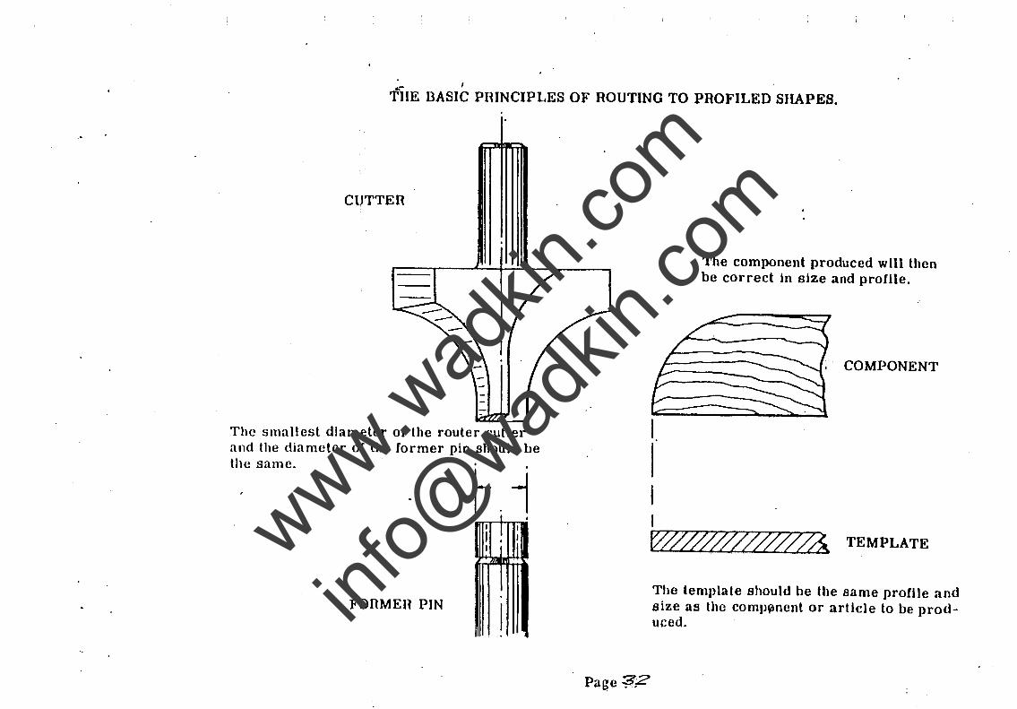
THE DASIC PRINCIPLES OF ROUTING TO PROFILED SHAPES.
CUTTER
The smallest diameter of the router cutter and the diameter of the former pin should be the same.
• I . I ! I I I I U
FonMEIl PIN
I
The component produced will then be correct in size and profile.
COMPONENT
W~~hi TEMPLATE
Page ?,2
The template should be the same profile and size as the comJl~nent or article to be produeed.
www.wad
kin.co
m
info@
wadkin
.com
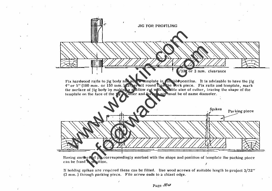
JIG FOil PROFILING
f 3/32" or 3 mm. clearance
Fix hardwood rails to jig body and screw template in suitable posItion. It Is advisable to have the jig 4" or 5/1 (100 mm. or 150 mm.) larger all round than the work piece. Fix rails and template, marl{ the surface of jig body by making a shallow cut with suitable size of cutter, tracing the shape of the template 011 the face of the jig. Cutter and (ormer pin must be of same diameter.
Spikes ., Paeking piece
JIavillR surface of jig corresponc;iingly marked with lhe shape and position of template the packing piece cal\ be fixed In position.
I
H holding spikes arc required these can be fitted. Use wood screws of suitable length to project 3/32" (3 mm. ) through pacldllg piece. File screw ends to a chisel edge.
Page -P.;4
www.wad
kin.co
m
info@
wadkin
.com
~ -.
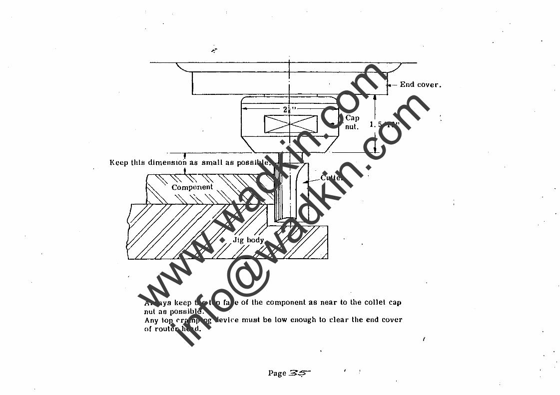
- End cover.
f Keep this dimensIOn as small as possible. ~-+-..a...-
Cap nut. 1. 5/16"
_L Cutter
Always keep the top face of the component as near to the collet cap nul as possible. Any top cramping device must be low enough to clear the end cover of router head_
Page 3.:!;>
(
www.wad
kin.co
m
info@
wadkin
.com
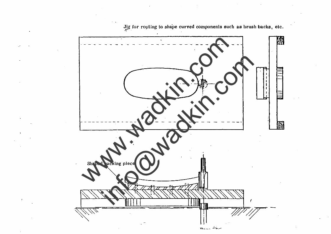
J.!,g (or rOllting to sha'pe curved components Buch as brush backs, etc. -": .
I
www.wad
kin.co
m
info@
wadkin
.com
----------
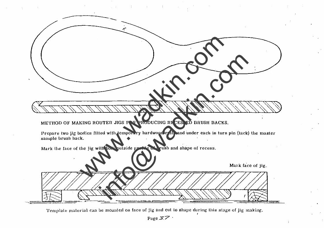
METHOD OF MAKING ROUTER JIGS FOR PRODUCING nECESSED BRUSH DACKS.
Prepare two jig bodies fitted with temporary hardwood ralls and under each in turn pin (tack) the master sanaple llrush llack.
Mark the face of the jig with both outside profile of brush and shape of recess.
MUI'k f.lce of jig.
--- --=---:------
Template material can be mountc.tl on face of jig and cut to shape durinjJ: this stage of jig making. I
Pagc3.7 .
www.wad
kin.co
m
info@
wadkin
.com
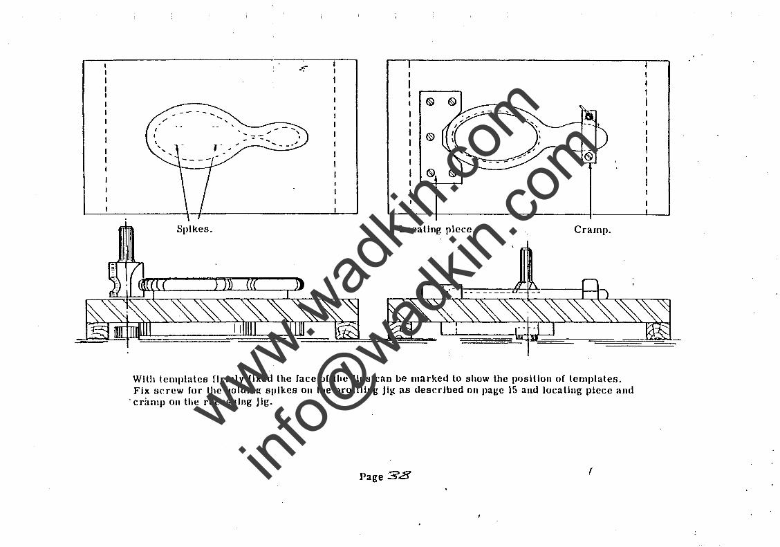
Spikes.
.. --.
;J' - ..... ,
, ...... - -"".I
Locating piece. Cramp.
With templates firmly fixed the face of the Jigs can be marked to show the position of templates. Fix screw (or the holding spikes 011 the I>roflllng Jig as described on page 15 and locating piece and
. critmp on the reecsslng Jig.
Page 38 r
www.wad
kin.co
m
info@
wadkin
.com
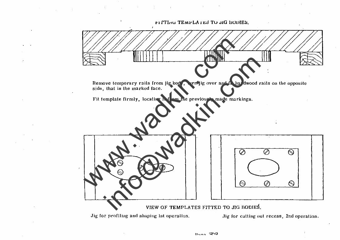
l' 1 fTL~u TEMrLArt;d Tu JiG }jUUIE::;.
llernove temporary rails from jig body, turn jig over and fit hardwood rails on the opposite side, that is the marked face.
Fit template firmly, locating it from the previously made markingtJ.
0 <2> ~
0 § 0 E)
VIEW OF TEMPLATES FITTED TO J1G BODIES.
Jig for profil ing and shaping 1st operation. .Jig for cutting out recess, 2nd operation.
www.wad
kin.co
m
info@
wadkin
.com
I \
/ I
.. --.
~~~-==-~==~~.====~~~
t§> I'----,,----i
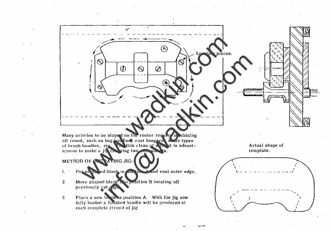
Many arlicles to be shaped on the router require machining all nlllnd, such as bag handles, ,coat hangers, some types of lu'ush handles, etc:. For this class of work it is advunlarcOllS to ll1:1ke a jil{ carrying two components.
METHOD OF OPEHATING JlG:-
I. Put prcpul'ed hlank in position A and roul outer edge.
2 Move shaped bbnk into position B locating off pl'eviou~ly cut edge
Place a new blank in position A. With tl)e jig now ful1y loaded a finished halldle will be produced at each complete circUit of jig
(
Actual shape of template.
_______ .1
I
,
" )
www.wad
kin.co
m
info@
wadkin
.com
~ -.
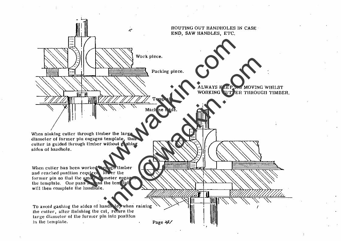
When sinking cutter through timber the large diameter of ronner pin engages template, thus culler' Is guided through limber without gashing sides of handhole.
When culler has been worked through limber and I"cached position required, lower the (OI"mer pin so that the small diameter engages the tcmplate. One pass around the template will then complete the handhole.
ROUTING OUT BANDHOLES IN CASE· EN~, SAW HANDLES, ETC.
Packing piece.
Machine table.
Page ~/
ALWAYS KEEP JIG MOVING WHILST WORKING CUTTER THHOUGII TIMDER.
(
www.wad
kin.co
m
info@
wadkin
.com
.'
1.
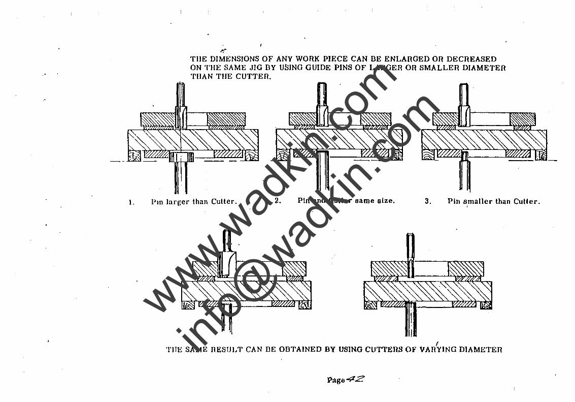
--. TilE DIMENSIONS OF ANY WORK PIECE CAN DE ENLARGED OR DECllEASED ON TilE SAME JIG BY USING GUIDE PINS OF LARGER OR SMALLEll DIAMETER TIIAN THE CUTTER
Pm larger than Cutter. 2. Pln and Cutter same size. 3. Pin smaller than Cutler.
, TilE SAME RESULT CAN DE OBTAINED BY USING CUTTERS OF VARYING DIAMETEll
www.wad
kin.co
m
info@
wadkin
.com
~ -. A.
D.
C.
®
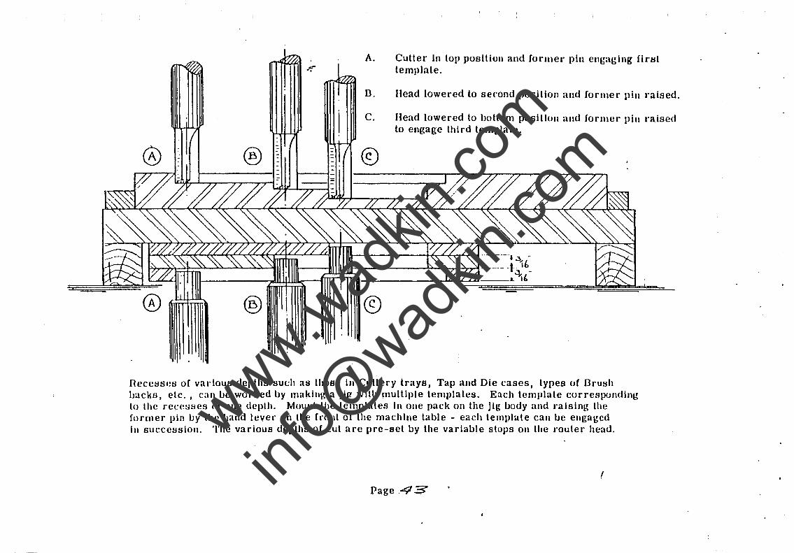
Cutter In top position and fonncr pin engaging first template.
Head lowered to second position and former pin raised.
Head lowered to bottom position and forme.' pill raised to engage third template.
1Lt-------+~'_+_o~~··-·--····,· -
"Il------~~r_rl~,...:.t . ___ ._ . t.3l l.
1----;(~WJh_lnmlTIl 1. '1,-
©
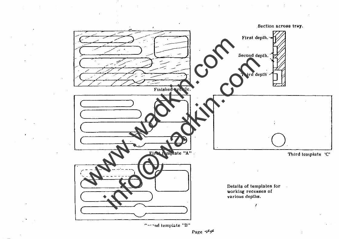
neccssca o( various depths suc:h as those in Cutlery trays. Tap and Die cascs, types of Brush backs, etc., ean l.Je worked by making a Jig wllh multiple templates. Each template corresponding to the recesses or onc depth. Mount thc templates In one pack on the jig IJody and .-alsing the runner pin l.Jy the hand lever on the (ront of thc machine table - each template can IJe engaged III succcsslon. Thc various depths of cut are pre-Bct IJy the variaIJle stops on the .'outer head.
f
Page .43
www.wad
kin.co
m
info@
wadkin
.com
//
~~~~~--~--~~
( )
(
( )
( 2 .,,-- - - - - - -- ---..... I I
""'- - - - - - - - - - - ---"
( )
( ( =
·-
------Finished article.
) )
First template itA 11 :
) )
""'~"'nd template "D" Page 4~
. Section across tray.
First depth.
Second depth.
Third depth"
Details of templates for working recesses of various depths.
(
Third template 'C'
www.wad
kin.co
m
info@
wadkin
.com
~::::=:::::: ... :::::::::::;::=~
,--I
, \ I I
\ .... /
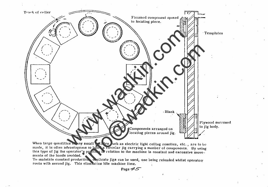
F'IJIIslled component spIKed to locating piece.
.- - ... I
, I I \ I
...... ./
. Dlank
Components arran~ed on locating pieces around jig,
. Templates
Plywood surround lo jig body.
When lal'ge quantities oC any small articles such as electric lIghl ceiling roseUes, etc. , aloe to ue lI1ade, It Is oClcn advantageous {Q build a circular jig carrying a numuer oC components, Dy using lhis type of Jig the operator's position In relation to the machine Is constallt and excessive moveIllCntH of the hands avoided. Tu maintain constant production, duplicate Jigs can be used, one being reloaded whilst oper-atoll rouls with sccond jig. This cllmlnnlcs Idle machine lime. . ,
Page 4ZS
www.wad
kin.co
m
info@
wadkin
.com
I I I I I I
I I I I 1,1 I I
I I I
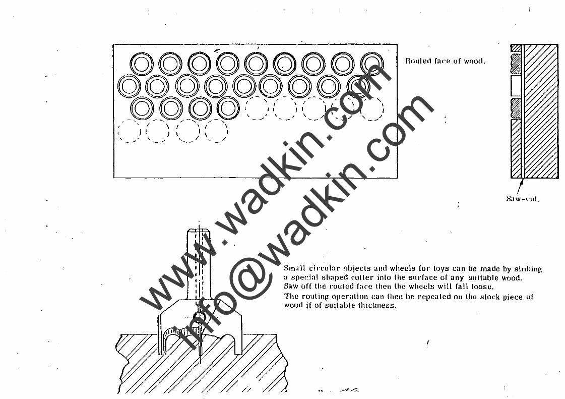
Houted face of wood.
Saw-cut.
Sm..lll circular !"JIJjects and wheels for toys can be made by sinking it special shaped cutler into the surface o( any suitable wood. Saw of( the routed (ace then the wheels will (all loose. The routing operation can then be repeated on the stock piece of wood if of suitable thickness.
,
"' .
www.wad
kin.co
m
info@
wadkin
.com
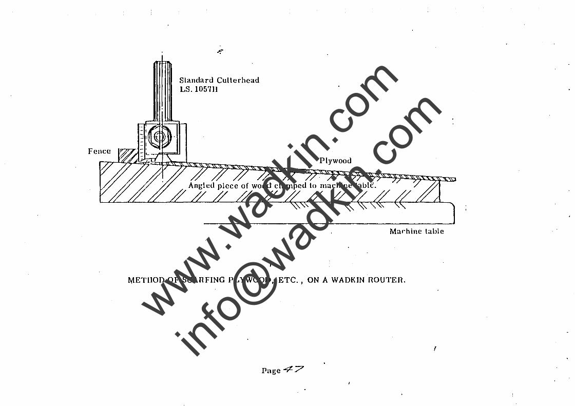
--. Slandard Cullerhcad LS. 105711
Plywood
Marhine lable
METHOD OF SCAHFING PLYWOOD, ETC., ON A WADKIN ROUTEH.
(
Page 47
www.wad
kin.co
m
info@
wadkin
.com
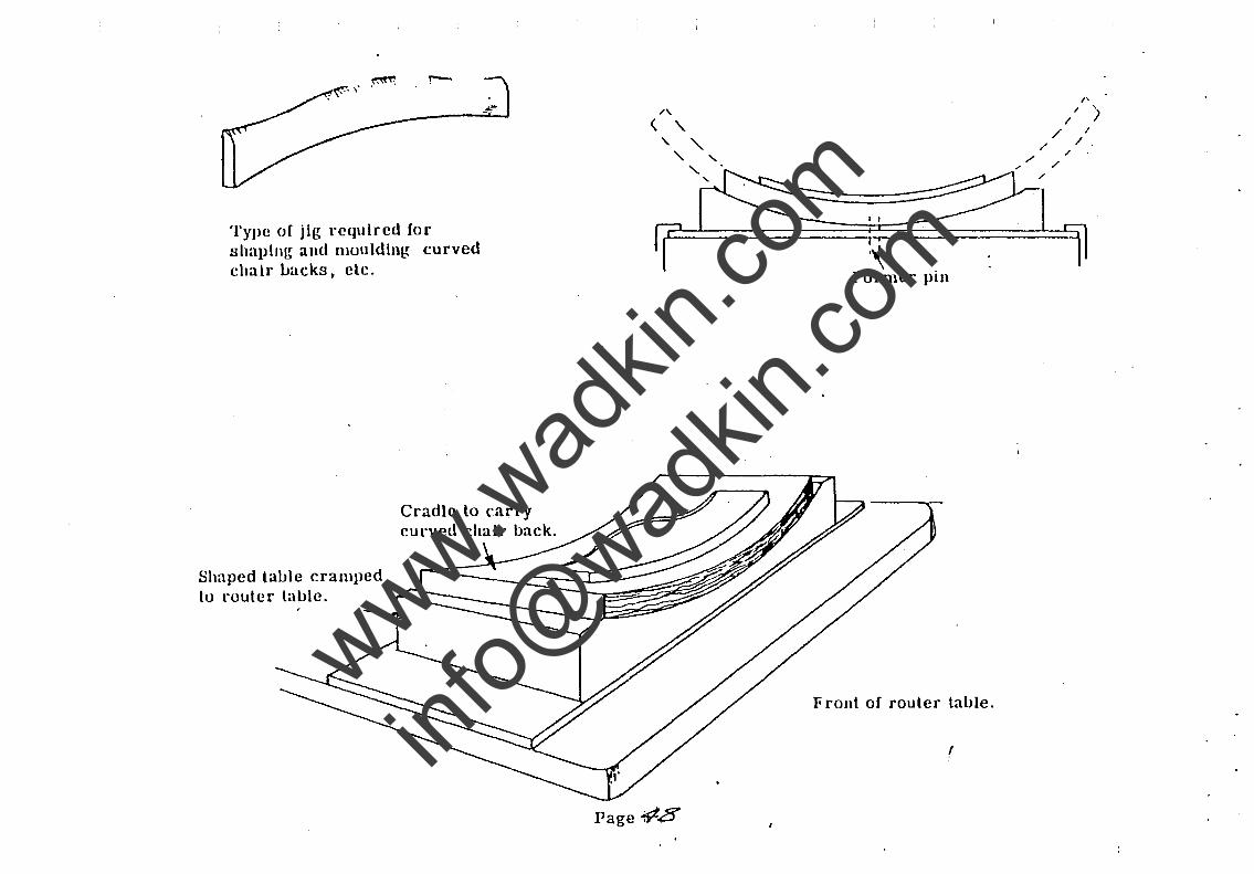
Type of jig required for shaplllg and llloulding curved chalr Lacks, etc.
Shaped lal.Jle cramped tu router lal.Jle.
Cradle to carry curved chair back.
Page #.8'
I I
''\ Former pin
Front of router table.
r
"/ '
/ ) / I
/ /. / .
",./ /
/
www.wad
kin.co
m
info@
wadkin
.com
J[&---- .----
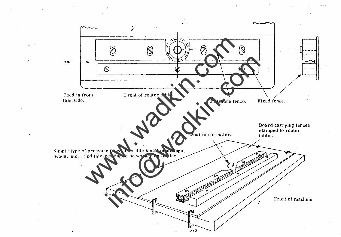
Feed in from this side.
..:--.
Front of router table.
Simple type! of pressure ience to enable small mouldings, bead!;;, etc. , and Ihidme:,;sing 10 be worked on Router.
(§).
Pressure fence.
Position of culler.
Fixed fence.
I
Board carrying fences clamped to router table ..
Front of machine.
www.wad
kin.co
m
info@
wadkin
.com
,
- - ---"" - - - - - - -- - - - - - - - - -
I
-------1
-, ,
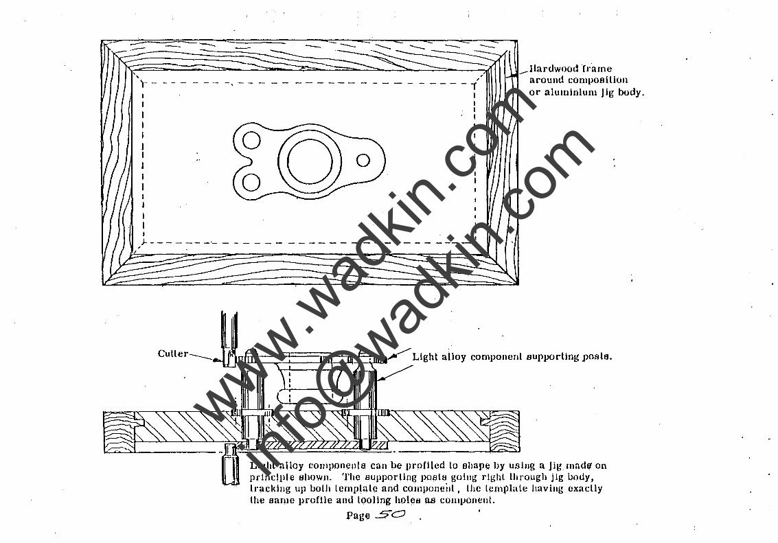
....-Hardwood "frame around cOlllposillon or aluminium jig body.
J- - - - - -- -'- - - - - - -I
- - - - - - - - - - - - - - - -_ --I. '.
l Light alloy component supporting posts.
Light alloy componenls can be profiled to shape by using a Jig madl1 on prillciJlle shown. The supporllng posts goilll{ right through jig body, tracklllg up both template and cOIllPoneilt, the template having exaclly the same profile and tooling holeB as componellt.
Page 50
www.wad
kin.co
m
info@
wadkin
.com
. ,
-
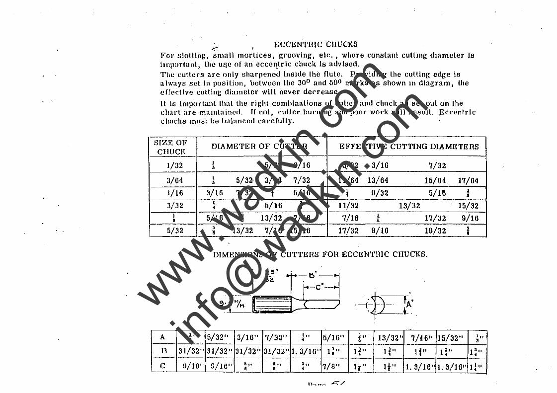
--. ECCENTRIC CHUCKS For slotting, small mortices, grooving, etc., 'Where constanL cutLmg dIameter Is important, lhc u~c of an eccelltrlc chuck Is adviscd. The cullers are only sharpencd insIde the flule. ProvIding the cutting edge Is always sct In position, betwecn lhe 300 and 500 marks as shown 111 diagram, the effective cutting diameter will never decrease. .
It is important that the right combinallons of cutter and chuck as set out on the chart are mainta illcd. If not, cutter burning and poor work will result. ,Eccentric chucks mUl:il Lw balanced carefully.
SIZI!~ OF DIAMETER OF CUTTER EFFECTIVE CUTTING DIAMETERS CHUCK
1/32 I 5/32 3/16 6/32 3/16 7/32 i
3/64 I 5/32· 3/10 7/32 11/64 13/64 15/64 17/04 8
1/10 3/16 7/32 .1 5/16 J 0/32 5/1ft l .. • a 3/32 I 5/16 l 11/32 13/32 I 15/32 .- i
I 5/16 3 13/32 7/16 7/16 I 17/32 9/16 ft i 2"
5/32 l 13/32 7/16 15/16 17/32 9/10 10/32 :i 8 i
DIMENSIONS OF CUTTERS FOR ECCENTIUC CHUCKS.
A J" 5/32" 3/16" 7/32" .1 .. 5/16" 1" 13/32" 7/to ll 15/32" 1" a 1 a 2
B 31/32" 31/32" 31/32 11 31/32" 1. 3/16' 1~1I 1~" nil nil nil 1~" ---C 1)/10" U/16" ~" ~" 1" 7/0" H" HII 1. 3/16" 1. 3/10" It" 11 tI ..
www.wad
kin.co
m
info@
wadkin
.com
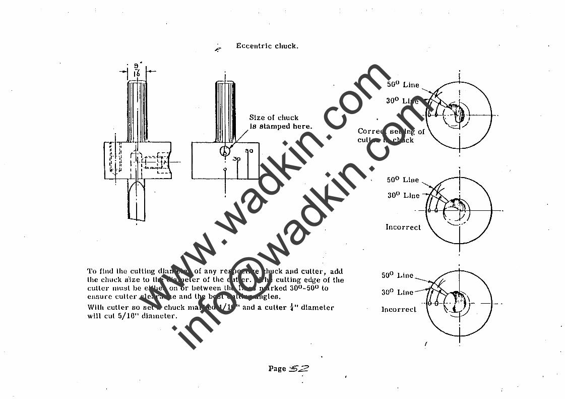
.:--. Eccentclc chuck .
Size oC chuck V is stamped here.
~--~~~.~--~
G~ ~o . ~p
To find the cutting diameter of any respective chuck and culler, add lhe chuck s'ize lo lhe diameler oC lhe culler. The culling edge of the culler llluBL he either on or l.lCtween Lhe lines marked 300 -500 to ensure cullel' cleal'ancc and lhe best cuLling angles.
With cutler 80 set a chuck mal"ked I/lG" and a culler t" diameler will cul 5/10" diameler.
Page 'J£2
500 Line
Correct seltlng of culler in chuck
500 Line
300 Line
Incorrect
500 Line
Incorrecl
I
www.wad
kin.co
m
info@
wadkin
.com
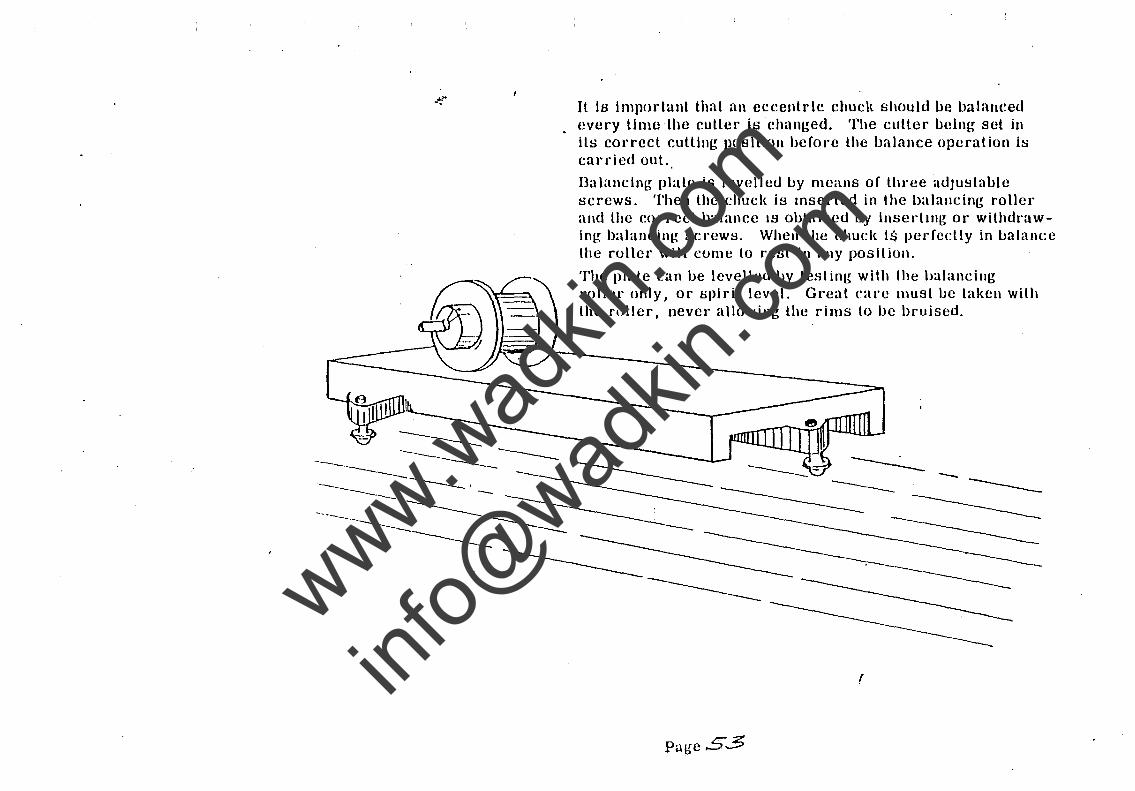
..:--. Il is important that an eccentric chucl( should be balanced . every lime the cutter is changed. The cutter being set in
ils correct cutting pOBltlon before the balance operation it; carried Ollt.
Dalancing plate is levelled by means of three adJu~table screws. Then the chucl{ is Inserted in the ha lancing roller and tile correct balance IS obtained by illsertlllg or withdrawing balancing screws. When the chucl< 1$ perfectly in balanee the roller- will cume to rest ill any position.
The plate ean be levelled by testing with Ihe halancillg roller only, or spirit level. GI·eat care must be taken with the fl)ller, never allowing the rims to be bruised.
r
Page 53
www.wad
kin.co
m
info@
wadkin
.com
11 111Il1
~ -.
11111
I £..hrUVlr L£.Ll UI' eA .lIH!.M1!. L UT':>
DOSSpH ~ 0'" "'ApU'T~ Hn'ITEP
~ 11 3 m/m
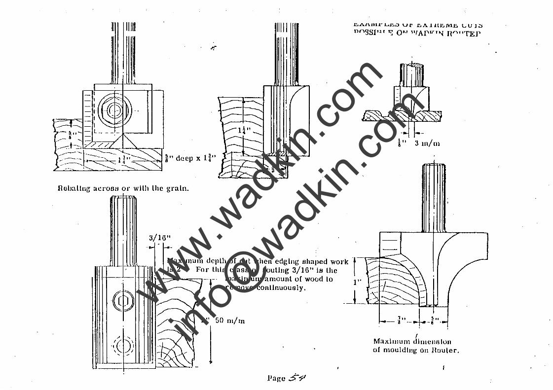
Hcuallng acrOS9 or with the grain.
J/l()1I
___ 1:_ j- r~aXlmum r- I Is 2". F
-1- - .
.~~ ~ I~ 18J " .....
~--(( )) "- ,
depLh of cut when edging shaped work -t- .,r-
or this class of routing 3/16 11 is the /' ----'-- --------1-- maximum amount of wood Lo 1 t' -----
remove conLlnuoualy. __ J_ ~ ~ ......... r--'----"-;:;...cq.!......,J
2" 50 111/ In
I 1.. I ~"
- a -+-8 -I
Maximum dimellsion of mouldillg 011 Houler.
Page S~
www.wad
kin.co
m
info@
wadkin
.com
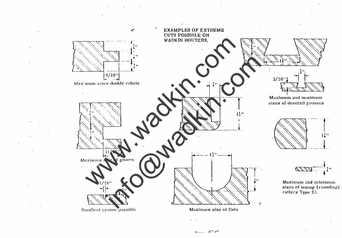
4.-. EXAMPLES OF EX'I'flEME CUTS POSSIl)LE ON WADKIN flOUTEflS.
Maximum size of f1ule
'" '.-, c-,...-
I
t"
3/1~~~~ M.lxiJllum and Illlnimulll sizes of dovetaIl grooves
_t.
Maximum and minimulU sizetl of lIosill(! (roundillld ('ullcl's Type 23.
www.wad
kin.co
m
info@
wadkin
.com
"'" -.
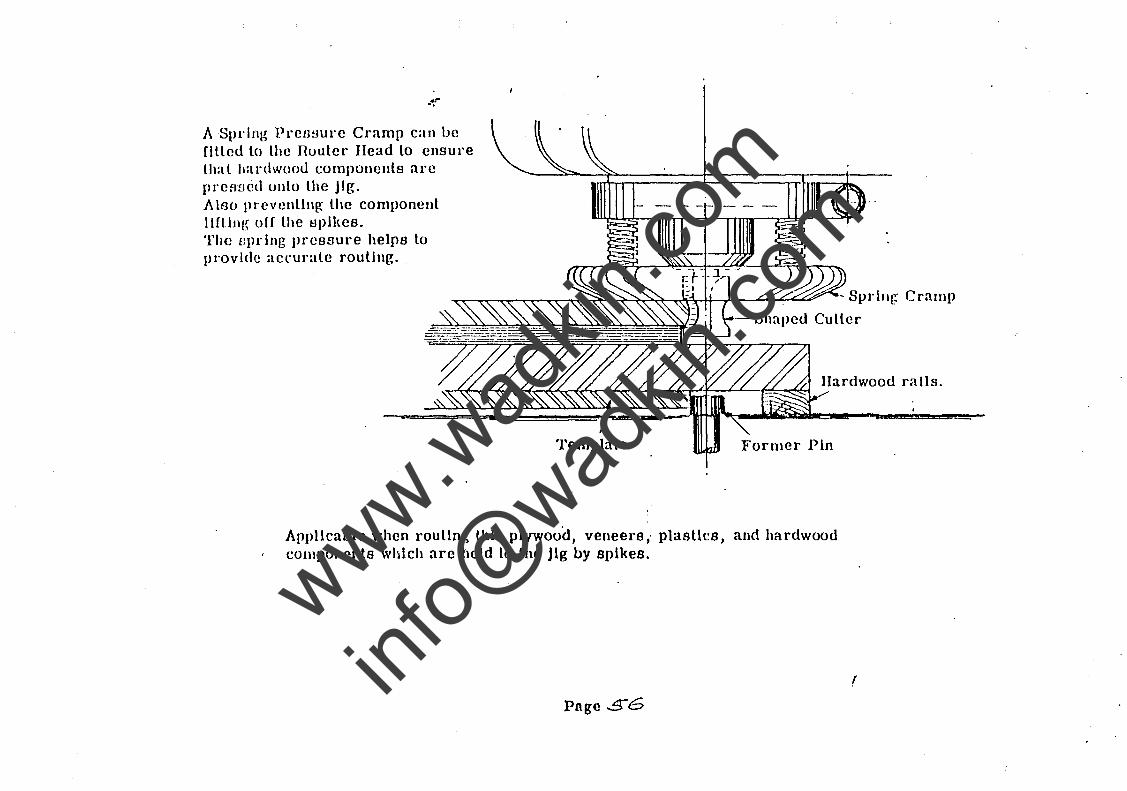
A Spring Prefwure Cramp can ue filled to lhe nouler Head lo ensure Lhal hardwood componenls are Ilrefwcd onto lhe Jig. Also prevcnllng lhe component llflllll~ off lhe spikes. The flprlng pressure helps to provIde accurale routing.
Applicable when roullng thIn plywood, veneers " plasUcs, and hardwood components whl.ch arc held lo the Jig by spikes.
Page 56
(
www.wad
kin.co
m
info@
wadkin
.com
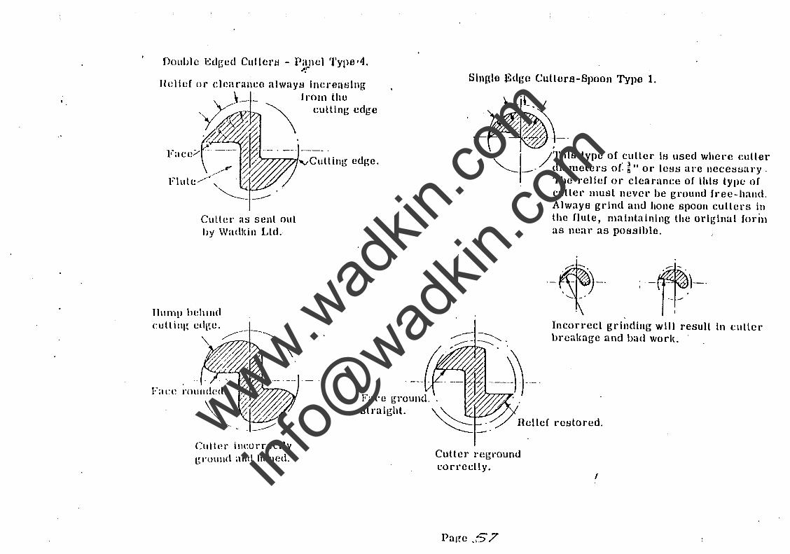
Double l':dg-ed Cultcrtl - P2JlCl Type,4, -.
Culter as sent out by Wadltin Ltd.
Culler ilH:orreclly groullci and hOlled.
culling edge
Fa('e ground. straight.
Slnglo Edge Culture-Spoon Typo 1.
. /ThIS type of cullel' Is used where cutler "-- _' diameters or: ~ It or less are nece8sul'y .
Cutter regl'ound cOITedly.
Page .,57
The relief or clearanee of this type of cutter must IlCvel' be ground free-hand. Always grind and hone spoon cutters in the flute, maintaining the original forin as near as posslhle.
Incorrect grinding will result In l:utler brealcage and bad worlL .
(
www.wad
kin.co
m
info@
wadkin
.com
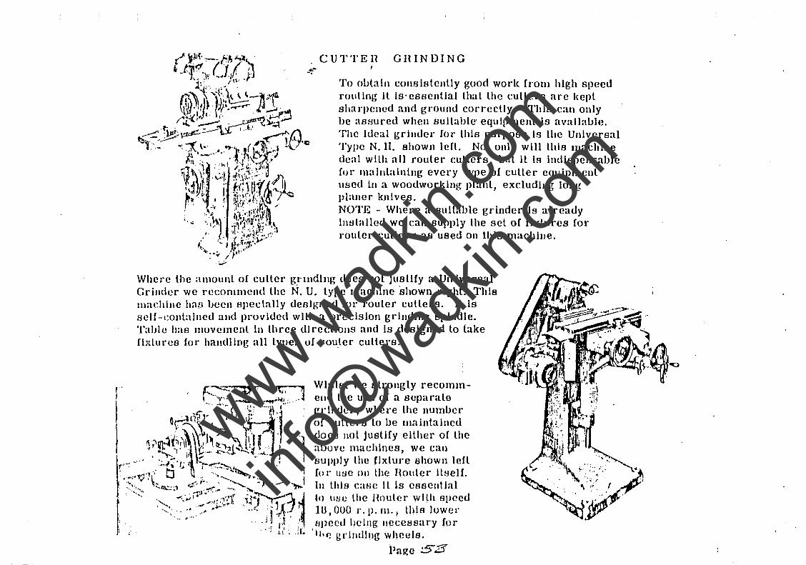
CUTTEll GHINDING
To obtain consistenlly guod work from hIgh speed routing II Is'essenllal that the cullers are kepl sharpened and ground correctly. ThIs can only be ast:lured when suitable' equlpmenl is available, The Ideal grInder (ai' thIs purpose Is the UnIversal Type N. 11. shown lefl. Nol only will this machIne deal with all route." cutlers, bul it Is indIspensable for malnlaining every lype of culler equipmenl used in a WOOdwol'klng planl, excludlllg IOllg planer knIves. NOTE - Where a suItable grinder Is already installed we ean supply the set of fixtures for rouler cutlel's as used on this machIne,
Where the alllount of cutlel' gnndIng docs not Justify a Universal Grinder we recommend the N. U. type machIne shown rIght. ThIs lIlachlne h'HI iJeen BJleclally designed fOl" router cutlers. II Is lielf-eolltalned and provided with a preciSion grInding spindle. Table has muvemenl in three directions and is desIgned lo fake fixlures fur handlIng all types uf rou,lel' cutlers.
Whilst we slrongly recommend the use of a separale gl"lnder, where the number of cullers to be maintalncd does not Jusllfy eHher of lhe abuve machines, we can supply the flxlure shown left fOI" use 011 the Houler llselL III 1I1ls C:lHC Il Is essential to use the Ilnulcr with spced In, DUO 1'. p. Ill. J lhIs luwer f:lpccd IJCillg lIecessury for
I I" ~ g rlllllJlIg wheels.
Page ;5"3
www.wad
kin.co
m
info@
wadkin
.com
~ -.
INSTIlUCTIONS Fan GRINDING WADKIN nOUTER COTTEIlS
A sharp and properly ground cU,ttcr is the key to good routing. It is important, therefore, that
the ollcrator should understand cxactly what he, is doing whcn sharpcmng cutters.
Detailed instructions in lhe grinding of all types of router cutters are given on the following
pages. and if read carefully anrllhe Instructions carrie~ out will ensure trouble frec running
and high produc:lion.
I
www.wad
kin.co
m
info@
wadkin
.com
\VOOnWOHKINa" CU'l'TEHO.
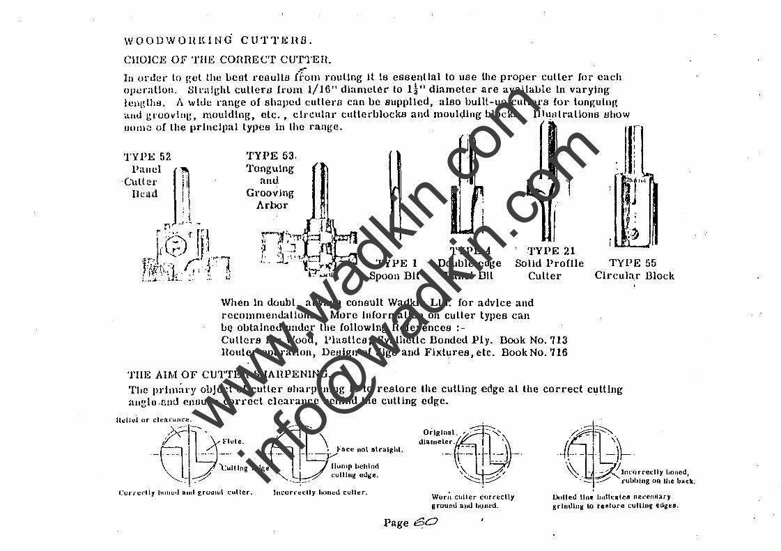
CHOICE OF TIlE connECT CUTTEH. ... -
In orJcl· lo gel the befit reaulls fi:om rouUng it Is essenllal to use the proper culler for each operallon. Sll'alr,hl cutlers from 1/1()1I diameter to H" diameter are available In varying ICIIL~thB. A wide range of shaped cutlers can be supplied, also built-up cullers for tonguing allLl groovlllg, moulding, etc., cIrcular cutlerblocks and moulding blocks. I11~tllralions l:Ihow IJOIlW of the prlnclp:ll types in the range.
TYPE 52 Pallel
'Culler Bead
TYPE 53. 'l'onguIng
anu Grooving
Arbor
r :1 i
'J I
TYPE 1 Spoon Bit
TYPE 4 Double edge
Panel Bil
. TYPE 21 Solld ProHle
Culler
When in doubt, always COJlsult Wadkin Ltd. for advIce and recommenuaLJolla. More inCormallon on culler types can Le obtained under the following References:-Cutters for Wood, Plastics, Synthetic Donded Ply, Book No. 713 Houter operallon, De81gn of Jigs and Flxlures, etc. DookNo.716
TIlE AIM OF CUTTER SIIAHPENING.
li ; ;11.1 . J f •
l~: ' .. ..
TYPE 55 Circul:~r Block
The Ilrhn:u'Y ohject of culler sharpening Is to restore the culllng edge at the correct c':!ttlng allglo .11u!.l cnuure cOl'l'ecl clearance LJChlnd the culling edge.
lIcllcl ur cll!nrllll.:e.
rr~-"""· /." .-\].-:. _ I .... ~"'.. .. . 1- .. ..J. "' .. w' .,,,,,,,,. . • . l:ullllll! Edne • • lIulllp behInd ""- .1_-:::7 "-.._. ____ - cullIng edge. . .
Curn!dl)' hUllc" nnt! r.ruulltl .:ullcr. JIICUl'I'cdl Y hOllcd cull er. Won', culler curreclly 11 round ami hOlled.
PRge~
. Dulled line IndkalclI ne,:cIIAary srllldllll!' la feature culling e(\gl!ll.
www.wad
kin.co
m
info@
wadkin
.com
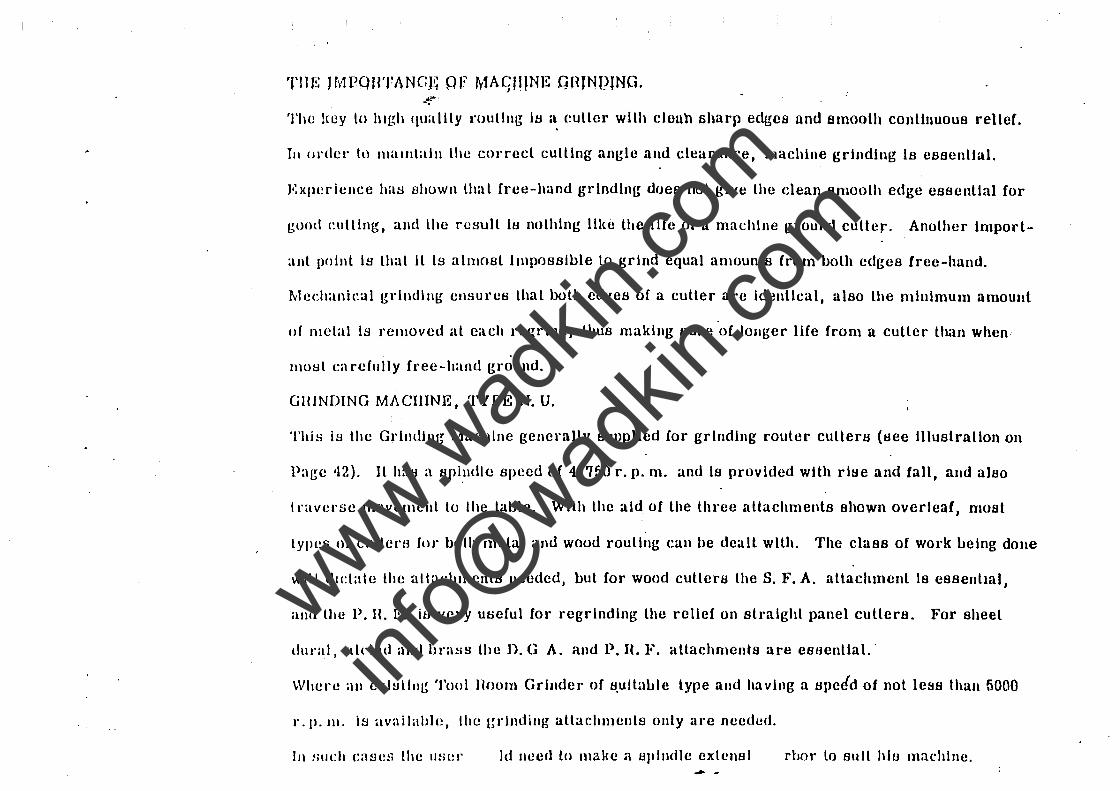
TIU!: JMPQBTANCl~ PJi' MAC,JHNE GHJNPING. ~. -.
The !tey to IlIgh quality routing lu a. cutler wllh cloun sharp edges und smooth conllnuous reller.
III or£1cl' h) H1allltaill Lhe cOI'reel culling angle and clearance, machine grinding Is essenllal.
Experience h:uJ shown LhaL free-hand grindIng does not give Lhe clean smooLh edge essenllal for
good eutllng, and Lhe rc~mlt iu noLhlng lIl(c Lhe life of a machine ground cutter. AnoLher import-
allt I)oinL is Lhat II is almosL impossible to grind equal alllounLs from boLh edges free-hand.
Mechanieal grlndillg ellsureB LhaL boLh edget! of a culler are idenllcal, also Lhe minimulll amount
of metal Is removed aL each regrind, Lhus making sure of longer life from a culler Lhan when
most careCully free-hand ground.
GHlNDING MACHINE, TYPE N. U.
Thj~ is the Grilllllng Machine generally supplled for grinding rouLer cultera (see llluatrallon on
Page '12). Il hat! a upi,lIdlc speed of 4,750 r. p. m. and is provided with rise and fall, and also
traverse movelllenL Lo Ihe Lable. With Lhe aid of Lhe Lhree attachments shown overleaf, moat
types of cullerH Cl)!' both meLal and wood rouling can be deall wllh. The class of work being done
will dictate the altachments needed, but for wood cutlers Lhe S. F. A. attachment is essenLml,
alld the P. n. F. iB very useful for regrlnding Lhe relief on sLraighL panel cullers. For sheeL
dtll"al, aldad and hra~s the n. G A. and P. H. F. attachments are eBsential.·
Where all exl~lIl1~ Tool Boom Grinder of B,ultable type and having a Bpeid of not less than 5000
r -11- II\' is availahle, the grlndillg allachmenLs only are needed.
III sllch ca~J(!!1 lhe IISI!l- Id need to l1lake a sJllndle cxtcllBI rbor to Bull his machine_ --
www.wad
kin.co
m
info@
wadkin
.com
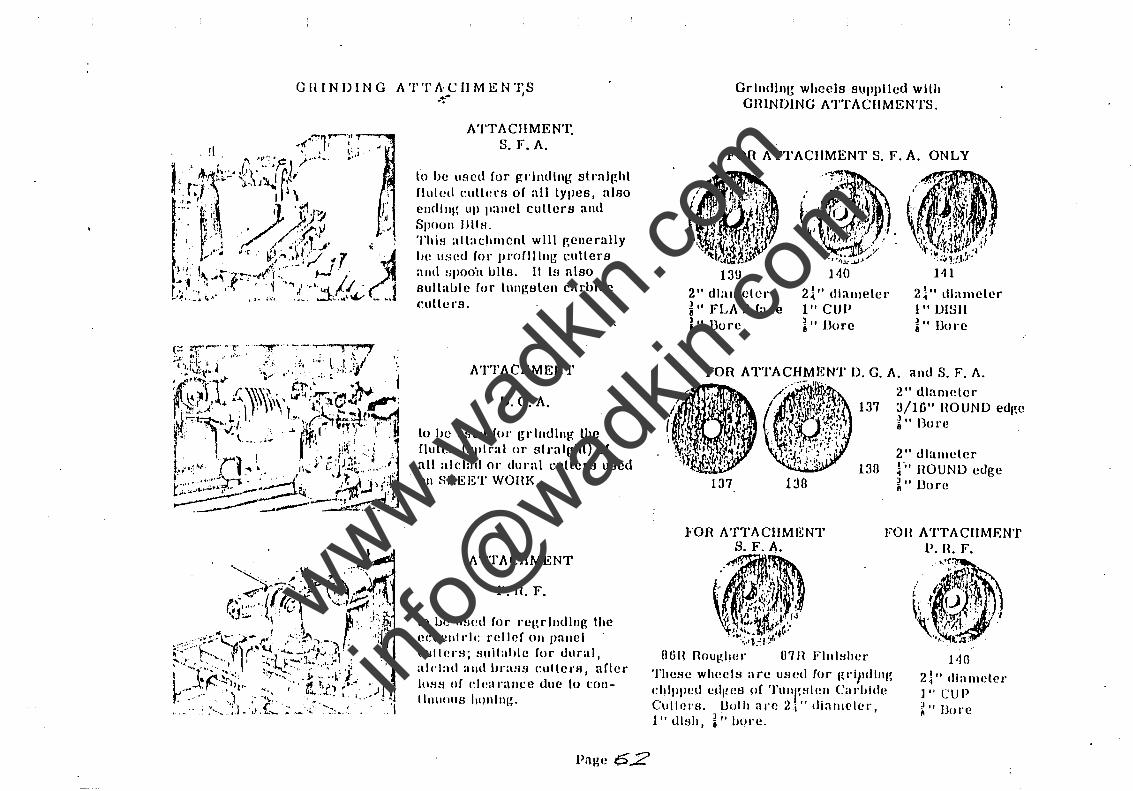
CHINDING ATTACHMENTS ~ I -.
ATTACIIMEN'l: S.F.A.
to be used for gl'illlling stnllght fluted cullelOs of all types, also endlllg up pallel cullers anll SpOOII BlIHo 'flliH allachmenl will r,enerally be IIsed for IJlooflltng cutters and spooh bllso 11 IH also sullalJle for tlln~8lell carbide (~lIlte ra 0
ATTACHMENT
D.G.A.
lo he used fOl o gdlldlng the fluletl (spiral or slaoalghl) of all alcl;ul 01 0 dllnll cullers used 011 SHEET WOIIK 0
ATTACHMENT
P. H. F.
In lw mwd for loer,rlndlnr, the eecenll"lc relief on panel cullen:l; slIilahle fur dllral, all-lad and iJraH8 cullers I after IO!-l!-l of de;lI°:\nce dlle 10 (:011-tlllllOIlS honlngo
Pa~e 62
Or Indlng wheels supplled wllh OIUNDINO ATTACIIMENTS.
FOR ATTACHMENT S. F. A. ONLY
2" dlalllelelo ~" FLAT (ace l" Dure
140
2l" diamelelo
l"CUP ~" Bore
137
130 1:.10
111
2l" dlamcter 1" DISII 1" Bore
2" dlaowter 3/1u" HOUND edge ~" Bore
2" dlallleter p. HOUND edge ~ .. Uorc .
FOR ATTACHMENT S. Fo A.
Fon ATTACHMENT P. H. F.
OGU Roug:lwlo
These wheels arc used ((11· Itri)ldllll~
chl11lWd cdges o( ')'Ullrstell Carbide Cullerso Dolh aloe 2i" diallleter, 1" dl8h, ~"hureo
1'16 2!" (lIametclo
] .. CUP ~ .. Bore
www.wad
kin.co
m
info@
wadkin
.com
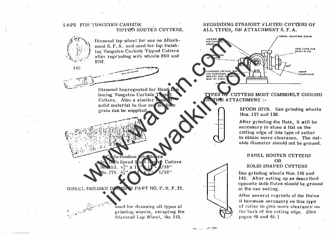
LAPS Fon TUNGSTEN CAflUIDE I
TIPPE'f) HOUTEH CUTTEHS.
Diamond lap wheel (CU' lIse on ACtachmellL S. F. A. and uscd for lap finlshinl~ 'l'ung-titcn Caruidc Tipped Cullers aHer reg-rlnding- wilh whcelB OGIl and unc.
Dia mond Impregnatcd Co r Hand Lap honing Tungstcn Carhide Tipped C\lller~. AI~o a similar hone of solid material In fine and medium gl'aiu can be BuppIlcd.
\VIIE~:L DHES!.iEH DIAMOND.PAUT NO. P. n. F. 37.
,'" . ., ...... ::J:i:,·· .' !' .';' " .. ,
. " .. t.. .~, ;,';-~,
Iwcd fOl' dl'etl~illg all IYPCB of I~rlndlllg whct!ltl, Cxcul1ling Ihe Diamond Lap Whec 1, No. 1-15.
REGIUNDlNG STIlAIGIlT fLUTED CUTTERS OF ALL TYPES, ON ATTACHMENT S. F. A.
IOUIt-IG BOLT fOR (AtlIING A160~
t'MAX. ROM or (11lICI(
AAOI"L "OluSlIt-IG SCREW
sro~ I(VU 101 INO[X'I"H
~: COHhll·IlD lOCl<IIjG aOl r rOk SWIVLLlING "kBO" .--
f l ___ "IBOR
.-::;-- "A/mWII! Cl. bRALH r Aun HCURltlG IME lO r"hlt
TYPES OF CUTTEHS MOST COMMONLY GHOUND ON TIllS A'fTACIIMEN1f :-
r ----4
I .- ._,-' . - - ~
I I
"
SPOON DITS. Usc gl'lnding wheels Nos. 137 and 138.
After grinding ;the flute I it will ue necessary lo stonc a flat on the cutting cdge oC this typc of cutter to outain rnol'c clearance. The outside diameter Bhould not be ground.
PANEL nOUTEfl CUTTEflS on
SOL.JO SHAPED CUTTEHS
Use grinding wheels Nos. 140 and 141. Alter Bclling up "6 descrllJed oppoulle both flutes Bhould be ~roulld al thc one Bctting .
After fwvcl'al rccl'lnd~ of the flulcu II hC{;()1l1cS ncecstlary on Ihl~ type of cutler 10 give llIore clearance 011
lh e badt of lh e cull ing ed~e. (Sec llag(!~ 40 and 4U. )
www.wad
kin.co
m
info@
wadkin
.com
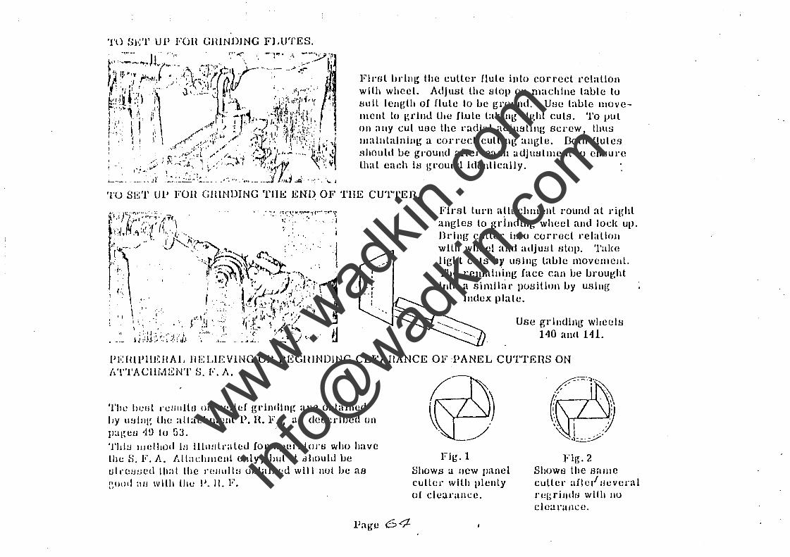
Fiml bl'lll~ the culler flute into correct relalloll with wheel. Adjusl the stop Oil machine table tu l:lllll length of flule tu ue ground, Use taule llloveBleuL tu grinu Lhe fl.ule takiug light euts, To put on allY cut uue lhe l'udlal adjul:ll1nl~ screw, thus lllaintainillg a corred CUlling allgle, Doth flutes should be gl'ounu aflel' each udjutJtlllcnl lo ensure lhat each is ground idenllcally,
Firsl turn aLtllchlllent round at ril~hl angles to grindillg wheel ami lock up, Bdllg culler' iuto COITOcL l'clalloll with whcel alld adjust ulop, Talw light cuts by usillg laule movemcul. The l'elllaill\ng face can ue uroul!,ht illlo a similar pOtJillon uy utJllIg
Index plale,
Use grllldlllg wheels 140 nnLl 141.
Pli:lIlPIIEIIAL HELlEVING on HEGUINDiNG CLEAHANCE OF :PANEL CUTTEHS ON
'nil! hcut J"emdtu on ,'clle! grlndinl~ are oLtaillud by lIUillg the allachmcut P. n. F. , aB deecdued Oil
]) age u '1!} I () ~:3,
'fhl!.] l1Ielllod it! llhllJtralcd fol' 0llol'nloJ's who have the S, F. A, AllaeilJllenl (July, but 1l dlaould be Ull'Olwcd Ihal the re/llIltH ulJtallleu will 1101 be aa glILH) :IIJ \Vllh lhe P. 11. F.
Flg.l
Shows a new IJ:l11el cutlet' wllh plenty of cie:).r:lIIl:c,
Fil~. 2 Shows lhe sallle culler afle/ Iwvera I J'egrlJ1du with nu cleanlllcc,
www.wad
kin.co
m
info@
wadkin
.com
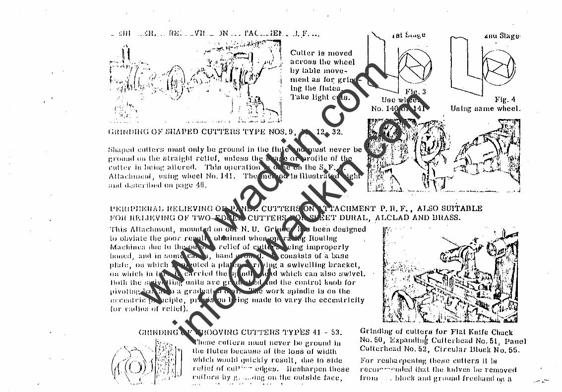
GlllNlllHG OF tJIl.J\pgO CUTTEnS TYPE NOS.!), 11, 12, 32.
::illilJll:d cullers nlllHL only lw groulld in the fluLe and lllUHl Jlever be gnlll:ll! UII lhe oLnlieht I'clld, ullle~w the Hhape or profile of Lhe cutll!\" hi J)(!illlr, allered. Thiu operation is dOlle on Lhe S. F. A,
Atlac11llwnl, lISilll~ wheel No. 1'11. The'meLhod IH llluol1'aLed right illlll d.~:; Cl' illl:d Oil ll;lI~e -1 n.
Flg.3 Uoc wheel
No, 140 or 141
L.IIU Shlge·
Fig. 4 UsllIg Bame wheel.
. PI':ltlPI:I':llAJ.. HIU.IE:VING OF P.J\NEL CUTTEIW ON ATTACHMENT P. n. F., ALSO SUlTABLE VOU 1I1!;l.lI';VING OF TWO-EDGED CUT'l'EIW FOH SHEET DUHAL, ~LCLAD AND llHASS.
This AllachllwlIL, llHHIIILed Oil ollr N. U. Gl"illdel' has bee'n deBlgned Lll ol;viaLe Lhe pOOl' reBuilt; ubtained when operating HouLlllg Machiue:; lill(! 10 lhe (JuL!Jlde rclief of cuLLers l.lCiJlg impropedy llIllI!!:!, alll\ ill tWllIC Ciltietl, halld grolllltl. It cOlIsI.tlLs of'a uaHe
plait:, Oil which i~ l)ivoLed a platell earryllll{ a Bwlvellillg LJl'acket, Oil which ill IUt'1I in carded Ihe tlIlilldle head which can alBo t:lwlvel. /loth LlH! tn'/ivc!llillg UllillJ are graduated alld Lhe conLrol IUlou (01'
piv()linp. has ;ll!m a graduated dial. The wOI'k Bpindle is on Lhe C!('cl:illl"ic; pl"illeiIlle, provisioll being Illade Lo Vill'y thc eccclltrlcJly (01' \'atliu:-J of relief).
GIIlNIHNG OF GHOQVmG CllTTEHS TYPES 41 - 53. Thelle cullCl'H 1I1utJL IIcvel' he gl'oulul III lhe fluLCH hCC"lltH! of Lhe lous of width which would quieldy re~II11, due to aide relid of l:ul""-- {!dl~ct:l. nCtJhal'llClI lhcse 1'1"1':1'11 hy g .... jill(~ on thc OUIHldc face,
Gl'lncUlIg ot cuLLerB tor FlaL KI1JCe Chuck No. 50 J :U:xpalldlllg Cullerhead No. 51, Pane] CuHerhead No. 52, Circular Block No. 55.
For rCl:lhaqlenlllg lllcHe eutterB II la rccoP'~~"lIded thaL lhl! ItIIlvctJ Jw rcmoved (1'0111 • 1>lod( alld gTlllllHI freehand OH a ,.- ... :--
www.wad
kin.co
m
info@
wadkin
.com
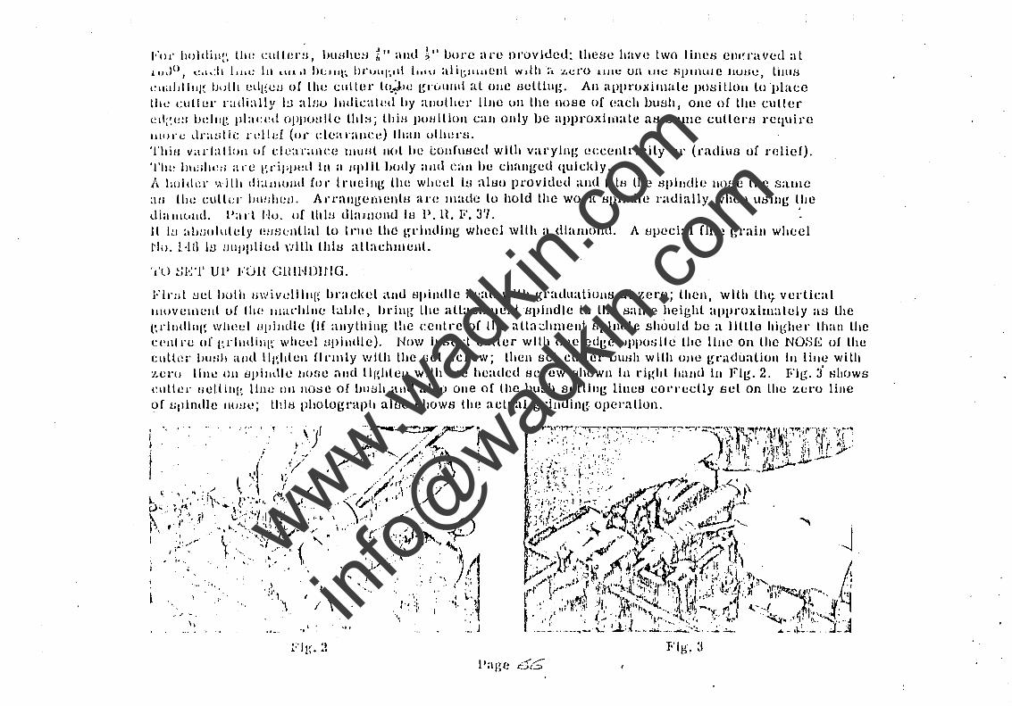
I,'Of hl)ldill~', 1Il(~ cull.el':J, lHlHheH ~" aud ~"!Jure al'e Dl'ovlded: theHe have two lillCD cllI'raved al llJ\)O, e.,,:1l 1.111: 111 l\11.1 IH;llIl; hr'H'I, •• ll IlllU alil;llllleul wdh :. :1.1.:1'0 11111.: on IIIC 61JlIHlle llUt:lC, lilllH Cilililllllg lwlll l!dgelJ of the t;lI11er Llt~4le gnJllIlI1 al OBC tJelllul{. Au approximate J)o611lon IOlllaee 1I11! culler radi:1l1y I~J alt;u 11l(lkaLeti by anuther lllle UIl the !lOBe of each 1)\19h, one of the culler ed;~(!:1 IJdllg Jllac(~d 0Pilutllle lhl:i; lldB poullioll call ollly ue approximale UtJ Bume culleru rC1luire Illt)J"c dr:wtle rdld (t,,· dearallc(~) Ihall othl!nL 'i'hilJ V;II"Iallull uf clearance IlI11Hl IIcll be l;ollflltled wllh varying eecenlricily or (radius of relief), 'I'll:! IHI!lhe:1 are l~l"iJiJll!d III a Hplll body alld eau be changed Ilulcldy. A hold,! .. I,dlh diaulullll for lrl1cillg the wheel It.! all:lo provided alld fllt:l the tJpllldle Hose the same :\0 till! culler bll!;II1!LI. An'ullgelllentB are JIlade lo hold thc wode upindle rauially when using llle dia 1I11.111tl. Pa 1"l Hu. of thin dl:ullolld lu 11. H. F. 3'T. . II 11.1 ablJoluldy I!II!H:nUal to Lnw the grlndlug whecl wUIt Cl diamond. A upecial flue graill wheel Hi). 1-1 ti ID LJ IIJlP 1 i et! \'J llh t 11 16 all:tchlll ent.
','U ~jl'~'l' UP FUll GHIHDIlIG.
Flrlit tiel bulh /jwivdllll(~ hracket anu H\lindle head wllh gradualionB at zero; lhen, with lh(j. verllcal 1I1UVellH!lll of Ihe IlIilcilllle L;1Lllc, hrilll~ the aUachmenl Bplndle lo the same heighl approximalely as lhe erllldl/lg Wlll~el llpilldle (If al1ythilll~ tile cellll'e of the alla~hlllellt flJ)llldlc should vc a Illllo higher thall lhe centre of grllltling wheel !lpilldle). Now Il1BCd culler wllh olle edge opposite lhe lllle On the NOSE of lhe elllll!r blWh and IIghtell flL'mly with tile fiet screw; lhen sel cullel' !JuHh with olle gt'adualioll III lille wilh 'l.Cl'O lllle Oil tlpllltlle Ilone and L11~hlcll with lee headed I:Icrew shown In right Iialld ill Fig. 2, Fjl~. J' Hhows 1~llllel" Ilellillg lIlIe Oil Hose of hlli::lh alld altw olle of the uush selling linea cOITedly sel on the zero liue of l..illlndle 1I11!JC; lhll:l photograph aluo shows the actual grilluing. operallon,
Page
www.wad
kin.co
m
info@
wadkin
.com
11 will Iild 1)0 IICnlilll;)I'Y ilU~l gellural rulo 10 Jl\OVll Iho Hpllldle head away (I'um zuro, bul the Bwlvelllnl! Ilrachd (whkh hiW lIu )lilli-e Oil IIII! plateJl) will require lHovlllg a little off ~cro fill' Ihe Hplrill fluted cllllerH, IllherwiIH1 dll(: to tht! liplrill all~le, ,the grllldln(~ ()llCl'athlll will produee tl taper cutter.
10'411' .-it!,ld hand :ipll'al cullenl IlHI\'l! the bracket zero IIl1e a lItUe to Ihe IcLl and vice vel'sa for left halld ~ipil'al 1'11111:1", Fil';. 'I ullo\'/::J Ihe 'l;l!l'O lille un ul'aelcel moved ouL of line ilH required rOI' a right halld tj!l h';1I (:\1 tit.: 1".
TO CIl H'W A Cl/'fTEH.
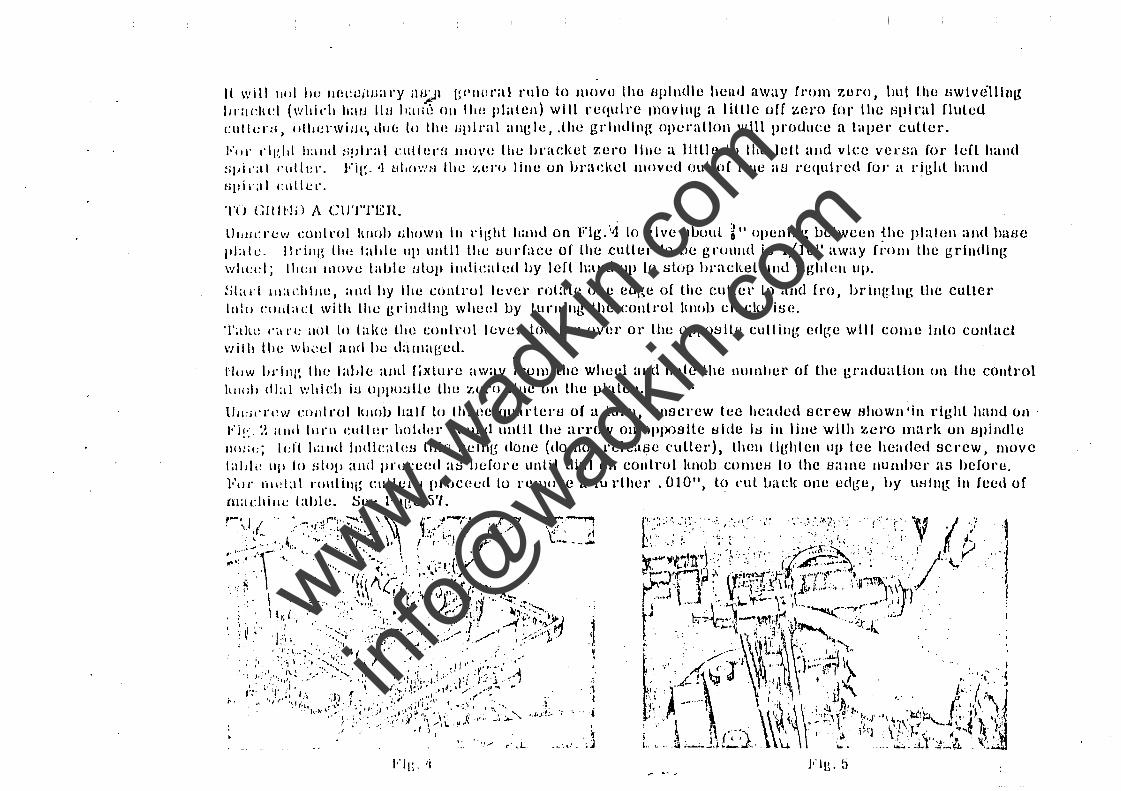
LJlllICreVJ nHltrol hllllh "hoWI\ III right balld on Fig.'·Ji to give ~II.)l)ul ~" opening beLween {he platclI aJld hiwe pble, llring thl! lable lllllllllll tile tJurfaec of lhe culler to be gruulld iB 1/]u" away ri'olll Lhe grinding wheel; 111(:11 1l1OVI! laljle tJlup illdkaled by left halld lIJl 10 ~top bracket ilml lighlt~1I up.
~jlad lIIadlllle, illId lIy Ihe cOllll'ol level' rotate one edl~e of Lhe euller to aJld fro, brill(~llll~ the culler 11110 Cllttlat:l wilh the gl'illdllll~ whed IJY turllillg the cOlltl'ol IlIIob cloc\{wiBe.
'I';llw I'~I re lIoL 10 lalw Ul(~ conlrol lever too far ovl~r or Ihe opposite cuttillg ec1l~e will come luto cOlllact \'Jilil lite \Vh~:cl and be t1aclI;qsed.
/"IlIW 1)J'i11{~ Ihe lable amI fixture away from Lhe wheel alld note the Illllnhel' of the graduation un Lhe couLrol hllo\l dial wldch iLl oPl'o:Jlle the zel'O lille OH the platell.
llU:jl'I'I~w conlrol Illlob half to three CJuarlertJ of a turn, un:Jcrew tee headed serew Hhowll'in righL hand on . l'i!'.-:~ illId IIlnl ellllel' \toldel' J'{HllHl lllllil the arrow on OIlPosile Bide IB in line with zel'O lJIarl~ on Bpindle IIO:;\:; Idt I.aud IlIdleatc!B this \Jeill~ clone (do not release ('ulled, thell t1~hleu lip Lee headed screw, IlIove laid,! up 10 slop and proceed :lti lJef(Jl'e unlil dial on cOlltrol Itnob COllleH 10 the Billlle numher as before. Foe rlll!l:l1 r()lItilll~ clIllel't.J proceed 10 remove a fll l'ther ,010 11
, to l'lItIJal:l{ one cdge, by using III feed of ma chille lable. Sce Page 5'1.
www.wad
kin.co
m
info@
wadkin
.com
1'\11' ,:Ilt!I:I':; of l:rcatcl' leJluth th:II~,.tlll~ f:ll:e of the wheel, rel)cal the opcratioll with Lhe Lable Cl'OHH l1'aV(!I'jJe adJ\I:lIL!d III cOver the rei'nalllllll~ lenglh of lhe cuLlel' etl(~e, When flnitlhlllg, paHB lhe culler ()v!!r Lhe gJ'indllJ:~ ':!heel once (H' lwice, l1l(JVllll~ the (!I'OSB Ll'avert>e Hlld(! lI11ffldcnlly lo cover Lhe ~JL!;[u 1~!II,:UI ui' I:l!: cllILlII:~ edge lH!illg J'ellevcd. On uhorl cullel'tl move the lTUBtJ lraVel'He Cl lHUe each \'::\y tu lLl'~H'ov:l llli.! Iludaee fllllLlll.
l"li~. ~ tJl HI\': 11 llm! !he (ll:~(!lIll'ldly (OJ' J'adlulJ uf relief) It] vadetl. 'l'b;! /J~}ill(ll~: II'J~J,! k,tJ all lul11al aUlounl of (l1:CCllll'lclLy which can lw varied au followt-J :.,
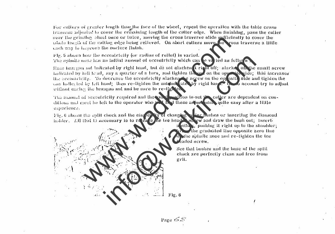
l':'~l;;l la~lll;"i~()1I Hut Illdll:alcd l)y fighl hand, bul tit) nol BlackcII Il rlghl off; Blaeken off the U111all fJC!'(!W
itldl,::li(!d Ily ll!li I';'lld, /lay a quad!!!' of a lllnl, :tllllllghlcll the one 011 the uI)pualLe Hide; lhllj Inct'cases lL~ ~:CCUHi fklly, 'l'iJ deel'e:l~w tlle ecceJllrlclly Hlaclten lhc t1CJ'ew Oil the oPl)o8iLe Hldc awl lightell Lhe {,li!: 11l.!lc.,l;:lt JJ~' ldl h:ulll; Lhell 1'e-Ughlell Lhe nlll IlIdlcaled l.Jy 1'l~hl ltalld. 011 IIU aceuunl lry lo adJlli.ll \'!il!Hllll {!;~dlj:~ llll! h(!J{agoll Bill nud In! 1Il1l'£! lo re-lll!.hlcll.
Tt .. ! itlslllllllt of ::(:c;:lIldelly t't:qlllred and lhe e:xacL potdllun lO'Hel the cutLer are depelldenl 011 CUIl
dilldHi; all;! I::i~d ll~ lell lu the 0IJCl'alol' who will Hnd lheoc adjuf:lllHeIlLf:l quiLe easy aflcl' a llLUe v;;ll:!deJlc~.
I"it~, (j Ulllr.Vtl th~! d~illl CJ.Udl and the 1I1Illplldly uf chan~lllg ellLLcr IJu!:Ihes or intJerllng Lhe diamond l1~jldl!1'. 1.11 Ibal !;! W!CClw:u'y iu lo l'ele:wH the lee headed screw alld draw the IHWh oul; !JIBed:
..'
"I.'. , ,"
allolher, l)lIfihllll~ II l'lgh-L up lo the tlhouldcl'; I.Jd IIg lhe ~l'adllaled lllll! (1)poHlle zero lllle on lhe BiJllldie nOfJe allli l'e-ti[!;hLell the Lee headed tlCl'CW •
See Lha~ IHwhef:l alld chuek are pedecLJy gl"lL.
Fig. 0
lhe base of lhe HpliL clean alld free froll1
!
www.wad
kin.co
m
info@
wadkin
.com
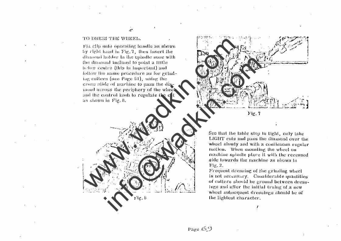
.. --. TO 1) 111': ~.;~j TilE \V 11 E I': I..
ti'i I~ clip ol\Lt> OIH!rillillg halldle au ullowlI by j"il~ld h;llld ill Fig. ", 1l1l!1I iJlserL Lhe diillllllllll hllldi:l' 111 thl! t.;pilidlt~ nose wlLh {Ill! tli:illllllld illl:iilled to \loilll. a llltle 11,:1,,','/ celll,',! (thi!l i~1 ItllplJl"I:tIlL) alld [011.1\'/ 11\(: tlilllll! pnie(~dllre iltl {or gl'illdLII'; clIlII!rH (S(!t! P;'l~e !i 1). lI:Jilll~ Ihl! t: I'll:; IJ !l1 i d t~ tI f III a !'I1i 11 t! l u pas s I1 w d i a -111111111 i\l:I'()!jH lilt! 1'(!riphery of Ihe wheel and Illl! clllllrol Iwull 10 regulale lhe cut ;In 1;110WII ill Fig, U,
'. ;',' ,.' . ;-;~ :".
Fig. '1
See IhaL Ihe Lable olop it! lIghL, only lake LIGllT euls alld patHJ the dlalllOllll Over Lhe wheel tJlowly and wll.h a cOlliillUOUH l'egular Hill I iOll, Whell moulli IlIl~ lhe wheel Oil
machille 6pilldle place it wlllt Lhe reeellBed side IOWill'dl::i Ihe lllil/:hille iH.I fJhoWIl iJl FiL{, l!, Frequent dre:wiJ1tr of .tlll! grilldiIli~ wheel iH lIot II(!Cet-ifl:ll'y, COlliJlder:li)le (JII:lJlLilietJ of cullertl t.lllollld lie gn)ulIll belween dn!su-111(~S and aflel' Ihe inillal lnlill({ of.a lIew
wllee I tillb~1 equ ellt dl"(!tltlill~tJ lihoul d be of Lhe lighLc:J1 dlaraeter.
(
Page .63
www.wad
kin.co
m
info@
wadkin
.com
'~'j'O 1\1 11'-1 (~ f) F r U '1"1' I~ n I~
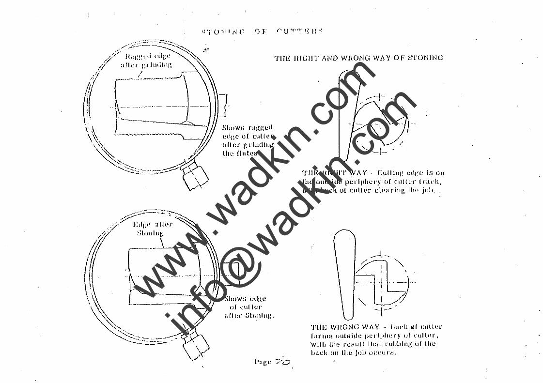
TilE HiGIlT AND WHONG W A. Y OF ~TONING
tJltuW6 nlgged edl~e of culler aller I~ l'illdillg till! flules.
SllllWS edge of clIller
aller Slol\illl~.
. Paec -;'-"0
TilE HiGH'!' WA Y - Cutti1lg edl~e is 011
tile oUlside periphery of cllller ll'ack, wlLh uaek of ellllcr clearllll~ lhe jol}.
TIlE WIIONG WA.Y - Jladll{lf culler flll"lllB ulll6idt~ periphery (Jf ("ullt!r, 'WHit Uti! rC!jllll lltal rubbIng of lhe LJat.:ll 011 the jou OeCUI"/L
www.wad
kin.co
m
info@
wadkin
.com
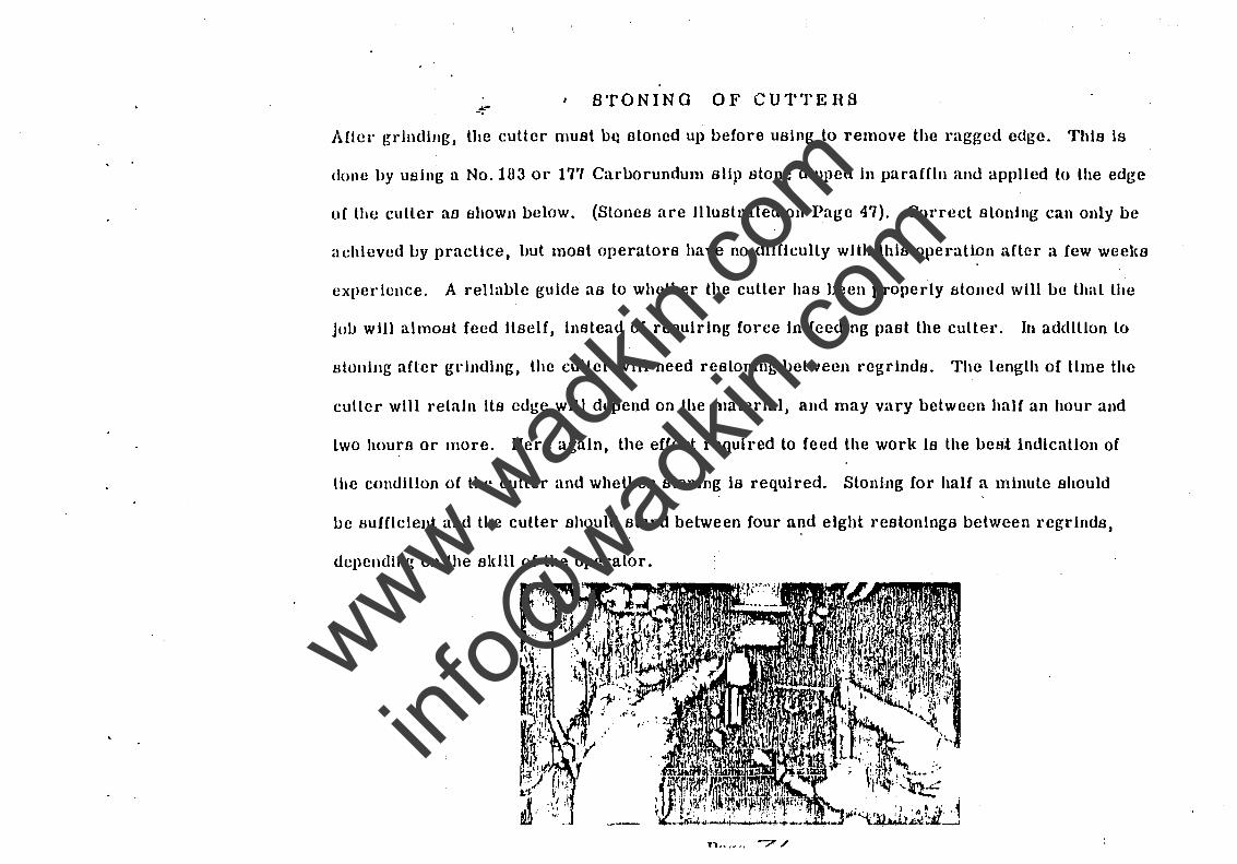
- STONING OF CUTTERS -. After grinding, lhe cutter must uQ stoned up before using lo remove the ragged edge. This is
done by usiug a No. Hl3 or 17'/ Carborundum slip slone dipped in paraffin and applied lo lhe edge
of the culler aB shown below. (Stones are lllustrated 011 Page 47). Correct sloning can only be
achieved lJy practice, hut most operalors have no difficulty wHh this operatiDn after a few weel{s
experience. A reliable guide as to whelher the culler has been properly sloned will be lhal lhe
job will almotJt feed llBelf, instcad of rcquiring force In fecding past lhe cutter. In addillon lo
stoning after grinding, lhe cutter will need rcsloning between rcgrinds. The length of time the
culler will relaln lls edge will depcnd on the malerial, and may vary belween half an hour and
lwo hours or more. lIere again, the effort required to feed lhe work Is the best Indicallon of
the condition oC the cutler and whelher stoning is required. Slonlng for half a minule should
be sufficleJlt and the cutter should stand between four a~d eight restonings belween regrinds,
depending on the skill of the operator.
www.wad
kin.co
m
info@
wadkin
.com
T Y pI (" 1\ L (lll ES'/'I()t\JS . /I 10,,) A lI.'C!UJ E p~ '1N UJn0D un UTr.·n CU<I"r'r~n C'II '\ n p r,>"IIN ('
. , Is a ~'lItter as de~;Jlalched by th~'llakers ready for use?
No. II I'equircs honllll~ or stonill~ before being psed. The cullers are sent out as they leave lhe Grindin(! Machinc. They ~I'e not slolled up at our Works as the edge may be damaged In lransit.
Is the lIse of a slip slone necessary on rouler cullers?
Ycs. All cullen, shuuld be honed before using on the flouler. The sharper the culler the better lhe finIsh and Ihe faslet' Ihe feed.
What sod uf sI ip slolle should be used, and what methods should be employed?
See reeOIllJlHHlI at\olls as rer~ards slones on Page 47, and the method of stonIng, Pages 54-55.
How often should the culler be honed? ,
This dl'Pf~lIds on the limber l)Cinf~ cul. Sll'lngy limber may require a stone on the culler every 20 minutes, while on clean straIghl grain. wood the culler may run for an hour.
When does a culler need sharpening?
When the work Is difficult lo push past the cutter, or when the flnlsh is not clean and smooth,; the two characlerlsllcs generally go logelhel·. When the culler Is sharp, the work wlll almost feed Itself.
Wha 1 dctCl'IlIllIes whelher a panel culler should be ground In the f1ule or on the I'ellef?
The l~encl'al practice is to ~rilld In the flule, as shown on Page 40, and conllnue lo do so unlil the n~llcf ur clearance, shown on Page 44, becomes insuffIclent. Then regl'Ind tlie relief as fihown Oil Par~es 4U to 52.
Is lhcl'c allY lIIeallS of It'ulllg the emery wheels on the Culler Grinder? Yes. The dlalllol\d mounted In it steel holder, 4" dlameler, is shown on Page 47. The method rOl' I ruin!! wheel No. 1-10 Is shown on Page 53. When truing the face of the wheel No. 141, mount Ihl' diamond ill place of the cutler on the atlachmenl S. F. A. shown centre of Page 48, alld fH'oceed as dpRC l'ilJed Oil Page 53.
Is machille (~rlndiJ\g of cullers essenllal? (
y(~s. Tt) v.ct ~ood work, and economy of cutter life. See Page 45.
Pnge 7.2
www.wad
kin.co
m
info@
wadkin
.com
. ,
nOUTI!;J( (;UTTI!:HS FOR NON-fEHROUS METALS. I
4!" -. CUTTEHS Fon NON-F~~nnous SHEETS.
Wadllin cultel'S are made In two ranges, one having a profile suitable for cutting Dural and Brass, and the olher suitahle for culling Aluminium and Aldad. In general, these cullers are quite suitable {or use as senl out,· without modifjcation of the profile, but some operators claim to obtain improved pe..cormance by sll(~htly 1lI0difylng the Ill·ofHe of the cutter to suit the particular specification of metal which they are culling.
These modifications may he regarded as refinements and should not be allempted until the operator has beeome quite proficient in the use of the machine.
The I ypes of cullers availahle are shown on a list which Is isslled and revised from lime to lime, and can Lw ohtained on enquiry from us. All Wadkin cutters are numbered and it Is advisable to quote the reference Ilumber when ordering or referring to specific types and sizes of cutters.
For ClIlI illl~ out from sheet the hest size to use is a ~ It diameter double-edged cutter, having a ~" diameter shanll. It is possilJle to use a 1" culler where k" Internal radii are essential or ~" diameter, if required.
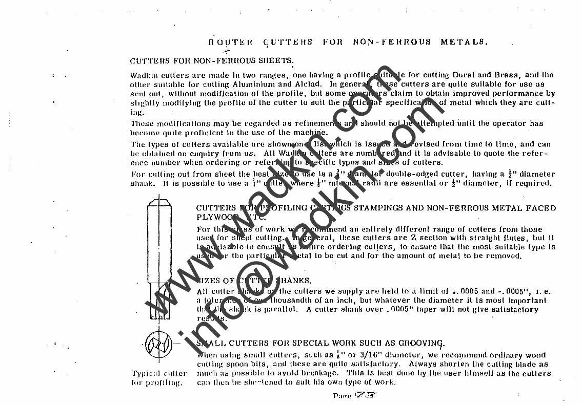
TYJl ica I clIller fo,· pr()fi1ill!~.
CUTTERS FOR PROFILING CASTINGS STAMPINGS AND NON-FERROUS METAL FACED PLYWOOD, ETC.
For this class of work we recomm~nd an entirely different range Of cutlers from those used for sheet eulling. In general, these cullers are Z section with straight flutes, but it is advisable· to consult us before ordering cut~ersJ to ensure that the most suitable type is used for the pa rticular metal to be cut and for the amount of metal to be removed.
SIZES OF CUTTEH SHANKS. All cutter shanks on the cutters we supply are held to a limit of +.0005 and -.0005" J i. e. a tolerance o( one lhousandlh of an inch, but whalever the diameter it is most important lhal the shanl{ is pa,·allel. A culler shank over. 0005" taper will not rrlve satisfactory results.
SMA LL CUTTERS FOH SPECIAL WORK SUCH AS aROOV1N9 .
Nhen usin~ small cullers, such as 1" or 3/10" dlameler, we'reco~mnend ordinary wood clltlin~ spoon bits, and these are qulle snUsfadory. Always shortQn the CUlling IJlllde as much as possible lo avoid breakage. This is best done by lhe user hlmself as the cutters eau then he sill' -jened to sull his own type of work.
P:tI~P. '73
www.wad
kin.co
m
info@
wadkin
.com
JlOW TO TELL WHEN A METAL WOHKING CUTTER NEEDS nE-GmNDING.
The first thing a f"f tiling machine orH~~;ator should know Is how to tell when the culler Is sharp and working correctly. The answer Is that when the cutler Is right, the chips will leave the culler bright and cudy, and the feed will he so easy that the Job almost feeds llseH. When these conditions exist the culler will have a 10llg life between gl"illds.
U the culler Is Illcorr"ect Iy ground, the chips wlll come ocr In straight shreds, and an excessive amount of force will be needed to.llush tile job past the cullel·. Good work Is out of the question under such conditions, and there Is always the danger of pushing the end oH the culler. If the culler is not working correctly, stop the machine Immediately and find out why.
To ensure Ihe maximum life of the culler, and at the same lime obtain free culling, It Is essellllal that Ihe culler Is kept eHlclently lubricated. Always use a lubricant conslsllng o( it mixture of paraffin and lal"d 011. The simplest method of application is by brushing the lubricant on to each blank before clamping. The lubricant need only be applied on the sheets In the track of the culler.
THE IMPORTANCE OF MACIIJNE GRINDING.
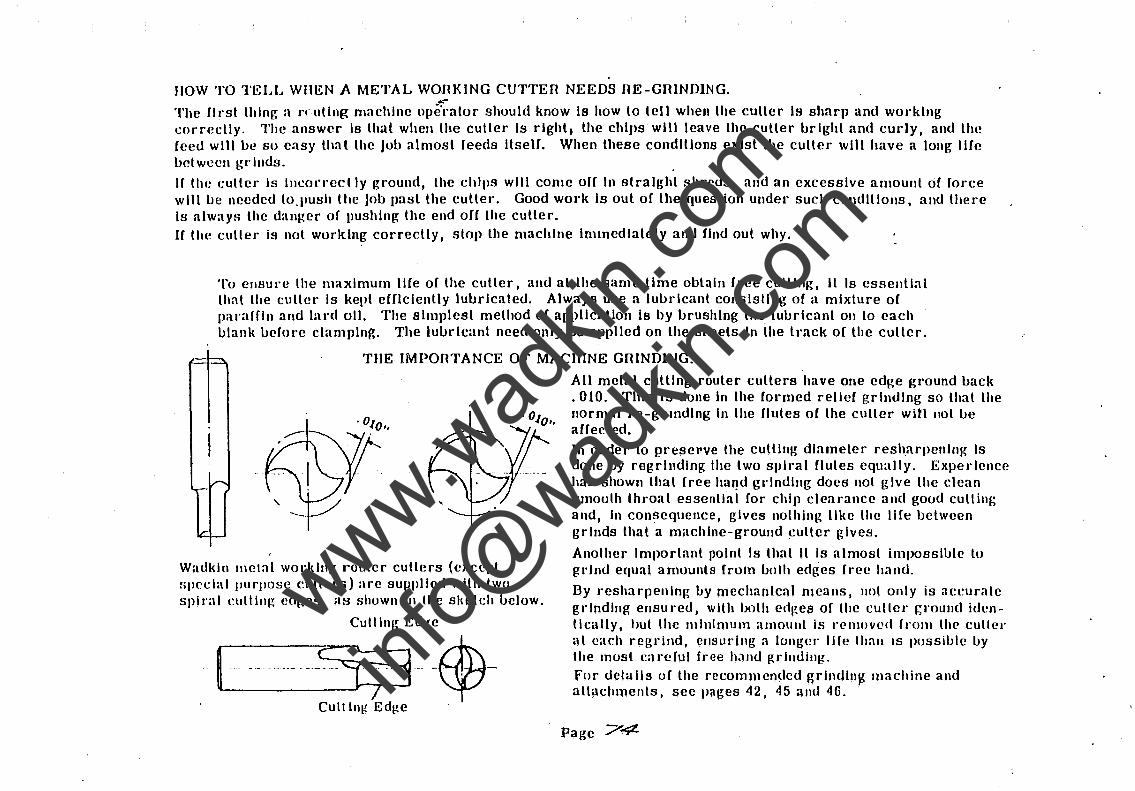
Wadkln metal worldll~ router cullers (except spec.:ial purpose eullers) are supplied with two spiral cuttinv, cdl~es, as shown III the sl(eteh uelow.
Culling Edge
I- -.. dU·Sf lfj . -$-Cult 11l~ Edge .
All metal cutllng router cullers have one edge ground back .010. This Is done In the formed relief grinding so that the normal re-grllldlng In the flutes of the culler win not be affected. In order to preserve the cutting diameter resh,arpenlng Is done by regrlndlng the two 8\>II"al (lutes equally. Experience has shuwn that free ha~d gl'lndlng docs nol give the clean smoolh throat essenllal for chip clearance and good culling and, In consequence, gives nothing like the life between grinds that a machine-ground ~utter gives,
Another Important point Is that It Is almost impossible to grind equal amounts (rom bolh edges free hand.
By resharpenlng oy mechanical means, lIot only is accurate grinding ensured, with both eti~es of the cullel' J;l'ound identlcally, hut the minimum amount is removed frolll the' culle!' at each regrind, ensuring a longel" life Ihall IS possihle by the most careful free hJ.nd ~rllldillg:, For details of the recommended grlndln~ machine and attachments, see pages 42. 45 alld 46. .
Page 74
www.wad
kin.co
m
info@
wadkin
.com
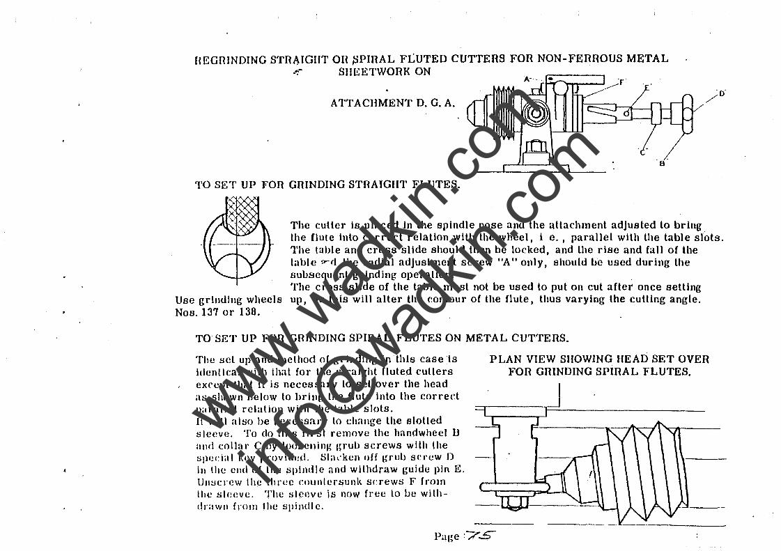
HEGfHNDING STIlA.IGHT 011 ~PIIlAL FLUTED CUTTERS FOR NON-FEIlIlOUS METAL --;- SIIEETWORK ON
ATTACHMENT D. G. A.
TO SET UP FOR GRINDING STRAIGHT FLUTES.
The cutter is placed In the spindle nose and the attachment adjusted lo bring the flure into correct relation with the wheel, i e. , parallel with the table slots. The table and cross slide should then be locked, and the rise and fall of lhe table ,....rt the radial adjustment s(:rew "A" only, should be used during the BulJscql!ent grinding operation. , The cross slide of the table must not be used lo put on cut after once setting
Use grinding wheels up, as this will alter the contour of the flute, thus varying the cutting angle. NOB. 137 or 138.
TO SET UP FOIl GRINDING SPIIlAL FLUTES ON METAL CUTTEIlS.
The !wt up and method of grinding in this case 'is identical with that for the straight fluted cullers except that it is necessary to set over the head as shown below to bring the flute into the cor red parallel relation with the table slots. H will also be necessary to change the slotted sleeve. To do this first remove the handwheel D and collar C by 10oseninJ,{ I~rub screws with the tipedal I,cy provided. Slackcn off grub SCI'CW J)
in the elld of thc spindle and withdraw guide pin E. lJlI!:lcrcw the three eounlersunk screws F from Ihe sleevc. The slc(wc is now free to be withdrawlI from thc spindle.
PLAN VIEW SHOWING HEAD SET OVER FOIl GIlINDING SPIIlAL FLUTES.
Page ~7S
www.wad
kin.co
m
info@
wadkin
.com
MC".I.'IIUU ut· liHlNl)lNU I'LU'l'l':H. UN 'l'Hli: A'I"['ACHhIlEN'I' I). G·.A
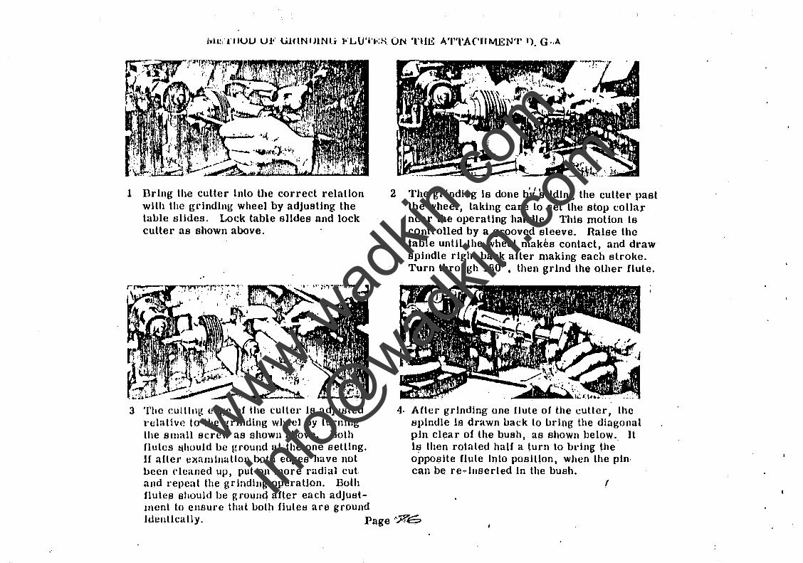
1 Bring the cutter Into the correct relation with the grinding wheel by adjusting the table slides. Lock table slldes and lock cutter as shown above.
. '
3 The cullltl~ edge of the culler Is adjusted relative to the ~rlllding wheel by tUrning the small screw as shown above. Both flutes &hould be ground at the one setting. H after examination both edges have not been cleaned up, put on more radial cut and repeil t the g r lading opera tlon. Both flutes should be ground after each adJust-ment to ensure that both fiutes are ground
2 The grinding is done bY sliding the cutter past lhe wheel, taking care to set the stop collar near the operating handle. This motion is controlled by a grooved sleeve. Raise the table until the wheel makes contact, and draw spindle right back after making each stroke. Turn through '1800
I then grind the other flute .
4· After grinding one flute of the cutter, the spindle ia drawn back to llrlng the diagonal pln clear of the bush, as shown below., It Is then rotated half a turn to bring the opposite flute Into position, when the pin, can be re-Inserted In the bush.
r
Identically. Page ''%6
www.wad
kin.co
m
info@
wadkin
.com
TYPICAL QHESTIONS AND ANSwERS ON METAL CUTTER SHARPENING.
Is a cutter recelved from the Stores r~ady (or use?
No. It requires honing or stoning before use. The, cutters are sent out as they leave the GrindIng Machine. They are not stoned up at our Works, as the cutting edges would be damaged in transit.
Is It permissible to use an oil stone on the outside of the cullers when dull?
ThIs Is the essence of routing and the key to high performance .. As soon as the cutter begins to drag, stop the machine and hone up the culler on the outer edges until they are sharp. This ean easily be done in half a minute and lhe method is iilustrated on pages 54 and 55.
How oUen should a metal working cutter be stoned?
About every hour. On hard material it may be every half hour. On some soft materials every two hours, but on aluminium and alclad sheets it pays to keep the cutter sharp to prevent pack-ing on lhe cutter. .
Bow many limes should a culler be stoned between regrinds?
A cutter should stand four lo eight stonings depending on the skIll of the operator.
Whal slone should be used and should it be used dry?
A No. 103 Carborundum Slip Stone. Dip the stone.in 011 and paraffin to give the best results.
Should lhe cullers be used dry on metal?
No. Always use a lubricaht consisting of paraffln and lard oil, mixed and applied to the sheets by brush before commencing to cut. The parartln is only a thinner to help to spread the lard all, ami only enough for lhe purpose 8hould be used. Excessive paraffln causes a blue smoke when cutting.
What eauses metal chips to pack on the cutter?
Generally, blunl cutters. The wrong shape of culler, especially on aluminium and alclad shecls will cause It, also a lack of lubricant ..
What causes chips to pack in lhe guide bush?
Blunt cutlers. They make shreds of swarf which work up inlo the bush and weld to the shank, If the cutter is cflrrec,t lhe large curly chips cannol possibly get Into the snupl clearance between cutter and gUide bush. .
What causes shudder when culling?
The culler has not been stoned. The rough saw edge left by the grinding wheel causes it. To cure 11 atone lhe cutter.
www.wad
kin.co
m
info@
wadkin
.com
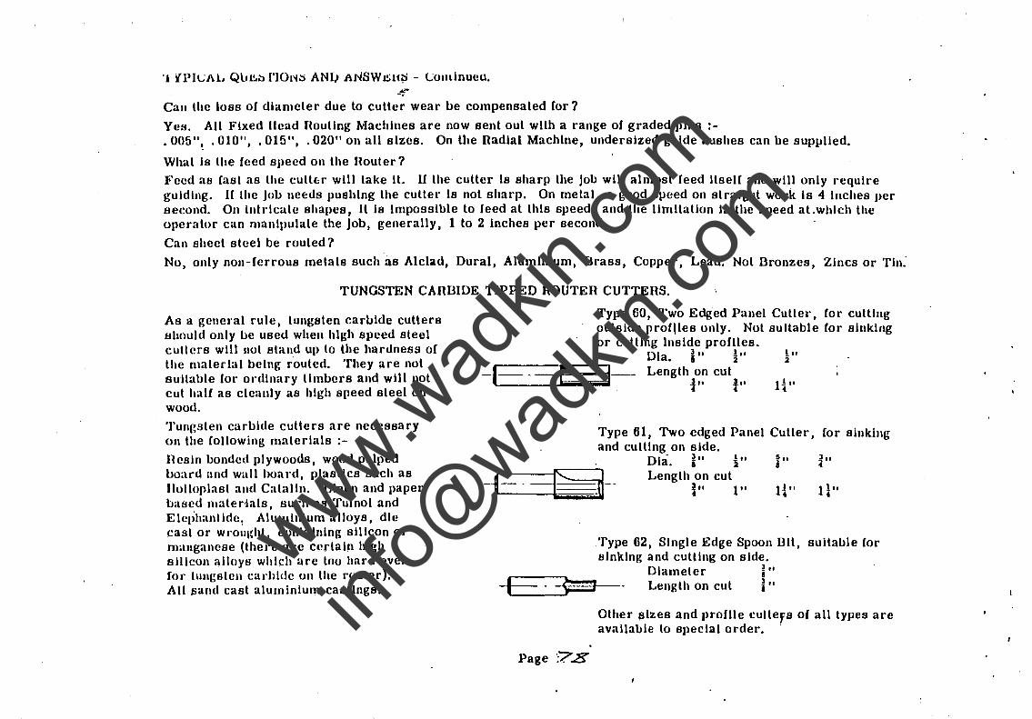
'J iPlcJ\L QU.l!.~ l'ION::; ANI) ANSW~U;:l - Condnueu. --. Can the loss of diameter due to cutler wear I.>e compensated for?
YeB. All Fixed Head Houtlng Machines are now sent out with a range of graded pins . 005"~ . 010", . 015", . 020" on all sizes. On the Radial Machine, undersized guide bushes can be supplied.
What Is the feed speed on the Router?
Feed as fast as the cutt{;f will take It. U the cutler Is sharp the job will almost feed Itself and will only J'equlre guiding. H the jol.> needs pushing the culter Is not sharp. On metal, a good speed on straight work Is 4 Inches per seeond. On Intricate shapes, It Is Impossible to feed at this speed, and the limitation Is the speed al.whlch the operator can manipulate the Job, generally, 1 to 2 inches per second.
Can sheet steel be routed?
No, only non-ferrous metals such as Alclad, Dural, Aluminium, Brass, Copper, Lead. Not Bronzes, ZlncB or Tin:
TUNGSTEN CARBIDE TIPPED ROUTER CUTTERS.
As a general rule, tungsten carbide cutters should only be used when high speed steel cullers will not stand up to the hardness of the material being routed. They are not suitable for ordinary lIml.>ers and will not cut half as cleanly as high speed steel on wood.
Tungsten carbide cutters are necessary on the following materials :-
Resin bonded plywoods, wood pulped board and wall boal'd, plastics such as lIolloplast alld Catalln. Linen and paper based mater-Iats, such as Tufnol and Elet;hanllde: Aluminium allOYS, die cast or WJ'olll{ht, containing silicon or manganese (there are certain high silicon alloys which arc too hard even (01' tungsten cal'blde on the router). All "and cast aluminium castings.
--1-- f
Type 60, Two Edged Panel Cuttel', for cutting outside prOfiles only. Not suitable for sinking or cutting Inside profiles.
Dla. jtt ~" _ Length on cut
1" tot
! .. 2
Type 61, Two edged Panel Cutter, (or sinking and cutllng on side.
- 1 1 !i ] Dla. i" 2" j" i"
___ 1 __ -sa===e-- Length on cut -, ~ i" 1" I{" n"
Type 62, Single Edge Spoon BIl, suitable for sinking and cutting on side.
Diameter ~" -E . ~--- Length on cut j"
Page :7.8
Other sizes and profile cuttefs of all types are available to special order. -
www.wad
kin.co
m
info@
wadkin
.com
.o!" -.
SHARPENING TUNGSTEN CARBIDE ROUTER CUTTERS.
Tungsten c~rb.ide cullers cannot be sharpened with ordinary grinding wheels or honed with Carborundum honing stones. The grinding- can be done on the N. U. Grinder and S. F. A. Attachment described on pages 45-46, using grinding wheels 86" and 87" descTlbed on page 46. Use the wheels dry; 86R for roughing, taking very light ("uts, and expect lo take a long time removing a: small amount of carbide. Finish grind dry, using wheel 87R. In order to get a good cutting edge it Is necessary to machine lap with wheel No. 145. This wheel is made from sort material and Its cutting edge Is Impregnated with diamond dust It Is expensive to use and should he used for final finishing. It can, of course, be used for grinding In place of the f.6R and 87" wheels, hut the wear and cost of the laps would be prohibitive. Never attempt to true the diamond lap. When using the machine lap smear the face of the wheel with oil and then tal{c the lightest possible cuts to get a polished face and a clean edge. Finish the cutting edge with a hand lap, which Is also Impregnated with diamond dust and is illustrat.ed on page 47.
The best method of using the hand lap .Is to Immerse the lap and tool under water and hone In this potiillon. This Is recommended so that the diamond dust freed from the lap floats to the surface of the water and does not become abrasive between the cutler and the lap, causing excessive wear on the lap. If this Is not pOSSible, use as much water as possible to swill off the diamond dust.
The general Instructions on stoning cutters on pages 54-55 apply to tungsten carbide cutters except that the diamond lap is used instead of the Carborundum stone.
Tungsten carbide cutters sent out from our Works require honing with the hand lap.
,
Page iK9
www.wad
kin.co
m
info@
wadkin
.com
"
CONCERNING CUTTER COLLETS.
Never over-tighten a collet. The short spanner or screw key 'provided
is desIgned to give the maximum grIp, when used by the average
operator. The use or a pipe wrench strains the collet and actually
reduces the gr lp on the cutter.
Never allow cutters to project from the collet more than is absolutely
necessary. It Is a golden rule that the nearer the cutter to the collet,
the belter the cut and the longer the life oc. the cutter.
(
Page ·8C>
www.wad
kin.co
m
info@
wadkin
.com