user manual - ocean technology systems
TRANSCRIPT

User ManUal

i- NOTICE -
All users are instructed to read and fully understand the PowerCom manual before using. This manual and the information contained herein are provided for use as a maintenance and operation guide. No license or rights to manufacture, produce, and/or sell either the manual or articles described herein are given. Undersea Systems International, Inc., dba Ocean Technology Systems hereinafter referred to as OTS, reserves the right to change specifications without notice. We recommend that all users read and fully understand this manual before using a PowerCom.
All statements, technical information, and recommendations herein are based on tests we believe to be reliable, but the accuracy or completeness thereof is not guaranteed; and the following is made in lieu of all warranties, expressed or implied, including the implied warranties of merchantability and fitness for purpose: Seller’s and Manufacturer’s only obligation shall be to replace such quantity of the product proved to be defective. Before using, the user shall determine the suitability of the product for intended use, and the user assumes all risk and liability whatsoever in connection therewith. Neither Seller nor Manufacturer shall be liable either in tort or in contract for any loss or damage—direct, incidental, or consequential—arising from the use of or the inability to use the product. No statement or recommendation not contained herein shall have any force or effect unless it is in an agreement signed by officers of the Seller and Manufacturer.
- IMPORTANT SAFETY NOTICE -(Please read before using product)
It is absolutely essential that all users are certified divers in good standing, properly trained, equipped, and fully understand this user’s manual before attempting to use the PowerCom. While the PowerCom does provide the diver with the ability to communicate underwater, it does not change or eliminate the potential hazards of diving.
Refer to the User Manuals page of our Website at: www.oceantechnologysystems.com for a list of any changes made to this
manual since its publication.
© Copyright 2020, 2021 by Undersea Systems International, Inc., dbaOcean Technology Systems. All rights reserved.
Specifications are subject to change without prior notice.
Date Published: February 25, 2021
OTS PO
WERC
OM

CAUTION
The PowerCom uses Lithium-Ion rechargeable batteries which can explode or cause fire if damaged or stored incorrectly.
IF STORED INCORRECTLY OR DAMAGEDRead and follow the Battery Warnings, Cautions and Prohibitions below before using.
BATTERY WARNINGPowerCom contains Lithium-Ion battery pack. Proper handling should always be taken to ensure the battery will operate at its optimum level. Mishandling or misuse of the battery could potentially affect the performance and reliability of the battery.
CAUTIONS FOR USE AND HANDLING
• Please read the manual before charging.
• Battery contains a protection circuit to prevent damage to the battery during use. Care must be taken to ensure the battery is not damaged.
• If the battery will not take a charge (LED on the charger does not switch from Red to Green) after about 2 hours, discontinue charging. Please contact OTS for further instructions.
• Battery must be charged at a temperature range between 0°C (32°F) and 45°C (113°F). Battery operation should be between –10°C (14°F) and 60°C (140°F).
• Battery can be stored separately from the unit.
• For long term storage, battery should be stored in a cool dry area at a temperature between –20°C (–4°F) to 25°C (77°F).
• Do not place the battery in direct sunlight or in direct contact with a heat source.
• Do not use the battery in high static environment where the battery can be damaged due to static electricity.
• If rusted or if the battery emits an unusual odor, please contact OTS.
ii
OTS PO
WERC
OM
• The battery must be stored away from children and pets.
• Lithium-Ion batteries have a predefined number of charge cycles, if the batteries won’t hold the charge or requiring more frequent charging, the battery may need to be replaced.
• When storing two or more individual batteries in the same location, ensure the battery contacts are protected from coming into contact with another battery.
• Do not use this battery for other application.
• If the battery is completely drained, charging will be necessary to maintain the health of the battery. Do not leave a completely discharged battery in storage for a long period without charging. (Greater than 6 months)
• Do not allow anything conductive material to come in contact with the battery terminals. Do not store with coins, paperclips, wire, etc. This will result in a short circuit that may cause damage and/or fire. Use insulative tape over the contacts if needed.
iii
OTS PO
WERC
OM

Danger Note
In handling the battery, always place the battery with the contacts facing upwards as shown below. Placing the battery with the contacts facing down against a surface could potentially cause a short, causing fire or death.
PROHIBITIONS
• Only use the battery charger provided by OTS to charge the battery. This charger has been tested and qualified to be reliable for all use. Do not use an unapproved charger. An unapproved charger could result in an over charge state and potentially damage the battery. Using an unapproved charger will void your warranty.
• Do not disassemble or reconstruct the battery.
• Do not throw, drop, or cause impact to the battery.
• Do not pierce a hole or puncture the battery with sharp objects.
• Do not use any other batteries or cells in this unit.
• Do not apply solder on the battery.
• Do not expose the battery to high termperature greater than 60°C (140°F).
• Do not put the battery into a microwave or high pressure container.
• Do not connect positive(+) and negative(-) contacts with any conductive materials (such as metal or wire).
• Do not allow the battery to get wet or immerse in water.
• If you suspect that water has breached the unit, do not open the unit if the unit is hot to the touch. Let the unit cool completely before handling. Contact OTS for further instructions.
Rechargeable Lithium-Ion battery
iv
OTS PO
WERC
OM

v
OTS PO
WERC
OM

1
OTS PO
WERC
OM
TABLE OF CONTENTSImportant Safety Notice .................................................................iBattery Warning .............................................................................ii
Cautions for Use And Handling .................................................... iiProhibitions ................................................................................. iv
Table of Contents ..........................................................................1Introduction ....................................................................................2General ...........................................................................................2Specifications ................................................................................3Anatomy of The PowerCom ..........................................................4Startup Guide .................................................................................7Making Adjustments .....................................................................8
Default settings ............................................................................9Channel ......................................................................................10Volume .......................................................................................10Squelch ......................................................................................10Transmit ..................................................................................... 11Scrambler ................................................................................... 11
Battery Charging .........................................................................12Low Battery Indicator ..................................................................12Battery Disposal ..........................................................................12Maintenance .................................................................................12
PRE-DIVE PROCEDURE FOR ESTABLISHING COMMUNICATIONS ................................................................12POST-DIVE ...............................................................................13Troubleshooting Guide ...............................................................14Maintenance Intervals ................................................................15
Replacement/Spare Parts ...........................................................16Battery Replacement ..................................................................16O-ring Replacement ...................................................................16Transducer Removal and Replacement .....................................17Belt Clip Replacement ................................................................18Spare Part Ordering Instructions ................................................18
Understanding Wireless Underwater Communications ..........19Limited Warranty .........................................................................22
2
OTS PO
WERC
OM
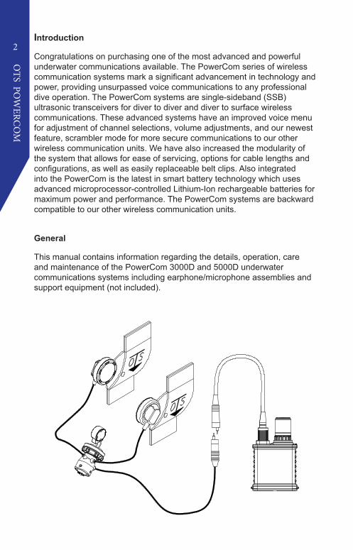
Introduction
Congratulations on purchasing one of the most advanced and powerful underwater communications available. The PowerCom series of wireless communication systems mark a significant advancement in technology and power, providing unsurpassed voice communications to any professional dive operation. The PowerCom systems are single-sideband (SSB) ultrasonic transceivers for diver to diver and diver to surface wireless communications. These advanced systems have an improved voice menu for adjustment of channel selections, volume adjustments, and our newest feature, scrambler mode for more secure communications to our other wireless communication units. We have also increased the modularity of the system that allows for ease of servicing, options for cable lengths and configurations, as well as easily replaceable belt clips. Also integrated into the PowerCom is the latest in smart battery technology which uses advanced microprocessor-controlled Lithium-Ion rechargeable batteries for maximum power and performance. The PowerCom systems are backward compatible to our other wireless communication units.
General
This manual contains information regarding the details, operation, care and maintenance of the PowerCom 3000D and 5000D underwater communications systems including earphone/microphone assemblies and support equipment (not included).
3
OTS PO
WERC
OM
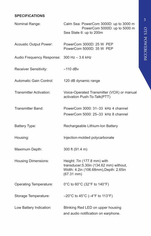
SPECIFICATIONS
Nominal Range: Calm Sea: PowerCom 3000D: up to 3000 m PowerCom 5000D: up to 5000 m
Sea State 6: up to 200m
Acoustic Output Power: PowerCom 3000D: 25 W PEP PowerCom 5000D: 35 W PEP
Audio Frequency Response: 300 Hz – 3.6 kHz
Receiver Sensitivity: –110 dBv
Automatic Gain Control: 120 dB dynamic range
Transmitter Activation: Voice-Operated Transmitter (VOX) or manual activation Push-To-Talk(PTT)
Transmitter Band: PowerCom 3000: 31–33 kHz 4 channel PowerCom 5000: 25–33 kHz 8 channel
Battery Type: Rechargeable Lithium-Ion Battery
Housing: Injection-molded polycarbonate
Maximum Depth: 300 ft (91.4 m)
Housing Dimensions: Height: 7in (177.8 mm) with transducer;5.30in (134.62 mm) without, Width: 4.2in (106.68mm),Depth: 2.65in (67.31 mm)
Operating Temperature: 0°C to 60°C (32°F to 140°F)
Storage Temperature: –20°C to 45°C (–4°F to 113°F)
Low Battery Indication: Blinking Red LED on upper housingand audio notification on earphone.

4
OTS PO
WERC
OM
ANATOMY OF THE POWERCOM
Transducer Assembly:912020-000 TA-4 (PowerCom 5000D)912015-000 TA-5 (PowerCom 3000D)
Transducer O-ring: 283003-000
Earphone/Microphone Connector:
Main Housing
Belt Clip:137084-000
Housing O-ring:283058-000
Rubber Armored Base O-ring:283059-000
Microprocessor controlled Smart Battery:910505-000
Rubber Armored Base:133061-000
Sealing Screw O-ring:283060-000
Sealing Screw:244254-000
Earphone/Microphone Cable:
Transducer Ring

5
OTS PO
WERC
OM
EARPHONE/MICROPHONE (EM) CABLE
The EM cable connects the EM Connector to an EM assembly with an 8-pin connection. The threaded locking collar can be tightened to make a secure connection to the PowerCom unit.
TRANSDUCER ASSEMBLY
The Transducer Assembly acts as the “antenna” of the unit. Transducers are replaceable.
TRANSDUCER RING
The Transducer Ring is a rotating locking ring that secures the Transducer or Transducer Cable (TCA-35S) when used with the CDK-6 Surface Conversion Kit.
EARPHONE/MICROPHONE (EM) CONNECTOR
The EM connector at the top the unit connects the PowerCom to an EM assembly and to the battery charger. Modularity allows for easy replacement for repairs or optional cable assemblies.
MAIN HOUSING
The main housing of the unit contains the electronics and battery compartment of the system. The connectors to the Transducer and the Earphone/Microphone cables are user replaceable. The Belt Clip located at the back of the unit is also user replaceable. Do not disassembled the main housing beyond this point. Doing so could potentially void any warranties. Main housing should only be accessed by an authorized technician.
BELT CLIP
The belt clip can be mounted on a belt or on a BCD tank strap. For bestrange between divers and surface station, it is recommended to mountthe unit as far back on the tank strap as possible.
RECHARGEABLE LITHIUM-ION BATTERY
The Lithium-Ion battery provides power to the Powercom unit. The battery is located on the lower cavity of the unit on a strip of Velcro inside the Rubber Armored Base. This battery does not require any maintenance other than charging.
6
OTS PO
WERC
OM
RUBBER ARMORED BASE
The Rubber Armored Battery Base protects the unit from impact and reduces abrasion damage as well as sliding on smooth surfaces.
SEALING SCREWS
The Sealing Screws are captive to the Rubber Armored Base. The Sealing Screws remain connected to the Rubber Armored Base even when fully disengaged from the Main Housing. Each screw contains an O-ring to seal the Rubber Armored Base to the Main Housing. To prevent possible water intrusion into the unit, ensure the Sealing Screws are tightened properly before beginning the dive.
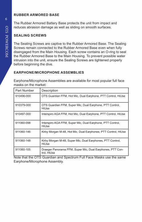
EARPHONE/MICROPHONE ASSEMBLIES
Earphone/Microphone Assemblies are available for most popular full face masks on the market:Part Number Description910496-000 OTS Guardian FFM, Hot Mic, Dual Earphone, PTT Control, HiUse
910379-000 OTS Guardian FFM, Super Mic, Dual Earphone, PTT Control, HiUse
910497-000 Interspiro AGA FFM, Hot Mic, Dual Earphone, PTT Control, HiUse
911060-098 Interspiro AGA FFM, Super Mic, Dual Earphone, PTT Control, HiUse
911060-146 Kirby Morgan M-48, Hot Mic, Dual Earphones, PTT Control, HiUse
911060-148 Kirby Morgan M-48, Super Mic, Dual Earphones, PTT Control, HiUse
911060-105 Draeger Panorama FFM, Super Mic, Dual Earphones, PTT Con-trol, HiUse
Note that the OTS Guardian and Spectrum Full Face Masks use the same Earphone/Microphone Assembly.

7
OTS PO
WERC
OM
START-UP GUIDE
Before diving, ensure the Lithium-Ion battery is fully charged.
To charge the battery, remove the Earphone/Microphone (EM) cable by unscrewing the locking collar that retains the cable to the connector in a counter-clockwise direction on the top of the housing. With the collar free, grip the connector and pull straight up WITHOUT twisting to disconnect the cable. Then, connect the battery charger to the corresponding connector on the PowerCom.
When connecting the Battery Charger Cable to the PowerCom unit, take caution when mating the connectors. Ensure the two larger guide pins are correctly aligned with the two larger sockets. Do not force the connectors to mate. Connection should be smooth when the pins are aligned with the sockets. Excessive force could result in connector failure or breakage.
When the Battery Charger is connected to the unit, the LED on the Battery Charger will turn GREEN then switch to RED if the battery requires a charge. If not, the LED will remain GREEN to indicate the battery is full.
The LED on the Powercom unit is a single color LED. When lit, it indicates the unit is charging or activated.
Disconnect the Battery Charger from the unit and connect your EM Cable to the EM Assembly connector.
Your PowerCom is now ready for use.
The unit was designed to automatically turn on when it comes in contact with water. The two metal posts between the transducer and the connector on top of the unit are the water switch. To check or adjust your settings prior to dive, the unit can be turned on by placing a metallic object (like a small screwdriver) onto the two metal posts. Remove the metallic object after you have confirmed your settings. The unit will automatically shut off after 30-40 seconds. Do not leave the metallic object on the unit as doing so will drain the battery.

8
OTS PO
WERC
OM
MAKING ADJUSTMENTS
The PowerCom uses a voice menu system. This allows for adjustments of settings without the need for buttons or knobs penetrating the housing. Using a sequence of easily learned manipulations of the Push-To-Talk (PTT) button on the Earphone/Microphone Assembly allows you to control all of the features of the PowerCom. It’s recommended that you take a few minutes and learn how to use the voice menu and all of the features.
To change your settings, depress the PTT button of the Earphone/Microphone Assembly three times about ¹⁄2 seconds apart, holding the button down on the third press for around one second. The PowerCom will now enter an adjustment mode. You will hear a voice saying “Channel, Volume, Squelch, Transmit, Scrambler” This message will repeat a second time and exit if no selection is made. To select an option, press the PTT button once when you hear the setting you want to change. This will prompt a sub-menu that will read additional choices. A table of the complete menu is provided. Depress the PTT button again whenever you hear the option you want. Once a change has been made, the unit will repeat your choice then exit.
For example, to change the volume setting to “MEDIUM”, you will push the PTT control three times holding the third push for approximately one second, then release the PTT button. The Voice Menu will start reading your options and you will hear: “Channel, Volume, Squelch, Transmit, Scrambler”….When you hear “VOLUME, you would depress the PTT button. This will trigger a sub menu giving you your choice of volume. You will choose from the following: “Receive, Side, Receive, Side (see page 10 for explanation of VOLUME). If you want to hear the messages coming in at a MEDIUM volume, you would depress when you hear “Receive”. If you wanted to hear your volume monitoring your communications, when you hear “Side” you would depress the button. At this point once you make a selection from “Side” or “Receive”, the unit gives you the option to choose Volume settings (i.e. Low, Medium, High, Extra High). Once the selection is made, the Powercom unit will read back a confrimation of the changed setting then exit.
9
OTS PO
WERC
OM
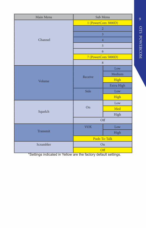
Main Menu Sub Menu
Channel
1 (PowerCom 3000D)23456
7 (PowerCom 5000D)8
VolumeReceive
LowMedium
HighExtra High
Side LowHigh
SquelchOn
LowMedHigh
Off
TransmitVOX Low
High
Push-To-TalkScrambler On
Off *Settings indicated in Yellow are the factory default settings.

10
OTS PO
WERC
OM
CHANNEL
In the channel selection menu, the transceiver will offer you channels 1, 2, 3, and 4 (PowerCom 3000D), or 1, 2, 3, 4, 5, 6, 7, and 8 (PowerCom 5000D), depending on which system you have. Depress the PTT button when you hear the channel you want. After you have made the selection, the transceiver will repeat your selection then exit.
Channel Number Frequency
Channel 1 32.768kHz Upper Sideband
Channel 2 32.768kHz Lower Sideband
Channel 3 31.250kHz Upper Sideband
Channel 4 31.250kHz Lower Sideband
Channel 5 28.500kHz Upper Sideband
Channel 6 28.500kHz Lower Sideband
Channel 7 25.000kHz Upper Sideband
Channel 8 25.000kHz Lower Sideband
VOLUME
There are two selections for Volume, “Receive” and “Side”. Receive is how loud you hear the audio from incoming transmissions on the Earphone/Microphone Assembly. Side, or Side Tone, is how loud you hear yourself. Side Tones is also useful for confirmation the transmitter is working. If the unit has an issue where you are not transmitting, you will not hear yourself through the Earphone/Microphone Assembly. Recieve and Side Tone have four settings.
SQUELCH
The “Squelch” option is designed to help eliminate background noise. Unfortunately, there are a lot of noises in the spectrum used for Wireless Communications. Marine biological noise, especially shrimp, can be considerable and sounds like “static”. Mechanical noise can come from numerous sources such as boat engines, compressors, generators, jet skis, and even rain can affect wireless communications. Anything that produces sound can be heard though the PowerCom if the signal is in the ultrasonic frequency.
Think of Squelch as a gate that allows only the strong signal of other divers or the surface station through to your Earphone/Microphone Assembly. If the water is particularly “noisy” you may

11
OTS PO
WERC
OM
want to turn the Squelch on and set it to the high setting. Note that when set to the high setting, you may be limiting the signal from a diver or surface station if they are shadowed or distant, effectively limiting the range. If the water is particularly quiet or you need to hear a potentially weak signal from a distant diver/surface station, then you may want to turn the Squelch off or select the low setting.
TRANSMIT
Under the transmit options menu, you can choose between manual Push-To-Talk (PTT) transmission or automatic Voice Operated Transmission (VOX). In manual PTT mode, the unit will only transmit for as long as you hold down the PTT button. In VOX mode, the unit will transmit when it detects speech. The VOX mode will require the sensitivity to be set per individual for best results and may take a couple dives to fit your diving needs. The unit will prompt you for either “High” sensitivity or “Low” sensitivity.
VOX often takes some practice to use effectively. Understanding how the system works will help in using this feature. The system first has to detect that you have started speaking and will often “clip” your first word. When you are finished speaking, it takes a brief time to recognize that there is no more voice to transmit and closes the transmission. If the sensitivity is too high, false triggering can be an issue. If the sensitivity is too low, it can cause the unit to not trigger easily or cease transmission too soon. Microphone position can also be critical with using VOX. The microphone should be no farther than ¹⁄4” away from your lips. Also note that, Wireless communications are half-duplex, meaning you are either transmitting or receiving, not both at the same time. Lastly, it’s important to note that if the VOX system false triggers, you cannot hear other divers or the surface.
SCRAMBLER
To turn on or off the “Scrambler” option, depress the PTT button once when “Scrambler” is heard. Your next choice will be “On” or “Off”. Press the PTT to make the selection you want. Scrambling enables the divers to have more secure communication while the option is on. Divers with this feature will be able to hear normal speech, while divers without will hear unintelligible transmissions, providing an additional layer of secure voice communications.
12
OTS PO
WERC
OM
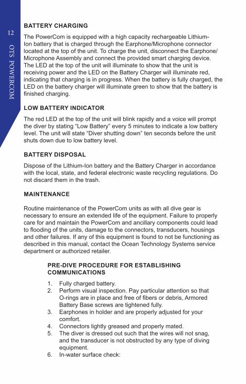
BATTERY CHARGING
The PowerCom is equipped with a high capacity rechargeable Lithium-Ion battery that is charged through the Earphone/Microphone connector located at the top of the unit. To charge the unit, disconnect the Earphone/Microphone Assembly and connect the provided smart charging device.The LED at the top of the unit will illuminate to show that the unit isreceiving power and the LED on the Battery Charger will illuminate red, indicating that charging is in progress. When the battery is fully charged, the LED on the battery charger will illuminate green to show that the battery is finished charging.
LOW BATTERY INDICATOR
The red LED at the top of the unit will blink rapidly and a voice will prompt the diver by stating “Low Battery” every 5 minutes to indicate a low battery level. The unit will state “Diver shutting down” ten seconds before the unit shuts down due to low battery level.
BATTERY DISPOSAL
Dispose of the Lithium-Ion battery and the Battery Charger in accordance with the local, state, and federal electronic waste recycling regulations. Do not discard them in the trash.
MAINTENANCE
Routine maintenance of the PowerCom units as with all dive gear is necessary to ensure an extended life of the equipment. Failure to properly care for and maintain the PowerCom and ancillary components could lead to flooding of the units, damage to the connectors, transducers, housings and other failures. If any of this equipment is found to not be functioning as described in this manual, contact the Ocean Technology Systems service department or authorized retailer.
PRE-DIVE PROCEDURE FOR ESTABLISHING COMMUNICATIONS
1. Fully charged battery.2. Perform visual inspection. Pay particular attention so that
O-rings are in place and free of fibers or debris, Armored Battery Base screws are tightened fully.
3. Earphones in holder and are properly adjusted for your comfort.
4. Connectors lightly greased and properly mated.5. The diver is dressed out such that the wires will not snag,
and the transducer is not obstructed by any type of diving equipment.
6. In-water surface check:

13
OTS PO
WERC
OM
a. Recheck the location of the earphones.b. Submerge the transducer to activate unit. Establish communication with divers and/or surface station.
c. Look your dive partner over to ensure his equipment is properly adjusted and the wires are dressed so as not to snag.Ensure the unit is secured properly to where it is mounted. 7. Ensure the unit is secured properly to where it is mounted.
POST DIVE PROCEDURE
1. Rinse the unit in freshwater for several mintues or until the unit is clean. A mild soap solution may be used to remove contaminants and after cleansing, rinse with freshwater.
2. Dry the transceiver with a clean towel, especially around the area of the activating water-contact screws. This will ensure the unit will shut off. Failure to do so will drain the battery Note: The unit may take a few minutes to turn off; this is normal.
3. Store in a dry, safe area.4. Similar maintenance should be performed on all ancillary
equipment5. Routinely clean the water switch contacts with soft brush to
remove any contaminants or oxidation in this area.

14
OTS PO
WERC
OM
TROUBLESHOOTING GUIDE
Contact Ocean Technology Systems for any issues not listed below:
Issue Step 1 Step 2
No/Low Transmit
Change E/M to isolate issue
Contact OTS.Change E/M Adapter
Move Mic Close to lips
Ensure Transducer is not covered by equipment
Change Transducer
No Receive Volume
Change E/M to isolate issue
Contact OTS.
Change E/M Adapter
Ensure Transducer is not covered by equipment
Change Transducer
Reduce distance to divers
Scrambler setting “stuck” Contact OTS.
Transmission setting “stuck” on PTT
Contact OTS.
No Side Volume Contact OTS.
Charger LED illuminates green but the unit LED
does not activateContact OTS.
Charger LED illuminates green, unit LED illuminates
red, but the unit will not activate when submerged.
Battery is “dead”. Replace the battery. Contact OTS.
Short Battery Life when fully charged
Replace the battery.
Flooding in battery com-partment
Replace the battery. (See page iv for safety warning on handling a flooded battery compartment)
Flooding in electronics compartment
Do not attempt to power on the unit. Contact OTS.
Unit LED activates with no start up volume and no
transmit or receiveContact OTS for replacement
15
OTS PO
WERC
OM
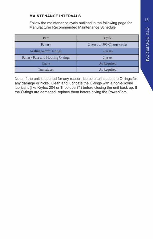
MAINTENANCE INTERVALS
Follow the maintenance cycle outlined in the following page forManufacturer Recommended Maintenance Schedule
Part Cycle
Battery 2 years or 300 Charge cycles
Sealing Screw O-rings 2 years
Battery Base and Housing O-rings 2 years
Cable As Required
Transducer As Required
Note: If the unit is opened for any reason, be sure to inspect the O-rings for any damage or nicks. Clean and lubricate the O-rings with a non-silicone lubricant (like Krytox 204 or Tribolube 71) before closing the unit back up. If the O-rings are damaged, replace them before diving the PowerCom.

16
OTS PO
WERC
OM
REPLACEMENT/SPARE PARTS
Most parts of the PowerCom unit can be replaced by the end user. The Modularity of the system allows for easy replacement of the Battery, Belt Clip, Transducers and Earphone/Microphone Cables. Any electronic components of the housing and the Lid Assembly can only be replaced by Ocean Technology Systems or an authorized technician.
DO NOT use silicone grease on the silicone o-rings. This could cause swelling and damage of the o-ring resulting in a failure of the pressure housing. Use only non-silicone grease. Krytox 204 or Tribolube 71 are acceptable lubricants. Use of silicone based lubricants will void any warranties.
If you need spare parts contact us at: [email protected] or (714) 754-7848
BATTERY REPLACEMENT
1. Using a large flat head screw driver, loosen the screws on the bottom of the unit as shown. Rotate the screws counter-clockwise until the screw comes free from the main housing.
2. Push on the finger tabs located on the Rubber Armored Base to separate the battery cover from the rest of the unit. If the screws were not loosened sufficiently, they may become stuck. Do not force the unit open. Loosen the screws until free from the threads. The cover should come free with gentle force.
3. After removing the cover, the battery is secured to the cover by a velcro strip. Simply pull the battery free from the cover and replace with the fresh battery.
17
OTS PO
WERC
OM
O-RING REPLACEMENT
It is recommended that the o-rings be are serviced per Manufacturer Recommended Maintenance Schedule. Anytime the Rubber Armored Base or Transducer is removed, the o-rings should be cleaned, inspected and lubricated. Use only o-rings supplied by OTS for this purpose. Use of aftermarket or otherwise sourced o-rings will void any warranties. Clean, inspect and lubricate all o-rings even if new.
1. Remove the damaged O-Ring using a dull plastic tool. Ensure that no damage is done to the sealing surfaces of the unit.
2. Lightly grease O-Ring with grease included in the O-Ring replacement kit.
3. Place the O-Ring gently into the O-Ring grooves, taking extra care not to stretch the rubber of the O-Ring. Ensure the O-ring rests compeletly inside the groove.
4. To replace the Sealing Screw O-rings, there is a second set of threads in the Rubber Armored Base, continue to unscrew by pulling lightly on the Sealing Screw while unscrewing counter-clockwise. The Sealing Screw will extract exposing the Sealing Screw O-rings.
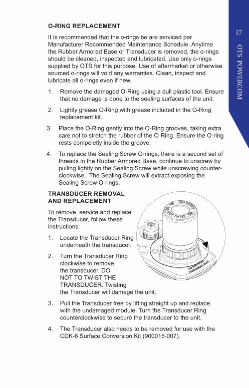
TRANSDUCER REMOVAL AND REPLACEMENT
To remove, service and replace the Transducer, follow these instructions:
1. Locate the Transducer Ring underneath the transducer.
2. Turn the Transducer Ring clockwise to remove the transducer. DO NOT TO TWIST THE TRANSDUCER. Twisting the Transducer will damage the unit.
3. Pull the Transducer free by lifting straight up and replace with the undamaged module. Turn the Transducer Ring counterclockwise to secure the transducer to the unit.
4. The Transducer also needs to be removed for use with the CDK-6 Surface Conversion Kit (900015-007).

18
OTS PO
WERC
OM
BELT CLIP REPLACEMENT
If the Belt Clip is damaged, follow these instructions to replace the Belt Clip:
1. Using a #4 Phillips screw driver, loosen the three screws that secure the Belt Clip to the unit and remove damaged Belt Clip
2. Replace the Belt Clip with the new Belt Clip and re-tighten the screws. Do not over torque the screws.
SPARE PART ORDERING INSTRUCTIONS
Spare parts are available to purchase from OTS.
To Purchase, contact OTS at: [email protected]
Part Number Part Description
900474-000 RBLi-4, LITHIUM BATTERY KIT
900474-001 AD8PMHI17, 8-PIN TO HI-USE CABLE KIT
900474-002 RUBBER ARMORED BASE ASSEMBLY KIT
900474-003 BELT CLIP KIT
900474-005 RCLi-1 BATTERY CHARGER KIT,US
900474-009 POWERCOM/MILCOM O-RING KIT
900474-010 TRANSDUCER O-RING KIT
900474-011 TA-5 TRANSDUCER KIT
900474-012 TA-4 TRANSDUCER KIT
19
OTS PO
WERC
OM
UNDERSTANDING WIRELESS UNDERWATER COMMUNICATIONS
FACTORS THAT AFFECT WIRELESS COMMUNICATIONS
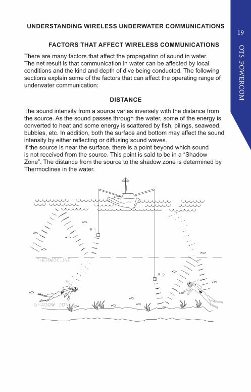
There are many factors that affect the propagation of sound in water. The net result is that communication in water can be affected by local conditions and the kind and depth of dive being conducted. The following sections explain some of the factors that can affect the operating range of underwater communication:
DISTANCE
The sound intensity from a source varies inversely with the distance from the source. As the sound passes through the water, some of the energy is converted to heat and some energy is scattered by fish, pilings, seaweed, bubbles, etc. In addition, both the surface and bottom may affect the sound intensity by either reflecting or diffusing sound waves.If the source is near the surface, there is a point beyond which sound is not received from the source. This point is said to be in a “Shadow Zone”. The distance from the source to the shadow zone is determined by Thermoclines in the water.
20
OTS PO
WERC
OM
WATER TEMPERATURE
Variations in water temperature affects sound transmission most. In some areas of the ocean, the temperature changes at a fixed rate over large ranges of depth. If the temperature increases with depth, the velocity of sound increases and the sound waves will be refracted toward the surface. If, however, the temperature decreases with the depth, the velocity of sound decreases and the waves of sound are bent downward.
There are also areas in the sea where temperature changes rapidly over a small depth range called a thermocline. Thermoclines can to produce a sharp bending of sound waves and may serve as reflecting surfaces.The velocity of sound transmission changes only about one percent for a temperature change of l0°F. However, the bending of the sound path has great effect over a distance of several hundred yards.
If the temperature of the water decreases with depth at the rate of 1°F for each 30 feet (starting at the surface), most of the sound energy originating at the source near the surface will travel along paths that are bent downward. Therefore, the sound energy may not reach a shallow detector positioned l,000 yards from the source but may reach a deeper detector position further from the source. Greater temperature variations can cause these paths to bend more sharply. The best method to deal with thermoclines is to bring the divers and/or transducers as close to each other as possible.
If a diver enters a thermocline, the diver should report it to everyone (surface and divers) so they know the depth of the thermocline. All divers should stay within that depth, and the surface station should try to position the surface transducer below or above, whichever is the case.
WATER DENSITY
Water density is important for the propagation of the sound. Because the density of sea water varies with temperature, salt content, and static pressure, the effect on sound of each of these three factors is usually considered separately.
BACKGROUND NOISE
Marine organisms play an important role in underwater acoustics. They are important primarily because of the effect they have on sound transmission, but they often serve as sources of underwater noise as well. High background noise can interfere with good communications. Such background noise can be mitigated with the squelch function.
21
OTS PO
WERC
OM
ZONES OF SILENCE
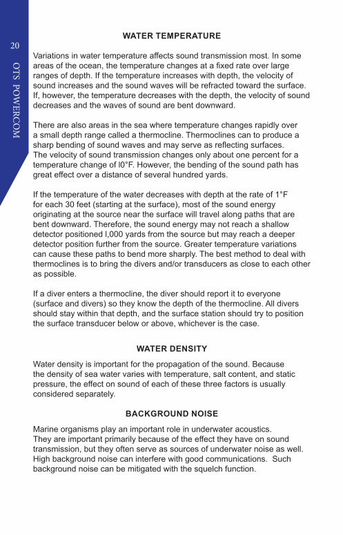
Large natural or man-made objects can block acoustical transmission under certain conditions, in much the same way that a rock blocks a fast-moving current of water. Close to the backside of the rock, in this example, the current is absent and the water seems still. A short distance away, the current is flowing again.
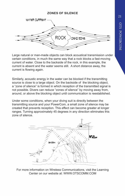
Similarly, acoustic energy in the water can be blocked if the transmitting source is close to a large object. On the backside of the blocking object, a “zone of silence” is formed in which reception of the transmitted signal is not possible. Divers can reduce “zones of silence” by moving away from, around, or above the blocking object until communication is reestablished.
Under some conditions, when your diving suit is directly between the transmitting source and your PowerCom, a small zone of silence may be created that prevents reception. This effect can become greater at longer ranges. Turning approximately 45 degrees in any direction eliminates this zone of silence.
For more information on Wireless Communications, visit the Learning Center on our website at: WWW.OTSCOMM.COM

LIMITED WARRANTY
The Powercom is fully warranted against defects in materials and workmanship, including labor, for a period of one year from the time of purchase. Our obligation under this warranty is limited to the replacing of any part or parts which prove to our satisfaction to have been defective and which have not been misused or carelessly handled.
You must contact an official Ocean Technology Systems (OTS) Service Center or OTS directly to obtain service. If you elect to send the item/s to OTS, you must call and obtain an RMA number from our Repair department. The complete unit and/or damaged part shall be returned to our factory, transportation charges prepaid. We reserve the right to decline responsibility where repairs have been made or attempted by any party other than an OTS service factory trained center or properly trained personnel.
In no event shall OTS be liable for consequential damages related to our product/s.
Warranty registration is required. Any parts requiring replacement due to excessive wear or damage are not covered in this offer. Customer will be notified of any additional charges for worn or damaged components. The customer is responsible for shipping charges to the factory. OTS will pay return shipping limited to the continental United States via UPS Ground service or equivalent for repairs covered by this warranty only. Any other shipping requirements are the responsibility of the customer.
Undersea Systems International, Inc.dba
Ocean Technology Systems3133 West Harvard St., Santa Ana, CA 92704 USA
Telephone: 714.754.7848 Fax: 714.966.1639E-Mail: [email protected]: www.otscomm.com
© Copyright 2020, 2021 by Undersea Systems International, Inc., dba Ocean Technology Systems. All rights reserved. Specifications subject to change without
prior notice.
506283-000 Rev. D