user manual - helix operations
TRANSCRIPT

USER MANUAL Giraffe Tracer
Document number: M000375 Revision: -12Release date: 2020-06-12

USER MANUAL Giraffe Tracer
Rev.: -12 page 2 of 52 M000375
Revision history
Rev. Pages Description Approved by Date
-10 8 19-20
Additional regulator details Relief valve adjustment details.
RF 2020-02-13
-11 8 - 10
14
23
More details for the hook attachment process Additional details for the hook disconnecting process Lubrication comment
RF 2020-04-29
-12 32 - 35 BE390983 Backup Release Harness added, see pos 21
RF 2020-06-12

USER MANUAL Giraffe Tracer
Rev.: -12 page 3 of 52 M000375
Table of Contents 1 INTRODUCTION .................................................................................. 5 2 ATTENTION! ........................................................................................ 5 3 TECHNICAL DATA .............................................................................. 6
3.1 Description .......................................................................................... 6 3.2 Technical specifications ...................................................................... 6
4 OPERATION ........................................................................................ 7 4.1 Before use ........................................................................................... 7 4.2 Preparations ........................................................................................ 8 4.3 Operation ...........................................................................................13 4.4 After use .............................................................................................16 4.5 Filling the bottle with an external diving bottle (workaround) ..............16
5 TRANSPORT ..................................................................................... 18 5.1 On pontoon ........................................................................................18 5.2 Between seat rows .............................................................................19 5.3 On the deck ........................................................................................20
6 INSPECTION AND MAINTENANCE ................................................. 21 6.1 User level ...........................................................................................21 6.2 Maintenance personnel level .............................................................24
7 PARTS LIST ....................................................................................... 28 7.1 Inside .................................................................................................28 7.2 Top section ........................................................................................32 7.3 Middle section ....................................................................................36 7.4 Bottom section ...................................................................................40 7.5 Handlebar and hook ...........................................................................42
8 TOOLS ............................................................................................... 44 8.1 Maintenance Kit .................................................................................44 8.2 Repair Kit ...........................................................................................47
9 ACCESSORIES.................................................................................. 48

USER MANUAL Giraffe Tracer
Rev.: -12 page 4 of 52 M000375
Table of Figures Figure 1: Bottle connection ................................................................................... 7 Figure 2: Hook rope attached ............................................................................... 8 Figure 3: Hook attached properly ......................................................................... 9 Figure 4: Locking ball ..........................................................................................10 Figure 5: Carabiners connected properly ............................................................11 Figure 6: Secured and unsecured carabiners ......................................................12 Figure 7: Preparation ...........................................................................................13 Figure 8: Placing the hook ...................................................................................13 Figure 9: Releasing the hook ...............................................................................14 Figure 10: Retracting the pole .............................................................................15 Figure 11: Filling with an external diving bottle ....................................................16 Figure 12: Relief valve removal ...........................................................................21 Figure 13: Relief valve removal ...........................................................................22 Figure 14: Inside parts 1/2 ...................................................................................28 Figure 15: Inside parts 2/2 ...................................................................................30 Figure 16: Top section parts 1/2 ..........................................................................32 Figure 17: Top section parts 2/2 ..........................................................................34 Figure 18: Middle section parts 1/2 ......................................................................36 Figure 19: Middle section parts 2/2 ......................................................................38 Figure 20: Bottom section parts ...........................................................................40 Figure 21: Handlebar and hook ...........................................................................42

USER MANUAL
Giraffe Tracer
Rev.: -12 page 5 of 52 M000375
1 INTRODUCTION This use- and maintenance manual for this REBS product is prepared by the manufacturer to provide necessary information about the use and maintenance. This REBS product is produced by H. Henriksen AS, in accordance with our SOCES standards. The company and its representatives provide service and training to make sure that your product has a safe and long life. We are all committed to “Reducing Operational Risk”.
2 ATTENTION! This manual and its content should be integrated into formats and systems that your professional unit use. The content of this manual will be given out digitally for free if you contact H. Henriksen AS. Units using this REBS product must do a risk evaluation of the use of the product. Operational scenarios with corresponding risk evaluations must be well known for the operators. Any tampering or modification of the product without the proper authorization from the manufacturer may reduce performance and is done at the sole risk of the user/owner. Incorrect use of the product may cause serious harm or maybe death.

USER MANUAL
Giraffe Tracer
Rev.: -12 page 6 of 52 M000375
3 TECHNICAL DATA
3.1 Description The Giraffe Tracer is a pneumatic powered extension and retraction pole for boarding and entering. The Giraffe Tracer provides an easy to use pneumatic system with push button control for precision up and down movements. The control handle is collapsible and adjustable to retain a slim profile when not in use.
3.2 Technical specifications
Part no. BE003632 BE003345
Description Giraffe Tracer 10 m Giraffe Tracer 15 m
Tracing height 10 m 15 m
Storage height 3,3 m 4,4 m
Weight 10,9 kg 13,5 kg
Full extension time 6 s 8 s
Full retraction time 8 - 11 s 11 - 14 s
Capacity of the BE003431 bottle
Full extension / retraction 10 times
Full extension / retraction 7 times

USER MANUAL
Giraffe Tracer
Rev.: -12 page 7 of 52 M000375
4 OPERATION Important: The pole is designed to place a hook with a ladder on a height. It is NOT designed for climbing. For proper usage and safety reasons we recommend using only original REBS accessories.
4.1 Before use Preparation of the pneumatic system before use:
1. Connect the regulator to the bottle. 2. Connect the regulator to the Giraffe Tracer. 3. Open the valve on the bottle to provide the correct operation
pressure in the system.
Figure 1: Bottle connection
Giraffe Tracer hose
Bottle
Regulator

USER MANUAL
Giraffe Tracer
Rev.: -12 page 8 of 52 M000375
Air regulator: The air regulator is a pressure regulator for use with both 200 and 300 bar bottles. The default setting is approximately 6 - 7,5 bars outlet pressure. This can be adjusted only by a REBS service engineer. This equipment follows the REBS service program: general service and recertification every 2nd year.
4.2 Preparations 1. Connect the second step of the wire ladder to the top mount of
the pole with the backup release harness. Place the harness into the groove on the top mount as illustrated below.
Figure 2: Hook rope attached
Backup release harness placed
Connected to the second step

USER MANUAL
Giraffe Tracer
Rev.: -12 page 9 of 52 M000375
2. Insert the hook into the top mount on the pole. Make sure that the harness remains in the groove of the top mount. The tip of the hook shall point downwards as the harness in the top mount is on the top side.
Figure 3: Hook attached properly
The tip of the hook points downwards.
The harness is on the top side of the top mount

USER MANUAL
Giraffe Tracer
Rev.: -12 page 10 of 52 M000375
There is a spring-loaded locking ball installed in the shaft of the hook. This device locks the hook in the top mount in addition of the magnetic connection at the bottom of the shaft.
Figure 4: Locking ball
It is very important to make sure that the hook is attached in the right way into the top mount (see Figure 3) to ensure the proper locking functionality and to avoid damaging the connected parts.
Bend the hook at the shaft to unload the ball and unlock the hook. Check this function before moving on to the next step!
Locking ball

USER MANUAL
Giraffe Tracer
Rev.: -12 page 11 of 52 M000375
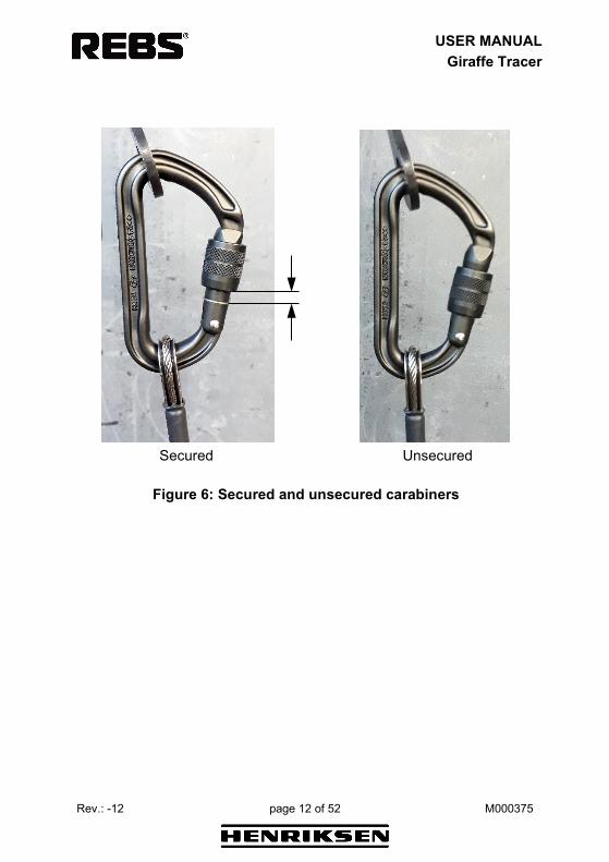
3. Connect the wire ladder to the joints on the hook. Make sure that: - the nut at the joint is not fully tightened and the joints can rotate if they are loaded, - the carabiners are secured, - the carabiners are connected properly - the carabiners are in the correct position as shown below.
Figure 5: Carabiners connected properly
USER MANUAL
Giraffe Tracer
Rev.: -12 page 12 of 52 M000375
Secured Unsecured
Figure 6: Secured and unsecured carabiners

USER MANUAL
Giraffe Tracer
Rev.: -12 page 13 of 52 M000375
4.3 Operation
Figure 7: Preparation
Figure 8: Placing the hook

USER MANUAL
Giraffe Tracer
Rev.: -12 page 14 of 52 M000375
Figure 9: Releasing the hook
Bend the hook at the shaft by pressing the pole against the ledge (see the red arrow at step 2) to unload the locking ball in the shaft. This will release the hook, and now pull the pole with the top mount downwards (retract) to disconnect the hook. If there is not enough pressure in the system to retract the pole properly - pull the wire ladder firmly to disconnect the hook.

USER MANUAL
Giraffe Tracer
Rev.: -12 page 15 of 52 M000375
Figure 10: Retracting the pole

USER MANUAL
Giraffe Tracer
Rev.: -12 page 16 of 52 M000375
4.4 After use Disassembly of the pneumatic system after use:
1. Close the valve on the bottle. NOTE: The system is still under pressure.
2. Press the retract button to release the pressure completely from the system. Check the gauge on the regulator.
3. Disconnect the Giraffe Tracer from the regulator. 4. Disconnect the regulator from the bottle.
4.5 Filling the bottle with an external diving bottle (workaround)
The bottle can be filled with an external diving bottle if necessary. You need the BE004009 Fill line valve v.2 and the BE003752 External air bottle system v.2 to connect the diving cylinder and the bottle. NOTE: A YOKE adapter is needed for the fill line valve in case of 200 bar diving cylinders.
Figure 11: Filling with an external diving bottle
External diving bottle
Fill line valve
Giraffe bottle
External air bottle system

USER MANUAL
Giraffe Tracer
Rev.: -12 page 17 of 52 M000375
Connect and fill: • Connect the bottles • Open the fill line valve: rotate the wheel clockwise. • Open the valve on the Giraffe bottle. • Open the valve on the external bottle to start filling the Giraffe
bottle. Check the gauge on the fill line valve. Disconnect:
• Close the valve on the external diving bottle. • Close the valve on the Giraffe bottle.
NOTE: The system is still under pressure. • Rotate the wheel of the fill line valve slowly counterclockwise to
release the pressurized air from the system completely. Check the gauge on the fill line valve.
• Disconnect the bottles.

USER MANUAL
Giraffe Tracer
Rev.: -12 page 18 of 52 M000375
5 TRANSPORT NOTE: Never transport the pole with hook attached!
5.1 On pontoon
1. The strap keeps the pole from moving sideways.
2. The middle strap keeps the pole from sliding forward.
3. The back strap keeps the pole from moving backwards.

USER MANUAL
Giraffe Tracer
Rev.: -12 page 19 of 52 M000375
5.2 Between seat rows
The base should have an angle so that the pole lies flush on the soft padding. Secure the pole with a Velcro strap or similar
The base has a flexible adapter, so the pole can remain in the base plate ready for immediate use.

USER MANUAL
Giraffe Tracer
Rev.: -12 page 20 of 52 M000375
5.3 On the deck
Use Velcro straps to secure the pole to the three mounting bases.

USER MANUAL
Giraffe Tracer
Rev.: -12 page 21 of 52 M000375
6 INSPECTION AND MAINTENANCE
6.1 User level 6.1.1 Inspection before use The relief valve on the bottom adapter opens when the pole is fully extended, and you keep pushing the UP button 2-3 seconds longer. You can hear when the valve opens and releases the air. The default setting of the relief valve is approximately 1,3 bars. Adjust this setting if the valve opens before the pole is fully extended (see chapter 7.4 on page 40 for part details):
• Remove the relief valve from the bottom sleeve. Use tool BE007064.
Figure 12: Relief valve removal

USER MANUAL
Giraffe Tracer
Rev.: -12 page 22 of 52 M000375
• Use a circlip plier to adjust the valve setting, turning clockwise will increase the opening pressure level:
Figure 13: Relief valve removal
• Mount the valve back into the bottom sleeve and extend the pole
and check the valve function. Please contact the REBS service department if:
• The valve does not open at all • The pressure increases above 2 bars during extending the pole
Do not open the valve, this is a 3rd line maintenance level (only for REBS service engineer).

USER MANUAL
Giraffe Tracer
Rev.: -12 page 23 of 52 M000375
6.1.2 Inspection after use Make sure to inspect the product carefully, after every use. Check that everything works as it should. If you find any problems, please contact your dealer and get the product re-certified. Drops from large heights onto hard surfaces might cause internal and external damage to the structure of the Giraffe Tracer. In such cases, stop using the Giraffe Tracer and contact your dealer for re-qualification.
6.1.3 Cleaning After several uses or after training periods used in saltwater, the Giraffe Tracer and any external equipment should be washed thoroughly in fresh water, and to be disassembled and lubricated before storage.
6.1.4 Lubrication All hinges and moving parts should be lubricated when needed. Use lubricants delivered with the maintenance kit. Lubricate the locking ball at the shaft of the hook (Figure 4).
6.1.5 Disassembly Only to be performed by qualified person.
6.1.6 Storage Both the 10 m and the 15 m pole delivered with a storing bag. The pole should be stored in the bag, or in a dry and dark place, preferably between 15-20˚C. We recommend lubricating all joints prior to storage.

USER MANUAL
Giraffe Tracer
Rev.: -12 page 24 of 52 M000375
6.2 Maintenance personnel level The personnel who is preforming maintenance, and assembling / disassembling the pole, must have the required competence in line with the maintenance procedures. It is required that the maintenance personnel have the required courses from the manufacturer, or/and by own unit. Caution!
• Do not use electric drill/tools! Fasten the bolts by hand with moderate hand force.
• The bolts to the swivel mount and the end bearings are 2 mm longer than the other bolts. It is very important that they are not used on the inside of the collar/end bearings.
• Do not use Loctite products on the bolts.
6.2.1 Correct use of lubricants: • Use Quicksilver Marine Lubricants on all aluminum surfaces that
is in contact with carbon fiber to prevent corrosion between aluminum, stainless steel bolts and carbon fiber.
• Use a thin layer of Super Lube Teflon oil on carbon fiber surfaces (pole) inside and outside.
• Molykote 111 is only to be used on O-rings. • CRC 5-56 is to be used on nylon rolls to dissolve dirt.

USER MANUAL
Giraffe Tracer
Rev.: -12 page 25 of 52 M000375
6.2.2 Daily maintenance Maintenance tasks after use in seawater:
• Disconnect the high-pressure coupling. • Take of the end bearings, (3x) M4 x 8 mm bolts. • Remove the relief valve (without adjusting or taking it apart) with
the spark plug wrench. Put the relief valve into freshwater bath. • Wash the inside of the pole with freshwater. Place the pole so
that the lowest point is the hook coupling and wash it with fresh water 2-3 times.
• Extend the pole, section by section with the end bearings dismounted, and wash each section thoroughly on the outside with fresh water.
• Dry off each section on the outside with a clean cloth. • Inspect the pole for damage and deformation. Check the
guidance grooves, end bearings (collars) and the bolts to the swivel mount. (Experience shows that the bolts used in the collars can loosen during transport. Do not use Loctite!)
• Blow the pole dry with pressurized air and store the pole vertical until it is completely dry.
• Add a thin layer Quicksilver Marine Lubricants (grease) on the end bearings and then assemble the end bearings. Push the end bearings gently on, until the holes are in line. Use the guiding pin to verify the lining of the holes.
• Use new bolts and screw every bolt halfway in before tightening the bolts with moderate hand force.
• Change the bolts on the outside of the collar only! • Apply a thin layer of Super Lube Teflon oil on tubes.

USER MANUAL
Giraffe Tracer
Rev.: -12 page 26 of 52 M000375
6.2.3 Periodic maintenance Periodic maintenance tasks after prolonged use or before the equipment is stored: The end bearings between the collars only have one small hole that will hamper the lavage of seawater. Experience from usage shows that prolonged use increases the risk of corrosion inside the collars produced in aluminum. It is therefore necessary to disassemble and lubricate the equipment immediately after use. After assembly, do a test of the poles. Extend and retract 1-2 times with air before storing.
• Disconnect the high-pressure coupling. • Disconnect the top mount assembly. • Remove the bottom sleeve assembly. • Remove the relief valve (without adjusting or taking it apart) with
the spark plug wrench. Put the relief valve into freshwater bath. • Disassemble the end bearings, (3x) M4 x 6 mm bolts. • Disassemble all three sections, a total of 3x3 M4 x 6 mm external
and internal bolts. • Pull out the thickest pole first. • Place the parts in a bucket of lukewarm freshwater. • Inspect the end bearings (collars) with nylon rolls for damage.
Blow them dry with pressurized air, spray with CRC 5-56 spray. • Wash the pole sections both inside and outside with freshwater. • Dry off the pole sections outside with a clean and dry cloth, and
at the same time, inspect the poles for damage or deformation. Especially check the guiding grooves.
• Blow the inside of the poles dry with pressurized air. • Use a lace which is longer than the pole lengths, attach a paint
roller and attach x-number of cloths until the correct friction is achieved. Blow the lace through the pole with a high-pressure air-gun. Repeat the process 2-3 times on each pole section.
• Change cloth and add Super Lube Teflon oil on it. Pull the cloth through all sections.

USER MANUAL
Giraffe Tracer
Rev.: -12 page 27 of 52 M000375
• Add a thin layer of Super Lube Teflon oil on the outside of the pole, and clean/wipe the outside of the pole completely dry.
• Inspect the inside of the pole. Look for damage, marks and foreign objects.
• Inspect and lubricate the O-rings with Molykote 111. Replace the O-rings if they appear to be damaged.
• Assemble the poles. The guidance grooves must point to the guidance unit.
• Use new bolts (M4 x 6 mm) to attach the 3 internal collars. • Always test (extend) manually - without the relief valve - that the
sections are correctly assembled before testing with pressurized air. This to ensure that the guiding is working properly and that the poles are correctly assembled.
• Assure that the hook attachment is in line relative to the guidance unit. Use new bolt (M4 x 8 mm) when assembling.
• Add a thin layer of Quicksilver Marine Lubricants on the top mount assembly and the bottom sleeve assembly.
• Mount the end section. Push the outside bearings gently in until the holes are in line. Use the guiding pin to align the holes.
• Screw all bolts (M4 x 8 mm) halfway in before tightening with moderate hand force.
USER MANUAL
Giraffe Tracer
Rev.: -12 page 28 of 52 M000375
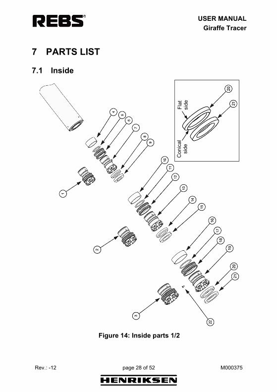
7 PARTS LIST
7.1 Inside
Figure 14: Inside parts 1/2
Flat
si
de
Con
ical
si
de

USER MANUAL
Giraffe Tracer
Rev.: -12 page 29 of 52 M000375
3rd
line X X X X X X X X X X X
1st l
ine:
Use
r on
the
field
2n
d lin
e: T
echn
icia
n at
the
wor
ksho
p 3r
d lin
e: S
peci
alis
t cer
tifie
d by
H. H
enrik
sen
AS
or a
t H. H
enrik
sen
AS
2nd
line X X X
1st
line
Des
crip
tion
Insi
de E
nd B
earin
g C
olla
r Ass
y.1
- PEE
K
Insi
de E
nd B
earin
g C
olla
r Ass
y.2
- PEE
K In
side
End
Bea
ring
Col
lar A
ssy.
3 - P
EEK
Stop
Col
lar 1
O-ri
ng 3
1,5
x 3
Tube
Sea
ls 1
Inne
r End
Bea
ring
Col
lar 1
- PE
EK
Dam
ping
Rin
g 1
Botto
m D
ampe
r 1
Stop
Col
lar 2
O-ri
ng 3
9,2
x 3
Tube
Sea
ls 2
Inne
r End
Bea
ring
Col
lar 2
- PE
EK
Dam
ping
Rin
g 2
Qty
.
1 1 1 1 2 2 1 1 1 1 2 2 1 1
Part
No.
BE00
6370
BE00
6371
BE
0063
72
BE00
6380
BE21
6382
BE
0063
83
BE00
6462
BE00
6385
BE
0063
86
BE00
6387
BE21
6388
BE
0063
89
BE00
6463
BE00
6391
Item
no
.
1 2 3 4 5 6 7 8 9 10
11
12
13
14

USER MANUAL
Giraffe Tracer
Rev.: -12 page 30 of 52 M000375
Figure 15: Inside parts 2/2
Flat
si
de
Con
ical
si
de
USER MANUAL
Giraffe Tracer
Rev.: -12 page 31 of 52 M000375
3rd
line X X X X X X X
1st l
ine:
Use
r on
the
field
2n
d lin
e: T
echn
icia
n at
the
wor
ksho
p 3r
d lin
e: S
peci
alis
t cer
tifie
d by
H. H
enrik
sen
AS
or a
t H. H
enrik
sen
AS
2nd
line X
1st
line
Des
crip
tion
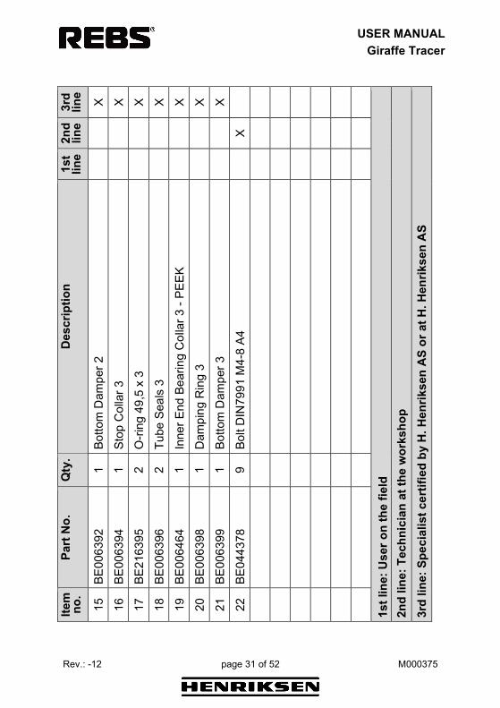
Botto
m D
ampe
r 2
Stop
Col
lar 3
O
-ring
49,
5 x
3
Tube
Sea
ls 3
Inne
r End
Bea
ring
Col
lar 3
- PE
EK
Dam
ping
Rin
g 3
Botto
m D
ampe
r 3
Bolt
DIN
7991
M4-
8 A4
Qty
.
1 1 2 2 1 1 1 9
Part
No.
BE00
6392
BE00
6394
BE
2163
95
BE00
6396
BE00
6464
BE
0063
98
BE00
6399
BE04
4378
Item
no
.
15
16
17
18
19
20
21
22
USER MANUAL
Giraffe Tracer
Rev.: -12 page 32 of 52 M000375
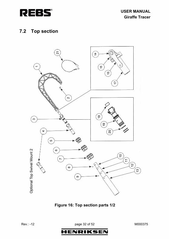
7.2 Top section
Figure 16: Top section parts 1/2

USER MANUAL
Giraffe Tracer
Rev.: -12 page 33 of 52 M000375
3rd
line X X X X
1st l
ine:
Use
r on
the
field
2n
d lin
e: T
echn
icia
n at
the
wor
ksho
p 3r
d lin
e: S
peci
alis
t cer
tifie
d by
H. H
enrik
sen
AS
or a
t H. H
enrik
sen
AS
2nd
line X X X X X X X X
1st
line X
Des
crip
tion
Gira
ffe H
ook
with
out A
4 pi
g
Hoo
k Ti
p To
p m
ount
ass
embl
y
Top
Swiv
el M
ount
2 (o
ptio
nal)
Out
er E
nd B
earin
g C
olla
r 1 A
ssy.
- PE
EK
Out
er E
nd B
earin
g C
olla
r 2 A
ssy.
- PE
EK
Out
er E
nd B
earin
g C
olla
r 3 A
ssy.
- PE
EK
Bolt
DIN
7985
M4-
8 A4
TR
X Sc
rew
DIN
7985
M4-
6 A4
TR
X
Car
bon
Tube
1 -
10m
Car
bon
Tube
1 -
15m
C
arbo
n Tu
be 2
- 10
m
Car
bon
Tube
2 -
15m
Qty
.
1 1 1 1 1 1 1 3 9 1 1 1 1
Part
No.
BE00
6451
BE00
6401
BE
0002
25
BE00
6422
BE00
6373
BE
0063
74
BE00
6375
BE00
6405
BE
0064
06
BE00
6407
BE00
6408
BE
0064
09
BE00
6410
Item
no
.
1 2 3 4 5 6 7 8 9 10
10
11
11

USER MANUAL
Giraffe Tracer
Rev.: -12 page 34 of 52 M000375
Figure 17: Top section parts 2/2

USER MANUAL
Giraffe Tracer
Rev.: -12 page 35 of 52 M000375
3rd
line X X X X
1st l
ine:
Use
r on
the
field
2n
d lin
e: T
echn
icia
n at
the
wor
ksho
p 3r
d lin
e: S
peci
alis
t cer
tifie
d by
H. H
enrik
sen
AS
or a
t H. H
enrik
sen
AS
2nd
line X X X
1st
line X X X X X
Des
crip
tion
Car
bon
Tube
3 -
10m
Car
bon
Tube
3 -
15m
C
arbo
n Tu
be 4
- 10
m
Car
bon
Tube
4 -
15m
Bolt
with
nut
/was
hers
H
ook/
ladd
er jo
int (
1 se
t of 2
pcs
)
Hoo
k sp
ring
REL
EASE
MAL
E AS
SY
Top
mou
nt m
agne
t
Top
Mou
nt
O-ri
ng 2
8 x
3 N
BR90
Ba
ckup
Rel
ease
Har
ness
Qty
.
1 1 1 1 1 2 1 1 1 1 3 1
Part
No.
BE00
6411
BE00
6412
BE
0064
13
BE00
6414
BE00
7547
BE
0075
48
BE00
7549
BE00
7550
BE
3900
87
BE39
0086
BE39
0088
BE
3909
83
Item
no
.
12
12
13
13
14
15
16
17
18
19
20
21

USER MANUAL
Giraffe Tracer
Rev.: -12 page 36 of 52 M000375
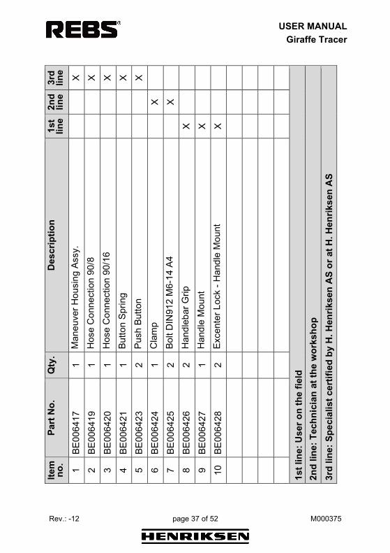
7.3 Middle section
Figure 18: Middle section parts 1/2
4
16
1817
USER MANUAL
Giraffe Tracer
Rev.: -12 page 37 of 52 M000375
3rd
line X X X X X
1st l
ine:
Use
r on
the
field
2n
d lin
e: T
echn
icia
n at
the
wor
ksho
p 3r
d lin
e: S
peci
alis
t cer
tifie
d by
H. H
enrik
sen
AS
or a
t H. H
enrik
sen
AS
2nd
line X X
1st
line X X X
Des
crip
tion
Man
euve
r Hou
sing
Ass
y.
Hos
e C
onne
ctio
n 90
/8
Hos
e C
onne
ctio
n 90
/16
Butto
n Sp
ring
Push
But
ton
Cla
mp
Bolt
DIN
912
M6-
14 A
4
Han
dleb
ar G
rip
Han
dle
Mou
nt
Exce
nter
Loc
k - H
andl
e M
ount
Qty
.
1 1 1 1 2 1 2 2 1 2
Part
No.
BE00
6417
BE
0064
19
BE00
6420
BE00
6421
BE
0064
23
BE00
6424
BE00
6425
BE
0064
26
BE00
6427
BE00
6428
Item
no
. 1 2 3 4 5 6 7 8 9 10

USER MANUAL
Giraffe Tracer
Rev.: -12 page 38 of 52 M000375
Figure 19: Middle section parts 2/2
4
16
1817

USER MANUAL
Giraffe Tracer
Rev.: -12 page 39 of 52 M000375
3rd
line
1st l
ine:
Use
r on
the
field
2n
d lin
e: T
echn
icia
n at
the
wor
ksho
p 3r
d lin
e: S
peci
alis
t cer
tifie
d by
H. H
enrik
sen
AS
or a
t H. H
enrik
sen
AS
2nd
line X X
1st
line X X X X X X
Des
crip
tion
Bolt
ISO
738
0 M
8-40
A4
Was
her D
IN12
5A M
8 A4
H
andl
e Sp
ring
Han
dleb
ar T
ube
Exce
ntre
Loc
k - H
andl
ebar
H
exag
on S
crew
DIN
912
M6x
50 A
4 D
own
Butto
n C
ompl
ete
Up
Butto
n C
ompl
ete
Qty
.
2 2 1 1 2 1 1 1
Part
No.
BE00
6429
SR
8233
20
BE00
6431
BE
0064
32
BE00
6433
BE
0064
34
BE00
6460
BE
0064
61
Item
no
. 11
12
13
14
15
16
17
18

USER MANUAL
Giraffe Tracer
Rev.: -12 page 40 of 52 M000375
7.4 Bottom section
Figure 20: Bottom section parts

USER MANUAL
Giraffe Tracer
Rev.: -12 page 41 of 52 M000375
3rd
line
1st l
ine:
Use
r on
the
field
2n
d lin
e: T
echn
icia
n at
the
wor
ksho
p 3r
d lin
e: S
peci
alis
t cer
tifie
d by
H. H
enrik
sen
AS
or a
t H. H
enrik
sen
AS
2nd
line X X X X X X X X X X
1st
line
Des
crip
tion
Inle
t Hos
e - 8
99 *
Out
let H
ose
- 16
Hos
e H
olde
r
Hos
e C
onne
ctio
n 90
/16
Hos
e C
onne
ctio
n 0/
8 O
-ring
Nitr
ile
Bolt
DIN
7985
M4-
8 A4
TR
X
Botto
m S
leev
e R
elie
f Val
ve
Botto
m S
leev
e As
sy.
Gira
ffe A
ir Su
pply
Hos
e
Incl
udin
g: B
E006
435
+ BE
0064
39 +
BE0
0641
9
Qty
.
1 1 3 1 1 2 3 1 1 1
Part
No.
BE00
6435
BE00
6436
BE
0064
37
BE00
6438
BE00
6439
BE
2164
42
BE00
6405
BE00
6441
BE
0064
43
BE00
6444
BE39
0266
Item
no
.
1 2 3 4 5 6 7 8 9 10 *

USER MANUAL
Giraffe Tracer
Rev.: -12 page 42 of 52 M000375
7.5 Handlebar and hook
Figure 21: Handlebar and hook
1
2

USER MANUAL
Giraffe Tracer
Rev.: -12 page 43 of 52 M000375
3rd
line
1st l
ine:
Use
r on
the
field
2nd
line:
Tec
hnic
ian
at th
e w
orks
hop
3rd
line:
Spe
cial
ist c
ertif
ied
by H
. Hen
rikse
n A
S or
at H
. Hen
rikse
n A
S
2nd
line
1st
line X X
Des
crip
tion
Gira
ffe c
ompl
ete
hand
leba
r
Gira
ffe re
leas
e m
echa
nism
with
hoo
k
Qty
.
1 1
Part
No.
BE00
6452
BE00
3346
Item
no
. 1 2

USER MANUAL
Giraffe Tracer
Rev.: -12 page 44 of 52 M000375
8 TOOLS
8.1 Maintenance Kit The BE008068 Giraffe Tracer Maintenance Kit contains the following tools and consumables:
BE000095 Screwdriver T20 TORX
BE000096 Screwdriver PZ2 STAR
BE000093 Allen key 2,5 mm
BE004880 Allen key 3,0 mm
BE000094 Allen key 4,0 mm
BE110050 Plastic wedge
BE110090 Brush flat 10 mm

USER MANUAL
Giraffe Tracer
Rev.: -12 page 45 of 52 M000375
BE000098 Guiding pin tool
BE110085 Guiding tool for gasket rings
BE007064 Spark plug wrench 25 - 28 mm
BE000097 Plastic / rubber hammer
BE145603 Lace polyester black 4 m / 3 mm
BE110089 Sponge 200x125x60

USER MANUAL
Giraffe Tracer
Rev.: -12 page 46 of 52 M000375
BE005064 MOLYKOTE 111-10G
BE110086 Quicksilver Anti-Corrosion Marine Lubricant
BE110087 Super Lube - Synthetic lubricant Syncolon (PTFE)
BE127026 Bag

USER MANUAL
Giraffe Tracer
Rev.: -12 page 47 of 52 M000375
8.2 Repair Kit There are three types of repair kits available:
• BE008085 Giraffe Tracer Repair Kit: o 1 x BE118089 Carbon fiber tube ø40xø37ø300 o 1 x BE118088 Damping ring, flat o 1 x BE118087 Damping ring o 1 x BE118092 Marking jig o 1 x BE118091 Top sleeve o 1 x BE390268 Drill 4,1 mm o 1 x M000376 Manual
• BE008097 Giraffe Tracer Handlebar Repair Kit Type A:
o 1 x BE118101 Handlebar clamp o 1 x BE006431 Handle spring o 1 x BE110198 Handlebar plate Type A o 1 x BE390267 Drill 5,0 mm o 1 x BE390268 Drill 4,1 mm o 4 x SR942599 DIN 912 M5-16 A4 o 8 x SR824001 DIN 125A M5 A4 o 4 x SR816261 DIN 9021 M5 A4 o 1 x M000377 Manual
• BE157991 Giraffe Tracer Handlebar Repair Kit Type B:
o 1 x BE006431 Handle spring o 1 x BE006428 Excenter Lock - Handle Mount o 1 x BE207832 Steel reinforcement for Giraffe handle o 1 x BE390267 Drill 5,0 mm o 1 x BE390268 Drill 4,1 mm o 4 x SR944622 DIN 912 M5-12 A4 o 1 x SR942669 DIN 912 M6-50 A4 o 1 x SR624002 DIN 934 M6 A4 o 4 x SR824001 DIN 125A M5 A4 o 1 x M000377 Manual
Please contact your dealer for more information.

USER MANUAL
Giraffe Tracer
Rev.: -12 page 48 of 52 M000375
9 ACCESSORIES The Giraffe Tracer can be combined with a wide variety of Henriksen products: wire ladders, rope ladders, etc. Please refer to the latest REBS catalogue for our soft ladder assortment.
BE003431 Air bottle
BE003352 Air regulator
BE003361 Complete baseplate 200 x 200 BE006132 Complete baseplate 490 x 490

USER MANUAL
Giraffe Tracer
Rev.: -12 page 49 of 52 M000375
BE003349 Transportation bag
BE004009 Fill line valve v.2
BE003752 External air bottle system v.2

USER MANUAL
Giraffe Tracer
Rev.: -12 page 50 of 52 M000375
Notes

USER MANUAL
Giraffe Tracer
Rev.: -12 page 51 of 52 M000375
Notes

Rapid Entering and Boarding Systems
H. Henriksen AS Træleborgveien 15
3112 Tønsberg NORWAY
www.hhenriksen.com