user manual dsl-2750u
DESCRIPTION
ManualsTRANSCRIPT
DSL-2750U/TK
User Manual
DSL-2750U User Manual
ii
Contents
1 Safety Precautions ............................................................................................. 1 2 Introduction ........................................................................................................ 2
2.1 Packing List ........................................................................................... 2 2.2 LEDs and Interfaces.............................................................................. 2 2.3 System Requirements ........................................................................... 6 2.4 Features ................................................................................................ 6
3 Hardware Installation ......................................................................................... 7 3.1 Choosing the Best Location for Wireless Operation.............................. 7 3.2 Connecting the Router........................................................................... 7
4 About the Web Configurator............................................................................... 8 4.1 Access the Router ................................................................................. 8 4.2 Setup ................................................................................................... 10
4.2.1 Wizard....................................................................................... 10 4.2.2 Internet Setup ........................................................................... 17 4.2.3 3G Internet Setup ..................................................................... 25 4.2.4 Wireless Connection................................................................. 28 4.2.5 Local Network ........................................................................... 32 4.2.6 Time and Date .......................................................................... 35 4.2.7 Print Server............................................................................... 36 4.2.8 Logout....................................................................................... 37
4.3 Advanced............................................................................................. 38 4.3.1 Wireless Settings...................................................................... 38 4.3.2 Port Forwarding ........................................................................ 45 4.3.3 Port Triggering .......................................................................... 48 4.3.4 DMZ.......................................................................................... 50 4.3.5 Parental Control........................................................................ 51 4.3.6 Filtering Options........................................................................ 55 4.3.7 DNS .......................................................................................... 61 4.3.8 Dynamic DNS ........................................................................... 62 4.3.9 Storage Service ........................................................................ 64 4.3.10 Multicast .............................................................................. 66 4.3.11 Network Tools...................................................................... 67 4.3.12 Routing ................................................................................ 79
DSL-2750U User Manual
iii
4.3.13 Schedules............................................................................ 83 4.3.14 Logout ................................................................................. 84
4.4 Maintenance ........................................................................................ 84 4.4.1 System...................................................................................... 84 4.4.2 Firmware Update ...................................................................... 86 4.4.3 Access Controls........................................................................ 86 4.4.4 Diagnostics ............................................................................... 90 4.4.5 System Log............................................................................... 91 4.4.6 Logout....................................................................................... 93
4.5 Status................................................................................................... 93 4.5.1 Device Info................................................................................ 93 4.5.2 Wireless Clients ........................................................................ 95 4.5.3 DHCP Clients............................................................................ 95 4.5.4 Logs .......................................................................................... 95 4.5.5 Statistics.................................................................................... 96 4.5.6 Route info ................................................................................. 98 4.5.7 Logout....................................................................................... 98
5 FAQs ................................................................................................................ 99 6 Support........................................................................................................... 100
ADSL Support: ............................................................................................... 100 Telephone: 10210................................................................................. 100
Router Support: ............................................................................................. 100 Telephone: 0860 343578 (0860 2 HELP U) ......................................... 100
DSL-2750U User Manual
1
1 Safety Precautions
Follow the instructions below to prevent damage to the device and the risk of fire or
electric shock:
Use the power adapter supplied with the unit and plug it into a suitably rated
power outlet.
Leave sufficient space around the Power adapter and Modem to allow the
free flow of air for heat dissipation. Do not cover the device ventilation slots
as this will result in the device overheating.
Do not install this device close to a heat source or in an area of high
temperature. Avoid exposure to direct sunlight.
Do not install in a damp environment or allow fluid to spill on the Modem or
Power Supply.
Only connect this device as specified in the Manual or installation Wizard.
Failure to observe these instructions can lead to the risk of fire or damage to
the equipment concerned.
Install in a well-ventilated dry environment on a stable surface.
DSL-2750U User Manual
2
2 Introduction
The DSL-2750U is a highly integrated ADSL2/2+ Internet Access Device. It
provides ADSL connectivity, optional 3G connectivity via USB port, Ethernet LAN
and Wireless LAN services. The wireless LAN complies with the IEEE802.11b/g/n
standards and supports 2T2R. It is used to provide high performance internet
access for individual and SOHO users.
2.1 Packing List
1 x DSL-2750U Router
1 x 3-Pin Power Supply / Lightning Protection Unit
1 x Splitter
1 x Micro Filter
1 x Installation CD
2 x RJ11 Phone Cables (one is Red, one is Grey)
1 x RJ45 Ethernet cable (Yellow)
Documents
2.2 LEDs and Interfaces
Note:
The figures in this document are for reference only.
DSL-2750U User Manual
3
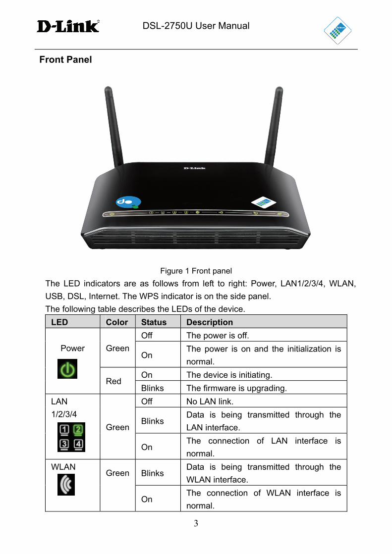
Front Panel
Figure 1 Front panel
The LED indicators are as follows from left to right: Power, LAN1/2/3/4, WLAN,
USB, DSL, Internet. The WPS indicator is on the side panel.
The following table describes the LEDs of the device.
LED Color Status Description
Off The power is off.
Green On
The power is on and the initialization is
normal.
On The device is initiating.
Power
Red Blinks The firmware is upgrading.
Off No LAN link.
Blinks Data is being transmitted through the
LAN interface.
LAN
1/2/3/4
Green
On The connection of LAN interface is
normal.
Blinks Data is being transmitted through the
WLAN interface.
WLAN Green
On The connection of WLAN interface is
normal.
DSL-2750U User Manual
4
LED Color Status Description
Off The WLAN connection is not established.
On The connection of 3G or USB flash disk
has been established.
Blink Data is being transmitted.
USB
Green
Off No signal is detected.
Off Initial self-test failed.
Blinks The device is negotiating the best speed
on the DSL line.
DSL
Green
On DSL connection has been established.
Off
The device is in Bridge mode, DSL
connection is not present, or the power is
off. Green
On IP is connected and no traffic is detected.
Internet
Red On The device attempted an IP connection,
but failed.
Blinks WPS negotiation is enabled, waiting for
wireless clients.
WPS (on
the side
panel) Green
Off Device is ready for new WPS to setup.
DSL-2750U User Manual
5
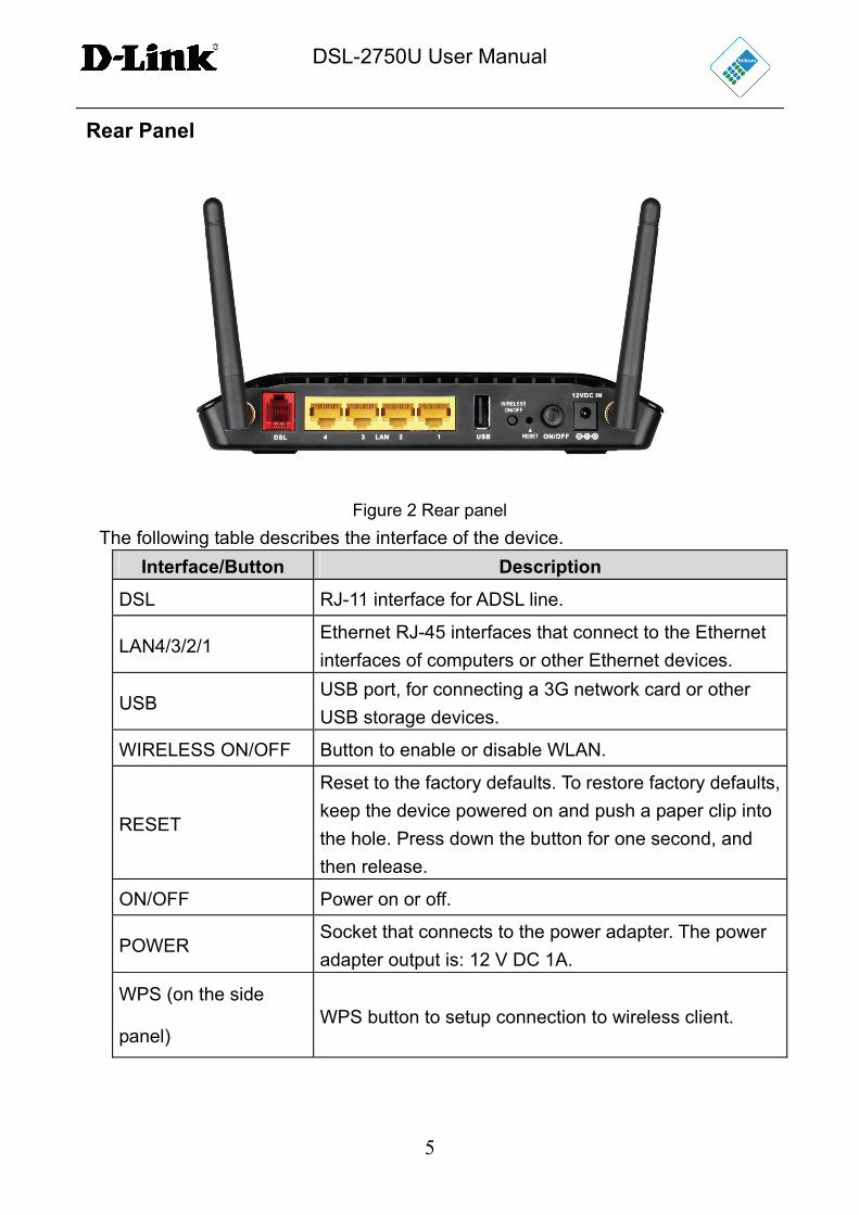
Rear Panel
Figure 2 Rear panel
The following table describes the interface of the device.
Interface/Button Description
DSL RJ-11 interface for ADSL line.
LAN4/3/2/1 Ethernet RJ-45 interfaces that connect to the Ethernet
interfaces of computers or other Ethernet devices.
USB USB port, for connecting a 3G network card or other
USB storage devices.
WIRELESS ON/OFF Button to enable or disable WLAN.
RESET
Reset to the factory defaults. To restore factory defaults,
keep the device powered on and push a paper clip into
the hole. Press down the button for one second, and
then release.
ON/OFF Power on or off.
POWER Socket that connects to the power adapter. The power
adapter output is: 12 V DC 1A.
WPS (on the side
panel) WPS button to setup connection to wireless client.
DSL-2750U User Manual
6
2.3 System Requirements
Recommended system requirements are as follows:
A 10/100BaseT Ethernet card or wireless adapter is installed on your PC
Operating system: Windows 98SE, Windows 2000, Windows ME, Windows
XP, Windows Vista or Windows 7
Internet Explorer V5.0 or higher, Netscape V4.0 or higher, or Firefox 1.5 or
higher
2.4 Features
The device supports the following features:
User-friendly GUI for web configuration
Compatible with all standard Internet applications
Industry standard and interoperable DSL interface
Simple web-based status page displays a snapshot of system configuration,
and links to the configuration pages
Downloadable flash software updates
WLAN with high-speed data transfer rates of up to 300 Mbps, compatible
with IEEE 802.11b/g/n, 2.4GHz compliant equipment
IP routing and bridging
Asynchronous Transfer Mode (ATM) and Digital Subscriber Line (DSL)
support
Point-to-Point Protocol (PPP)
Network/Port Address Translation (NAT/PAT)
Quality of Service (QoS)
Wireless LAN security: WPA, 802.1x, RADIUS client
Universal Plug-and-Play (UPnP)
Print server
Web filtering
3G Mobile WAN connection
USB mass-storage, SAMBA
System statistics and monitoring
DSL-2750U User Manual
7
3 Hardware Installation
3.1 Choosing the Best Location for Wireless Operation
Many environmental factors may affect the effective wireless function of the DSL
Router. If this is the first time that you are setting up a wireless network device,
read the following information:
The access point can be placed on a shelf or desktop, ideally you should be able to
see the LED indicators in the front, as you may need to view them for
troubleshooting.
Designed to go up to 100 meters indoors and up to 300 meters outdoors, wireless
LAN lets you access your network from anywhere you want. However, the number
of walls, ceilings, or other objects that the wireless signals must pass through limit
signal range. Typical ranges vary depending on types of materials and background
RF noise in your home or business.
3.2 Connecting the Router
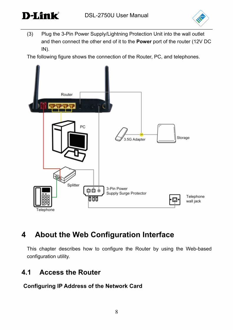
(1) Connect the DSL port of the router and the port marked (Red, DSL) on the
splitter with the (Red) telephone cable; connect the phone to the port of the
splitter marked (Green, Phone) using the cable provided with the telephone,
and connect the short (line) cable of the splitter to the (OUT) socket of the
3-Pin Power Supply/Lightning Protection unit. Connect the telephone wall
socket to the (IN) socket on the 3-Pin Power Supply/Lightning protection
unit.
The splitter has three ports:
LINE: Connect to (OUT) port on 3-Pin Power Supply/Lightning
Protection Unit
DSL: Connect to the DSL interface of the router using the red cable
provided
PHONE: Connect to a telephone set using the cable provided with the
telephone
(2) Connect the LAN port of the router to the network interface card (NIC) of the
PC using the (Yellow) Ethernet cable provided.
DSL-2750U User Manual
8
(3) Plug the 3-Pin Power Supply/Lightning Protection Unit into the wall outlet
and then connect the other end of it to the Power port of the router (12V DC
IN).
The following figure shows the connection of the Router, PC, and telephones.
4 About the Web Configuration Interface
This chapter describes how to configure the Router by using the Web-based
configuration utility.
4.1 Access the Router
Configuring IP Address of the Network Card
DSL-2750U User Manual
9
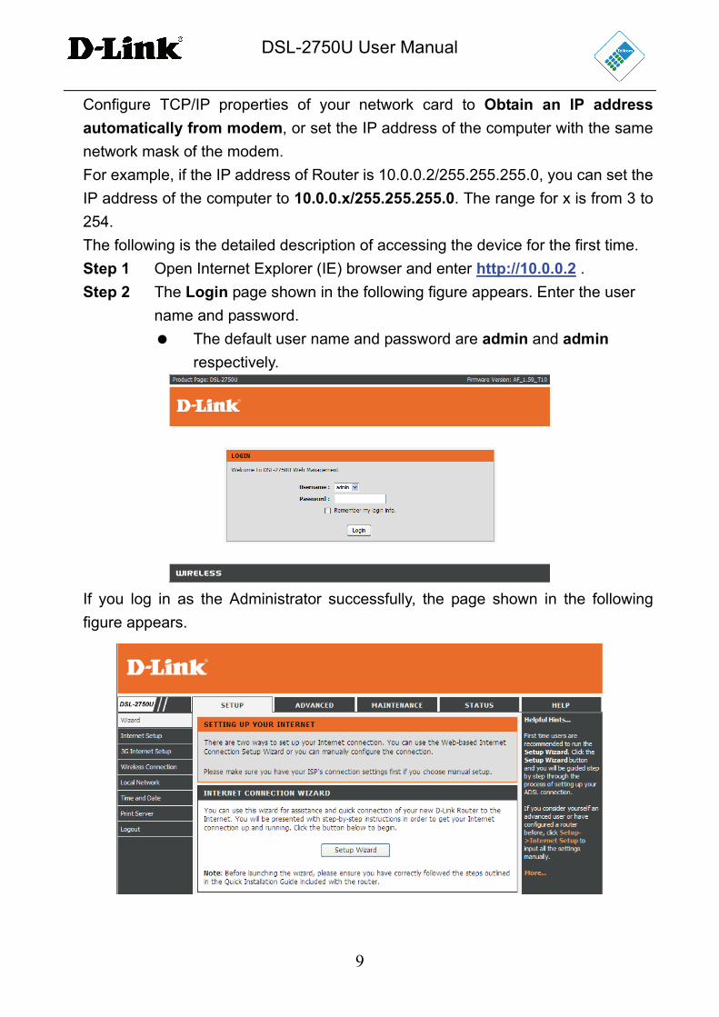
Configure TCP/IP properties of your network card to Obtain an IP address
automatically from modem, or set the IP address of the computer with the same
network mask of the modem.
For example, if the IP address of Router is 10.0.0.2/255.255.255.0, you can set the
IP address of the computer to 10.0.0.x/255.255.255.0. The range for x is from 3 to
254.
The following is the detailed description of accessing the device for the first time.
Step 1 Open Internet Explorer (IE) browser and enter http://10.0.0.2 .
Step 2 The Login page shown in the following figure appears. Enter the user
name and password.
The default user name and password are admin and admin
respectively.
If you log in as the Administrator successfully, the page shown in the following
figure appears.

DSL-2750U User Manual
10
If the login information is incorrect, click Try Again in the page that pops up to log
in again.
4.2 Setup
4.2.1 Wizard
Wizard enables fast and accurate configuration of the Internet connection and
other important parameters. The following sections describe these various
configuration parameters.
When subscribing to a broadband service, you should be aware of the method by
which you are connected to the Internet. Your physical WAN device can be
Ethernet, DSL, or both. Technical information about the properties of your Internet
connection are provided by your Internet Service Provider (ISP). For example, your
ISP should inform you whether you are connected to the Internet using a static or
dynamic IP address, or the protocol, such as PPPoA or PPPoE, that you use to
communicate over the Internet.
Step 1 Choose Setup > Wizard. The page shown in the following figure
appears.
DSL-2750U User Manual
11
Step 2 Click Setup Wizard. The page shown in the following figure appears.
Step 3 There are five steps to configure the device. Click Next to continue.
Step 4 Change Device Login Password.
The default password of admin account is "admin". In order to secure your network,
please modify the password. Note: Confirm Password must be the same as "New
Password". Of course, you can click Skip to ignore the step and keep the default
password.
DSL-2750U User Manual
12
Step 5 Set time and date.
Step 6 Configure the Internet connection.
Select the country and ISP. The default settings for the ISP will appear. If
you fail to find the country and ISP from the drop-down lists, select
Others, and set the VPI and VCI. Click Next. If the Protocol is PPPoE
or PPPoA, the following page appears.
DSL-2750U User Manual
13
In this page, enter the user name and password provided by your ISP.
If the Protocol is Dynamic IP or Bridge, the page shown in the following figure
appears.
DSL-2750U User Manual
14
If the Protocol is Static IP, the page shown in the following figure appears.
Enter the IP Address, Subnet Mask, Default Gateway, and Primary DNS Server.
Click Next. The page shown in the following page appears.
DSL-2750U User Manual
15
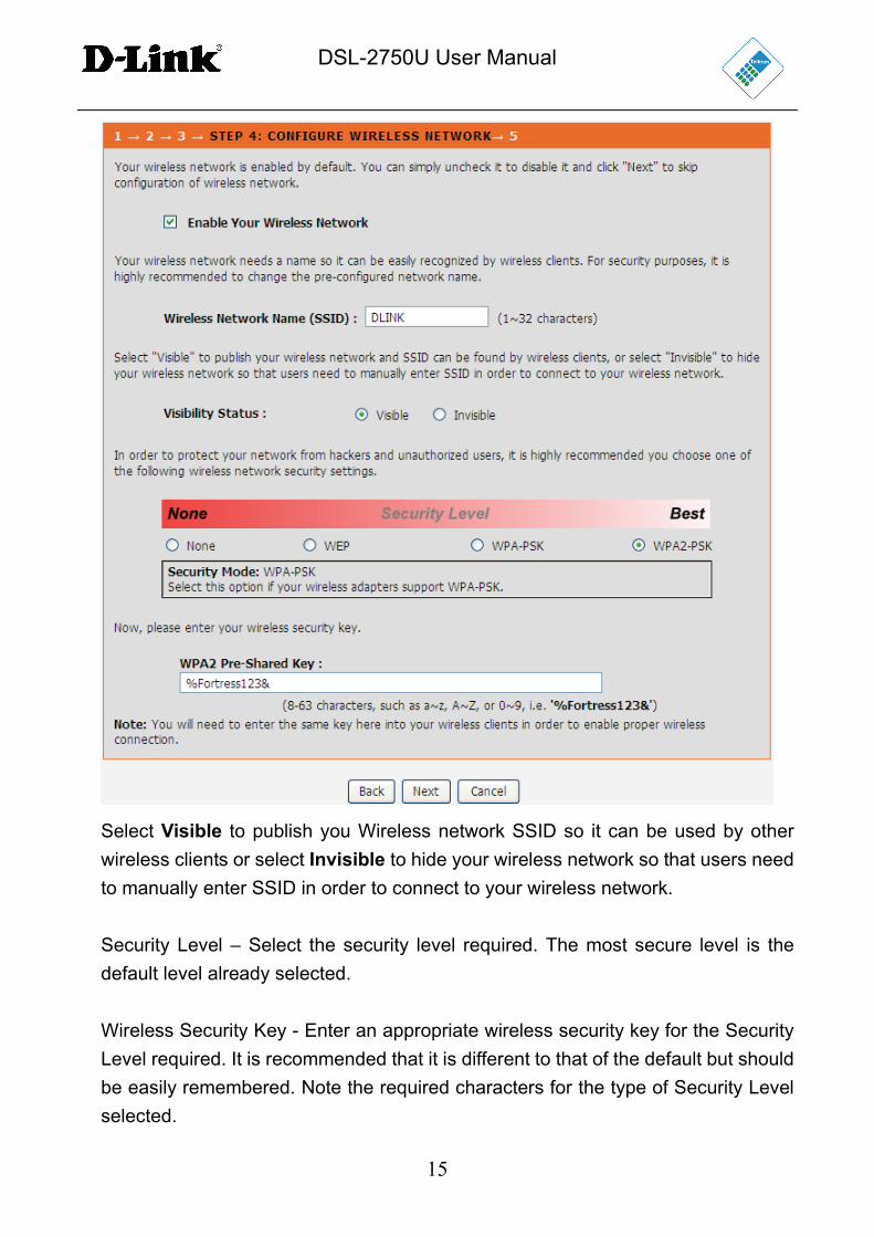
Select Visible to publish you Wireless network SSID so it can be used by other
wireless clients or select Invisible to hide your wireless network so that users need
to manually enter SSID in order to connect to your wireless network.
Security Level – Select the security level required. The most secure level is the
default level already selected.
Wireless Security Key - Enter an appropriate wireless security key for the Security
Level required. It is recommended that it is different to that of the default but should
be easily remembered. Note the required characters for the type of Security Level
selected.
DSL-2750U User Manual
16
Note: You will need to enter the same key here into your wireless clients in order to enable proper wireless connection.
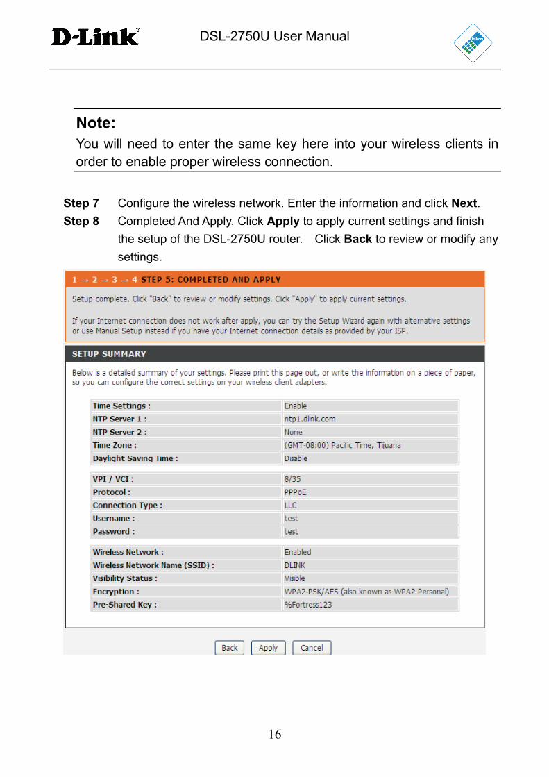
Step 7 Configure the wireless network. Enter the information and click Next.
Step 8 Completed And Apply. Click Apply to apply current settings and finish
the setup of the DSL-2750U router. Click Back to review or modify any
settings.
DSL-2750U User Manual
17
Note: In each step of the Wizard page, you can click Back to review or modify the previous settings. Click Cancel to exit the wizard page.
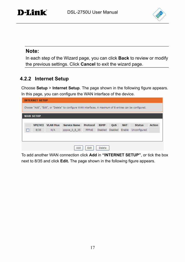
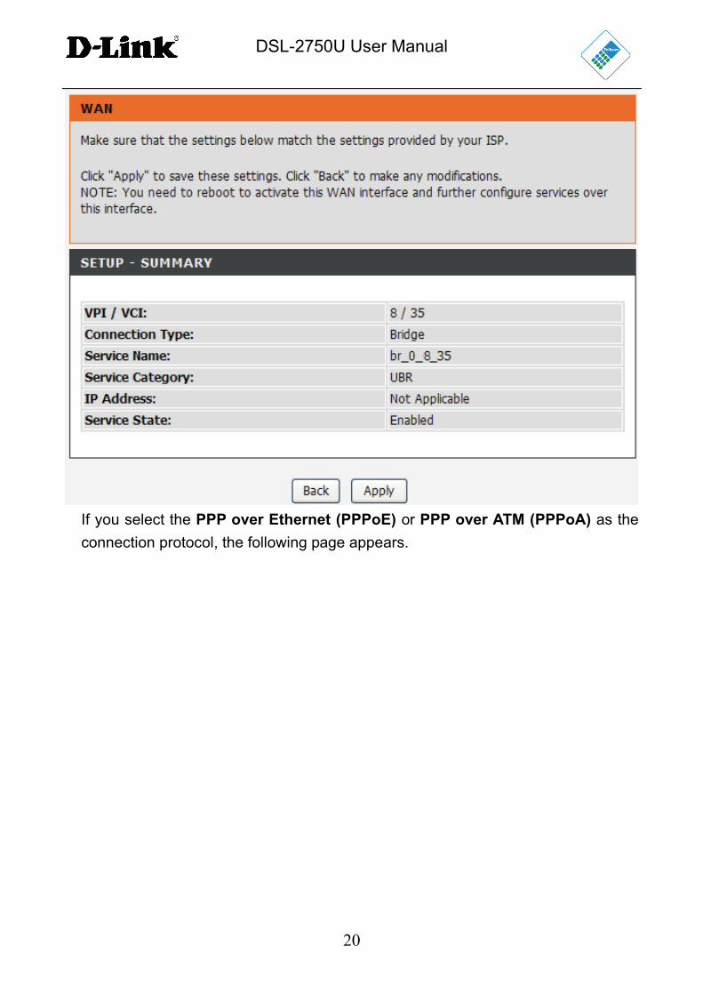
4.2.2 Internet Setup
Choose Setup > Internet Setup. The page shown in the following figure appears.
In this page, you can configure the WAN interface of the device.
To add another WAN connection click Add in “INTERNET SETUP”, or tick the box
next to 8/35 and click Edit. The page shown in the following figure appears.

DSL-2750U User Manual
18
DSL-2750U User Manual
19
PVC Settings: VPI is the virtual path between two points in an ATM network and
its valid value is from 0 to 255. Default value is 8.
VCI is the virtual channel between two points in an ATM network, ranging from 32
to 65535 (0 to 31 is reserved for local management of ATM traffic). Default is 35.
Service Category: Select one of the following values from the drop-down list -
UBR Without PCR, UBR With PCR, CBR, Non Realtime VBR or Realtime VBR.
Protocol: Select one of the following values from the drop-down list – Bridging,
PPP over ATM (PPPoA), PPP over Ethernet (PPPoE), MAC Encapsulation
Routing (MER), IP over ATM (IPoA).
Qos scheduler: You can select between either Strict Priority or Weighted Fair
Queuing. QoS Scheduler provides for two options of bandwidth management
that can monitor the importance of data packets and depending upon the priority
of the packet, give it higher or lower priority or bandwidth level.
Strict Priority Queuing (SPQ) - queues are assigned a priority order and served
strictly according to that order. A low-priority queue may be starved if there are
always packets in higher-priority queues.
Weighted fair queuing (WFQ) - queues are each assigned a weight, and they
share the bandwidth of the port according to that weight.
Based on network calculus the DSL-2750U can build analytical models for traffic
flows under SPQ and WFQ scheduling.
Encapsulation Mode: Select the method of encapsulation provided by your
ISP.Select an option from the drop-down list – LLC/SNAP-Bridging, VC/MUX.
Click Next, the page shown in the following figure appears.
DSL-2750U User Manual
20
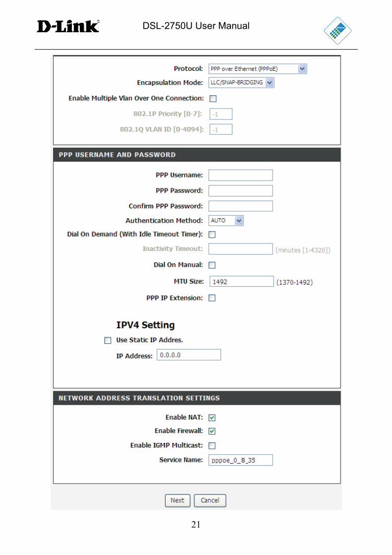
If you select the PPP over Ethernet (PPPoE) or PPP over ATM (PPPoA) as the
connection protocol, the following page appears.
DSL-2750U User Manual
21
DSL-2750U User Manual
22
PPP Username: The correct user name that your ISP provides you.
PPP Password: The correct password that your ISP provides you.
Authentication Method: The value can be AUTO, PAP, CHAP, or MSCHAP.
Usually, AUTO will be selected.
Dial on demand (with idle timeout timer): If this function is enabled, you
need to enter the idle timeout time. Within the preset time, if the modem does
not detect data flow , the modem automatically stops the PPPoE connection.
Once it detects data flow (like access to a webpage), the modem restarts the
PPPoE dialup.
If this function is disabled, the modem performs PPPoE dial-up all the time.
The PPPoE connnection does not stop, unless the modem is powered off or
the DSLAM or uplink equipment is faulty.
MTU Size: Maximum Transmission Unit.This function sometimes must be
modified to access the network successfully.
PPP IP extension: If this function is enabled, the WAN IP address obtained
by the modem through the built-in dial-up can be directly assigned to the PC
being attached to the modem (at this time, the modem connects to only one
PC). From the aspect of the PC user, the PC dials up to obtain an IP address.
But actually, the dial-up is done by the modem.
If this function is disabled, the modem itself obtains the WAN IP address.
Use Static IP Address: If this function is disabled, the modem obtains an IP
address assigned by uplink equipment such as BAS, through PPPoE dial-up.
If this function is enabled, the modem uses this IP address as the WAN IP
address.
Enable NAT: Select it to enable the NAT functions of the modem. If you do
not want to enable NAT and wish the modem user to access the Internet
normally, you must add a route on the uplink equipment. Otherwise, the
access to the Internet fails. Normally, NAT is enabled.
Enable Firewall: Enable or disable IP filtering.
Enable IGMP Multicast: IGMP proxy. For example, if you would like PPPoE
mode to support IPTV, enable this function.
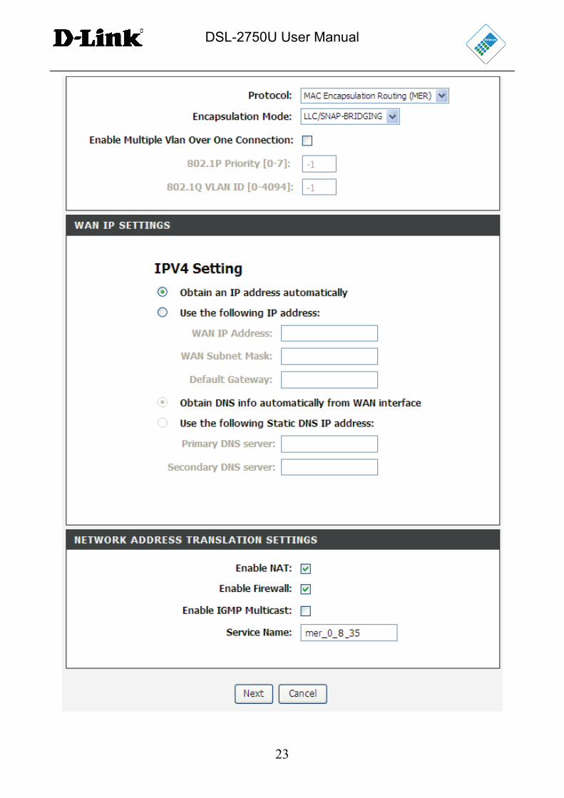
If you select the MAC Encapsulation Routing (MER) as the connection protocol,
the following page appears.
DSL-2750U User Manual
23
DSL-2750U User Manual
24
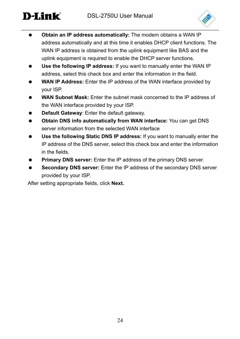
Obtain an IP address automatically: The modem obtains a WAN IP
address automatically and at this time it enables DHCP client functions. The
WAN IP address is obtained from the uplink equipment like BAS and the
uplink equipment is required to enable the DHCP server functions.
Use the following IP address: If you want to manually enter the WAN IP
address, select this check box and enter the information in the field.
WAN IP Address: Enter the IP address of the WAN interface provided by
your ISP.
WAN Subnet Mask: Enter the subnet mask concerned to the IP address of
the WAN interface provided by your ISP.
Default Gateway: Enter the default gateway.
Obtain DNS info automatically from WAN interface: You can get DNS
server information from the selected WAN interface
Use the following Static DNS IP address: If you want to manually enter the
IP address of the DNS server, select this check box and enter the information
in the fields.
Primary DNS server: Enter the IP address of the primary DNS server.
Secondary DNS server: Enter the IP address of the secondary DNS server
provided by your ISP.
After setting appropriate fields, click Next.
DSL-2750U User Manual
25
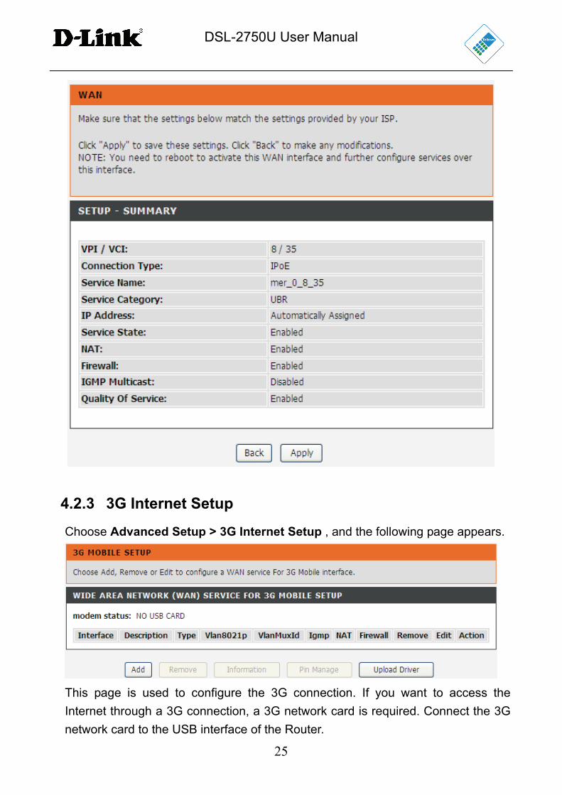
4.2.3 3G Internet Setup
Choose Advanced Setup > 3G Internet Setup , and the following page appears.
This page is used to configure the 3G connection. If you want to access the
Internet through a 3G connection, a 3G network card is required. Connect the 3G
network card to the USB interface of the Router.
DSL-2750U User Manual
26
If the 3G network card is installed, you may click the button on the Action column
to establish or disconnect the 3G connection.
Information: Click this button to display the information of the 3G network
card.
Upload Driver: For an un-supported USB dongle, click this button to upload
the new driver for USB support. The driver will be a text file which should be
obtained from your 3G dongle provider.
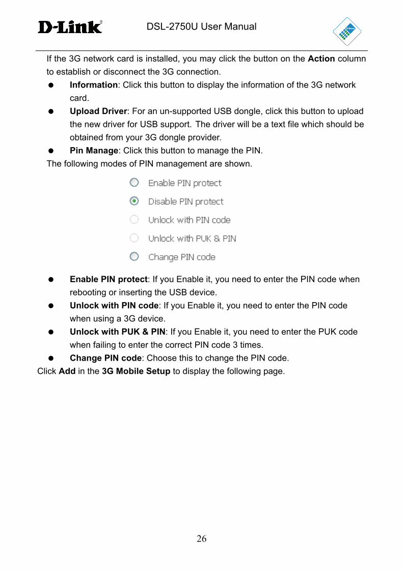
Pin Manage: Click this button to manage the PIN.
The following modes of PIN management are shown.
Enable PIN protect: If you Enable it, you need to enter the PIN code when
rebooting or inserting the USB device.
Unlock with PIN code: If you Enable it, you need to enter the PIN code
when using a 3G device.
Unlock with PUK & PIN: If you Enable it, you need to enter the PUK code
when failing to enter the correct PIN code 3 times.
Change PIN code: Choose this to change the PIN code.
Click Add in the 3G Mobile Setup to display the following page.
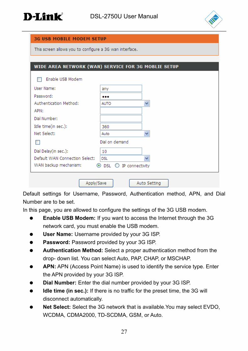
DSL-2750U User Manual
27
Default settings for Username, Password, Authentication method, APN, and Dial
Number are to be set.
In this page, you are allowed to configure the settings of the 3G USB modem.
Enable USB Modem: If you want to access the Internet through the 3G
network card, you must enable the USB modem.
User Name: Username provided by your 3G ISP.
Password: Password provided by your 3G ISP.
Authentication Method: Select a proper authentication method from the
drop- down list. You can select Auto, PAP, CHAP, or MSCHAP.
APN: APN (Access Point Name) is used to identify the service type. Enter
the APN provided by your 3G ISP.
Dial Number: Enter the dial number provided by your 3G ISP.
Idle time (in sec.): If there is no traffic for the preset time, the 3G will
disconnect automatically.
Net Select: Select the 3G network that is available.You may select EVDO,
WCDMA, CDMA2000, TD-SCDMA, GSM, or Auto.
DSL-2750U User Manual
28
Dial on demand: Within the preset time, if the modem does not detect data
flow , the modem automatically stops the 3G connection. Once it detects
data flow (e.g. access to a webpage), the modem restarts the 3G dialup.
Dial Delay (in sec.): The 3G delays dial after the DSL is disconnected.
Default WAN Connection Select: You can select DSL or 3G from the
drop-down list.
WAN backup mechanism: The 3G connection is used as backup for the
DSL connection.
– DSL: If the DSL is disconnected, the 3G starts to dial.
– IP connectivity: If the system fails to ping the specified IP
address, the 3G starts to dial.
After adding the settings, click the Apply/Save button to save the settings.
You may also click the auto setting button to automatically configure the 3G
connection.
After clicking the Apply/Save button, the settings will take effect.
Note:
When there is no DSL WAN connection, insert the 3G network card, and the
system will perform a dial-up automatically. If the DSL WAN connection and the
3G connection coexist, the DSL WAN connection takes priority over the 3G
connection. When the DSL WAN connection starts to perform a dial-up, the 3G
connection will be disconnected. If the DSL WAN connection has been
established, you may manually perform a 3G dial-up, and then the DSL WAN
connection will be disconnected.
4.2.4 Wireless Connection
This section includes the wireless connection setup wizard and WPS setup wizard.
There are two ways to setup your wireless connection. You can use the Wireless
Connection Setup Wizard or you can manually configure the connection.
Choose Setup > Wireless Connection. The Wireless Connection page shown in
the following figure appears.
DSL-2750U User Manual
29
Figure 3
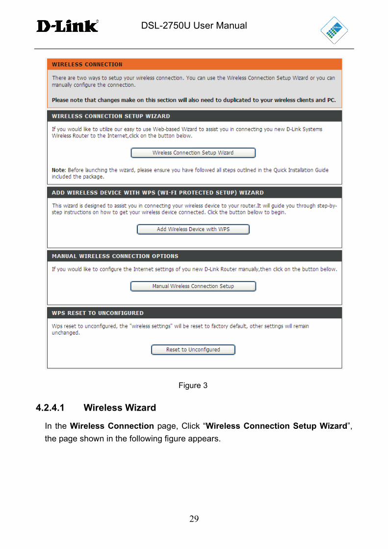
4.2.4.1 Wireless Wizard
In the Wireless Connection page, Click “Wireless Connection Setup Wizard”,
the page shown in the following figure appears.
DSL-2750U User Manual
30
If you select “Use WPA encryption instead of WEP” and “Manually assign a
network key”, then click “Next”, the page shown in the following figure appears.
If you only select “Manually assign a network key”, then click “Next”, the page
shown in the following figure appears.
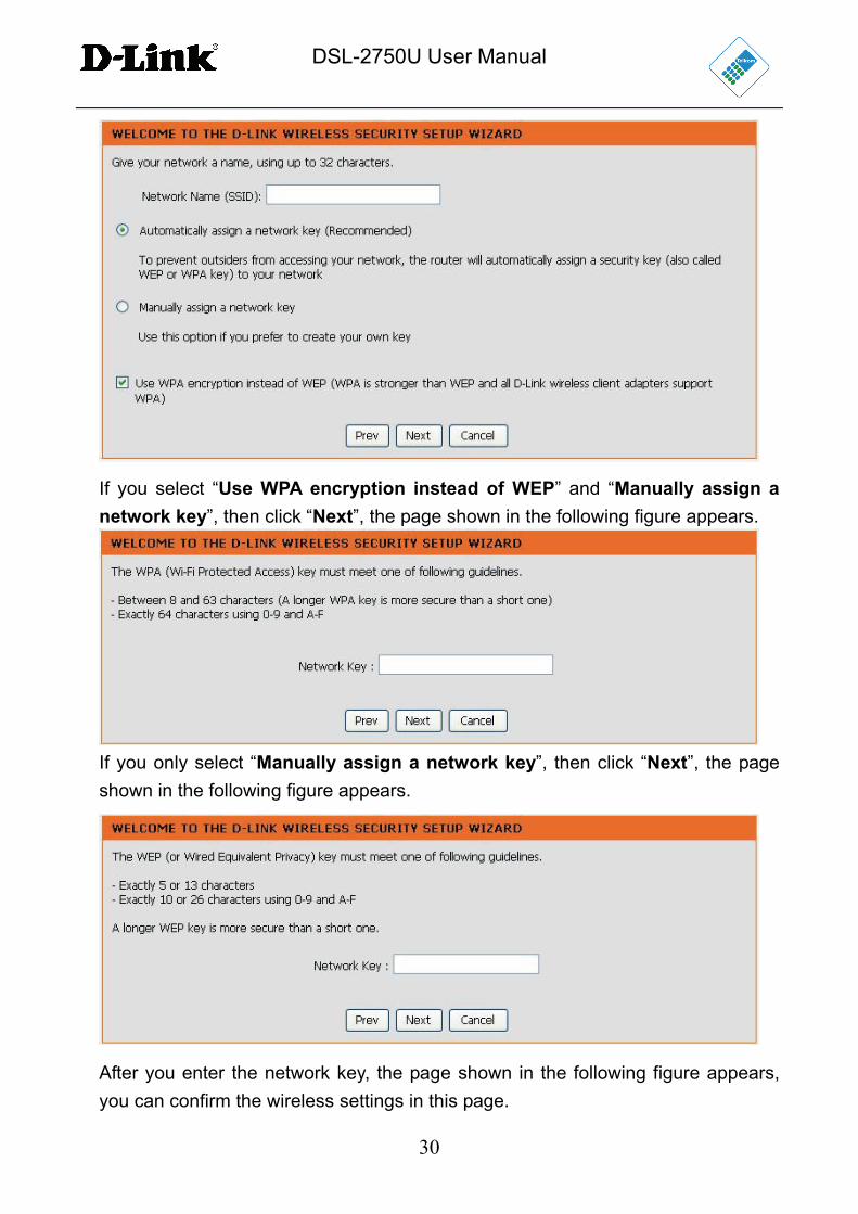
After you enter the network key, the page shown in the following figure appears,
you can confirm the wireless settings in this page.
DSL-2750U User Manual
31
Click Save to save the settings.
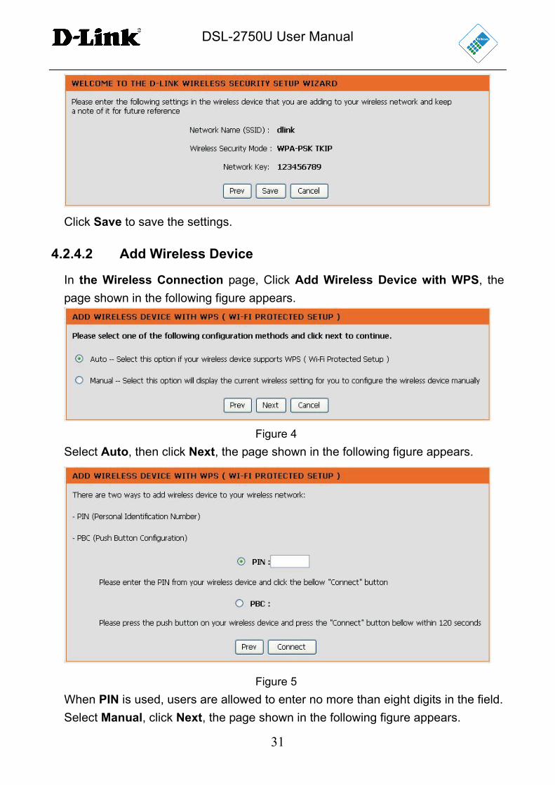
4.2.4.2 Add Wireless Device
In the Wireless Connection page, Click Add Wireless Device with WPS, the
page shown in the following figure appears.
Figure 4
Select Auto, then click Next, the page shown in the following figure appears.
Figure 5
When PIN is used, users are allowed to enter no more than eight digits in the field.
Select Manual, click Next, the page shown in the following figure appears.
DSL-2750U User Manual
32
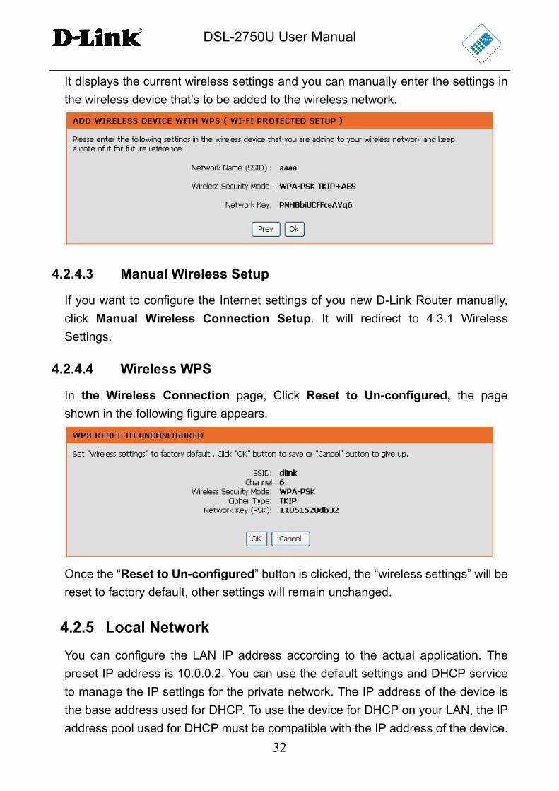
It displays the current wireless settings and you can manually enter the settings in
the wireless device that’s to be added to the wireless network.
4.2.4.3 Manual Wireless Setup
If you want to configure the Internet settings of you new D-Link Router manually,
click Manual Wireless Connection Setup. It will redirect to 4.3.1 Wireless
Settings.
4.2.4.4 Wireless WPS
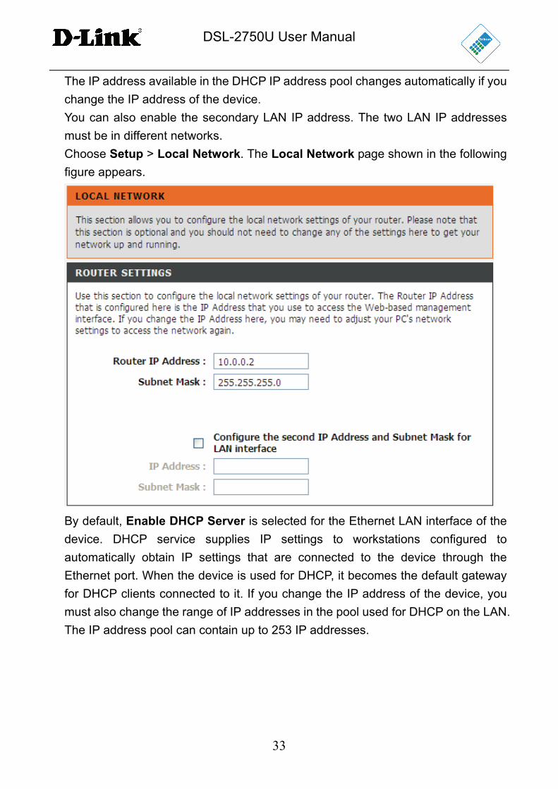
In the Wireless Connection page, Click Reset to Un-configured, the page
shown in the following figure appears.
Once the “Reset to Un-configured” button is clicked, the “wireless settings” will be
reset to factory default, other settings will remain unchanged.
4.2.5 Local Network
You can configure the LAN IP address according to the actual application. The
preset IP address is 10.0.0.2. You can use the default settings and DHCP service
to manage the IP settings for the private network. The IP address of the device is
the base address used for DHCP. To use the device for DHCP on your LAN, the IP
address pool used for DHCP must be compatible with the IP address of the device.
DSL-2750U User Manual
33
The IP address available in the DHCP IP address pool changes automatically if you
change the IP address of the device.
You can also enable the secondary LAN IP address. The two LAN IP addresses
must be in different networks.
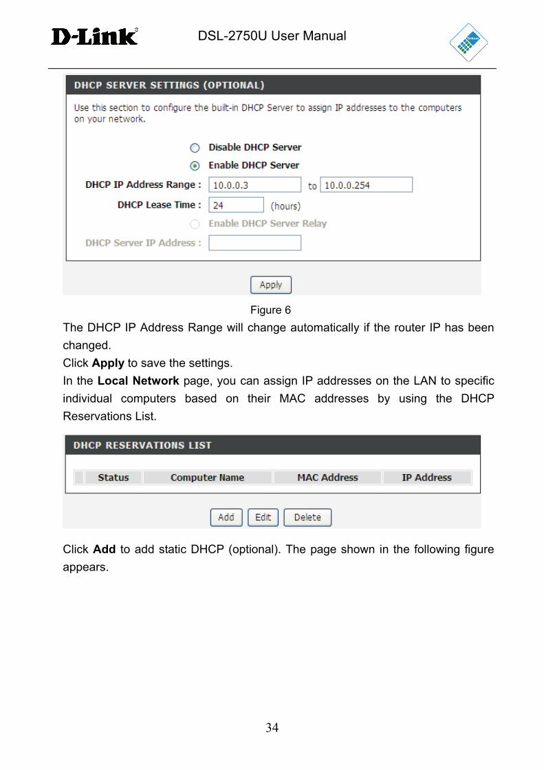
Choose Setup > Local Network. The Local Network page shown in the following
figure appears.
By default, Enable DHCP Server is selected for the Ethernet LAN interface of the
device. DHCP service supplies IP settings to workstations configured to
automatically obtain IP settings that are connected to the device through the
Ethernet port. When the device is used for DHCP, it becomes the default gateway
for DHCP clients connected to it. If you change the IP address of the device, you
must also change the range of IP addresses in the pool used for DHCP on the LAN.
The IP address pool can contain up to 253 IP addresses.
DSL-2750U User Manual
34
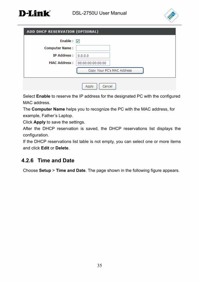
Figure 6
The DHCP IP Address Range will change automatically if the router IP has been
changed.
Click Apply to save the settings.
In the Local Network page, you can assign IP addresses on the LAN to specific
individual computers based on their MAC addresses by using the DHCP
Reservations List.
Click Add to add static DHCP (optional). The page shown in the following figure
appears.
DSL-2750U User Manual
35
Select Enable to reserve the IP address for the designated PC with the configured
MAC address.
The Computer Name helps you to recognize the PC with the MAC address, for
example, Father’s Laptop.
Click Apply to save the settings.
After the DHCP reservation is saved, the DHCP reservations list displays the
configuration.
If the DHCP reservations list table is not empty, you can select one or more items
and click Edit or Delete.
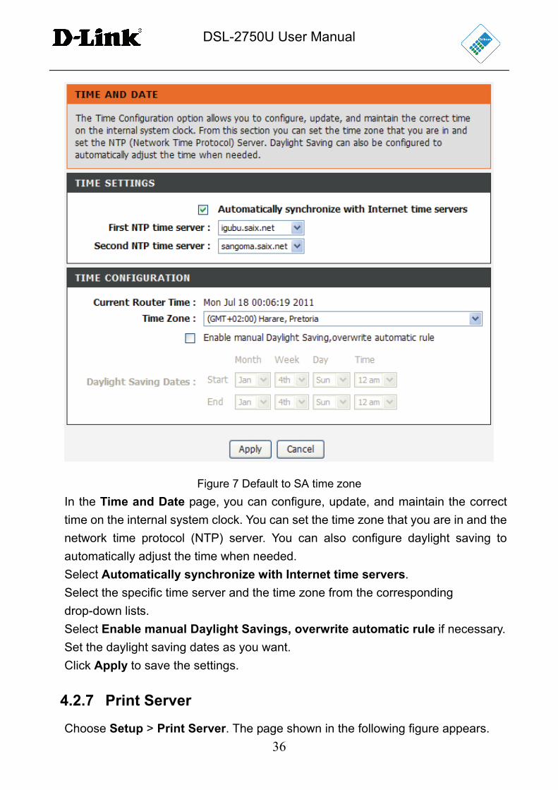
4.2.6 Time and Date
Choose Setup > Time and Date. The page shown in the following figure appears.
DSL-2750U User Manual
36
Figure 7 Default to SA time zone
In the Time and Date page, you can configure, update, and maintain the correct
time on the internal system clock. You can set the time zone that you are in and the
network time protocol (NTP) server. You can also configure daylight saving to
automatically adjust the time when needed.
Select Automatically synchronize with Internet time servers.
Select the specific time server and the time zone from the corresponding
drop-down lists.
Select Enable manual Daylight Savings, overwrite automatic rule if necessary.
Set the daylight saving dates as you want.
Click Apply to save the settings.
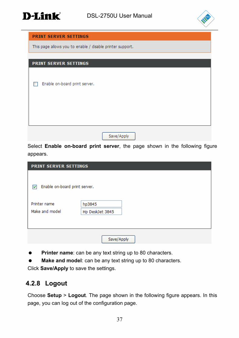
4.2.7 Print Server
Choose Setup > Print Server. The page shown in the following figure appears.
DSL-2750U User Manual
37
Select Enable on-board print server, the page shown in the following figure
appears.
Printer name: can be any text string up to 80 characters.
Make and model: can be any text string up to 80 characters.
Click Save/Apply to save the settings.
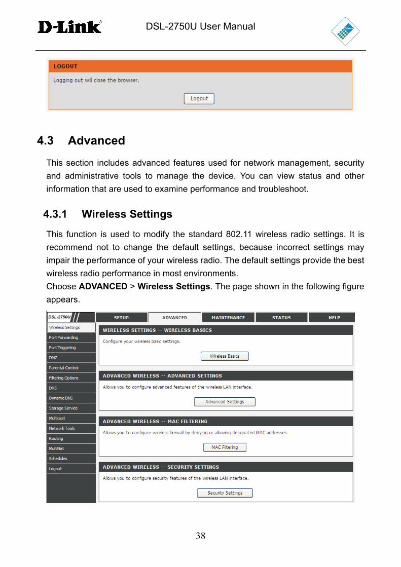
4.2.8 Logout
Choose Setup > Logout. The page shown in the following figure appears. In this
page, you can log out of the configuration page.
DSL-2750U User Manual
38
4.3 Advanced
This section includes advanced features used for network management, security
and administrative tools to manage the device. You can view status and other
information that are used to examine performance and troubleshoot.
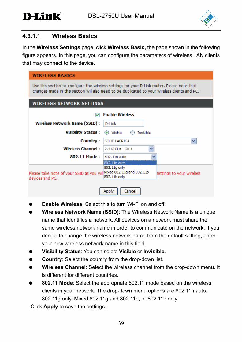
4.3.1 Wireless Settings
This function is used to modify the standard 802.11 wireless radio settings. It is
recommend not to change the default settings, because incorrect settings may
impair the performance of your wireless radio. The default settings provide the best
wireless radio performance in most environments.
Choose ADVANCED > Wireless Settings. The page shown in the following figure
appears.
DSL-2750U User Manual
39
4.3.1.1 Wireless Basics
In the Wireless Settings page, click Wireless Basic, the page shown in the following
figure appears. In this page, you can configure the parameters of wireless LAN clients
that may connect to the device.
Enable Wireless: Select this to turn Wi-Fi on and off.
Wireless Network Name (SSID): The Wireless Network Name is a unique
name that identifies a network. All devices on a network must share the
same wireless network name in order to communicate on the network. If you
decide to change the wireless network name from the default setting, enter
your new wireless network name in this field.
Visibility Status: You can select Visible or Invisible.
Country: Select the country from the drop-down list.
Wireless Channel: Select the wireless channel from the drop-down menu. It
is different for different countries.
802.11 Mode: Select the appropriate 802.11 mode based on the wireless
clients in your network. The drop-down menu options are 802.11n auto,
802.11g only, Mixed 802.11g and 802.11b, or 802.11b only.
Click Apply to save the settings.
DSL-2750U User Manual
40
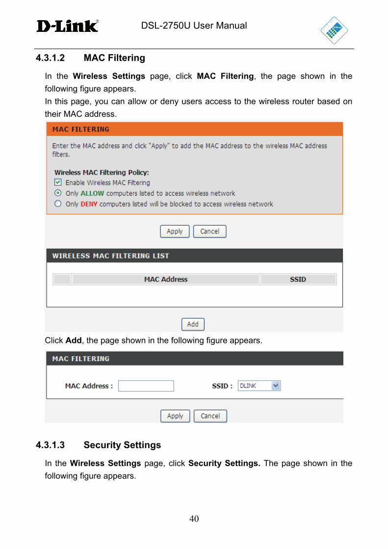
4.3.1.2 MAC Filtering
In the Wireless Settings page, click MAC Filtering, the page shown in the
following figure appears.
In this page, you can allow or deny users access to the wireless router based on
their MAC address.
Click Add, the page shown in the following figure appears.
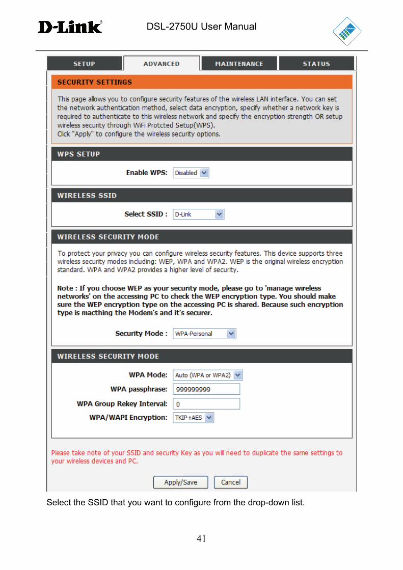
4.3.1.3 Security Settings
In the Wireless Settings page, click Security Settings. The page shown in the
following figure appears.
DSL-2750U User Manual
41
Select the SSID that you want to configure from the drop-down list.
DSL-2750U User Manual
42
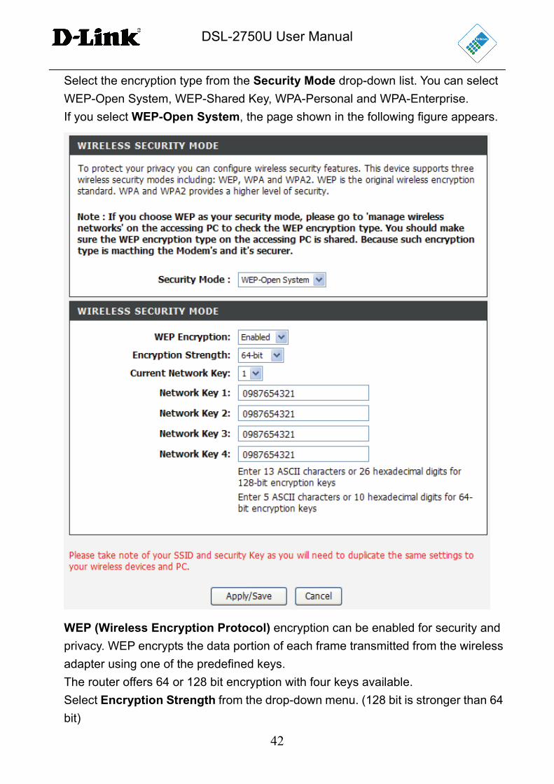
Select the encryption type from the Security Mode drop-down list. You can select
WEP-Open System, WEP-Shared Key, WPA-Personal and WPA-Enterprise.
If you select WEP-Open System, the page shown in the following figure appears.
WEP (Wireless Encryption Protocol) encryption can be enabled for security and
privacy. WEP encrypts the data portion of each frame transmitted from the wireless
adapter using one of the predefined keys.
The router offers 64 or 128 bit encryption with four keys available.
Select Encryption Strength from the drop-down menu. (128 bit is stronger than 64
bit)
DSL-2750U User Manual
43
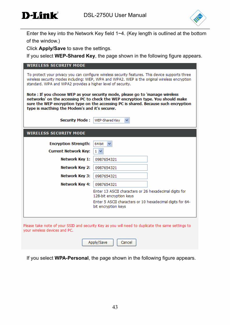
Enter the key into the Network Key field 1~4. (Key length is outlined at the bottom
of the window.)
Click Apply/Save to save the settings.
If you select WEP-Shared Key, the page shown in the following figure appears.
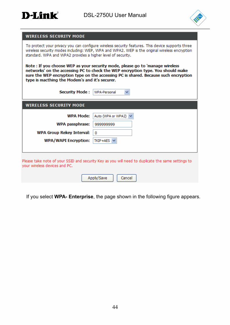
If you select WPA-Personal, the page shown in the following figure appears.
DSL-2750U User Manual
44
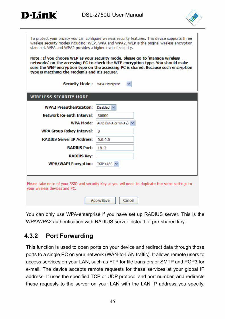
If you select WPA- Enterprise, the page shown in the following figure appears.
DSL-2750U User Manual
45
You can only use WPA-enterprise if you have set up RADIUS server. This is the
WPA/WPA2 authentication with RADIUS server instead of pre-shared key.
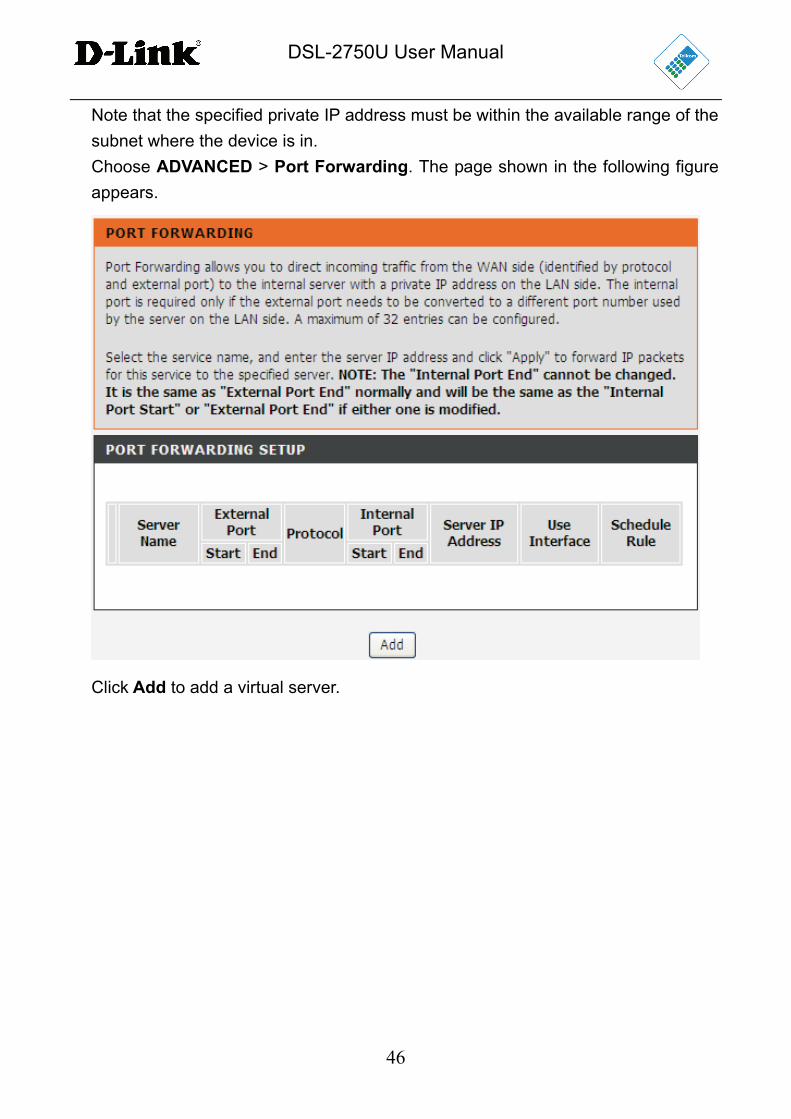
4.3.2 Port Forwarding
This function is used to open ports on your device and redirect data through those
ports to a single PC on your network (WAN-to-LAN traffic). It allows remote users to
access services on your LAN, such as FTP for file transfers or SMTP and POP3 for
e-mail. The device accepts remote requests for these services at your global IP
address. It uses the specified TCP or UDP protocol and port number, and redirects
these requests to the server on your LAN with the LAN IP address you specify.
DSL-2750U User Manual
46
Note that the specified private IP address must be within the available range of the
subnet where the device is in.
Choose ADVANCED > Port Forwarding. The page shown in the following figure
appears.
Click Add to add a virtual server.
DSL-2750U User Manual
47
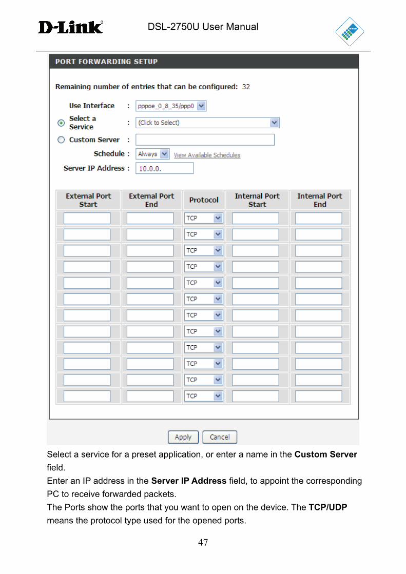
Select a service for a preset application, or enter a name in the Custom Server
field.
Enter an IP address in the Server IP Address field, to appoint the corresponding
PC to receive forwarded packets.
The Ports show the ports that you want to open on the device. The TCP/UDP
means the protocol type used for the opened ports.
DSL-2750U User Manual
48
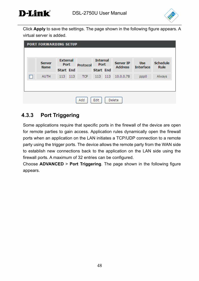
Click Apply to save the settings. The page shown in the following figure appears. A
virtual server is added.
4.3.3 Port Triggering
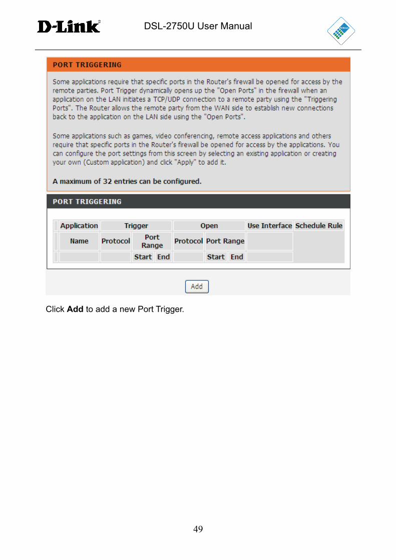
Some applications require that specific ports in the firewall of the device are open
for remote parties to gain access. Application rules dynamically open the firewall
ports when an application on the LAN initiates a TCP/UDP connection to a remote
party using the trigger ports. The device allows the remote party from the WAN side
to establish new connections back to the application on the LAN side using the
firewall ports. A maximum of 32 entries can be configured.
Choose ADVANCED > Port Triggering. The page shown in the following figure
appears.
DSL-2750U User Manual
49
Click Add to add a new Port Trigger.
DSL-2750U User Manual
50
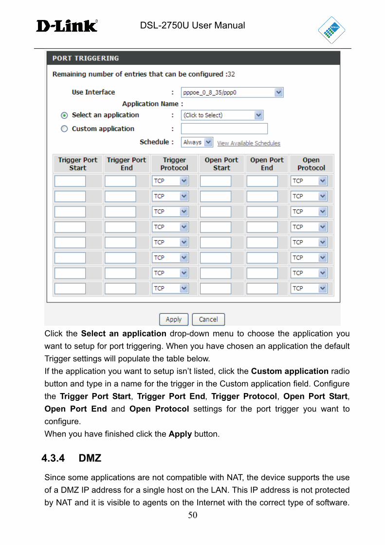
Click the Select an application drop-down menu to choose the application you
want to setup for port triggering. When you have chosen an application the default
Trigger settings will populate the table below.
If the application you want to setup isn’t listed, click the Custom application radio
button and type in a name for the trigger in the Custom application field. Configure
the Trigger Port Start, Trigger Port End, Trigger Protocol, Open Port Start,
Open Port End and Open Protocol settings for the port trigger you want to
configure.
When you have finished click the Apply button.
4.3.4 DMZ
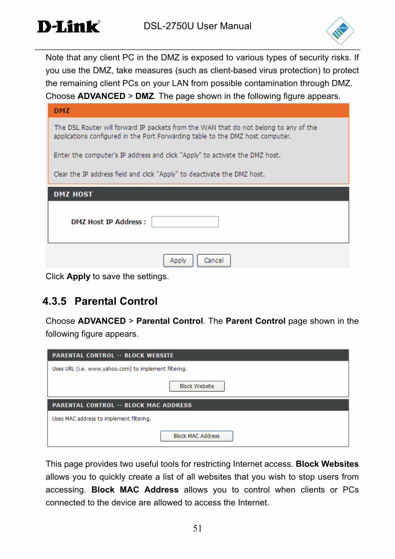
Since some applications are not compatible with NAT, the device supports the use
of a DMZ IP address for a single host on the LAN. This IP address is not protected
by NAT and it is visible to agents on the Internet with the correct type of software.
DSL-2750U User Manual
51
Note that any client PC in the DMZ is exposed to various types of security risks. If
you use the DMZ, take measures (such as client-based virus protection) to protect
the remaining client PCs on your LAN from possible contamination through DMZ.
Choose ADVANCED > DMZ. The page shown in the following figure appears.
Click Apply to save the settings.
4.3.5 Parental Control
Choose ADVANCED > Parental Control. The Parent Control page shown in the
following figure appears.
This page provides two useful tools for restricting Internet access. Block Websites
allows you to quickly create a list of all websites that you wish to stop users from
accessing. Block MAC Address allows you to control when clients or PCs
connected to the device are allowed to access the Internet.
DSL-2750U User Manual
52
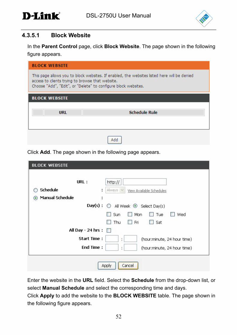
4.3.5.1 Block Website
In the Parent Control page, click Block Website. The page shown in the following
figure appears.
Click Add. The page shown in the following page appears.
Enter the website in the URL field. Select the Schedule from the drop-down list, or
select Manual Schedule and select the corresponding time and days.
Click Apply to add the website to the BLOCK WEBSITE table. The page shown in
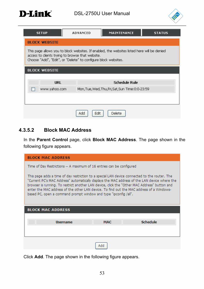
the following figure appears.
DSL-2750U User Manual
53
4.3.5.2 Block MAC Address
In the Parent Control page, click Block MAC Address. The page shown in the
following figure appears.
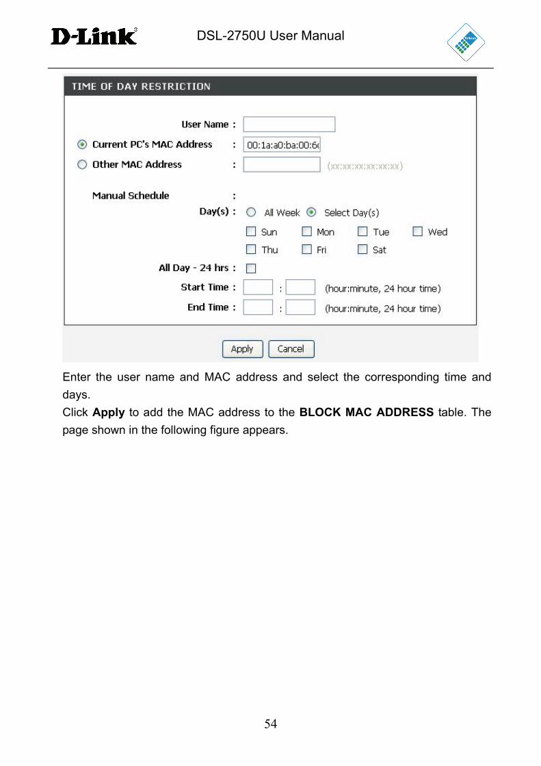
Click Add. The page shown in the following figure appears.
DSL-2750U User Manual
54
Enter the user name and MAC address and select the corresponding time and
days.
Click Apply to add the MAC address to the BLOCK MAC ADDRESS table. The
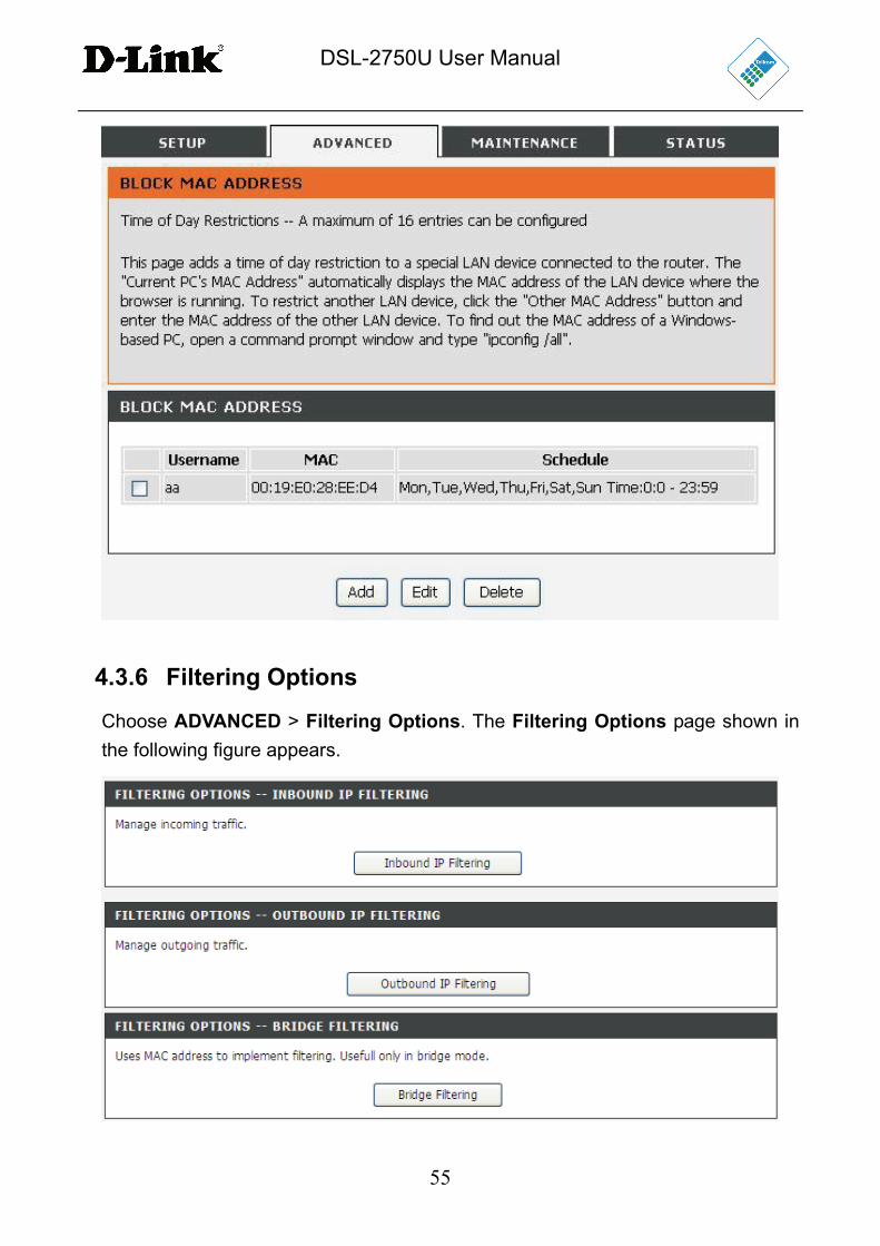
page shown in the following figure appears.
DSL-2750U User Manual
55
4.3.6 Filtering Options
Choose ADVANCED > Filtering Options. The Filtering Options page shown in
the following figure appears.
DSL-2750U User Manual
56
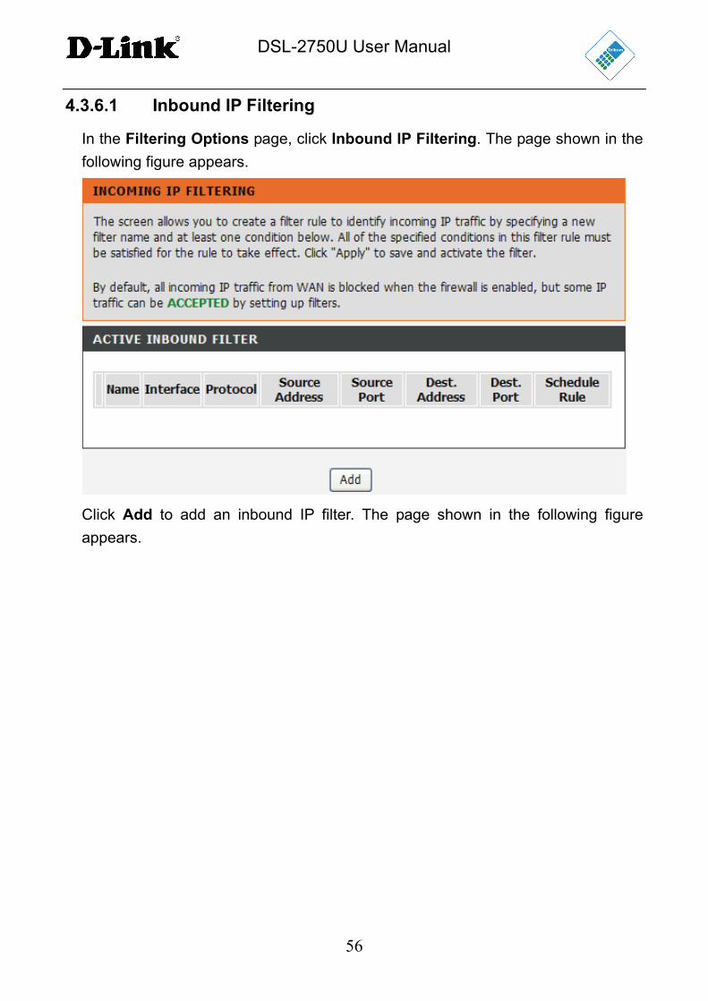
4.3.6.1 Inbound IP Filtering
In the Filtering Options page, click Inbound IP Filtering. The page shown in the
following figure appears.
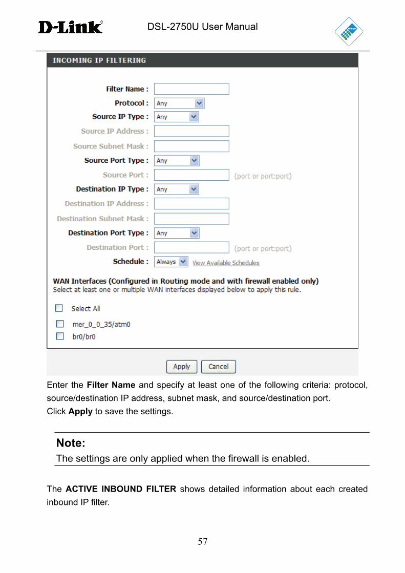
Click Add to add an inbound IP filter. The page shown in the following figure
appears.
DSL-2750U User Manual
57
Enter the Filter Name and specify at least one of the following criteria: protocol,
source/destination IP address, subnet mask, and source/destination port.
Click Apply to save the settings.
Note: The settings are only applied when the firewall is enabled.
The ACTIVE INBOUND FILTER shows detailed information about each created
inbound IP filter.
DSL-2750U User Manual
58
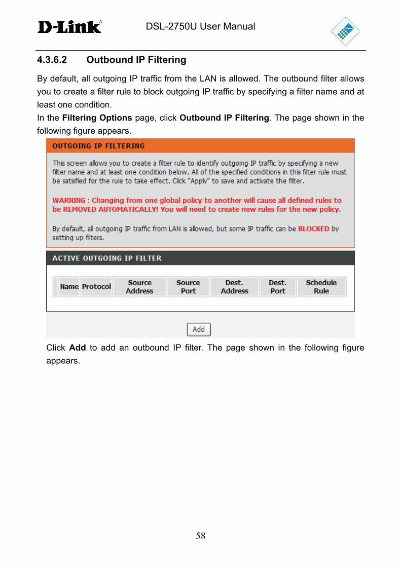
4.3.6.2 Outbound IP Filtering
By default, all outgoing IP traffic from the LAN is allowed. The outbound filter allows
you to create a filter rule to block outgoing IP traffic by specifying a filter name and at
least one condition.
In the Filtering Options page, click Outbound IP Filtering. The page shown in the
following figure appears.
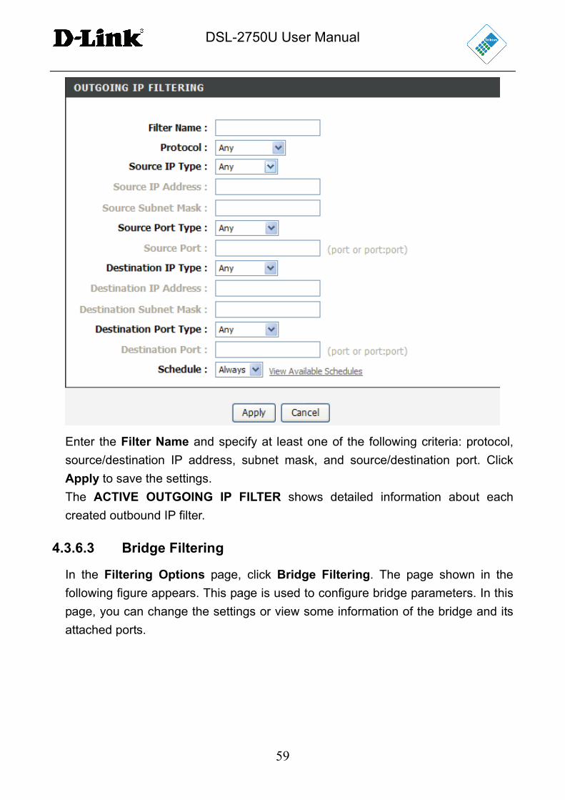
Click Add to add an outbound IP filter. The page shown in the following figure
appears.
DSL-2750U User Manual
59
Enter the Filter Name and specify at least one of the following criteria: protocol,
source/destination IP address, subnet mask, and source/destination port. Click
Apply to save the settings.
The ACTIVE OUTGOING IP FILTER shows detailed information about each
created outbound IP filter.
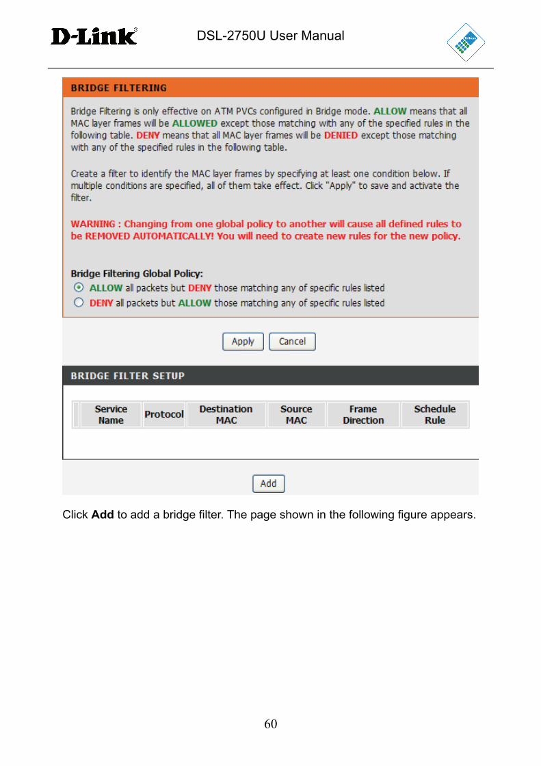
4.3.6.3 Bridge Filtering
In the Filtering Options page, click Bridge Filtering. The page shown in the
following figure appears. This page is used to configure bridge parameters. In this
page, you can change the settings or view some information of the bridge and its
attached ports.
DSL-2750U User Manual
60
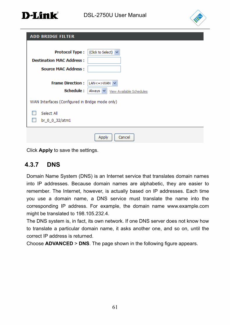
Click Add to add a bridge filter. The page shown in the following figure appears.
DSL-2750U User Manual
61
Click Apply to save the settings.
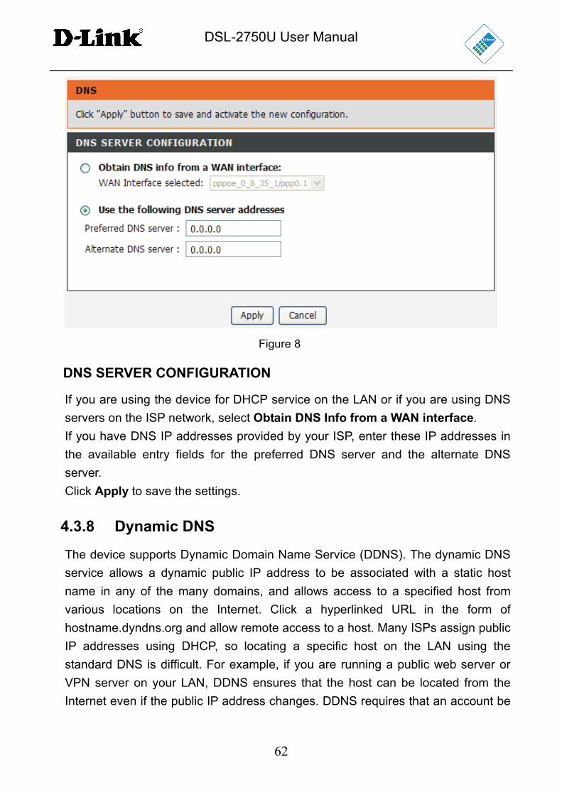
4.3.7 DNS
Domain Name System (DNS) is an Internet service that translates domain names
into IP addresses. Because domain names are alphabetic, they are easier to
remember. The Internet, however, is actually based on IP addresses. Each time
you use a domain name, a DNS service must translate the name into the
corresponding IP address. For example, the domain name www.example.com
might be translated to 198.105.232.4.
The DNS system is, in fact, its own network. If one DNS server does not know how
to translate a particular domain name, it asks another one, and so on, until the
correct IP address is returned.
Choose ADVANCED > DNS. The page shown in the following figure appears.
DSL-2750U User Manual
62
Figure 8
DNS SERVER CONFIGURATION
If you are using the device for DHCP service on the LAN or if you are using DNS
servers on the ISP network, select Obtain DNS Info from a WAN interface.
If you have DNS IP addresses provided by your ISP, enter these IP addresses in
the available entry fields for the preferred DNS server and the alternate DNS
server.
Click Apply to save the settings.
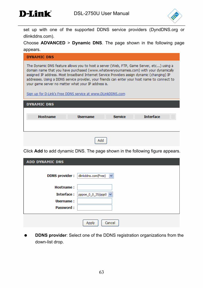
4.3.8 Dynamic DNS
The device supports Dynamic Domain Name Service (DDNS). The dynamic DNS
service allows a dynamic public IP address to be associated with a static host
name in any of the many domains, and allows access to a specified host from
various locations on the Internet. Click a hyperlinked URL in the form of
hostname.dyndns.org and allow remote access to a host. Many ISPs assign public
IP addresses using DHCP, so locating a specific host on the LAN using the
standard DNS is difficult. For example, if you are running a public web server or
VPN server on your LAN, DDNS ensures that the host can be located from the
Internet even if the public IP address changes. DDNS requires that an account be
DSL-2750U User Manual
63
set up with one of the supported DDNS service providers (DyndDNS.org or
dlinkddns.com).
Choose ADVANCED > Dynamic DNS. The page shown in the following page
appears.
Click Add to add dynamic DNS. The page shown in the following figure appears.
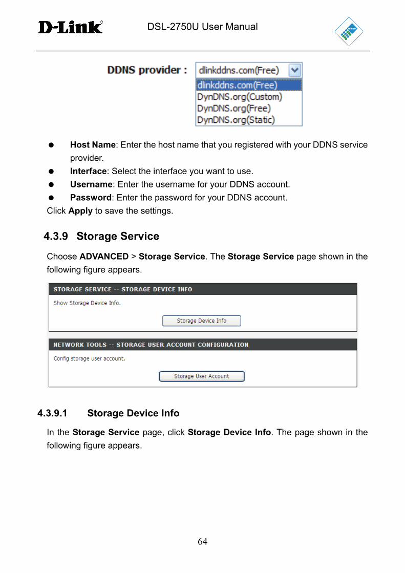
DDNS provider: Select one of the DDNS registration organizations from the
down-list drop.
DSL-2750U User Manual
64
Host Name: Enter the host name that you registered with your DDNS service
provider.
Interface: Select the interface you want to use.
Username: Enter the username for your DDNS account.
Password: Enter the password for your DDNS account.
Click Apply to save the settings.
4.3.9 Storage Service
Choose ADVANCED > Storage Service. The Storage Service page shown in the
following figure appears.
4.3.9.1 Storage Device Info
In the Storage Service page, click Storage Device Info. The page shown in the
following figure appears.

DSL-2750U User Manual
65
Figure 9
When you insert a USB storage device, this page will show the information of the
USB storage device, such as file system, total space, and used space.
4.3.9.2 User Accounts
In the Storage Service page, click Storage User Account. The page shown in the
following figure appears.
Click Add to add a user. The page shown in the following figure appears.
Username: Set a valid username that will access the CPE’s samba server
DSL-2750U User Manual
66
Password: Specify the user’s password
Confirm Password: Re-enter the user’s password
volumeName: The name of the directory you want to share
4.3.10 Multicast
Choose ADVANCED > Multicast. The page shown in the following figure appears.
Figure 10
Default Version: IGMP version
Query Interval(s):The query interval is the amount of time in seconds
between IGMP General Query messages sent by the router (if the router is
querying on this subnet)
Query Response Interval (1/10s): The query response interval is the
maximum amount of time in seconds that the IGMP router waits to receive a
response to a General Query message. The query response interval is the
Maximum Response Time field in the IGMP v2 Host Membership Query
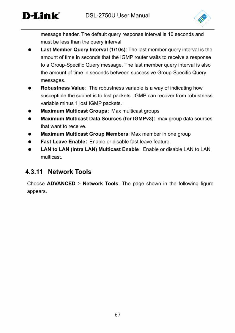
DSL-2750U User Manual
67
message header. The default query response interval is 10 seconds and
must be less than the query interval
Last Member Query Interval (1/10s): The last member query interval is the
amount of time in seconds that the IGMP router waits to receive a response
to a Group-Specific Query message. The last member query interval is also
the amount of time in seconds between successive Group-Specific Query
messages.
Robustness Value: The robustness variable is a way of indicating how
susceptible the subnet is to lost packets. IGMP can recover from robustness
variable minus 1 lost IGMP packets.
Maximum Multicast Groups: Max multicast groups Maximum Multicast Data Sources (for IGMPv3): max group data sources
that want to receive. Maximum Multicast Group Members: Max member in one group
Fast Leave Enable: Enable or disable fast leave feature. LAN to LAN (Intra LAN) Multicast Enable: Enable or disable LAN to LAN
multicast.
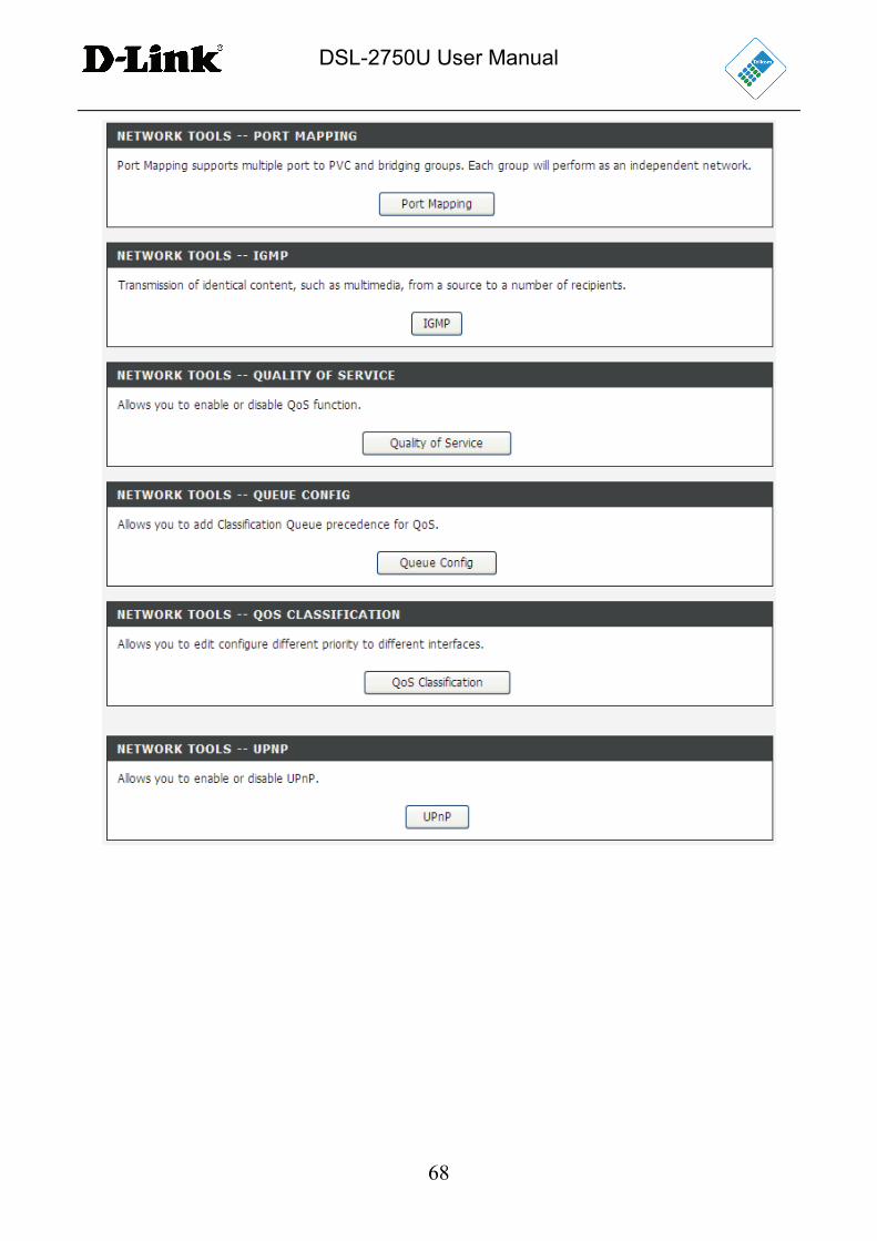
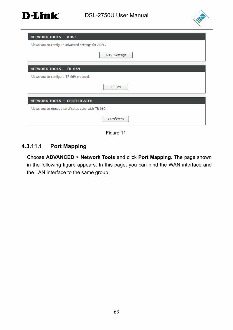
4.3.11 Network Tools
Choose ADVANCED > Network Tools. The page shown in the following figure
appears.
DSL-2750U User Manual
68
DSL-2750U User Manual
69
Figure 11
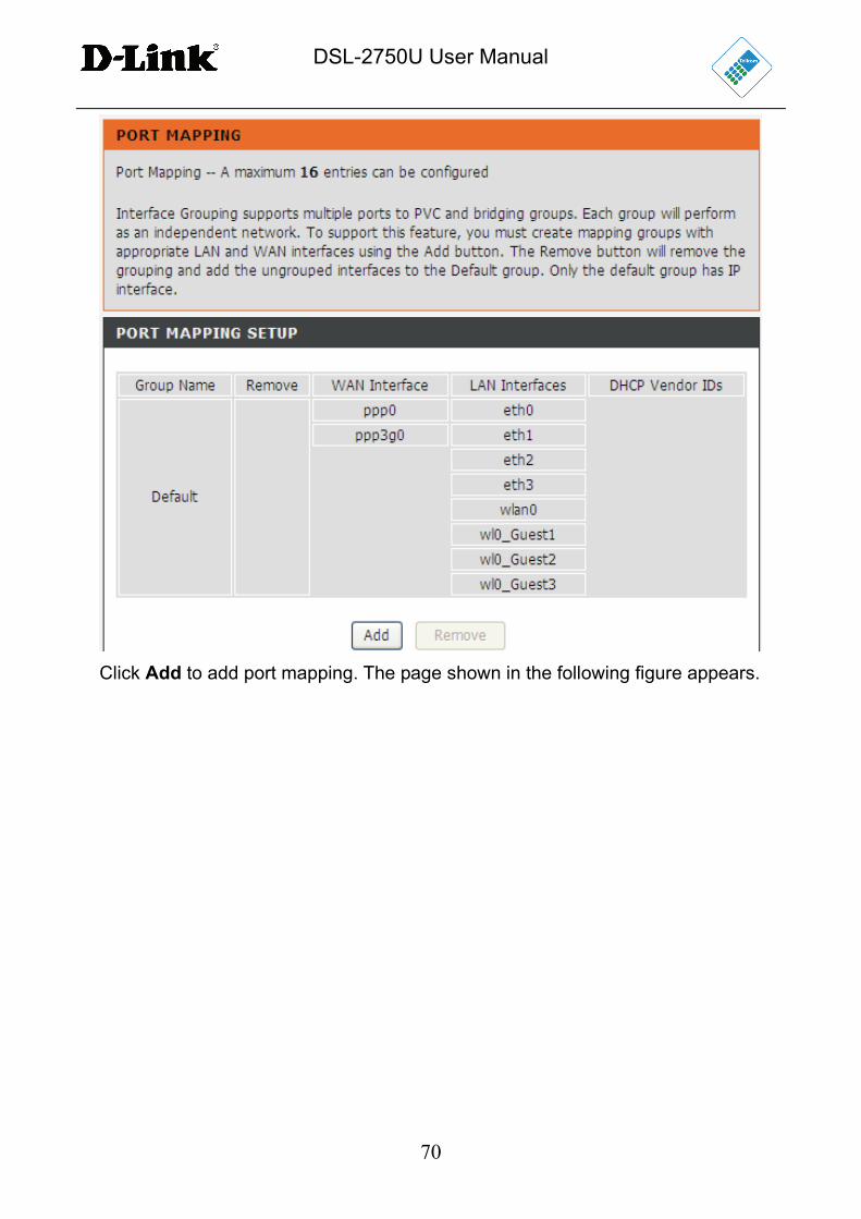
4.3.11.1 Port Mapping
Choose ADVANCED > Network Tools and click Port Mapping. The page shown
in the following figure appears. In this page, you can bind the WAN interface and
the LAN interface to the same group.
DSL-2750U User Manual
70
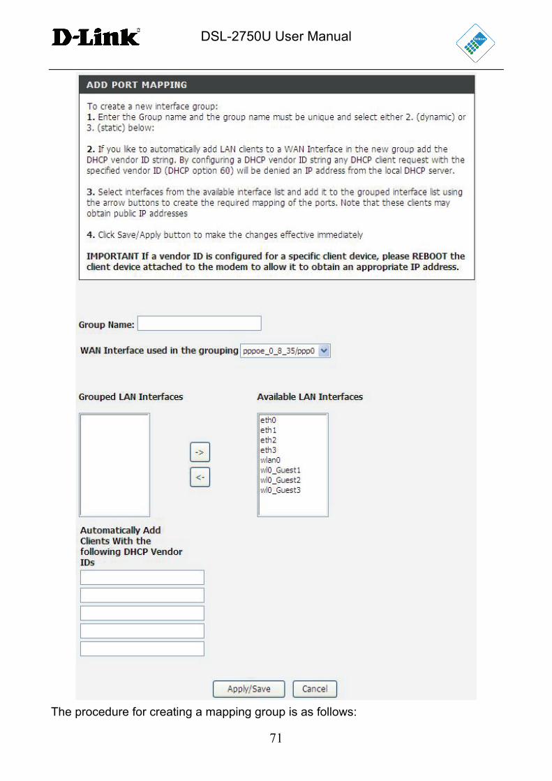
Click Add to add port mapping. The page shown in the following figure appears.
DSL-2750U User Manual
71
The procedure for creating a mapping group is as follows:
DSL-2750U User Manual
72
Step 1 Enter the group name.
Step 2 Select the WAN interface for your new group.
Step 3 Select the LAN interfaces from the Available Interface list and click the
<- arrow button to add them to the grouped interface list, in order to
create the required mapping of the ports. The group name must be
unique.
Step 4 Enter the optional information of DHCP vendor IDs.
Step 5 Click Apply to save the settings.
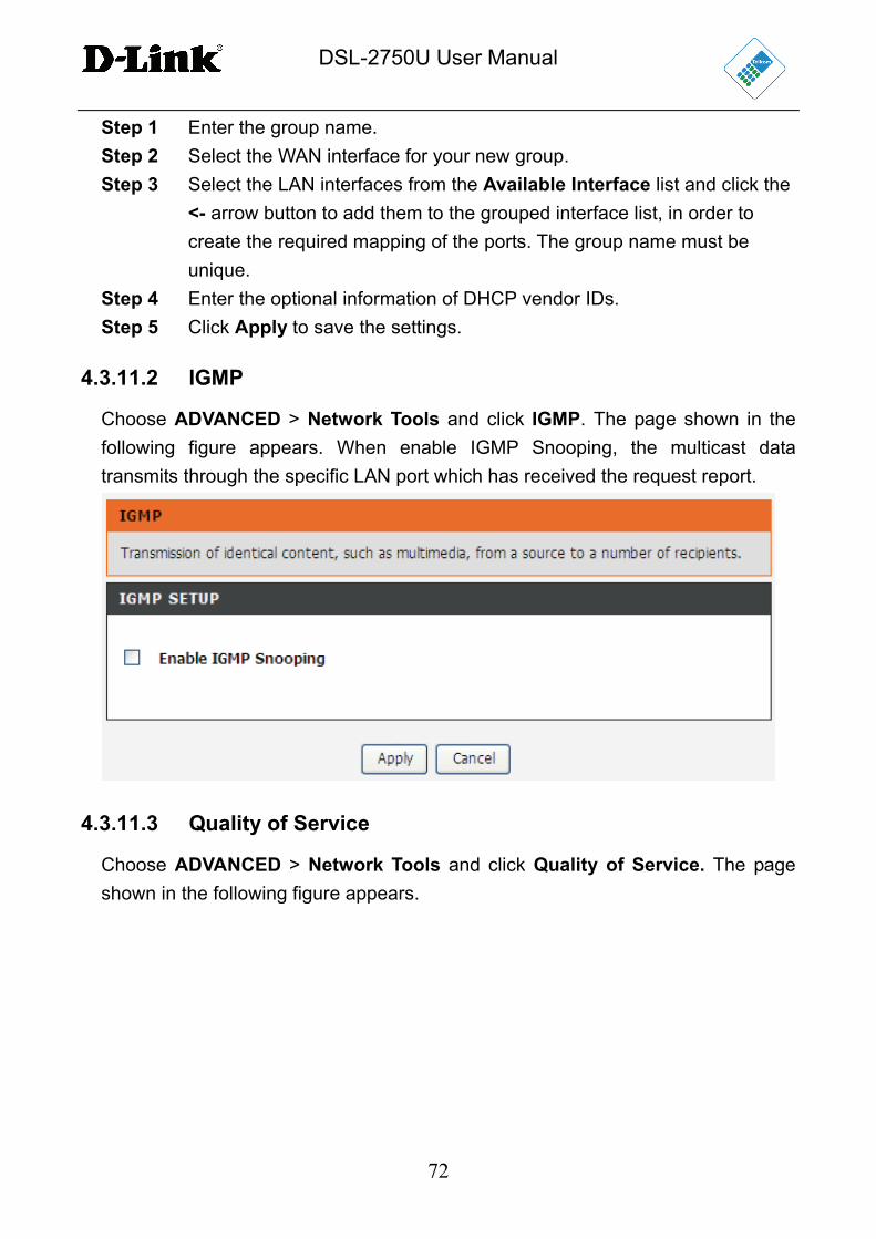
4.3.11.2 IGMP
Choose ADVANCED > Network Tools and click IGMP. The page shown in the
following figure appears. When enable IGMP Snooping, the multicast data
transmits through the specific LAN port which has received the request report.
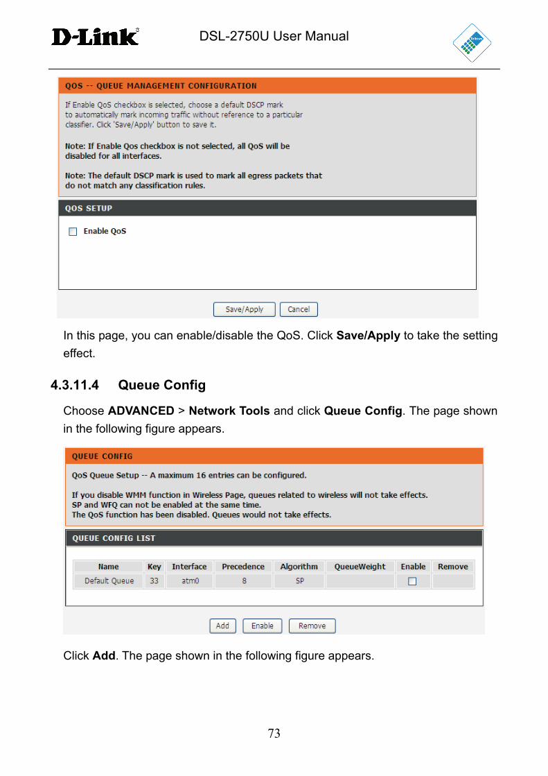
4.3.11.3 Quality of Service
Choose ADVANCED > Network Tools and click Quality of Service. The page
shown in the following figure appears.
DSL-2750U User Manual
73
In this page, you can enable/disable the QoS. Click Save/Apply to take the setting
effect.
4.3.11.4 Queue Config
Choose ADVANCED > Network Tools and click Queue Config. The page shown
in the following figure appears.
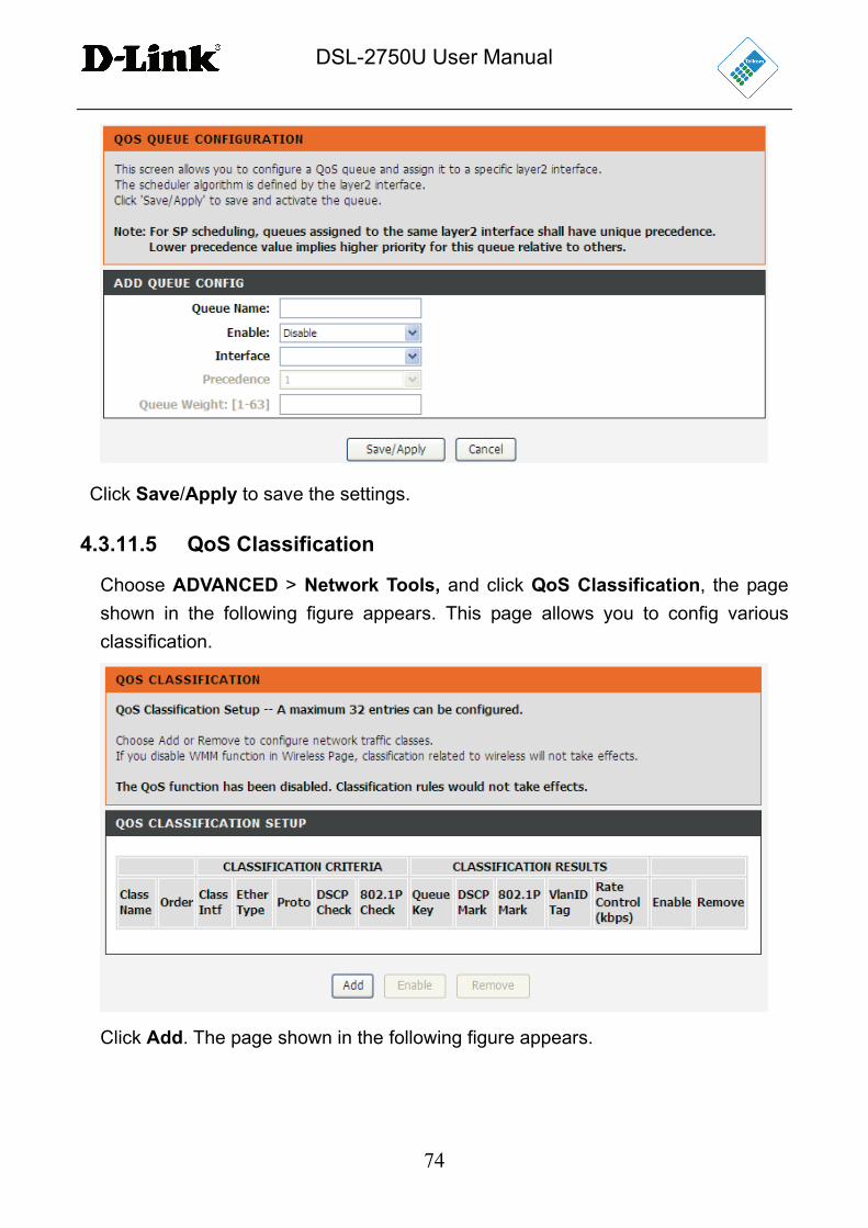
Click Add. The page shown in the following figure appears.
DSL-2750U User Manual
74
Click Save/Apply to save the settings.
4.3.11.5 QoS Classification
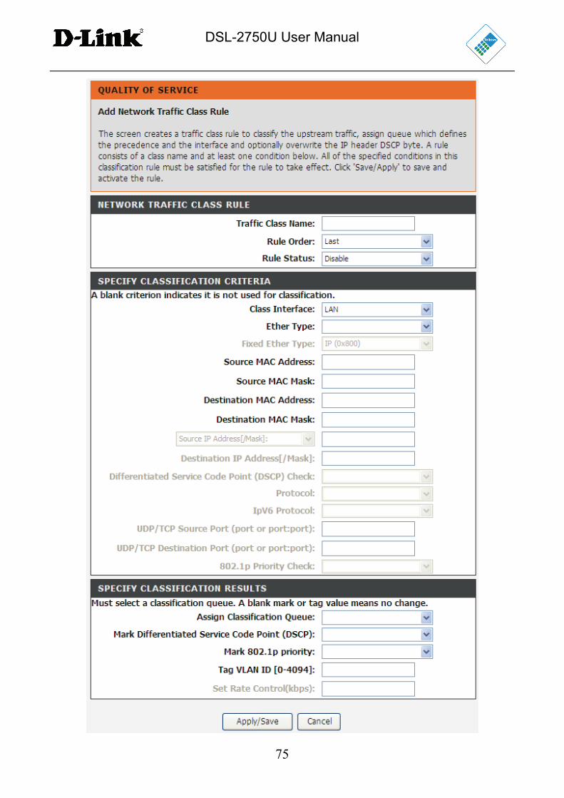
Choose ADVANCED > Network Tools, and click QoS Classification, the page
shown in the following figure appears. This page allows you to config various
classification.
Click Add. The page shown in the following figure appears.
DSL-2750U User Manual
75
DSL-2750U User Manual
76
Figure 12
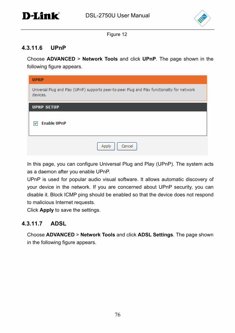
4.3.11.6 UPnP
Choose ADVANCED > Network Tools and click UPnP. The page shown in the
following figure appears.
In this page, you can configure Universal Plug and Play (UPnP). The system acts
as a daemon after you enable UPnP.
UPnP is used for popular audio visual software. It allows automatic discovery of
your device in the network. If you are concerned about UPnP security, you can
disable it. Block ICMP ping should be enabled so that the device does not respond
to malicious Internet requests.
Click Apply to save the settings.
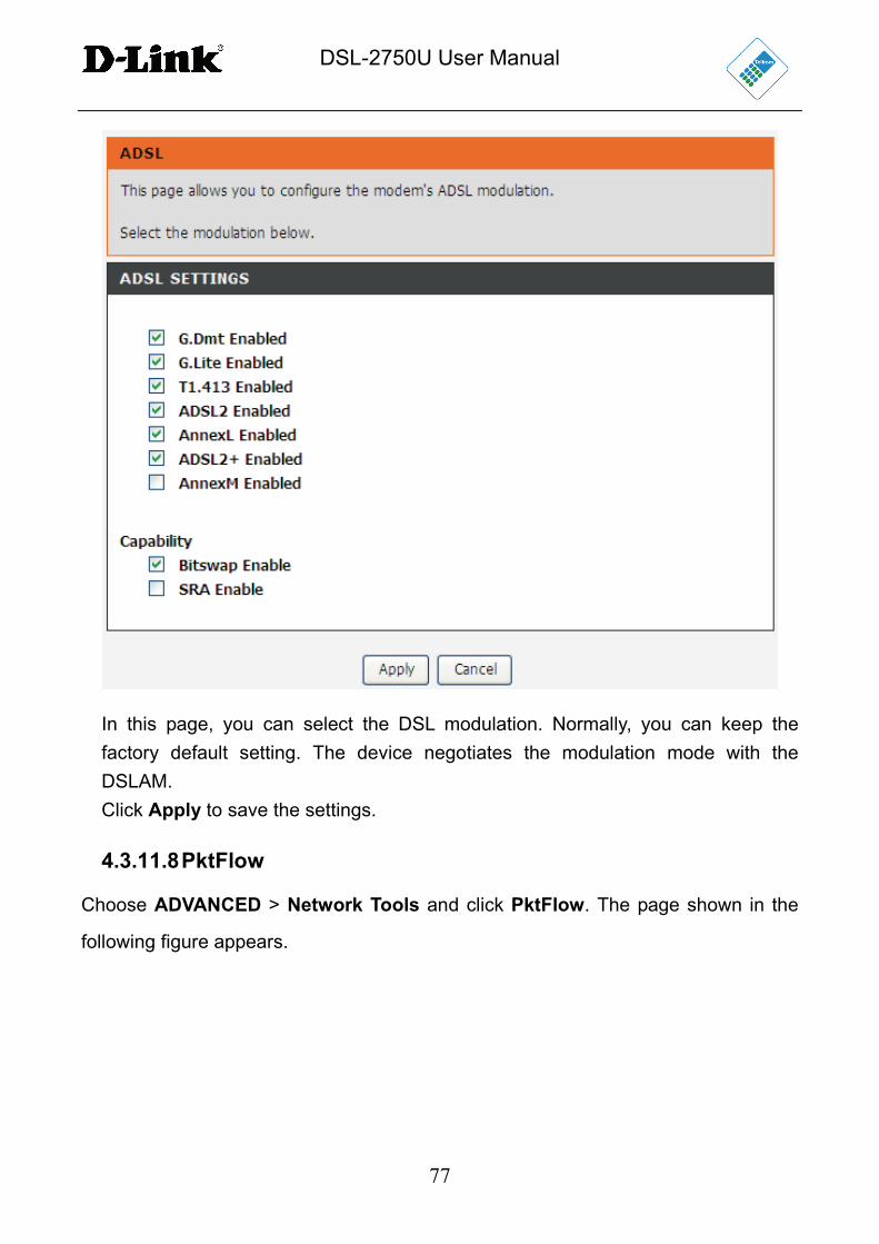
4.3.11.7 ADSL
Choose ADVANCED > Network Tools and click ADSL Settings. The page shown
in the following figure appears.
DSL-2750U User Manual
77
In this page, you can select the DSL modulation. Normally, you can keep the
factory default setting. The device negotiates the modulation mode with the
DSLAM.
Click Apply to save the settings.
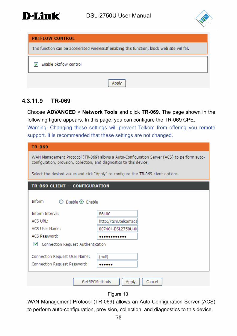
4.3.11.8 PktFlow
Choose ADVANCED > Network Tools and click PktFlow. The page shown in the
following figure appears.
DSL-2750U User Manual
78
4.3.11.9 TR-069
Choose ADVANCED > Network Tools and click TR-069. The page shown in the
following figure appears. In this page, you can configure the TR-069 CPE.
Warning! Changing these settings will prevent Telkom from offering you remote
support. It is recommended that these settings are not changed.
Figure 13
WAN Management Protocol (TR-069) allows an Auto-Configuration Server (ACS)
to perform auto-configuration, provision, collection, and diagnostics to this device.
DSL-2750U User Manual
79
In this page, you may configure the parameters such as the ACS URL, ACS
password, and connection request user name.
After finishing setting, click Apply to save and apply the settings.
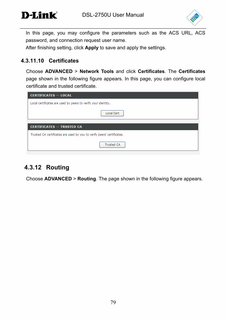
4.3.11.10 Certificates
Choose ADVANCED > Network Tools and click Certificates. The Certificates
page shown in the following figure appears. In this page, you can configure local
certificate and trusted certificate.
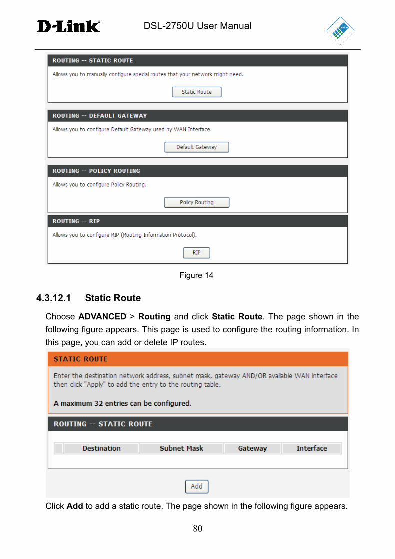
4.3.12 Routing
Choose ADVANCED > Routing. The page shown in the following figure appears.
DSL-2750U User Manual
80
Figure 14
4.3.12.1 Static Route
Choose ADVANCED > Routing and click Static Route. The page shown in the
following figure appears. This page is used to configure the routing information. In
this page, you can add or delete IP routes.
Click Add to add a static route. The page shown in the following figure appears.
DSL-2750U User Manual
81
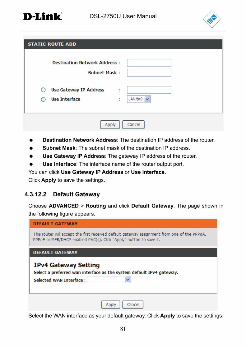
Destination Network Address: The destination IP address of the router.
Subnet Mask: The subnet mask of the destination IP address.
Use Gateway IP Address: The gateway IP address of the router.
Use Interface: The interface name of the router output port.
You can click Use Gateway IP Address or Use Interface.
Click Apply to save the settings.
4.3.12.2 Default Gateway
Choose ADVANCED > Routing and click Default Gateway. The page shown in
the following figure appears.
Select the WAN interface as your default gateway. Click Apply to save the settings.
DSL-2750U User Manual
82
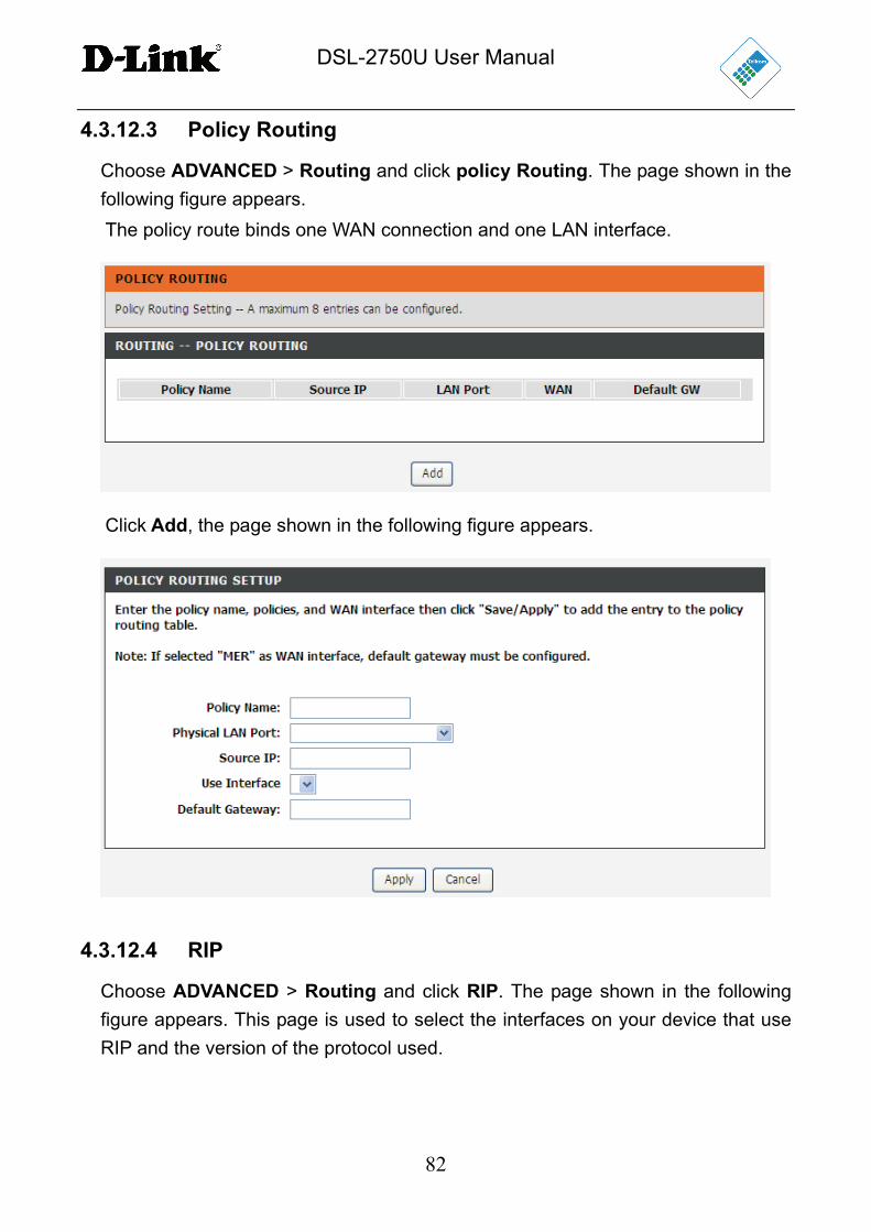
4.3.12.3 Policy Routing
Choose ADVANCED > Routing and click policy Routing. The page shown in the
following figure appears.
The policy route binds one WAN connection and one LAN interface.
Click Add, the page shown in the following figure appears.
4.3.12.4 RIP
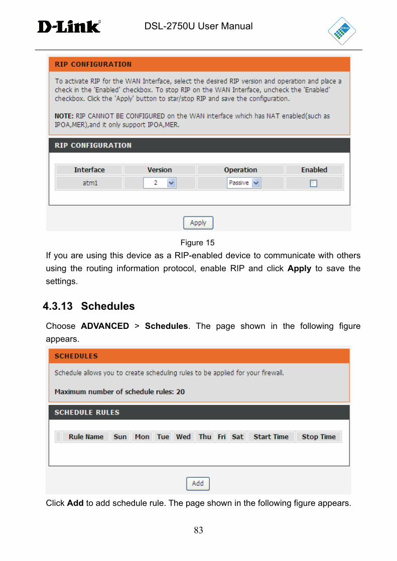
Choose ADVANCED > Routing and click RIP. The page shown in the following
figure appears. This page is used to select the interfaces on your device that use
RIP and the version of the protocol used.
DSL-2750U User Manual
83
Figure 15
If you are using this device as a RIP-enabled device to communicate with others
using the routing information protocol, enable RIP and click Apply to save the
settings.
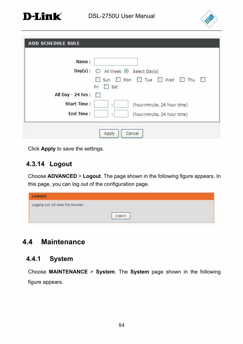
4.3.13 Schedules
Choose ADVANCED > Schedules. The page shown in the following figure
appears.
Click Add to add schedule rule. The page shown in the following figure appears.
DSL-2750U User Manual
84
Click Apply to save the settings.
4.3.14 Logout
Choose ADVANCED > Logout. The page shown in the following figure appears. In
this page, you can log out of the configuration page.
4.4 Maintenance
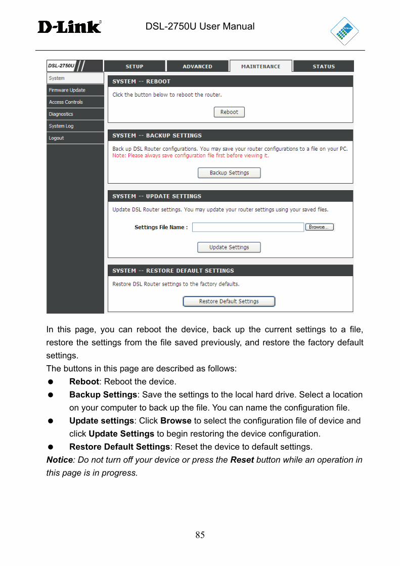
4.4.1 System
Choose MAINTENANCE > System. The System page shown in the following
figure appears.
DSL-2750U User Manual
85
In this page, you can reboot the device, back up the current settings to a file,
restore the settings from the file saved previously, and restore the factory default
settings.
The buttons in this page are described as follows:
Reboot: Reboot the device.
Backup Settings: Save the settings to the local hard drive. Select a location
on your computer to back up the file. You can name the configuration file.
Update settings: Click Browse to select the configuration file of device and
click Update Settings to begin restoring the device configuration.
Restore Default Settings: Reset the device to default settings.
Notice: Do not turn off your device or press the Reset button while an operation in this page is in progress.
DSL-2750U User Manual
86
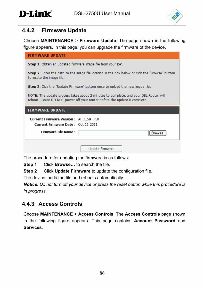
4.4.2 Firmware Update
Choose MAINTENANCE > Firmware Update. The page shown in the following
figure appears. In this page, you can upgrade the firmware of the device.
The procedure for updating the firmware is as follows:
Step 1 Click Browse… to search the file.
Step 2 Click Update Firmware to update the configuration file.
The device loads the file and reboots automatically.
Notice: Do not turn off your device or press the reset button while this procedure is in progress.
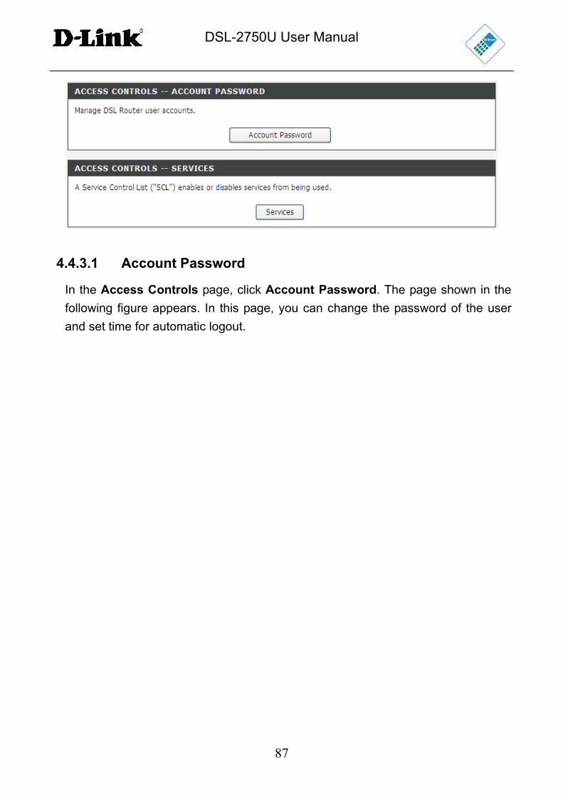
4.4.3 Access Controls
Choose MAINTENANCE > Access Controls. The Access Controls page shown
in the following figure appears. This page contains Account Password and
Services.
DSL-2750U User Manual
87
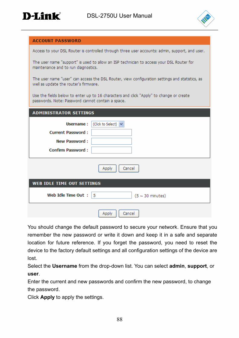
4.4.3.1 Account Password
In the Access Controls page, click Account Password. The page shown in the
following figure appears. In this page, you can change the password of the user
and set time for automatic logout.
DSL-2750U User Manual
88
You should change the default password to secure your network. Ensure that you
remember the new password or write it down and keep it in a safe and separate
location for future reference. If you forget the password, you need to reset the
device to the factory default settings and all configuration settings of the device are
lost.
Select the Username from the drop-down list. You can select admin, support, or
user.
Enter the current and new passwords and confirm the new password, to change
the password.
Click Apply to apply the settings.
DSL-2750U User Manual
89
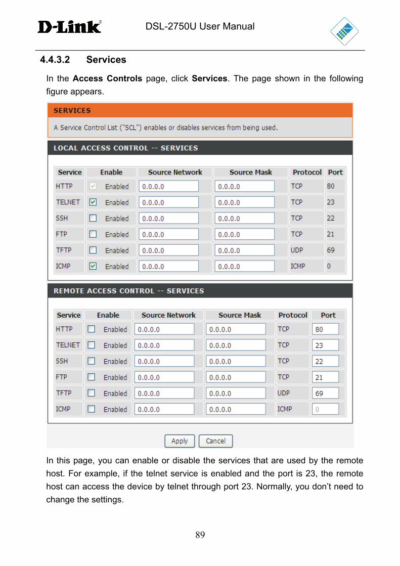
4.4.3.2 Services
In the Access Controls page, click Services. The page shown in the following
figure appears.
In this page, you can enable or disable the services that are used by the remote
host. For example, if the telnet service is enabled and the port is 23, the remote
host can access the device by telnet through port 23. Normally, you don’t need to
change the settings.
DSL-2750U User Manual
90
Select the management services that you want to enable or disable on the LAN or
WAN interface.
Click Apply to apply the settings.
Note: If you disable HTTP service, you cannot access the configuration page of the device any more.
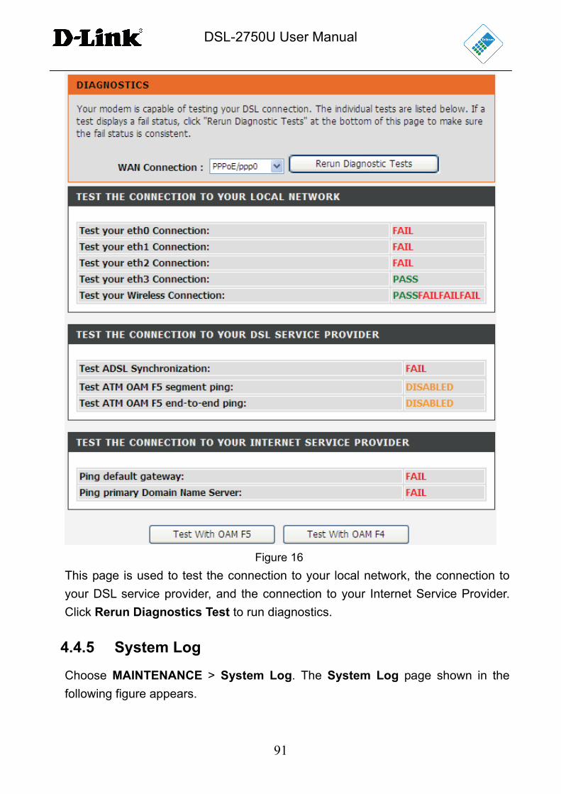
4.4.4 Diagnostics
Choose MAINTENANCE > Diagnostic. The page shown in the following figure
appears. In this page, you can test the device.
DSL-2750U User Manual
91
Figure 16
This page is used to test the connection to your local network, the connection to
your DSL service provider, and the connection to your Internet Service Provider.
Click Rerun Diagnostics Test to run diagnostics.
4.4.5 System Log
Choose MAINTENANCE > System Log. The System Log page shown in the
following figure appears.
DSL-2750U User Manual
92
This page displays event log data in a chronological manner. You can read the
event log from the local host or send it to a system log server. Available event
severity levels are as follows: Emergency, Alert, Critical, Error, Warning, Notice,
Informational and Debugging. In this page, you can enable or disable the system
log function.
The procedure for logging the events is as follows:
Step 1 Select Enable Log check box.
Step 2 Select the display mode from the Mode drop-down list.
Step 3 Enter the Server IP Address and Server UDP Port if the Mode is set to
Both or Remote.
Step 4 Click Apply to apply the settings.
Step 5 Click View System Log to view detailed information from the system
log.
DSL-2750U User Manual
93
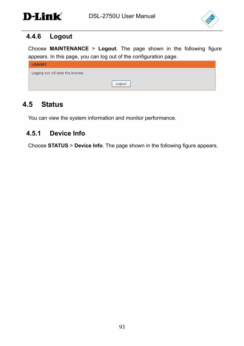
4.4.6 Logout
Choose MAINTENANCE > Logout. The page shown in the following figure
appears. In this page, you can log out of the configuration page.
4.5 Status
You can view the system information and monitor performance.
4.5.1 Device Info
Choose STATUS > Device Info. The page shown in the following figure appears.
DSL-2750U User Manual
94
The page displays the summary of the device status, including the system
information, Internet information, wireless information and local network
information.
DSL-2750U User Manual
95
4.5.2 Wireless Clients
Choose STATUS > Wireless Clients. The page shown in the following figure
appears. The page displays authenticated wireless stations and their statuses.
4.5.3 DHCP Clients
Choose STATUS > DHCP Clients. The page shown in the following page appears.
This page displays all client devices that obtain IP addresses from the device. You
can view the host name, IP address, MAC address and time expired(s).
4.5.4 Logs
Choose STATUS > Logs. The page shown in the following figure appears.
DSL-2750U User Manual
96
This page lists the system log. Click Refresh to refresh the system log shown in
the table.
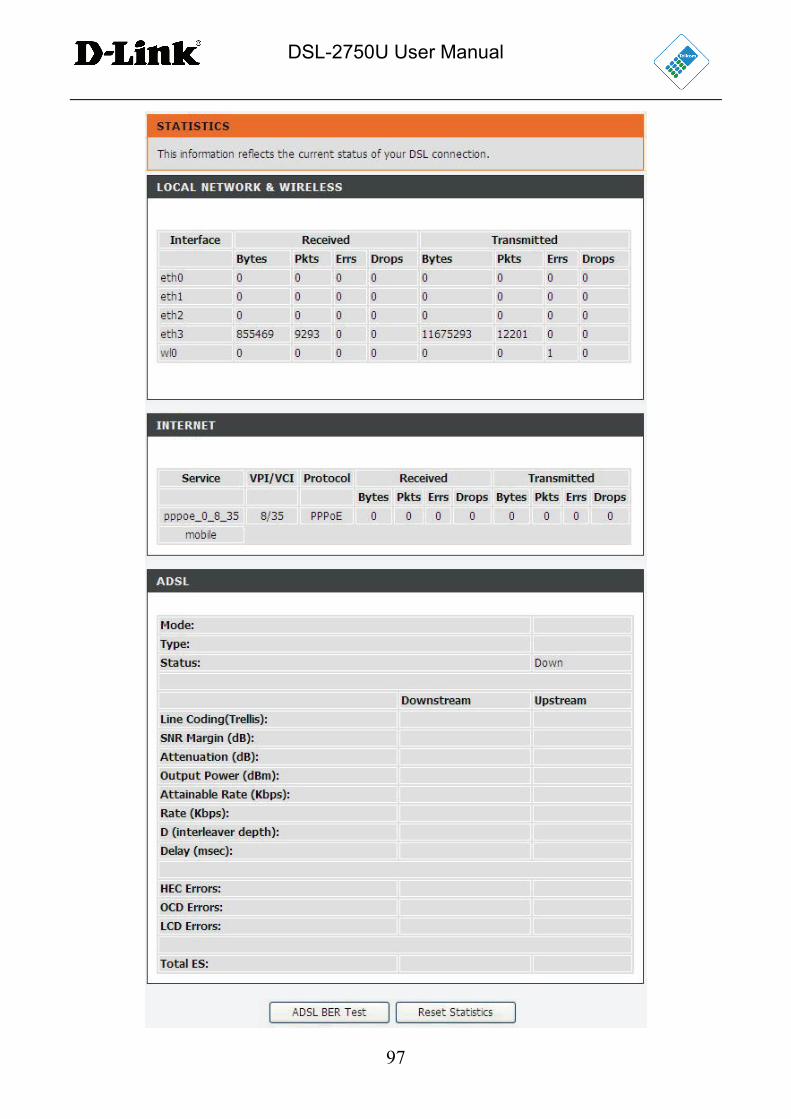
4.5.5 Statistics
Choose STATUS > Statistics. The page shown in the following figure appears.
DSL-2750U User Manual
97
DSL-2750U User Manual
98
This page displays the statistics of the network and data transfer. This information
helps technicians to identify if the device is functioning properly. The information
does not affect the function of the device.
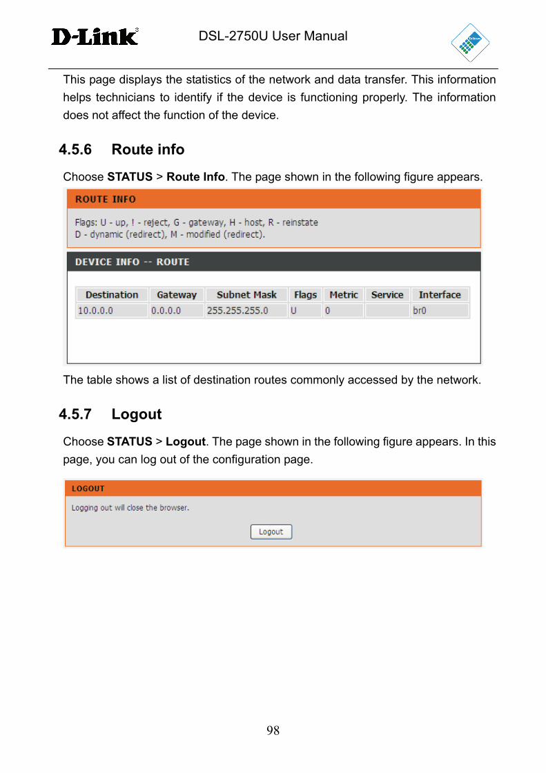
4.5.6 Route info
Choose STATUS > Route Info. The page shown in the following figure appears.
The table shows a list of destination routes commonly accessed by the network.
4.5.7 Logout
Choose STATUS > Logout. The page shown in the following figure appears. In this
page, you can log out of the configuration page.
DSL-2750U User Manual
99
5 FAQs
Question Answer
Why are all the
indicators off?
Check the connection between the power adapter
and the power socket.
Check whether the power switch is turned on.
Why is the LAN
indicator not on?
Check the following:
The connection between the device and the PC,
the hub, or the switch.
The running status of the computer, hub, or switch.
The cables that connects the device and other
devices:
– If the device connects to a computer, use the
cross over cable.
– If the device connects to a hub or a switch,
use the straight-through cable.
Why is the DSL
indicator not on?
Check the connection between the DSL interface of the
device and the socket.
Why does the
Internet access fail
when the DSL
indicator is on?
Ensure that the following information is entered
correctly:
User name and password
Why does the web
configuration page
of the device fail to
be accessed?
Choose start > Run from the desktop. Enter Ping
10.0.0.2 (the default IP address of the device) in the
DOS window.
If the web configuration page still cannot be accessed,
check the following configuration:
The type of the network cable
The connection between the device and the
computer
The TCP/IP properties of the network card of the
computer
How to restore the
default configuration
Keep the device powered on and press the RESET
button for 1 second. Then, the device automatically
DSL-2750U User Manual
100
Question Answer
after incorrect
configuration?
reboots and is restored to the factory default
configuration.
The default configuration of the device is as follows:
IP address: 10.0.0.2
Subnet mask: 255.255.255.0.
User name and password: admin/admin
6 Support
ADSL Support:
Telephone: 10210
Operatong Hours: Mon – Fri / 06h00 – 21h00,
Weekends/ 06h00 – 20h00
Router Support:
Telephone: 0860 343578 (0860 2 HELP U)
Operating Hours: Mon – Fri / 08h00 – 16h30
The Router and Power Supply/Lightning Protection Units are not themselves
guaranteed against lightning or power surges.