user instructions - logix® 420 series digital positioners ... · the logix 420 digital positioner...
TRANSCRIPT

User Instructions - Logix® 420 Series Digital Positioners FCD LGENIM0106-06 12/13
flowserve.com 1
Logix ® 420
Digital Positioner
FCD LGENIM0106-0612/13
Installation Operation
Maintenance Safety Manual
USER INSTRUCTIONS
User Instructions - Logix® 420 Series Digital Positioners FCD LGENIM0106-06 12/13
flowserve.com 2
CONTENTS
1 GENERAL INFORMATION ................................. 3 1.1 USING THIS DOCUMENT ............................................................3 1.2 TERMS CONCERNING SAFETY ......................................................3 1.3 PROTECTIVE CLOTHING .............................................................3 1.4 QUALIFIED PERSONNEL .............................................................3 1.5 VALVE AND ACTUATOR VARIATIONS .............................................3 1.6 SPARE PARTS .........................................................................3 1.7 SERVICE / REPAIR ....................................................................3 1.8 BASIC OPERATION ...................................................................4 1.9 HART ..................................................................................4 1.10 POSITION DEFINITION ...............................................................4 1.11 COMMAND INPUT AND FINAL COMMAND ......................................4 1.12 OUTER LOOP ..........................................................................5 1.13 INNER LOOP ...........................................................................5 1.14 DETAILED SEQUENCE OF POSITIONER OPERATIONS ...........................5 1.15 INNER LOOP OFFSET.................................................................5
2 SPECIFICATIONS ............................................... 6 2.1 INPUT SIGNAL ........................................................................6 2.2 AIR SUPPLY ...........................................................................6 2.3 PHYSICAL SPECIFICATIONS ..........................................................6 2.4 PNEUMATIC OUTPUT................................................................6 2.5 STROKE OUTPUT .....................................................................6 2.6 TEMPERATURE ........................................................................6 2.7 POSITIONER PERFORMANCE CHARACTERISTICS ................................6 2.8 VALVESIGHT DTM SOFTWARE SPECIFICATIONS ...............................6
3 HAZARDOUS AREA CERTIFICATIONS............ 7
4 STORAGE AND UNPACKING ............................ 8 4.1 STORAGE ..............................................................................8 4.2 UNPACKING ...........................................................................8 4.3 PRE-INSTALLATION INSPECTION ...................................................8
5 MOUNTING AND INSTALLATION ..................... 9 5.1 DIRECT MOUNTING TO VALTEK GS AND FLOWTOP ..........................9 5.2 MOUNTING TO NAMUR VALVES ............................................. 10
6 TUBING ............................................................. 11 6.1 DETERMINE AIR ACTION ......................................................... 11 6.2 CONNECT SUPPLY PORT .......................................................... 11 6.3 VENTED DESIGN .................................................................... 11 6.4 PURGING ............................................................................ 11
7 ELECTRICAL CONNECTIONS ......................... 12 7.1 ELECTRICAL TERMINALS ........................................................... 12 7.2 COMMAND INPUT (4-20 MA) CONNECTION ................................ 12 7.3 CONNECTIONS FOR INTRINSICALLY SAFE OPERATION ....................... 14
8 STARTUP .......................................................... 15 8.1 QUICK START INSTRUCTIONS .................................................... 15 8.2 LOCAL USER INTERFACE OVERVIEW ............................................ 15 8.3 CONFIGURATION SWITCH SETTINGS ............................................ 15 8.4 STROKE CALIBRATION ............................................................. 16
9 POSITIONER FUNCTIONS (NO DISPLAY REQUIRED) ....................................................... 18
9.1 LIVE MANUAL TUNING (ADJUSTING THE GAIN) ............................. 18 9.2 LOCAL CONTROL OF VALVE POSITION ......................................... 18 9.3 COMMAND SOURCE RESET ...................................................... 18 9.4 FACTORY RESET .................................................................... 18 9.5 VIEWING VERSION NUMBERS ................................................... 19
10 POSITIONER FUNCTIONS (LCD DISPLAY) .... 19 10.1 MAIN DISPLAY VIEW .............................................................. 19 10.2 MENU OVERVIEW ................................................................. 21 10.3 MENU FEATURES .................................................................. 22
11 HART COMMUNICATION ................................. 27 11.1 VALVESIGHT DTM ................................................................ 27 11.2 HART 475 HANDHELD COMMUNICATOR .................................... 27 11.3 BURST MODE ....................................................................... 27 11.4 CHANGING HART VERSIONS .................................................... 27
12 REQUIREMENTS FOR SAFETY INTEGRITY .. 28 12.1 FAIL SAFE STATE ................................................................... 28 12.2 SAFETY FUNCTION ................................................................. 28 12.3 FAIL SAFE STATE RESPONSE TIME .............................................. 28 12.4 INSTALLATION ...................................................................... 28 12.5 REQUIRED CONFIGURATION SETTINGS......................................... 28 12.6 MAXIMUM ACHIEVABLE SIL..................................................... 28 12.7 RELIABILITY DATA .................................................................. 28 12.8 LIFETIME LIMITS .................................................................... 28 12.9 PROOF TESTING .................................................................... 29 12.10 MAINTENANCE ..................................................................... 29 12.11 REPAIR AND REPLACEMENT ...................................................... 29 12.12 TRAINING REQUIREMENTS ....................................................... 29
13 MAINTENANCE AND REPAIR ......................... 30 13.1 SCHEDULED MAINTAINANCE .................................................... 30 13.2 REQUIRED TOOLS AND EQUIPMENT ............................................ 30 13.3 REPLACING A MAIN BOARD ..................................................... 30
14 TROUBLESHOOTING ....................................... 31 14.1 TROUBLESHOOTING GUIDE ...................................................... 31 14.2 STATUS CODE INDEX .............................................................. 32 14.3 STATUS CODE DESCRIPTIONS .................................................... 33 14.4 HELP FROM FLOWSERVE ......................................................... 39
15 POSITIONER DIMENSIONS.............................. 40 15.1 POSITIONER DIMENSIONS ........................................................ 40
16 HOW TO ORDER ............................................... 41 16.1 POSITIONERS ........................................................................ 41 16.2 SPARE PARTS KITS ................................................................. 41 16.3 MOUNTING KITS ................................................................... 41
INDEX ........................................................................... 42
Quick Start Instructions 15

User Instructions - Logix® 420 Series Digital Positioners FCD LGENIM0106-06 12/13
flowserve.com 3
1 GENERAL INFORMATION
1.1 Using This Document
Product users and maintenance personnel should thoroughly review this manual prior to installing, operating, or performing any maintenance on the positioner.
The following instructions are designed to assist in unpacking, installing and performing maintenance as required on Logix® 420 positioners. .
Separate Flow Control Products User Instructions cover the valve, actuator, or portions of the system and other accessories. Refer to the appropriate instructions when this information is needed. In most cases FLOWSERVE valves, actuators and accessories are designed for specific applications with regard to medium, pressure and temperature. For this reason they should not be used in other applications without first contacting the manufacturer. To avoid possible injury to personnel or damage to positioner parts, DANGER and CAUTION notes must be strictly followed. Modifying this product, substituting non-factory parts or using maintenance procedures other than outlined could drastically affect performance and be hazardous to personnel and equipment, and may void existing warranties.
1.2 Terms Concerning Safety The safety terms DANGER, CAUTION and NOTE are used in these instructions to highlight particular dangers and/or to provide additional information on aspects that may not be readily apparent. NOTE: Indicates and provides additional technical information, which may not be very obvious even to qualified personnel.
CAUTION: Indicates that minor personal injury and/or property damage can occur if proper precautions are not taken.
DANGER: Indicates that death, severe personal injury and/or substantial property damage can occur if proper precautions are not taken.
Compliance with other, not particularly emphasized notes, with regard to assembly, operation and maintenance and technical documentation (e.g., in the operating instruction, product documentation or on the product itself) is essential in order to avoid faults, which in themselves might directly or indirectly cause severe personal injury or property damage.
1.3 Protective Clothing
FLOWSERVE positioners use high pressure gas to operate. Use eye protection when working around pressurized equipment. Follow proper procedures for working with natural gas if it is used.
DANGER: Standard industry safety practices must be adhered to when working on this or any process control product. Specifically, personal protective equipment must be used as warranted.
1.4 Qualified Personnel Qualified personnel are people who, on account of their training, experience, instruction and their knowledge of relevant standards, specifications, accident prevention regulations and operating conditions, have been authorized by those responsible for the safety of the plant to perform the necessary work and who can recognize and avoid possible dangers. In unpacking, installing and performing maintenance as required on FLOWSERVE products, product users and maintenance personnel should thoroughly review this manual prior to installing, operating or performing any maintenance.
1.5 Valve and Actuator Variations These instructions cannot claim to cover all details of all possible product variations, nor can they provide information for every possible example of installation, operation or maintenance. This means that the instructions normally include only the directions to be followed by qualified personal where the product is being used for its defined purpose. If there are any uncertainties in this respect particularly in the event of missing product-related information, clarification must be obtained via the appropriate Flowserve sales office.
1.6 Spare Parts Use only FLOWSERVE original spare parts. FLOWSERVE cannot accept responsibility for any damages that occur from using spare parts or fastening materials from other manufactures. If FLOWSERVE products (especially sealing materials) have been in storage for longer periods check these for corrosion or deterioration before using these products. See section 4 STORAGE AND UNPACKING more information.
1.7 Service / Repair To avoid possible injury to personnel or damage to products, safety terms must be strictly adhered to. Modifying this product, substituting non-factory parts, or using maintenance procedures other than outlined in this instruction could drastically affect performance and be hazardous to personnel and equipment, and may void existing warranties. Between actuator and valve there are moving parts. To avoid injury FLOWSERVE provides pinch-point-protection in the
User Instructions - Logix® 420 Series Digital Positioners FCD LGENIM0106-06 12/13
flowserve.com 4
form of cover plates, especially where side-mounted positioners are fitted. If these plates are removed for inspection, service or repair special attention is required. After completing work the cover plates must be refitted.
Logix 420 positioner repair is limited to the replacement of sub-assemblies and circuit boards with FLOWSERVE-manufactured replacements as outlined in this manual.
DANGER: Substitution of with non-factory positioner
components may impair intrinsic safety.
CAUTION: Before products are returned to FLOWSERVE for repair or service, FLOWSERVE must be provided with a certificate which confirms that the product has been decontaminated and is clean. FLOWSERVE will not accept deliveries if a certificate has not been provided (a form can be obtained from FLOWSERVE).
Apart from the operating instructions and the obligatory accident prevention directives valid in the country of use, all recognized regulations for safety and good engineering practices must be followed.
PRINCIPLES OF OPERATION 1.8 Basic Operation The Logix 420 digital positioner is a two-wire 4-20 mA input digital valve positioner which uses the HART protocol to allow two-way remote communications. The positioner is completely powered by the 4-20 mA input signal. Start-up current must be at least 3.8 mA. The positioner is configurable through the local user interface, hand-held or DTM. The Logix 420 positioner can control single-acting pneumatic actuators with linear or rotary mountings.
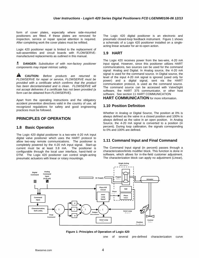
The Logix 420 digital positioner is an electronic and pneumatic closed-loop feedback instrument. Figure 1 shows a schematic of a Logix 420 positioner installed on a single-acting linear actuator for air-to-open action.
1.9 HART The Logix 420 receives power from the two-wire, 4-20 mA input signal. However, since this positioner utilizes HART communications, two sources can be used for the command signal: Analog and Digital. In Analog source, the 4-20 mA signal is used for the command source. In Digital source, the level of the input 4-20 mA signal is ignored (used only for power) and a digital signal, sent via the HART communication protocol, is used as the command source. The command source can be accessed with ValveSight software, the HART 375 communicator, or other host software. See section 11 HART COMMUNICATION
HART COMMUNICATION for more information.
1.10 Position Definition Whether in Analog or Digital Source, The position at 0% is always defined as the valve in a closed position and 100% is always defined as the valve in an open position. In Analog Source, the 4-20 mA signal is converted to a position (in percent). During loop calibration, the signals corresponding to 0% and 100% are defined.
1.11 Command Input and Final Command The Command Input signal (in percent) passes through a characterization/limits modifier block. This function is done in software, which allows for in-the-field customer adjustment. The characterization block can apply no adjustment (Linear),
one of several pre-defined characterization curve
Figure 1: Principles of Operation of Logix 420
Piezo
Valve
Hall
Sensor
Air Supply Poppet
Valve
Single Acting
Pilot Relay
Piezo
Voltage
Piezo Kill
Circuit
Inner
Loop
Spool
Control
Position
Feedback
Control
Valve
Actuator
Final
Command
Command
Input
Signal
Characterization,
Soft Limits,
Tight Shutoff
Digital
Command
Input
Analog
Command
Input
(4-20 mA)
Output
Percentage
+
+
+
Σ
P
I
D
Σ + _
Inner-Loop
Output
+
_
Σ
Inner-Loop
Offset
User Instructions - Logix® 420 Series Digital Positioners FCD LGENIM0106-06 12/13
flowserve.com 5
adjustments (including several Equal Percent), or a 21-point Custom Characterization curve adjustment. In Linear mode, the input signal is passed straight through to the control algorithm in a 1:1 transfer. In Equal Percent (=%) mode, the input signal is mapped to a standard rangeability equal percent curve. If Custom Characterization is enabled, the input signal is mapped to a custom, user-defined 21-point output curve. The custom user-defined 21-point output curve is defined using a handheld or ValveSight software. In addition, two user-defined features, Soft Limits and Tight Shutoff may affect the position. The actual command being used to position the stem after the evaluation of characterization curves and user limits, is called the Final Command.
1.12 Outer Loop The Logix 420 uses a two-stage, stem-positioning algorithm. The two stages consist of an inner-loop (pilot relay control) and an outer-loop (stem position control). Referring again to Figure 1, a stem position sensor provides a measurement of the stem movement. The Final Command is compared against the Stem Position. If any deviation exists, the control algorithm sends a signal to the inner-loop control to move the relay in a direction, depending upon the deviation. The inner-loop then quickly adjusts the spool position. The actuator pressures change and the stem begins to move. The stem movement reduces the deviation between Final Command and Stem Position. This process continues until the deviation goes to zero.
1.13 Inner Loop The inner-loop controls the position of the relay valve by means of a driver module. The driver module consists of a temperature-compensated hall-effect sensor and a Piezo valve pressure modulator. The Piezo valve pressure modulator controls the air pressure under a diaphragm by means of a Piezo beam bender. The Piezo beam deflects in response to an applied voltage from the inner-loop electronics. As the voltage to the Piezo valve increases, the Piezo beam bends, closing off against a nozzle causing the pressure under the diaphragm to increase. As the pressure under the diaphragm increases or decreases, the poppet valve moves up or down respectively. The Hall effect sensor transmits the position of the poppet back to the inner-loop electronics for control purposes.
1.14 Detailed Sequence of Positioner Operations
A more detailed example explains the control function. Assume the unit is configured as follows:
Unit is in Analog command source.
Custom characterization is disabled (therefore characterization is Linear).
No soft limits enabled. No tight shutoff (MPC) set.
Valve has zero deviation with a present input signal of 12 mA.
Loop calibration: 4 mA = 0% command, 20 mA = 100% command.
Actuator is tubed and positioner is configured air-to-open.
Given these conditions, 12 mA represents a Command source of 50 percent. Custom characterization is disabled so the command source is passed 1:1 to the Final Command. Since zero deviation exists, the stem position is also at 50 percent. With the stem at the desired position, the poppet valve will be at a middle position that balances the pressures and spring force in the actuator. This is commonly called the null or balanced poppet position. Assume the input signal changes from 12 mA to 16 mA. The positioner sees this as a command source of 75 percent. With Linear characterization, the Final Command becomes 75 percent. Deviation is the difference between Final Command and Stem Position: Deviation = 75% - 50% = +25%, where 50 percent is the present stem position. With this positive deviation, the control algorithm sends a signal to move the poppet up from its present position. As the poppet moves, the supply air is applied to the bottom of the actuator. This new pressure differential causes the stem to start moving towards the desired position of 75 percent. As the stem moves, the Deviation begins to decrease. The control algorithm begins to reduce the poppet opening. This process continues until the Deviation goes to zero. At this point, the poppet will be back in its null or balanced position. Stem movement will stop and the desired stem position is now achieved.
1.15 Inner Loop Offset The position of the poppet at which the pressure and springs are balanced, holding the valve position in a steady state, is called the Inner Loop Offset. The controlling algorithm uses this value as a reference in determining the Piezo voltage. This parameter is important for proper control and is optimized and set automatically during stroke calibration.
Vent
User Instructions - Logix® 420 Series Digital Positioners FCD LGENIM0106-06 12/13
flowserve.com 6
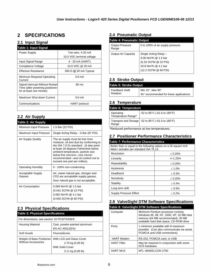
2 SPECIFICATIONS
2.1 Input Signal
Table 1: Input Signal
Power Supply Two-wire, 4-20 mA
10.0 VDC terminal voltage
Input Signal Range 4 - 20 mA (HART)
Compliance Voltage 10.0 VDC @ 20 mA
Effective Resistance 500 Ω @ 20 mA Typical
Minimum Required Operating Current
3.8 mA
Signal Interrupt Without Restart Time (after powering positioner for at least one minute)
80 ms
Maximum Shut-down Current 3.6 mA
Communications HART protocol
2.2 Air Supply
Table 2: Air Supply
Minimum Input Pressure 1.5 Bar (22 PSI)
Maximum Input Pressure Single Acting Relay – 6 Bar (87 PSI)
Air Supply Quality The air supply must be free from
moisture, oil and dust by conforming to the ISA 7.0.01 standard. (A dew point at least 18 degrees Fahrenheit below ambient temperature, particle size below five microns—one micron recommended—and oil content not to exceed one part per million).
Operating Humidity 0 - 100% non-condensing
Acceptable Supply Gasses
Air, sweet natural gas, nitrogen and CO2 are acceptable supply gasses.
Sour natural gas is not acceptable.
Air Consumption 0.069 Nm³/h @ 1.5 bar
(0.041 SCFM @ 22 PSI)
0.082 Nm³/h @ 4.1 bar
(0.050 SCFM @ 60 PSI)
2.3 Physical Specifications
Table 3: Physical Specifications
For dimensions, see section 15 POSITIONER .
Housing Material Cast, powder-painted aluminum
EN AC-AlSi12(Fe)
Soft Goods Fluorosilicone
Weight of Base Positioner Without Accessories
With LCD and Glass Cover
2.70 kg (5.95 lb)
With Solid Cover
3.11 kg (6.85 lb)
2.4 Pneumatic Output
Table 4: Pneumatic Output
Output Pressure Range
0 to 100% of air supply pressure.
Output Air Capacity Single Acting Relay –
9.06 Nm³/h @ 1.5 bar
(5.33 SCFM @ 22 PSI)
20.8 Nm³/h @ 4.1 bar
(12.2 SCFM @ 60 PSI)
2.5 Stroke Output
Table 5: Stroke Output
Feedback shaft Rotation
Min 15°, Max 90°
45° recommended for linear applications.
2.6 Temperature
Table 6: Temperature
Operating Temperature Range*
-52 to 85°C (-61.6 to 185°F)
Transport and Storage Range
-52 to 85°C (-61.6 to 185°F)
*Reduced performance at low temperatures.
2.7 Positioner Performance Characteristics
Table 7: Performance Characteristics
Better than or equal to the following values on a 25 square inch Mark I actuator per standard ISA 75.13.
Resolution 0.25%
Linearity +/-1.25%
Repeatability 0.25%
Hysteresis 1.0%
Deadband 0.3%
Sensitivity 0.25%
Stability 0.4%
Long term drift 0.5%
Supply Pressure Effect 0.2%
2.8 ValveSight DTM Software Specifications
Table 8: ValveSight DTM Software Specifications
Computer Minimum Pentium processor running Windows 95, 98, NT, 2000, XP, 32 MB total memory (64 MB recommended), 30 MB available hard disk space, CD-ROM drive
Ports 1 minimum available with 8 maximum
possible. (Can also communicate via serial,
PCMCIA and USB connections)
HART Modem RS-232, PCMCIA card, or USB
HART Filter May be required in conjunction with some DCS hardware.
HART MUX MTL 4840/ELCON 2700
User Instructions - Logix® 420 Series Digital Positioners FCD LGENIM0106-06 12/13
flowserve.com 7
3 HAZARDOUS AREA CERTIFICATIONS
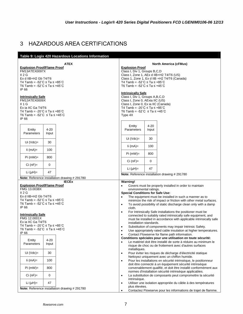
Table 9: Logix 420 Hazardous Locations Information
ATEX Explosion Proof/Flame Proof FM13ATEX0097X II 2 G Ex d IIB+H2 Gb T4/T6 T4 Tamb = -52˚C ≤ Ta ≤ +85˚C T6 Tamb = -52˚C ≤ Ta ≤ +45˚C IP 66 Intrinsically Safe FM12ATEX0009X II 1 G Ex ia IIC Ga T4/T6 T4 Tamb = -20˚C ≤ Ta ≤ +85˚C T6 Tamb = -52˚C ≤ Ta ≤ +45˚C IP 66
Entity Parameters
4-20 Input
Ui (Vdc)= 30
Ii (mA)= 100
Pi (mW)= 800
Ci (nF)= 0
Li (µH)= 47
Note: Reference installation drawing # 291780
North America (cFMus)
Explosion Proof Class I, Div 1, Groups B,C,D Class I, Zone 1, AEx d IIB+H2 T4/T6 (US) Class 1, Zone 1, Ex d IIB +H2 T4/T6 (Canada) T4 Tamb = -52˚C ≤ Ta ≤ +85˚C T6 Tamb = -52˚C ≤ Ta ≤ +45˚C Intrinsically Safe Class I, Div 1, Groups A,B,C,D Class I, Zone 0, AExia IIC (US) Class I, Zone 0, Ex ia IIC (Canada) T4 Tamb = -20˚C ≤ Ta ≤ +85˚C T6 Tamb = -52˚C ≤ Ta ≤ +45˚C Type 4X
Entity Parameters
4-20 Input
Ui (Vdc)= 30
Ii (mA)= 100
Pi (mW)= 800
Ci (nF)= 0
Li (µH)= 47
Note: Reference installation drawing # 291780
IECEx Explosion Proof/Flame Proof FMG 13.0038X II 2 G Ex d IIB+H2 Gb T4/T6 T4 Tamb = -52˚C ≤ Ta ≤ +85˚C T6 Tamb = -52˚C ≤ Ta ≤ +45˚C IP 66 Intrinsically Safe FMG 12.0001X Ex ia IIC Ga T4/T6 T4 Tamb = -20˚C ≤ Ta ≤ +85˚C T6 Tamb = -52˚C ≤ Ta ≤ +45˚C IP 66
Entity Parameters
4-20 Input
Ui (Vdc)= 30
Ii (mA)= 100
Pi (mW)= 800
Ci (nF)= 0
Li (µH)= 47
Note: Reference installation drawing # 291780
Warning!
Covers must be properly installed in order to maintain environmental ratings.
Special Conditions for Safe Use:
The equipment must be installed in such a manner as to minimize the risk of impact or friction with other metal surfaces.
To avoid possibility of static discharge clean only with a damp cloth.
For Intrinsically Safe installations the positioner must be connected to suitably rated intrinsically safe equipment, and must be installed in accordance with applicable intrinsically safe installation standards.
Substitution of components may impair Intrinsic Safety.
Use appropriately rated cable insulation at higher temperatures.
Contact Flowserve for flame path information. Conditions spéciales pour une utilisation en toute sécurité:
Le matériel doit être installé de sorte à réduire au minimum le risque de choc ou de frottement avec d'autres surfaces métalliques.
Pour éviter les risques de décharge d'électricité statique Nettoyez uniquement avec un chiffon humide.
Pour les installations en sécurité intrinsèque, le positionneur doit être connecté à un équipement sécurité intrinsèque convenablement qualifié, et doit être installé conformément aux normes d'installation sécurité intrinsèque applicables.
La substitution de composants peut compromettre la sécurité intrinsèque.
Utiliser une isolation appropriée du câble à des températures plus élevées.
Contactez Flowserve pour les informations de trajet de flamme.
User Instructions - Logix® 420 Series Digital Positioners FCD LGENIM0106-06 12/13
flowserve.com 8
4 STORAGE AND UNPACKING
4.1 Storage FLOWSERVE Control valve packages (a control valve and its instrumentation) are typically well protected from corrosion. Nevertheless FLOWSERVE products must be stored in a clean, dry environment such as an enclosed building that affords environmental protection. Heating is not required. Control valve packages must be stored on suitable skids, not directly on the floor. The storage location must also be free from flooding, dust, dirt, etc. Plastic caps are fitted to protect the flange faces and positioner ports to prevent the ingress of foreign materials. These caps should not be removed until the valve or positioner is actually mounted into the system. If FLOWSERVE products (especially sealing materials) have been in storage for longer periods check these for corrosion or deterioration before using these products. Fire protection for FLOWSERVE products must be provided by the end user.
4.2 Unpacking While unpacking the valve and/or Logix 500MD+ positioner, check the packing list against the materials received. Lists describing the system and accessories are included in each shipping container. In the event of shipping damage, contact the shipper immediately. Should any problems arise, contact a Flowserve Flow Control Division representative.
4.3 Pre-installation Inspection When installing a positioner, verify the shaft has not been damaged and that the plugs and cover are in place. The plugs keep debris and moisture from damaging the internal components of the positioner. If the positioner has been contaminated, clean the positioner components gently with a soft damp cloth. Some components may be removed for better access. See section 13 MAINTENANCE AND REPAIR. Check connectors to ensure that no debris is present. Port screens can be removed with a flat screwdriver for access to internal passages.

User Instructions - Logix® 420 Series Digital Positioners FCD LGENIM0106-06 12/13
flowserve.com 9
5 MOUNTING AND INSTALLATION
5.1 Direct Mounting to Valtek GS and FlowTop
Refer to Figure 2: Valtek GS and FlowTop Mounting. 1 Assemble the take-off pin to the take-off plate and
mount the take-off plate to the valve stem using the two screws. See Table 10: FlowTop and GS Take-Off Plate and Pin Configuration for proper plate and pin
orientation.
2 Place the actuator O-ring.
3 Ensure the 1/16 NPT plug for the control port (if present) has been removed.
4 Place the positioner on the actuator, ensuring the take-off pin is inside the follower arm slot. Adjust the follower arm as needed.
NOTE: The feedback shaft has a clutch mechanism that allows for over-rotation of the shaft for easy adjustments. Just move the follower arm to the desired location.
5 Use the actuator screws to secure the positioner in
place.
6 Connect regulated air supply to appropriate port in manifold. See section 6 TUBING.
7 Connect the power to the 4-20 mA terminals. See
section 7 ELECTRICAL CONNECTIONS. 8 Remove main cover and locate DIP switches and
QUICK-CAL/ACCEPT button. 9 Refer to sticker on main board cover and set DIP
switches accordingly. See section 8 STARTUP.
10 Press the QUICK-CAL/ACCEPT button for three to four
seconds or until the positioner begins to move. The positioner will now perform a stroke calibration.
CAUTION: Performing a Stroke Calibration will cause full
movement of the valve in both directions. 11 If the calibration was successful the green LED will blink
GGGG or GGGY and the valve will be in control mode.
12 If calibration fails, as indicated by a RGGY blink code, retry the calibration. If it still fails, the feedback values were exceeded and the arm must be adjusted away from the positioner’s limits. Rotate the feedback shaft so that the full free travel of the feedback shaft is in the range of the actuator movement. Optionally, continue to attempt the calibration. Each calibration attempt adjusts the acceptable limits and it should pass eventually.
CAUTION: Remember to remove the air supply before re-adjusting follower arm.
NOTE: If mounted properly, the follower arm should be horizontal when the valve is at 50% stroke and should move approximately ±30° from horizontal over the full stroke of the valve.
NOTE: To virtually eliminate any non-linearity due to linkage geometry, use the Linearization feature on the Custom Characterization page of the DTM.
Actuator Screws
Take-Off Plate
Take-Off Pin
Take-Off Plate Screws
Actuator O-ring
Figure 2: Valtek GS and FlowTop Mounting
User Instructions - Logix® 420 Series Digital Positioners FCD LGENIM0106-06 12/13
flowserve.com 10
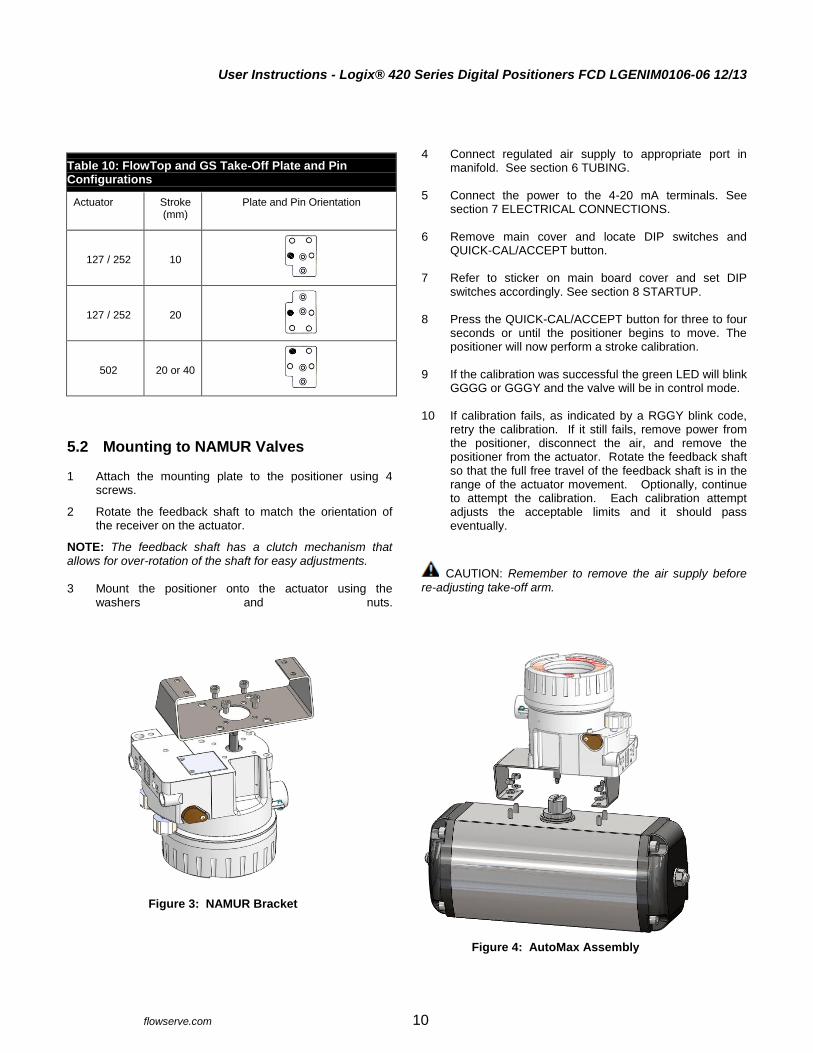
Table 10: FlowTop and GS Take-Off Plate and Pin Configurations
Actuator Stroke (mm)
Plate and Pin Orientation
127 / 252 10
127 / 252 20
502 20 or 40
5.2 Mounting to NAMUR Valves
1 Attach the mounting plate to the positioner using 4 screws.
2 Rotate the feedback shaft to match the orientation of the receiver on the actuator.
NOTE: The feedback shaft has a clutch mechanism that allows for over-rotation of the shaft for easy adjustments. 3 Mount the positioner onto the actuator using the
washers and nuts.
4 Connect regulated air supply to appropriate port in manifold. See section 6 TUBING.
5 Connect the power to the 4-20 mA terminals. See
section 7 ELECTRICAL CONNECTIONS. 6 Remove main cover and locate DIP switches and
QUICK-CAL/ACCEPT button. 7 Refer to sticker on main board cover and set DIP
switches accordingly. See section 8 STARTUP. 8 Press the QUICK-CAL/ACCEPT button for three to four
seconds or until the positioner begins to move. The positioner will now perform a stroke calibration.
9 If the calibration was successful the green LED will blink
GGGG or GGGY and the valve will be in control mode.
10 If calibration fails, as indicated by a RGGY blink code, retry the calibration. If it still fails, remove power from the positioner, disconnect the air, and remove the positioner from the actuator. Rotate the feedback shaft so that the full free travel of the feedback shaft is in the range of the actuator movement. Optionally, continue to attempt the calibration. Each calibration attempt adjusts the acceptable limits and it should pass eventually.
CAUTION: Remember to remove the air supply before re-adjusting take-off arm.
Figure 3: NAMUR Bracket
Figure 4: AutoMax Assembly

User Instructions - Logix® 420 Series Digital Positioners FCD LGENIM0106-06 12/13
flowserve.com 11
6 TUBING
After mounting has been completed, tube the positioner to the actuator using the appropriate compression fitting connectors. For best performance, use 10 mm (3/8 inch) tubing for 645 square cm (100 square inch) actuators or larger.
6.1 Determine Air Action The port labeled “Out” delivers air when an air supply is present and the relay is energized. This port should be tubed to the pneumatic side of the actuator (the side that would result in the air compressing the actuator spring). When tubed this way, the spring is designed to return the valve to the fail safe state should supply air or power to the unit fail. If air from the output should open the valve, set the Air Action configuration switch on the positioner to Air-to-Open, otherwise set it to Air-to-Close. The Air-to-Open and Air-to-Close selection is determined by the actuator assembly, not the software.
6.2 Connect Supply Port
The positioner ports are threaded with 1/4 NPTF. The direct mount output is 1/16 NPTF. In order to maintain the recommended air quality, a coalescing filter should always be installed in the supply gas line. An air filter is highly recommended for all applications where dirty air is a possibility. The positioner passage ways are equipped with small filters, which remove medium and coarse size dirt from the pressurized air. If necessary, they are easily accessible for cleaning. In applications where the supply pressure is higher than the maximum actuator pressure rating a supply regulator is required to lower the pressure to the actuator’s maximum rating.
6.3 Vented Design A standard Logix 420 positioner is vented directly to the atmosphere. When supply air is substituted with sweet natural gas, piping must be used to route the exhausted natural gas to a safe environment. The exhaust port is located on the bottom of the positioner. The port is tapped with either ¼ NPTF threads and covered with a protective cap. To control vented gas, remove the cap and connect the necessary tubing/piping to this port. This piping system may cause some positioner back pressure. The maximum allowable back pressure from the exhaust port is 0.14 barg (2.0 PSIG). For output flow rates, see section 2.4 Pneumatic Output.
CAUTION: The back pressure in the main housing must
never rise above 0.14 barg (2.0 PSIG). This could cause the positioner to become unresponsive under some circumstances.
6.4 Purging Purging is intended to supply the non-pressurized side of a single acting actuator with instrument air. This helps prevent air from the environment (which may be salty, dirty or humid) from corroding the springs and other actuator components. Purging uses exhaust air from the positioner to flush the spring side of the actuator. Tubing Configuration - Tube the Exhaust port with a “T” where one line goes to the non-pressurized side of the positioner and the second line goes to the atmosphere. Install an exhaust plug on the second line to prevent debris from entering the tubing.
Exhaust (Piezo and Actuator) (0.14 barg (2 psi) Max)
Figure 5: Pneumatic Ports
Out (Direct Mount Control) Out (Control) In (Supply)

User Instructions - Logix® 420 Series Digital Positioners FCD LGENIM0106-06 12/13
flowserve.com 12
7 ELECTRICAL CONNECTIONS
7.1 Electrical Terminals
Figure 6: Terminal Diagram
7.2 Command Input (4-20 mA) Connection The Logix 420 is reverse polarity protected, however, verify polarity when making field termination connection. Wire 4-20 mA current source to the input terminal labeled “HART 4-20mA INPUT”. See Figure 6: Terminal Diagram. Depending on the current source, a HART filter may be required. See 14.1 Troubleshooting Guide.
7.2.1 Compliance Voltage
Output compliance voltage refers to the voltage limit the current source can provide. A current loop system consists of the current source, wiring resistance, barrier resistance (if present), and the Logix 420 impedance. The Logix 420 requires that the current loop system allow for a 10 VDC drop across the positioner at maximum loop current. The operating current range is from 3.8 to 24 mA. In order to determine if the loop will support the Logix 420, perform the calculation in Equation 1. The Available Voltage must be greater than 10VDC in order to support the Logix 420. Also, see Table 1: Input Signal. Equation 1
( ) ( )
Example:
( )
The available voltage (12.5 V) is greater than the required voltage (10.0 V) therefore; this system will support the Logix 420. The Logix 420 has an input resistance equivalent to 500 Ω at a 20 mA input current.
CAUTION: The current must always be limited for 4-20
mA operation. Never connect a voltage source directly across the Logix 420 terminals. This could cause permanent circuit board damage.
HART 4-20
mA Inp
ut -
Housing EARTH Terminal
Internal External

User Instructions - Logix® 420 Series Digital Positioners FCD LGENIM0106-06 12/13
flowserve.com 13
Figure 7: Compliance Voltage
7.2.2 Cable Requirements
The Logix 420 digital positioner utilizes the HART Communication protocol. This communication signal is superimposed on the 4-20 mA current signal. The two frequencies used by the HART protocol are 1200 Hz and 2200 Hz. In order to prevent distortion of the HART communication signal, cable capacitance and cable length restrictions must be calculated. The cable length must be limited if the capacitance is too high. Selecting a cable with lower capacitance/foot rating will allow longer cable runs. In addition to the cable capacitance, the network resistance also affects the allowable cable length. In order to calculate the maximum network capacitance, use the following formula:
Equation 2
( )
( )
Example:
(if present)
( )
( ) = 0.08
In order to calculate the maximum cable length, use the following formula:
Equation 3
Example:
To control cable resistance, 24 AWG cable should be used for runs less than 5000 feet. For cable runs longer than 5000 feet, 20 AWG cable should be used. The input loop current signal to the Logix 420 digital positioner should be in shielded cable. Shields must be tied to a ground at only one end of the cable to provide a place for environmental electrical noise to be removed from the cable. In general, shield wire should be connected at the source, not at the positioner.
Figure 8: Conduit and Grounding
Barrier (If Present) Wire
R R Compliance 10 Voltage VDC
Controller Voltage
4-20 mA Current Source
+ -
Logix 420
Current
Grounding Terminal
Conduit Connection
User Instructions - Logix® 420 Series Digital Positioners FCD LGENIM0106-06 12/13
flowserve.com 14
7.2.3 Intrinsically Safe Barriers
When selecting an intrinsically safe barrier, make sure the barrier is HART compatible. Although the barrier will pass the loop current and allow normal positioner control, if not compatible, it may prevent HART communication.
7.2.4 Grounding and Conduit
The grounding terminal, located by the electrical conduit port should be used to provide the unit with an adequate and reliable earth ground reference. This ground should be tied to the same ground as the electrical conduit. Additionally, the electrical conduit should be earth grounded at both ends of its run. This product has electrical conduit connections in a thread size of 1/2" NPTF. Conduit fittings must match equipment housing threads for installation. NOTE: The grounded screw must not be used to terminate
signal shield wires. Shield wires should be terminated only at the signal source.
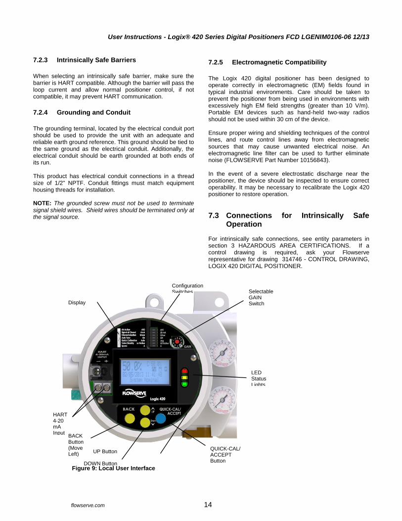
Figure 9: Local User Interface
7.2.5 Electromagnetic Compatibility
The Logix 420 digital positioner has been designed to operate correctly in electromagnetic (EM) fields found in typical industrial environments. Care should be taken to prevent the positioner from being used in environments with excessively high EM field strengths (greater than 10 V/m). Portable EM devices such as hand-held two-way radios should not be used within 30 cm of the device. Ensure proper wiring and shielding techniques of the control lines, and route control lines away from electromagnetic sources that may cause unwanted electrical noise. An electromagnetic line filter can be used to further eliminate noise (FLOWSERVE Part Number 10156843). In the event of a severe electrostatic discharge near the positioner, the device should be inspected to ensure correct operability. It may be necessary to recalibrate the Logix 420 positioner to restore operation.
7.3 Connections for Intrinsically Safe Operation
For intrinsically safe connections, see entity parameters in section 3 HAZARDOUS AREA CERTIFICATIONS. If a control drawing is required, ask your Flowserve representative for drawing 314746 - CONTROL DRAWING, LOGIX 420 DIGITAL POSITIONER.
Display
LED Status Lights
QUICK-CAL/ ACCEPT Button (Move Right)
UP Button
DOWN Button
Selectable GAIN Switch
Configuration Switches
BACK Button (Move Left)
HART 4-20 mA Input
User Instructions - Logix® 420 Series Digital Positioners FCD LGENIM0106-06 12/13
flowserve.com 15
8 STARTUP
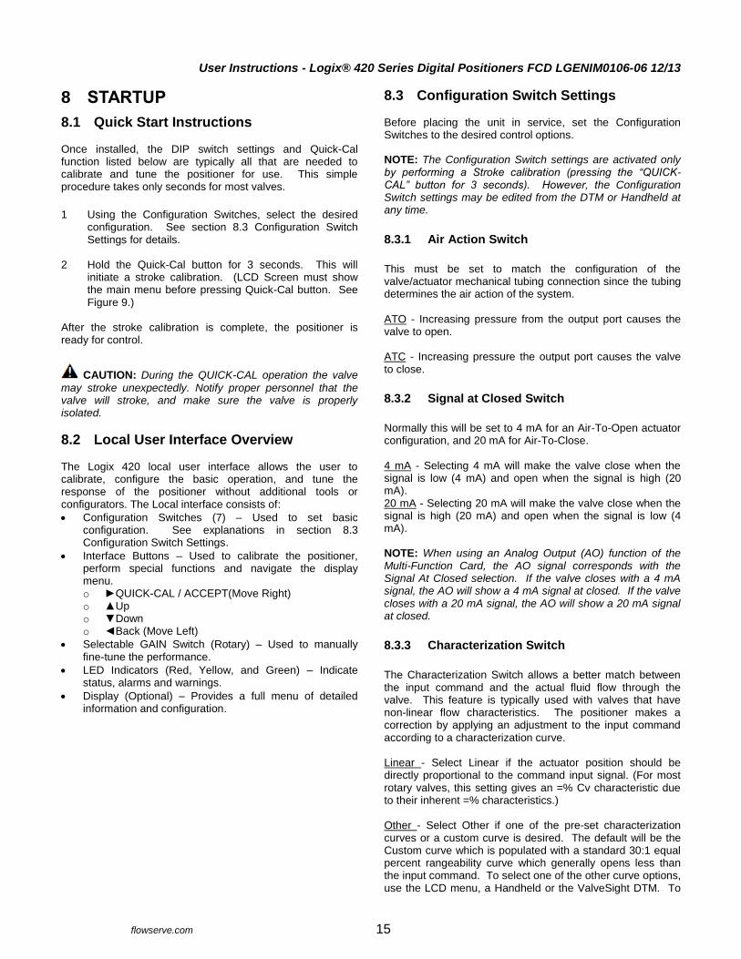
8.1 Quick Start Instructions Once installed, the DIP switch settings and Quick-Cal function listed below are typically all that are needed to calibrate and tune the positioner for use. This simple procedure takes only seconds for most valves.
1 Using the Configuration Switches, select the desired
configuration. See section 8.3 Configuration Switch Settings for details.
2 Hold the Quick-Cal button for 3 seconds. This will
initiate a stroke calibration. (LCD Screen must show the main menu before pressing Quick-Cal button. See Figure 9.)
After the stroke calibration is complete, the positioner is ready for control.
CAUTION: During the QUICK-CAL operation the valve
may stroke unexpectedly. Notify proper personnel that the valve will stroke, and make sure the valve is properly isolated.
8.2 Local User Interface Overview The Logix 420 local user interface allows the user to calibrate, configure the basic operation, and tune the response of the positioner without additional tools or configurators. The Local interface consists of: Configuration Switches (7) – Used to set basic
configuration. See explanations in section 8.3 Configuration Switch Settings.
Interface Buttons – Used to calibrate the positioner, perform special functions and navigate the display menu. o QUICK-CAL / ACCEPT(Move Right) o Up o Down o Back (Move Left)
Selectable GAIN Switch (Rotary) – Used to manually fine-tune the performance.
LED Indicators (Red, Yellow, and Green) – Indicate status, alarms and warnings.
Display (Optional) – Provides a full menu of detailed information and configuration.
8.3 Configuration Switch Settings Before placing the unit in service, set the Configuration Switches to the desired control options. NOTE: The Configuration Switch settings are activated only by performing a Stroke calibration (pressing the “QUICK-CAL” button for 3 seconds). However, the Configuration Switch settings may be edited from the DTM or Handheld at any time.
8.3.1 Air Action Switch
This must be set to match the configuration of the valve/actuator mechanical tubing connection since the tubing determines the air action of the system.
ATO - Increasing pressure from the output port causes the valve to open. ATC - Increasing pressure the output port causes the valve to close.
8.3.2 Signal at Closed Switch
Normally this will be set to 4 mA for an Air-To-Open actuator configuration, and 20 mA for Air-To-Close. 4 mA - Selecting 4 mA will make the valve close when the signal is low (4 mA) and open when the signal is high (20 mA). 20 mA - Selecting 20 mA will make the valve close when the signal is high (20 mA) and open when the signal is low (4 mA). NOTE: When using an Analog Output (AO) function of the Multi-Function Card, the AO signal corresponds with the Signal At Closed selection. If the valve closes with a 4 mA signal, the AO will show a 4 mA signal at closed. If the valve closes with a 20 mA signal, the AO will show a 20 mA signal at closed.
8.3.3 Characterization Switch
The Characterization Switch allows a better match between the input command and the actual fluid flow through the valve. This feature is typically used with valves that have non-linear flow characteristics. The positioner makes a correction by applying an adjustment to the input command according to a characterization curve. Linear - Select Linear if the actuator position should be directly proportional to the command input signal. (For most rotary valves, this setting gives an =% Cv characteristic due to their inherent =% characteristics.) Other - Select Other if one of the pre-set characterization curves or a custom curve is desired. The default will be the Custom curve which is populated with a standard 30:1 equal percent rangeability curve which generally opens less than the input command. To select one of the other curve options, use the LCD menu, a Handheld or the ValveSight DTM. To

User Instructions - Logix® 420 Series Digital Positioners FCD LGENIM0106-06 12/13
flowserve.com 16
modify the Custom curve, use the DTM. See section 10.3.6
Configuration (Characterization) for more information.
8.3.4 Auto Tune Switch
This switch controls whether the positioner will automatically tune itself during the stroke calibration (Quick-Cal), or use preset tuning parameters. On - Selecting On enables an auto tune feature that will automatically determine the positioner gain settings. The automatic tuning will be based on response parameters measured during the latest Quick-Cal. The valve response is a combination of these response parameters and the current position of the Selectable GAIN Switch. Off - Selecting Off forces the positioner to use one of the factory preset tuning sets determined by the Selectable GAIN Switch. Settings “B” through “J” are progressively higher predefined tuning sets. Selecting “A” on the Selectable Gain Switch during a Quick-Cal allows the user to use and preserve manually adjusted gains. See section 8.4 Stroke Calibration for more details. NOTE: The gain switch is live meaning that regardless of the
Auto Tune selection, the gain settings can be adjusted at any time during operation by changing the selectable GAIN switch position.
Figure 10: Selectable GAIN Switch
8.3.5 Quick Calibration Switch
This switch selects between Auto and Jog calibration modes. Auto - Use the Auto setting if the fully opened position of the valve has a mechanical stop. This is typical for most valves. In Auto mode during a stroke calibration (Quick-Cal), the positioner will fully close the valve and register the 0% position, then fully open the valve to register the 100% position. Jog - Use the Jog setting if the fully opened position of the valve has no hard stop, but needs to be set manually. In Jog mode during a stroke calibration (Quick-Cal), the positioner will fully close the valve and register the 0% position, then wait for the user to move the valve to the 100% open position using the Up and Down buttons. Press the ACCEPT/QUICK-CAL button to accept the 100% location. See section 8.4 Stroke Calibration for more details.
8.3.6 Valve Stability Switch
This switch adjusts the position control algorithm of the positioner for use with low-friction control valves or high-friction automated valves. Lo Friction - Placing the switch to Lo Friction optimizes the response for low friction, high performance control valves. This setting provides for optimum response times when used with most low friction control valves. Hi Friction - Placing the switch to the right optimizes the response for valves and actuators with high friction levels. This setting slightly slows the response and will normally stop limit cycling that can occur on high friction valves. See
section 10.3.7 Configuration (Pressure Control) for more
details.
8.3.7 Spare Switch
If special features have been purchased they may be controlled by this switch. See associated documentation for more details.
8.4 Stroke Calibration The ACCEPT/QUICK-CAL button is used to initiate an automatic stroke calibration. The stroke calibration determines the closed (0%) and open (100%) positions of the valve and gathers information about the response of the valve (such as valve stroke time) in order to determine the gains. The gains are then set automatically. After a stroke calibration, the positioner is ready to control. To perform a Quick-Cal, first ensure the Quick Calibration Switch is set to Auto or Jog (to manually adjust the stroke limits) as appropriate. Press and hold the ACCEPT/QUICK-CAL button for approximately 3 seconds. This will initiate the automatic stroke calibration. While the calibration is in progress, the LED lights will flash status codes indicating the calibration progress. See section 14.3 Status Code Descriptions for an explanation of the status code sequences. The initial calibration of extremely large or very small actuators may require several calibration attempts and will perform these automatically. The positioner adapts to the actuator performance and begins each calibration where the last attempt ended. On an initial installation it is recommended that after the first successful calibration that one more calibration be completed for optimum performance.
More Stable
More Responsive
User Instructions - Logix® 420 Series Digital Positioners FCD LGENIM0106-06 12/13
flowserve.com 17
8.4.1 Quick Calibration Switch – Jog
Set the Quick Calibration Switch to Jog if the valve/actuator assembly has no internal mechanical stop at the fully open
position. In this case, follow these instructions: 1 Press and hold the ACCEPT/QUICK-CAL button for
approximately 3 seconds. This will initiate the jog stroke calibration. The positioner will then close the valve and set the zero position. The zero position is automatically always set at the valve seat. At this point the LED‘s will flash in a sequence of G-R-R-R (green-red-red-red) which indicates that the user must use the jog keys to manually position the valve to approximately 100%. 2 Use the up and down keys to position the valve at
approximately 100% open. 3 Press the ACCEPT/QUICK-CAL button to proceed. No more user actions are required while the calibration process is completed. When the lights return to a sequence that starts with a green light the calibration is complete. The jog calibration process will only allow the user to set the span. If an elevated zero is needed a handheld or ValveSight DTM are required.
8.4.2 Tuning Options
Quick-Cal Custom Gains – This is typically the fastest way to
achieve ideal gains. Set the Auto Tune Configuration Switch to On and the Selectable GAIN Switch to “E”. Then perform a Quick-Cal. During the Quick-Cal, custom tuning parameters will be determined based on measured response parameters. The gains can then be fine-tuned by adjusting the Selectable GAIN Switch. Selecting “D” “C” or “B” will progressively provide a more stable response. Selecting “F” through “J” will progressively provide a more active response. In most cases selecting “E” will give the best results. This is the default setting for all actuator sizes. Raising or lowering the Selectable GAIN Switch setting is a function of the positioner/valve response to the control signal, and is not actuator size dependent. Standard Preset Gains - If standard, preset gains are desired, set the Auto Tune Configuration Switch to Off. After performing a Quick-Cal, use the Selectable GAIN switch to the desired level (“B” – “J”). The standard, preset gain settings are not affected by Quick-Cal. It may be necessary to set the gain switch before the Quick Cal. Very fast stroking valves may need to be at lower gains and very slow stroking valves may need to be at higher gains. It may be necessary to set the gain switch BEFORE the Quick Cal. Very fast stroking valves may need to be at lower gains and very slow stroking valves may need to be at higher gains.
Custom Manual Gains - To set gains manually, set the selectable GAIN switch to “A”. Changing the switch from “B” to “A” will write the standard “B” settings into the “A” parameters, allowing a starting point for modification. Similarly, changing the switch from “J” to “A” will write the standard “J” settings into the “A” parameters. Custom tuning values can then be entered using the Display Menu, a Handheld or ValveSight DTM. With the Selectable GAIN Switch set to “A”, the tuning will not be modified during a Quick-Cal.
8.4.3 Aborting a Quick-Cal
The Quick-Cal can be aborted at any time by briefly pressing the ACCEPT/QUICK-CAL button again. In this case, the previous settings will be retained.
8.4.4 On Line Stroke Calibration Adjustments
At times an adjustment to the calibration is desired, but the process cannot be interrupted. The stroke calibration can be adjusted with minimal valve movement. Contact your local Field Service Technician for more information.

User Instructions - Logix® 420 Series Digital Positioners FCD LGENIM0106-06 12/13
flowserve.com 18
9 POSITIONER FUNCTIONS (No Display Required)
The following features can be performed using the local interface. No display is required for these features. Additional features are offered with the use of a display, Handheld or DTM. NOTE: In order to prevent unintentional adjustments of the configuration, tuning, or control of the valve, the Tamper Lock feature may be used. This is set in the DTM and disables the buttons and menus except for the ability to view the status of the positioner. When locked, the positioner may be temporarily unlocked by entering a PIN. (An LCD is required to enter the PIN.) Or, the positioner can be unlocked from the DTM.
9.1 Live Manual Tuning (Adjusting the Gain)
Use the Selectable GAIN Switch to adjust the gain at any time during operation. This adjustment takes effect immediately. For faster response select settings above “E” (F-J). For more stable response, select settings below “E” (B-D). See Figure 10: Selectable GAIN Switch on page 16.
9.2 Local Control Of Valve Position To manually adjust the position of the valve regardless of the input command (analog or digital), press and hold the Up, Down and BACK buttons for about 3 seconds. The Up, down buttons can then be used to position the valve. While in this mode the LED‘s will flash a GRRY (green-red-red-yellow) sequence. To exit the local control mode and return to normal operation, briefly press the ACCEPT/QUICK-CAL button.
CAUTION: When operating using local control of the
valve, the valve will not respond to external commands. Notify proper personnel that the valve will not respond to remote command changes, and make sure the valve is properly isolated.
9.3 Command Source Reset Performing a command source reset will reset the command source to analog if it has been inadvertently left in digital mode. This is done by holding down both the Up and Down buttons, then briefly pressing the ACCCEPT/QUICK-CAL button.
9.4 Factory Reset To perform a factory reset, hold ACCEPT/QUICK-CAL button while applying power. All of the internal variables including calibration will be reset to factory defaults. The positioner must be re-calibrated after a factory reset. Tag names and other user configured limits, alarm settings, and valve information will also be lost and need to be restored. A factory reset will always reset the command source to analog 4-20 mA.
CAUTION: Performing a factory reset may result in the
inability to operate the valve until reconfigured properly. Notify proper personnel that the valve may stroke, and make sure the valve is properly isolated.
User Instructions - Logix® 420 Series Digital Positioners FCD LGENIM0106-06 12/13
flowserve.com 19
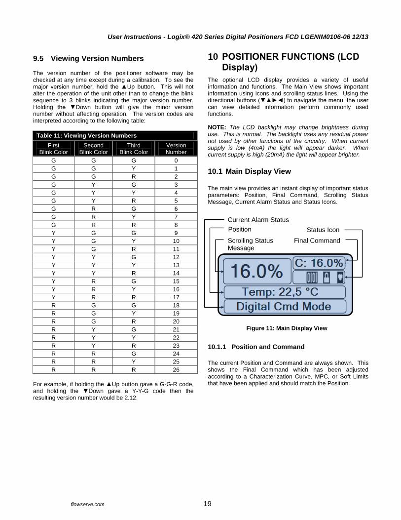
9.5 Viewing Version Numbers The version number of the positioner software may be checked at any time except during a calibration. To see the major version number, hold the Up button. This will not alter the operation of the unit other than to change the blink sequence to 3 blinks indicating the major version number. Holding the Down button will give the minor version number without affecting operation. The version codes are interpreted according to the following table:
Table 11: Viewing Version Numbers
First Blink Color
Second Blink Color
Third Blink Color
Version Number
G G G 0
G G Y 1
G G R 2
G Y G 3
G Y Y 4
G Y R 5
G R G 6
G R Y 7
G R R 8
Y G G 9
Y G Y 10
Y G R 11
Y Y G 12
Y Y Y 13
Y Y R 14
Y R G 15
Y R Y 16
Y R R 17
R G G 18
R G Y 19
R G R 20
R Y G 21
R Y Y 22
R Y R 23
R R G 24
R R Y 25
R R R 26
For example, if holding the Up button gave a G-G-R code, and holding the Down gave a Y-Y-G code then the resulting version number would be 2.12.
10 POSITIONER FUNCTIONS (LCD Display)
The optional LCD display provides a variety of useful information and functions. The Main View shows important information using icons and scrolling status lines. Using the directional buttons () to navigate the menu, the user can view detailed information perform commonly used functions. NOTE: The LCD backlight may change brightness during use. This is normal. The backlight uses any residual power not used by other functions of the circuitry. When current supply is low (4mA) the light will appear darker. When current supply is high (20mA) the light will appear brighter.
10.1 Main Display View
The main view provides an instant display of important status parameters: Position, Final Command, Scrolling Status Message, Current Alarm Status and Status Icons.
10.1.1 Position and Command
The current Position and Command are always shown. This shows the Final Command which has been adjusted according to a Characterization Curve, MPC, or Soft Limits that have been applied and should match the Position.
Figure 11: Main Display View
Final Command
Status Icon Position
Scrolling Status Message
Current Alarm Status
User Instructions - Logix® 420 Series Digital Positioners FCD LGENIM0106-06 12/13
flowserve.com 20
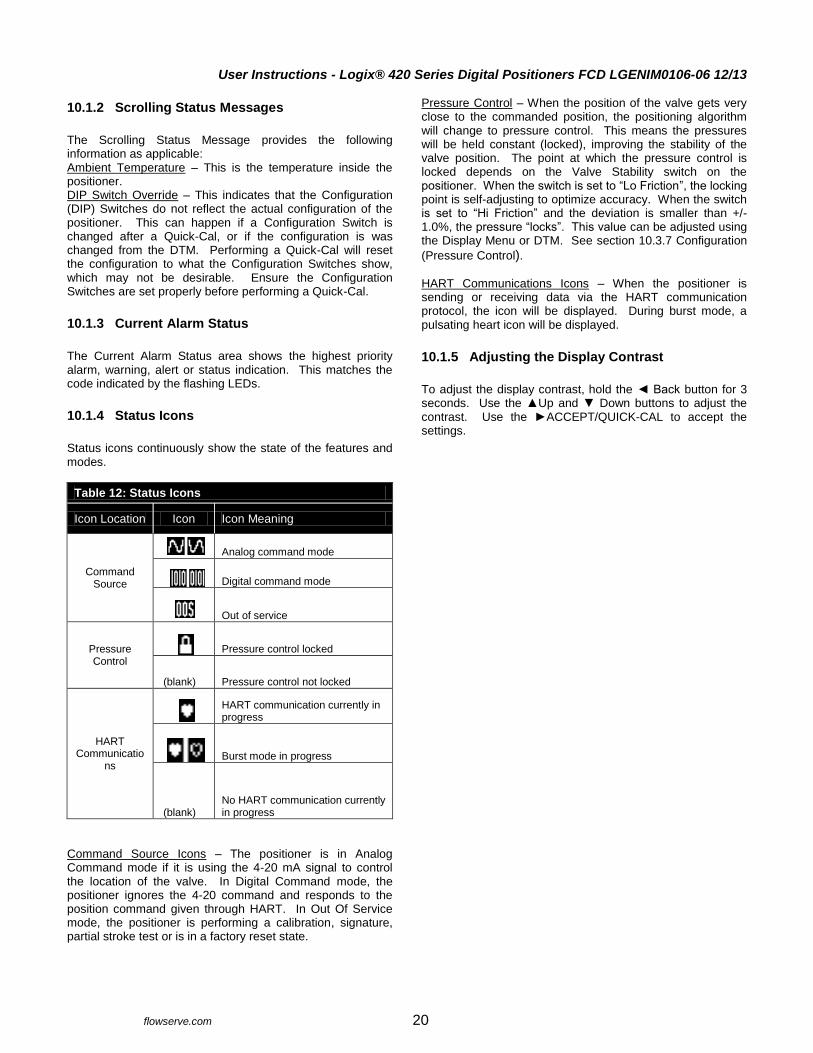
10.1.2 Scrolling Status Messages
The Scrolling Status Message provides the following information as applicable: Ambient Temperature – This is the temperature inside the positioner. DIP Switch Override – This indicates that the Configuration (DIP) Switches do not reflect the actual configuration of the positioner. This can happen if a Configuration Switch is changed after a Quick-Cal, or if the configuration is was changed from the DTM. Performing a Quick-Cal will reset the configuration to what the Configuration Switches show, which may not be desirable. Ensure the Configuration Switches are set properly before performing a Quick-Cal.
10.1.3 Current Alarm Status
The Current Alarm Status area shows the highest priority alarm, warning, alert or status indication. This matches the code indicated by the flashing LEDs.
10.1.4 Status Icons
Status icons continuously show the state of the features and modes.
Table 12: Status Icons
Icon Location Icon Icon Meaning
Command Source
Analog command mode
Digital command mode
Out of service
Pressure Control
Pressure control locked
(blank) Pressure control not locked
HART Communicatio
ns
HART communication currently in progress
Burst mode in progress
(blank) No HART communication currently in progress
Command Source Icons – The positioner is in Analog Command mode if it is using the 4-20 mA signal to control the location of the valve. In Digital Command mode, the positioner ignores the 4-20 command and responds to the position command given through HART. In Out Of Service mode, the positioner is performing a calibration, signature, partial stroke test or is in a factory reset state.
Pressure Control – When the position of the valve gets very close to the commanded position, the positioning algorithm will change to pressure control. This means the pressures will be held constant (locked), improving the stability of the valve position. The point at which the pressure control is locked depends on the Valve Stability switch on the positioner. When the switch is set to “Lo Friction”, the locking point is self-adjusting to optimize accuracy. When the switch is set to “Hi Friction” and the deviation is smaller than +/- 1.0%, the pressure “locks”. This value can be adjusted using the Display Menu or DTM. See section 10.3.7 Configuration
(Pressure Control). HART Communications Icons – When the positioner is sending or receiving data via the HART communication protocol, the icon will be displayed. During burst mode, a pulsating heart icon will be displayed.
10.1.5 Adjusting the Display Contrast
To adjust the display contrast, hold the Back button for 3 seconds. Use the Up and Down buttons to adjust the contrast. Use the ACCEPT/QUICK-CAL to accept the settings.
User Instructions - Logix® 420 Series Digital Positioners FCD LGENIM0106-06 12/13
flowserve.com 21
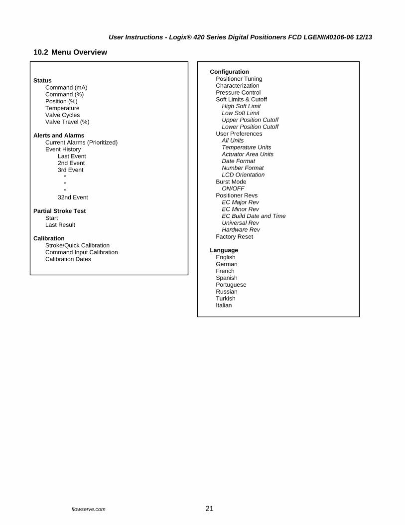
10.2 Menu Overview Status
Command (mA) Command (%) Position (%) Temperature Valve Cycles Valve Travel (%)
Alerts and Alarms
Current Alarms (Prioritized) Event History
Last Event 2nd Event 3rd Event
* * *
32nd Event Partial Stroke Test
Start Last Result
Calibration
Stroke/Quick Calibration Command Input Calibration Calibration Dates
Configuration
Positioner Tuning Characterization Pressure Control Soft Limits & Cutoff
High Soft Limit Low Soft Limit Upper Position Cutoff Lower Position Cutoff
User Preferences All Units Temperature Units Actuator Area Units Date Format Number Format LCD Orientation
Burst Mode ON/OFF
Positioner Revs EC Major Rev EC Minor Rev EC Build Date and Time Universal Rev Hardware Rev
Factory Reset Language
English German French Spanish Portuguese Russian Turkish Italian

User Instructions - Logix® 420 Series Digital Positioners FCD LGENIM0106-06 12/13
flowserve.com 22
10.3 Menu Features
10.3.1 Status
The Status menu is used to view information about the configuration and operation of the system. Command displays the final command in mA. Command displays the final command in %. Position displays the valve position in %. Temperature displays the temperature inside the positioner. Valve Cycles are counted each time the positioner changes direction. The movement must be beyond a dead-band window. This window is set to 0.5% as a default, but can be changed using the DTM. Valve Travel is counted in small increments every time the valve moves beyond the dead-band window. The travel is displayed in % of full stroke.
10.3.2 Alerts and Alarms
The Alerts and Alarms menu shows current and past alarms, warnings, alerts, and calibrations. Current Alarms displays all events that are actively sounding. Event History displays past 32 events including alarms, warnings, alerts, and calibrations. The event that occurred most recently is displayed first (event 32) with later events recorded below.
10.3.3 Partial Stroke Test
The Partial Stroke Test (PST) menu provides the user the ability to start a PST and see the results of the latest PST.
CAUTION: Performing a Partial Stroke Test will result in
valve movement and the inability to operate the valve until the test is complete. Notify proper personnel that the valve may stroke, and make sure the valve is properly isolated if required by plant procedures.
Start allows the user to initialize the (PST). Last Result shows “Pass” or “Fail” from the last PST attempt.
10.3.4 Calibration
The Calibration menu allows the user to calibrate the positioner’s sensors. The positioner can accurately control with only a Quick-Cal. Typically this is all that is needed. A friction calibration is recommended if the positioner has been upgraded to Pro diagnostics. See section 8 STARTUP for more details.
CAUTION: Performing a calibration may result in valve
movement and the inability to operate the valve until the calibration is complete. Notify proper personnel that the valve may stroke, and make sure the valve is properly isolated before proceeding.
Stroke/Quick Calibration starts an automatic calibration of the position feedback sensor. The stroke calibration determines the closed (0%) and open (100%) positions of the valve and gathers information about the response of the valve (such as valve stroke time) in order to determine the gains. The gains are then set automatically. After a stroke calibration, the positioner is ready to control. See section 8.4 Stroke Calibration for more information. Command Input Calibration is used to adjust the input range. Set the lowest current (Set 0%) and the highest current (Set 100%) that will be used. The default input range is 4 to 20 mA. The “Set 0%” value must be lower than the “Set 100% value.
Status Command (mA) Command (%) Position (%) Temperature Valve Cycles Valve Travel (%)
Alerts and Alarms Current Alarms (Prioritized) Event History
Last Event 2nd Event 3rd Event
* * *
32nd Event
Partial Stroke Test Start
Last Result
Calibration Stroke/Quick Calibration Command Input Calibration
Calibration Dates
User Instructions - Logix® 420 Series Digital Positioners FCD LGENIM0106-06 12/13
flowserve.com 23
Split Range Example:
A split range is easily configured. For example, a 4 to 12 mA signal can be set to correspond to a 0 to 100% stroke. When the display shows “Set 0%”, set the command input current to 4 mA. (The display will show a low Analog to Digital Count (ADC) that corresponds to 4 mA.) Then press the ACCEPT/QUICK-CAL button to set the value. Press the Down button to move to “Set 100%”. Set the command input current to 12 mA. (The display will show a high ADC to correspond to 12 mA.) Again press the ACCEPT/QUICK-CAL button to set the value. Select the Back Button to exit. Signal At Closed = 20mA Example:
If the desired signal at closed is 20 mA, first set the Signal at Closed DIP switch to 20 mA. Then perform a stroke calibration by pressing the ACCEPT/QUICK-CAL button for more than 3 seconds. This registers the DIP switch settings. Then, in the Command Input Calibration menu, when the display shows “Set 0%” it is expecting the lowest current value. Set the input current to 4 mA. For “Set 100%”, it is looking for the highest current value. Set the input current to 20 mA. After accepting theses values, the positioner will interpret the 20 mA input as 0% valve position and the 4 mA input as 100%. Calibration Dates lists the most recent date of each calibration. The date is available only if the calibration was performed using the DTM.
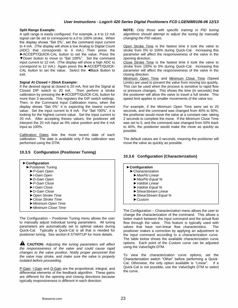
10.3.5 Configuration (Positioner Tuning)
The Configuration – Positioner Tuning menu allows the user to manually adjust individual tuning parameters. All tuning parameters are automatically set to optimal values during Quick-Cal. Typically a Quick-Cal is all that is needed for positioner tuning. See section 8 STARTUP for more details.
CAUTION: Adjusting the tuning parameters will affect
the responsiveness of the valve and could cause rapid changes to the valve position. Notify proper personnel that the valve may stroke, and make sure the valve is properly isolated before proceeding. P-Gain, I-Gain and D-Gain are the proportional, integral, and differential elements of the feedback algorithm. These gains are different for the opening and closing directions because typically responsiveness is different in each direction.
NOTE: Only those with specific training in PID tuning algorithms should attempt to adjust the tuning by manually changing the PID values. Open Stroke Time is the fastest time it took the valve to stroke from 0% to 100% during Quick-Cal. Increasing this parameter will affect the responsiveness of the valve in the opening direction. Close Stroke Time is the fastest time it took the valve to stroke from 100% to 0% during Quick-Cal. Increasing this parameter will affect the responsiveness of the valve in the closing direction. Minimum Open Time and Minimum Close Time (Speed Limits) are used to prevent the valve from moving too quickly. This can be used when the process is sensitive to rapid flow or pressure changes. This shows the time (in seconds) that the positioner will allow the valve to travel a full stroke. This speed limit applies to smaller movements of the valve too. For example, if the Minimum Open Time were set to 20 seconds, and the command was changed from 40% to 50%, the positioner would move the valve at a constant rate, taking 2 seconds to complete the move. If the Minimum Close Time was set to 0, and the command was changed from 50% back to 40%, the positioner would make the move as quickly as possible. The default values are 0 seconds, meaning the positioner will move the valve as quickly as possible.
10.3.6 Configuration (Characterization)
The Configuration – Characterization menu allows the user to change the characterization of the command. This allows a better match between the input command and the actual fluid flow through the valve. This feature is typically used with valves that have non-linear flow characteristics. The positioner makes a correction by applying an adjustment to the input command according to a characterization curve. The table below shows the available characterization curve options. Each point of the Custom curve can be adjusted using the ValveSight DTM. To view the characterization curve options, set the Characterization switch “Other” before performing a Quick-Cal. Otherwise, the only option available is “Linear”. If a Quick-Cal is not possible, use the ValveSight DTM to select the curve.
Configuration Positioner Tuning
P-Gain Open I-Gain Open D-Gain Open P-Gain Close I-Gain Close D-Gain Close Open Stroke Time Close Stroke Time Minimum Open Time
Minimum Close Time
Configuration Characterization
MaxFlo Linear MaxFlo Equal % Valdisk Linear Valdisk Equal % ShearStream Linear ShearStream Equal %
Custom
User Instructions - Logix® 420 Series Digital Positioners FCD LGENIM0106-06 12/13
flowserve.com 24
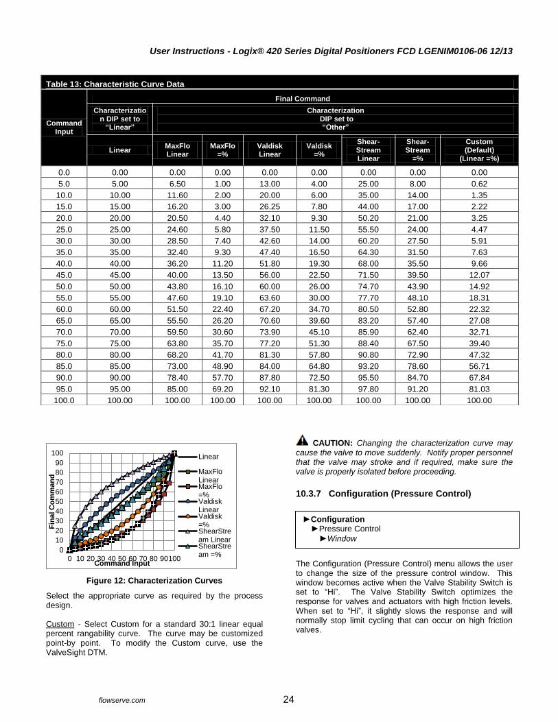
Figure 12: Characterization Curves
Select the appropriate curve as required by the process design. Custom - Select Custom for a standard 30:1 linear equal percent rangability curve. The curve may be customized point-by point. To modify the Custom curve, use the ValveSight DTM.
CAUTION: Changing the characterization curve may
cause the valve to move suddenly. Notify proper personnel that the valve may stroke and if required, make sure the valve is properly isolated before proceeding.
10.3.7 Configuration (Pressure Control)
The Configuration (Pressure Control) menu allows the user to change the size of the pressure control window. This window becomes active when the Valve Stability Switch is set to “Hi”. The Valve Stability Switch optimizes the response for valves and actuators with high friction levels. When set to “Hi”, it slightly slows the response and will normally stop limit cycling that can occur on high friction valves.
0
10
20
30
40
50
60
70
80
90
100
0 10 20 30 40 50 60 70 80 90100
Fin
al C
om
man
d
Command Input
Linear
MaxFloLinearMaxFlo=%ValdiskLinearValdisk=%ShearStream LinearShearStream =%
Table 13: Characteristic Curve Data
Command Input
Final Command
Characterization DIP set to
“Linear”
Characterization DIP set to
“Other”
Linear MaxFlo Linear
MaxFlo =%
Valdisk Linear
Valdisk =%
Shear-Stream Linear
Shear-Stream
=%
Custom (Default)
(Linear =%)
0.0 0.00 0.00 0.00 0.00 0.00 0.00 0.00 0.00
5.0 5.00 6.50 1.00 13.00 4.00 25.00 8.00 0.62
10.0 10.00 11.60 2.00 20.00 6.00 35.00 14.00 1.35
15.0 15.00 16.20 3.00 26.25 7.80 44.00 17.00 2.22
20.0 20.00 20.50 4.40 32.10 9.30 50.20 21.00 3.25
25.0 25.00 24.60 5.80 37.50 11.50 55.50 24.00 4.47
30.0 30.00 28.50 7.40 42.60 14.00 60.20 27.50 5.91
35.0 35.00 32.40 9.30 47.40 16.50 64.30 31.50 7.63
40.0 40.00 36.20 11.20 51.80 19.30 68.00 35.50 9.66
45.0 45.00 40.00 13.50 56.00 22.50 71.50 39.50 12.07
50.0 50.00 43.80 16.10 60.00 26.00 74.70 43.90 14.92
55.0 55.00 47.60 19.10 63.60 30.00 77.70 48.10 18.31
60.0 60.00 51.50 22.40 67.20 34.70 80.50 52.80 22.32
65.0 65.00 55.50 26.20 70.60 39.60 83.20 57.40 27.08
70.0 70.00 59.50 30.60 73.90 45.10 85.90 62.40 32.71
75.0 75.00 63.80 35.70 77.20 51.30 88.40 67.50 39.40
80.0 80.00 68.20 41.70 81.30 57.80 90.80 72.90 47.32
85.0 85.00 73.00 48.90 84.00 64.80 93.20 78.60 56.71
90.0 90.00 78.40 57.70 87.80 72.50 95.50 84.70 67.84
95.0 95.00 85.00 69.20 92.10 81.30 97.80 91.20 81.03
100.0 100.00 100.00 100.00 100.00 100.00 100.00 100.00 100.00
Configuration Pressure Control
Window
User Instructions - Logix® 420 Series Digital Positioners FCD LGENIM0106-06 12/13
flowserve.com 25
Window - When the position of the valve gets within the pressure control window, the positioning algorithm will change to pressure control. This means the pressures will be held constant (locked), improving the stability of the valve position. NOTE: The pressure control feature of the Logix 420 functions without the use of pressure sensors. In the DTM, this feature is configured on the Valve Stability page.
10.3.8 Configuration (Soft Limits and Shutoff)
Soft Limits allows the user to limit the movement of the valve. Shutoff allows the user to tightly shut the valve with all available force. High Soft Limit and Low Soft Limit - This feature is used to simulate physical blocks on the valve that restrict movement past a set point. Once the Soft Limit is set, the positioner will not attempt to move the valve position (final command) beyond the set point, regardless of the analog or digital command input signal.
CAUTION: Changing the Soft Limits may limit the
movement of the valve. The valve may not shut or open fully.
NOTE: Removing power to below 3.6 mA will still cause the valve to move to the de-energized state regardless of the Soft Limits.
Upper Position Shutoff and Lower Position Shutoff - This feature, (also called Minimum Position Cutoff or MPC) is used to tightly close or open the valve. It is used when a tight seal is needed or when debris or friction may otherwise interfere with complete closure. When the valve is commanded past the Shutoff points, the pilot relay will direct full supply pressure to the appropriate port, applying all available force to close (or open) the valve. The Shutoff points apply to the Final Command.
CAUTION: Changing the Shutoff limits may cause the
valve to fully open or fully close after the command passes a set limit.
Though Shutoff and Soft Limit features should not be used together, if both are set, the greater of the two settings will take precedence at the closed end; and the lesser of the two settings will take precedence at the open end.
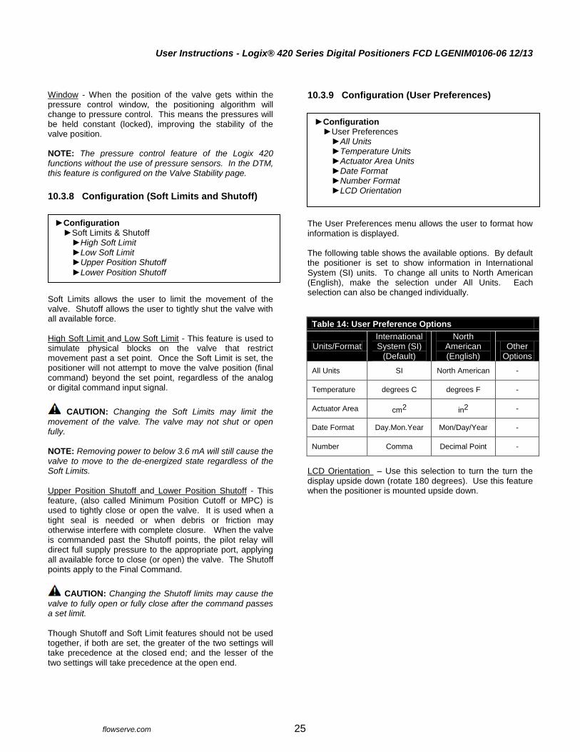
10.3.9 Configuration (User Preferences)
The User Preferences menu allows the user to format how information is displayed. The following table shows the available options. By default the positioner is set to show information in International System (SI) units. To change all units to North American (English), make the selection under All Units. Each selection can also be changed individually.
Table 14: User Preference Options
Units/Format International System (SI)
(Default)
North American (English)
Other Options
All Units SI North American -
Temperature degrees C degrees F -
Actuator Area cm2 in2 -
Date Format Day.Mon.Year Mon/Day/Year -
Number Comma Decimal Point -
LCD Orientation – Use this selection to turn the turn the display upside down (rotate 180 degrees). Use this feature when the positioner is mounted upside down.
Configuration Soft Limits & Shutoff
High Soft Limit Low Soft Limit Upper Position Shutoff
Lower Position Shutoff
Configuration User Preferences
All Units Temperature Units Actuator Area Units Date Format Number Format LCD Orientation
User Instructions - Logix® 420 Series Digital Positioners FCD LGENIM0106-06 12/13
flowserve.com 26
10.3.10 Configuration (Burst Mode)
Burst Mode continuously transmits HART information. On/Off – Use this feature to turn burst mode on and off.
10.3.11 Configuration (Positioner Revs)
Positioner revisions are shown in this menu. SW Rev –The revision of the embedded software. Bld Date –The date of the embedded software build. Bld Time –The time of day of the embedded software build. HW Rev –The revision of the main board. CPU Rev – The revision of the CPU. HART Ver –The revision of the HART protocol (5, 6, or 7).
10.3.12 Configuration (Factory Reset)
At times, it may be convenient to reset all of the variables to a default state. In this case, perform a Factory Reset. Factory Reset – Use this feature to reset all variables to their factory default state. All of the internal variables including calibration will be reset to factory defaults. The positioner must be re-calibrated after a factory reset. Tag names and other user configured limits, alarm settings, and valve information will also be lost and will need to be restored. A factory reset will always reset the command source to analog 4-20 mA.
CAUTION: Performing a factory reset may result in the
inability to operate the valve until reconfigured properly. Notify proper personnel that the valve may stroke, and make sure the valve is properly isolated.
10.3.13 Language
The display menu is available in several languages.
NOTE: To navigate directly to the language menu, select the following sequence of buttons: Up , Up, QUICK-CAL/ACCEPT.
Configuration Burst Mode
On/Off
Configuration Positioner Revs
SW Rev Bld Date Bld Time HW Rev CPU Rev HART Ver
Configuration
Factory Reset
Language English German French Spanish Portuguese Russian Turkish Italian
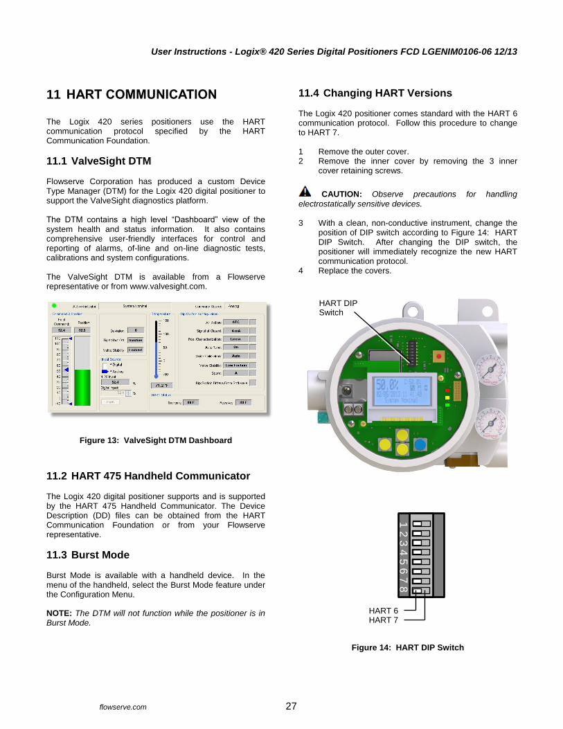
User Instructions - Logix® 420 Series Digital Positioners FCD LGENIM0106-06 12/13
flowserve.com 27
11 HART COMMUNICATION
The Logix 420 series positioners use the HART communication protocol specified by the HART Communication Foundation.
11.1 ValveSight DTM Flowserve Corporation has produced a custom Device Type Manager (DTM) for the Logix 420 digital positioner to support the ValveSight diagnostics platform. The DTM contains a high level “Dashboard” view of the system health and status information. It also contains comprehensive user-friendly interfaces for control and reporting of alarms, of-line and on-line diagnostic tests, calibrations and system configurations. The ValveSight DTM is available from a Flowserve representative or from www.valvesight.com.
Figure 13: ValveSight DTM Dashboard
11.2 HART 475 Handheld Communicator The Logix 420 digital positioner supports and is supported by the HART 475 Handheld Communicator. The Device Description (DD) files can be obtained from the HART Communication Foundation or from your Flowserve representative.
11.3 Burst Mode Burst Mode is available with a handheld device. In the menu of the handheld, select the Burst Mode feature under the Configuration Menu. NOTE: The DTM will not function while the positioner is in Burst Mode.
11.4 Changing HART Versions The Logix 420 positioner comes standard with the HART 6 communication protocol. Follow this procedure to change to HART 7. 1 Remove the outer cover. 2 Remove the inner cover by removing the 3 inner
cover retaining screws.
CAUTION: Observe precautions for handling
electrostatically sensitive devices. 3 With a clean, non-conductive instrument, change the
position of DIP switch according to Figure 14: HART DIP Switch. After changing the DIP switch, the positioner will immediately recognize the new HART communication protocol.
4 Replace the covers.
Figure 14: HART DIP Switch
HART DIP Switch
HART 6 HART 7
1 2
3 4
5 6
7 8
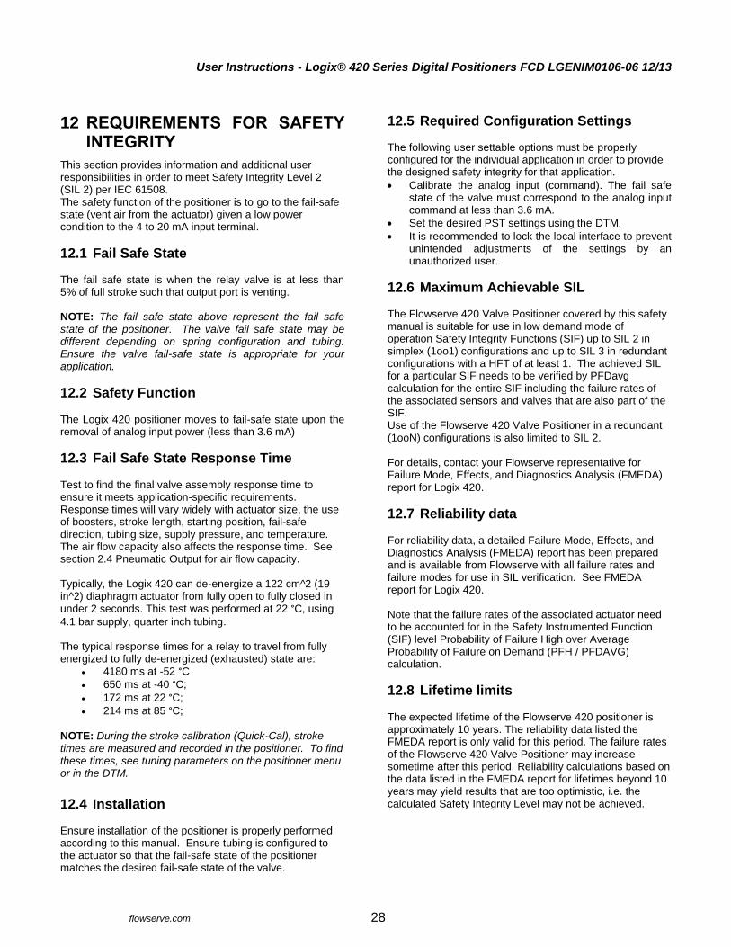
User Instructions - Logix® 420 Series Digital Positioners FCD LGENIM0106-06 12/13
flowserve.com 28
12 REQUIREMENTS FOR SAFETY INTEGRITY
This section provides information and additional user responsibilities in order to meet Safety Integrity Level 2 (SIL 2) per IEC 61508. The safety function of the positioner is to go to the fail-safe state (vent air from the actuator) given a low power condition to the 4 to 20 mA input terminal.
12.1 Fail Safe State The fail safe state is when the relay valve is at less than 5% of full stroke such that output port is venting. NOTE: The fail safe state above represent the fail safe state of the positioner. The valve fail safe state may be different depending on spring configuration and tubing. Ensure the valve fail-safe state is appropriate for your application.
12.2 Safety Function The Logix 420 positioner moves to fail-safe state upon the removal of analog input power (less than 3.6 mA)
12.3 Fail Safe State Response Time Test to find the final valve assembly response time to ensure it meets application-specific requirements. Response times will vary widely with actuator size, the use of boosters, stroke length, starting position, fail-safe direction, tubing size, supply pressure, and temperature. The air flow capacity also affects the response time. See section 2.4 Pneumatic Output for air flow capacity. Typically, the Logix 420 can de-energize a 122 cm^2 (19 in^2) diaphragm actuator from fully open to fully closed in under 2 seconds. This test was performed at 22 °C, using
4.1 bar supply, quarter inch tubing. The typical response times for a relay to travel from fully energized to fully de-energized (exhausted) state are:
4180 ms at -52 °C
650 ms at -40 °C;
172 ms at 22 °C;
214 ms at 85 °C;
NOTE: During the stroke calibration (Quick-Cal), stroke times are measured and recorded in the positioner. To find these times, see tuning parameters on the positioner menu or in the DTM.
12.4 Installation Ensure installation of the positioner is properly performed according to this manual. Ensure tubing is configured to the actuator so that the fail-safe state of the positioner matches the desired fail-safe state of the valve.
12.5 Required Configuration Settings The following user settable options must be properly configured for the individual application in order to provide the designed safety integrity for that application.
Calibrate the analog input (command). The fail safe state of the valve must correspond to the analog input command at less than 3.6 mA.
Set the desired PST settings using the DTM.
It is recommended to lock the local interface to prevent unintended adjustments of the settings by an unauthorized user.
12.6 Maximum Achievable SIL The Flowserve 420 Valve Positioner covered by this safety manual is suitable for use in low demand mode of operation Safety Integrity Functions (SIF) up to SIL 2 in simplex (1oo1) configurations and up to SIL 3 in redundant configurations with a HFT of at least 1. The achieved SIL for a particular SIF needs to be verified by PFDavg calculation for the entire SIF including the failure rates of the associated sensors and valves that are also part of the SIF. Use of the Flowserve 420 Valve Positioner in a redundant (1ooN) configurations is also limited to SIL 2. For details, contact your Flowserve representative for Failure Mode, Effects, and Diagnostics Analysis (FMEDA) report for Logix 420.
12.7 Reliability data For reliability data, a detailed Failure Mode, Effects, and Diagnostics Analysis (FMEDA) report has been prepared and is available from Flowserve with all failure rates and failure modes for use in SIL verification. See FMEDA report for Logix 420. Note that the failure rates of the associated actuator need to be accounted for in the Safety Instrumented Function (SIF) level Probability of Failure High over Average Probability of Failure on Demand (PFH / PFDAVG) calculation.
12.8 Lifetime limits The expected lifetime of the Flowserve 420 positioner is approximately 10 years. The reliability data listed the FMEDA report is only valid for this period. The failure rates of the Flowserve 420 Valve Positioner may increase sometime after this period. Reliability calculations based on the data listed in the FMEDA report for lifetimes beyond 10 years may yield results that are too optimistic, i.e. the calculated Safety Integrity Level may not be achieved.
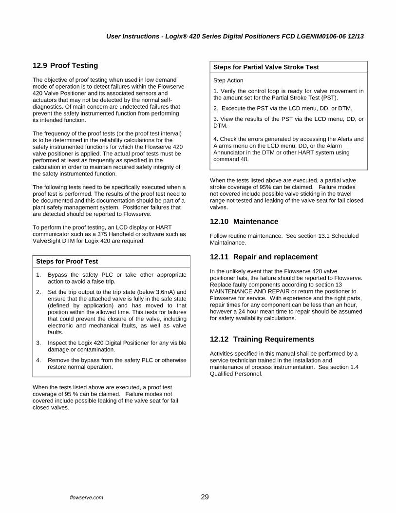
User Instructions - Logix® 420 Series Digital Positioners FCD LGENIM0106-06 12/13
flowserve.com 29
12.9 Proof Testing The objective of proof testing when used in low demand mode of operation is to detect failures within the Flowserve 420 Valve Positioner and its associated sensors and actuators that may not be detected by the normal self-diagnostics. Of main concern are undetected failures that prevent the safety instrumented function from performing its intended function. The frequency of the proof tests (or the proof test interval) is to be determined in the reliability calculations for the safety instrumented functions for which the Flowserve 420 valve positioner is applied. The actual proof tests must be performed at least as frequently as specified in the calculation in order to maintain required safety integrity of the safety instrumented function. The following tests need to be specifically executed when a proof test is performed. The results of the proof test need to be documented and this documentation should be part of a plant safety management system. Positioner failures that are detected should be reported to Flowserve. To perform the proof testing, an LCD display or HART communicator such as a 375 Handheld or software such as ValveSight DTM for Logix 420 are required.
Steps for Proof Test
1. Bypass the safety PLC or take other appropriate action to avoid a false trip.
2. Set the trip output to the trip state (below 3.6mA) and ensure that the attached valve is fully in the safe state (defined by application) and has moved to that position within the allowed time. This tests for failures that could prevent the closure of the valve, including electronic and mechanical faults, as well as valve faults.
3. Inspect the Logix 420 Digital Positioner for any visible damage or contamination.
4. Remove the bypass from the safety PLC or otherwise restore normal operation.
When the tests listed above are executed, a proof test coverage of 95 % can be claimed. Failure modes not covered include possible leaking of the valve seat for fail closed valves.
Steps for Partial Valve Stroke Test
Step Action
1. Verify the control loop is ready for valve movement in the amount set for the Partial Stroke Test (PST).
2. Excecute the PST via the LCD menu, DD, or DTM.
3. View the results of the PST via the LCD menu, DD, or DTM. 4. Check the errors generated by accessing the Alerts and Alarms menu on the LCD menu, DD, or the Alarm Annunciator in the DTM or other HART system using command 48.
When the tests listed above are executed, a partial valve stroke coverage of 95% can be claimed. Failure modes not covered include possible valve sticking in the travel range not tested and leaking of the valve seat for fail closed valves.
12.10 Maintenance Follow routine maintenance. See section 13.1 Scheduled Maintainance.
12.11 Repair and replacement In the unlikely event that the Flowserve 420 valve positioner fails, the failure should be reported to Flowserve. Replace faulty components according to section 13 MAINTENANCE AND REPAIR or return the positioner to Flowserve for service. With experience and the right parts, repair times for any component can be less than an hour, however a 24 hour mean time to repair should be assumed for safety availability calculations.
12.12 Training Requirements Activities specified in this manual shall be performed by a service technician trained in the installation and maintenance of process instrumentation. See section 1.4 Qualified Personnel.

User Instructions - Logix® 420 Series Digital Positioners FCD LGENIM0106-06 12/13
flowserve.com 30
13 MAINTENANCE AND REPAIR
The kits listed in section 16.2 Spare Parts Kits can be
replaced by a technician trained in positioner function and handling of static sensitive devices.
CAUTION: Depressurize the positioner before
servicing.
CAUTION: Use eye protection.
CAUTION: When touching the circuit boards, observe
precautions for handling electrostatically sensitive devices.
13.1 Scheduled Maintainance The supply gas filter(s) should be scheduled for regular maintenance as required to maintain supply gas quality. If contamination is found in the filter, the inside of the positioner should be visually inspected for contamination. If contamination is found in the positioner, the positioner should be replaced.
13.2 Required Tools and Equipment The Logix 420 digital positioner has modular components that can be replaced using these tools:
Figure 15: Tools for Positioner Maintenance
13.3 Replacing a Main Board
Removal 1 Make sure the valve is bypassed or in a safe
condition. 2 Remove the outer cover. 3 Disconnect the power to the positioner. 4 Remove the inner cover by removing the 3 retaining
screws. 5 Gently lift the main board rotating the bottom up while
keeping the top in place.
6 Disconnect the hall sensor cable, the piezo cable and the feedback cable. Use a small flat screwdriver to press in the locking features and carefully separate the connector from the main board. Be careful not to pull the cable, as this may cause damage to the cable.
Installation 1 Place the main board on the positioner base with the
4-20 mA input on the same side as the electronic access ports.
2 Lift the main board rotating the bottom (configuration switches) upwards while keeping the top in place.
3 Connect the pressure sensor board cable, the hall sensor cable, and the feedback cable. Ensure the connector’s locking features engage.
4 Place the main board on the positioner base, ensuring the cables are clear of the feedback gears.
5 Replace the inner cover by inserting the 6 retaining screws.
6 Calibrate.
Figure 16: Main Board Connectors
Feedback Pot Connector
Piezo Connector
Hall Sensor Connector
Philips Screwdriver #2 _______
Philips Screwdriver #1 _______
Flat Screwdriver _______
2.5 mm Hex Driver _______

User Instructions - Logix® 420 Series Digital Positioners FCD LGENIM0106-06 12/13
flowserve.com 31
14 TROUBLESHOOTING
14.1 Troubleshooting Guide
Table 15: Troubleshooting Guide
Failure Probable Cause Corrective action
No LED is blinking. 1. Current source too low. 2. Voltage of current source is too low. 3. Incorrect wiring polarity.
1. Verify current source supplies at least 3,8 mA. 2. Verify voltage source supplies at least 10VDC. 3. Check wiring for correct polarity.
Erratic communications. 1. Current source bandwidth not
limited to 25Hz.
2. Maximum cable length or cable
impedance exceeded.
3. HART modem connected to PC RS-232
port not receiving enough power
4. Interference with I.S. barrier. 5. Current source stripping (filtering)
HART signal.
1. Maximum allowable current source rate of change is 924 mA per second.
2. Check cable size, length and capacitance. See Section 7 ELECTRICAL CONNECTIONS.
3. Verify laptop battery is not low. 4. Must use HART compatible I.S. barrier. 5. Use a 250Ω resistor and a 22 µF capacitor to
create a HART filter according to the following schematic.
Unit does not respond
to analog commands.
1. The positioner is in digital
command mode.
2. An error occurred during
calibration.
1. Switch to analog command mode using
the procedure outlined in Section 9.3
Command Source Reset, use the
ValveSight DTM, or use a handheld
communicator.
2. Check Status Codes. Correct calibration
error. Recalibrate. Valve position reading
is not what is
expected.
1. Stem position sensor mounting is
off 180 degrees.
2. Stroke not calibrated 3. Tight shutoff (MPC-Minimum
position cutoff) is active.
4. Custom characterization or soft
stops are active.
1. Reposition the sensor. 2. Perform a Stroke calibration (Quick-Cal). 3. Verify Tight Shutoff settings. 4. Verify custom characterization or soft-stop limits.
Position is driven fully
open or closed and will
not respond to
command.
1. Stroke is not calibrated. 2. Inner-loop hall sensor is not connected. 3. Wrong air action was entered in
software. 4. Actuator tubing is backward. 5. Electro-pneumatic converter
is malfunctioning.
6. Control parameter inner-loop offset
is too high/low.
1. Perform stroke calibration (Quick-Cal) 2. Verify hardware connections. 3. Check ATO (Air-to-open) and ATC (Air-to-
Close) settings. Recalibrate using Quick-Cal to apply settings.
4. Verify ATO/ATC actuator tubing. 5. Replace electro-pneumatic converter. 6. Adjust inner-loop and see if proper control
resumes.
Sticking or hunting
operation of the positioner
1. Contamination of the electro-pneumatic converter.
2. Control tuning parameters not correct. 3. Packing friction is high.
1. Check air supply for proper filtering and meeting ISA specifications ISA-7.0.01.
2. Lower proportional gain settings. 3. Enable the stability DIP switch on the local
interface and recalibrate. If problem persists, adjust pressure control window with handheld communicator or ValveSight and recalibrate.
LCD backlight flickering or
dim.
1. The backlight uses any residual power not used by other functions of the circuitry.
1. Fluctuations in the LCD backlight are normal. No action required.
22 µF 250Ω
Control System
HART Comm Device
→ To Logix
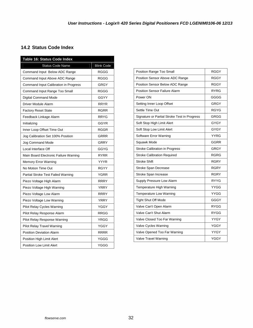
User Instructions - Logix® 420 Series Digital Positioners FCD LGENIM0106-06 12/13
flowserve.com 32
14.2 Status Code Index
Table 16: Status Code Index
Status Code Name Blink Code
Command Input Below ADC Range RGGG
Command Input Above ADC Range RGGG
Command Input Calibration in Progress GRGY
Command Input Range Too Small RGGG
Digital Command Mode GGYY
Driver Module Alarm RRYR
Factory Reset State RGRR
Feedback Linkage Alarm RRYG
Initializing GGYR
Inner Loop Offset Time Out RGGR
Jog Calibration Set 100% Position GRRR
Jog Command Mode GRRY
Local Interface Off GGYG
Main Board Electronic Failure Warning RYRR
Memory Error Warning YYYR
No Motion Time Out RGYY
Partial Stroke Test Failed Warning YGRR
Piezo Voltage High Alarm RRRY
Piezo Voltage High Warning YRRY
Piezo Voltage Low Alarm RRRY
Piezo Voltage Low Warning YRRY
Pilot Relay Cycles Warning YGGY
Pilot Relay Response Alarm RRGG
Pilot Relay Response Warning YRGG
Pilot Relay Travel Warning YGGY
Position Deviation Alarm RRRR
Position High Limit Alert YGGG
Position Low Limit Alert YGGG
Position Range Too Small RGGY
Position Sensor Above ADC Range RGGY
Position Sensor Below ADC Range RGGY
Position Sensor Failure Alarm RYRG
Power ON GGGG
Setting Inner Loop Offset GRGY
Settle Time Out RGYG
Signature or Partial Stroke Test in Progress GRGG
Soft Stop High Limit Alert GYGY
Soft Stop Low Limit Alert GYGY
Software Error Warning YYRG
Squawk Mode GGRR
Stroke Calibration in Progress GRGY
Stroke Calibration Required RGRG
Stroke Shift RGRY
Stroke Span Decrease RGRY
Stroke Span Increase RGRY
Supply Pressure Low Alarm RYYG
Temperature High Warning YYGG
Temperature Low Warning YYGG
Tight Shut Off Mode GGGY
Valve Can't Open Alarm RYGG
Valve Can't Shut Alarm RYGG
Valve Closed Too Far Warning YYGY
Valve Cycles Warning YGGY
Valve Opened Too Far Warning YYGY
Valve Travel Warning YGGY

User Instructions - Logix® 420 Series Digital Positioners FCD LGENIM0106-06 12/13
flowserve.com 33
14.3 Status Code Descriptions
GGGG POWER ON
Description: No issues. Possible Solutions: Not applicable.
GGGY TIGHT SHUT OFF MODE
Description: (Also called MPC.) The Final Command is beyond the user set limit for the tight shutoff feature and the positioner is applying full actuator pressure to close (or open) the valve. This is a normal condition for all valves when closed. The factory default setting triggers this at command signals below 1%. This indication may also occur on 3 way valves at both ends of travel if the upper Tight Shut Off value has been set. Possible Solutions: If tight shutoff is not desired reset the tight shutoff limits or adjust the command signal inside of the specified Tight Shut Off values.
GGYG LOCAL INTERFACE OFF
Description: Control and configuration features are locked at the positioner's local interface. This is to prevent unauthorized or accidental adjustments. The buttons can still be used to view information on the LCD. The status code is only present for a short time when the user attempts to make a change through the display menu. Possible Solutions: The DTM's Local Interface page is used to unlock the local interface, turn this feature on and off, and to set the PIN. For temporary access, a Personal Identification Number (PIN) can be entered from the positioner if an LCD is installed.
GGYY DIGITAL COMMAND MODE
Description: The input command is set by a digital HART command instead of the 4-20 mA signal. Possible Solutions: The input command source can be changed back to the 4-20 mA signal by using a handheld, the Dashboard page of the DTM, or performing a manual Command Reset. Perform the Command Reset by holding both the UP and DOWN buttons and briefly pressing the QUICK-CAL/ACCEPT button.
GGYR INITIALIZING
Description: The positioner has powered up and is displaying a blink sequence 3 times. Possible Solutions: Wait for 3 blink sequences to complete.
GGRR SQUAWK MODE
Description: A user has set the positioner to flash a special sequence so that it can be visually located. Possible Solutions: This mode is cancelled if one of the following occurs: 1) The QUICK-CAL/ACCEPT button is briefly pressed. 2) The Squawk mode is turned off remotely. 3) More than one hour has passed since the command was issued.
GYGY SOFT STOP HIGH LIMIT ALERT SOFT STOP LOW LIMIT ALERT
Description: The Final Command would move the valve beyond the user-set Soft Limit, but the internal software is holding the position at the limit. The function is similar to a mechanical limit stop except it is not active if the unit is un-powered. Possible Solutions: If more travel is needed, reset the Soft Limits. If not, adjust the Final Command signal back into the specified range.
GRGG SIGNATURE OR PARTIAL STROKE TEST IN PROGRESS
Description: The positioner is in Out Of Service (OOS) mode because a test or signature has been initiated. These include Step Test, Ramp Test, or Partial Stroke Test. Possible Solutions: Signatures and tests can be defined, initiated, and cancelled through the Off-Line Diagnostics pages of the DTM.

User Instructions - Logix® 420 Series Digital Positioners FCD LGENIM0106-06 12/13
flowserve.com 34
GRGY STROKE CALIBRATION IN PROGRESS SETTING INNER LOOP OFFSET COMMAND INPUT CALIBRATION IN PROGRESS
Description: A calibration sequence is in progress. The inner loop offset is an important step of the stroke calibration. Possible Solutions: The calibration can be canceled from the corresponding calibration page of the DTM, from the handheld, or by briefly pressing the BACK button.
GRRY JOG COMMAND MODE
Description: The positioner has been placed in a local override mode where the valve can only be stroked using the UP and DOWN buttons. The positioner will not respond to analog or digital input commands from HART. Possible Solutions: Control the valve using the UP and DOWN buttons. This mode may be cancelled by briefly pushing the QUICK-CAL/ACCEPT button.
GRRR JOG CALIBRATION SET 100% POSITION
Description: During a jog calibration, the unit is waiting for the user to manually adjust the valve position to the desired 100% open position. Possible Solutions: Use the Up and Down buttons on the positioner to adjust the valve to the desired fully open position. The QUICK-CAL/ACCEPT button to accept.
YGGG POSITION HIGH LIMIT ALERT POSITION LOW LIMIT ALERT
Description: The position has reached or is exceeding a user defined position limit. This is similar to a limit switch indicator. Possible Solutions: Set the limit to a higher (or lower) value if more travel is needed, or adjust the command signal back in the specified range.
YGGY PILOT RELAY CYCLES WARNING PILOT RELAY TRAVEL WARNING VALVE CYCLES WARNING VALVE TRAVEL WARNING
Description: The cycle or travel limit of the valve, actuator, bellows or pilot relay has been exceeded. Each cycle represents two reversals of the direction of valve movement. The cycle counting criterion and count limit (for the valve, actuator and bellows) are set by the user to track the usage of the valve assembly. Possible Solutions: Follow routine procedures for maintenance when the limit is reached. For example valve inspection may include checking the packing tightness, and checking linkages for wear, misalignment, and tightness. Bellows inspection may include checking bellows for cracking or leaking. Actuator inspection may include checking the actuator seals and lubrication. Relay inspection may include checking for high air consumption and signs of wear on the spool. After maintenance, reset the travel accumulator.
YGRR PARTIAL STROKE TEST FAILED WARNING
Description: Measured times or forces during the last partial stroke test did not pass the criteria set by the user. This may be an indication of corrosion build-up on the valve stem or in the actuator, low or restricted supply pressure, or a sticking positioner relay. Possible Solutions: This warning will clear upon completion of a successful partial stroke test.
YYGG TEMPERATURE HIGH WARNING TEMPERATURE LOW WARNING
Description: The temperature of the internal electronics has exceeded the manufacturer set limits of -40°C (-40°F) to 85°C (176°F). Low temperature may inhibit responsiveness and accuracy. High temperature may affect performance or limit the life of the positioner. Possible Solutions: Regulate the temperature of the positioner by shading or cooling supply gas. Heat the positioner if needed. If the temperature reading is in error, replace the main board.

User Instructions - Logix® 420 Series Digital Positioners FCD LGENIM0106-06 12/13
flowserve.com 35
YYGY VALVE CLOSED TOO FAR WARNING VALVE OPENED TOO FAR WARNING
Description: While the valve was in use, it closed or opened farther than it did at the last calibration by 0.5%. Possible Solutions: Check the feedback arm linkage and ensure the valve stem connection is tight. Recalibrate the stroke. If the process cannot be interrupted a service technician may be able to adjust the calibration.
YYYR MEMORY ERROR WARNING
Description: The microprocessor's memory has a problem. Possible Solutions: Error may clear with time. If error persists, cycle power and complete a QUICK-CAL. If the error still persists, perform a factory reset, reprogram or replace the main circuit board.
YYRG SOFTWARE ERROR WARNING
Description: There has been a watch dog time out, stack overflow warning, or CPU usage warning. Possible Solutions: If the problem persists, perform a factory reset. If it still persists, reprogram or replace the main board.
YRGG PILOT RELAY RESPONSE WARNING
Description: The pilot relay is sticking or slow to respond. This affects the responsiveness, increases the chance of limit cycling and excessive air consumption. The pilot relay is part of the inner loop and consists of the driver module assembly with piezo (I-P relay) which is coupled to the spool valve or poppet. The value of this indicator corresponds with inner loop lag. Delayed response can be caused by a partially clogged piezo or debris, oil, corrosion, or ice on the spool, or low supply pressure. Possible Solutions: Check response of the valve. If OK, adjust Pilot Relay Response limits. Check supply pressure. Check the spool or poppet for debris, oil, corrosion, ice on the spool. Clean or replace the spool or poppet assembly. Replace the piezo or driver module assembly. Maintain a clean, water-free air/gas supply.
YRRY PIEZO VOLTAGE HIGH WARNING PIEZO VOLTAGE LOW WARNING
Description: If the voltage to the piezo is to high, this could indicate an error with the relay or the main board. This may result from an extended period of inactivity, but in this case should not persist for more than 30 minutes when the valve is controlling. The positioner may still be functioning, but have reduced performance under some circumstances. If the voltage to the piezo is too low, the piezo may be damaged. This may prevent the proper failure position upon loss of signal/power. This condition may occur briefly on an air-to-close valve that is held for long periods of time in the closed position, or an air-to-open valve held in the open position. Possible Solutions: Ensure the supply pressure is not low. If alarm persists for more than 30 minutes, the Piezo assembly is damaged. Replace the pilot relay.
RGGG COMMAND INPUT BELOW ADC RANGE COMMAND INPUT ABOVE ADC RANGE COMMAND INPUT RANGE TOO SMALL
Description: During Command Loop Calibration, the signal was out of the Analog to Digital Converter (ADC) range, or difference between the signal at 0% and the signal at 100% was too small. The system is designed to accept a difference greater than 5 mA and between 10 and 4085 ADC. Possible Solutions: Recalibrate making sure to use valid command signal values.
RGGY POSITION RANGE TOO SMALL POSITION SENSOR ABOVE ADC RANGE POSITION SENSOR BELOW ADC RANGE
Description: During calibration, the range of motion of the position feedback arm was too small for optimum performance or the feedback sensor moved beyond its range of operation. Possible Solutions: Check for loose linkages. Adjust the positioner mounting. Adjust the feedback pin back into range. Adjust the feedback pin to a position closer to the follower arm pivot to create a larger angle of rotation and recalibrate. The minimum angle of rotation should be greater than 15 degrees. Briefly pressing the QUICK-CAL/ACCEPT button acknowledges a small range and the positioner will operate using the short stroke calibration if otherwise a good calibration.
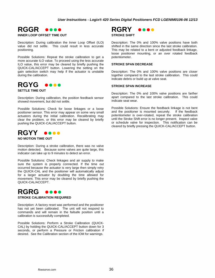
User Instructions - Logix® 420 Series Digital Positioners FCD LGENIM0106-06 12/13
flowserve.com 36
RGGR INNER LOOP OFFSET TIME OUT
Description: During calibration the Inner Loop Offset (ILO) value did not settle. This could result in less accurate positioning. Possible Solutions: Repeat the stroke calibration to get a more accurate ILO value. To proceed using the less accurate ILO value, this error may be cleared by briefly pushing the QUICK-CAL/ACCEPT button. Lowering the setting on the gain selection switch may help if the actuator is unstable during the calibration.
RGYG SETTLE TIME OUT
Description: During calibration, the position feedback sensor showed movement, but did not settle. Possible Solutions: Check for loose linkages or a loose positioner sensor. This error may appear on some very small actuators during the initial calibration. Recalibrating may clear the problem, or this error may be cleared by briefly pushing the QUICK-CAL/ACCEPT button.
RGYY NO MOTION TIME OUT
Description: During a stroke calibration, there was no valve motion detected. Because some valves are quite large, this indicator can take up to 9 minutes to detect an error. Possible Solutions: Check linkages and air supply to make sure the system is properly connected. If the time out occurred because the actuator is very large then simply retry the QUICK-CAL and the positioner will automatically adjust for a larger actuator by doubling the time allowed for movement. This error may be cleared by briefly pushing the QUICK-CAL/ACCEPT.
RGRG STROKE CALIBRATION REQUIRED
Description: A factory reset was performed and the positioner has not yet been calibrated. The unit will not respond to commands and will remain in the failsafe position until a calibration is successfully completed. Possible Solutions: Perform a Stroke Calibration (QUICK-CAL) by holding the QUICK-CAL/ACCEPT button down for 3 seconds, or perform a Pressure or Friction calibration if desired. See the Calibration section of the IOM for warnings.
RGRY STROKE SHIFT
Description: The 0% and 100% valve positions have both shifted in the same direction since the last stroke calibration. This may be related to a bent or adjusted feedback linkage, loose positioner mounting, or an over rotated feedback potentiometer. STROKE SPAN DECREASE
Description: The 0% and 100% valve positions are closer together compared to the last stroke calibration. This could indicate debris or build up at valve seat. STROKE SPAN INCREASE
Description: The 0% and 100% valve positions are farther apart compared to the last stroke calibration. This could indicate seat wear. Possible Solutions: Ensure the feedback linkage is not bent and the positioner is mounted securely. If the feedback potentiometer is over-rotated, repeat the stroke calibration until the Stroke Shift error is no longer present. Inspect valve or schedule valve for inspection. This notification can be cleared by briefly pressing the QUICK-CAL/ACCEPT button.
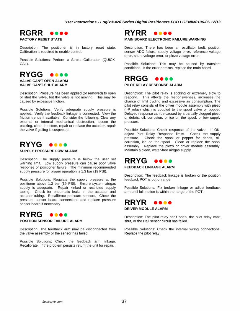
User Instructions - Logix® 420 Series Digital Positioners FCD LGENIM0106-06 12/13
flowserve.com 37
RGRR FACTORY RESET STATE
Description: The positioner is in factory reset state. Calibration is required to enable control. Possible Solutions: Perform a Stroke Calibration (QUICK-CAL).
RYGG VALVE CAN'T OPEN ALARM VALVE CAN'T SHUT ALARM
Description: Pressure has been applied (or removed) to open or shut the valve, but the valve is not moving. This may be caused by excessive friction. Possible Solutions: Verify adequate supply pressure is applied. Verify the feedback linkage is connected. View the friction trends if available. Consider the following: Clear any external or internal mechanical obstruction, loosen the packing, clean the stem, repair or replace the actuator, repair the valve if galling is suspected.
RYYG SUPPLY PRESSURE LOW ALARM
Description: The supply pressure is below the user set warning limit. Low supply pressure can cause poor valve response or positioner failure. The minimum recommended supply pressure for proper operation is 1.3 bar (19 PSI). Possible Solutions: Regulate the supply pressure at the positioner above 1.3 bar (19 PSI). Ensure system air/gas supply is adequate. Repair kinked or restricted supply tubing. Check for pneumatic leaks in the actuator and actuator tubing. Recalibrate pressure sensors. Check the pressure sensor board connections and replace pressure sensor board if necessary.
RYRG POSITION SENSOR FAILURE ALARM
Description: The feedback arm may be disconnected from the valve assembly or the sensor has failed. Possible Solutions: Check the feedback arm linkage. Recalibrate. If the problem persists return the unit for repair.
RYRR MAIN BOARD ELECTRONIC FAILURE WARNING
Description: There has been an oscillator fault, position sensor ADC failure, supply voltage error, reference voltage error, shunt voltage error, or piezo voltage error. Possible Solutions: This may be caused by transient conditions. If the error persists, replace the main board.
RRGG PILOT RELAY RESPONSE ALARM
Description: The pilot relay is sticking or extremely slow to respond. This affects the responsiveness, increases the chance of limit cycling and excessive air consumption. The pilot relay consists of the driver module assembly with piezo (I-P relay) which is coupled to the spool valve or poppet. Delayed response can be caused by a partially clogged piezo or debris, oil, corrosion, or ice on the spool, or low supply pressure. Possible Solutions: Check response of the valve. If OK, adjust Pilot Relay Response limits. Check the supply pressure. Check the spool or poppet for debris, oil, corrosion, ice on the spool. Clean or replace the spool assembly. Replace the piezo or driver module assembly. Maintain a clean, water-free air/gas supply.
RRYG FEEDBACK LINKAGE ALARM
Description: The feedback linkage is broken or the position feedback POT is out of range. Possible Solutions: Fix broken linkage or adjust feedback arm until full motion is within the range of the POT.
RRYR DRIVER MODULE ALARM
Description: The pilot relay can't open, the pilot relay can't shut, or the Hall sensor circuit has failed. Possible Solutions: Check the internal wiring connections. Replace the pilot relay.
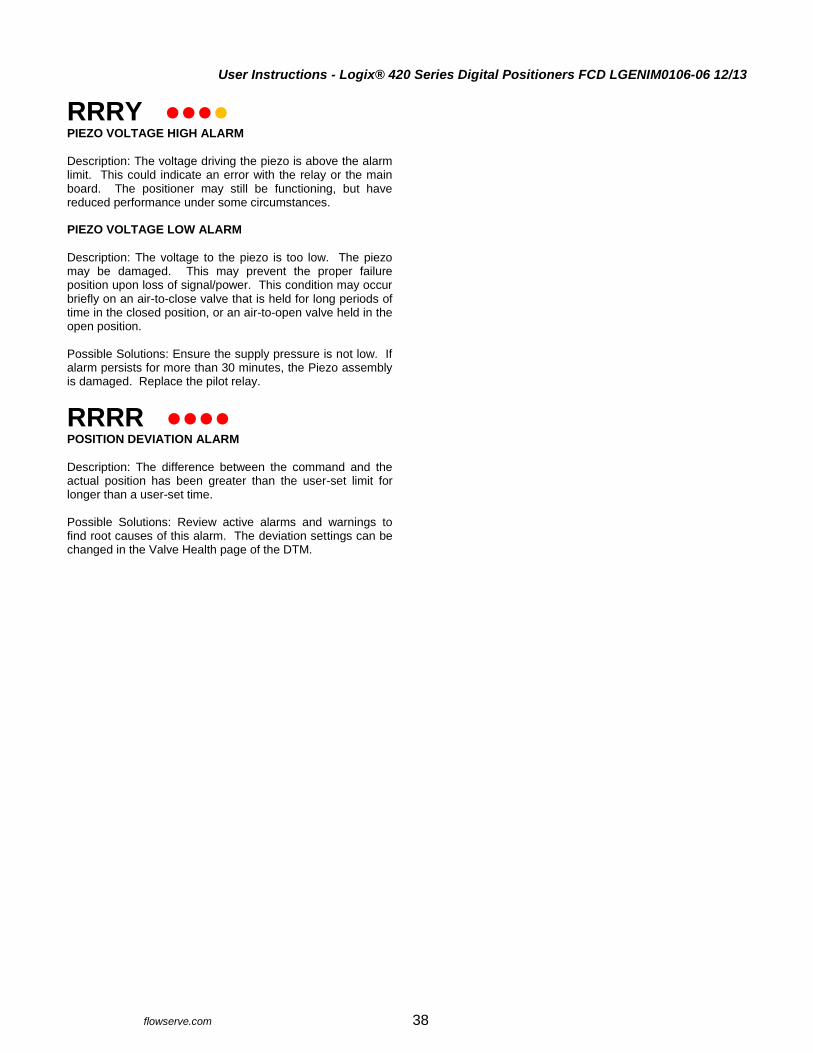
User Instructions - Logix® 420 Series Digital Positioners FCD LGENIM0106-06 12/13
flowserve.com 38
RRRY PIEZO VOLTAGE HIGH ALARM
Description: The voltage driving the piezo is above the alarm limit. This could indicate an error with the relay or the main board. The positioner may still be functioning, but have reduced performance under some circumstances. PIEZO VOLTAGE LOW ALARM
Description: The voltage to the piezo is too low. The piezo may be damaged. This may prevent the proper failure position upon loss of signal/power. This condition may occur briefly on an air-to-close valve that is held for long periods of time in the closed position, or an air-to-open valve held in the open position. Possible Solutions: Ensure the supply pressure is not low. If alarm persists for more than 30 minutes, the Piezo assembly is damaged. Replace the pilot relay.
RRRR POSITION DEVIATION ALARM
Description: The difference between the command and the actual position has been greater than the user-set limit for longer than a user-set time. Possible Solutions: Review active alarms and warnings to find root causes of this alarm. The deviation settings can be changed in the Valve Health page of the DTM.
User Instructions - Logix® 420 Series Digital Positioners FCD LGENIM0106-06 12/13
flowserve.com 39
14.4 Help From Flowserve
14.4.1 Phone Support
Over-the-phone troubleshooting is often available for positioner issues. Should your positioner be experiencing problems, or if you have questions that are not answered by this manual, feel free to call your local sales representative or a Quick Response Center (QRC). See the back cover of this manual for contact details.
14.4.2 Returning the 420 Positioner for Service
If troubleshooting is unable to solve the problem, the unit may be returned. Please follow the steps below.
1. Request a Return Goods Authorization (RGA) form. An RGA form will be e-mailed to you to accompany the unit being returned.
2. Remove all fittings, brackets, filters, feedback arms, etc. from the unit before packaging.
3. If the unit was operated with a gas other than clean air, please include the related MSDS with the return.
4. Complete the RGA form. Write any specific issues with the positioner you would like us to evaluate. Please include the customer name and contact information
5. When packaging, please secure the unit in a method that will insure it will reach our facility undamaged (the weight of positioners will often settle through packing peanuts and pop large air packets).
6. Please insert a copy of the completed RGA form inside the package and write the RGA number on the outside of the package. Send the unit to the address at the bottom of the form.
If the cause of the unit failure is found to be a manufacturing defect and the unit is within the warranty period (18 months from manufacture) it will be repaired free of charge. If no problem is found with the unit and the unit is still under warranty, a fee for the evaluation will be required. If the cause of the unit failure is not covered under the warranty a fee will be charged for the evaluation and a quote will be provided showing the cost of the repair. If the customer decides to purchase a new positioner, the evaluation fee will be waved.
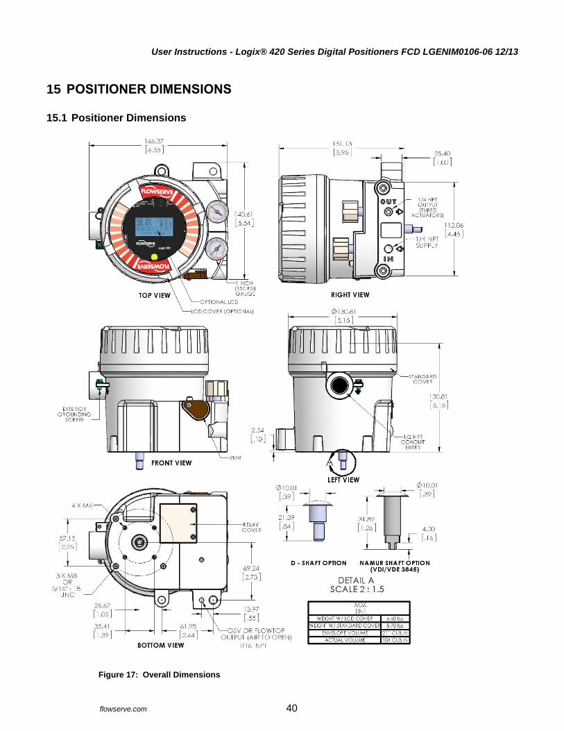
User Instructions - Logix® 420 Series Digital Positioners FCD LGENIM0106-06 12/13
flowserve.com 40
15 POSITIONER DIMENSIONS
15.1 Positioner Dimensions
Figure 17: Overall Dimensions
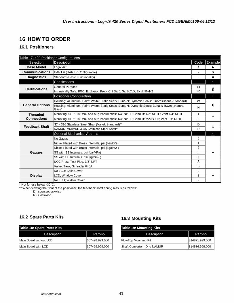
User Instructions - Logix® 420 Series Digital Positioners FCD LGENIM0106-06 12/13
flowserve.com 41
16 HOW TO ORDER
16.1 Positioners
Table 17: 420 Positioner Configurations
Selection Description Code Example
Base Model Logix 420 4
4
Communications HART 6 (HART 7 Configurable) 2
2
Diagnostics Standard (Basic Functionality) 0
0
Certifications
-
Certifications General Purpose 14 1
4
Intrinsically Safe, IP66, Explosion Proof Cl I Div 1 Gr. B,C,D, Ex d IIB+H2 40
Positioner Configuration
-
General Options
Housing: Aluminum; Paint: White; Static Seals: Buna-N; Dynamic Seals: Fluorosilicone (Standard) W
W Housing: Aluminum; Paint: White; Static Seals: Buna-N; Dynamic Seals: Buna-N (Sweet Natural
Gas)* N
Threaded Connections
Mounting: 5/16" 18 UNC and M6; Pneumatics: 1/4" NPTF; Conduit: 1/2" NPTF; Vent 1/4" NPTF 1 1
Mounting: 5/16" 18 UNC and M6; Pneumatics: 1/4" NPTF; Conduit: M20 x 1.5; Vent 1/4" NPTF 2
Feedback Shaft “D” - 316 Stainless Steel Shaft (Valtek Standard)** D D
NAMUR VDI/VDE 3845 Stainless Steel Shaft** R
Optional Mechanical Add-Ins
-
Gauges
No Gages 0
1
Nickel Plated with Brass Internals, psi (bar/kPa) 1
Nickel Plated with Brass Internals. psi (kg/cm2 ) 2
SS with SS Internals. psi (bar/kPa) 3
SS with SS Internals. psi (kg/cm2 ) 4
UCC Press Test Plug, 1/8" NPT A
Valve, Tank, Schrader 645A B
Display
No LCD; Solid Cover 0
1 LCD; Window Cover 1
No LCD; Widow Cover 2
* Not for use below -30°C. ** When viewing the front of the positioner, the feedback shaft spring bias is as follows:
D - counterclockwise R - clockwise
16.2 Spare Parts Kits
Table 18: Spare Parts Kits
Description Part-no.
Main Board without LCD 307428.999.000
Main Board with LCD 307429.999.000
16.3 Mounting Kits
Table 19: Mounting Kits
Description Part-no.
FlowTop Mounting Kit 314871.999.000
Shaft Converter - D to NAMUR 314586.999.000

User Instructions - Logix® 420 Series Digital Positioners FCD LGENIM0106-06 12/13
flowserve.com 42
INDEX
A
Air Action Switch · 15 Air Supply · 6 Auto Tune Switch · 16
C
Calibration · 16, 17, 21, 22, 23, 35, 36, 37 Characterization · 15, 16, 23 Command Source Reset · 18 Compliance Voltage · 12 Configuration Switch Settings · 15
D
DIP Switch Override · 20 Display Contrast · 20
E
Electrical Connections · 12 Event History · 21, 22
F
Factory Reset · 18, 26 FlowTop · 9 Friction · 16, 20, 36
H
Handheld Communicator · 27 HART · 4, 6, 20, 26, 27, 29 Hazardous Area Certifications · 7
I
Inner Loop · 5 Installation · 9
L
Language · 26 LCD Menu · 19 Limit Switch · 14 Local Control Of Valve Position · 18
Local User Interface · 15
M
Main Board · 30 Maintenance · 8, 29, 30 MaxFlo Rotary Valves · 10 Minimum Close Time · 23 Minimum Open Time · 23 Mounting · 9
O
Outer Loop · 5
P
Partial Stroke Test · 21, 22, 33 Performance · 6 Positioner Dimensions · 40 Pressure Control · 16, 20, 24
Q
Quick Calibration Switch · 16 Quick-Cal · 15
R
Repair · 30
S
Safety · 3 Shutoff · 25 Signal at Closed Switch · 15 Soft Limits · 25 Spare Parts · 3, 41 Specifications · 6 Status Code · 16, 32, 33 Status Icons · 20 Status Messages · 20 Stroke Calibration · 15, 16 Stroke Time · 23
T
Temperature · 6, 20, 21, 22, 25 Troubleshooting · 12, 31

User Instructions - Logix® 420 Series Digital Positioners FCD LGENIM0106-06 12/13
flowserve.com 43
Tubing · 11 Tuning · 18, 23
V
Valtek GS · 9
Valve Cycles · 22 Valve Stability Switch · 16 Valve Travel · 22 ValveSight DTM · 6, 27 Vented Design · 11 Version Numbers · 19, 26

User Instructions - Logix® 420 Series Digital Positioners FCD LGENIM0106-06 12/13
flowserve.com 44
Flowserve Headquarters 5215 N. O'Connor Blvd. Suite 2300 Irving, Tx. 75039 Phone: +1 972 443 6500
Flowserve Corporation Flow Control 1350 N. Mt. Springs Parkway Springville, UT 84663 USA Phone: +1 801 489 8611 Fax: +1 801 489 3719
Flowserve S.A.S. 12, avenue du Quebec B.P. 645 91965 Courtaboeuf Cedex France Phone: +33 (0) 1 60 92 32 51 Fax: +33 (0) 1 60 92 32 99
Flowserve Pte Ltd. 12 Tuas Avenue 20 Singapore 638824 Singapore Phone:+ 65 6868 4600 Fax: +65 6862 4940
Flowserve Australia Pty Ltd. 14 Dalmore Drive Scoresby, Victoria 3179 Australia Phone: +61 7 32686866 Fax: +61 7 32685466
Flowserve Ltda . Rua Tocantins, 128 São Caetano do Sul, SP 09580-130 Brazil Phone: +55 11 2169 6300 Fax: +55 11 2169 6313
Flowserve Control Valves gmbH Control Valves - Villach Operation Kasernengasse 6 9500 Villach Austria Phone: +43 (0)4242 41181 0 Fax: +43 (0)4242 41181 50
Flowserve (China) 585, Hanwei Plaza 7 Guanghau Road Beijing, China 100004 Phone: +86 10 6561 1900
Flowserve India Controls Pvt. Ltd Plot # 4, 1A, E.P.I.P, Whitefield Bangalore Kamataka India 560 066 Phone: +91 80 284 10 289 Fax: +91 80 284 10 286
Flowserve Essen GmbH Schederhofstr. 71 45145 Essen Germany Phone: +49 (0)201 8919 5 Fax: +49 (0)201 8919 600
Kämmer Valves inc. 1300 Parkway View Drive Pittsburgh, Pa 15205 USA Tel.: +1 412 787 8803 Fax: +1 412 787 1944
NAF Ab Gelbgjutaregatan 2 SE-581 87 Linköping Sweden Phone: +46 (0)13 31 61 00 Fax: +46 (0)13 13 60 54
Bulletin FCD LGENIM0106-06 12/13 Control per SPP-250
To find your local Flowserve representative please use the Sales Support Locator System found at www.flowserve.com Or call Europe +43 (0) 4242 41181 999 North America +1 801 489-2300 Asia + (65) 6879 8900 [email protected]
Flowserve Corporation has established industry leadership in the design and manufacture of its products. When properly selected, this Flowserve product is designed to perform its intended function safely during its useful life. However, the purchaser or user of Flowserve products should be aware that Flowserve products might be used in numerous applications under a wide variety of industrial service conditions. Although Flowserve can (and often does) provide general guidelines, it cannot provide specific data and warnings for all possible applications. The purchaser/user must therefore assume the ultimate responsibility for the proper sizing and selection, installation, operation, and maintenance of Flowserve products. The purchaser/user should read and understand the Installation Operation Maintenance (IOM) instructions included with the product, and train its employees and contractors in the safe use of Flowserve products in connection with the specific application. While the information and specifications contained in this literature are believed to be accurate, they are supplied for informative purposes only and should not be considered certified or as a guarantee of satisfactory results by reliance thereon. Nothing contained herein is to be construed as a warranty or guarantee, express or implied, regarding any matter with respect to this product. Because Flowserve is continually improving and upgrading its product design, the specifications, dimensions and information contained herein are subject to change without notice. Should any question arise concerning these provisions, the purchaser/user should contact Flowserve Corporation at any one of its worldwide operations or offices. © 2012 Flowserve Corporation, Irving, Texas, USA. Flowserve is a registered trademark of Flowserve Corporation. For more information about Flowserve Corporation, contact www.flowserve.com or call USA 1-800-225-6989.
Download Logix 420 Manual
(Certification information in manual may not be applicable. Certifications on positioner label are valid.)